Counter Name Mkt Grade Counter Name Mkt Grade Counter Name ...

Journal of Research and Practice in Information Technology, Vol. 42, No. 3, August 2010 171
FBDVerifier: Interactive and Visual Analysis of Counter-example in Formal Verification of Function Block DiagramEunkyoung Jee1
Div. of Computer Science, Korea Advanced Institute of Science and TechnologyRepublic of Korea Email: [email protected]
Seungjae Jeon Samsung Electronics Co. Ltd., Republic of Korea Email: [email protected]
Sungdeok Cha Dept. of Computer Science and Engineering, Korea UniversityRepublic of Korea Email: [email protected]
Kwangyong Koh Dept. of Nuclear and Quantum Engineering, Korea Advanced Institute of Science and Technology, Republic of Korea Email: [email protected]
Junbeom Yoo Div. of Computer Science and Engineering, Konkuk UniversityRepublic of Korea Email: [email protected]
Geeyong Park I&C and Human Factors Center, Korea Atomic Energy Research InstituteRepublic of Korea Email: [email protected]
Poonghyun Seong Dept. of Nuclear and Quantum Engineering, Korea Advanced Institute of Science and Technology, Republic of Korea Email: [email protected]
Manuscript received: 8 October 2008Communicating Editor: Chiou-Peng Lam
Copyright© 2010, Australian Computer Society Inc. General permission to republish, but not for profit, all or part of thismaterial is granted, provided that the JRPIT copyright notice is given and that reference is made to the publication, to itsdate of issue, and to the fact that reprinting privileges were granted by permission of the Australian Computer Society Inc.
1 Current address: Department of Computer and Information Science, University of Pennsylvania, 3330 Walnut Street,Philadelphia PA 19104.
Model checking is often applied to verify safety-critical software implemented in programmablelogic controller (PLC) language such as a function block diagram (FBD). Counter-examplesgenerated by a model checker are often too lengthy and complex to analyze. This paper describesthe FBDVerifier which allows domain experts to perform automated model checking and intuitivevisual analysis of counter-examples without having to know technical details on temporal logic or
JRPIT 42.3.QXP_Layout 1 22/09/10 12:04 PM Page 171

FBDVerifier: Interactive and Visual Analysis of Counter-example in Formal Verification of Function Block Diagram
Journal of Research and Practice in Information Technology, Vol. 42, No. 3, August 2010172
the model checker. Once the FBD program is automatically translated into a semanticallyequivalent Verilog model and model checking is performed using SMV, users can enter variousexpressions to investigate why verification of certain properties failed. When applied to FBDprograms implementing a shutdown system for a nuclear power plant, domain engineers were ableto perform effective FBD verification and detect logical errors in the FBD design.
Keywords: Function Block Diagram, Formal Verification, Counter-example Visualization,Verilog Translation, Programmable Logic Controller, Model Checking
ACM Classification: D.2.4 (Software/Program Verification – Model Checking), F.3.1(Specifying and Verifying and Reasoning about Programs – Mechanical verification)
1. INTRODUCTIONFormal methods, especially model checking, are widely accepted as a useful technique whenverifying behaviour of safety-critical embedded software. Such a trend is also true in the nuclearindustry where Programmable Logic Controller (PLC) based software is increasingly replacingtraditional analog systems (NRC, 1997). As an example, Korea Nuclear Instrumentation & ControlSystem R&D Center (KNICS) has developed a reactor protection system (RPS) in Function BlockDiagram (FBD) which is one of the widely used PLC programming languages defined in the IECstandard. Model checking has been applied to FBD design as a part of its safety assuranceprogram.
When performing model checking, despite the advantage that the process is fully automated, oneencounters the following challenges: (1) state explosion, and (2) counter-example analysis oftenrequires tracking values of several hundred variables over several hundred or thousand steps (SeeFigure 6 for an example). Although efficient counter-example analysis has not received as muchresearch attention as the state explosion problem, it is one of the most significant and practicalobstacles that domain engineers face on real-world projects. In addition, temporal logic theory andnotation often causes engineers to avoid using model checking techniques altogether.
For example, our target system, KNICS RPS, has a natural language specification ranging from190 pages to 365 pages for three major subsystems. When FBD programs are translated intoSynchronous Verilog (IEEE, 2003) model and model checking is performed using SMV, manualanalysis of a counter-example often involved tracking of more than 100 independent integervariables, and it often took at least a half-day of engineer time to analyze each case. Consideringthat model checking of three subsystems generated over 100 counter-examples, it is apparent thatmanual analysis is simply impractical.
To cope with these problems, we developed a tool, the FBDVerifier, which allows an interactiveand visual analysis of counter-examples generated by a model checker. The current prototypesupports the automated conversion of FBDs into semantically equivalent Verilog models andanalysis of SMV counter-examples. The FBDVerifier visualizes a counter-example generated bySMV in a timing graph manner which is familiar to nuclear engineers. Users can insert and monitorhow values of various expressions change over time to identify causes of unsatisfied properties. TheFBDVerifier allows domain experts to perform automated model checking and intuitive visualanalysis of counter-examples without in-depth technical knowledge on model checking theory or theSMV model checker.
We verified the Advanced Power Reactor’s (APR-1400) RPS. With the FBDVerifier toolsupport, counter-example analysis became a more efficient and less complex task than before.Furthermore, nuclear engineers were able to complete the entire analysis without the help of formalmethods experts and find logical errors hidden in the preliminary design.
JRPIT 42.3.QXP_Layout 1 22/09/10 12:04 PM Page 172

FBDVerifier: Interactive and Visual Analysis of Counter-example in Formal Verification of Function Block Diagram
Journal of Research and Practice in Information Technology, Vol. 42, No. 3, August 2010 173
The remainder of the paper is organized as follows: Section 2 explains FBD, Verilog and SMVbriefly. Section 3 describes the formal definition of FBD, translation rules from FBD into Verilogand the FBDVerifier. Section 4 presents a case study for a real industrial system. Section 5 presentsrelated works, and we conclude this paper at Section 6.
2. BACKGROUNDPLC is an industrial computer system applied to a wide range of control systems. The maincharacteristic of a PLC program is its cyclic execution (Mader, 2000). The program reads inputs,computes new internal states, and updates outputs at each iteration of the permanent loop.
FBD is one of the standard PLC programming languages (IEC61131, 1993). FBD is widely usedbecause of its graphical notations and usefulness in implementing applications where a high degreeof data flow exists among components. FBD defines system behaviour in terms of flow of signalsamong function blocks. A collection of function blocks is wired together in the manner of a circuitdiagram.
Figure 1 shows an example FBD which is a small part of the FBD program for the RPS. Outputvariables are calculated by sequential combinations of the function or function block operations.The output variable TRIP_LOGIC is set to true when the processing value PV_OUT exceeds theset-point TSP continuously for more than the specified duration, K_DELAY. The TRIP_LOGICoutput takes part in the shutdown logic of a nuclear reactor.
Figure 1: An example FBD: a part of FIX_RISING module of a reactor protection system
JRPIT 42.3.QXP_Layout 1 22/09/10 12:04 PM Page 173

FBDVerifier: Interactive and Visual Analysis of Counter-example in Formal Verification of Function Block Diagram
Journal of Research and Practice in Information Technology, Vol. 42, No. 3, August 2010174
An FBD program consists of functions and function blocks. Functions (e.g., GE, AND and SELblocks in Figure 1) do not have internal states while function blocks (e.g., TON in Figure 1) storevalues in internal and output variables (Lewis, 1998).
Verilog (IEEE, 2003) is one of the most popular Hardware Description Languages (HDL) usedby integrated circuit (IC) designers. In order to verify FBD programs, we chose Verilog as averification language because the semantics of FBD is similar to that of Verilog. Another reason isthat Verilog models can be used for equivalence checking as well as model checking. In this paper,we focus only on model checking of FBD programs and visual analysis of counter-examples. (SeeYoo (2005) for a discussion on equivalence checking technique.)
Model checking is a technique to prove whether a system satisfies certain properties or not. Wechose Cadence SMV (SMV, 2008) as a model checker to verify Verilog models generated from FBDprograms. Other Verilog model checkers can also be used. Cadence SMV can verify a modelprogrammed by Synchronous Verilog (SV) (Chou, 1997) as well as SMV input language. SV is asubset of Verilog language.
3. FBD VERIFICTION THROUGH VERILOG TRANSLATIONIn order to verify FBD, we must first translate the FBD program into a semantically equivalentVerilog model. We define the function block and the function block diagram formally based onideas discussed in Yoo (2005). Next, we discuss what it means for a FBD to be well-formed. Thethird subsection shows the translation steps and rules using the example. The last subsectiondescribes the FBDVerifier’s features for automatic translation and visual counter-example analysis.
3.1 Formal Definition of FBDAn FBD program is a network of function blocks. Each function block is considered as an instanceof a function block type.
Definition 1. (Function Block Type) Function block type is defined as a tuple <Type_name, IP,OP, BD>, where• Type_name: a name of function block type • IP: a set of input ports, {IP1, ... , IPM}• OP: a set of output ports, {OP1, ... , OPN}• BD: behaviour description, as functions for each OP,
BDOPn: (IP1, ... , IPM) OPn, 1 ≤ n ≤ N
Input port (IP) and output port (OP) are official terms used in the IEC standard (IEC61131,1993). In Figure 1, and1 and and2 are instance names of function block type AND, and sel1-sel4are instance names of function block type SEL. For a better understanding, we added instance namesmanually in the middle of each function block because pSET (PSET, 2008), the PLC editor, whichwe used, does not represent instance names of function blocks explicitly. We write sel1.G to indicatethe port named G of the sel1 function instance. The behavioural description of the add1 functioninstance is written as add1.BDOUT(add1.IN1, add1.IN2) = add1.IN1 + add1.IN2.
Definition 2. (Function Block Diagram) FBD is defined as a tuple <FBs, V, T>, where• FBs: a set of function block instances• V: a set of input and output variables of FBD, V = VI ∪ VO
– VI: a set of input variables into FBD– VO: a set of output variables from FBD
JRPIT 42.3.QXP_Layout 1 22/09/10 12:04 PM Page 174

FBDVerifier: Interactive and Visual Analysis of Counter-example in Formal Verification of Function Block Diagram
Journal of Research and Practice in Information Technology, Vol. 42, No. 3, August 2010 175
• T: a set of transitions between FBs and FBs, and FBs and V,T = (VI × FB.IP) ∪ (FB.OP × FB.IP) ∪ (FB.OP × VO)
VI is a set of input variables and each ν ∈ VI has a constant value or the value of the outputvariable having the same name. VO is a set of output variables computed at each scan cycle. Thetransitions set T includes connections between function blocks and also connections betweenfunction blocks and variables. Figure 2 shows a formal definition of the example FBD in Figure 1.
Definition 3. (Evaluation Function) Each port and variable is evaluated by evaluation function f: • For input variable vi ∈ VI, f (vi) = vi
• For output variable vo ∈ VO, f (vo) = f (po) where po is an output port and (po, vo) ∈ T• For input port pi ∈ fb.IP, fb ∈ FBs, f (pi) = f (vi) where vi is an input variable and (vi , pi) ∈ T• For output port po ∈ fb.OP, fb ∈ FBs, f (po) = fb.BDpo(p1, ..., pM) where fb.IP = { p1, ..., pM}
Output variables of FBD are evaluated with the connected function blocks and the inputs of thefunction block. For example, TSP_1 in Figure 1 is evaluated as follows:
f (TSP_1) = f ( sel2.OUT )= sel2.BDOUT ( f ( sel2.G ), f ( sel2.IN1 ), f ( sel2.IN2 ) )= f ( sel2.G ) ? f ( sel2.IN2 ) : f ( sel2.IN1 )= f ( ton1.Q ) ? sub1.BDOUT ( f ( sub1.IN1 ), f ( sub1.IN2 ) ) : TSP= ton1.BDQ ( f ( ton1.IN ), f ( ton1.PT ) ) ? ( f ( sub1.IN1 ) - f ( sub1.IN2 ) ) : TSP= ton1.BDQ ( f ( and1.OUT ), K_DELAY ) ? (TSP - HYS) : TSP = ton1.BDQ ( ( ( PV_OUT >= TSP) && ! TRIP_LOGIC), K_DELAY) ? (TSP - HYS) : TSP
3.2 Well-formed FBDWe assume that the FBDs to be verified are well-formed. Informal description for the well-formedFBD is stated in IEC 61131-3, but it does not necessarily mean that FBD design is logically correct.A well-formed FBD must satisfy the following criteria:
Output variables are not overwritten• Every output variable must have a unique name so that its value can be assigned only once in
each cycle.
Each function block is evaluated in specific and predetermined order• Output variables are evaluated in predetermined order chosen based on data and control
dependency. For the ordered set of output variables VO = {vo1, ..., voN}, computation starts fromvo1 and ends at voN within a cycle.
< FBs, V, T>FBs = { ge1, and1, ton1, sel1, ..., add1, sel4 }V_I = { PV_OUT, TSP, TRIP_LOGIC, K_DELAY, HYS, TRIP_LOGIC_1, TSP_1}V_O = {IN_TIME, TRIP_LOGIC_1, TSP_1, TRIP_LOGIC, TSP}T = { (PV_OUT, ge1.IN1), (TSP, ge1.IN2), (ge1.OUT, and1.IN1), (¬TRIP_LOGIC, and1.IN2),
(and1.OUT, ton1.IN), (K_DELAY, ton1.PT), ... , (and2.OUT, sel4.G), (TSP_1, sel4.IN1),(add1.OUT, sel4.IN2), (sel4.OUT, TSP) }
Figure 2: A formal definition of the FBD program in Figure 1
JRPIT 42.3.QXP_Layout 1 22/09/10 12:04 PM Page 175

FBDVerifier: Interactive and Visual Analysis of Counter-example in Formal Verification of Function Block Diagram
Journal of Research and Practice in Information Technology, Vol. 42, No. 3, August 2010176
All input ports and output ports are connected to a variable or suitable port• Every output port is connected to a variable or an input port.
∀po: po ∈ fb.OP, fb ∈ FBs ⇒ ( ∃v: v ∈ V ∧ ( po, v ) ∈ T ) or ( ∃pi: pi ∈ FB.IP ∧ ( po, pi ) ∈ T )• Every input port is connected by a variable or an output port.
∀pi: pi ∈ fb.IP, fb ∈ FBs ⇒ ( ∃v: v ∈ V ∧ ( v, pi ) ∈ T ) or ( ∃po: po ∈ FB.OP ∧ ( po, pi ) ∈ T )
FBD is type safe• ∀(x, y) ∈ T, x and y should have the same data type. FBD data types are defined in the standard.
Basically, if an FBD program is not well-formed, it cannot be translated into a semantic-preserving Verilog model automatically. The FBDVerifier provides some assistant functions tosupport FBD programs which are not well-formed. If an FBD development tool allows overwritingof output variables, the FBDVerifier automatically changes output variables to unique names. If anexecution order is not explicitly specified, the FBDVerifier calculates the execution order of eachblock automatically according to the general rules included in the IEC standard. Most PLC editorscheck unconnected wiring and unmatched types before compiling.
3.3 Translation RulesTranslation rules of a well-defined FBD into a Verilog model follow the template in Figure 3.
//Rule 1. Module declaration module main (clk, [input_ports], [output_ports]);
// Rule 2. Variable type and size decision for each variable v ∈ Vinput | reg | wire | output [size(v) : 0] v;
// Rule 3. Initialization of each reg variable vreginitial begin vreg = [initial_value_of_ vreg]; end
// Rule 4. Output assignment for each wire and output variable v ∈ VO ∈ VWassign v = f(v);
// Rule 5. Declaration of other module instances MODULE1 module1_instance_name(clk, [input_ports], [output_ports]);
// Rule 6. Stored value assignment for each reg variable vreg: always @ (posedge clk) begin vreg = [stored_value]; end
// Rule 7. Insertion of properties always begin {if [condition]} assert [label]: [assertion]; end endmodule
module MODULE1 (clk, [input_ports], [output_ports]); … endmodule
Figure 3: Verilog model generation template
JRPIT 42.3.QXP_Layout 1 22/09/10 12:05 PM Page 176

FBDVerifier: Interactive and Visual Analysis of Counter-example in Formal Verification of Function Block Diagram
Journal of Research and Practice in Information Technology, Vol. 42, No. 3, August 2010 177
Rule 1. Module declarationA module is the principal design entry in Verilog. The first line of a module declaration specifies themodule name and list of input/output ports.
Rule 2. Variable type and size decisionAll variables are declared with their type, bit size, and name in Rule 2. Each variable in the FBD ismapped to one of the Verilog variable types; input, reg, wire and output. Variable type detection canbe automated by analyzing the usage of variables in the target FBD.
Non-Boolean values are represented as bit vectors in Synchronous Verilog accepted by SMV.Determining the number of bits (e.g., range) to be allocated for a variable is a crucial choice to bemade based on domain knowledge. If it is too large, model checking may fail due to the stateexplosion problem while attempting to exhaustively search all reachable states. If it is too small,incomplete state analysis will be performed and incorrect results returned. Such an error isespecially critical if the model checker finds the properties to be true. While the bit size of the inputand reg variables should be given by a user, the bit size of the wire and output variables can becomputed with connected variables and function blocks automatically.
Rule 3. Initialization of reg variablesThe reg variables are initialized in Rule 3. Usually initial values of reg variables are specified in theFBD program. If not, they are determined by a user or assigned default values.
Rule 4. Output assignment for each wire and output variableIn Rule 4, the target FBD represented by a set of connected function blocks is translated intoassignment statements from top to bottom in accordance with the execution order of the FBD.While a function which does not have internal state is mapped into a Verilog operator, a functionblock which stores the internal state is mapped into a Verilog module.
The assignment expression for an output variable v has the same form as f (v) in definition 3.We defined and implemented an evaluation function for each output variable of all functions andfunction blocks of IEC 61131-3 except numerical functions, because numerical functions such asSIN and LOG cannot be handled properly by an SMV model checker.
Rule 5. Declaration of other module instancesA user-defined function or function block can be defined in PLC programming. When an FBDprogram has a hierarchical structure with user-defined blocks, corresponding a Verilog model, italso consists of a hierarchy of modules. In Rule 5, instances of other modules are declared. Othermodules are declared outside the main module.
Rule 6. Stored value assignment for reg variablesThe stored values are assigned to the reg variables in Rule 5. @(posedge clk) means the positiveedge of the clock signal, i.e., the beginnings of each cycle. As the updated value of a reg variablebecomes available at the next time unit, the new value is read at the next cycle (McMillan, 2001).
Rule 7. Insertion of propertiesThe template always begin – end is generated automatically and properties are embedded by a userafter automatic generation of a Verilog model.
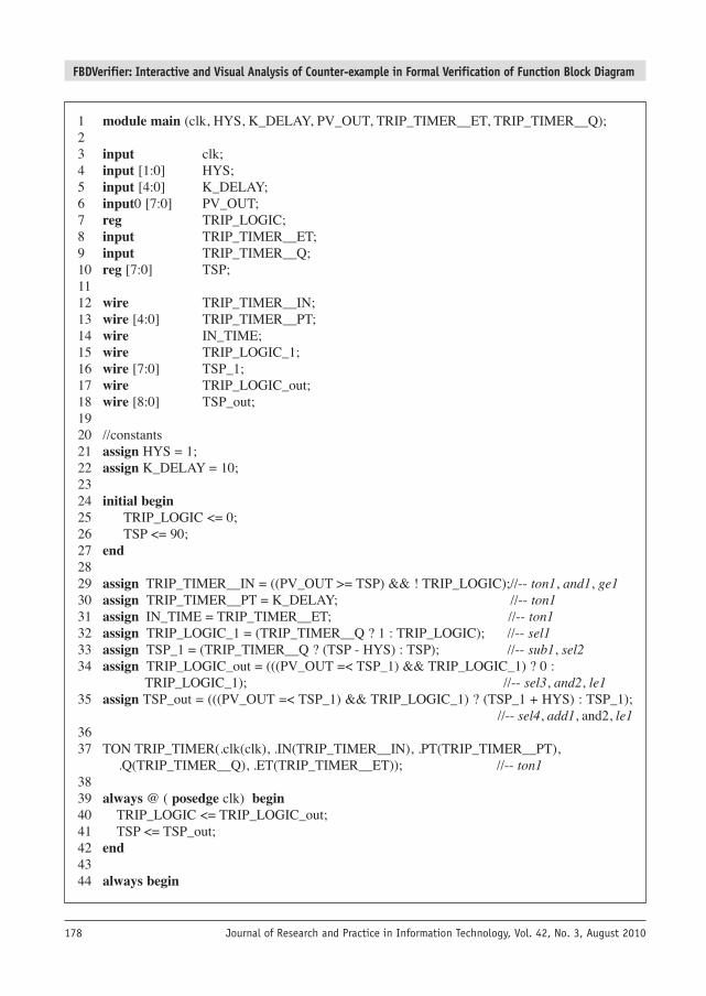
Verilog model generation exampleFigure 4 shows a Verilog model generated from the FIX_RISING FBD module in Figure 1. Totranslate the FIX_RISING program into a Verilog model, we detect the variable type first. As HYS,
JRPIT 42.3.QXP_Layout 1 22/09/10 12:05 PM Page 177
FBDVerifier: Interactive and Visual Analysis of Counter-example in Formal Verification of Function Block Diagram
Journal of Research and Practice in Information Technology, Vol. 42, No. 3, August 2010178
1 module main (clk, HYS, K_DELAY, PV_OUT, TRIP_TIMER__ET, TRIP_TIMER__Q);2 3 input clk;4 input [1:0] HYS;5 input [4:0] K_DELAY;6 input0 [7:0] PV_OUT;7 reg TRIP_LOGIC;8 input TRIP_TIMER__ET;9 input TRIP_TIMER__Q;10 reg [7:0] TSP;11 12 wire TRIP_TIMER__IN;13 wire [4:0] TRIP_TIMER__PT;14 wire IN_TIME;15 wire TRIP_LOGIC_1;16 wire [7:0] TSP_1;17 wire TRIP_LOGIC_out;18 wire [8:0] TSP_out;19 20 //constants21 assign HYS = 1;22 assign K_DELAY = 10;23 24 initial begin25 TRIP_LOGIC <= 0;26 TSP <= 90;27 end28 29 assign TRIP_TIMER__IN = ((PV_OUT >= TSP) && ! TRIP_LOGIC);//-- ton1, and1, ge130 assign TRIP_TIMER__PT = K_DELAY; //-- ton131 assign IN_TIME = TRIP_TIMER__ET; //-- ton132 assign TRIP_LOGIC_1 = (TRIP_TIMER__Q ? 1 : TRIP_LOGIC); //-- sel133 assign TSP_1 = (TRIP_TIMER__Q ? (TSP - HYS) : TSP); //-- sub1, sel234 assign TRIP_LOGIC_out = (((PV_OUT =< TSP_1) && TRIP_LOGIC_1) ? 0 :
TRIP_LOGIC_1); //-- sel3, and2, le135 assign TSP_out = (((PV_OUT =< TSP_1) && TRIP_LOGIC_1) ? (TSP_1 + HYS) : TSP_1);
//-- sel4, add1, and2, le136 37 TON TRIP_TIMER(.clk(clk), .IN(TRIP_TIMER__IN), .PT(TRIP_TIMER__PT),
.Q(TRIP_TIMER__Q), .ET(TRIP_TIMER__ET)); //-- ton138 39 always @ ( posedge clk) begin40 TRIP_LOGIC <= TRIP_LOGIC_out;41 TSP <= TSP_out;42 end43 44 always begin
JRPIT 42.3.QXP_Layout 1 22/09/10 12:05 PM Page 178

FBDVerifier: Interactive and Visual Analysis of Counter-example in Formal Verification of Function Block Diagram
Journal of Research and Practice in Information Technology, Vol. 42, No. 3, August 2010 179
PV_OUT and K_DELAY appear only in the input variable set VI, they have input type.TRIP_LOGIC, and TSP are reg type variables whose values are stored and used at the next cycle.TSP_1 and TRIP_LOGIC_1 appear in both the input and output variable sets. Their values areassigned in wires and become inputs to evaluate other variables, but they are not stored for the next cycle, i.e., wire type. TRIP_TIMER__ET, TRIP_TIMER__Q, TRIP_TIMER__IN andTRIP_TIMER__PT are variables related to the TON timer function block with the instance nameTRIP_TIMER. For the input and output ports of a function block, wire and input type variables aredeclared. They are used to connect the main module with a separate function block module, asshown in line 37.
System specification states that HYS and K_DELAY have constant values and TRIP_LOGICand TSP have specific initial values; they are coded in lines 21 through 27. In lines 29 through 35,each wire and output variable is assigned by a specific expression according to Rule 4. Aftergeneration of a Verilog model from the FBD program, properties are embedded using if and assertstructures in lines 44 through 48.
3.4 FBDVerifier Tool3.4.1 Automatic TranslationWe developed a tool, the FBDVerifier, to automate the FBD verification framework. Figure 5 is ascreen dump of the FBDVerifier. It takes the LDA file format as input and converts it into a Verilogmodel automatically. The LDA format is used in pSET (PSET, 2008) which is the PLC softwaredevelopment environment used in the study. In the translation process, the FBDVerifier allows auser to choose the bit size and initial values of the variables. After the Verilog translation iscompleted, a user inserts properties to be verified into the Verilog model and executes the CadenceSMV with one click in the FBDVerifier. The left-side window of the FBDVerifier shows the FBDin textual format and the right-side window shows the translated Verilog model.
Figure 4: A Verilog model for the FIX_RISING FBD program in Figure 1
45 if (PV_OUT = TSP) && IN_TIME = K_DELAY) assert P1: TRIP_LOGIC_out == 1;46 if (TRIP_LOGIC && PV_OUT = TSP) assert P2: TRIP_LOGIC_out == 1;47 end48 endmodule49 50 module TON (clk, IN, PT, Q, ET);51 input clk, IN;52 input [4:0] PT;53 output Q;54 output [4:0] ET;55 reg [4:0] t;56 initial t = 0;57 assign ET = t;58 assign Q = IN && (ET = PT);59 always @ ( posedge clk)60 t <= IN ? ((t < PT) ? t+1 : PT) : 0;61 endmodule
JRPIT 42.3.QXP_Layout 1 22/09/10 12:05 PM Page 179

FBDVerifier: Interactive and Visual Analysis of Counter-example in Formal Verification of Function Block Diagram
Journal of Research and Practice in Information Technology, Vol. 42, No. 3, August 2010180
3.4.2 Counter-example VisualizationWhen a target FBD has a lot of variables and the properties do not hold, counter-examples are oftenlengthy and complex. It is difficult to analyze counter-examples only with the table-style trace viewprovided by the Cadence SMV. Figure 6 shows a counter-example for a sub module of the BP whichcontains about 1,000 rows of variables and more than 20 columns of steps.
To enhance the readability of a counter-example, we implemented a graphical display of acounter-example in the FBDVerifier. The FBDVerifier displays a counter-example generated bySMV in the form of a timing graph as shown in Figure 7. Variables are highlighted in differentcolours and shapes for effective visualization.
In order to aid effective counter-example analysis, the FBDVerifier enables users to insert user-defined expressions and monitor changes to their values. For example, in the FIX_RISINGprogram, if domain engineers wish to know if and when the processing value (PV_OUT) meets orexceeds the trip set-point (TSP), an expression, PV_OUT >= TSP, can be typed in the counter-
Figure 5: A screen dump of the FBDVerifier
JRPIT 42.3.QXP_Layout 1 22/09/10 12:05 PM Page 180

FBDVerifier: Interactive and Visual Analysis of Counter-example in Formal Verification of Function Block Diagram
Journal of Research and Practice in Information Technology, Vol. 42, No. 3, August 2010 181
example view window. A corresponding timing graph is displayed at the bottom of the rightwindow. It is important to note that expressions accepted by the FBDVerifier are at the problemdomain (e.g., variables) rather than bit vectors processed by a model checker.
The FBDVerifier also provides several features to simplify counter-example analysis while notcompromising accuracy. For example, variables with the same values through all steps are groupedin a timing graph. Users can choose which aspects of the timing graph are to be displayed (e.g.,outputs only). Likewise, display of each graph can be turned on or off anytime. Domain experts findtiming graphs intuitive and easy to analyze so that little training is necessary when using the tool.They also do not have to possess in-depth technical knowledge on temporal logic or modelcheckers.
4. CASE STUDY4.1 Target SystemWe have applied the proposed technique to the APR-1400 Reactor Protection System (RPS)(RPSSDS, 2006) which consists of a Bistable Processor (BP), a Coincidence Processor (CP), an
Figure 6: A complex counter-example of BP in Cadence SMV
JRPIT 42.3.QXP_Layout 1 22/09/10 12:05 PM Page 181

FBDVerifier: Interactive and Visual Analysis of Counter-example in Formal Verification of Function Block Diagram
Journal of Research and Practice in Information Technology, Vol. 42, No. 3, August 2010182
Automatic Test and an Interface Processor (ATIP) and a Cabinet Operation Module (COM)subsystem. BP, CP and ATIP subsystems are safety-critical systems while COM is safety-related.The regulatory organization requires safety-critical systems be formally verified as a part of itssafety assurance program.
Table 1 shows relevant statistics on the RPS. The software design specification document for theRPS has approximately 700 pages and the FBD program for the RPS is composed of approximately20,000 function blocks and 9,000 variables. The Verilog model generated from the FBD for the RPSconsists of more than 14,000 lines.
Figure 7: Counter-example visualization of the FBDVerifier
RPS #pages of #function #lines ofsubsystems natural lang. spec. blocks
#variablesVerilog model
BP 190 1,335 1,038 7,862
CP 163 1,623 820 3,085
ATIP 365 18,359 7,024 3,401
Table 1: RPS system information
JRPIT 42.3.QXP_Layout 1 22/09/10 12:05 PM Page 182

FBDVerifier: Interactive and Visual Analysis of Counter-example in Formal Verification of Function Block Diagram
Journal of Research and Practice in Information Technology, Vol. 42, No. 3, August 2010 183
4.2 Properties and Verification ResultsWe used the Cadence SMV model checker to verify a Verilog model translated from an FBDprogram. Properties are inserted as a form of “assert label: cond;” between always begin and endin the Verilog model.
Properties to be verified were derived jointly by nuclear engineers and formal methods experts.In the RPS system, trip, i.e. reactor shutdown signal, is the most critical output. The trip output mustbe generated only when the trip condition is met. Otherwise, a safety hazard may occur. It is alsoessential that the reactor is not erroneously shut down to avoid substantial financial losses. Loss ofpublic confidence in nuclear safety is another risk which is too great to quantify. Table 2 showsexamples of properties which a module in BP must satisfy.
We verified the BP mostly on safety properties and found 10 distinct errors among 47 errors intotal. Similar results were obtained when CP and ATIP systems, more complex than BP, wereanalyzed using FBDVerifier. Entire analysis took three man-months which is considered a short-time compared to similar analysis conducted previously.
Table 3 summarizes the verification results. We categorized detected errors into five categoriesaccording to their root causes. Errors in the Incorrect logic category are the most serious ones.Errors belonging to the Ambiguous logic category are potentially serious if certain environmentalconditions are met. The Incorrect FBD category represents the cases where the FBD specification
No. Properties (in natural language)
1 When the trip condition is satisfied, trip should occur.
2 When the trip release condition is satisfied, trip should release.
3 Trip set-point value should be in valid range.
4 When trip and pretrip did not occur, trip set-point and pretrip set-point should keep the specified difference.
5 When the processing value is in invalid range, range error should occur.
6 When the heartbeat of the other system is unsound, heartbeat error should occur.
Table 2: Examples of verification properties for the BP
Target subsystems BP CP ATIP
#properties 216 83 126
Detected Incorrect logic 14 6 23errors
Omission 0 2 0
Ambiguous logic 4 0 3
Incorrect FBD 13 5 9
Incorrect SDS 16 0 11
Total #errors 47 13 46
Distinct #errors 10 3 14
Table 3: Verification result for RPS
JRPIT 42.3.QXP_Layout 1 22/09/10 12:05 PM Page 183
FBDVerifier: Interactive and Visual Analysis of Counter-example in Formal Verification of Function Block Diagram
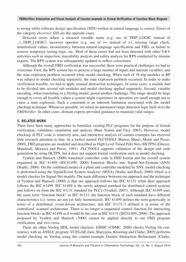
Journal of Research and Practice in Information Technology, Vol. 42, No. 3, August 2010184
is wrong while software design specification (SDS) written in natural language is correct. Errors ofthe category Incorrect SDS are the opposite cases.
Detected errors where a misused variable name (e.g. use of TRIP_LOGIC instead of_1_TRIP_LOGIC), incorrect operator (e.g. use of >= instead of >), missing range check,uninitialized values, inconsistency between natural language specification and FBD, or failure toremove temporary testing logic, etc. Most of these errors had not been detected with other V&Vactivities such as inspection, traceability analysis and safety analysis for RPS conducted by domainexperts. The RPS system was subsequently updated to reflect corrections.
Although the overall FBD verification was successful, there were practical challenges we had toovercome. First, the RPS system has to process a large number of inputs and internal variables, andthe state explosion problem occurred while model checking. When each of 18 trip modules in BPwas subject to model checking separately, the state explosion problem occurred. In order to makeverification feasible, we had to apply manual abstraction techniques. In some cases, a module hadto be divided into several sub modules and model checking applied separately. Second, variableencoding, when translating to a Verilog model, posed another challenge. The range should be largeenough to cover all feasible values a system might experience in operation yet small enough not tocause a state explosion. Such a constraint is an inherent limitation associated with the modelchecking technique. Whenever possible, we relied on automated range detection logic built-in to theFBDVerifier. In other cases, domain experts provided guidance to maintain valid ranges.
5. RELATED WORKThere have been many approaches to formalize existing PLC programs for the purpose of formalverification, validation, simulation and analysis (Bani Younis and Frey, 2003). However, modelchecking of PLC code is relatively new, and interactive analysis of counter-examples has receivedlittle research attention to date. In a toolset named PLCTOOLS (Baresi, Mauri, Monti and Pezze,2000), FBD programs are modeled and described as High Level Timed Petri Nets (HLTPN) (Ghezzi,Mandrioli, Morasca and Pezze, 1991). PLCTOOLS supports validation of the design and codegeneration by using HLTPN, but it does not support formal verification such as model checking.
Vyatkin and Hanisch (2000) translated controller code in FBD format and the overall systemorganized in IEC 61499 (IEC61499, 2000) Function Blocks into Signal-Net-Systems (SNS)(Starke, 2000). On the combined model of a plant and controller modeled by SNS, model-checkingis performed using the Signal/Event System Analyzer (SESA) (Starke and Roch, 2000) which is amodel-checker for Signal-Net models. The main difference between our approach and the techniqueof Vyatkin and Hanisch (2000) is that our approach follows the IEC 61131 while their approachfollows the IEC 61499. IEC 61499 is the newly adopted standard for distributed control systemsand follows on from the IEC 61131 standard for PLCs (Vyatkin, 2007). Although IEC 61499 usesthe same term “function block” as IEC 61131, the function block of each standard have differentcharacteristics (i.e. terms are not yet fully harmonized). IEC 61499 defines the term generically interms of a distributed, event-driven architecture, and IEC 61131-3 defined it in terms of thecentralized, scanned architecture. There is no longer a sequential control function for interactingfunction blocks in IEC 61499 as it would be the case in IEC 61131 (IEC61499, 2000). The approachproposed by Vyatkin and Hanisch (2000) cannot be applied directly to our FBD programverification, and vice versa.
There are other Verilog HDL model checkers. CBMC (CBMC, 2008) checks Verilog for con -sistency with an ANSI-C program. VCEGAR (Jain, Sharygina, Kroening and Clarke, 2005) performsmodel checking on Verilog using the counter-example Guided Abstraction Refinement (Clarke,
JRPIT 42.3.QXP_Layout 1 22/09/10 12:05 PM Page 184
FBDVerifier: Interactive and Visual Analysis of Counter-example in Formal Verification of Function Block Diagram
Journal of Research and Practice in Information Technology, Vol. 42, No. 3, August 2010 185
Grumberg, Jha, Lu and Veith, 2003) framework. Verilog models generated from FBD programs inour framework can also be verified using other Verilog model checkers instead of the Cadence SMV.In order to support visualization of counter-examples from other model checkers, the currentprototype of the FBDVerifier needs to be extended.
Several approaches to visualize SMV counter-examples were proposed (Smv2vcd, 2008;Goldsby, Cheng, Konrad and Kamdoum, 2006; Simmons, Pecheur and Srinivasan, 2000). Thesmv2vcd (Smv2vcd, 2008) converts SMV counter-examples into industrial standard format,Variable Change Dump (VCD). Generated VCD files can be viewed and analyzed by a wide varietyof tools. To the best of our knowledge, VCD viewers do not support interactive analysis ormonitoring expression function which are supported by the FBDVerifier. Theseus (Goldsby et al,2006) visualizes counter-examples from SPIN (Holzmann, 2003) or SMV model checkers in termsof UML. They verify formal specifications generated from UML models and counter-examples arevisualized on the state and sequence diagrams. Simmons et al (2000) proposed the idea that the statetransitions in the SMV counter-example are translated into a log file format that the visualizationtool associated with the original high-level language expects. Both Theseus and the possible tool ofSimmons et al (2000) cannot be utilized in our work because our target language is FBD. None ofthe aforementioned counter-example visualization tools offer interactive variable slicing ormonitoring expression function.
6. CONCLUSIONWe proposed a formal verification technique for FBD which is a commonly used PLC programminglanguage. We suggested the translation rules from an FBD program into a Verilog model anddeveloped the FBDVerifier to automate the FBD verification framework and support visual andinteractive counter-example analysis. We performed model checking for the Verilog modelsgenerated from industrial FBD programs and successfully found errors that other V&V techniquesfailed to detect.
Contributions of this paper follow: First, FBD program could be thoroughly verified by modelchecking using the FBDVerifier. Second, the FBDVerifier aids efficient analysis of counter-examplegenerated by the Cadence SMV by providing functions such as counter-example visualization,declaration of monitoring expressions, and slicing. The FBDVerifier considerably reduces time andefforts necessary for analyzing why properties did not hold. Third, we conducted an industrial casestudy in which we verified the FBD programs of the KNICS APR-1400 RPS with the proposedmethod. Large and complex FBD programs were verified effectively in a short time, and founderrors contributed to the improvement of the system safety. Domain experts were able to use theFBDVerifier without having to know much about model checking or temporal logic.
The current FBDVerifier receives only LDA file format used in pSET. We are extending theFBDVerifier to support other FBD storing formats such as XML. We have a plan to extend theFBDVerifier to support other PLC programming languages besides FBD. More systematic abstractionmethod instead of manual abstraction for the FBD verification is also a promising research topic.
ACKNOWLEDGEMENTThis research was partially supported by the National IT Industry Promotion Agency (NIPA) underthe program of Software Engineering Technologies Development and also partially supported bythe MKE (The Ministry of Knowledge Economy), Korea, under the ITRC (Information TechnologyResearch Center) support program supervised by NIPA. Project names are NIPA-2010-(C1090-1031-0001), NIPA-2010-(C1090-0903-0004) and NIPA-2010-(C1090-1031-0003).
JRPIT 42.3.QXP_Layout 1 22/09/10 12:05 PM Page 185
FBDVerifier: Interactive and Visual Analysis of Counter-example in Formal Verification of Function Block Diagram
Journal of Research and Practice in Information Technology, Vol. 42, No. 3, August 2010186
REFERENCESBANI YOUNIS, M. and FREY, G. (2003): Formalization of existing PLC programs: A survey. In Proc. of Computing
Engineering in Systems Applications (CESA), Lille, France. BARESI, L., MAURI, M., MONTI, A. and PEZZE, M. (2000): PLCTools: Design, formal validation, and code generation for
programmable controllers. In Proc. of the IEEE Int Conf on System, Man, and Cybernetics, Nashville, USA, 2437–2442. CBMC (2008): Bounded model checking for ANSI-C. http://www.cs.cmu.edu/~modelcheck/cbmc. Accessed 30-Sep-2008.CHOU, C.T. (1997): Synchronous Verilog: A proposal. Fujitsu Laboratories of America. CLARKE, E., GRUMBERG, O., JHA, S., LU, Y. and VEITH, H. (2003): Counter-example-guided abstraction refinement
for symbolic model checking. Journal of the ACM, 50(5): 752–794. GHEZZI, C., MANDRIOLI, D., MORASCA, S. and PEZZE, M. (1991): A unified high-level petri net model for time-critical
system. IEEE Transactions on Software Engineering, 17(2):160–172. GOLDSBY, H., CHENG, B.H.C., KONRAD, S. and KAMDOUM, S. (2006): A visualization framework for the modeling
and formal analysis of high assurance systems. Model Driven Engineering Languages and Systems (MoDELS), LNCS4199, 707–721.
HOLZMANN, G. (2003): The spin model checker. Addison-Wesley. IEC61131 (2003): IEC61131-3, International standard for programmable controllers: Programming languages Part 3.
International Electrotechnical Commission.IEC61499 (2000): IEC61499, Function blocks for industrial process measurement and control systems. International
Electrotechnical Commission, Tech. Comm. 65, Working group 6, Committee draft.IEEE (2003): IEEE Standard 1364-2001, Standard hardware description language based on the Verilog hardware description
language. IEEE.JAIN, H., SHARYGINA, N., KROENING, D. and CLARKE, E. (2005): Word level predicate abstraction and refinement for
verifying RTL Verilog. In Proc. 42nd Design Automation Conference (DAC), Anaheim, USA. LEWIS, R. (1998): Programming industrial control systems using IEC 1131-3 Revised Edition (IEE Control Engineering
Series). The Institute of Electrical Engineers. MADER, A. (2000): A classification of PLC models and applications. In Proc. 5th Int Workshop on Discrete Event Systems
(WODES), Ghent, Belgium.McMILLAN, K.L. (2001): Getting started with SMV. Cadence Berkeley Labs. NRC (1997): Digital instrumentation and control systems in nuclear power plants: Safety and reliability issues. U.S. NRC.
National Academy Press.PSET (2008): pSET, POSCON Software Engineering Tool. http://rnd.poscon.co.kr. Accessed 30-Sep-2008.RPSSDS (2006): KNICS-RPS-SDS231 Rev.01, Software design specification for reactor protection system. Doosan Heavy
Industries and Construction Co., Ltd.SIMMONS, R., PECHEUR, C. and SRINIVASAN, G. (2000): Towards automatic verification of autonomous systems. In
IEEE/RSJ International conference on Intelligent Robots & Systems, 1410–1415.SMV (2008): Cadence SMV. http://www.cadence.com. Accessed 30-Sep-2008.SMV2VCD (2008): smv2vcd. http://www.cs.cmu.edu/~modelcheck/smv2vcd.html. Accessed 30-Sep-2008.STARKE, P. (2000): Symmetries of signal-net systems. In Proc. of the Workshop on Concurrency, Specification and
Programming, Berlin, 285–297. STARKE, P. and ROCH, S. (2000): Analysing signal-net systems. Report, Humboldt University Berlin, Institut fur Informatik. VYATKIN, V. and HANISCH, H.M. (2000): Modeling of IEC 61499 function blocks – a clue to their verification. In Proc.
of the XI Workshop on Supervising and Diagnostics of Machining Systems, Karpacz, Poland, 59–68.VYATKIN, V. (2007): IEC 61499 Function blocks for embedded and distributed control systems design. ISA.YOO, J. (2005): Synthesis of function block diagrams from NuSCR formal specification. Ph.D thesis. Korea Advanced Institute
of Science and Technology (KAIST), Korea.
BIOGRAPHICAL NOTESEunkyoung Jee was a PhD candidate at the Korea Advanced Institute of Scienceand Technology (KAIST) when working on this research. She received her BS,MS, and PhD degrees in computer science from KAIST. Her research interestincludes safety-critical software, software testing, and formal method. She iscurrently a postdoctoral researcher at the University of Pennsylvania.
Eunkyoung Jee
JRPIT 42.3.QXP_Layout 1 22/09/10 12:05 PM Page 186

FBDVerifier: Interactive and Visual Analysis of Counter-example in Formal Verification of Function Block Diagram
Journal of Research and Practice in Information Technology, Vol. 42, No. 3, August 2010 187
Seungjae Jeon received his BS and MS degrees in computer science at KAIST.He implemented the initial version of the FBD Verifier which containedVerilog translation logic and visualization feature for analyzing counter-example. He is currently employed as a software quality assurance member inSamsung Electronics. His research interest is program static analysis forembedded domain.
Sungdeok (Steve) Cha, corresponding author, is a professor in the College ofInformation and Communiction at Korea University in Seoul, Korea. He isalso the director of the Center for Enginering and Education of DependableSoftware (CEEDS) at Korea University. Prior to joining Korea University, hewas a professor in the Computer Science Division at KAIST from 1994 to2008. His research interests include software engineering, software safety, andcomputer security. Cha received his BS, MS and PhD degrees in Informationand Computer Science from UC Irvine.
Kwangyong Koh received the BS degree in Nuclear Engineering fromHanyang University in 2004 and the MS degree in Nuclear and QuantumEngineer ing from Korea Advanced Institute of Science and Technology(KAIST) in 2006. Since 2006, he has been a PhD student in Nuclear andQuantum Engineering at KAIST. His research interests include software safetyanalysis, model checking and formal specification and verification.
Junbeom Yoo is an assistant professor in Konkuk University’s Department ofComputer Science and Engineering. His research interests include require -ments engineering, safety analysis and formal methods. Yoo has a PhD incomputer science from the Korea Advanced Institute of Science andTechnology in 2005.
Geeyong Park received the MS degree (1992) and PhD degree (1996) innuclear engineering from Korea Advanced Institute of Science and Technology(KAIST), Daejeon, Korea. From 1996, he was involved to the Instrumentation& Control and Human Factors division of Korea Atomic Energy ResearchInstitute (KAERI). His research interests cover software safety analysis,reliability and security analyses of nuclear digital systems, softwareverification and validation, control and monitoring of nuclear systems.
Seungjae Jeon
Sungdeok Cha
Kwangyong Koh
Junbeom Yoo
Geeyong Park
JRPIT 42.3.QXP_Layout 1 22/09/10 12:05 PM Page 187

FBDVerifier: Interactive and Visual Analysis of Counter-example in Formal Verification of Function Block Diagram
Journal of Research and Practice in Information Technology, Vol. 42, No. 3, August 2010188
Poonghyun Seong is currently a professor in Nuclear Engineering at KAIST,Korea. He received his BS degree from Seoul National University in 1977, MSand PhD degrees from MIT, USA in 1984 and 1987, respectively. He workedfor the Agency for Defense Development as a research scientist from 1977 to1982. He also worked for AT&T Bell laboratories from 1987 to 1991. Hejoined KAIST as a professor in 1991. His research interest includes NuclearPower Plant I&C and Human System Interactions.
Poonghyun Seong
JRPIT 42.3.QXP_Layout 1 22/09/10 12:05 PM Page 188