Velocity measurements in liquid metal flows using the Ultrasonic
6
Velocity measurements in liquid metal flows using the Ultrasonic Doppler Method: examples and perspectives Sven Eckert * and G. Gerbeth Forschungszentrum Dresden-Rossendorf (FZD), MHD Department, P.O: Box 510119, 01314 Dresden, Germany (*Corresponding author, e-mail: s.eckert@fzd. de). The Ultrasound Doppler Method (UDM) can be considered as an attractive technique to obtain velocity data from opaque flows. In this presentation various applications of UDM in liquid metal flows will be shown to demonstrate the capabilities and current restrictions of this technique. For instance, we consider flow fields arising from an electromagnetic stirring, discuss the application of UDM for measurements in liquid metal two-phase flows and present velocity measurements obtained during the solidification of metallic alloys. Besides the determination of velocity profiles in a solidifying melt the UDM data allow for an assessment of the current position of the solidification front, too. Specific problems arising in the context of UDM measurements in liquid metal experiments will be discussed. To extend the application range towards higher temperatures and abrasive liquids a new integrated ultrasonic sensor with an acoustic wave guide has been designed. For instance, successful measurements have been reported for liquid aluminium at temperatures of about 750°C. Keywords: Liquid metal, Ultrasound Doppler method, High temperature sensor, electromagnetic stirring, solidification 1 INTRODUCTION Considerable expenditure is permanently focussed on the optimisation of methods and facilities for material processing technologies like melting, refining or casting of metals and alloys. The main goals are an improvement of the final product quality, an enhancement of the process efficiency and an economical consumption of resources and energy. In processes involving electrically conducting liquids, the application of an external magnetic field offers efficient opportunities for a contact-less flow control and fluid handling. Further developments require a better knowledge about the details of the flow structure, the heat and mass transfer properties of the flow especially during phase transitions like melting or solidification. Numerical simulations could provide a better understanding of such processes, but experimental data of the velocity field are indispensable for validation of the CFD codes. The instrumentation of liquid metal flows for obtaining flow quantities like velocity, pressure, void fraction, properties of a dispersed phase etc. has to be considered as very difficult issue. No matter what diagnostic method is chosen, some serious restrictions always exist with respect to the particular sensors, for instance, the material properties of the liquid metal, the amount of impurities, the velocity range, the accuracy of the method, or the presence of electromagnetic fields. Considerable problems arise from the opaqueness of the liquid, the high temperatures or the corrosiveness of the fluid. As a consequence, there is a very constrained choice of commercially available techniques to measure the velocity structure in metallic melts at high temperatures. During the last 20 years the ultrasound Doppler technique (UDM) became a powerful tool for flow velocity measurements in fluid engineering [1]. The feasibility of velocity measurements in liquid metals using UDM was demonstrated for the first time by Takeda [2], who determined velocity profiles in a T-tube filled with mercury. Further successful applications have been published in different kind of liquid metal flows, see for instance [3–7]. The number of publications concerned with liquid metal flow measurements by means of UDM is still manageable, but, continuously increasing during the last years (for a recent review see [8] and references therein). The purpose of this paper is to provide a brief review with respect to the capabilities and restrictions of the considered measuring technique in liquid metal applications. The UDM technique is capable to deliver valuable insight in miscellaneous flow situations, occurring for instance during electromagnetic stirring [9, 10], during solidification of metallic alloys [11], inside a mercury target for a spallation source [12] or in liquid metal two-phase flows [13]. 2 SPECIFIC PROBLEMS ARISING FROM THE APPLICATION OF UDM IN LIQUID METALS 2.1 General Issues In this chapter we intend to discuss specific problems which have particularly to be taken into account if the Ultrasound Doppler Method is applied for velocity measurements in liquid metal flows. The main issues concern in particular: Top 6th International Symposium on Ultrasonic Doppler Methods for Fluid Mechanics and Fluid Engineering 1
Transcript of Velocity measurements in liquid metal flows using the Ultrasonic

Velocity measurements in liquid metal flows using the Ultrasonic Doppler Method: examples and perspectives
Sven Eckert* and G. Gerbeth Forschungszentrum Dresden-Rossendorf (FZD), MHD Department, P.O: Box 510119, 01314 Dresden, Germany (*Corresponding author, e-mail: [email protected]).
The Ultrasound Doppler Method (UDM) can be considered as an attractive technique to obtain velocity data from opaque flows. In this presentation various applications of UDM in liquid metal flows will be shown to demonstrate the capabilities and current restrictions of this technique. For instance, we consider flow fields arising from an electromagnetic stirring, discuss the application of UDM for measurements in liquid metal two-phase flows and present velocity measurements obtained during the solidification of metallic alloys. Besides the determination of velocity profiles in a solidifying melt the UDM data allow for an assessment of the current position of the solidification front, too. Specific problems arising in the context of UDM measurements in liquid metal experiments will be discussed. To extend the application range towards higher temperatures and abrasive liquids a new integrated ultrasonic sensor with an acoustic wave guide has been designed. For instance, successful measurements have been reported for liquid aluminium at temperatures of about 750°C.
Keywords: Liquid metal, Ultrasound Doppler method, High temperature sensor, electromagnetic stirring, solidification
1 INTRODUCTION Considerable expenditure is permanently focussed on the optimisation of methods and facilities for material processing technologies like melting, refining or casting of metals and alloys. The main goals are an improvement of the final product quality, an enhancement of the process efficiency and an economical consumption of resources and energy. In processes involving electrically conducting liquids, the application of an external magnetic field offers efficient opportunities for a contact-less flow control and fluid handling. Further developments require a better knowledge about the details of the flow structure, the heat and mass transfer properties of the flow especially during phase transitions like melting or solidification. Numerical simulations could provide a better understanding of such processes, but experimental data of the velocity field are indispensable for validation of the CFD codes. The instrumentation of liquid metal flows for obtaining flow quantities like velocity, pressure, void fraction, properties of a dispersed phase etc. has to be considered as very difficult issue. No matter what diagnostic method is chosen, some serious restrictions always exist with respect to the particular sensors, for instance, the material properties of the liquid metal, the amount of impurities, the velocity range, the accuracy of the method, or the presence of electromagnetic fields. Considerable problems arise from the opaqueness of the liquid, the high temperatures or the corrosiveness of the fluid. As a consequence, there is a very constrained choice of commercially
available techniques to measure the velocity structure in metallic melts at high temperatures. During the last 20 years the ultrasound Doppler technique (UDM) became a powerful tool for flow velocity measurements in fluid engineering [1]. The feasibility of velocity measurements in liquid metals using UDM was demonstrated for the first time by Takeda [2], who determined velocity profiles in a T-tube filled with mercury. Further successful applications have been published in different kind of liquid metal flows, see for instance [3–7]. The number of publications concerned with liquid metal flow measurements by means of UDM is still manageable, but, continuously increasing during the last years (for a recent review see [8] and references therein). The purpose of this paper is to provide a brief review with respect to the capabilities and restrictions of the considered measuring technique in liquid metal applications. The UDM technique is capable to deliver valuable insight in miscellaneous flow situations, occurring for instance during electromagnetic stirring [9, 10], during solidification of metallic alloys [11], inside a mercury target for a spallation source [12] or in liquid metal two-phase flows [13].
2 SPECIFIC PROBLEMS ARISING FROM THE APPLICATION OF UDM IN LIQUID METALS 2.1 General Issues In this chapter we intend to discuss specific problems which have particularly to be taken into account if the Ultrasound Doppler Method is applied for velocity measurements in liquid metal flows. The main issues concern in particular:
Top 6th International Symposium on Ultrasonic Doppler Methods for Fluid Mechanics and Fluid Engineering
1

• Thermal restrictions of the ultrasonic transducer in hot metallic melts
• Acoustic coupling between different materials along the ultrasonic path transducer – fluid
• Resonance effects arising from transmission through container walls
• Allocation of suitable tracer particles in the fluid An approach to solve the temperature problem will be presented in the next subsection. Here, we consider especially the wetting, the beam transmission and the reflecting particles. A good wetting contact between the liquid metal and the active acoustic surface is a prerequisite to guarantee the reception of Doppler signals. The large surface tension of the liquid metals and the almost inevitable existence of oxide layers complicate the wettability significantly. Non-wetted surfaces can cause a sudden change of the acoustic impedance, which obstructs the beam transmission into the fluid to be measured. In many experiments, the liquid metal flow to be measured is enclosed by stainless steel walls. Ultrasonic measurements through such walls require a careful removal of oxide layers at the steel surface by a suitable thermal [14] or chemical treatment [4], respectively. In case of an insufficient acoustic coupling at the inner wall multiple reflections are generated inside the wall material provoking a saturation of the transducer by the wall echoes. The generation of Doppler signals inside the liquid requires the existence of reflecting particles. We are not aware of any detailed, quantitative studies in liquid metals focussing on the dependence of the signal properties on quantities like the concentration, the morphology (e.g. size and shape) and the acoustic properties of the suspended scatter particles. Difficulties arise if these particles should be added in a well-controlled way to the metallic melts. Such particles have to be homogeneously distributed over the entire fluid volume and their liquid density must approximately be matched in order to prevent a slip between the flow field and the particle motion. Moreover, a wetting of the particles by the liquid metal is necessary: on the one hand, to enable the infiltration into the bulk liquid, on the other hand, to avoid agglomeration effects. Furthermore, for keeping the overall contamination by impurities at an acceptable level an efficient method must be available to separate the particles from the fluid after finishing the measurements. Having all these problems in mind, it is obvious to try to work solely with natural impurities such as oxides or microbubbles which are normally present in metallic melts having a technical purity standard. Noble liquid metals, such as mercury, contain an insufficient amount of natural tracers, whereas in customary alloys such as GaInSn, PbSn or PbBi a distinct and expeditious oxidation can only be
prevented with substantial effort. Here, the situation could arise that the UDM measurements might even be complicated by too many tracers inside the measuring volume [3]. A possible solution for the problem of the insufficient amount of seeding particles in mercury was proposed by Takeda and Kikura [15]. They injected nitrogen bubbles through a capillary tube into the liquid metal. Whereas the larger bubbles are expected to separate quickly from the liquid by the buoyancy force tiny bubbles can persist for a while as suitable reflectors. 2.2 Sensor for high temperature applications The crucial problem of the high temperatures of the metallic melts impedes the application of standard ultrasonic transducers. The use of the conventional transducer made of PZT based materials confines the range of application of ultrasonic techniques to maximum temperatures of about 150°C (long term load) and 200°C (short term load), respectively. If the measurements have to be performed with a direct contact between the ultrasonic probe and the metallic melt, one has to take care for a sufficient wetting between the probe and the liquid metal in order to guarantee a good acoustic contact, but on the other hand, the sensor has to be saved against a chemical reactions or dissolution in the melt. For this reason a new concept of an ultrasonic transducer with integrated acoustic wave guide has been proposed [5] in order to achieve a thermal as well as a chemical decoupling between the active transducer and the fluid. Stainless steel was proven to work as a dedicated wave-guide material in a temperature range until about 750°C. From the acoustic point of view there are also some ceramic materials as suitable candidates, however, it is difficult to achieve a sufficient wetting between a liquid metal and a solid ceramic surface at moderate temperatures. The integrated ultrasonic probe consisting of the piezoelectric element and the acoustic wave-guide is shown in Fig. 1. The working frequency of the transducer can be chosen between 1 and 4 MHz. The wave-guide is fabricated from a stainless steel foil with a thickness of 0.1 mm which is wrapped axially around a capillary tube. The wave-guide is closed at the front end by means of laser beam welding leading to a flat stainless steel surface. This surface is in direct contact with the melt and has to be prepared before the measurements to obtain a sufficient wetting with the liquid metal. The wave-guide has an outer diameter of 7.5 mm and a length of 200 mm. The half angle δ of the divergence of the ultrasonic beam is about 3.5° for water, 4.2° for PbBi and 5.8° for sodium.
3 APPLICATION EXAMPLES 3.1 Electromagnetic stirring In the recent past various types of an intermittent or alternate, rotary stirring have been proposed as an
6th International Symposium on Ultrasonic Doppler Methods for Fluid Mechanics and Fluid Engineering
2

innovative technology for mixing and homogenization of metallic melts. That means that during the process either the magnetic field will be switched on and off several times or the direction of propagation will be inverted frequently. In this way cycles of successive spin-up and -down of the flow will be created, which are accompanied with periodic oscillations of the radial-meridional flow.
Figure 1: Scheme of an ultrasonic sensor with acoustic waveguide for measurements in hot metallic melts [5]
Figure 2: Set-up for UDM flow measurements in a metal cube agitated by electromagnetic stirring (schematic view)
To investigate such flow behaviour in detail, model experiments with low melting point liquids were carried out at FZD using the Ultrasound Doppler Method. We consider here the flow inside a cube with a side length D of 80 mm. A schematic view of the experimental set-up is depicted in Fig. 2. The central point of the cube coincides with the origin of the coordinate system. The experiments were carried out using the ternary eutectic alloy Ga68In20Sn12, which is liquid at room temperature. The cube was positioned inside the magnetic induction system MULTIMAG for generating a rotating magnetic field (RMF). Two ultrasonic sensors were positioned at the side wall (sensor 1) and the lid of the cube (sensor 2) in order to determine the vertical and the horizontal velocity component, respectively. Fig. 3 shows spatio-temporal plots of the vertical velocity obtained for a continuously applied RMF and a sequence of RMF pulses with alternating direction, respectively. The velocity profiles were recorded at a measuring position of x = 24 mm and y = 0 along the vertical z coordinate. Drawing a sequence of 512 one-dimensional velocity profiles measured consecutively generates such a two-dimensional flow pattern as displayed in Fig. 3. In case of a
continuously applied RMF as shown in Fig. 3(a) the typical double-vortex structure in the meridional plane can be observed. Although the flow is fully turbulent the global structure appears as very stable showing a descending fluid motion in the upper half of the cube and an ascending flow in the lower part. The situation looks different if the rotational direction of the magnetic field is reversed with a frequency fR of 0.08 Hz. Fig. 3(b) shows that there does not remain any fluid domain with a dominating flow direction. Significant changes of velocity direction and amplitude can be found everywhere, which can be assessed as a serious indication for an enhanced local mixing.
20 30 40 50-40
-30
-20
-10
0
10
20
30
40
time [s]
dept
h z
[mm
]-30,00
-20,00
-10,00
0
10,00
20,00
30,00
vz [mm/s]
40 50 60 70 800
10
20
30
40
50
60
70
80
vz [mm/s]
time [s]
dept
h [m
m]
-20,00
-12,00
-4,000
4,000
12,00
20,00
Figure 3: Spatio-temporal distribution of the vertical velocity driven by a rotating magnetic field of 1.9 mT and 50 Hz permanently applied (a), or alternately applied with a frequency of 0.08 Hz (b)
Corresponding measurements of the azimuthal flow in the horizontal mid-plane are depicted in Fig. 4. These time series were obtained at a local position of x = 24 mm, y = 0 and z = 0. At that position the azimuthal velocity shows a mean value of about 50 mm/s if the RMF has been applied continuously. In the case of an alternating RMF the primary flow oscillates around zero with the frequency of the external forcing. The maximum velocity values do not reach the intensity as measured for the continuously applied RMF. Due to the periodic change of flow direction a lower amount of kinetic energy is deposited in the primary flow, but, the intensity of the secondary flow is strengthened.
Top 6th International Symposium on Ultrasonic Doppler Methods for Fluid Mechanics and Fluid Engineering
3

0 20 40 60 80 100-80
-60
-40
-20
0
20
40 continuous RMF alternating RMF (f
R = 0.1 Hz)
velo
city
vφ
[mm
/s]
time [s]
Figure 4: Time series of the local, azimuthal velocity recorded at x = 24 mm, y = 0 and z = 0
It is obvious that the application of an alternating RMF has the capability to enforce the mixing in the metallic melt. The frequency of inversion of the RMF direction fR appears now as further parameter which should be taken into consideration. A temporary amplification of the secondary flow arises directly from the redirection of the primary flow. Therefore, an increase of fR should result in a growth of the velocity fluctuations. On the other hand, the inertia of the liquid restricts the fluid motion at higher frequencies. Time-averaged mean values of the vertical velocity Uz
2 can be taken as a representative measure of the flow intensity in the meridional plane [10]. Fig. 5 displays a diagram in which Uz
2 is drawn vs. the frequency fR for different values of the magnetic field. An optimal range with respect to fR exists, where a maximum stirring effect can be achieved. Note that such an optimum depends on the geometry under consideration, the properties of the liquid and the strength of the magnetic field.
1E-3 0,01 0,1 1 100
20
40
60
80
100
Uz2 [m
m2 /s
2 ]
frequency fR [Hz]
B = 2.7 mT B = 4.2 mT B = 5.8 mT
Figure 5: Dependence of the intensity of the meridional flow on the frequency fR (alternating RMF)
3.2 Liquid metal two-phase flows Successful applications of the UDM technique in two phase flows have already been reported by Wang et al. [16] or Suzuki et al. [17]. A schematic drawing of our liquid metal two-phase experiment is shown in Fig. 6. Argon bubbles were injected into the eutectic alloy PbBi (Pb44Bi56, Tmelt = 125°C) by means of a single orifice (∅ 0.5 mm). A cylindrical container made of stainless steel with a diameter of 125 mm and a height of 250 mm contains a stagnant pool of
about 2.5 l liquid metal. The experiments were performed at temperatures of 300°C. The ultrasonic probe with acoustic wave guide was positioned at the free surface with a vertical distance of 150 mm from the orifice position. In order to avoid a deterioration of the acoustic contact because of gas bubbles potentially sticking at the front surface of the wave guide, a sensor position outside the bubble swarm was selected resulting in a Doppler angle of 20° with respect to the vertical line. The measurements were restricted to a single bubbly flow regime at small gas flow rates.
Figure 6: Schematic view of the bubbly flow experiment
A typical velocity profile obtained from the bubbly flow is depicted in Fig. 7. The lower velocity at the small measuring depths corresponds to the liquid metal flow which is driven by the rising bubbles. Two bubble signals were detected showing a higher velocity as the surrounding liquid. Since the ultrasonic pulse is reflected at the bubble interface, the velocity measured can be interpreted as an interfacial velocity. In the region of low gas flow rates it proved to be possible to clearly distinguish between the bubble and the liquid velocities allowing accurate measurements of the bubble velocity and the corresponding wake structure in the liquid [18]. Isolated artefacts caused by multiple reflections of the ultrasonic beam were found to occur in the velocity signal if the gas flow rate was increased until attaining a bubble chain driven flow. Moreover, the so-called shadow effect has to be taken into account that appears to be responsible for the reflection of a considerable amount of ultrasonic energy by the bubbles. As a consequence information from positions behind the bubbles won’t reach the sensor or only in fragmentary form, respectively. For bubbly flows at higher gas flow rates an iterative threshold method was developed to obtain correct profiles of the liquid velocity [18]. A comparison regarding time averaged velocity profiles of the liquid phase delivered by UDV and measurements performed with LDA showed an excellent agreement. The frequency of multiple reflections to occur at the gas-liquid interfaces increases with increasing gas flow rate. Thus, one can anticipate serious limitations for measurements at higher gas flow rates. Although it becomes questionable there to distinguish reasonably
6th International Symposium on Ultrasonic Doppler Methods for Fluid Mechanics and Fluid Engineering
4
between the gas and the liquid phase, information could be obtained with respect to a kind of mixture velocity or the bubble swarm contour.
Figure 7: Typical snapshot of the raw velocity profile containing two bubble signals
(a) Qgas = 0.04 cm3/s
(b) Qgas = 1.2 cm3/s Figure 8: Spatio-temporal velocity structure of the bubbly flow at different gas flow rates
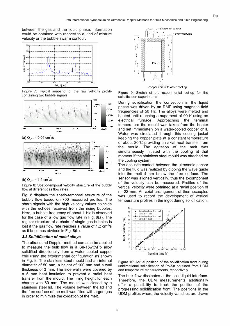
Fig. 8 displays the spatio-temporal structure of the bubbly flow based on 700 measured profiles. The sharp signals with the high velocity values coincide with the echoes received from the rising bubbles. Here, a bubble frequency of about 1 Hz is observed for the case of a low gas flow rate in Fig. 8(a). The regular structure of a chain of single gas bubbles is lost if the gas flow rate reaches a value of 1.2 cm3/s as it becomes obvious in Fig. 8(b). 3.3 Solidification of metal alloys The ultrasound Doppler method can also be applied to measure the bulk flow in a Sn-15wt%Pb alloy solidified directionally from a water cooled copper chill using the experimental configuration as shown in Fig. 9. The stainless steel mould had an internal diameter of 50 mm, a height of 100 mm and a wall thickness of 3 mm. The side walls were covered by a 5 mm heat insulation to prevent a radial heat transfer from the mould. The filling height for each charge was 60 mm. The mould was closed by a stainless steel lid. The volume between the lid and the free surface of the melt was filled with argon gas
Figure 9: Sketch of the experimental set-up for the
e convection in the liquid solidification experiments
During solidification thphase was driven by an RMF using magnetic field frequencies of 50 Hz. The alloys were melted and heated until reaching a superheat of 90 K using an electrical furnace. Approaching the terminal temperature the mould was taken from the heater and set immediately on a water-cooled copper chill. Water was circulated through this cooling jacket keeping the copper plate at a constant temperature of about 20°C providing an axial heat transfer from the mould. The agitation of the melt was simultaneously initiated with the cooling at that moment if the stainless steel mould was attached on the cooling system. The acoustic contact between the ultrasonic sensor and the fluid was realized by dipping the wave guide into the melt 4 mm below the free surface. The sensor was aligned vertically, thus the z-component of the velocity can be measured. Profiles of the vertical velocity were obtained at a radial position of r = 22 mm. An axial arrangement of thermocouples was used to record the development of vertical temperature profiles in the ingot during solidification.
0 20 40 60 80 100 120 140 160 180 200 220 2400
5
10
15
20
25
30
35
40
45
50 thermal analysis, B = 1 mT UDV, B = 1 mT thermal analysis, B = 2 mT UDV, B = 2 mT
front
pos
ition
[mm
]
freezing time [s]
Figure 10: Actual position of the solidification ng
ce.
front duriunidirectional solidification of Pb-Sn obtained from UDM and temperature measurements, respectively
The bulk flow dissipates at the solid-liquid interfaTherefore, the UDM measurements additionally offer a possibility to track the position of the progressing solidification front. The positions in the UDM profiles where the velocity vanishes are drawn in order to minimize the oxidation of the melt.
Top 6th International Symposium on Ultrasonic Doppler Methods for Fluid Mechanics and Fluid Engineering
5
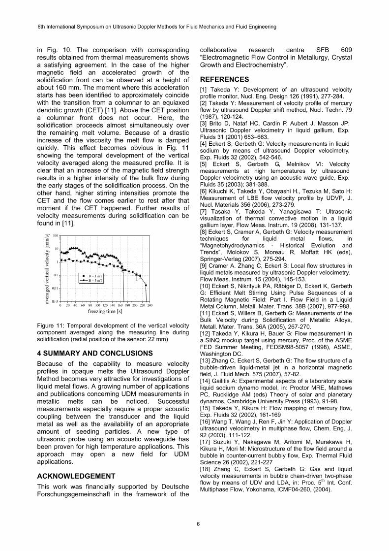
in Fig. 10. The comparison with corresponding results obtained from thermal measurements shows a satisfying agreement. In the case of the higher magnetic field an accelerated growth of the solidification front can be observed at a height of about 160 mm. The moment where this acceleration starts has been identified to approximately coincide with the transition from a columnar to an equiaxed dendritic growth (CET) [11]. Above the CET position a columnar front does not occur. Here, the solidification proceeds almost simultaneously over the remaining melt volume. Because of a drastic increase of the viscosity the melt flow is damped quickly. This effect becomes obvious in Fig. 11 showing the temporal development of the vertical velocity averaged along the measured profile. It is clear that an increase of the magnetic field strength results in a higher intensity of the bulk flow during the early stages of the solidification process. On the other hand, higher stirring intensities promote the CET and the flow comes earlier to rest after that moment if the CET happened. Further results of velocity measurements during solidification can be found in [11].
0 20 40 60 80 100 120 140 160 180 200 220 2401E-3
0.01
0.1
1
10
100
B = 1 mT B = 3 mT
aver
aged
ver
tical
vel
ocity
[mm
/s]
freezing time [s]
Figure 11: Temporal development of the vertical velocity
4 SUMMARY AND CONCLUSIONS re velocity
ACKNOWLEDGEMENT upported by Deutsche
REFERENCES elopment of an ultrasound velocity
ry
n P, Aubert J, Masson JP:
locity measurements in liquid
Melnikov VI: Velocity
ayashi H., Tezuka M, Sato H:
awa T: Ultrasonic
nt
: Local flow structures in
kert K, Gerbeth
easurement in
rt S, Gerbeth G: The flow structure of a
a laboratory scale
ow,
Y: Application of Doppler
gawa M, Aritomi M, Murakawa H,
quid
component averaged along the measuring line during solidification (radial position of the sensor: 22 mm)
Because of the capability to measuprofiles in opaque melts the Ultrasound Doppler Method becomes very attractive for investigations of liquid metal flows. A growing number of applications and publications concerning UDM measurements in metallic melts can be noticed. Successful measurements especially require a proper acoustic coupling between the transducer and the liquid metal as well as the availability of an appropriate amount of seeding particles. A new type of ultrasonic probe using an acoustic waveguide has been proven for high temperature applications. This approach may open a new field for UDM applications.
This work was financially sForschungsgemeinschaft in the framework of the
collaborative research centre SFB 609 “Electromagnetic Flow Control in Metallurgy, Crystal Growth and Electrochemistry”.
[1] Takeda Y: Devprofile monitor, Nucl. Eng. Design 126 (1991), 277-284. [2] Takeda Y: Measurement of velocity profile of mercuflow by ultrasound Doppler shift method, Nucl. Techn. 79 (1987), 120-124. [3] Brito D, Nataf HC, CardiUltrasonic Doppler velocimetry in liquid gallium, Exp. Fluids 31 (2001) 653–663. [4] Eckert S, Gerbeth G: Vesodium by means of ultrasound Doppler velocimetry, Exp. Fluids 32 (2002), 542-546. [5] Eckert S, Gerbeth G, measurements at high temperatures by ultrasound Doppler velocimetry using an acoustic wave guide, Exp. Fluids 35 (2003); 381-388. [6] Kikuchi K, Takeda Y, ObMeasurement of LBE flow velocity profile by UDVP, J. Nucl. Materials 356 (2006), 273-279. [7] Tasaka Y, Takeda Y, Yanagisvisualization of thermal convective motion in a liquid gallium layer, Flow Meas. Instrum. 19 (2008), 131-137. [8] Eckert S, Cramer A, Gerbeth G: Velocity measuremetechniques for liquid metal flows, in “Magnetohydrodynamics - Historical Evolution and Trends”, Molokov S, Moreau R, Moffatt HK (eds), Springer-Verlag (2007), 275-294.[9] Cramer A. Zhang C, Eckert Sliquid metals measured by ultrasonic Doppler velocimetry, Flow Meas. Instrum. 15 (2004), 145-153. [10] Eckert S, Nikrityuk PA, Räbiger D, EcG: Efficient Melt Stirring Using Pulse Sequences of a Rotating Magnetic Field: Part I. Flow Field in a Liquid Metal Column, Metall. Mater. Trans. 38B (2007), 977-988. [11] Eckert S, Willers B, Gerbeth G: Measurements of the Bulk Velocity during Solidification of Metallic Alloys, Metall. Mater. Trans. 36A (2005), 267-270. [12] Takeda Y, Kikura H, Bauer G: Flow ma SINQ mockup target using mercury, Proc. of the ASME FED Summer Meeting, FEDSM98-5057 (1998), ASME, Washington DC. [13] Zhang C, Eckebubble-driven liquid-metal jet in a horizontal magnetic field, J. Fluid Mech. 575 (2007), 57-82. [14] Gailitis A: Experimental aspects of liquid sodium dynamo model, in: Proctor MRE, Mathews PC, Rucklidge AM (eds) Theory of solar and planetary dynamos, Cambridge University Press (1993), 91-98. [15] Takeda Y, Kikura H: Flow mapping of mercury flExp. Fluids 32 (2002), 161-169 [16] Wang T, Wang J, Ren F, Jinultrasound velocimetry in multiphase flow, Chem. Eng. J. 92 (2003), 111-122. [17] Suzuki Y, NakaKikura H, Mori M: Microstructure of the flow field around a bubble in counter-current bubbly flow, Exp. Thermal Fluid Science 26 (2002), 221-227 [18] Zhang C, Eckert S, Gerbeth G: Gas and livelocity measurements in bubble chain-driven two-phase flow by means of UDV and LDA, in: Proc. 5th Int. Conf. Multiphase Flow, Yokohama, ICMF04-260, (2004).
6th International Symposium on Ultrasonic Doppler Methods for Fluid Mechanics and Fluid Engineering
6