Valve terminal type 03 - Festo USA · • In the case of type 03 valve terminals: - pneumatic...
493
Programmable valve terminals type 03 with control block SB 50 / SF 50 Manual 174 830 9706 SIMATIC Integrated
Transcript of Valve terminal type 03 - Festo USA · • In the case of type 03 valve terminals: - pneumatic...

Programmable valve terminals type 03with
control block SB 50 / SF 50
Manual
174
830
9706
SIMATICIntegrated

TN 350 651

Authors: Uwe GräffSiegfried Rechenberger
Edited by: PV-IIP
Layout: Festo KG, PV-IIP
Typesetting: PV-IIP/Rb
4th edition, December 1997
1997 Festo AG & Co., D-73 726 Esslingen 1
The copying, distribution and utilization of this docu-ment as well as the communication of its contents toothers without expressed authorization is prohibited.Offenders will be held liable for the payment of damages.All rights reserved, in particular the right to carry outpatent, utility model or ornamental design registration.
prin
ted
on 1
00%
rec
ycle
d pa
per
PN 350651
VISB - 50
E0n I

Order No.: 174 829
Titel: MANUAL
Designation: P.BE-SB50-03-GB
SIMATIC®, STEP®, SINEC® and COROS® are regis-tered trademarks of Siemens AG.
VISB - 50
II E0n

Programmable valve terminals
Many control tasks involving mainly pneumatic finalcontrol elements (zylinders etc.) can be automatedwithout the need for a control cabinet. An integral pro-grammable controller with the command set andrange of functions of SIMATIC mini controllers allowsprogramming to be carried out easily using familiartools.
SIEMENS, the market leader in PLC technology andFESTO, the market leader in pneumatics, haveworked together to offer the market a perfect solution.
VISB - 50
E0n III

Summary of parts
Part 1 Basic principles of installationcontains information which is not dependent on thetype of valve terminal or on the node selected.
Part 2a Valve terminal type 02System description of valve terminal type 02, contains all necessary information specifically for thistype of terminal.
Part 2b Valve terminal type 03System description of valve terminal type 03,contains all necessary information specifically for thistype of terminal.
Part 3 System description of the SB 50contains all relevant PLC information irrespective ofthe type of valve terminal.
Part 4 System description of the SF 50 as mastercontains additional information required for using thePROFIBUS-DP.
Part 5 System description of the SF 50 as DP slavecontains additional information required for using theSF 50/DP-Slave (SL50)
Part 6 Appendixcontains additonal information on commands, abbre-viations, accessories, literature, etc.
VISB - 50
IV E0n
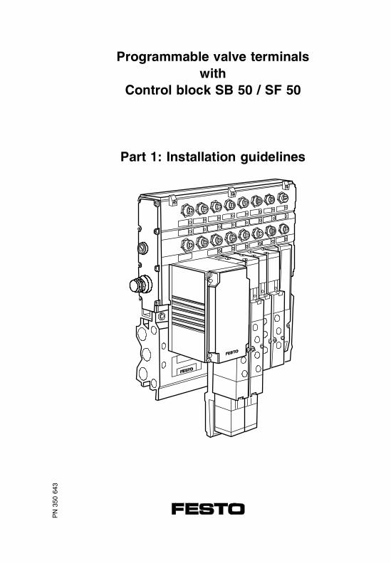
Programmable valve terminalswith
Control block SB 50 / SF 50
Part 1: Installation guidelines
PN
350
643

PN 350 643 is shown in: Manual 174826
Manual 174827
Manual 174828

1.1 USER INSTRUCTIONS
PN
350
643
VISB - 50 1.1 User instructions
9706 1-1
Contents
1.1 IMPORTANT USER INSTRUCTIONS
Danger categories ...............................................1-3
Pictograms ...........................................................1-4
Instructions for this manual .................................1-5
VISB - 50 1.1 User instructions
1-2 9706

1.1 IMPORTANT USER INSTRUCTIONS
Danger categories
This description contains instructions concerningpossible dangers that can occur when using the pro-grammable valve terminal with the control block SB 50.
A distinction is made between the following instruc-tions:
WARNINGThis means that physical or material damage canoccur if these instructions are not observed.
CAUTIONThis means that material damage can occur if these instructions are not observed.
PLEASE NOTEThis means that this instruction must also be observed.
VISB - 50 1.1 User instructions
9706 1-3
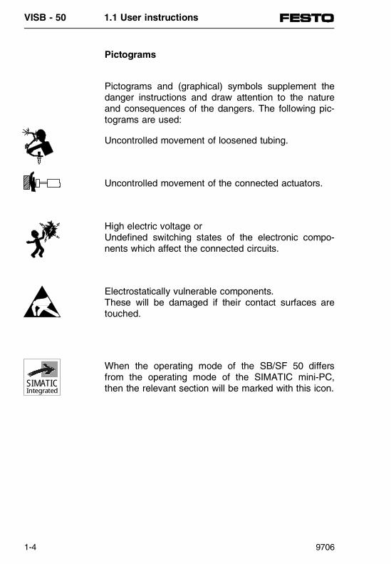
Pictograms
Pictograms and (graphical) symbols supplement thedanger instructions and draw attention to the natureand consequences of the dangers. The following pic-tograms are used:
Uncontrolled movement of loosened tubing.
Uncontrolled movement of the connected actuators.
High electric voltage orUndefined switching states of the electronic compo-nents which affect the connected circuits.
Electrostatically vulnerable components.These will be damaged if their contact surfaces aretouched.
When the operating mode of the SB/SF 50 differsfrom the operating mode of the SIMATIC mini-PC,then the relevant section will be marked with this icon.SIMATIC
Integrated
VISB - 50 1.1 User instructions
1-4 9706

Instructions for this manual
This manual uses the following product-specific abbreviations:
Specialist pneumatic, electronic and programmingterms are explained in the glossary.
Abbreviation MeaningTerminal or valve terminal
Programmable valve terminalwith control block SB 50 / SF 50 with/without electrical I/Os
Node Control block SB / SF 50IQI/Q
InputOutputInput and/or output
VISB - 50 1.1 User instructions
9706 1-5

Programmable valve sensor terminals generally con-sist of the following components.• Nodes with control block SB 50 or SF 50• In the case of type 02 valve terminals:
sub-base corresponds to the number of valves• In the case of type 03 valve terminals:
- pneumatic modules- electrical modules
PLEASE NOTE
• Information concerning the terminal types 02and 03 can be found in sections 2a and 2b inthis manual, depending on your order.
• The majority of the drawings in this manual arebased on a valve terminal type 03 with fourpneumatic terminal blocks and four input/output modules.
Fig. 1/1: Standard configuration for the drawing
VISB - 50 1.1 User instructions
1-6 9706

1.2 SYSTEM SUMMARY
PN
350
643
VISB - 50 1.2 System summary
9706 1-7

Contents
1.2 SYSTEM SUMMARY
Programmable valve terminal..............................1-9
Valve terminal in standalone operating mode (SB 50) ....................................1-10
Valve terminal in master operating mode (SF 50) ....................................1-12
Programming tools.............................................1-14
Programming software STEP 5 ........................1-14
Parameter software COM ET200 WINDOWS / COM PROFIBUS .........................1-15
Terminal-summary .............................................1-16
Valve terminals with analogue modules............1-18
Valve terminal with AS-i master ........................1-20
Valve terminal in slave operating mode............1-22
VISB - 50 1.2 System summary
1-8 9706

1.2 SYSTEM SUMMARY
Programmable valve terminals
The SB 50 control block includes a SIMATIC® PLCtherefore making the FESTO valve terminals types 02and types 03 into programmable valve terminals.There are two forms for the control blocks:• SB 50-02 for valve terminal type 02• SB 50-03 for valve terminal type 03
Independent automation tasks require the use of sen-sors. These can be directly connected to the valveterminal. Regardless of the type of valve terminal,there are various numbers of input modules available.In addition, electrical outputs are available. Thismeans that independent automation tasks can besolved on-site.
Advantages of the programmable valve terminal withcontrol block SB 50 • Built-in SIMATIC® PLC• Protection class IP 65 is fulfilled – no control
cabinet required• Simple equipment layout with independent control
on site• Low wiring costs• Pre-assembled valves• Hard-wired valve solenoid coil• Central exhaust• Inspected unit• Electrical inputs e.g. for sensors• Electrical outputs, e.g. for electrical actuators• Further advantages, depending on the type of
valve terminal
VISB - 50 1.2 System summary
9706 1-9

The built-in PLC represents a SIMATIC® with thecommand set for mini control systems. The pro-grammable valve terminals can be operated with thefollowing:• Pushbutton panel (START/STOP)• Keyboard with text display (OP5)
For programming you will require a PC or one of thereliable programming tools PG685 to PG770 and theSIMATIC programming software STEP 5®. The PC orprogrammer must be connected to the diagnostic in-terface of the control blocks.
PLEASE NOTEThe standard programming cable from Siemenscan be used for the connection. When using a PCas a programming tool, an active interface conver-tor V.24 ⇔ TTY is required.
The following programming languages are available:• CSF (control system function chart)• LDR (Ladder diagram)• STL (Statement List)
The following two diagrams show a system summary:
Valve terminal in standalone operating mode (SB 50)
A valve terminal type 02 fitted with a control block SB 50-02, or a valve terminal type 03, fitted with a control block SB 50-03, forms the independentlyoperating controller.
VISB - 50 1.2 System summary
1-10 9706

Operation is implemented either• by a control panel with keys, which is connected to
the free inputs and outputsor
• by a control panel with COROS® OP5, which isconnected to the diagnostic interface of the controlblock. In this case, the OP5 is programmed via thesoftware COM TEXT or PROTOOL/Lite.
S I E M E NS
RUN
S T O P
BF
24V DC F US E
L2-DP
PG
12 14
S T E P 5
C O MP R O F I B U S
P R O T O O LL I T E
Operation + monitoring
ProgrammerPG685 ... PG770
Start/Stop buttons
Control unit OP5 in housing
Valve terminal type 03 asindependent controller
Fig. 1/2: System structure with SB 50
VISB - 50 1.2 System summary
9706 1-11

Valve terminal in master operating mode (SB 50)
A valve terminal type 02 fitted with a control block SF 50-02, or a valve terminal type 03, fitted with acontrol block SF 50-03, forms the central operatingcontroller as the field bus master.
Operation is implemented either• by a control panel with keys, which is connected to
the free inputs and outputsor
• by a control panel with OP5 or OP15 , which isconnected to the diagnostic interface of the controlblock. In this case, the OPx is programmed via thesoftware COM TEXT or PROTOOL/Lite.
Slaves of the PROFIBUS-DP can include:• Field bus valve terminals with FB9/FB13,
types 02-06 and type 10 from Festo• The decentralized peripherals of the
SIMATIC ET 200• PROFIBUS-DP-slaves of other manufacturers
A PG720-770 programmer or a PC should be usedfor programming. The programmers PG720/740/760are fitted as standard with the MPI interface, whichcan be used for the PROFIBUS-DP-configuration. Theinterface component for the PROFIBUS-DP-configura-tion can be retro-fitted to the programmersPG730/750/770 or a PC.
VISB - 50 1.2 System summary
1-12 9706
12 14 12 14
SIEM EN S
R U N
ST O P
BF
24 VDC F U SE
L 2- D P
PG
12 14
STEP5
COMPROFIBUS
PROTOOL LITE
PROFIBUS-DP
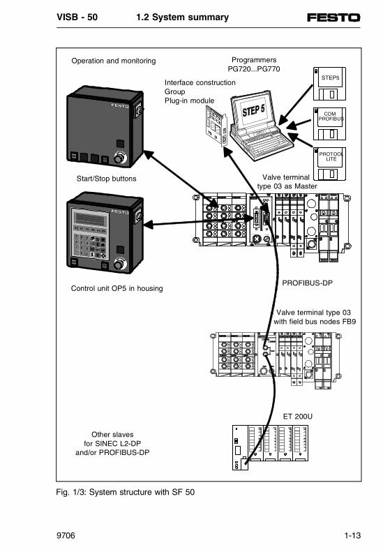
Operation and monitoring ProgrammersPG720...PG770
Valve terminal type 03 as Master
Valve terminal type 03 with field bus nodes FB9
ET 200U
Start/Stop buttons
Control unit OP5 in housing
Interface constructionGroupPlug-in module
Other slavesfor SINEC L2-DP
and/or PROFIBUS-DP
Fig. 1/3: System structure with SF 50
VISB - 50 1.2 System summary
9706 1-13

Programmers
The following programmers can be used for programgeneration in the SB 50 control block:• PG685, PG710 (SB 50 only)
• PG720-770• PC with programming software STEP 5
Programming software STEP 5
STEP 5 is the programming language for applicationprogramms using the SIMATIC S5 automation unitand the FESTO valve terminals with built-in SIMATIC-PLC. The application programms can be displayed in• CSF (Control system function chart)
• LDR (Ladder diagram)• STL (Statement List)
STEP 5
I3.2
& >=1
Q 1.6
I4.3
I2.3
CSF
( )
LDR
I2.3 I4.3 Q1.6
I3.2
A I2.3A I4.3Q I3.2= Q1.6
STL
VISB - 50 1.2 System summary
1-14 9706

Parameter software COM ET 200 WINDOWS / COM PROFIBUS
The addresses of the inputs and outputs of thedecentralized peripheral devices are determined bymeans of the parameter software COM ET 200 WIN-DOWS / COM PROFIBUS. The plug-in module, whichmust be installed in the PG/PC, writes into the EE-PROM memory, which is integrated in the SIMATIC-PLC.
The software ’Festo SF 50 Download’ can be used asan alternative to the interface component (see chapter4.1).
COMPROFIBUS
VISB - 50 1.2 System summary
9706 1-15

Terminal-summary
The control blocks SB 50 and SF 50 can be operatedwith valve terminals type 02 and type 03. The controlblocks SB 50 then allow independent control of thevalve terminal.
When the SF 50 control block is used as the masterof a PROFIBUS-DP field bus system, extensive andcomplex systems can be controlled.
Valve terminal type 02
- Component size 1/8 inch, 1/4 inch- 4 / 6 / 8 / 10 / 12 / 14 / 16 valves- Valve types: single solenoid, double pilot valve,
mid-position valve open, blocked, exhausted- with or without separate supply of
auxiliary pilot air- 2 inputs per valve location- 2 additional inputs- 2 additional electrical outputs
SI EM ENS
R UN BF
L 2-DP
P G
S TO P
Fig. 1/4: Example of a valve terminal type 02 with SF 50
VISB - 50 1.2 System summary
1-16 9706

Valve terminal type 03
- Component size 4 mm (MIDI), 7 mm (MAXI)- Valve types: single solenoid, double pilot valve,
mid-position valve open, blocked, exhausted- max. 26 valve coils- max. 64 outputs, including coils- max. 56 inputs- max. 12 electrical modules
SIEMENS
RUN
ST OP
BF
24VDC F USE
L 2-DP
PG
Fig. 1/5: Example of a valve terminal type 03 with SF 50
VISB - 50 1.2 System summary
9706 1-17
Valve terminals with analogue modules
In many automation tasks, analogue signals are usedin addition to digital inputs and outputs.
There are special analogue modules available forthese tasks for the programmable valve terminals withSB 50 or SF 50/DP-Slave. These modules can beused to process analogue input signals such as set-point specifications and actual value response as wellas analogue outputs for actuation of final control ele-ments.
These analogue modules come in the following versions:• Universal
(with either current or voltage interface)- current-loop interface 4...20 mA, cut-off frequency 116 Hz- voltage-loop interface 0...10 V, cut-off frequency 116 Hz
• Proportional(adapted to the actuation of proportional valves;4...20 mA, cut-off frequency 100 Hz).
Using a programmable valve terminal with analogueprocessing offers the following advantages:- preliminary processing of analogue signals directly
on the process- proportional valves can easily be connected- short cables, therefore less interference.
VISB - 50 1.2 System summary
1-18 9706

PN
350
643
IP
S I E M E NS
RUN
S T O P
BF
24V DC F US E
L2- DP
P G
Analogue modules
Proportionalvalve (e.g. MPPE,MPYE)
Actuator with variable contact pressure or feed (speed)
AnalogueI/Osuniversalmodule
Operation and monitoringProgramming(inc. analogue I/Os)
Valve terminalswith analogue I/Os
Analogue I/Osproportional module
Fig. 1/6: System summary: Valve terminals with analogue modules
VISB - 50 1.2 System summary
9706 1-19

Valve terminal with AS-i master
The pneumatic final control elements are centrallycontrolled in many machines and units. Using the ac-tuator sensor interface allows simple installation of thedigital final control elements on the programmablevalve terminal with SF 50 and SF 50/DP-Slave.
Using a programmable valve terminal with AS-i master offers the following advantages:
- No restriction in using the SB 50 in standalone operating mode.
- Easy-to-install connection of pneumatic final controlelements and sensors in systems distributed overwide areas.
- Scope for expansion.- Pneumatic installation adapts to the mechanical
construction of the machine or system.- Tubing is kept short.- Simple configuration of AS-i-network with the
addressing device.
VISB - 50 1.2 System summary
1-20 9706

SIEMEN S
R U N
S T O P
B F
2 4VDC F US E
L 2 - DP
PG
Operation and monitoring
Programming + Configuring (inc. AS-i)
Valve terminalwith AS-i master
AS-i slave valve terminaltype 03
AS-i slave I/O module 4I
max. 31 AS-i-bus slaves
AS-i slave I/O module 2I2O
AS-i-addressing device
Fig. 1/7: System summary: Valve terminal with AS-i master
VISB - 50 1.2 System summary
9706 1-21

Valve terminal in slave operating mode
A valve terminal with an SF 50/DP-Slave connectedto the field bus as a slave controls the operating unitsof the machine itself and communicates with a higher-order master via the field bus.
When using the programmable valve terminal as aslave, the mechanical construction of a machine or asystem can be simulated by distributing the PLCs(programmable logic controllers). All standalone mo-dules or function units then have their own controlprograms with which subranges can be controlled.
The use of programmable valve terminals as slavesoffers the following advantages:- No restriction in using the SF 50 in standalone oper-
ating mode.- Modular construction of the system/machine is
possible.- Function modules of the system or machine can be
linked together individually.- User-friendly partial commissioning possible.- High system availability due to standalone
subranges.- Local operation and monitoring is possible.
VISB - 50 1.2 System summary
1-22 9706

Higher-order master
PLC PC/I-PC
Local operation and monitoring(SF 50 as active DP-slave)
Programmablevalve terminals
Slave (active)valve terminal type 03
Slave (active)valve terminal type 02
Slave (active)valve terminal type 03
Fig. 1/8: System summary: Valve terminal in slave operating mode
VISB - 50 1.2 System summary
9706 1-23

VISB - 50 1.2 System summary
1-24 9706

1.3 SYSTEM LIMITS ANDPLANNING ASPECTS
PN
350
643
VISB - 50 1.3 System limits and planning aspects
9706 1-25

Contents
1.3 SYSTEM LIMITS AND PLANNING ASPECTS
- System limits ...................................................1-27
- Planning aspects of valve terminals type 03.............................................................1-29
- Planning aspect 1 Common power supply for all outputs ............1-30
- Planning aspect 2 Separate power supply for single high-voltage output modules ...........................1-32
- Planning aspect 3 Possible combinations of I/O modules............1-34
VISB - 50 1.3 System limits and planning aspects
1-26 9706

1.3 SYSTEM LIMITS AND PLANNING ASPECTS
System limits
The theoretical structure of a complete system withprogrammable valve terminals can appear as follows:• SF 50 as master with up to
56 local inputs and64 local outputs
• 16 field bus slaves as intelligent slaves or decentralized peripherals (e.g. field bus valve terminals)
or
• SB 50 or SF 50/DP-Slave with up to56 local inputs and64 local outputs
• AS-i master with up to 31 AS-i slaves (max. 128 inputs and 128 outputs)
• Analogue input and output modules(max. 12 channels)
• Operating and monitoring units.
VISB - 50 1.3 System limits and planning aspects
9706 1-27

In practice, the number of units, or inputs and outputs,mentioned above is limited by the size of the usermemory (16 + 4 kByte) and the cycle time (3...5 ms/1 kstatements). The number of controllable inputs and outputs is al-ways dependent on the complexity of the controlproblem and the use of special peripherals, like e.g.human machine interface (HMI), which require addi-tional user memory space.
Guideline value for a rapid "average" application:approx. 300 I/Os (including HMI units)
PLEASE NOTEThe number of controllable inputs and outputs is al-ways dependent on the complexity of the controltask and the use of special peripheral equipment.For any larger applications, the memory require-ment should be estimated on an individual basis.
VISB - 50 1.3 System limits and planning aspects
1-28 9706

Planning aspects of valve terminals type 03
This chapter contains some advice on the followingplanning aspects for modular valve terminals:• Planning aspect 1
Common voltage supply to all outputs; i.e. theEMERGENCY STOP function for all outputs is implemented via pin 2 of the node/adapter block(valves and electrical modules).
• Planning aspect 2Separate voltage supplies for individual high-voltage output modules; i.e. the auxiliary powersupply in combination with the high-voltage outputsenables operation independent of the EMER-GENCY STOP function.
• Planning aspect 3Possible combinations of I/O modules.Instructions for planning the sequence in which I/Omodules can be fitted and combined on a valve ter-minal.
VISB - 50 1.3 System limits and planning aspects
9706 1-29

Planning aspect 1 Common voltage supply for all outputs
With this aspect, all the components of the valve ter-minal are supplied with 24 V via pins 1 and 2 of thenode/adapter blocks.• Pin 1: 24 V (+/− 25 %), max. 2.2 A operating
voltage for the internal electronics of the node andall I/O modules. 24V DC power supply to all inputs/sensors (PNP and NPN).
• Pin 2: 24 V (+/− 10 %), max. 10 A operating voltage for the valves and electrical outputs.Please note that when the valves are switched off(e.g. during EMERGENCY STOP) all the electricaloutputs will also be switched off.
VISB - 50 1.3 System limits and planning aspects
1-30 9706

Advantages:• Easy installation: − simply involves connecting up
a power supply unit.• All outputs on the valve terminal are switched off
at the hardware level when EMERGENCY STOPis activated (failsafe).
Disadvantages:• It is not possible to implement a different EMER-
GENCY STOP process with which certain electri-cal outputs remain active.
12
3
4
All outputs can bedisconnected duringEMERGENCY STOP
Power supply for node/adapter block(Pin 1+2) with EMERGENCY STOP
Electrical outputs Outputs of valves
Fig 1/9: Common voltage supply of all outputs (example)
VISB - 50 1.3 System limits and planning aspects
9706 1-31
Planning aspect 2 Separate voltage supply for single high-voltageoutput modules
This involves fitting at least one module for a 24 Vauxiliary power supply to the left side of the node.This module provides electrical isolation of the I/Os.The high-voltage output modules are fitted to the leftside of the auxiliary power supply unit and are onlysupplied from their 24 V power source. A mixture ofnegative and positive switching high-voltage outputmodules can be fitted.
Voltage supply via the node:• Pin 1: 24 V (+/− 25 %), max. 2.2 A operating
voltage for the internal electronics of the node andall I/O modules. 24V DC power supply to all in-puts/sensors (PNP and NPN).
• Pin 2: 24 V (+/− 10 %), max. 10 A operating voltage for the valves and only for the electricaloutputs (PNP; 0.5 A). Please note that when thevalves are switched off, (e.g. during EMERGENCYSTOP) only these electrical outputs will beswitched off (PNP; 0.5 A).
Voltage supply via the auxiliary power supply:• Terminal 2: 24 V (+/− 25 %), max. 25 A operating
voltage for all high-voltage outputs (PNP or NPN, 2 A) mounted to the left of the relevant auxiliarypower supply (power supply ends with last high-voltage output module).
Note:Due to the auxiliary power supply, the operating volt-age of the high-voltage outputs is entirely separatefrom pin 2 on the node.The "normal" output modules (PNP; 0.5 A) fitted to theleft of the last high-voltage output module are again sup-plied via pin 2 on the node.
VISB - 50 1.3 System limits and planning aspects
1-32 9706

Advantages:• Additional 25 A per auxiliary supply are available
for loads with high current consumption (e.g. hy-draulic valves).
• Modules with four high-voltage outputs (HC-OUTPUT, each with optional 2 A PNP orNPN): these can be supplied with power to the leftof the auxiliary power supply.
• Electric high-voltage outputs to the left of theauxiliary power supply can remain active duringEMERGENCY STOP.
• Several auxiliary power supplies per terminal are possible.
Disadvantages:• An auxiliary power supply unit occupies the space
of one I/O module (max. 12 modules).• If the high-voltage outputs to the left of the auxi-
liary power supply are also to be switched off during EMERGENCY STOP, it may be necessaryto provide additional appropriate installations.
4
2
3
4
12
3
4
Electrical outputs
Valves/electr. outputs can be dis-connected whenEMERGENCYSTOP is activated
Power supplyfor auxiliarypower supply(without EMER-GENCY STOP)
Outputsvalves
Power supply for node/adapter block(Pin 1+2) with EMERGENCY STOP
Electrical outputs
High-voltage outputs (withoutEMERGENCY STOP)
+ 24 V
0 V
PE
Fig. 1/10: Separate voltage supply to all outputs (example)
VISB - 50 1.3 System limits and planning aspects
9706 1-33

Planning aspect 3Possible combinations of I/O modules
A wide range of universal and special I/O modules isavailable for modular valve terminals and these canbe combined in virtually any sequence. Take due account during the planning stage, or whenconverting the terminals, of the permitted combina-tions. This rule always applies: maximum of 12 electri-cal modules per terminal.
This point applies to individual electrical modules:• Digital PNP modules (4I, 8I and 4O) in any
combination and in any position (5).• Digital NPN input modules (4I, 8I) in any combina-
tion and in any position (5).• Analogue I/O modules (PROP; UNIVERSAL)
in any combination and in any position (4).• Auxiliary power supply units: always fitted to any
position (3).• Module with high voltage outputs (HC-OUTPUT,
PNP or NPN) only to the left of an auxiliary powersupply, there combined as required (2).
• The AS-i master must always be fitted at the farleft (1).
VISB - 50 1.3 System limits and planning aspects
1-34 9706

1 2* 2 2 3 4 4 2* 3 5 5 6
Modules2...5any
* High-voltage power supply (grey connection) ends after the last HC output module
max.1 AS-imaster-module
Modules2...5any*
Modules2...5any*
Possible combinations
Modules:
1 = AS-i master 4 = Analogue module2 = HC output (PNP/NPN) 5 = I/O module 4I, 8I (PNP/NPN) or 4O PNP3 = Auxiliary power supply 6 = Nodes
Fig. 1/11: Possible combinations of the electrical I/O modules (example)
VISB - 50 1.3 System limits and planning aspects
9706 1-35

VISB - 50 1.3 System limits and planning aspects
1-36 9706
1.4 INSTALLATION
PN
350
643
VISB - 50 1.4 Installation
9706 1-37

Contents
1.4 INSTALLATION
General remarks ................................................1-39
Connecting up cable to plug/socket ..................1-40
Connecting up operating voltage.......................1-43
Operating voltage connection............................1-44
Cable length and wire cross section .................1-48
Connecting up electrical inputs .........................1-54
Valve terminal type 02.......................................1-55
Valve terminal type 03.......................................1-56
Examples of input circuitry ................................1-57
Connecting up electrical outputs .......................1-59
Valve terminal type 02.......................................1-60
Valve terminal types 03 .....................................1-61
Examples of output circuitry ..............................1-62
Duo cable...........................................................1-63
Designation of inputs and outputs.....................1-65
Valve terminal type 02.......................................1-65
Valve terminal type 03.......................................1-65
Field bus connector assembly FBS-SUB-9-GS-9...............................................1-66
Connection instructions for valve terminals.......1-68
Connector assembly S-SUB-15-GS-9...............1-69
Connector accessories ......................................1-71
VISB - 50 1.4 Installation
1-38 9706

1.4 INSTALLATION
General remarks
By doing this you will avoid:• Uncontrolled movements of loose tubing.• Undesired movements of connected actuators.• Undefined switching states of the electronics.
WARNINGBefore installation and maintenance work switch offthe following:
• the compressed air supply.
• the operating voltage supply for the electronics (pin 1 of the operating voltage connection)
• th operating voltage supply for the outputs/val-ves (pin 2 of the operating voltage connection)
VISB - 50 1.4 Installation
9706 1-39

Connecting the cable to the plug/socket
Once you have selected suitable cables, connectthem to the plugs/sockets as indicated in steps 1...7below.
1. Open the plug/socket as follows (refer to diagram):
Mains socket:Insert the mains socket in the operating voltageconnection of the valve terminal. Remove the hous-ing from the socket.Remove the connection part from the socket, lo-cated in the operating voltage connection.
Sensor connector/diagnosis socket: Remove the middle knurled nut.
CAUTIONThe position of pins on plugs/sockets differs!
• The connections of the input and output modules are fitted as sockets.
• The operating voltage connections are fitted asplugs.
The Pin allocation can be found in the followingchapter.
VISB - 50 1.4 Installation
1-40 9706

2. Open the strain relief on the rear part of the hous-ing. Finally, feed the cable through as shown inthe diagram.
Permitted cable external diameterThreadedconnector
Cable diameter
Mains socket: PG9PG13.5
6.5...8 mm7.5...11 mm
Sensor connector: PG7 4.0...6.0 mm
3. Remove 5 mm of insulation from the end of the cable.
4. Fit cable strands with cable end sleeve.
5. Connect up the ends of the cables.
6. Replace the connection part back on the housingof the plug/socket and screw both components to-gether. Pull the cable back so that it is not loopedinside the housing.
7. Tighten the strain relief.
Cable
Strain relief
Housing
Sensor Mains socket
Connectionpart
Fig. 12: Individual components of the connector
VISB - 50 1.4 Installation
9706 1-41

VISB - 50 1.4 Installation
1-42 9706

Connecting the operating voltage
WARNINGFor reliable electrical isolation of the operating volt-age complying with VDE 0113, you will require anisolating transformer complying with DIN/VDE 0551with a minimum 4 kV isolation resistance.
CAUTIONThe operating voltage supply of the outputs orvalves (pin 2) must be externally protected with afuse maximum 10 A. By using an external fuse youwill avoid functional damage to the valve terminal inthe event of a short circuit.
Before connecting the operating voltage, please notethe following:• Calculate the total consumption of the valve termi-
nal under the worst operating conditions. In the de-scriptions of the individual valve terminals (Parts2a and 2b) you will find formulae to help with thecalculations. Then select a suitable power packand cables with suitable cross sections.
• Avoid long distances between power supply andvalve terminal. If necessay, calculate the distanceusing the data given below in this chapter. Thegeneral formula is:
Consumption Cable-cross-section
Distance
Pin 1 = 2.2 APin 2 = 10 A max.VB = 24 V
1.5 mm2 ≤ 8 m2.5 mm2 ≤ 14 m
VISB - 50 1.4 Installation
9706 1-43

Operating voltage connection
The connection for the 24 V operating voltages canbe found on the left side of the baseplate in the valveterminals type 02 and on the bottom left edge of thecontrol block in valve terminals type 03.
The following components of the valve terminal aresupplied separately with + 24 V direct voltage (DC)via this connection:• Operating voltage for internal electronics, PLC and
the inputs of the input modules (pin 1: DC + 24 V,Tolerance ± 25 %).
• Operating voltage for outputs of the valves and theoutputs of the output modules (pin 2: DC + 24 V,Tolerance ± 10 %, external fuse with max. 10 A re-quired).
S I EM EN S
RUN BF
L2- DP
PG
S TOP
Operating voltageconnection
Fig. 1/13: Operating voltage connection for valve terminalstype 02
SIEMENS
RUN
STO P
BF
2 4VDC F USE
L2-DP
PG
Operating voltageconnection
Fig. 1/14: Operating voltage connection for valve terminalstype 03
VISB - 50 1.4 Installation
1-44 9706

RecommendationConnect the operating voltage of the outputs andvalves via the EMERGENCY STOP circuit.
The following diagram shows the pin allocation of theoperating voltage connection.
PLEASE NOTEPlease note that when a common power supply isused for pin 1 (electronics and inputs) and pin 2(outputs/valves) the lower tolerance of ≤ 10 % mustbe observed for both electric circuits.
Check the 24 V operating voltage for the outputswhile your system is operating. Ensure that the opera-ting voltage of the outputs remains within the per-mitted tolerances, even during full-power operation.
RecommendationUse a closed-loop power supply unit.
24 V supply forvalves / outputs
0 VPEProtective earth connection (leading contact)
24 V supply forelectronics and inputs
1
4 2
3
Fig. 1/15: Pin allocation operating voltage connection
VISB - 50 1.4 Installation
9706 1-45
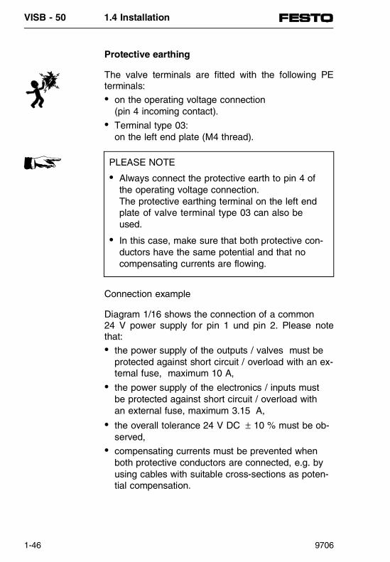
Protective earthing
The valve terminals are fitted with the following PEterminals:• on the operating voltage connection
(pin 4 incoming contact).• Terminal type 03:
on the left end plate (M4 thread).
Connection example
Diagram 1/16 shows the connection of a common 24 V power supply for pin 1 und pin 2. Please notethat:• the power supply of the outputs / valves must be
protected against short circuit / overload with an ex-ternal fuse, maximum 10 A,
• the power supply of the electronics / inputs mustbe protected against short circuit / overload withan external fuse, maximum 3.15 A,
• the overall tolerance 24 V DC ± 10 % must be ob-served,
• compensating currents must be prevented whenboth protective conductors are connected, e.g. byusing cables with suitable cross-sections as poten-tial compensation.
PLEASE NOTE
• Always connect the protective earth to pin 4 ofthe operating voltage connection.The protective earthing terminal on the left endplate of valve terminal type 03 can also beused.
• In this case, make sure that both protective con-ductors have the same potential and that no compensating currents are flowing.
VISB - 50 1.4 Installation
1-46 9706

3 1 2 4
3.15 A
10 A
External fuse
EMERGENCY STOP
Protective grounding terminal at pin 4 rated for 12 A
Interconnecting cablefor potential compen-sation of the earthconnections
AC 230 V
DC 24 V± 10 %
Fig. 1/16: Connection example of a common 24 V power supply and both protective conductors
1
2 A
2 3 4
Electrical outputs
Electrical inputs/sensors
24 V power supply forelectronics without internal fuses
Valves(must be externally protected)
Operating voltage connectionfor valve terminals
Power supply
Fig. 1/17: Internal distribution of the operating voltages
VISB - 50 1.4 Installation
9706 1-47

Cable length and cross section
PLEASE NOTEThe following information assumes a workingknowledge of the information set out in the "Instal-lation" chapters of this manual and is exclusively forthe use of specialists trained in electronics techno-logy.
A load-dependent voltage drop occurs on all threecables in the operating voltage supply to a valve ter-minal. This can lead to the voltage on pin 1 or pin 2of the operating voltage connection falling outside thepermitted tolerance range.
Recommendation:• Avoid long distances between power supply and
valve terminal.• Determine the suitable cable length and cross-
section using the following graphs or formulae.When doing this, note that- the graphs produce approximate values for the
1.5 und 2.5 mm2 cross-sections- The formulae produce exact values for all
cross-sections.
PLEASE NOTEThe following graphs and formulae assume that thecable cross sections of the operating voltage supply(pins 1, 2 and 3) are equal.
VISB - 50 1.4 Installation
1-48 9706

Determined with the use a graph
Proceed as follows:
1. Calculate the maximum current consumption foroutputs/valves (I2).
2. Determine the lowest expected operating voltage(VBmin) of the power supply unit. Take accounthere of:- the load-dependency of the power supply unit.- the fluctuations of the primary supply voltage.
3. Read off the permitted cable length from the rele-vant table for your cross section.Example for 1.5 mm2:VBmin = 22.8 V, I2 = 2 A; Lmax = 25 m
VISB - 50 1.4 Installation
9706 1-49

10A 6A 4A
21,6
22
23
24
25
26
10 20 30 40 50 m
+10%
-10%
26,4
2A
8A
3A
0
VB
min in
Vol
t
Current I2 in amps
Cable length in metres
Cross section 1.5 mm2
V
Fig. 1/18: Permitted cable length of the mains cable with a cross section of 1.5 mm2
21,6
22
23
24
25
26
10 20 30 40 50 m
+10%
-10%
26,4
0
10A 8A
6A
4A
3A
2A
VB
min in
Vol
t
Current I2 in amps
Cable length in metres
Cross section 2.5 mm2
V
Fig. 1/19: Permitted cable length of the mains cable with a cross section of 2.5 mm2
VISB - 50 1.4 Installation
1-50 9706
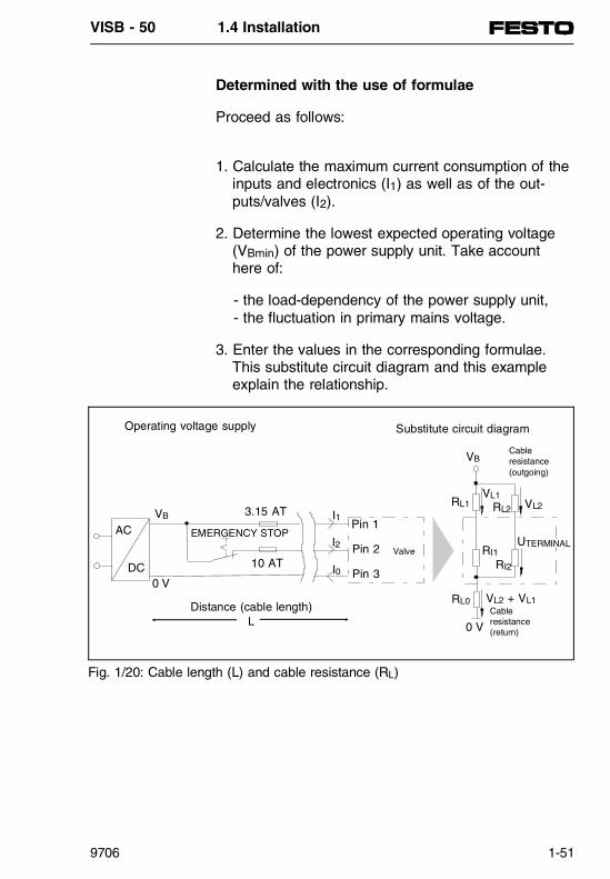
Determined with the use of formulae
Proceed as follows:
1. Calculate the maximum current consumption of theinputs and electronics (I1) as well as of the out-puts/valves (I2).
2. Determine the lowest expected operating voltage(VBmin) of the power supply unit. Take accounthere of:
- the load-dependency of the power supply unit, - the fluctuation in primary mains voltage.
3. Enter the values in the corresponding formulae.This substitute circuit diagram and this example explain the relationship.
AC
DC0 V
VB
EMERGENCY STOP
3.15 AT
10 AT
I1
I2
Pin 1
Pin 2
Pin 3
Valve
RL0
0 V
VL2 + VL1
UTERMINAL
Cableresistance(return)
RI2
RI1
VB
RL1
Cableresistance(outgoing)
VL1VL2RL2
Distance (cable length)L
Operating voltage supply Substitute circuit diagram
I0
Fig. 1/20: Cable length (L) and cable resistance (RL)
VISB - 50 1.4 Installation
9706 1-51

Formula for cable length:
L ≤ (VBmin − VVALVTERM min) ⋅ A ⋅ κCu
2 ⋅ I2 + I1
Where:• VTERMINAL = 24 V ± 10 %,
minimum: VVALVTERMmin ≥ 21.6 V • VBmin = minimum operating voltage supply
(in power supply unit)• Current I1 = Current for electronics and inputs• Current I2 = Current for outputs and valves• A = Cable cross section (uniform e.g. 1.5 mm2)• k = Conductivity of the cables
(uniform e.g. κCu = 56 m
mm 2 ⋅ Ω )
Example: I1 = 1 AI2 = 5 AVB = 24 VVTERMINAL min = 21.6 VkCu = 56
m
mm2 ⋅ Ω
Results:L ≤ 18 m for A = 1.5 mm2
L ≤ 30 m for A = 2.5 mm2
VISB - 50 1.4 Installation
1-52 9706

Empty page for file transfer
VISB - 50 1.4 Installation
9706 1-53

Connection of electrical inputs
By doing this you will avoid:• uncontrolled movements of loose tubing.• undesired movements of connected actuators.• undefined switching states of the electronics.
The input modules of the valve terminal have variousnumbers of inputs available for use. All inputs have apositive logic (PNP inputs).• Valve terminal type 02:
2 inputs per valve locationtogether with 2 inputs per valve terminal
• Valve terminal type 03:Input module with 4 or 8 inputsmax. 56 inputs per valve terminal
WARNINGBefore installation and maintenance work switch offthe following:
• the compressed air supply
• the operating voltage supply for the electronics (pin 1)
• the operating voltage supply for the out-puts/valves (pin 2).
VISB - 50 1.4 Installation
1-54 9706

Valve terminal type 02
WARNINGIf the lower socket is used for two input cables,then the upper socket must remain unused andprotected against dirt with a cover.
PLEASE NOTEIf the lower sockets are used for two inputs, we re-commend that the DUO cable and the accompanyingextension cable are used. A description is given fur-ther in this chapter.
Inputsocket
Pin allocation ofthe sockets
Internal pinconnections
Explanation
Upperrow
Bridge between pin 2 andpin 4
Lower row
Connection between pin2/4 of the upper row andpin 2 of the lower row
Advantage:Two inputs can beconnected to the lowerrow. This results in:- cable reduction - connection of change-
over contact or change-over switch is possible
Fig. 1/21: Pin allocation of inputs in valve terminals type 02
1 2
4 3
24 V(fused) Ix
Ix 0 V
1 2
4 3
24 V(fused) Ix
Ix+1 0 V
1 2
4 3
1
4 3
2
VISB - 50 1.4 Installation
9706 1-55

Valve terminal type 03
The input modules of the valve terminal type 03 havefour or eight inputs available for use.
4-input module 8-input module
Fig. 1/22: Digital input modules (4/8 outputs) for valve terminal type 03
Sockets,each withonedigitalinput
Green LED
Sockets,each withtwodigitalinputs
OnegreenLED oneachdigital input
Connection preferably with DUO cable
4-pin allocation 8-pin allocation
0 0
1
12
similar assignment2345
similar assignment
3 6
7
Fig. 1/23: Pin allocation of the input modules for valve terminal type 03
1
4
3
20 VFree
+ 24 VInput
Ix
1
4
3
20 VFree
+ 24 VInputIx+3
1
4
3
20 VInput
Ix+1
+ 24 V InputIx
1
4
3
2
0 VInputIx+7
+ 24 VInputIx+6
VISB - 50 1.4 Installation
1-56 9706

Examples of input circuitry
Internalstructure
Examples of circuitry
Fig. 1/24: Input module terminal type 02, upper row 4-input module, terminalstype 03
24 V ± 25 %
PLC IxLogic-recognitionIx
1
2
4
30 V
Green LED Ix
Pin 2 and pin 4 are internallyconnected in type 02
Positive switching
Three wiresensor
Pin allocation of type 03
Positive switching
Two wire sensor Contact
VISB - 50 1.4 Installation
9706 1-57

Internalstructure
Examples of circuitry
Fig. 1/25: Input module terminal type 02, lower row 8-input module, terminalstype 03
Logic-recognitionIx+1
GreenLED Ix+1
PLC Ix+1
1
2
4
3
24 V ± 25 %
PLC Ix
Logic-recognition Ix
0 V
GreenLED Ix
Duo cable
Sensor 1 (Ix)Sensor 2 (Ix+1)
Pin allocation of type 03
VISB - 50 1.4 Installation
1-58 9706

Connection of electrical outputs
By doing this you will avoid:• uncontrolled movements of loose tubing.• undesired movements of connected actuators.• undefined switching states of the electronics.
The valve terminal has various numbers of outputsavailable for use. All outputs have a positive logic(PNP outputs).• Valve terminal type 02
2 additional electrical outputs per valve terminal.• Relay plates with one or two relay contacts can be
fitted on the valve locations. They provide floatingcontacts.
• Valve terminal type 03Output modules with 4 outputsmax. 64 outputs per valve terminal, inc. coils,max. 10 A total current
WARNING
• Before installation and maintenance work switchoff the following:
• the compressed air supply.
• the operating voltage supply for the electronics(pin 1)
• the operating voltage supply for the out-puts/valves (pin 2)
VISB - 50 1.4 Installation
9706 1-59
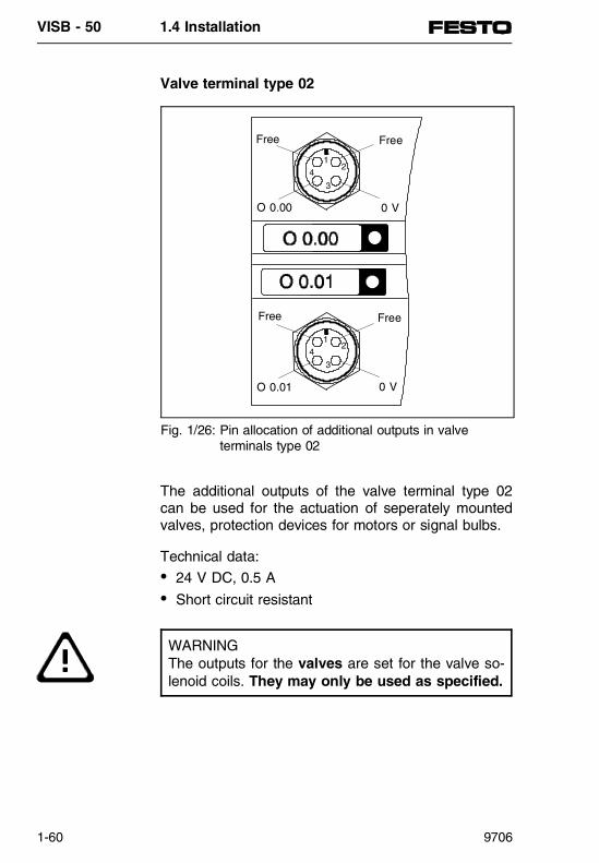
Valve terminal type 02
The additional outputs of the valve terminal type 02can be used for the actuation of seperately mountedvalves, protection devices for motors or signal bulbs.
Technical data:• 24 V DC, 0.5 A• Short circuit resistant
WARNINGThe outputs for the valves are set for the valve so-lenoid coils. They may only be used as specified.
14
3
2
FreeFree
0 VO 0.00
14
3
2
FreeFree
0 VO 0.01
Fig. 1/26: Pin allocation of additional outputs in valve terminals type 02
VISB - 50 1.4 Installation
1-60 9706

Valve terminal type 03
The additional electrical outputs for valve terminaltype 03 are contained in modules that are mountedon the left of the control block.
0
1
2
3
Yellow LED peroutput (Status)
Red LED per output (short circuit)
Fig. 1/27: Digital 4-output module
4-pin allocation
0
12
similar assignment
3
Fig. 1/28: Pin allocation of 4-output module for valve terminals type 03
1
4
3
20 VFree
Free OutputOx
1
4
3
20 VFree
Free OutputOx+3
VISB - 50 1.4 Installation
9706 1-61
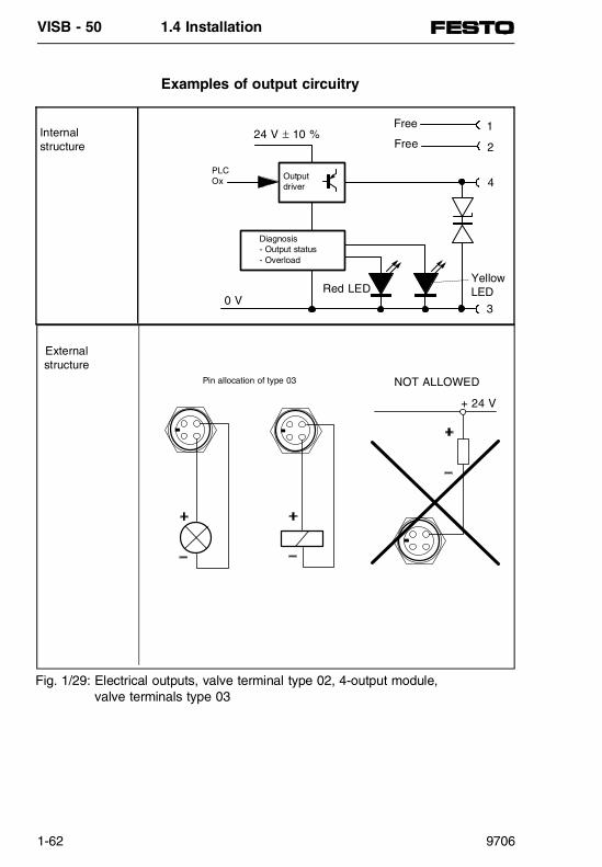
Examples of output circuitry
Internalstructure
External structure
Fig. 1/29: Electrical outputs, valve terminal type 02, 4-output module, valve terminals type 03
Output driver
Red LED
Diagnosis- Output status- Overload
1
2
4
3
24 V ± 10 %
PLCOx
0 V
Yellow LED
Free
Free
Pin allocation of type 03 NOT ALLOWED
+ 24 V
VISB - 50 1.4 Installation
1-62 9706

DUO cable
The DUO cable offers a simple connection for sen-sors with assignments for two inputs. The plugs onthe sensor side are intended for M8. There are threedifferent pairs of plug design.
C
AB
M12 x 1
Can be screwed intovalve terminal with sockets
Extension cable2.5 m5.0 m
Fastening by means of clamping strap
Fastening by means of screw
Identification plate
Socket
Plug
0.6 m
0.5 m
Duo cable
Y-distributor
Fig. 1/30: DUO cable and extension cable for simple connection of sensors
VISB - 50 1.4 Installation
9706 1-63
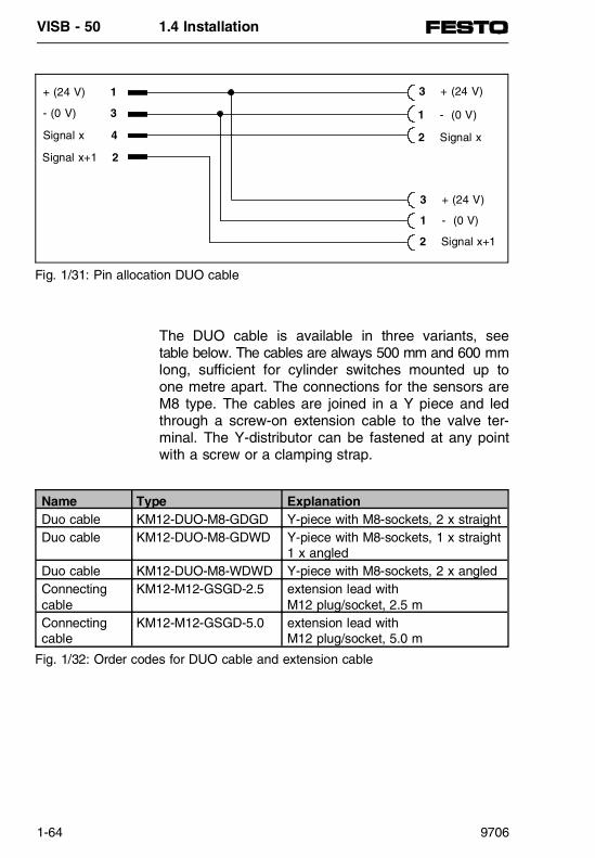
The DUO cable is available in three variants, seetable below. The cables are always 500 mm and 600 mmlong, sufficient for cylinder switches mounted up toone metre apart. The connections for the sensors areM8 type. The cables are joined in a Y piece and ledthrough a screw-on extension cable to the valve ter-minal. The Y-distributor can be fastened at any pointwith a screw or a clamping strap.
+ (24 V) 1
- (0 V) 3
Signal x 4
Signal x+1 2
3 + (24 V)
1 - (0 V)
2 Signal x
3 + (24 V)
1 - (0 V)
2 Signal x+1
Fig. 1/31: Pin allocation DUO cable
Name Type ExplanationDuo cable KM12-DUO-M8-GDGD Y-piece with M8-sockets, 2 x straightDuo cable KM12-DUO-M8-GDWD Y-piece with M8-sockets, 1 x straight
1 x angledDuo cable KM12-DUO-M8-WDWD Y-piece with M8-sockets, 2 x angledConnecting cable
KM12-M12-GSGD-2.5 extension lead with M12 plug/socket, 2.5 m
Connecting cable
KM12-M12-GSGD-5.0 extension lead with M12 plug/socket, 5.0 m
Fig. 1/32: Order codes for DUO cable and extension cable
VISB - 50 1.4 Installation
1-64 9706

Designation of inputs and outputs
For better monitoring during commissioning and formaintenance work the inputs and outputs should begiven designations which will ensure clear identifica-tion in the circuit diagram or in the program.
Valve terminal type 02
Valve terminal type 03
Fig. 1/33: Holder for identification plate of I/O connections
158968 (10 pieces)
18182 (20 piecesper frame)
Fig. 1/34: Holder for identification plate of electrical inputsand outputs
18182(20 pieces per frame)
18576 (64 piecesper frame)
18183 (5 units in bag)
VISB - 50 1.4 Installation
9706 1-65

Field bus connector assembly FBS-SUB-9-GS-9, PNo. 18529
1. Seal (7): insert in lower cover (9)and upper cover (6).
2. PCB (8): insert into the guide of thelower cover (9).Fix the PCB with countersunk screw (10) to the lowercover.
3. Screw the lower part of the PGcompression glands (5) in the uppercover (6) to the limit stop. Thread cable through the union nut (1),clamping ring (2) and cone seal (3).
4. Feed the cable through the uppercover.
5. Remove the insulation from the buscable as shown in figure 1/32 andconnect to the terminal block.
6. Push upper cover (6) over the PCBand connect with the lower cover.Screw the cone seal, clamping ringand union nut to the lower part of
the PG threaded connector.
7. Insert screws (4) in the connector housing to the limit stop and thenscrew in under pressure with a screwdriver until they protrude fromthe lower cover by 1...2 mm.
PLEASE NOTEOnly use the cable that is permittedfor the PROFIBUS-DP.
Fig. 1/35: Individual componentsof the plug
Sealing plug
Fig. 1/36: Close plug
VISB - 50 1.4 Installation
1-66 9706

WARNING- The terminating resistors must be switched on at
the segment start and segment end, (Fig.1/39).
- The terminating resistors must not be switched onwith looped-through bus cable, (Fig. 1/38).
- The cable ends at the segment start and the seg-ment end must be sealed with the sealing plug supplied, (Fig. 1/36).
A B
105
6
The braided screen mustbe fastened on directly
under the cable clamps
Fig. 1/37: Preparing the cable
Bus cable connector with "loopedthrough" bus cable, switch position OFF (terminating resistor is not switched on).
A B A B
Fig. 1/38: Terminating resistor OFF
Bus cable connector at segment start and segment end, switch position ON (terminating resistor is switched on).
A B
Fig. 1/39: Terminating resistor ON
VISB - 50 1.4 Installation
9706 1-67

Connection instructions for valve terminals
FESTO valve terminals with field bus nodes for thePROFIBUS-DP (FB9) can be advantageously used asa Slave in a system where a valve terminal with con-trol block SF 50 is the Master station. The field busnodes FB9 have a 4-pin rounded connector for theconnection to the field bus.
Connect the Slave station to the Master station asshown below.
AB
Master station Meaning Slave station
Connection A Data line A Pin 3 (S-)Connection B Data line B Pin 1 (S+)Braided screen Screening Pin 4
Fig. 1/40: SF 50 connection with FB9
VISB - 50 1.4 Installation
1-68 9706

Connector assembly S-SUB-15-GS-9, PNo. 18574, 18578
1. Seal (7): insert in lower cover (9)and upper cover (6)
2. Screw the lower part of the PG compression glands (5) in the uppercover (6) to the limit stop. Close unassigned cable ends with sealing plug (8).
3. Thread cable through the union nut (1),clamping ring (2) and cone seal (3).
4. Feed the cable through the uppercover.
5. Fasten the sub-D connector (11) tothe lower cover (9) with counter-sunk screws (10).
6. Remove a part of the insulationfrom the cable. Fit individual strandswith crimp contacts and contactpins according to the contact allocations into the sub-D connectoror remove a part of the insulationfrom the cable. Solder individualstrands according the contact alloca-tions into the sub-D-connector
7. Connect upper cover (6) with thelower cover. Screw the cone seal, clamping ring and union nut to thelower part of the PG threaded con-nector.
8. Insert screws (4) in the connector housing to the limit stop and thenscrew in under pressure with a screwdriver until they protrude fromthe lower cover by 1...2 mm.
2 models:- Solder connection- Crimp connection
Fig. 1/41: Components of the plug
VISB - 50 1.4 Installation
9706 1-69

Contact allocations on the 15-pin sub-D connector arevalid for all SB / SF 50 variants:
An additional clamping ring is included in the kit (item2 in Fig. 1/41).
This can be used with cables of different externaldiameters.
- without additional clamping ring 6.0...9.0 mm- with additional clamping ring 4.5...6.0 mm.
Contact number Contact description1 Screening2 TTY IN- (grey-blue)6 TTY OUT+ (brown)7 TTY OUT- (yellow)8 Screening9 TTY IN+ (white)
Fig. 1/42: Contact allocations for SB/SF 50
View in direction of arrow
VISB - 50 1.4 Installation
1-70 9706

Connector accessories
Designation Type nameStraight mains socket, PG 9 (for 1.5 mm2)
NTSD-GD-9
Straight mains socket, PG 13.5 (for 2.5 mm2)
NTSD-GD-9
Angled mains socket, PG 9 (for 1.5 mm2)
NTSD-GD-9
Sensor connector SEA-GS-7
Field bus connector for SINEC L2-DP (9-pin),
FBS-SUB-9-GS-9
Connection of L1 / B&B (15-pin),
with crimp connectionwith solder connection
S-SUB-15-GS-9S-SUB-15-GS-9-L
Cover plate for sub-D-connection(complies with IP 65, whenconnector is not inserted)
AK-SUB-9,15
VISB - 50 1.4 Installation
9706 1-71

VISB - 50 1.4 Installation
1-72 9706

Programmable valve terminalswith
control block SB 50 / SF 50
Part 2b: Valve terminal type 03
SIEMENS
RUN
STO P
BF
24VDC FUSE
L2-DP
PG
PN
350
655

PN 350 655 is included in: Manual 161123

Chapter summary
This manual consists of various parts which can beput together depending on the equipment fitted on thevalve terminal.
Part 1 Basic principles of installationcontains information which is not dependent on thetype of valve terminal or on the node selected.
Part 2a Valve terminal type 02System description of valve terminal type 02,contains all information specifically for this type ofterminal.
Part 2b Valve terminal type 03System description of valve terminal type 03,contains all information specifically for this type ofterminal.
Part 3 System description of the SB 50contains all PLC-specific information that isindependent of the valve terminal type.
Part 4 System description for SF 50 as Mastercontains additional information that is required whenusing the PROFIBUS-DP.
Part 5 System description for SF 50 as DP Slavecontains additional information that is required whenusing the SF 50/DP Slave (SL 50).
Part 6 Appendixcontains additional information concerning commandsets, abbreviations, accessories, literature, etc.
PN
350
655
VISB - 50
9706 2b-I

Notes
___________________________________________
___________________________________________
___________________________________________
___________________________________________
___________________________________________
___________________________________________
___________________________________________
___________________________________________
___________________________________________
___________________________________________
___________________________________________
___________________________________________
___________________________________________
___________________________________________
___________________________________________
___________________________________________
___________________________________________
___________________________________________
___________________________________________
___________________________________________
___________________________________________
___________________________________________
VISB - 50
2b-II 9706
TABLE OF CONTENTS
2.1 COMPONENTSStructure of the valve terminal (type 03) ...........2b-3Function summary .............................................2b-6Valves ................................................................2b-8
2.2 FITTINGFitting the components ....................................2b-11Input/output modules .......................................2b-12End plates ........................................................2b-14Top-hat rail clamping unit ................................2b-16Fitting the valve terminal..................................2b-17Wall fitting ........................................................2b-17Top-hat rail fitting.............................................2b-18
2.3 ELECTRICAL CONNECTIONSOperating voltage.............................................2b-23Calculating the current consumption ...............2b-24Operating voltage connection..........................2b-25Protective earthing...........................................2b-27Connecting the input modules.........................2b-29Connecting the output modules.......................2b-31
2.4 ADDRESSINGGeneral ............................................................2b-37Calculating the configuration data ...................2b-37Calculating the number of inputs/outputs ........2b-38Address assignment of the valve terminal ......2b-39Basic rules .......................................................2b-40Address assignment after extension ............... 2b-43Diagnostics information in IB7......................... 2b-45
2.5 TECHNICAL SPECIFICATIONS
PN
350
655
VISB - 50-03 Table of contents
9706 2b-III

VISB - 50-03 Table of contents
2b-IV 9706
2.1 COMPONENTS
VISB - 50-03 2.1 Components
9706 2b-1

Contents
2.1 COMPONENTSStructure of valve terminal type 03 ...................2b-3Function summary .............................................2b-6Valves ................................................................2b-8
VISB - 50-03 2.1 Components
2b-2 9706

2.1 COMPONENTS
Structure of valve terminal type 03
Valve terminal type 03 consists of individual modules.Each of the different modules is assigned with diffe-rent functions and connecting, display and operatingelements. This is summarized in the diagram below.
Figure Module
1 Node with control block SB 50 or SF 50
2 Electronic modules (input/output modules), fitted with• Digital inputs (modules with 4 or 8 inputs)• Digital outputs (modules with 4 outputs)
3 End plate left, with hole for additional PE connection
4 Pneumatic modules, valves• Two valve sizes, 4.0 mm / 7.0 mm (MIDI / MAXI)• Solenoid valves• Double solenoid valves • Mid-position valves• Blanking plates
5 Pneumatic modules for additional air supply
6 End plate right• With and without connections• With and without regulator for limiting pilot pressure
Fig. 2/1: Modules of valve terminal type 03
SIEMENS
3 2 1 4 5 4 6
VISB - 50-03 2.1 Components
9706 2b-3

The following connecting, display and operating ele-ments are to be found on the electronic modules:
Fig. 2/2: Operating, display and connecting elements of the electronicmodules
1 End plate left, additional PE connection2 Input socket for two electrical inputs3 Two green LEDs (one LED per input)4 Input socket for one electrical input5 Green LED (per input)6 Output socket for electrical output7 Yellow LED (status display per output)8 Red LED (error display per output)9 Control block with LEDs and diagnostic interface
10 End plate right, for connecting electrical comps.11 Operating voltage connection12 Fuse for inputs and sensors
SIEMENS
1 2 3 4 5 6 7 8 9 10
11 12
VISB - 50-03 2.1 Components
2b-4 9706

The following connecting, display and operating ele-ments are to be found on the pneumatic modules:
Fig. 2/3: Display and connecting elements of the pneumatic modules
1 End plate left, additional PE connection2 Control block with LEDs and diagnostic interface3a Yellow LED upper valve solenoid coil on MIDI valve (side 14)3b Yellow LED lower valve solenoid coil on MIDI valve (side 12)3c Yellow LED right-hand valve solenoid coil on MAXI valve (side 14)3d Yellow LED left-hand valve solenoid coil on MAXI valve (side 12)4a Manual override upper valve solenoid coil MIDI valve4b Manual override lower valve solenoid coil MIDI valve4c Manual override MAXI valve5a Valve location inscription field MIDI valve5b Valve location inscription field MAXI valves6 Adapter plate MIDI/MAXI with regulator for control pressure7 End plate right with common tubing connections8 Working connections 2 and 4 per valve9 Additional air supply10 Regulator for limiting pilot pressure to 5 bar
SIEMENS
1 2 3a 3a 6 3d 3c 4c 7
9 3b 10 8
4a
4b8 5b
5a
VISB - 50-03 2.1 Components
9706 2b-5

Function summary
The heart of the programmable valve terminal is thecontrol block SB 50-03. This contains a PLC and theelectronic components required for controlling a valveterminal independently. In this way the user can solvehis automation tasks on site independently.
The user programs for the programmable valve termi-nal are created on a programmer or a PC with the aidof the programming software STEP5. The programm-ing languages CSF, LDR and STL can be used. Theprograms are loaded into the programmable valve ter-minal via the diagnostic interface.
Programmer or PC
Digitalinputs
Digitaloutput
Sensors
Actuator
2 4
1Pressure supply
Input/output modules Node Pneumatic modules
Fig. 2/4: Function summary of programmable valve terminal type 03
VISB - 50-03 2.1 Components
2b-6 9706

The pneumatic modules create the following connec-tions:• common galleries for air supply and exhaust• electrical signals from all solenoid valve coils
Working connections 2 and 4 are supplied for eachvalve location on the individual pneumatic modules.
By means of the common galleries on the pneumaticend plate, the valves are supplied with compressedair, and both the exhaust air and pilot air from thevalves are vented. Modules for air supply are alsoavailable, in order that different working pressures canbe used.
Further information on their use is to be found in thepneumatics section of your valve terminal manual.Only the electronic modules and the control block aredescribed here.
The input modules process input signals (e.g. fromsensors) and transmit these signals to the internalcontroller.The output modules are universal electrical outputsand control low-current consuming devices with posi-tive logic, e.g. further valves, lamps, etc..
VISB - 50-03 2.1 Components
9706 2b-7

Valves
The following types of valves are available for control-ling the cylinders. They are fitted onto the baseplates. Exact details are given in the pneumatics sec-tion of the manual for valve terminals type 03.
Two valve sizes are available. These sizes can befitted together on the terminal.
Function circuit Type designation NameMIDI:MEH-5/2-4,0-S-VIMAXI:MTH-5/2-7,0-L-S-VI
Single solenoid valve, 5-way with spring reset,separate pilot air supply
MIDI:JMEH-5/2-4,0-S-VIMAXI:JMTH-5/2-7,0-S-VI
Double solenoid valveseparate pilot air supply
MIDI:MEH-5/3B-4,0-S-VIMAXI:MTH-5/3B-7,0-S-VI
Mid-position valve,both sides pressurizedin mid-position,separate pilot air supply
MIDI:MEH-5/3E-4,0-S-VIMAXI:MTH-5/3E-7,0-S-VI
Mid-position valve,both sides exhaustedin mid-position,separate pilot air supply
MIDI:MEH-5/3G-4,0-S-VIMAXI:MTH-5/3G-7,0-S-VI
Mid-position valve,both sides blockedin mid-position,separate pilot air supply
Fig. 2/5: Valves for use on valve terminal type 03
VISB - 50-03 2.1 Components
2b-8 9706

2.2 FITTING
VISB - 50-03 2.2 Fitting
9706 2b-9

Contents
2.2 FITTINGFitting the components ....................................2b-11Input/output modules .......................................2b-12End plates........................................................2b-14Top-hat rail clamping unit ................................2b-16Fitting the valve terminal .................................2b-17Wall fitting ........................................................2b-17Top-hat rail fitting.............................................2b-18
VISB - 50-03 2.2 Fitting
2b-10 9706

2.2 FITTING
FITTING THE COMPONENTS
You thereby avoid:• Uncontrolled movements of loose tubing• Undesired movements of the connected actuators• Undefined switching states of the electronic compo-
nents
You thereby avoid damaging the valve terminal com-ponents.
WARNING
• Switch off the following before undertakinginstallation and maintenance work:
• the compressed air supply
• the operating voltage supply for the electronic components (pin 1 of oper. voltage connection)
• Operating voltage supply for the outputs/valves(pin 2 of operating voltage connection)
CAUTION
• The components of the valve terminal containelectrostatically vulnerable parts.
• Do not therefore touch any contact surfacesof the plug connectors on the sides of thecomponents.
• Observe the regulations for dealing withelectrostatically vulnerable components.
VISB - 50-03 2.2 Fitting
9706 2b-11

Input/output modules
Before the valve terminal can be extended or con-verted, it must be dismantled.
Dismantling (see also following diagram)• Remove completely the screws of the relevant
modules. The modules are now held together onlyby the plug connectors.
• Pull the modules carefully and without tippingaway from the plug connectors.
• Replace broken or damaged seals.
PLEASE NOTETreat all the modules and components of thevalve terminal with the utmost care.Pay special attention to the following:
• Screw connectors must not be subjected tomechanical stress.
• The screws must fit exactly (otherwise thethreads will be damaged).
• The specified torques must be observed.The modules must not be offset (IP 65).
• Connecting surfaces must be clean (avoidleakage and incorrect contacts).
• The contacts of the valve solenoid coils must notbe bent (they cannot be bent back, i.e. they willbreak off if bent back).
With subsequently ordered modules and compo-nents, observe also the fitting instructions in theproduct packing.
VISB - 50-03 2.2 Fitting
2b-12 9706

Fitting (see also following diagram):
Fit the modules as follows:• Fit a (new) seal on the right-hand contact surface
facing the node.• Fit the module as shown below.
PLEASE NOTE
• Place subsequently ordered modules wherepossible after the last module before the endplate.
• Do not fit more than 12 electronic modules.Observe also the addressing limits of controlblock SB 50-03
Seal
Tightening torque offastening screwsmax. 1 Nm
Fig. 2/6: Fitting the electronic modules (I/O modules)
VISB - 50-03 2.2 Fitting
9706 2b-13
End plates
A left-hand and a right-hand end plate are required asa mechanical termination of the valve terminal. Theseend plates fulfil the following functions:• They comply with protection class IP 65.• They contain connections and contacts for the
protective earthing.• They contain holes for wall mounting and for the
top-hat rail clamping unit.
There are three types of right-hand end plate:• MIDI:
with common tubing connections for the com-pressed air supply for the pneumatic modules andintegrated regulator for the auxiliary pilot air (5 bar)
• MIDI / MAXI:with common tubing connections for the com-pressed air supply for the pneumatic modules without integrated regulator
• MAXI:without common tubing connections
CAUTIONThe right-hand end plate must be earthed before itis fitted. This is to avoid high voltages on the metalsurfaces in the case of a fault.
VISB - 50-03 2.2 Fitting
2b-14 9706

Earth the end plates as follows:• Right-hand end plate:
In order to earth the right-hand end plate, connectthe cable fitted on the inside to the appropriate con-tacts on the pneumatic modules (see diagram be-low).
• Left-hand end plate:The left-hand end plate is connected conductivelyto the other components via spring contacts whichare already fitted.
RemarkInstructions on earthing the complete valve terminalare to be found in the chapter "Installation".
The diagram below shows how the end plates arefitted.
Tightening torque of fastening screwsmax. 1 Nm
Seal
Seal
Ready-fittedearth cable
Contact for earth cable
Fig. 2/7: Fitting the end plates
VISB - 50-03 2.2 Fitting
9706 2b-15

Top-hat rail clamping unit
The top-hat rail clamping unit is required if the termi-nal is to be fitted onto a top-hat rail (support rail asper EN 50022). The hat rail clamping unit is fastenedto the rear of the end plates as shown below.
Before fitting ensure that:• the surfaces to be glued are clean
(cleaned with spirit).
After fitting ensure that:• the flat-head screws are tightened (6).• the levers are secured with locking screws (7).
Fig. 2/8: Fitting the top-hat rail clamping unit
1 Adhesive rubber foot2 Clamping element3 Left-hand lever4 Right-hand lever5 O-ring6 Flat-head screw7 Locking screw
VISB - 50-03 2.2 Fitting
2b-16 9706

FITTING THE VALVE TERMINAL
Wall fitting
Proceed as follows:• Calculate the weight of the terminal
(weigh or estimate),General rule: 800 g per pneumatic module, 1000 g for node,400 g per electronic module.
• Make sure that the fastening surface can supportthis weight.
• Fasten the terminal with four M6 screws as shownbelow (fitting position as desired). Use spacers ifnecessary.
M6 M6
Fig. 2/9: Wall fitting of valve terminal
VISB - 50-03 2.2 Fitting
9706 2b-17

Top hat rail fitting
The valve terminal is suitable for fitting onto a top-hatrail (support rail as per EN 50022). For this purposethere is a guide groove on the rear of each modulefor hanging the terminal on the hat rail.
CAUTION
• Fasten the valve terminal onto the top-hat railwith the top-hat rail clamping unit.
• If the terminal is fitted in a sloping position or issubjected to vibration, fasten the clamping unitwith a screw to protect it against unintentionalloosening or opening.
PLEASE NOTE
• If the terminal is fitted in a horizontal positionand is not subjected to vibration, the fasteningof the top-hat rail clamping unit is sufficient.
• If your terminal does not have a top-hat railclamping unit, this can be ordered and fitted at alater stage.
VISB - 50-03 2.2 Fitting
2b-18 9706

Proceed as follows:• Calculate the weight of the terminal
(weigh or estimate).General rule: 800 g per pneumatic module, 1000 g for node, 400 g per electronic module.
• Make sure that the fastening surface can supportthis weight.
• Fit a top-hat rail (support rail as per EN 50022 -35x15; width 35 mm, height 15 mm).
• Fasten the top-hat rail to the fastening surface atleast every 100 mm.
• If the top-hat rail clamping unit is fitted at the fac-tory, the clamping unit must be unlocked.
• Hang the terminal onto the top-hat rail. Use the top-hat rail clamping unit to secure the terminal onboth sides against tilting or slipping (see followingdiagram).
• If the terminal is fitted in a sloping position or at apoint subjected to vibration, protect the top-hat railclamping unit with two screws (7) against uninten-tional loosening/opening.
VISB - 50-03 2.2 Fitting
9706 2b-19

Top-hat rail clamping unit locked
Locking screw
Top-hat rail clamping unitopen (unlocked)
Valve terminaltype 03
Fig. 2/10: Fitting the valve terminal on a top-hat rail
VISB - 50-03 2.2 Fitting
2b-20 9706

2.3 ELECTRICAL CONNECTIONS
PN
350
655
VISB - 50-03 2.3 Electrical connections
9706 2b-21

Contents
2.3 ELECTRICAL CONNECTIONSOperating voltage ............................................2b-23Calculating the current consumption ...............2b-24Operating voltage connection..........................2b-25Protective earthing...........................................2b-27Connecting the input modules.........................2b-29Connecting the output modules.......................2b-31Short circuit/overload .......................................2b-33
v:\sb50-gb\typ-03\t03-k23.chpv:\sb50-gb\typ-03\t03-k23.chp
VISB - 50-03 2.3 Electrical connections
2b-22 9706

2.3 ELECTRICAL CONNECTIONS
Operating voltage
WARNINGAn isolating transformer as per DIN/VDE 0551 withat least 4 kV isolation resistance is required in or-der that the operating voltages can be separated asper VDE 0113.
CAUTIONThe power supply to the outputs/valves (Pin 2)must be fused externally with max. 10 A. The exter-nal fuse prevents damage to the valve terminalfunctions in the event of a short circuit.
Please observe the following before connecting theoperating voltages:• Calculate the complete current consumption ac-
cording to the following table and select both a suit-able power unit and cable cross section.
• Avoid long distances between the power unit andthe valve terminal. Calculate also the permitted dis-tance according to part 1 of this manual INSTALLA-TION. The following rule applies:
Power consumption
Cable cross section
Distance
Pin 1 = 2.2 APin 2 = 10 A max.VOp = 24 V
1.5 mm2 8 m
2.5 mm2 14 m
VISB - 50-03 2.3 Electrical connections
9706 2b-23

Calculating the current consumption
The following table shows the calculation of the totalcurrent consumption. The different consumption of theMIDI and MAXI valves must be taken into consider-ation. The values specified have been rounded up.
Current consumption of electronic compo-nents node and inputs (pin 1, 24 V ± 25 %)Node
Number of simultaneously assigned sensor inputs ____ x 0.010 A
Sensor supply (seemanufacturer specifications) ____ x _____ A
Current consumption of electronic compo-nents node and inputs max. 2.2 A
Current consumption of valves and outputs(pin 2, 24 V ± 10 %)Number of valve coils MIDI(simultaneously under power) ____ x 0.055 ANumber of valve coils MAXI(simultaneously under power) ____ x 0.095 ANumber of simultaneouslyactivated electr. outputs: ____ x 0.010 ALoading current of sim.activated electr. outputs: ____ x _____ A
Current cons. of outputsp (in 2) max. 10 A
Total current consumption of valve terminal typ 03
0.200 A
Σ A+
Σ A+
Σ A= Σ A
Σ A+
Σ A+
Σ A+
Σ A+
Σ A=
Σ A=
Σ A+
Fig. 2/11: Calculating the current consumption of the valve terminal
VISB - 50-03 2.3 Electrical connections
2b-24 9706

Operating voltage connection
The 24 V operating voltages are connected at thelower left-hand edge of the control block.
The following + 24 V DC supplies are made via thisconnection:
• The operating voltage for internal electronic compo-nents, PLC and the inputs of the input modules(pin 1:+ 24 V DC, tolerance ± 25 %).
• The operating voltage for the outputs of the valvesand the outputs of the output modules (pin 2:+ 24 V DC, tolerance ± 10 %, external fuse max.10 A required).
RecommendationConnect the operating voltage for the out-puts/valves via the EMERGENCY STOP circuit.
Operating voltage connection
Fuse for electroniccomponents andinputs
Fig. 2/12: Position of operating voltage connection
VISB - 50-03 2.3 Electrical connections
9706 2b-25

The following diagram shows the Pin assignment ofthe operating voltage connection.
PLEASE NOTEWith a common voltage supply for pin 1 (electroniccomponents and inputs) and pin 2 (outputs/valves),the lower tolerance of 10 % for both circuits mustbe observed.
Check the 24 V operating voltage of the outputs whilstthe system is in operation. Ensure that the operatingvoltage of the outputs lies within the permitted tole-rances even during full operation.
RecommendationUse a close-loop regulated power unit.
24 V supply forvalves/outputs
0 V
PE connection(incoming contact)
24 V supplyelectronic comps.and inputs
1
4 2
3
Fig. 2/13: Pin assignment of operating voltage connection
VISB - 50-03 2.3 Electrical connections
2b-26 9706

Protective earthing
The valve terminal has the following protective earthconnections:• on the operating voltage connection
(pin 4 incoming contact)• on the left-hand end plate (M4 thread).
Connection example
The following diagram shows the connection of acommon 24 V supply for pins 1 and 2. Please notethat:• the supply to the outputs/valves must be protected
against short circuit/overload with an external fusemax. 10 A
• the supply to the electronic components and inputsmust be protected against short circuit/overloadwith an external fuse 3.15 A
• the common tolerance of 24 V DC ± 10 % must beobserved
• equalizing currents must be avoided when the twoearth cables are connected, e.g. by means of ca-bles with appropriate cross section as a potentialcompensation.
PLEASE NOTE
• Always connect the protective earth conductorto pin 4 of the operating voltage connection.
• The protective earth connection on the left-hand end plate can also be used. In this case make sure that both protectiveearth conductors have the same potential andthat there are no equalizing currents.
VISB - 50-03 2.3 Electrical connections
9706 2b-27

3 1 2 4
3.15 A
10 A
External fuses
EMERGENCY STOP
PE connection pin 4 designed for 12 A
Connecting cable for potential compensationof earth connections
AC 230 V
DC 24 V± 10 %
Fig. 2/14: Connecting a common 24 V supply and both PE conductors
VISB - 50-03 2.3 Electrical connections
2b-28 9706

CONNECTING THE INPUT MODULES (PNP/NPN)
You thereby avoid:• Uncontrolled movements of loose tubing• Undesired movements of the connected actuators• Undefined switching states of the electronic compo-
nents
WARNINGSwitch off the following before undertaking installa-tion or maintenance work:
• The compressed air supply
• The operating voltage supply for the electroniccomponents (pin 1)
• The operating voltage supply for the outputs/valves (pin 2).
Input module (4 inputs) Input module (8 inputs)
Fig. 2/15: Digital input modules 4/8 inputs (example PNP)
Socketseach withone digitalinput
GreenLED
Socketseach withtwo digitalinpüuts
OnegreenLEDper digitalinput
Connection preferably with DUO cable
VISB - 50-03 2.3 Electrical connections
9706 2b-29

Modules are available for user applications with fouror eight inputs. The inputs have positive logic (PNPinputs).
Pin assignment
The following diagram shows the Pin assignment ofall the PNP/NPN inputs on a module.
Pin assignment (4 inputs) Pin assignment (8 inputs)
0 0
1
1 2
3
2 4
5
3 6
7
Fig. 2/16: Pin assignment on the input modules
1 4
32
0 Vfree
+ 24 V InputIx
1 4
32
0 VInputIx+1
+ 24 V InputIx
1 4
32
0 Vfree
+ 24 V InputIx+1
1 4
32
0 VInputIx+3
+ 24 VInputIx+2
1 4
32
0 Vfree
+ 24 VInputIx+2
1 4
32
0 VInputIx+5
+ 24 VInputIx+4
1 4
32
0 Vfree
+ 24 VInputIx+3
1 4
32
0 VInputIx+7
+ 24 V InputIx+6
VISB - 50-03 2.3 Electrical connections
2b-30 9706

CONNECTING THE OUTPUT MODULES (PNP)
You thereby avoid: • Uncontrolled movements of loose tubing• Undesired movements of the connected actuators• Undefined switching states of the electronic compo-
nents
WARNINGSwitch off the following before undertaking installa-tion or maintenance work:
• The compressed air supply
• The operating voltage supply for the electroniccomponents (pin 1)
• The operating voltage supply for the outputs/valves (pin 2)
Output module (4 outputs)
Fig. 2/17: Digital 4-output module
0
1
2
3
Yellow LED peroutput (status)
Red LED per output (short circuit)
Socketseach with onedigitaloutput
VISB - 50-03 2.3 Electrical connections
9706 2b-31

Four transistor outputs are available for user applica-tions on the output modules of the valve terminal. Theoutputs have positive logic (PNP outputs).
Pin assignment
The following diagram shows the pin assignment of allthe outputs on a module.
Pin assignment (4 outputs)
0
1
2
3
Fig. 2/18: Pin assignment on output modules (4 outputs)
1 4
32
0 Vfree
freeOutput
Qx
1 4
32
0 Vfree
freeOutputQx+1
1 4
32
0 Vfree
freeOutputQx+2
1 4
32
0 Vfree
freeOutputQx+3
VISB - 50-03 2.3 Electrical connections
2b-32 9706

Short circuit / overload
The electrical output modules of the valve terminalstype 03 are short circuit protected. Monitoring is madeon a thermal basis. If there is an overload, the outputwill be switched off and the red LED will light up.
This status is main-tained until the rele-vant output is reset,there is not thereforeany pulsing of theoutput which maystill be short cir-
cuited. When the output is reset and then set again,the user can ascertain whether there is still a shortcircuit.
- Maximum output current 0.5 A per output- Triggering current max. 1.5 A- Response time max. 1 sec- No galvanic isolation
A maximum light output of 10 W is permitted on account of the PTC characteristics of bulbs.
Yellow LED peroutput (status)
Red LED per output (short circuit)
VISB - 50-03 2.3 Electrical connections
9706 2b-33

Notes
___________________________________________
___________________________________________
___________________________________________
___________________________________________
___________________________________________
___________________________________________
___________________________________________
___________________________________________
___________________________________________
___________________________________________
___________________________________________
___________________________________________
___________________________________________
___________________________________________
___________________________________________
___________________________________________
___________________________________________
___________________________________________
___________________________________________
___________________________________________
___________________________________________
___________________________________________
VISB - 50-03 2.3 Electrical connections
2b-34 9706

2.4 ADDRESSING
PN
350
655
VISB - 50-03 2.4 Addressing
9706 2b-35

Contents
2.4 ADDRESSINGGeneral ............................................................2b-37Calculating the configuration data ...................2b-37Calculating the number of inputs/outputs........2b-38Address allocation of the valve terminal .........2b-39Basic rules .......................................................2b-40Address allocation after extension ..................2b-43Diagnostics information in IB7.........................2b-45
VISB - 50-03 2.4 Addressing
2b-36 9706
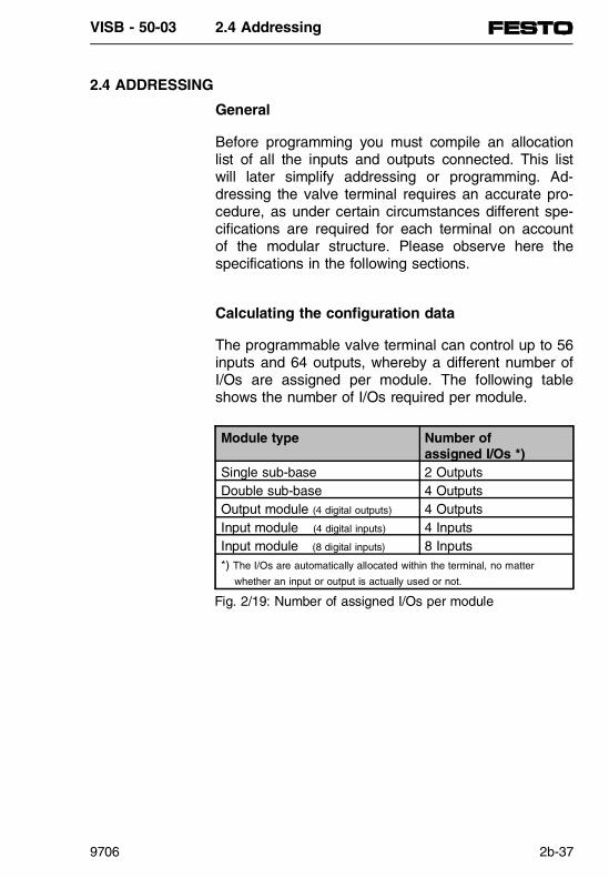
2.4 ADDRESSING
General
Before programming you must compile an allocationlist of all the inputs and outputs connected. This listwill later simplify addressing or programming. Ad-dressing the valve terminal requires an accurate pro-cedure, as under certain circumstances different spe-cifications are required for each terminal on accountof the modular structure. Please observe here thespecifications in the following sections.
Calculating the configuration data
The programmable valve terminal can control up to 56inputs and 64 outputs, whereby a different number ofI/Os are assigned per module. The following tableshows the number of I/Os required per module.
Module type Number of assigned I/Os *)
Single sub-base 2 OutputsDouble sub-base 4 OutputsOutput module (4 digital outputs) 4 OutputsInput module (4 digital inputs) 4 InputsInput module (8 digital inputs) 8 Inputs*) The I/Os are automatically allocated within the terminal, no matter
whether an input or output is actually used or not.
Fig. 2/19: Number of assigned I/Os per module
VISB - 50-03 2.4 Addressing
9706 2b-37
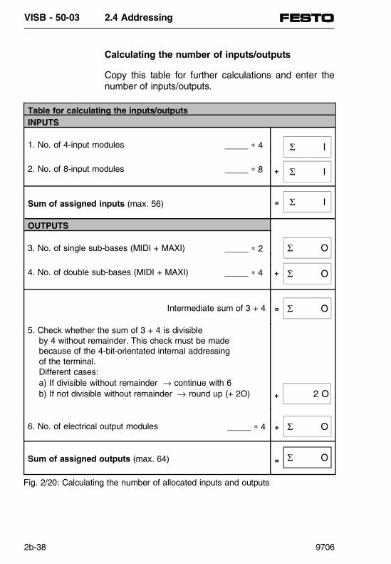
Calculating the number of inputs/outputs
Copy this table for further calculations and enter thenumber of inputs/outputs.
Table for calculating the inputs/outputsINPUTS
1. No. of 4-input modules _____ ∗ 4
2. No. of 8-input modules _____ ∗ 8
Sum of assigned inputs (max. 56)
OUTPUTS
3. No. of single sub-bases (MIDI + MAXI) _____ ∗ 2
4. No. of double sub-bases (MIDI + MAXI) _____ ∗ 4
Intermediate sum of 3 + 4
5. Check whether the sum of 3 + 4 is divisible by 4 without remainder. This check must be made because of the 4-bit-orientated internal addressing of the terminal. Different cases: a) If divisible without remainder → continue with 6 b) If not divisible without remainder → round up (+ 2O)
6. No. of electrical output modules _____ ∗ 4
Sum of assigned outputs (max. 64)
+
=
=
+
+
+
=
Σ O
Σ O
2 O
Σ O
Σ O
Σ O
Σ I
Σ I
Σ I
Fig. 2/20: Calculating the number of allocated inputs and outputs
VISB - 50-03 2.4 Addressing
2b-38 9706

Address allocation of the valve terminal
The address allocation of the outputs of a modularvalve terminal depends on the equipment fitted on theterminal. A distinction is made between the followingequipment fitted:
• Valves and digital I/O modules• Valves only• Digital I/O modules only
The following basic rules apply to the address alloca-tion of terminals fitted with these variations of equip-ment.
PLEASE NOTEFor your assistance there is a Festo softwarepackage which (depending on the fitting) calculatesand prints out the addresses of a terminal. Ask yourFesto technical advisor.
PLEASE NOTEIf two addresses are occupied for one valve location, the following assignment applies:lower-value address → pilot solenoid 14 higher-value address → pilot solenoid 12
VISB - 50-03 2.4 Addressing
9706 2b-39

Basic rule 1
The mixed fitting takes into consideration the:• Valves• Digital I/O modules
1. OutputsThe address allocation of the outputs does not depend on the inputs.
1.1 Address allocation of the valves:• Addresses should be assigned in ascending order without gaps• Counting begins on the node from left to right • Single sub-bases always occupy 2 addresses• Double sub-bases always occupy 4 addresses• Maximum 26 valve solenoid coils can be
addressed.
1.2 Rounding up to 4 bits: different cases:a) If the number of addresses can be divided evenly by 4, continue with section 1.3. b) If the number of addresses cannot be divided
evenly by 4, the number must be rounded up to 4 because of the 4-bit orientated addressing. The rounded 2 bits in the address range
cannot be used.
1.3 Address allocation of the output modules:After the (rounded 4-bit) addressing ofthe valves, the digital outputs are addressed.• Addresses should be allocated in ascending order without gaps• Counting begins on the node from right to left.• Counting on the individual modules is from top to bottom.• Digital output modules always occupy 4 addresses.
VISB - 50-03 2.4 Addressing
2b-40 9706

2. InputsThe address allocation of the inputs does not depend on the outputs.
2.1 Address allocation of the input modules:• Addresses should be assigned in ascending. order without gaps.• Counting begins on the node from right to left • Counting on the individual modules is from top to bottom.• 4-input modules always occupy 4 addresses.• 8-input modules always occupy 8 addresses.
Basic rule 2
If only valves are used, the address allocation is al-ways as described in basic rule 1.
Basic rule 3
If only electrical I/Os are used, the address allocationis always as described in basic rule 1.
PLEASE NOTE
• Maximum 26 valve solenoid coils can beaddressed.
• The last two positions on the valve side neednot be rounded up.
PLEASE NOTE
• Counting of the addresses begins immediatelyto the left of the node.
• The last two positions on the valve side neednot be rounded up.
• Maximum 64 digital outputs and 56 inputs canbe addressed.
VISB - 50-03 2.4 Addressing
9706 2b-41
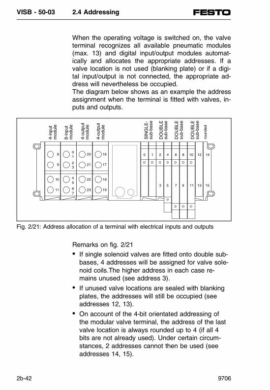
When the operating voltage is switched on, the valveterminal recognizes all available pneumatic modules(max. 13) and digital input/output modules automat-ically and allocates the appropriate addresses. If avalve location is not used (blanking plate) or if a digi-tal input/output is not connected, the appropriate ad-dress will nevertheless be occupied.The diagram below shows as an example the addressassignment when the terminal is fitted with valves, in-puts and outputs.
Remarks on fig. 2/21• If single solenoid valves are fitted onto double sub-
bases, 4 addresses will be assigned for valve sole-noid coils.The higher address in each case re-mains unused (see address 3).
• If unused valve locations are sealed with blankingplates, the addresses will still be occupied (see addresses 12, 13).
• On account of the 4-bit orientated addressing ofthe modular valve terminal, the address of the lastvalve location is always rounded up to 4 (if all 4bits are not already used). Under certain circum-stances, 2 addresses cannot then be used (see addresses 14, 15).
0 1 2
3
4
5
6
7
8
9
10
11
12
13
14
15
16
17
18
19
20
21
22
23
01
23
45
67
8
9
10
11
4-in
put
mod
ule
4-ou
tput
mod
ule
4-ou
tput
mod
ule
8-in
put
mod
ule
SIN
GLE
-su
b-ba
se
DO
UB
LEsu
b-ba
se
DO
UB
LEsu
b-ba
se
DO
UB
LEsu
b-ba
se
roun
ded
Fig. 2/21: Address allocation of a terminal with electrical inputs and outputs
VISB - 50-03 2.4 Addressing
2b-42 9706
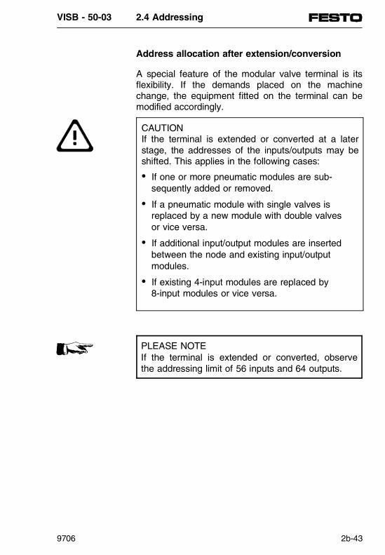
Address allocation after extension/conversion
A special feature of the modular valve terminal is itsflexibility. If the demands placed on the machinechange, the equipment fitted on the terminal can bemodified accordingly.
PLEASE NOTEIf the terminal is extended or converted, observethe addressing limit of 56 inputs and 64 outputs.
CAUTIONIf the terminal is extended or converted at a laterstage, the addresses of the inputs/outputs may beshifted. This applies in the following cases:
• If one or more pneumatic modules are sub-sequently added or removed.
• If a pneumatic module with single valves isreplaced by a new module with double valvesor vice versa.
• If additional input/output modules are insertedbetween the node and existing input/outputmodules.
• If existing 4-input modules are replaced by8-input modules or vice versa.
VISB - 50-03 2.4 Addressing
9706 2b-43

Using the standard fitting from the previous diagram,the following diagram shows the modifications to theaddresses when the terminal is extended.
Remarks on fig. 2/22Air supply modules and intermediate air supply modules do not occupy any addresses.
0 1 2
3
4
5
6
7
8
9
10
11
12
13
20
21
22
23
24
25
26
27
01
23
45
67
8
9
10
11
14
15
16
17
18 19
4-in
put
mod
ule
4-ou
tput
mod
ule
4-ou
tput
mod
ule
8-in
put
mod
ule
SIN
GLE
sub
-bas
e
DO
UB
LE s
ub-b
ase
DO
UB
LE s
ub-b
ase
DO
UB
LE s
ub-b
ase
DO
UB
LE s
ub-b
ase
SIN
GLE
sub
-bas
e
no r
ound
ing
air
supp
ly
Fig. 2/22: Address allocation of a valve terminal after extension/conversion
VISB - 50-03 2.4 Addressing
2b-44 9706

Diagnostics information in IB7 (Input Byte 7)
The valve coils, the electrical inputs of sensors andthe additional electrical outputs are addressed by thePLC program as on-board peripherals.
The address range of the inputs is theoretically fromI0.0 to I6.7. The diagnostics information is at the ad-dresses I7.0 to I7.7. If I7.2 is set by the operatingsystem, the short-circuited output can be located viaFB231.
For further details, see part 3.
Address Diagnostic informationI7.0 AS-iI7.1 AS-iI7.2 Short circuit outputsI7.3 AS-iI7.4 Voltage supply sensors VSEN < 10 VI7.5 Voltage supply valves VVAL < 21.6 VI7.6 Voltage supply valves VVAL < 10 VI7.7 Analogue: hardware error
Fig. 2/23: Diagnostic information in IB7
VISB - 50-03 2.4 Addressing
9706 2b-45

VISB - 50-03 2.4 Addressing
2b-46 9706

2.5 TECHNICAL SPECIFICATIONS
PN
350
655
VISB - 50-03 2.5 Technical specifications
9706 2b-47

Contents
2.5 TECHNICAL SPECIFICATIONSGeneral ............................................................2b-49Operating voltages...........................................2b-50Electrical input modules...................................2b-51Electrical output modules ................................2b-51Control block SB 50-03 / SF 50-03 .................2b-52Electromagnetic compatibility ..........................2b-52
VISB - 50-03 2.5 Technical specifications
2b-48 9706

2.5 TECHNICAL SPECIFICATIONS
General
Protection class (as per DIN 40050)
Temperature during•operation•storage/transport
Chemical resistance
IP 65
0 oC...+ 50 oC- 20 oC...+ 60 oC
See Festo PneumaticsCatalogue (Resistancetable)
Dimensions (width)NodeSub-baseValveAir supplyI/O module
72 mm36 mm18 mm36 mm36 mm
Oscillation(conforming to IEC 68,parts 2...6)
Frequency range 5...150 Hz5...8 Hz at 3.5 mm8...25 Hz at 1 g25...57 Hz at 0.35 mm57...150 Hz at 5 g
VISB - 50-03 2.5 Technical specifications
9706 2b-49

Operating voltage for electronic comps. and inputs
(Pin 1 – operatingvoltage connection)• Rated value (protected against
incorrect polarity)
24 V DC
• Tolerance ± 25 %(18 V...30 V DC)
• Residual ripple 4 Vpp• Current consumption (at 24 V)
200 mA + sum ofcurrent cons. of inputs
• Fusing of supply to inputs/sensors
Internal 2 A, slow-blowing
Power consumption (P)• Calculation P[W] = (0.2 A +
∑ I Inputs) × 24 V
Operating voltage for outputs and valves
(Pin 2 – operating voltageconnection)
External fuse required
• Rated value (protected against incorrect polarity)
24 V DC, max. 10 A
• Tolerance ± 10 %(21.6 V...26.4 V DC)
• Residual ripple 4 Vpp• Current consumption (at 24 V)
10 mA + sum of current consump-
tion of electr. outputs+ sum of current consump-
tion of switched valve solenoid coils (e.g. per MIDI valve (solenoid coil 55 mA)
Power consumption (P)• Calculation
P[W] = (0.01 A +∑ Ielectr. outputs + ∑ Isolenoid coil) × 24 V
VISB - 50-03 2.5 Technical specifications
2b-50 9706

Electronic input modules
Input voltage range
Logic level• ON• OFF
Current consumption (at 24 V)(input current from sensor to input at "logic 1")
Response delay (at 24 V)
Common fuse for operating voltage supplyto sensors
Electrical isolation
DC 0...30 V
≥ 12.5 V≤ 7 V
typ. 9 mA
typ. 5 ms
2 A, slow-blowing
None
Electronic output modules
Loading • Per digital output
Current consumption at(24 V)(Input consumption at"logic 1")
Electronic fuse(short circuit, overload)• Triggering current• Response time
(short circuit) Electrical isolation
max. 0.5 A (bulbs max. 10 W becauseof PTC characteristics)
typ. 9 mA
max. 1.5 Amax. 1 s
None
VISB - 50-03 2.5 Technical specifications
9706 2b-51

Please see the pneumatics manual for details on thepneumatic components and the valves.
Electromagnetic compatibility (EMC)
Immunity to interference• Discharge of static electricity (per IEC 801/ part 2), severity III
• Interference bursts (as per IEC 801/part 4), severity III − on voltage supply cable − on serial interface − on signal cables
8 kV
2 kV1 kV1 kV
Interference suppression(as per EN 55011)
Limit class B
Control block SB 50-03 / SF 50-03
Diagnostic interface• Design• Transmission type
TTY, closed loop, passiveserial
User memory• RAM
• EEPROM – Programming cycles – Switching-off cycles
32 kByte- 16 kB program and data- 12 kB configuration PROFIBUS-DP- 4 kB system data
32 kByte10 000310 000
Programmable inputs/outputs (max.) 56/64
VISB - 50-03 2.5 Technical specifications
2b-52 9706

Notes
___________________________________________
___________________________________________
___________________________________________
___________________________________________
___________________________________________
___________________________________________
___________________________________________
___________________________________________
___________________________________________
___________________________________________
___________________________________________
___________________________________________
___________________________________________
___________________________________________
___________________________________________
___________________________________________
___________________________________________
___________________________________________
___________________________________________
___________________________________________
___________________________________________
___________________________________________
VISB - 50-03 2.5 Technical specifications
9706 2b-53

VISB - 50-03 2.5 Technical specifications
2b-54 9706

Programmable valve terminalwith
control block SB 50 / SF 50
Part 3: System description SB 50
PN
350
647

PN 350 647 is included in: Manual 174 826
Manual 174 827
Manual 174 828

Chapter summary
This manual consists of various parts which can beput together depending on the equipment fitted on thevalve terminal.
Part 1 Basic principles of installationcontains information which is not dependent on thetype of valve terminal or on the node selected.
Part 2a Valve terminal type 02system description of valve terminal type 02, containsall information specifically for this type of terminal.
Part 2b Valve terminal type 03system description of valve terminal type 03, containsall information specifically for this type of terminal.
Part 3 System description for SB 50contains all PLC-specific information that isindependent of the valve terminal type.
Part 4 System description for SF 50 as Mastercontains additional information that is required whenusing the PROFIBUS-DP.
Part 5 System description for SF 50 as DP Slave contains additional information that is required whenusing the SF 50/DP-Slave (SL 50).
Part 6 Appendixcontains additional information concerning commandsets, abbreviations, accessories, literature, etc..
PN
350
647
VISB - 50
9706 3-I
Notes
___________________________________________
___________________________________________
___________________________________________
___________________________________________
___________________________________________
___________________________________________
___________________________________________
___________________________________________
___________________________________________
___________________________________________
___________________________________________
___________________________________________
___________________________________________
___________________________________________
___________________________________________
___________________________________________
___________________________________________
___________________________________________
___________________________________________
___________________________________________
___________________________________________
___________________________________________
VISB - 50
3-II 9706

TABLE OF CONTENTS
3.1 STRUCTURE OF NODE SB 50SB 50 - SIMATIC integrated................................3-3
3.2 INTERNAL OPERATING METHODFunction units.......................................................3-7
3.3 COMMISSIONINGCommissioning and program test......................3-13Operating modes ...............................................3-13SB 50 overall reset ............................................3-14Commissioning a system...................................3-15Commissioning procedures ...............................3-17Loading the program into the SB 50 .................3-18Saving programs................................................3-20Operation without a battery ...............................3-21Signal status display STATUS ..........................3-22Signal status display STATUS VAR..................3-22Controlling variables FORCE VAR....................3-22Special features .................................................3-23Search................................................................3-24
3.4 DIAGNOSTICS AND ERROR TREATMENTValve terminal diagnosis....................................3-27Reading the diagnostic byte ..............................3-28Error message by means of LEDs ....................3-28Faults in the SB 50............................................3-29Interruption analysis...........................................3-30Error in copying a program................................3-31Abbreviations in ISTACK ...................................3-31Program errors...................................................3-32
PN
350
647
VISB - 50 Table of contents
9706 3-III

3.5 ADDRESSINGStructure of process image table ......................3-35Alarm process diagrams and time-controlled program processing in OB13............3-36Address allocation in RAM memory ..................3-37
3.6 INTRODUCTION TO STEP 5
Creating a program .........................................3-41Representation types.........................................3-42Operand ranges.................................................3-44Program structure..............................................3-45Block types.......................................................3-47Programming .....................................................3-47Organization block (OB) ....................................3-48Program blocks (PB) .........................................3-50Step blocks (SB)................................................3-50Function blocks (FB)..........................................3-50Block header......................................................3-51Creating a function block...................................3-51Calling a function block .....................................3-54Programming data blocks..................................3-56Program processing with data blocks ...............3-57Function of data block 1....................................3-58Program processing........................................3-59Programming possibilities..................................3-59START programming.........................................3-60Cyclic program processing ................................3-63Time-controlled program processing .................3-64Prerequisites for time-controlled program processing ...........................................3-64Processing blocks..............................................3-67Program modifications .......................................3-67Block modifications ............................................3-67Compressing the program memory...................3-68Representing numbers....................................3-69
VISB - 50 Table of contents
3-IV 9706

3.7 STEP 5 OPERATIONSBasic operations ................................................3-74Linking operations..............................................3-75Memory operations ............................................3-75Load operations .................................................3-76Transfer operations............................................3-78Time operations .................................................3-79Counting operations...........................................3-79Arithmetical operations ......................................3-79Comparison operations......................................3-80Block access operations ....................................3-81Jump-back functions ..........................................3-81Zero operations..................................................3-81Stop operations..................................................3-81Picture structure operations...............................3-82Supplementary operations.................................3-83Linking operations..............................................3-84Bit and memory operations................................3-85Time and counting operations ...........................3-86Load and transfer operations........................... 3-87Jump operations ................................................3-88Other operations ................................................3-89System operations .............................................3-90Evaluating CC 0 and CC 1................................3-91
VISB - 50 Table of contents
9706 3-V
3.8 INTEGRATED BLOCKSDB1: parametrizing internal functions ...............3-95Rules for parametrizing DB1 .............................3-97Transferring the DB1 parameters......................3-99Parameter block ERT ......................................3-100Localizing parametrizing errors .......................3-102Parameter block SDP......................................3-103Parameter block TFB.......................................3-103Parameter block SL1 .......................................3-103DB1 parametrizing for reference .....................3-104Integrated function blocks............................3-105Code converter: B4 -FB240- ...........................3-105Code converter: 16 -FB241-............................3-106Multiplier: 16 -FB242- ......................................3-106Divider: 16 -FB243- .........................................3-107Analogue value adaption blocks......................3-108Reading the analogue value -FB250- ............ 3-108Outputting the analogue value -FB251- ......... 3-110Diagnostics SINEC L2-DP -FB230-................ 3-111Diagnostics of local periphery -FB231- .......... 3-113Integrated organization blocks ................... 3-115Cycle trigger -OB31-....................................... 3-115PID-control algorithm -OB251- ....................... 3-116SB 50 to SINEC L1 ........................................ 3-117Parametrizing for data exchange ................... 3-118Coordinating the data exchange .................... 3-121Sending data................................................... 3-122Structure of coordinating byte KBS................ 3-123Receiving data ................................................ 3-124Structure of coordinating byte KBE................ 3-125Special features .............................................. 3-126
VISB - 50 Table of contents
3-VI 9706

3.1 SIMATIC Integrated
PN
350
647
VISB - 50 3.1 SIMATIC Integrated
9706 3-1

Contents
3.1 STRUCTURE OF NODE SB 50SB 50 - SIMATIC integrated................................3-3
VISB - 50 3.1 SIMATIC Integrated
3-2 9706
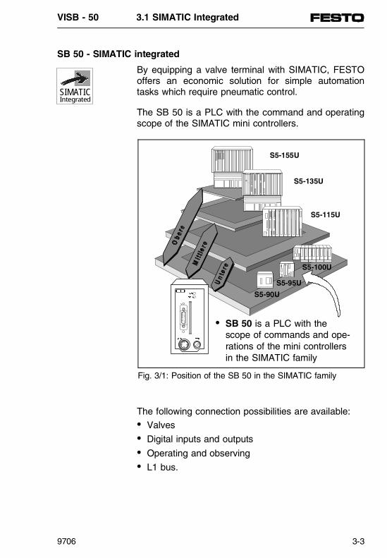
SB 50 - SIMATIC integrated
By equipping a valve terminal with SIMATIC, FESTOoffers an economic solution for simple automationtasks which require pneumatic control.
The SB 50 is a PLC with the command and operatingscope of the SIMATIC mini controllers.
The following connection possibilities are available:• Valves• Digital inputs and outputs• Operating and observing• L1 bus.
SIMATICIntegrated
• SB 50 is a PLC with thescope of commands and ope-rations of the mini controllersin the SIMATIC family
S5-155U
S5-135U
S5-115U
S5-100U
S5-95U
S5-90U
Fig. 3/1: Position of the SB 50 in the SIMATIC family
VISB - 50 3.1 SIMATIC Integrated
9706 3-3

Simple programming
The proven STEP 5 software is available for pro-gramming in the three languages ladder diagram,function chart and statement list. Programming ismade with the programmers of the SIMATIC family.
In this way you can:- Make use of existing programs- Transfer programs- Use your experience with STEP 5 and- Carry out commissioning as is customary.
Operating and display elements
Fig. 3/2: SB 50: Display/operating elements and interfaces
R U N
ST OP
2 4 VD C F U SE
PG
SIEMENS
LED for control
Fuse for sensorconnections
Diagnosticinterface
Mains supply
VISB - 50 3.1 SIMATIC Integrated
3-4 9706

3.2 INTERNAL OPERATING METHOD
PN
350
647
VISB - 50 3.2 Internal operating method
9706 3-5

Contents
3.2 INTERNAL OPERATING METHOD Function units ..................................................3-7
v:\sb50-gb\sys-sb50\sb5-k32.chpv:\sb50-gb\sys-sb50\sb5-k32.chp
VISB - 50 3.2 Internal operating method
3-6 9706

3.2 INTERNAL OPERATING METHOD
The following chapter describes how the SB 50 processes your program.
Function units
SB 50
CPU
Calculator Operatingsystem(ROMmemory)
Internalprogrammemory(RAM)
Memorymodule(EEPROM)
Controller
PII
TimersCountersFlags
PIQ
Serial interface
Input modules Valves
Output modules
FESTOmodules
FESTO-Periphery bus
Fig. 3/3: Function units SB 50
VISB - 50 3.2 Internal operating method
9706 3-7

• Program memory (EEPROM)In order to protect the control program of the SB 50 against loss in the event of a power failure,you must save it on an integrated EEPROM mod-ule. Programs thus saved on the EEPROM moduleare automatically copied into the internal programmemory when the voltage supply is switched on(see fig. 3/7). This internal program memory is a reserved area of the internal RAM of the CPU.
The internal RAM memory has the following char-acteristics:
- The memory contents can quickly be amended.- The memory contents are deleted if there is a
power failure.
• Operating system (ROM memory)The operating system contains system programs inwhich the design of user program, input and outputmanagement, distribution of memory space, datamanagement etc. are determined. The operatingsystem is specified and cannot be modified.
• Process image table (PII, PIO)The signal states of the inputs and outputs arestored in the CPU in "Process image tables."These process image tables are reserved areas inthe RAM memory of the CPU.
There are separate process image tables for inputand output modules:- The process image inputs table (PII) and- The process image outputs table (PIO).
SIMATICIntegrated
VISB - 50 3.2 Internal operating method
3-8 9706

• Serial interfaceConnection for programmers, operating and obser-vation units. The SB 50 can also be connected asslave on the SINEC L1 bus.
PLEASE NOTEThe programmer interface has been designed as apassive interface. (e.g. PG605 cannot be used, anactive interface converter V 24 ⇔ TTY is requiredfor PCs).
• Timers, counters and flagsThe CPU makes internally available timers, coun-ters and flags which can be used by the controlprogram. The timers and counters can be set, re-set, started and stopped by the program. The valuesfor the timers and counters are stored in reservedareas of the RAM.
Information, e.g. intermediate results can be stored asflags in a further range of the RAM. The flags can beaddressed bit-by-bit, byte-by-byte or word-by-word.
If there is a power failure, some of the flags and counters in the internal RAM are saved in an inte-grated EEPROM. When the mains voltage is switchedon again, they are written back into the internal RAM.We then speak of remanent flags and remanentcounters.
The following table shows the number and remanencereaction (contents of internal memory are saved/notsaved) of the timers, counters and flags.
Operand Remanent Non-remanentFlags F0.0...F63.7 F64.0...F255.7Counters C0...C7 C8...C127Timers --- T0...T127
Table 3/1: Remanent and non-remanent operands
SIMATICIntegrated
VISB - 50 3.2 Internal operating method
9706 3-9
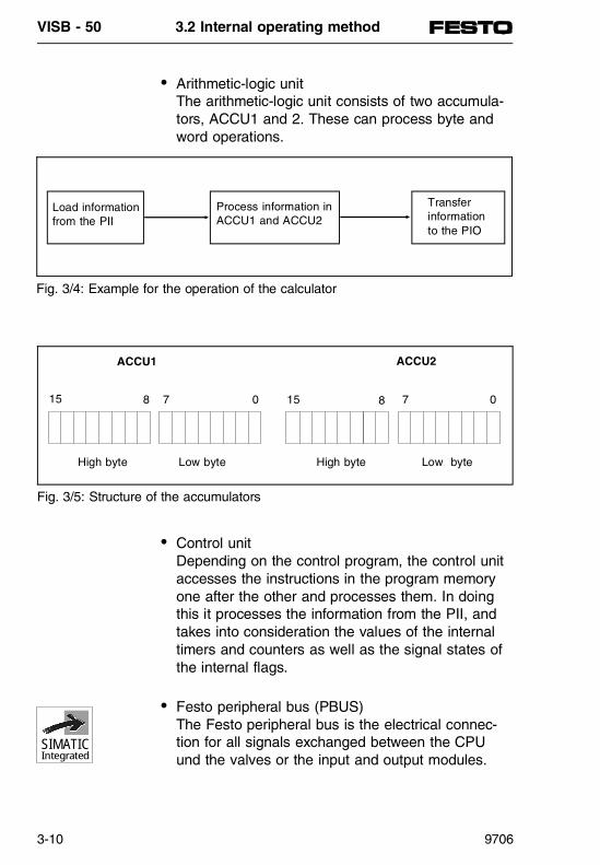
• Arithmetic-logic unitThe arithmetic-logic unit consists of two accumula-tors, ACCU1 and 2. These can process byte andword operations.
• Control unitDepending on the control program, the control unitaccesses the instructions in the program memoryone after the other and processes them. In doingthis it processes the information from the PII, andtakes into consideration the values of the internal timers and counters as well as the signal states ofthe internal flags.
• Festo peripheral bus (PBUS)The Festo peripheral bus is the electrical connec-tion for all signals exchanged between the CPUund the valves or the input and output modules.
Load informationfrom the PII
Process information in ACCU1 and ACCU2
Transferinformation to the PIO
Fig. 3/4: Example for the operation of the calculator
ACCU1
15 8 7 0
High byte Low byte High byte Low byte
ACCU2
15 8 7 0
Fig. 3/5: Structure of the accumulators
SIMATICIntegrated
VISB - 50 3.2 Internal operating method
3-10 9706

3.3 COMMISSIONING
PN
350
647
VISB - 50 3.3 Commissioning
9706 3-11

Contents
3.3 COMMISSIONINGCommissioning and program test......................3-13Operating modes ...............................................3-13SB 50 overall reset ............................................3-14Commissioning a system...................................3-15Commissioning procedures ...............................3-17Loading the program into the SB 50 .................3-18Saving programs................................................3-20Operation without a battery ...............................3-21Signal status display STATUS ..........................3-22Signal status display STATUS VAR..................3-22Controlling variables FORCE VAR....................3-22Special features .................................................3-23Search................................................................3-24
VISB - 50 3.3 Commissioning
3-12 9706

3.3 COMMISSIONING AND PROGRAM TEST
This chapter contains instructions on commissioning,the program test and operation of the SB 50.
Operating modes• Changing the operating mode
A change can be made from one operating modeto another as follows:- by a programmer- by faults which bring the SB 50 into the operat-
ing mode "STOP".
After POWER ON, the terminal initially goes intothe RUN mode. If an error is present, the SB 50then goes directly into the STOP mode.
• Operating mode "STOP"The program will not be processed.- The values of timers, counters, flags and pro-
cess diagrams, which are current at the momentthe "STOP" status is reached, will be maintained.
- Valves and output modules will be blocked (signal status "0").
PG
SIEMENSRU N
STOP
Operating modedisplay
(green LED ⇒ RUN)
Operating modedisplay
(red LED ⇒ STOP)
Fig. 3/6: Operating field of the SB 50
SIMATICIntegrated
VISB - 50 3.3 Commissioning
9706 3-13
- In the transition from "STOP" to "RUN", the pro-cess diagrams, timers and the non-remanentflags and counters will be set at "zero".
• Operating mode "RUN"- The program is processed cyclically.- Times started in the program run out.- The signal states of the input modules are
loaded.- The valves and output modules are addressed.- Operating mode "RUN" can also be set after
"GENERAL RESET", i.e. with an empty programmemory.
• Operating mode "START"- The DB1 is processed by the operating system
and the parameters are transferred.- The start organisation blocks OB21 or OB22 are
processed.- The start duration is not limited in time as the
cycle time monitoring is not activated.- Time-controlled program processing is not
possible.- The valves, input and output blocks are blocked
during the start.
SB 50 Overall reset
Before entering a new program, we recommend thatyou perform the function "Overall reset". The followingwill then be deleted:- the program memory of the SB 50
(RAM and EEPROM),- all data (flags, times and counters) as well as- all error identifiers.
SIMATICIntegrated
VISB - 50 3.3 Commissioning
3-14 9706

The OVERALL RESET function is triggered by thereset of all modules of the SB 50 (see programmermanual) and is possible only in the STOP mode.
PLEASE NOTEWithout "Overall reset", information will be main-tained even if the program is overwritten.
Commissioning a system
The following section contains instructions on projectplanning and on how to commission a system withprogrammable logic controllers.
Instructions on project planning and installation
Since the product when used is usually an integralpart of a system, these instructions should serve as aguide for safe integration of the product.
WARNING
• The relevant safety and accident preventionregulations must always be observed.
• If used with a fixed connection (non-moveabledevices and systems) without an all-polepower-off switch and/or fuses, a power-offswitch must be fitted into the installation; thedevice must be connected to a PE conductor.
• If using devices operated by a mains switch,check before commissioning whether the ratedvoltage range set corresponds to the localmains power supply.
• With a 24 V supply, the low voltage must becorrectly separated from the mains supply.
VISB - 50 3.3 Commissioning
9706 3-15

WARNING (continued)
• Fluctuations in the mains voltage from the ratedvalue must not exceed the tolerance limitsquoted in the technical specifications, otherwisethere may be operating failures and dangeroussituations on the electronic modules/device.
• Measures must be taken, so that a program canbe continued properly after voltage failures andinterruptions. Dangerous operating conditionsmust not occur, not even briefly. If necessary"emergency stop" must be used.
• Emergency stop devices as per EN 60204, IEC 204 (VDE 0113) must be effective in all operating modes of the automation device. Un-locking the emergency stop device must not trig-ger any uncontrolled or undefined new start.
• Connection and signal cables must be installedso that inductive and capacitive influences donot impair the automation functions.
• Automation devices and their operating elementsmust be fitted so that they are sufficiently pro-tected against unauthorized handling
• In order that a cable or core fracture on thesignal side does not lead to undefined statesin the automation device, appropriate safetymeasures must be taken in both the hardwareand the software in the I/O coupling.
VISB - 50 3.3 Commissioning
3-16 9706

Commissioning procedures for the SB 50
Prerequisites,work steps
Remarks Displays
System and SB 50 mustbe switched off• Check mechanical
configuration and wiring
Observe installationguidelines as per VDE 0100/VDE 0113and VDE 0160.
Test periphery• Switch on power supply
and load power unitfor SB 50
• Connect programmerto SB 50
• Overall reset SB 50• SB 50 at "RUN" • Operate signal genera- tors one after the other• Switch on power supply
for valves and outputs• Control outputs with programmer function "FORCE VAR"
Programmer functionProgrammer functionWith progr. function"STATUS VAR" theInput signals can beobserved in PII.The switching states ofthe valves and actuatorsare modified
• Red LED of SB 50 lights up
• Green LED of SB 50 l lights up
Test program• SB 50 at "STOP"• Transfer user program
from programmer to SB 50
• SB 50 at "RUN"• Test program and
correct if necessary• SB 50 at "STOP"
• Save program with"COMPRESS" on EEPROM
• SB 50 in "RUN"
Programmer functionProgrammer function
Programmer functionProgrammer function
Programmer function
Programmer function
System is in operation
• Red LED of SB 50 lights up
• Green LED of SB 50lights up
• Red LED of SB 50 lights up
• Red LED flickers and then lights up
Table 3/2: Commissioning the SB 50
VISB - 50 3.3 Commissioning
9706 3-17

Loading a program into the SB 50
During loading, a program is transferred to the pro-gram memory of the SB 50. As first possibility, youcan load a program from a connected programmer(on-line operation). The exact instructions are to befound in the manual for your programmer.
The second possibility, the automatic loading from amemory block, is described overleaf.
During automatic loading, the program is copied fromthe integrated EEPROM memory block into the pro-gram memory of the automation unit. Only validblocks are loaded.
SIMATICIntegrated
VISB - 50 3.3 Commissioning
3-18 9706

SB 50 switched off
Power on
System initialization
Copy blocksEEPROM ⇒ RAM
Error ?
Red LED flickers
Blocks in RAM of SB 50
RUN-info in EEPROM ?
Green LED lights up
SB 50 in RUN
SB 50 in STOP
Red LED lights up
Red LED blinks
SB 50 in STOP(carry out error
diagnosis )
No
Yes
No
Yes
Fig. 3/7: Procedure for "Load program from integrated EEPROM into SB 50"
VISB - 50 3.3 Commissioning
9706 3-19

Saving the program
During saving, a program is copied from the programmemory of the SB 50 into an integrated EEPROMmemory block. Only valid blocks are saved. The inte-grated default-DB1, also belongs here, as soon as ithas been modified.
Power on
SB 50 in operating mode STOP
COMPRESS programmer function
Copy blockRAM ⇒ EEPROM
Error ? Red LED blinks
Carry outerror diagnosis
Yes
No
Red LED flickers:Program is saved
Red LED lights up
Program savedon EEPROM
Fig. 3/8: Procedure for "Save program from RAM to EEPROM memory block"
SIMATICIntegrated
VISB - 50 3.3 Commissioning
3-20 9706

Operation without a backup battery
In addition to the RAM, an EEPROM has also beenfirmly installed for data saving. This EEPROM enablesthe SB 50 to be operated without a battery and fullymaintenance-free. If there is an interruption of theoperating voltage, the remanent operands (see table3/1) are transferred from the RAM to the EEPROMand are written back into the RAM when the operatingvoltage is switched on again. The remaining non-re-manent operands are set at zero.
When the voltage supply is switched on again, theblocks, i.e. the program, are also written from the EEPROM into the RAM. The blocks can be written inoperating mode STOP from the RAM into the EEPROMby means of the programmer function COMPRESS.
Data blocks are not saved in the EEPROM after inter-ruption of the operating voltage.
DB
FBSB
PBOB
Data blocks
Program blocks
FlagsCounters
Timers T127
C127 Y64Y63FY0
C8C7C0T0
RAM EEPROM
C7C0
FY63 FY0
OBPB
SBFB
DB
FY255
Compress. programmer function
Power on
Power on
Power off
Fig. 3/9: RAM-EEPROM
SIMATICIntegrated
VISB - 50 3.3 Commissioning
9706 3-21

Like the other blocks, the data blocks are also writtenin operating mode STOP from the RAM into the EEPROM by means of the programmer functionCOMPRESS. When the operating voltage is switchedon again, the values stored in the EEPROM are co-pied into the RAM and any values formed in the pro-cess are overwritten.
PLEASE NOTEData blocks are not remanent.The resulting start reaction must be taken into account at all costs when the program is created.
Program-dependent signal status display "STATUS"
This test function shows the current signal states andthe RLO of the individual operands during programprocessing. Corrections to the program can also becarried out.
Direct signal status display "STATUS VAR"
This test function shows the status of any operand(inputs, outputs, flags, data words, counters or timers)at the end of program processing. Information frominputs and outputs is taken from the process imagetable of the selected operands.
Controlling variables "FORCE VAR"
The process image table of the operands is modifiedin operating mode RUN of the SB 50. The followingvariables can be modified: I, Q, F, T, C and D.
Program processing with the modified process vari-ables is carried out in operating mode RUN. In thefurther course of the program, they can be modifiedagain, without any return message. The process vari-ables are controlled asynchronously to the program.
VISB - 50 3.3 Commissioning
3-22 9706

Special features• The variables I, Q and F can be modified bit-by-bit,
byte-by-byte or word-by-word in the process dia-gram.
• In the case of the variables T and C in the formatKM and KH- Enter also "YES" in the mask PRESETTINGS in
the field SYSTEM COMMANDS (with screen pro-grammers).
- Note the control of the edge flags.• The signal status display is interrupted if there is
an incorrect format entry or operand entry. The pro-grammer then shows the message "CONTROLNOT POSSSIBLE."
Information on accessing the test functions on theprogrammer are to be found in the appropriate pro-grammer manuals.
VISB - 50 3.3 Commissioning
9706 3-23

Search
The search is used to look for certain terms in theprogram. These terms are then listed on the pro-grammer display. Amendments to the program can bemade at this stage.
Searches can be made in the following programmerfunctions:- INPUT- OUTPUT- STATUS
Possible search terms:- Statements (e.g. A I32.0) - Operands (e.g. Q32.5) - Labels (e.g. X 01)
Only possible in function blocks- Addresses (e.g. 0006H)
PLEASE NOTEThe search is made differently in the individual pro-grammers and is described in detail in the appropri-ate operating instructions.
VISB - 50 3.3 Commissioning
3-24 9706

3.4 DIAGNOSTICS AND ERROR TREATMENT
PN
350
647
VISB - 50 3.4 Diagnostics and error treatment
9706 3-25

Contents
3.4 DIAGNOSTICS AND ERROR TREATMENT Valve terminal diagnosis ..................................3-27 Reading the diagnostic byte.............................3-28 Error message by means of LEDs...................3-28 Faults in the SB 50...........................................3-29 Interruption analysis .........................................3-30 Error in copying a program ..............................3-31 Abbreviations in ISTACK..................................3-31 Program errors .................................................3-32
VISB - 50 3.4 Diagnostics and error treatment
3-26 9706
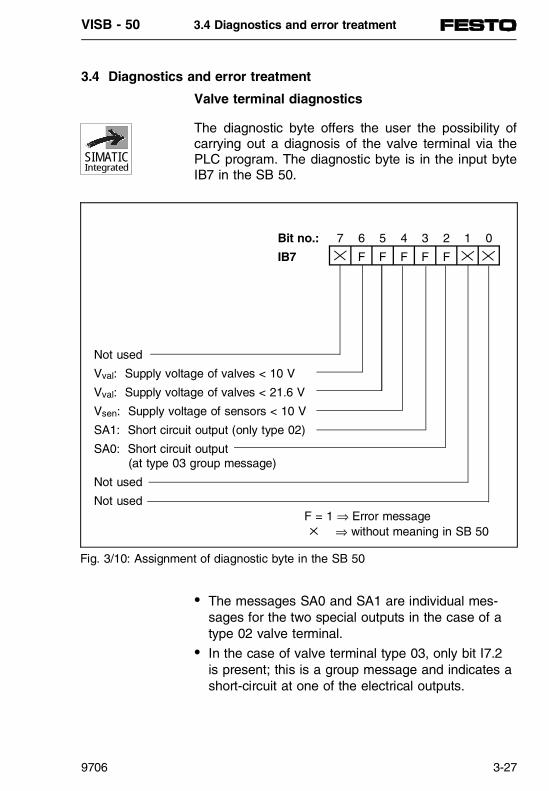
3.4 Diagnostics and error treatment
Valve terminal diagnostics
The diagnostic byte offers the user the possibility ofcarrying out a diagnosis of the valve terminal via thePLC program. The diagnostic byte is in the input byteIB7 in the SB 50.
• The messages SA0 and SA1 are individual mes-sages for the two special outputs in the case of atype 02 valve terminal.
• In the case of valve terminal type 03, only bit I7.2is present; this is a group message and indicates ashort-circuit at one of the electrical outputs.
Bit no.: 7 6 5 4 3 2 1 0
IB7 F F F F F
Not used
Vval: Supply voltage of valves < 10 V
Vval: Supply voltage of valves < 21.6 V
Vsen: Supply voltage of sensors < 10 V
SA1: Short circuit output (only type 02)
SA0: Short circuit output (at type 03 group message)
Not used
Not usedF = 1 ⇒ Error message ⇒ without meaning in SB 50
Fig. 3/10: Assignment of diagnostic byte in the SB 50
SIMATICIntegrated
VISB - 50 3.4 Diagnostics and error treatment
9706 3-27

Notes on diagnostics information:• Vsen:
Operating voltage for the sensors is below 10 V.This error occurs when the fuse for the sensorshas blown.
• Vval: The valves are designed for an operating voltageof 24 V ± 10 % (21.6...26.4 V). If the voltage at Pin 2 of the mains socket falls below 21.6 V, thebit Vval is set. The cause may be overload of thepower supply unit or a supply cable which is toolong.
• Vout:The operating voltage of the valves and electricaloutputs is below 10 V. Pin 2 of the power supplyconnection is monitored. The cause may be anopen-circuit line, a blown fuse or an interruptioncaused by an EMERGENCY STOP; see also Vval.
Reading the diagnostic byte
The data stored in the diagnostic byte can be readand evaluated in the control program by means of bi-nary operations (e.g. A I7.2) or with load operations(e.g. L IB7).
Error message by means of LEDs
If there is an error in the operating method of yourcontroller, this will be shown in the operating field ofthe programmer (see table 3/3).
If both LEDs light up, the SB 50 has started.
VISB - 50 3.4 Diagnostics and error treatment
3-28 9706

Faults in the SB 50• Analysis function "ISTACK"
The interruption stack is an internal memory of theSB 50. The causes of faults are stored here. Ifthere is a fault, a bit will be stored in the appropri-ate byte of the memory. The memory can be readbyte-by-byte via the programmer. This can be ac-cessed in the menu on the programmer in operat-ing mode "STOP". The sequence of keys can befound in the programmer manual.
PLEASE NOTEOnly the ISTACK bytes 1...6 (first diagram) can beoutput in operating mode RUN. There is no inter-ruption which could cause the SB 50 to enter the"STOP" status. The control bits are output in bytes1...6 (first diagram).
Error display Error analysisSB 50 in STOP,red LED lights up
Fault in SB 50Carry out interrupt analysis with programmer.
AG in STOP,red LED blinks
Error in loading or saving the program on EEPROM.Carry out interrupt analysis with programmer.
Programmer inRUN, green LEDlights up,incorrect operation
Program errororfault in peripheryCarry out fault analysis
Table 3/3: Error display and error analysis
VISB - 50 3.4 Diagnostics and error treatment
9706 3-29

Interruption analysis
ISTACK-display
Cause of error Elimination
SUF Substitution error Correct FB call
TRAF Transfer error- Programmed DB with DW no.
greater than data block length- Programmed data block
command without previousDB opening
Eliminate program error
NNN - Command cannot be decoded- Bracket level exceeded ()- Parameter exceeded- Direct periphery access in
cyclic program processing
Eliminate program error
NINEU No restart possible Overall reset, load programSTS Stop by programmer or software
stop by S5 command (STP)STUEB Block stack overrun
The max. nesting depth (16) isexceeded
Eliminate program error
NAU Power failure Stabilize supply voltageQVZ Acknowledgement delay
Error in decentral periphery orin L2-DP interface
Check decentral periphery blocks and if necessary replace (SD15/16)
ZYK Cycle time exceededThe program processing timeexceeds the cycle monitoring timeCause:- program too long
Check program for endlessloops or shorten
PEU Periphery not clearError in local periphery
Check valve terminalperiphery (SD14)
ASPFA EEPROM error- Maximum number of
write cycles reached- Error in write cycle
Replace SB 50 Try again
Table 3/4: Interrupt analysis
VISB - 50 3.4 Diagnostics and error treatment
3-30 9706
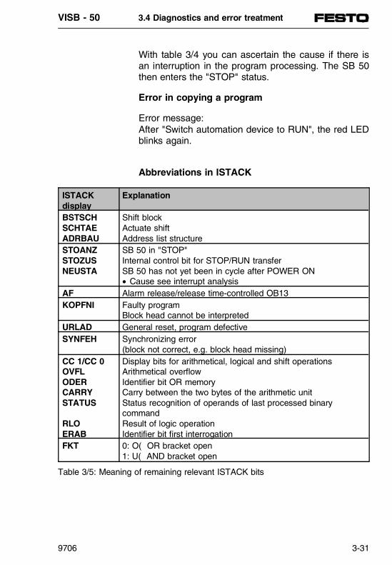
With table 3/4 you can ascertain the cause if there isan interruption in the program processing. The SB 50then enters the "STOP" status.
Error in copying a program
Error message: After "Switch automation device to RUN", the red LEDblinks again.
Abbreviations in ISTACK
ISTACKdisplay
Explanation
BSTSCHSCHTAEADRBAU
Shift blockActuate shiftAddress list structure
STOANZSTOZUSNEUSTA
SB 50 in "STOP"Internal control bit for STOP/RUN transferSB 50 has not yet been in cycle after POWER ON• Cause see interrupt analysis
AF Alarm release/release time-controlled OB13KOPFNI Faulty program
Block head cannot be interpretedURLAD General reset, program defectiveSYNFEH Synchronizing error
(block not correct, e.g. block head missing)CC 1/CC 0OVFLODERCARRYSTATUS
RLOERAB
Display bits for arithmetical, logical and shift operationsArithmetical overflowIdentifier bit OR memoryCarry between the two bytes of the arithmetic unitStatus recognition of operands of last processed binarycommand Result of logic operationIdentifier bit first interrogation
FKT 0: O( OR bracket open1: U( AND bracket open
Table 3/5: Meaning of remaining relevant ISTACK bits
VISB - 50 3.4 Diagnostics and error treatment
9706 3-31

Program errors• Determining the error address.
The STEP address counter (SAC) in ISTACK(bytes 25, 26) gives the absolute memory addressof the STEP 5 instruction in the programmer whichcaused the programmer to enter the "STOP"status, or it indicates the block start address of theincorrect block. The relevant block start addresscan be found with the programmer function "DIRAG". If the instruction is not permitted, the program-mer will interrupt the program processing and enterthe "STOP" status with the error message "NNN".The STEP address counter stands on the absoluteaddress of the next, still unprocessed instruction oron the block start address of the incorrect block inthe program memory.
• Program tracing with the "BSTACK" function.During program processing, the following informa-tion about jump functions is entered in the blockstack (BSTACK):- the data block which was valid before the module was exited;- the absolute block start address - this gives the memory address of the block start in the program memory.
This information can be accessed with the pro-grammer function "BSTACK " in operating modeSTOP, if the SB 50 enters the STOP status due toa fault.
There is no BSTACK regeneration after POWEROFF.
• System parametersThe system parameters (e.g. software status) ofthe SB 50 can be read with the programmer func-tion "SYSPAR" (see programmer manual).
SIMATICIntegrated
VISB - 50 3.4 Diagnostics and error treatment
3-32 9706

3.5 ADDRESSING
PN
350
647
VISB - 50 3.5 Addressing
9706 3-33

Contents
3.5 ADDRESSING Structure of process image table .....................3-35 Alarm process diagrams and timecontrolled program processing in OB13.............................................................3-36 Address allocation in RAM memory.................3-37
VISB - 50 3.5 Addressing
3-34 9706

3.5 ADDRESSING
The inputs and outputs on the valve terminal are de-scribed herein as local periphery. In order that thevalves and the inputs and outputs of the local peri-phery can be addressed, they must be assigned withcertain addresses. The addresses of the local peri-phery are orientated around the physical arrangementof the valve terminal. The various valve terminalshave a different distribution and arrangement of theaddresses. Please refer to Part 2 for the valid ad-dressing.
Structure of process image table
Information about the inputs is stored in the processimage input table (PII), and information about the out-puts is stored in the process image output table (PIQ).
The PII and the PIQ of the local periphery cover arange of 8 bytes each in the RAM memory.
Byte address inPII and PIQ
Inputs Outputs
0...6 IB0...6 Local inputs
QB0...7 Local outputs
7 IB7 Local valveterminaldiagnostics
Table 3/6: Structure of process input image table (PII) and process output imagetable (PIQ)
SIMATICIntegrated
VISB - 50 3.5 Addressing
9706 3-35

Alarm process image tables and time-controlledprogram processing in OB13
The SB 50 offers the possibility of time-controlled pro-gram processing for which the OB13 must be pro-grammed. This is accessed periodically. The fre-quency of access can be set (see chapter 3.8).• Within the time-controlled program processing, you
can use the operand identifiers "PB", "PY", "PW"on the local periphery.
PLEASE NOTE The load and transfer operations with the operandidentifiers "PB", "PY", "PW" on the local addressesdo not effect a direct access to the periphery, butrepresent an image table of the PIQ/PII.
• The alarm process image tables are only used in time-controlled program processing.
• The alarm process image tables and the "normal" process image tables are structured identically.
VISB - 50 3.5 Addressing
3-36 9706
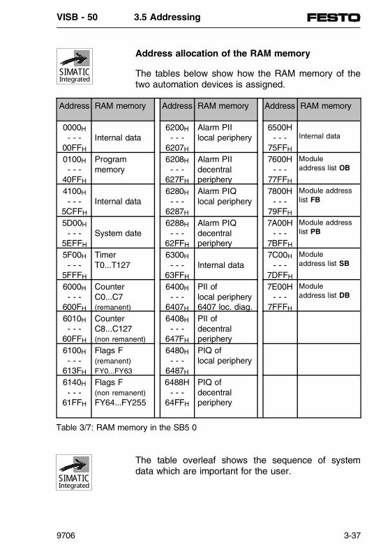
Address allocation of the RAM memory
The tables below show how the RAM memory of thetwo automation devices is assigned.
The table overleaf shows the sequence of systemdata which are important for the user.
SIMATICIntegrated
SIMATICIntegrated
Address RAM memory Address RAM memory Address RAM memory
0000H
- - -00FFH
Internal data6200H
- - -6207H
Alarm PII local periphery
6500H- - -
75FFH
Internal data
0100H
- - -40FFH
Programmemory
6208H
- - -627FH
Alarm PIIdecentralperiphery
7600H- - -
77FFH
Module address list OB
4100H
- - -5CFFH
Internal data6280H
- - -6287H
Alarm PIQlocal periphery
7800H- - -
79FFH
Module addresslist FB
5D00H
- - -5EFFH
System date6288H
- - -62FFH
Alarm PIQ decentralperiphery
7A00H- - -
7BFFH
Module addresslist PB
5F00H
- - -5FFFH
TimerT0...T127
6300H
- - -63FFH
Internal data7C00H
- - -7DFFH
Module address list SB
6000H
- - -600FH
CounterC0...C7(remanent)
6400H
- - -6407H
PII oflocal periphery6407 loc. diag.
7E00H- - -
7FFFH
Module address list DB
6010H
- - -60FFH
CounterC8...C127(non remanent)
6408H
- - -647FH
PII of decentral periphery
6100H
- - -613FH
Flags F (remanent)FY0...FY63
6480H
- - -6487H
PIQ oflocal periphery
6140H
- - -61FFH
Flags F (non remanent)FY64...FY255
6488H- - -
64FFH
PIQ ofdecentralperiphery
Table 3/7: RAM memory in the SB5 0
VISB - 50 3.5 Addressing
9706 3-37
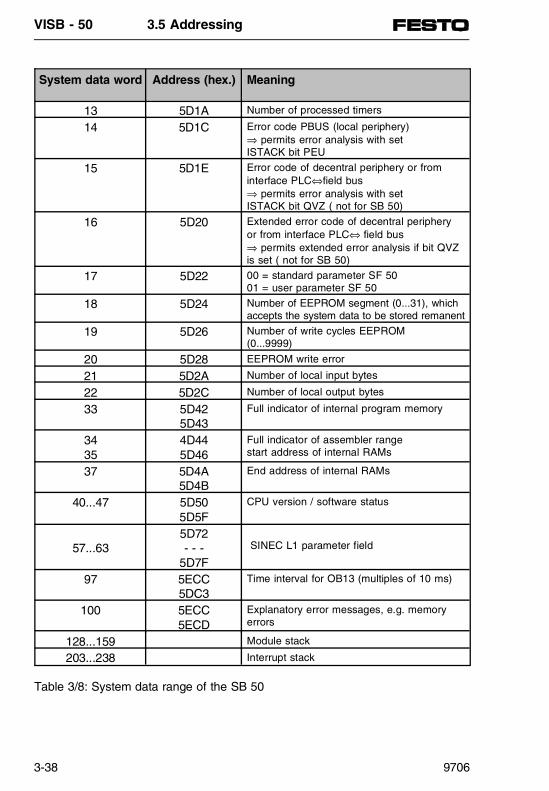
System data word Address (hex.) Meaning
13 5D1A Number of processed timers
14 5D1C Error code PBUS (local periphery)⇒ permits error analysis with set ISTACK bit PEU
15 5D1E Error code of decentral periphery or frominterface PLC⇔field bus ⇒ permits error analysis with set ISTACK bit QVZ ( not for SB 50)
16 5D20 Extended error code of decentral peripheryor from interface PLC⇔ field bus ⇒ permits extended error analysis if bit QVZis set ( not for SB 50)
17 5D22 00 = standard parameter SF 5001 = user parameter SF 50
18 5D24 Number of EEPROM segment (0...31), whichaccepts the system data to be stored remanent
19 5D26 Number of write cycles EEPROM(0...9999)
20 5D28 EEPROM write error
21 5D2A Number of local input bytes
22 5D2C Number of local output bytes
33 5D425D43
Full indicator of internal program memory
3435
4D445D46
Full indicator of assembler rangestart address of internal RAMs
37 5D4A5D4B
End address of internal RAMs
40...47 5D505D5F
CPU version / software status
57...635D72- - -
5D7F
SINEC L1 parameter field
97 5ECC5DC3
Time interval for OB13 (multiples of 10 ms)
100 5ECC5ECD
Explanatory error messages, e.g. memoryerrors
128...159 Module stack
203...238 Interrupt stack
Table 3/8: System data range of the SB 50
VISB - 50 3.5 Addressing
3-38 9706

3.6 INTRODUCTION TO STEP 5
PN
350
647
VISB - 50 3.6 Introduction to STEP5
9706 3-39

Contents
3.6 INTRODUCTION TO STEP 5Creating a program .........................................3-41Representation types.........................................3-42Operand ranges.................................................3-44Program structure..............................................3-45Block types.......................................................3-47Programming .....................................................3-47Organization block (OB) ....................................3-48Program blocks (PB) .........................................3-50Step blocks (SB)................................................3-50Function blocks (FB)..........................................3-50Block header......................................................3-51Creating a function block...................................3-51Calling a function block .....................................3-54Programming data blocks..................................3-56Program processing with data blocks ...............3-57Function of data block 1....................................3-58Program processing........................................3-59Programming possibilities..................................3-59START programming.........................................3-60Cyclic program processing ................................3-63Time-controlled program processing .................3-64Prerequisites for time-controlled program processing ...........................................3-64Processing blocks..............................................3-67Program modifications .......................................3-67Block modifications ............................................3-67Compressing the program memory...................3-68Representing numbers....................................3-69
VISB - 50 3.6 Introduction to STEP5
3-40 9706

3.6 INTRODUCTION TO STEP 5
This chapter describes how to program automationtasks with the SB 50. An explanation is given of howprograms are created and of the blocks which can beused to form the links in a program. You will also finda summary of the various number representationsrecognised by the programming language STEP 5.
Creating a program
With programmable logic controllers (PLC) automationtasks are formulated as control programs. Here theuser determines in a series of instructions, how theSB 50 is to control the system. In order that the auto-mation device can "understand" the program, the lat-ter must be written in a particular language, i.e. theprogramming language, in accordance with fixed rules. The programming language STEP 5 has beendeveloped for the SIMATIC S5 family.
VISB - 50 3.6 Introduction to STEP5
9706 3-41

Representation types
The following representation types are possible withthe uniform programming language STEP 5 for the SI-MATIC S5 series:• Statement list (STL): The STL presents the pro-
gram as a sequence of command abbreviations.An instruction is composed as follows:
The operation tells the SB 50, what it must do withthe operand. The parameter specifies the address ofan operand.• Control system flow chart (CSF): In the CSF the
logical links are represented graphically as sym-bols.
• Ladder diagram (LDR): In the LDR the control func-tions are represented graphically with symbols ofthe circuit diagram.
• GRAPH5: This representation type serves for de-scribing the structure of sequence controllers.The "fast version" can be used in the SB 50.
Each representation type has special characteristics.A program block which has been programmed in STLcannot be output without further treatment in CSF orLDR. Also, the graphical representation types are notcompatible with each other.
002: A I 2.0
OperationOperand
ParameterOperandidentifierRelative address of instruction
in relevant block
Fig. 3/11: Structure of an instruction
VISB - 50 3.6 Introduction to STEP5
3-42 9706

However, programs in CSF or LDR can always betranslated into STL. These statements are repre-sented below in the form of a sets diagram.
The programming language STEP 5 distinguishes be-tween three types of operations: • Basic operations• Supplementary operations• System operations
Table 3/10 contains further information on the indivi-dual operation types.
STL
LDRCSF
Fig. 3/12: Compatibility between programming languages
Programming language STEP 5
Basic operations
Supplementaryoperations
System operations
Area of application In all blocksOnly in function blocks
Only in function blocks
Representation STL, CSF, LDR STL STL
Special featuresOnly for users withgood knowledge of the system.
Table 3/9: Comparison of operation types
VISB - 50 3.6 Introduction to STEP5
9706 3-43
Operand ranges
The programming language STEP 5 recognises thefollowing operand ranges:
I (Inputs) Interfaces from the process to theautomation device
Q (Outputs) Interfaces from the automation deviceto the process
F (Flag) Memory for binary intermediate results
D (Data) Memory for digital intermediate results
T (Timers) Memory for implementing timers
C (Counter) Memory for implementing counters
P (Periphery) Interface from the process to theautomation device
K (Constants) Fixed numerical values
OB PB SB FB DB
(blocks) Aids for structuring the program
VISB - 50 3.6 Introduction to STEP5
3-44 9706

Program structure
For solving complex tasks, the user should divide thecomplete program into sensible individual self-con-tained program parts (blocks).
This procedure offers the user the following advan-tages:• Simple and easy-to-understand programming even
of larger programs. • Possibility of standardizing program parts• Simple possibilities of amendment• Simple program test• Simple commissioning• Subprogram techniques (accessing a block from
different points)
There are five blocks types in the programming language STEP 5:• Organization blocks (OB)
Organization blocks manage the control program.• Program blocks (PB)
The control program is divided up according tofunctional or technological viewpoints in programblocks.
• Step blocks (SB) Step blocks are special program blocks for pro-gramming sequence controllers. They are treatedlike program blocks.
• Function blocks (FB) Function blocks are special program blocks. Fre-quently reoccurring or particularly complex pro-gram parts (e.g. message or calculating functions)are programmed in function blocks. They can beparametrized and possess an extended scope ofoperations (e.g. jump operations within a block).
VISB - 50 3.6 Introduction to STEP5
9706 3-45

• Data blocks (DB) The data blocks are used for storing datas whichare required for processing the control program.These are e.g. actual values, limit values or texts.A block can be exited with block accesses and ajump made to another block. Program, functionand step blocks can therefore be nested in up to16 levels.
PLEASE NOTEWhen calculating the nesting depth, you must takeinto account that, under certain circumstances, thesystem program in the SB 50 can itself access anorganisation block (e.g. OB13).
The complete nesting depth is the sum of the nestingdepths of the cyclic (OB1) and time-controlled (OB13)program processing. If there are more than 16 levelsof nesting, the SB 50 will enter the STOP status withthe error message "Block stack overflow STUEB".
OB1 PB1
PB2
PB10
FB110
FB111
FB60
FB81
Level 1 Level 2 Level 3 • • • Level 16
• • •
FB7
DB2
Level 4
Fig. 3/13: Nesting depth
VISB - 50 3.6 Introduction to STEP5
3-46 9706

Block types
The most important features of the individual block types are to be found in the table below.
Programming
The blocks are programmed as follows (except fordata blocks):- Specify block type (e.g. PB),- Specify block number (e.g. 27),- Enter the instructions of the control program, - Terminate the block with instruction "BE".
OB PB SB FB DB
Number 2561
OB1...OB255256
PB0...PB255256
SB0...SB2552562
FB0...FB2552543
DB2...DB255
Length (max) 8 kByte 8 kByte 8 kByte 8 kByte 256Data words
Operationscope
Basicoperations
Basicoperations
Basicoperations
Basicoperations,suppl.operations,systemoperations
Bit pattern
Numberstexts
Programminglanguages
STL, CSF,LDR
STL, CSF,LDR
STL, CSF,LDR
STLCSF4, LDR4
Length of mod. head
5 words 5 words 5 words 5 words 5 words
1 Special OBs are accessed automatically from the operating system2 Function blocks have already been integrated in the operating system 3 Data blocks DB0 and DB1 are reserved4 As from V6.x STEP 5
Table 3/10: Comparison of block types
VISB - 50 3.6 Introduction to STEP5
9706 3-47

Organization blocks (OB)
Organization blocks form the interface between theoperating system and the control program. There arethree types of organization blocks.• An organization block is accessed cyclically from
the operating system (OB1) • Some of the organization blocks are event-control-
led or time-controlled, i.e. they are accessed by- STOP - RUN or POWER OFF - POWER ON
transition (OB21, OB22)- Time intervals (OB13)
• Some other organization blocks represent opera-ting functions (similar to the integrated functionblocks), which can be accessed by the control program (see chapter 3.8.1).
In the SB 50, you can program all organisation blockswith parameters from the permitted range (OB1...255).However, they must be accessed in the control pro-gram.
OB no. FunctionOB must be programmed by the user and is accessed by the program
OB1 Cyclic program processingAlarm-controlled program processing
OB13 Time-controlled program processingTreatment of start reaction
OB21 When switched on manually (STOP → RUN)OB22 When voltage is switched on again
OB has already been programmed, OB must be accessed by user
OB31 Cycle time triggeringOB251 PID control algorithm
Table 3/11: Summary of organisation blocks
VISB - 50 3.6 Introduction to STEP5
3-48 9706

The following diagram shows how to build up a struc-tured control program. It also makes clear the import-ance of the organization blocks.
Cyc
leS
tart
OB21/22
OB1
FB110PB1
FB111
Systemprogram
Organizationblocks
Controlprogram
Fig. 3/14: Example for the use of organization blocks
VISB - 50 3.6 Introduction to STEP5
9706 3-49

Program blocks (PB)
Self-contained program parts are programmed inthese blocks.
Special feature: The control functions can be represented graphicallyin program blocks.
Access
Program blocks are activated with the block accessesJU and JC. These operations can be programmed inall block types, except for data blocks. block accessesand terminations limit the RLO. However, it can betransferred and evaluated in the "newly accessed"block.
Step blocks (SB)
Step blocks are special forms of program blocks forprocessing sequence controllers. They are treated likeprogram blocks.
Function blocks (FB)
Frequently reoccurring or complex control functionsare programmed in function blocks.
Special features• Function blocks can be parametrized,• Actual parameters can be transferred when the
block is accessed,• There is an extended scope of operations
compared to other blocks,• The program with an extended scope of com-
mands can only be created and documented as STL.
VISB - 50 3.6 Introduction to STEP5
3-50 9706

With the SB 50 there are various designs of functionblocks. These are:• programmed by the user,• integrated in the operating system or • obtainable as a software package (standard
function blocks).
Block header
In addition to the block header, function blockspossess organisation information different from theother blocks.
The memory requirement of FBs is calculated from:• The block header (5 words)• The block name (5 words)• The block parameter in parametrizing
(3 words per parameter)
The FB-access occupies two words in the internalprogram memory; each parameter a further memoryword.
Creating a function block
In contrast to other blocks, FBs can be parametrized.The following specifications on the block parametersmust be programmed for the parametrization.• Names of the block parameter (formal operand)
- Each block parameter receives a designation(DES) under which, as a formal operand, it is re-placed by an actual operand when the functionblock is accessed.
- The name may contain max. four characters andmust begin with a letter. You can program up to40 parameters per function block.
VISB - 50 3.6 Introduction to STEP5
9706 3-51

• Type of block parameterThe following parameter types can be entered:- I Input parameter- Q (O) Output parameter- D Date- B Block- T Timer- C Counter
Output parameters are shown to the right of the func-tion symbol in the graphic representation. The otherparameters are on the left.
• Type of block parameterYou can specify the following types:- BI for operands with bit address- BY for operands with byte address- W for operands with word address- K for constant values
All specifications on the block parameters must be entered for parametrizing.
Block header(5 words)
Block name(5 words)
Block parameter(3 words per parameter)
Control program :A = IN 1:A = IN 2:= = OUT1
DES:DES:DES:
IN1IN2
OUT1
Para-meter
IIQ
Sortof
BIBIBI
Type
Name: EXAMPLE
Program example
Fig. 3/15: Programming of the FB with block parameter
VISB - 50 3.6 Introduction to STEP5
3-52 9706

Form ofparameter
Type of parameter Permitted actual operands
I, Q BI for an operand with bit address
BY for an operand with byte address
W for an operand with word address
I x.y InputsQ x.y OutputsF x.y Flags
IB x Input byteQB x Output byteFY x Flag byteDL x Data byte leftDR x Data byte rightPY x Periphery byte*
IW x Input wordOW x Output wordFW x Flag wordDW x Data wordPW x Periphery word*
D KM for a binary pattern (16 positions)KY for two byte-by-byte numbers in
the range 0 to 255KH for a hexadecimal pattern
(max. 4 positions)KS for a character
(max. 2 alphanumerical characters)KT for a time value (BCD time value) with pattern 1.0 to 999.3KC for a counter value (BCD) 0 to 999KF for a fixed-point number in the range
- 32768 to + 32767
Constants
B No type display permitted DBx Data block, commandADBx is processed
OBx Organisation blocksare accessed absolute
FBx Function blocks(only without parameter)are accessed absolute
PBx Program blocks are accessed absolute
SBx Step blocks are accessedabsolute
T No type display permitted T Timer; time value must beparametrized as date or as constant in FB
C No type display permitted C Counter; counter valuemust be parametrized asdate or as constant in FB
* Not for integrated FBs and only permitted within the time-controlled program processing (OB13)
Table 3/12: Form and type of block parameter with permitted actual operands
VISB - 50 3.6 Introduction to STEP5
9706 3-53

Calling a function block
Function blocks are stored, like the other blocks,under a certain number (e.g. FB47) in the internalprogram memory. The numbers 230...255 arereserved for integrated FBs. Accesses of FBs can beprogrammed in all blocks except data blocks.
The access of a function block consists of the follow-ing:• Access instruction
- JU FBx absolute access of FBx (Jump Unconditional...)
- JC FBx access of FBx, only when RLO=1(Jump Conditional ...)
• Parameter list (only necessary if block parametersare defined in the FB)
Function blocks can only be accessed if they havealready been programmed. When an FB-access isprogrammed, the programmer automatically requeststhe parameter list for the FB, providing block par-ameters have been defined in the FB.
Parametrizing a function block
The program in the function block specifies how theformal operands (parameters defined as "DES") are tobe processed.
As soon as you have programmed an access instruc-tion (e.g. JU FB2), the programmer superimposes theparameter list. The parameter list consists of thenames of the parameters, each followed by a colon(:). So-called actual operands must now be assignedto the parameters. Actual operands replace the formaloperands defined when the FBs are accessed, so thatthe FB "actually" works with the actual operands. Theparameter list must not contain more than 40 parame-ters.
VISB - 50 3.6 Introduction to STEP5
3-54 9706

PLEASE NOTEWhen a formal operand is later inserted in the pa-rameter list, all the formal operands will be movedone position. Programmed formal operands withinthe function block therefore modify their names andalso their function.
The diagram below shows a detailed example for par-ametrizing a function block.
Control program withfunction block
Function block
Fig. 3/16: Parametrizing a function block
:SPA FB5NAME :EXAMPLEIN1 :I0.0IN2 :I0.1OUT1 :Q0.0
:JU FB5NAME :EXAMPLEIN1 :I1.0IN 2 :I1.1OUT1 :Q0.1
PB3
NAME :EXAMPLEDES :IN1 I BIDES :IN2 I BIDES OUT1 Q BI
::A =ON1:A =ON2:= =OFF1:***
FB5
::A I0.0:A I0.1:= Q0.0::A I1.0:A I1.1:= Q0.1
Processed program
VISB - 50 3.6 Introduction to STEP5
9706 3-55

Data blocks (DB)
The data blocks are for storing data which are to beprocessed in the program.
The following types of data are permitted:• Bit pattern (representation of system states),• Numbers in hexadecimal, binary or decimal form
(time values, calculation results), • Alphanumeric characters (message texts).
Programming data blocks
Programming of a DB begins with the specification ofa block number between 2 and 255. The DB0 isreserved for the operating system; the DB1 for par-ametrizing internal functions. The data are storedword-by-word in this block. If the information containsless than 16 bits, the higher-value bits are filled upwith zeros. Data entry begins with data word 0 and iscontinued in ascending order. A data block can ac-cept up to 256 data words. The contents of the datawords can be accessed or modified with load or trans-fer operations.
In the SB 50, data blocks can also be created ordeleted in the control program.
Entry Stored values0000 : KH = A13C DW0 A13C0001 : KT = 100.2 DW1 21000002 : KF = +21874 DW2 5572
Fig. 3/17: Example of the contents of a data block
VISB - 50 3.6 Introduction to STEP5
3-56 9706

Program processing with data blocks• A data block must be accessed in the program
with the command C DBx (x=no.) before it can actually be used.
• A data block remains valid within a block, until another data block is accessed.
• If a jump is made back to the higher-order block,the data block valid before the block access isthen valid again.
• When OB1, 13, 21, 22 are accessed by the opera-ting system, no DB counts as being accessed.
PLEASE NOTEData blocks are not remanent and are overwrittenafter POWER ON by the initialization values storedin the EEPROM (see chapter 3.3).
:L DW1 :T DW2 :C DB11 :L DW1 :T DW2
: C DB3 : :JU PB20 : :
DB3
DB3
DB3
DB11
PB20PB7
Fig. 3/18: Validity range of data blocks
SIMATICIntegrated
VISB - 50 3.6 Introduction to STEP5
9706 3-57
Function of the DB1
The DB1 is intended for the use of special functionsin the SB 50 and is already integrated. It containspreset values (default values), which can either betransferred or modified by the user. The DB1 is evalu-ated once at the start, i.e. after POWER ON or after aSTOP - RUN transition (see chapter 3.8).
VISB - 50 3.6 Introduction to STEP5
3-58 9706

Program processing
Some of the organization blocks (OBs) take over thetask of structuring and managing the control program.
These OBs can be grouped according to the followingtasks:• OBs for START program processing• OB for cyclic program processing• OBs for time-controlled program processing
In addition, there are also OBs in the SB 50 whichoffer functions similar to the integrated function blocks(e.g. PID control algorithms). These OBs are de-scribed in the chapter "Integrated blocks."
A summary of all OBs is to be found in table 3/13.
Summary of theprogramming possibilities
In the following chapters you will see which specialorganization blocks the SB 50 makes available for theabove-listed tasks and what must be taken into ac-count in their programming.
Processing BlocksCyclic OB1Time-controlled OB13Integrated FBs FB230, 240...243, 250, 251GRAPH5 (fast version) SB0...255Parametrizable FBs FB0...255
Table 3/13: Programming possibilities
VISB - 50 3.6 Introduction to STEP5
9706 3-59

START program processing
In START processing, the operating system of the SB 50 automatically accesses a START-OB, providingit has been programmed.• OB21 (with manual new start)
or• OB22 (with automatic new start after POWER ON,
providing the SB 50 was previously in operatingmode RUN).
If you have programmed the START-OBs, this pro-gram will be processed before the cyclic program pro-cessing. It is therefore suitable e.g. for the (once only)presetting of certain system data. If the relevantSTART-OB is not programmed, the SB 50 will branchdirectly into the operating mode RUN.
Features of the start blocks (OB21, OB22)• The red and green LEDs light up• The timers are processed• The cycle monitoring is not activated
VISB - 50 3.6 Introduction to STEP5
3-60 9706

The two following examples show how a START-OBcan be programmed.
Delete process image tableof non-remanent timers,counters and flags,interpret the DB1
Delete process image tableof non-remanent timers,counters and flags,interpret the DB1
Programmer function RUN Return of power supply
Process the OB22Process the OB21
Release outputs
Process image input table
Process the OB1
Process image output table
Sar
t up
rou
tine
ST
AR
TC
yclic
pro
gram
pro
cess
ing
Fig. 3/19: Settings of the start reaction
VISB - 50 3.6 Introduction to STEP5
9706 3-61

Example STL Explanation
After the restoration of thepower supply, it must bechecked that the supplyvoltages for the decentralperiphery have reachedtheir nominal valuesbefore the cyclic programis executed. A timer loopis programmed in OB22for this purpose.
OB22 :AN T 1 ACCU1 is charged with atime constant of 5 s.Timer 1 is started.
At the end of the 5seconds, cyclic programexecution is started (inOB1).
:L KT 50.1
:SE T 1
:JU FB 1
Name :SCHLEIFE
BE
FB1Name :SCHLEIFE
LOOP :A T 1
:JC=LOOP
:BE
Example 1: Programming OB22
Example STL Explanation
After new start withoperating mode switch, the flag bytes 0...90 areto be assigned with value0. The other flag bytesare to be kept, as theycontain important machinefunctions.
:L KF 0 Value 0 is loaded intoACCU1 and transferred to flag words 0, 2, 4, 6,and 8.
:T MW 0
:T MW 2
:T MW 4
:T MW 6
:T MW 8
:BE
Example 2: Programming OB21
VISB - 50 3.6 Introduction to STEP5
3-62 9706

Cyclic program processing
The OB1 is accessed cyclically by the operating sys-tem. If you wish to program in a structured manner,you should only program jump functions (block ac-cesses) in the OB1. The blocks accessed (PBs, FBsand SBs) should contain completed function units, sothat understanding is simplified. Each cyclic programprocessing starts a monitoring period at the beginning(cycle trigger). If the cycle trigger is not touched againduring the monitoring period, the SB 50 will enter the"STOP" status and will block the outputs and valves.The monitoring time is approx. 300 ms. If the controlprogram is so complex, that it cannot be processed inthe 300 ms prescribed, you can extend the monitoringtime in the control program in the SB 50 with the aidof the OB31 (trigger at a later stage). The monitoringtime is exceeded, e.g. if you program an endless loopor if there is a fault in the SB 50.
Cycle trigger
Control program
Transfer data
Fig. 3/20: Cyclic program processing
VISB - 50 3.6 Introduction to STEP5
9706 3-63

Time-controlled program processing
Time-controlled program processing exists when a(periodical) time signal causes the SB 50 to interruptthe cyclic program processing and to process a spe-cific program. When this program has been pro-cessed, the SB 50 returns to the point of interruptionin the cyclic program and continues processing at thatpoint.
Prerequisites for time-controlled program processing
Time-controlled program processing is only possiblewhen the following conditions are fulfilled:• Organization block 13 must be programmed.• The SB 50 must be in the POWER-ON status and
operating mode "RUN" must be set.• The alarm processing must not be blocked
(by STEP 5 operation "IA").• The OB13 access interval is set at ≥ 10 (DB1).
The OB13 is available for time-controlled programprocessing. The OB13 is processed by the operatingsystem at intervals determined by the user. It is notpossible to modify the access intervals during the cy-clic program processing. If the OB13 has not beenprogrammed, the cyclic program processing will con-tinue.• Setting the access interval
The access interval can be set in the DB1 underthe block identifier TFB (parametrized). Times from10 ms to 655350 ms (in 10 ms steps) can be set.An interval of 100 ms is preset for the OB13.
VISB - 50 3.6 Introduction to STEP5
3-64 9706

• Interrupt possibilities The OB13 can interrupt the cyclic program aftereach STEP 5 instruction. The OB13 cannot inter-rupt:- The operating system - The current time-controlled program processing
(OB13)
• Block/release accessWith the command "IA", the OB13 access can beblocked, with "RA" released again. A request foraccess can be stored during an access block."RA" is preset (see chapter 3.7).
• Saving data If a time-controlled OB uses "scratch flags" whichare also used in the cyclic control program, theseflags must be saved in a data block during the OBprocessing.
PLEASE NOTE Also with the time-OB13 processing, the block nesting depth must not exceed 16 levels.
VISB - 50 3.6 Introduction to STEP5
9706 3-65

Direct access to the local as well as to the decentralperiphery by means of the STEP 5 commands LPB,LPW, TPB and TPW is possible during the time-OBs(OB13). Direct periphery access is effected (or ratherproduced) by the use of an alternative process imagetable, the so-called alarm process image table. Use ofthe commands for direct access to the periphery dur-ing the cyclic program process will lead to aRUN/STOP transition, whereby the ISTACK-bit NNNwill be set. No periphery access is permitted in thestart OBs.
The alarm process image table is treated as follows:- If the OB13 is programmed, then the process
image output table will be duplicated in the alarmprocess image output table.
- At the beginning and end of the OB13 there is acomplete transfer of the alarm process image table.
VISB - 50 3.6 Introduction to STEP5
3-66 9706

Processing blocks
The previous sections of this manual have describedhow blocks can be used. Chapter 3.7 lists all opera-tions which are required for working with blocks.
Blocks already programmed can of course be modi-fied again. The individual possibilities for modificationare only described briefly. The necessary work stepsare described in detail in the operating instructions ofthe programmer.
Program modifications
Program modifications can be carried out in the fol-lowing programmer functions, irrespective of the blocktype.• INPUT• OUTPUT• STATUS
In these functions you can undertake the followingmodifications:• Delete, insert or overwrite instructions• Insert or delete networks
Block modifications
Program modifications refer to the contents of a block.However, you can delete or overwrite completeblocks. The blocks are not, however, deleted in theprogram memory, but simply made invalid. Thesememory locations cannot be re-written. This fact canmean that new blocks are no longer accepted. Theerror message "No memory space" is then shown onthe programmer. You can eliminate this error by com-pressing the SB 50 memory.
VISB - 50 3.6 Introduction to STEP 5
9706 3-67
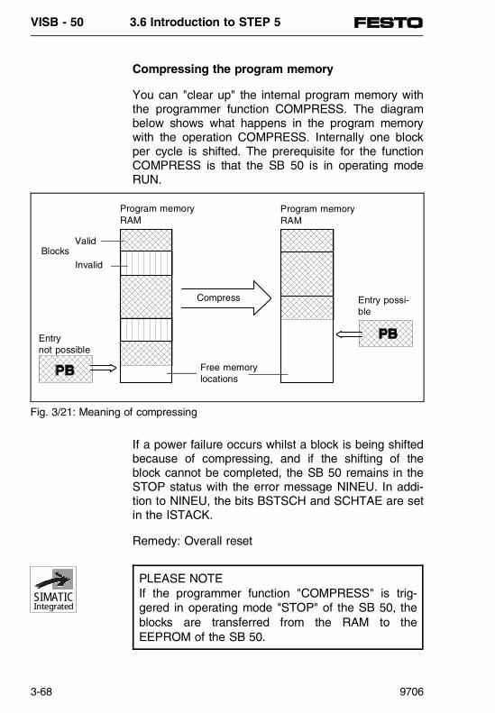
Compressing the program memory
You can "clear up" the internal program memory withthe programmer function COMPRESS. The diagrambelow shows what happens in the program memorywith the operation COMPRESS. Internally one blockper cycle is shifted. The prerequisite for the functionCOMPRESS is that the SB 50 is in operating modeRUN.
If a power failure occurs whilst a block is being shiftedbecause of compressing, and if the shifting of theblock cannot be completed, the SB 50 remains in theSTOP status with the error message NINEU. In addi-tion to NINEU, the bits BSTSCH and SCHTAE are setin the ISTACK.
Remedy: Overall reset
PLEASE NOTEIf the programmer function "COMPRESS" is trig-gered in operating mode "STOP" of the SB 50, theblocks are transferred from the RAM to theEEPROM of the SB 50.
Entrynot possible
ValidBlocks
Invalid
Program memoryRAM
Program memoryRAM
Compress Entry possi-ble
Free memorylocations
Fig. 3/21: Meaning of compressing
SIMATICIntegrated
VISB - 50 3.6 Introduction to STEP 5
3-68 9706

Representing numbers
STEP 5 gives you the possibility of working with num-bers in five different representations:• Decimal numbers from - 32768 to + 32767 (KF)• Hexadecimal numbers from 0000 to FFFF (KH)• BCD-numbers (4 tetrads) from 0000 to 9999• Bit pattern (KM)• Constant byte as two-byte representation (KY)
0... 55 per byte
VISB - 50 3.6 Introduction to STEP 5
9706 3-69

VISB - 50 3.6 Introduction to STEP 5
3-70 9706

3.7 STEP 5 OPERATIONS
PN
350
647
VISB - 50 3.7 STEP 5 operations
9706 3-71
Contents
3.7 STEP 5 OPERATIONS Basic operations.............................................3-74 Linking operations ............................................3-75 Memory operations...........................................3-75 Load operations................................................3-76 Transfer operations ..........................................3-78 Time operations................................................3-79 Counting operations .........................................3-79 Arithmetical operations .....................................3-79 Comparison operations ....................................3-80 Block access operations...................................3-81 Jump-back functions.........................................3-81 Zero operations ................................................3-81 Stop operations ................................................3-81 Picture structure operations .............................3-82 Supplementary operations ............................3-83 Linking operations ............................................3-84 Bit and memory operations ..............................3-85 Timing and counting operations .......................3-86 Load and transfer operations ...........................3-87 Jump operations ...............................................3-88 Other operations...............................................3-89 System operations............................................3-90 Evaluating CC 0 and CC 1...............................3-91
VISB - 50 3.7 STEP 5 operations
3-72 9706
3.7 STEP 5 OPERATIONS
The programming language STEP 5 distinguishes be-tween three types of operations:• Basic operations
Basic operations include functions which can beperformed in organization, program, step and func-tion blocks. Except for addition (+F), subtraction (-F) and the organizational operations, they can beinput and output in all three programming lan-guages (STL, CSF and LDR).
• Supplementary operationsSupplementary operations contain complex func-tions such as substitution instructions, test func-tions, shift and conversion operations. They canonly be input and output in the programming lan-guage STL.
• System operations System operations have direct access to the oper-ating system. Only an experienced programmershould use them. The system operations can onlybe input and output in the STL programming lan-guage.
VISB - 50 3.7 STEP 5 operations
9706 3-73

Basic operations
The scope of basic operations consists of the follow-ing categories of instructions:
- Linking operations- Memory operations- Loading and transferring- Timing operations- Counting operations- Arithmetical functions- Comparison operations- Block access operations- Other operations
The scope of basic operations can be used in allblocks (OB/PB/FB/SB). The basic operations arelisted and described in the following table:
VISB - 50 3.7 STEP 5 operations
3-74 9706

Oper-ation(STL)
Permittedoperands
RLO*
1 2 3
Processtime in
µs
Function description
Link operationsA I,Q N J N 3...5 AND link: interrogate for
signal status "1"F N J N 3...5T N J N 6...10C N J N 3...6
AN I,Q N J N 3...5 AND link: interrogate forsignal status "0"F N J N 8...5
T N J N 6...10C N J N 3...6
O I,Q N J N 3...5 OR link: interrogate for signal status "1"F N J N 3...5
T N J N 6...10C N J N 3...6
ON I,Q N J N 3...5 OR link: interrogate forsignal status "0"F N J N 3...5
T N J N 6...10C N J N 3...6
O N J N 2...5 OR link of AND functionsA( N J N 4...8 AND link of bracket expressions
(6 bracket levels)O( N J N 4...8 OR link of bracket expressions
(6 bracket levels)) N J N 4...10 Brackets closed (conclusion of a
bracket expression)Memory operations
S I,Q J N J 5...8 Set the operand at value "1"F J N J 5...8
R I,Q J N J 5...8 Set the operand at value "0"F J N J 5...8
= I,Q J N J 4...7 Value of the RLO is assigned tothe operandF J N J 4...7
* 1 RLO dependent? 2 RLO affected? 3 RLO reloaded?
Table 3/14: Link operations / memory operations
VISB - 50 3.7 STEP 5 operations
9706 3-75

Oper-ation(STL)
Permittedoperands
RLO*
1 2 3
Processtime in
µs
Function description
Load operations
L IB N N N 11 Load input byte of PII into ACCU1
L QB N N N 11 Load output byte of PIQ into ACCU1
L IW N N N 15 Load an input word of PII intoACCU1:Byte n → ACCU1 (bits 8...15)Byte n+1 → ACCU1 (bits 0...7)
L QW N N N 15 Load an output word of PIQ intoACCU 1:Byte n → ACCU1 (bits 8...15)Byte n+1 → ACCU1 (bits 0...7)
L PY0...127 N N N 39 Only permitted in OB13.Load an input byte of the digital/analogue entries from alarm PIIinto ACCU1
L PW0...127 N N N 42 Only permitted in OB13.Load an input word of the digital/analogue entries from alarm PIIinto ACCU1
L FY N N N 11 Load a flag byte into ACCU1L FW N N N 15 Load a flag word into ACCU1:
Byte n → ACCU1 (bits 8...15)Byte n+1 → ACCU1 (bits 0...7)
L DL N N N 33 Load left byte of a data wordof current data block intoACCU1
L DR N N N 35 Load right byte of a data word ofcurrent data block into ACCU1
L DW N N N 35 Load a data word of the currentdata block into ACCU1
* 1 RLO dependent? 2 RLO affected? 3 RLO reloaded?
Table 3/15: Load operations
VISB - 50 3.7 STEP 5 operations
3-76 9706

Oper-ation(STL)
Permittedoperands
RLO*
1 2 3
Processtime in
µs
Function description
Load operations (continued)L KB N N N 5 Load a constant (1-byte number)
into ACCU1L KS N N N 5 Load a constant (2-characters in
ASCII format) into ACCU1L KF N N N 5 Load a constant (fixed point
number) into ACCU1L KH N N N 5 Load a constant (hexa-code)
into ACCU1L KM N N N 5 Load a constant (bit pattern)
into ACCU1L KY N N N 5 Load a constant (2-byte number)
into ACCU1L KT N N N 5 Load a constant (time value)
into ACCU1 (BCD)L KC N N N 5 Load a constant (counter value)
into ACCU1 (BCD)L T,C N N N 14 Load a timer or counter value
(binary coded) into ACCU1LC T N N N 58 Load timer or counter value (BCD)
into ACCU1C N N N 59
* 1 RLO dependent? 2 RLO affected? 3 RLO reloaded?
Table 3/16: Load operations
VISB - 50 3.7 STEP 5 operations
9706 3-77

Oper-ation(STL)
Permittedoperands
RLO*
1 2 3
Processtime in
µs
Function description
Transfer operationT IB N N N 5 Transfer contents of ACCU1 to
an input byte (into PII)T QB N N N 5 Transfer contents of ACCU1 to
an output byte (into PIQ)T IW N N N 12 Transfer contents of ACCU1 to
an input word (into PII):ACCU1 (bits 8...15) → byte n;ACCU2 (bits 0...7) → byte n+1
T QW N N N 12 Transfer contents of ACCU1 toan output word (into PIQ):ACCU1 (bits 8...15) → byte n;ACCU2 (bits 0...7) → byte n+1
T PY0...127 N N N 41 Only permitted in OB13.Transfer contents of ACCU1 intoalarm PIQ with regard to PIQ
T PW0...127 N N N 45 Only permitted in OB13.Transfer contents of ACCU1 intoalarm PIQ with regard to PIQ
T FY N N N 5 Transfer contents of ACCU1 to a flag byte
T FW N N N 12 Transfer contents of ACCU1 to a flag word
T DL N N N 25 Transfer contents of ACCU1 to a data word (right byte)
T DR N N N 26 Transfer contents of ACCU1 toa data word (left byte)
T DW N N N 34 Transfer ACCU1 to a data word
* 1 RLO dependent? 2 RLO affected? 3 RLO reloaded?
Table 3/17: Transfer operations
VISB - 50 3.7 STEP 5 operations
3-78 9706

Oper-ation(STL)
Permittedoperands
RLO*
1 2 3
Processtime in
µs
Function description
Time operationsSP T J N J 64 Start a time (stored in ACCU1)
as impulseSE T J N J 64 Start a time (stored in ACCU1)
as extended impulseSD T J N J 65 Start a time (stored in ACCU1)
with switch-on delaySS T J N J 65 Start a time (stored in ACCU1)
storing with switch-on delaySF T J N J 64 Start a time (stored in ACCU1)
storing with switch-off delayR T J N J 21
Counter operationsCU C J N J 35 Counter counts 1 forwardsCD C J N J 40 Counter counts 1 backwardsS C J N J 62 Set a counterR C J N J 17 Reset a counter
Arithmetical functions+F N N N 19 Add two fixed point numbers:
ACCU1 + ACCU2. Result can beevaluated with CC 1/CC 0/O V
-F N N N 22 Subtract two fixed point numbers:ACCU2 - ACCU1. Result can beevaluated with CC 1/CC 0/O V
* 1 RLO dependent? 2 RLO affected? 3 RLO reloaded?
Table 3/18: Time/counter operations and arithmetical functions
VISB - 50 3.7 STEP 5 operations
9706 3-79
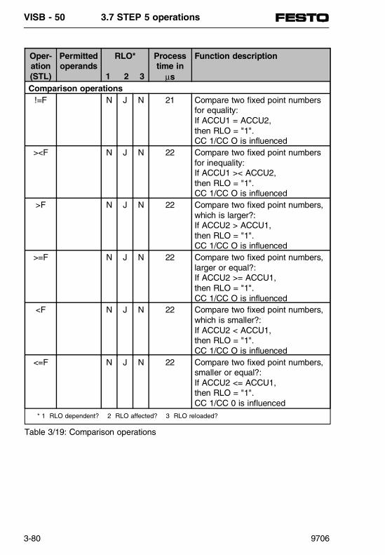
* 1 RLO dependent? 2 RLO affected? 3 RLO reloaded?
Oper-ation(STL)
Permittedoperands
RLO*
1 2 3
Processtime in
µs
Function description
Comparison operations!=F N J N 21 Compare two fixed point numbers
for equality:If ACCU1 = ACCU2, then RLO = "1". CC 1/CC O is influenced
><F N J N 22 Compare two fixed point numbersfor inequality:If ACCU1 >< ACCU2, then RLO = "1". CC 1/CC O is influenced
>F N J N 22 Compare two fixed point numbers,which is larger?:If ACCU2 > ACCU1, then RLO = "1". CC 1/CC O is influenced
>=F N J N 22 Compare two fixed point numbers,larger or equal?:If ACCU2 >= ACCU1, then RLO = "1". CC 1/CC O is influenced
<F N J N 22 Compare two fixed point numbers,which is smaller?:If ACCU2 < ACCU1, then RLO = "1". CC 1/CC O is influenced
<=F N J N 22 Compare two fixed point numbers,smaller or equal?:If ACCU2 <= ACCU1, then RLO = "1". CC 1/CC 0 is influenced
Table 3/19: Comparison operations
VISB - 50 3.7 STEP 5 operations
3-80 9706
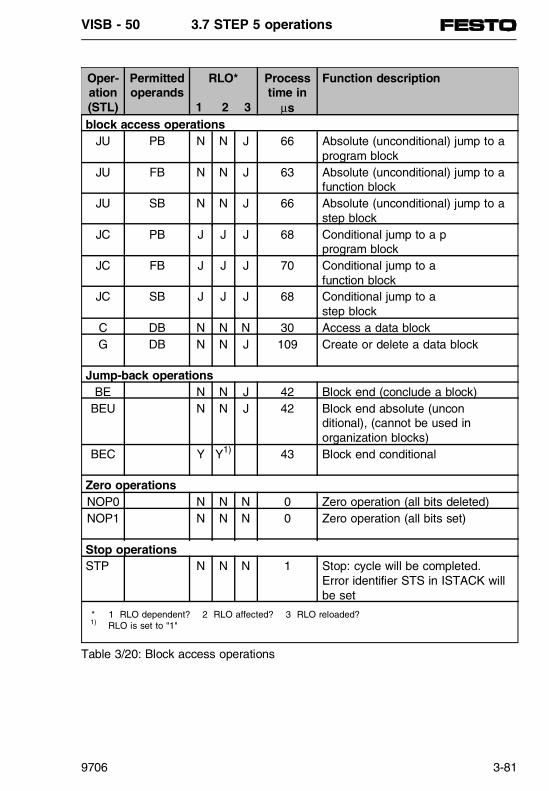
Oper-ation(STL)
Permittedoperands
RLO*
1 2 3
Processtime in
µs
Function description
block access operationsJU PB N N J 66 Absolute (unconditional) jump to a
program blockJU FB N N J 63 Absolute (unconditional) jump to a
function blockJU SB N N J 66 Absolute (unconditional) jump to a
step blockJC PB J J J 68 Conditional jump to a p
program blockJC FB J J J 70 Conditional jump to a
function blockJC SB J J J 68 Conditional jump to a
step blockC DB N N N 30 Access a data blockG DB N N J 109 Create or delete a data block
Jump-back operationsBE N N J 42 Block end (conclude a block)
BEU N N J 42 Block end absolute (uncon ditional), (cannot be used inorganization blocks)
BEC Y Y1) 43 Block end conditional
Zero operationsNOP0 N N N 0 Zero operation (all bits deleted)NOP1 N N N 0 Zero operation (all bits set)
Stop operationsSTP N N N 1 Stop: cycle will be completed.
Error identifier STS in ISTACK willbe set
* 1 RLO dependent? 2 RLO affected? 3 RLO reloaded? 1) RLO is set to "1"
Table 3/20: Block access operations
VISB - 50 3.7 STEP 5 operations
9706 3-81

Oper-ation(STL)
Permittedoperands
RLO*
1 2 3
Processtime in
µs
Function description
Picture structure operationsBLD130
N N N 0 Picture structure command for theprogrammer: Create an empty line withCarriage Return
BLD131
N N N 0 Picture structure command for theprogrammer: Switch to statement list (STL)
BLD132
N N N 0 Picture structure command for theprogrammer: Switch to function chart (CSF)
BLD133
N N N 0 Picture structure command for theprogrammer: Switch to ladder diagram (LDR)
BLD255
N N N 0 Picture structure command for theprogrammer: End segment (network)
* 1 RLO dependent? 2 RLO affected? 3 RLO reloaded?
Table 3/21: Picture structure operations
VISB - 50 3.7 STEP 5 operations
3-82 9706

Supplementary operations
Basic operations can be programmed in all blocks. Bymeans of the "supplementary operations", the scopeof operations can be extended. However, the follow-ing limitations apply to these operations:• They can only be programmed in function blocks.• They can only be represented in STL.
The supplementary operations consist of the followingcategories of instructions:- Substitution operations- Conversion operations- Shift operations - jump operations- Block/release alarm- Decrement/increment- Processing operation - system operations
Supplementary operations are described in the follow-ing tables.
VISB - 50 3.7 STEP 5 operations
9706 3-83
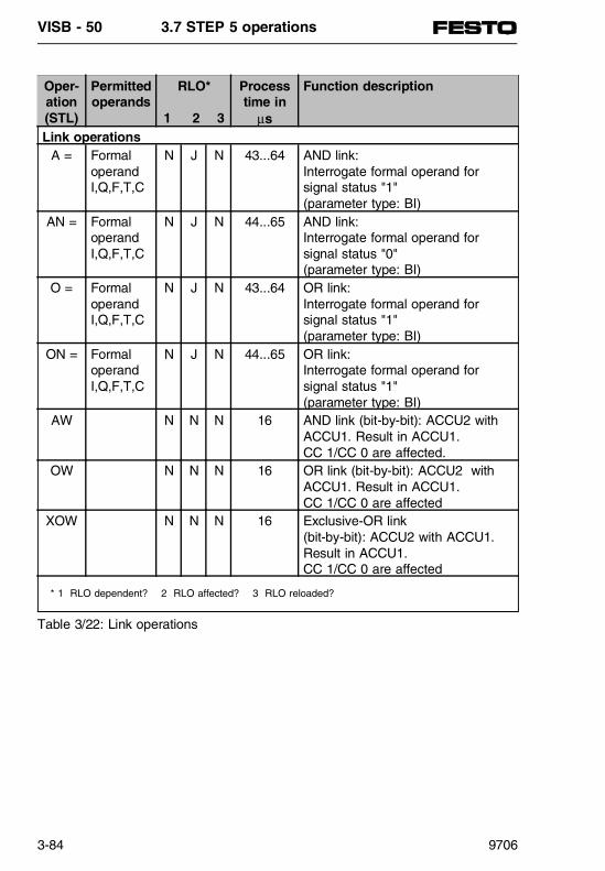
Oper-ation(STL)
Permittedoperands
RLO*
1 2 3
Processtime in
µs
Function description
Link operationsA = Formal
operandI,Q,F,T,C
N J N 43...64 AND link:Interrogate formal operand forsignal status "1"(parameter type: BI)
AN = FormaloperandI,Q,F,T,C
N J N 44...65 AND link:Interrogate formal operand forsignal status "0"(parameter type: BI)
O = Formaloperand I,Q,F,T,C
N J N 43...64 OR link:Interrogate formal operand forsignal status "1"(parameter type: BI)
ON = FormaloperandI,Q,F,T,C
N J N 44...65 OR link:Interrogate formal operand forsignal status "1"(parameter type: BI)
AW N N N 16 AND link (bit-by-bit): ACCU2 withACCU1. Result in ACCU1. CC 1/CC 0 are affected.
OW N N N 16 OR link (bit-by-bit): ACCU2 withACCU1. Result in ACCU1. CC 1/CC 0 are affected
XOW N N N 16 Exclusive-OR link(bit-by-bit): ACCU2 with ACCU1.Result in ACCU1. CC 1/CC 0 are affected
* 1 RLO dependent? 2 RLO affected? 3 RLO reloaded?
Table 3/22: Link operations
VISB - 50 3.7 STEP 5 operations
3-84 9706

Oper-ation(STL)
Permittedoperands
RLO*
1 2 3
Processtime in
µs
Function description
Bit operationsTB T,C N J N 5 Check bit of timer or counter word
for signal status "1"TB D N J N 32 Check bit of data word for
signal status "1"TB RS N J N 5 Check bit of data word in range of
system data for signal status "1"TBN T,C N J N 5 Check bit of timer or counter word
for signal status "0"TBN D N J N 33 Check bit of data word for
signal status "0"TBN RS N J N 5 Check bit of data word in range of
system data for signal status "0"SU T,C N N J 6 Set bit of a timer or counter
word unconditionallySU D N N J 34 Set bit of a data word
unconditionallyRU T,C N N J 6 Reset bit of a timer or counter
word unconditionallyRU D N N J 34 Reset bit of a data word
unconditionallyMemory operations
S = Formaloperand I,Q,F
J N J 69...79 Set a formal operand(with RLO = "1")(parameter type: BI)
RB = FormaloperandI,Q,F
J N J 70...81 Reset a formal operand(with RLO = "1")(parameter type: BI)
RD = FormaloperandT,C
J N J 56...60 Reset a formal operand (digital)(with RLO = "1")
= = FormaloperandI,Q,F
J N J 67...78 The value of the RLO is assignedto the status of the formal operand(parameter type: BI)
* 1 RLO abhängig? 2 RLO beeinflussend? 3 RLO begrenzend?
Table 3/23: Bit and memory operations
VISB - 50 3.7 STEP 5 operations
9706 3-85

Oper-ation(STL)
Permittedoperands
RLO*
1 2 3
Processtime in
µs
Function description
Timer and counter operationsFR T J↑ N J 20 Release timer/counter for new start.
If RLO = 1, with- "FR T" the timer will be started- "FR C" the counter will be set, counted forwards or backwards.
C J↑ N J 16
FR = Formaloperand T
J↑ N J 70 Release formal operand(timer/counter) for new start.If RLO = 1, with- "FR T" the timer will be started- "FR C" the counter will be set, counted forwards or backwards.
Formaloperand C
J↑ N J 66
SP= Formaloperand T
J↑ N J 114 Start a timer (formal operand) asimpulse. Value is stored in ACCU1.
SD= Formaloperand T
J↑ N J 116 Start a timer (formal operand) withswitch-on delay. Value is storedin ACCU1.
SEC= Formaloperand T
J↑ N J 114 Start a timer (formal operand) asextended impulse with the valuestored in ACCU1, or set a counter(formal operand) with the followingspecified counter value.
Formaloperand C
J↑ N J 112
SSU= Formaloperand T
J↑ N J 116 Start a timer (formal operand) asstored switch-on delay with thevalue stored in ACCU1, orincrement a counter (formaloperand).
Formaloperand C
J↑ N J 68
SFD= Formaloperand T
J↓ N J 114 Start a timer (formal operand) asswitch-off delay with the valuestored in ACCU1, or decrement acounter (formal operand).Formal
operand CJ↑ N J 98
* 1 RLO dependent? 2 RLO affected? 3 RLO reloaded?
Table 3/24: Timer and counter operations
VISB - 50 3.7 STEP 5 operations
3-86 9706

Oper-ation(STL)
Permittedoperands
RLO*
1 2 3
Processtime in
µs
Function description
Load and transfer operationsL = Formal
operand I,Q,F,T,C
N N N 40...66 Load the value of the formaloperand into the ACCU1.Parameter type: BY, W;Further actual operands: DL, DR, DW
L RS N N N 15 Load a word from the rangesystem data into the ACCU1.
LD = Formaloperand T,C
N N N 86 Load the value of the formaloperand in BCD code intothe ACCU1.
LW = Formaloperand
N N N 34 Load the bit pattern of a formaloperand into the ACCU1.(parameter form D; parameter typeKF, KH, KM, KY, KC, KT, KZ)
T= Formaloperand I,Q,F
N N N 34...64 Transfer the contents of ACCU1 tothe formal operand (parameter type: BY, W); additional actual operands:DR, DL, DW
Conversion operationsCFW N N N 4 Form the complement of 1 of
ACCU1CSW N N N 19 Form the complement of 2 of
ACCU1. CC 1/CC 0 and OV areaffected.
Shift operationsSLW Parameter
n=0...15N N N 12 + n×8 Shift contents of ACCU1 to the left
by the value specified in theparameter. Free positions will befilled with "0". CC 1/CC 0 areaffected.
SRW Parameter n=0...15
N N N 12 + n×8 Shift contents of ACCU1 to theright by the value specified in theparameter. Free positions will befilled with "0". CC 1/CC 0 are affected.
* 1 RLO dependent? 2 RLO affected? 3 RLO reloaded?
Table 3/25: Load and transfer, conversion and shift operations
VISB - 50 3.7 STEP 5 operations
9706 3-87

Oper-ation(STL)
Permittedoperands
RLO*
1 2 3
Processtime in
µs
Function description
Jump operationsJU= Symbol
addr. max.4 char.
N N N 5 Jump absolute (unconditional)to jump address
JC= Symboladdr. max.4 char.
Y Y Y1) 7 Conditional jump to symbol address (If RLO = "0", RLO "1" will be set)
JZ= Symboladdr. max.4 char.
N N N 9 Jump if zero: only made if CC1=0 and CC0=0. The RLO is not modified.
JN= Symboladdr. max.4 char.
N N N 12 Jump if not zero: only made if CC >< 0. The RLO is not modified.
JP= Symboladdr.max.4 char.
N N N 9 Jump if plus sign: only made if CC 1=1 and CC 0=0. The RLO is not modified.
JM= Symboladdr. max.4 char.
N N N 9 Jump if minus sign: only made if CC 1=0 and CC 0=1. The RLO is not modified.
JO= Symboladdr. max.4 char.
N N N 7 Jump if "overflow": only made if display OVERFLOW is set. The RLO is not modified.
* 1 RLO dependent? 2 RLO affected? 3 RLO reloaded? 1) RLO will be set to "1"
Table 3/26: Jump operations
VISB - 50 3.7 STEP 5 operations
3-88 9706
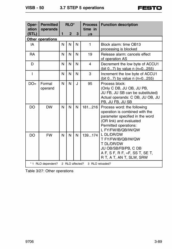
Oper-ation(STL)
Permittedoperands
RLO*
1 2 3
Processtime in
µs
Function description
Other operationsIA N N N 1 Block alarm: time OB13
processing is blockedRA N N N 19 Release alarm: cancels effect
of operation ASD N N N 4 Decrement the low byte of ACCU1
(bit 0...7) by value n (n=0...255)I N N N 3 Increment the low byte of ACCU1
(bit 0...7) by value n (n=0...255)DO= Formal
operandN N J 95 Process block:
(Only C DB, JU OB, JU PB, JU FB, JU SB can be substituted)Actual operands: C DB, JU OB, JUPB, JU FB, JU SB
DO DW N N N 181...216 Process word: the followingoperation is combined with theparameter specified in the word(OR link) and evaluatedPermitted operations:L FY/FW/IB/QB/IW/QWL DL/DR/DWT FY/FW/IB/QB/IW/QWT DL/DR/DWJU OB/SB/FB/PB, C DBA F, S F, R F, =F, SS T, SE T, R T, A T, AN T, SLW, SRW
DO FW N N N 139...174
* 1 RLO dependent? 2 RLO affected? 3 RLO reloaded?
Table 3/27: Other operations
VISB - 50 3.7 STEP 5 operations
9706 3-89

Oper-ation(STL)
Permittedoperands
RLO*
1 2 3
Processtime in
µs
Function description
Set operationsSU RS N N J 6 Set bit in range of
system data unconditionally RU RS N N J 6 Reset bit in range of
system data unconditionallyLoad and transfer operations
LIR N N N 50 Load register (0: ACCU1, 2: ACCU2) with contents of amemory word indirectly(addressed by ACCU1)
TIR N N N 50 Transfer register (0: ACCU1, 2: ACCU2) into memory wordindirectly (addressed by ACCU1)
TNB Parameter n=0...255
N N N 52 + n×16 Byte-by-byte block transfer (number of bytes 0...255)
T RS N N N 12 Transfer a word to the rangeof the system data.
Block access and jump back operationsJU OB N N J 61 Access organization block absolute.JC OB J J J Access organization block
conditionally.Arithmetical operationsADD BK N N N 10 Add byte constant to ACCU1ADD KF N N N 10 Add fixed point constant (word) to
ACCU1Other operationsSTS N N N 2 Stop command: program
processing is discontinuedimmediately after the command
TAK N N N 10 Swap the contents of ACCU1 and ACCU2
* 1 RLO dependent? 2 RLO affected? 3 RLO reloaded?
Table 3/28: System operations
VISB - 50 3.7 STEP 5 operations
3-90 9706

CC 1 CC 0 Arith-meticaloperations
Digital linkoperations
Com-parison operations
Shiftoperations
Conversion operations
0 0 Result= 0
Result= 0
ACCU2 = ACCU1
Shifted bit= 0
---
0 1 Result< 0
--- ACCU2 < ACCU1
--- Result< 0
1 0 Result> 0
Result>< 0
ACCU2 > ACCU1
Shifted bit= 1
Result> 0
Table 3/29: Evaluation of CC 1 and CC 0
VISB - 50 3.7 STEP 5 operations
9706 3-91

VISB - 50 3.7 STEP 5 operations
3-92 9706

3.8 INTEGRATED BLOCKS
PN
350
647
VISB - 50 3.8 Integrated blocks
9706 3-93

Contents
3.8 INTEGRATED BLOCKS DB1: parametrizing internal functions ..............3-95 Rules for parametrizing DB1............................3-97 Transferring the DB1 parameters.....................3-99 Parameter block ERT.....................................3-100 Localizing parametrizing errors ......................3-102 Parameter block SDP.....................................3-103 Parameter block TFB .....................................3-103 Parameter block SL1......................................3-103 DB1 parametrizing for reference....................3-104 Integrated function blocks ..........................3-105 Code converter: B4 -FB240- ..........................3-105 Code converter: 16 -FB241-...........................3-106 Multiplier: 16 -FB242- .....................................3-106 Divider: 16 -FB243- ........................................3-107 Analogue value adaption blocks ....................3-108 Reading the analogue value -FB250- ............3-108 Outputting the analogue value -FB251- .........3-110 Diagnosis SINEC L2-DP -FB230- ..................3-111 Diagnosis of local periphery -FB231-.............3-113 Integrated organization blocks ...................3-115 Cycle trigger -OB31-.......................................3-115 PID-control algorithm -OB251- .......................3-116 SB 50 to SINEC L1.......................................3-117 Parametrizing for data exchange ...................3-118 Coordinating the data exchange ....................3-121 Sending data ..................................................3-122 Structure of coordinating byte KBS................3-123 Receiving data................................................3-124 Structure of coordinating byte KBE................3-125 Special features..............................................3-126
VISB - 50 3.8 Integrated blocks
3-94 9706

3.8 INTEGRATED BLOCKS
DB1: parametrizing internal functions
The SB 50 has functions which you can set (parame-trize) according to your needs. These functions are asfollows:• Enable data exchange via SINEC L1• Modify access interval for time-controlled program
processing (OB13)• Set system characteristics• Determine address for parametrizing error code
You can parametrize these functions in data blockDB1.
Structure and presettings of DB1
To simplify parametrizing, a DB1 with preset values(default parameters) has already been fitted into theSB 50. If you load the default DB1 from the SB 50into the programmer after "Overall reset" and displaythis on the screen, it will be composed as follows:
"DB1" must stand in front of the parameter blocks,followed by at least one filling character (empty spaceor comma).
0: KC =,DB1 #SL1: SLN 1 SF DB2 ’;12: KC =, DW0 EF DB3 DW0 KB’;24: KC =,E MB100 KBS MB101 ’;36: KC =, PGN 1 ;# SDP: NT 12’;48: KC =,8 ; TFB: OB13 100 ; E’;60: KC =,ND ’
Fig. 3/22: DB1 with default parameters
SIMATICIntegrated
VISB - 50 3.8 Integrated blocks
9706 3-95
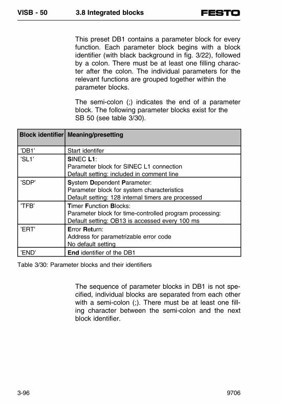
This preset DB1 contains a parameter block for everyfunction. Each parameter block begins with a blockidentifier (with black background in fig. 3/22), followedby a colon. There must be at least one filling charac-ter after the colon. The individual parameters for therelevant functions are grouped together within the parameter blocks.
The semi-colon (;) indicates the end of a parameterblock. The following parameter blocks exist for the SB 50 (see table 3/30).
The sequence of parameter blocks in DB1 is not spe-cified, individual blocks are separated from each otherwith a semi-colon (;). There must be at least one fill-ing character between the semi-colon and the nextblock identifier.
Block identifier Meaning/presetting
’DB1’ Start identifer’SL1’ SINEC L1:
Parameter block for SINEC L1 connection Default setting: included in comment line
’SDP’ System Dependent Parameter: Parameter block for system characteristicsDefault setting: 128 internal timers are processed
’TFB’ Timer Function Blocks: Parameter block for time-controlled program processing:Default setting: OB13 is accessed every 100 ms
’ERT’ Error Return: Address for parametrizable error codeNo default setting
’END’ End identifier of the DB1
Table 3/30: Parameter blocks and their identifiers
VISB - 50 3.8 Integrated blocks
3-96 9706

Rules for parametrizing the DB1
We have listed here all the rules which you must ob-serve if you wish to modify parameters or completewhole parameter blocks in DB1. It is essential thatthese rules be observed, as otherwise the SB 50 can-not "understand" what you have entered.• Start identifier "DB1"
The DB1 must begin with the entry "DB1". Thethree characters must not be separated from eachother by filling characters. After the start identifierthere must be at least one filling character.Empty spaces and commas are generally permit-ted as filling characters.
• After the start identifer together with filling charac-ter, there comes the block identifer of a parameterblock. The sequence of the parameter blocks inDB1 is optional. The block identifier marks a blockof parameters which belong together. The blockidentifer "SL1" stands e.g. for SINEC L1 parame-ter. There must be a colon (:) immediately after theblock identifier. If the colon is missing, the SB 50will jump over this block and issue an error mes-sage. There must be at least one filling characterafter the block identifier concluded with a colon.
• A parameter name followsParameter names are names for individual parame-ters within a parameter block. Within a block thefirst four characters of a parameter name must bedifferent from each other. There must be at leastone filling character after the parameter name.
• At least one argument belongs to each parametername. An argument is either a number or a STEP5 operand which you must enter. If several argu-ments belong to a parameter name, they must beseparated from each other by at least one fillingcharacter. At least one filling character must alsofollow the last argument.
VISB - 50 3.8 Integrated blocks
9706 3-97
• The end of the block must be marked by a semi-colon (;). There must be at least one filling charac-ter after the semi-colon. If you forget the semi-colon, there will be an error interpretation in theSB 50.
• Further parameter blocks can then follow. • The end identifier "END" must be entered at the
end of the last parameter block. This marks theend of the DB1. If you forget to enter this end iden-tifier, there will be an error in the SB 50.
• Comments can be entered in the DB1. Commentscan be inserted at any point where a filling charac-ter may also reside. The comment character is thelattice symbol (#). This must reside at the begin-ning and at the end of a comment. The text be-tween two comment characters must not containany further lattice symbol. At least one filling cha-racter must follow.
VISB - 50 3.8 Integrated blocks
3-98 9706

Transferring the DB1 parameters to the SB 50
In contrast to the other data blocks, the DB1 is onlyprocessed once, during a new start of the SB 50. Thishas been done in order to equip the DB1 for certainvery special functions.
Such a special function is the parametrizing of the SB 50 with the aid of the DB1. Parametrizing meansthat you enter in data block DB1 the parameters forthe internal functions with which your SB 50 is towork.
These entries in the DB1 are only transferred to theoperating system during a new start of the SB 50.Every modification in the DB1 must therefore be fol-lowed by a corresponding new start. This can be ac-complished by switching from
- POWER OFF ⇒ POWER ON or from - STOP ⇒ RUN
The SB 50 takes over the parameters of the DB1 andstores them in the system data range. In order tostore the parameters remanent in the EEPROM me-mory, the programmer function "Compress automationdevice" must be carried out in operating mode"STOP" (see chapter 3.6).
PLEASE NOTE The SB 50 remains in STOP if it detects a para-metrizing error during the start. The red LED willthen light up on the operating panel and an erroraddress of the DB1 will be shown in the ISTACK.
VISB - 50 3.8 Integrated blocks
9706 3-99

Parameter block ERT: Recognizing and eliminating parametrizing errors.
If there has been an error in parametrizing and if theSB 50 does not enter the RUN status, there are twopossibilities of recognizing parametrizing errors:- With the aid of a parametrizing error code
or- By means of the analysis function "ISTACK"
Both possibilities are described below.
Interrogate parametrizing error code
If you have specified a start address for the parame-trizing error code in parameter block "ERT:" of theDB1, then you can interrogate the cause of the errorand its location under this address.
The complete error code occupies 10 data words or20 flag bytes. In the following examples and tables weassume that the error code is stored in a data blockas from data word 0. The error code then occupiesDW0...DW9. In the operand range "Flags", this cor-responds to FY0...FY18.
VISB - 50 3.8 Integrated blocks
3-100 9706

Example:
ERT: ERR DB3 DW0 ;You have specified the start address DB3 DW0 in theparameter block "ERT:" and the DB1 thus parame-trized has already been accepted by the automationdevice.You then continue parametrizing the DB1. After trans-ferring the modified DB1 parameters to the SB 50,you ascertain that the latter remains in STOP. Youassume the cause of the STOP to be a parametrizingerror. In order to find the error, you must output theDB3 on the programmer. The complete contents ofthe DB3 will appear on the screen; the data wordsDW0 to DW9 contain the parametrizing error code.
The diagram below shows what your screen mightlook like. Directly after the screen display you will finda complete list of parametrizing error codes and theirmeaning.
0: KH= 0603 1: KH= 0000 2: KH= 0000 3: KH= 0000 4: KH= 0000 5: KH= 0000 6: KH= 0000 7: KH= 0000 8: KH= 0000 9: KH= 000010: KH= 0000
Fig. 3/23: Screen display with parametrizing errors
VISB - 50 3.8 Integrated blocks
9706 3-101

Localizing parametrizing errors in the "ISTACK"
If, during the start, the SB 50 detects a parametrizingerror in the DB1, the SB 50 will remain in the STOPstatus and enter the error in the ISTACK. The ISTACK contains both the absolute (error) ad-dress and the relative (error) address. The STEP ad-dress counter (SAC) in the ISTACK then showseither:- The address containing the incorrect entry or- The position directly in front of the address contain-
ing the incorrect entry. These are byte addresses.
Error cause(Which error has occurred?)
DL DR Error location(In which parameter block hasthe error occurred?)
No error 00 00 Not definedStart or end identifier missing 01 01 Not definedNon concluded commentbefore END; semi-colon beforeEND missing.
02 02 Not defined
Block identifier syntax error 03 03 SL1: SINEC L1Argument syntax error 05 09 TFB: Timer function blockRange exceeded or notreached in an argument
06 11 SDP: System data parameter
Parameter combination notpermitted
07
Not defined 08Not defined 09DB does not exist 10Insufficient space in DB 11 99 ERT: Error Return
Table 3/31: Parametrizing error code and its meaning
VISB - 50 3.8 Integrated blocks
3-102 9706

Parameter block SDP: Determining the system characteristics in the DB1
In this parameter block you can set the number of the128 internal timers which are to be continually pro-cessed by the processor. (Parameter NT 128)
The parameter for the internal timers "NT" has beenset so that all 128 timers are processed continually.You can reduce the processing time required for thisby parametrizing only the number of internal timersthat you actually need.
Parameter block TFB: Set access interval "time-controlled program processing"
In this parameter block you can set the access inter-val of the time-controlled program processing. Thevalues 0...655350 ms are possible here, wherebysteps of 10 ms are specified (e.g. 110, 120, 130, etc.).Entering the value 100 means an access and pro-cessing of the OB13 at intervals of 100 ms.
Parameter block SL1: Data exchange via SINEC L1
In this parameter block you can specify the addressesof the data fields (transmitter and receiver) and theassigned coordination bytes. A detailed descriptioncan be found in the chapter " SINEC L1".
VISB - 50 3.8 Integrated blocks
9706 3-103

DB1 parametrizing for reference
Parameter Argument Meaning
Block identifier: SL1: SINEC L1SLNSFEFKBEKBSPGN
pDBx DWyDBx DWyFYyFYyp
Slave numberPosition of transmitterPosition of receiverPosition of coordination byte "Receive"Position of coordination byte "Transmit"PG bus number
p = 1...30 x = 2...255 y = 0...255 Default setting: commentBlock identifier: TFB: Timer Function blockOB13 p Interval (ms) during which the OB13 is
accessed and processedp = 0...655350 (in 10 ms steps) Default setting: 100 msBlock identifier: ERT: Store for error information of the DB1 evaluation
(10 errors needs 2 bytes)ERR FYy or
DBx DWyAddress for the parametrizing error code
x = 2...255 y = 0...255 No default settingBlock identifier: SDP: System Dependent ParameterNT p Number of timers which are processedp = 0...128 Default setting: 128
Table 3/32: Parameterizing of the DB1 for reference
VISB - 50 3.8 Integrated blocks
3-104 9706

Integrated function blocks
Some standard function blocks are integrated in theSB 50. These blocks can be accessed in the controlprogram with the commands "JU FB x" or "JC FB x" -x stands for the block number.
Code converter : B4 -FB240-
With this function block, a BCD number (4 tetrads)with sign can be converted into a fixed point binarynumber (16 bits). 2-tetrad numbers must be trans-ferred to 4-tetrad numbers before conversion.
If a tetrad is not in a BCD-defined range, the FB240will output the value "0". There is no error bit display.
Block no. FB240 FB241 FB242 FB243 FB250 FB251Block name COD:B4 COD:16 MUL:16 DIV:16 RLG:AE RLG:AAAccess length(in words)
5 6 7 10 10 9
Processsingtime (in ms)
< 0.8 < 1.0 < 0.9 ≤ 2.1 ≤ 2.4 ≤ 4.8
Diagnostic blocksBlock no. FB230 FB231Block name S_DIAG P_DIAGAccess length (in words)
4 4
Processingtime (in ms)
< 6.5 < 2
Table 3/33: Summary of the integrated function blocks
Parameter Meaning Type Assignment STLBCD BCD number I W 0...9999 :JU FB240
NAME :COD:B4BCD :SBCD :DUAL :
SBCD Sign of BCDnumber
I BI "1" for "-""0" for "+"
DUAL Fixed pointnumber (KF)
Q W 16 bits "0"or "1"
Table 3/34: Access and parametrizing of the FB240
VISB - 50 3.8 Integrated blocks
9706 3-105

Code converter : 16 -FB241-
With this function block, a fixed point binary number(16 bits) can be converted into a BCD number withthe sign taken into account. 8-bit binary numbersmust be transferred to 16-bit words before conversion.
Multiplier : 16 -FB242-
With this function block, two fixed point binary num-bers (16 bits) can be multiplied. The result is repre-sented by a fixed point number (32 bits). In addition,the result is interrogated for zero. 8-bit numbers mustbe transferred to 16-bit words before multiplication.
Parameter Meaning Type Assignment STLDUAL Binary number I W - 32768...+ 32767 :JU FB241
NAME :COD:16DUAL :SBCD :BCD2 :BCD1 :
SBCD Sign of BCDnumber
Q BI "1" for "-""0" for "+"
BCD2 BCD number4th & 5th tetrads
Q BY 2 tetrads
BCD1 BCD number tetrads 0...3
Q W 4 tetrads
Table 3/35: Access and parametrizing the FB241
Parameter Meaning Type Assignment STLZ1 Multiplier I W - 32768...+ 32767 :JU FB242
NAME :MUL:16Z1 :Z2 :Z3=0 :Z32 :Z31 :
Z2 Multiplicand I W - 32768...+ 32767Z3=0 Interrogate
for zeroI BI "1" if the result
is zeroZ32 Result high word Q W 16 bitsZ31 Result low word Q W 16 bits
Table 3/36: Access and parametrizing the FB242
VISB - 50 3.8 Integrated blocks
3-106 9706

Divider : 16 -FB243-
With this function block, two fixed point binary num-bers (16 bits) can be divided. The result (quotient andrest) is represented by two fixed point binary numbers(16 bits each).
In addition, the result and the divisor are interrogatedfor zero. 8-bit numbers must be transferred to 16-bitwords before division.
Parameter Meaning Type Assignment STLZ1 Dividend I W - 32768...+ 32767 :JU FB243
NAME :DIV:16Z1 :Z2 :OV :FEH :Z3=0 :Z4=0 :Z3 :Z4 :
Z2 Divisor I W - 32768...+ 32767OV Overrun display Q BI "1" if overrunFEH Error Q BI "1" if division by
zeroZ3=0 Interrogate for
zeroQ BI "1":quotient is
zeroZ4=0 Interrog. for zero Q BI "1":rest is zeroZ3 Quotient Q W 16 bitsZ4 Rest Q W 16 bits
Table 3/37: Access and parametrizing the FB243
VISB - 50 3.8 Integrated blocks
9706 3-107
Analogue value adapter blocks -FB250 and FB251-
The FB250 reads an analogue value of an analogueinput module. It then supplies a value XA at the out-put in a (standard) range specified by the user.
With the FB251, analogue values can be output onanalogue output blocks. Values are thereby trans-ferred from the range between the parameters lowerlimit "UGR" and upper limit "OGR" to the nominalrange of the appropriate block.
PLEASE NOTEThe analogue value adapter blocks FB250 andFB251 can be used with the SF 50 as stand-ardizing blocks for analogue blocks of the decentralperiphery.
Read and standardize analogue value -FB250-
This function block reads an analogue value of ananalogue input block and supplies a value XA at theoutput in a (standardized) range specified by the user.
The type of analogue value representation of theblock (channel type) must be specified in parameterKNKT (see table 3/38).
With the parameters upper limit OGR and lower limitUGR, the user can determine the desired range.
VISB - 50 3.8 Integrated blocks
3-108 9706
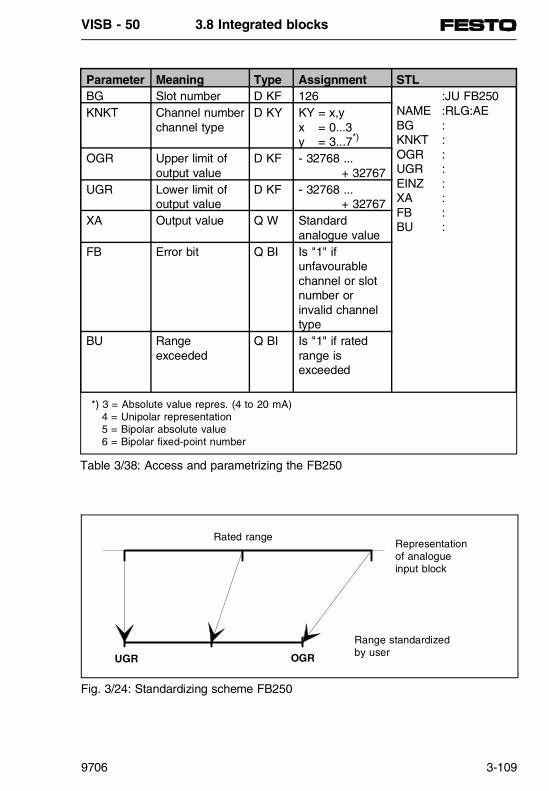
Parameter Meaning Type Assignment STLBG Slot number D KF 126 :JU FB250
NAME :RLG:AEBG :KNKT :OGR :UGR :EINZ :XA :FB :BU :
KNKT Channel numberchannel type
D KY KY = x,yx = 0...3y = 3...7*)
OGR Upper limit ofoutput value
D KF - 32768 ... + 32767
UGR Lower limit ofoutput value
D KF - 32768 ... + 32767
XA Output value Q W Standard analogue value
FB Error bit Q BI Is "1" if unfavourable channel or slotnumber orinvalid channeltype
BU Rangeexceeded
Q BI Is "1" if ratedrange isexceeded
*) 3 = Absolute value repres. (4 to 20 mA) 4 = Unipolar representation 5 = Bipolar absolute value 6 = Bipolar fixed-point number
Table 3/38: Access and parametrizing the FB250
Rated range
UGR OGR
Representation of analogueinput block
Range standardizedby user
Fig. 3/24: Standardizing scheme FB250
VISB - 50 3.8 Integrated blocks
9706 3-109
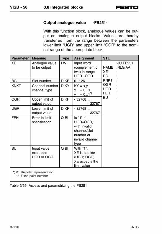
Output analogue value -FB251-
With this function block, analogue values can be out-put on analogue output blocks. Values are therebytransferred from the range between the parameterslower limit "UGR" and upper limit "OGR" to the nomi-nal range of the appropriate block.
*) 0: Unipolar representation 1: Fixed-point number
Parameter Meaning Type Assignment STLXE Analogue value
to be outputI W Input word
(complement oftwo) in rangeUGR...OGR
:JU FB251NAME :RLG:AAXE :BG :KNKT :OGR :UGR :FEH :BU :
BG Slot number D KF 0...126KNKT Channel number
channel typeD KY KY = x,y
x = 0...1y = 0...1*)
OGR Upper limit ofoutput value
D KF - 32768 ... + 32767
UGR Lower limit ofoutput value
D KF - 32768 ... + 32767
FEH Error in limitspecification
Q BI Is "1" ifUGR=OGR,with invalidchannel/slotnumber orinvalid channeltype
BU Input valueexceededUGR or OGR
Q BI With "1", XE is outside(UGR; OGR) XE accepts thelimit value
Table 3/39: Access and parametrizing the FB251
VISB - 50 3.8 Integrated blocks
3-110 9706
Diagnostic evaluation of local and decentral periphery
Diagnostic evaluation SINEC L2-DP: S_DIAG -FB230-
The function block S_DIAG reads the diagnostic dataof the parametrized SINEC L2-DP Slave station andstores it in the parametrized data block S_DIAG. Upto 34 bytes of diagnostic data (as per PROFIBUS-DP- DIN 19245 part 3) are stored in the data block des-ignated by the transfer parameter, beginning with thedata word also specified by transfer parameter.
PLEASE NOTE This function block can only be used with the SB 50 with field bus extension, i.e. the SF 50.
The data block intended for receiving the diagnosticdata must be created in sufficient length before thefunction block S_DIAG is accessed. The minimumlength of the data block should be determined by themaximum length of the diagnostic information of 17data words (34 bytes). It is therefore sensible tocheck the existence of a diagnostic message by inter-rogating the station diagnostic bits before accessingthe function block 230.
SIMATICIntegrated
VISB - 50 3.8 Integrated blocks
9706 3-111
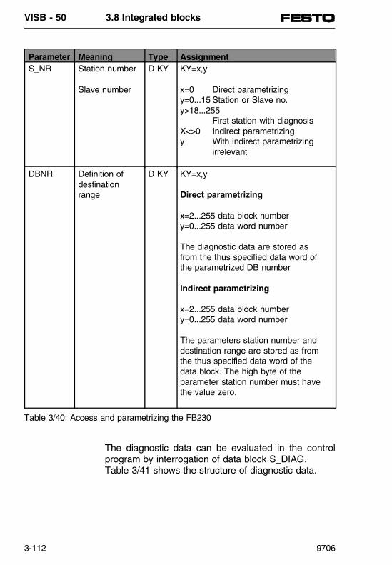
The diagnostic data can be evaluated in the controlprogram by interrogation of data block S_DIAG. Table 3/41 shows the structure of diagnostic data.
Parameter Meaning Type AssignmentS_NR Station number
Slave number
D KY KY=x,y
x=0 Direct parametrizingy=0...15 Station or Slave no.y>18...255
First station with diagnosisX<>0 Indirect parametrizingy With indirect parametrizing
irrelevant
DBNR Definition ofdestinationrange
D KY KY=x,y
Direct parametrizing
x=2...255 data block numbery=0...255 data word number
The diagnostic data are stored asfrom the thus specified data word ofthe parametrized DB number
Indirect parametrizing
x=2...255 data block numbery=0...255 data word number
The parameters station number anddestination range are stored as fromthe thus specified data word of thedata block. The high byte of theparameter station number must havethe value zero.
Table 3/40: Access and parametrizing the FB230
VISB - 50 3.8 Integrated blocks
3-112 9706

Example
:A I126.3 Fourth Slave station on SF 50 is faulty
:JU FB230 Access diagnostic blockS_DIAG
Name :S_DIAG S_NR : KY 0.3 Direct parametrizing
Interrogation of fourth Slave DBNR : KY 2.0 Store diagnostic data in
DB2, as from DW0
Diagnostic block of local periphery:P_DIAG -FB231-
With this function block, a short circuit diagnosis canbe made of the outputs (local periphery) of the valveterminals with output blocks. An FW (0...254) or DW(0...254) serves as transfer parameter in which thebyte number of the first short-circuited output in thelow byte, and the bit number of the first short-circuitedoutput in the high byte of the input parameter isstored.
SIMATICIntegrated
DWn Diagnosis address (DLn) Diagnosis address + 1 (DRn)0 Number of Slave station which
supplies the diagnosisNumber of subsequentdiagnostic bytes
1 Station status 1 Station status 22 Station status 3 Master address3 Depending on manufacturer information4 Header Code-specific diagnostics5 Code-specific diagnostics Code-specific diagnostics
6 ... 8 Code-specific diagnostics Code-specific diagnostics
Table 3/41: Structure of diagnostic data (DIN E19245, part 3)
VISB - 50 3.8 Integrated blocks
9706 3-113

PLEASE NOTE Function block FB231 can only be used with avalve terminal with output blocks. This should becalled at the end of cyclic program execution(OB1).
Evaluation can only be made if the short-circuit is dis-played with I7.2 = "1" in the diagnostic byte of thelocal periphery (IB7). A short-circuited output must bereset by the user when the short circuit has beeneliminated.
Example
:A I7.2 Short circuit of an output:JU FB231 Access block P_DIAG
Name :P_DIAG QUIT : F202.0 Reset outputA_NR : FW200 Transfer output
:L KY3.2 Mask for output Q2.3 :L FW200:!=F:A I7.2:= F21.3 Error message, short circuit
Q2.3
Parameter Meaning Type AssignmentQUIT Reset the
short-circuitedoutput
I BI The detected short-circuited output isreset if the input parameter QUIT hassignal status "1".
A_NR Short-circuitedoutput
Q W In this word the first short-circuitedoutput of the local periphery of anoutput block is transferred to thecontrol program.Data are stored in format KYKY = x,yx = 0...7 bit number of outputy = 0...7 byte number of output
Table 3/42: Access and parametrizing the FB231
VISB - 50 3.8 Integrated blocks
3-114 9706

Integrated organization blocks
Cycle trigger OB31
By means of a "cycle monitor", the time course of cy-clic program processing can be controlled. If programprocessing lasts longer than the cycle monitoring timeset of 300 ms, then the SB 50 will enter the STOPstatus. This can occur when:- The control program is too long- An endless loop is programmedBy accessing the OB31, the cycle monitor can be trig-gered again at any point in the control program, i.e.the cycle monitoring time is activated again.
Access- Condition: on the programmer SYSTEM
COMMANDS "YES"- Enter at any point in the control program
JU OB31
Programming An instruction within the OB31 is sufficent, e.g. "BE",to activate the re-triggering. Further instructions arepossible.
VISB - 50 3.8 Integrated modules
9706 3-115

PID control algorithm OB251
A PID control algorithm is integrated in the operatingsystem of the SB 50. With the aid of the organizationblock OB251, you can use this for your own pur-poses.
Before accessing the OB251, you must open a datablock (regulator DB) which contains the control par-ameters and other control-specific data. The PID algo-rithm is accessed in a particular time pattern andforms the positioning variable. The more accuratelythe scanning time, the more accurately the regulatorcan fulfil its tasks. The control parameters specified inthe regulator DB must be adapted to the scanningtime.
You should always access the OB251 in the time OB(OB13). Time OBs can be set at access intervals of10 ms to 655350 ms. The maximum processing timeof the PID control algorithm is 1.7 ms.
The quasi-continuous regulator has been designed forcontrol paths such as occur, e.g. in process techno-logy as pressure, temperature or flow control devices.
(see Bibliography - Manual of AG S5-95U).
OB13Time-controlled
processing
OB251PID controlalgorithm
DBnControllerdata block
C DBnJU OB251...............BE
DW1..................DW49
Fig. 3/25: Accessing the OB251 PID control algorithm
VISB - 50 3.8 Integrated blocks
3-116 9706

SB 50 to SINEC L1
SINEC L1 is a bus system for coupling SIMATIC S5automation devices. It operates on the Master-Slaveprinciple.
Detailed information on the method of operation of theSINEC L1 bus system is to be found in the manual"SINEC L1". Previous knowledge of the operation ofthe SINEC L1 is essential here.
The SB 50 can be coupled as a slave directly to theSINEC L1.
Connecting the SB 50 to the L1 bus cable
In order to connect the SB 50 to the L1 bus cable youwill require a bus terminal BT 777 as a level conver-ter. Proceed as follows:- Connect the L1 bus cable to the bus terminal
BT 777.- Supply bus terminal BT 777 with 5 V
terminal C=+5 V (5.0...5.3 V; 0.3 A);terminal D=earth/ground
PLEASE NOTE You should also refer to the section "Bus terminalfor external Slaves" in the SINEC L1 manual, asfrom edition 5, chapter 1.3.4. If there is a powerfailure on the SB 50, the 5 V supply to the busterminal must also be switched off (otherwise bus functions are not possible).
- Connect the plug of the bus terminal cable to thesocket for PG/OP/SINEC L1.
VISB - 50 3.8 Integrated modules
9706 3-117

Parametrizing the SB 50 for data exchange
The SB 50 requires the following information for per-forming the data exchange via the L1 bus:- Where are the data to be transmitted?
(data block or in flag range) Brief designation: transmitter, abb. SF
- Where are the data to be received?(data block or in flag range) Brief designation: receiver, abb. EF
- Where is coordinating information for sending datato be stored? (e.g. the message "Release transmitter for transmit-ting") Brief designation: coordinating byte transmit, abb. KBS
- Where is coordinating information for receiving datato be stored?(e.g. the message: "Received data can be read") Brief designation: coordinating byte receive,abb. KBE and (if programmer functions are to "RUN" via theL1 bus)
- programmer bus number.
These parameters can be set in the DB1 parameterblock. It is sensible to proceed as follows:- A default DB1 has been integrated in the operating
system of the SB 50. Certain parameters there arepre-assigned for data exchange via the SINEC L1.Load the default-DB1 into your programmerfunction transfer, source: automation device, destination: FD (programmer).
VISB - 50 3.8 Integrated blocks
3-118 9706

- Search for the SINEC L1 parameter block, theblock designation is "SL1:" for the connectingsocket PG/OP/SINEC L1. Special feature of the SB 50 The SINEC L1 parameter block is enclosed in com-ment symbols (#) and cannot be interpreted in thisform by the SB 50. Therefore overwrite the com-ment symbols in front of the block designation(SL1:) and after the last SINEC L1 parameter (PGN 1) with an empty space.
- Edit the default parameters according to your speci-fications. In doing so you must not modify the syn-tax.
Example (default):
The SB 50 is to participate on the SINEC L1 bus asslave number 1- Transmitter in DB2 as from data word 0- Receiver in DB3 as from data word 0- Coordinating byte transmit is flag byte 100- Coordinating byte receive is flag byte 101- Programmer bus number should be 1
Table 3/43 shows the default parameters and the parameter specifications which are also permitted.
VISB - 50 3.8 Integrated modules
9706 3-119

Transfer the modified DB1 to the SB 50; you therebyoverwrite the default DB1.If you now trigger a STOP-RUN transition or aPOWER ON - POWER OFF transition, the SB 50 willaccept the modified parameters and place them in thesystem data range.
PLEASE NOTEIn order to store the parameters remanent in theEEPROM memory of the SB 50, the programmerfunction "COMPRESS" must be performed in oper-ating mode "STOP".
Block identifier: SL1: SINEC L1Parameter(default)
Argument Meaning
SLN 1 SLN xx=1...30
Slave No. of the SB 50
SF DB2DW0 SF DBxDWyx=2...255y=0.255
Position of transmitter
EF DB3DW0 EF DBxDWyx=2...255y=0.255
Position of receiver
KBE MB100 KBE MBzz=0...255orKBE DBxDWyx=2...255y=0...255
Position of "Receive coordination byte"
KBS MB101 KBS MBzz=0...255orKBE DBxDWyx=2...255y=0...255
Position of "Transmit coordination byte"
PGN 1 PGN xx=1...30
ProGrammer bus Number(necessary for programmer functions via L1 bus)
Table 3/43: Parametrizing the interface for SINEC L1
VISB - 50 3.8 Integrated blocks
3-120 9706

Coordinating the data exchange inthe control program
When parametrizing has been completed, the controlprogram must be created for data exchange. The con-trol program must here access coordinating informa-tion which the operating system makes available inthe coordinating bytes.
Transmitter (source)
Controlprogramfor dataexchange
Transmitter
Receiver
Transmitter
Receiver
KBS
KBE
KBS
KBE
Receiver (destination)
L1 BUSControlprogramfor dataexchange
Fig. 3/26: Data exchange between transmitter and receiver (principle)
VISB - 50 3.8 Integrated modules
9706 3-121

Sending data
Prerequisites for sending data- The position of the transmitter has been para-
metrized in the DB1.- Transmitted data and additional information (length
of transmitted data ("net data") and destinationslave number) are transferred to the transmitter.
Fig. 3/27 shows which information must be storedwhere in the transmitter.
Example 1: Transmitter in flag range (as from FY1)
Example 2: Transmitter in data block (as from DW1)
Fig. 3/27: Structure of transmitter
FY1 Length of "net data"(in bytes (1...64)
FY2 Number of receiver0 = Master1...30 = Slaves31 = Broadcast
FY3
FY66
Data ("net data")max. 64 bytes
Example 1
DW1 Length of"net data"
Number ofreceiver
DW2 1st. data 2nd. dataDW3 3rd. data ........
DW33 63rd. data 64th. data
DL DR
Example 2
VISB - 50 3.8 Integrated blocks
3-122 9706
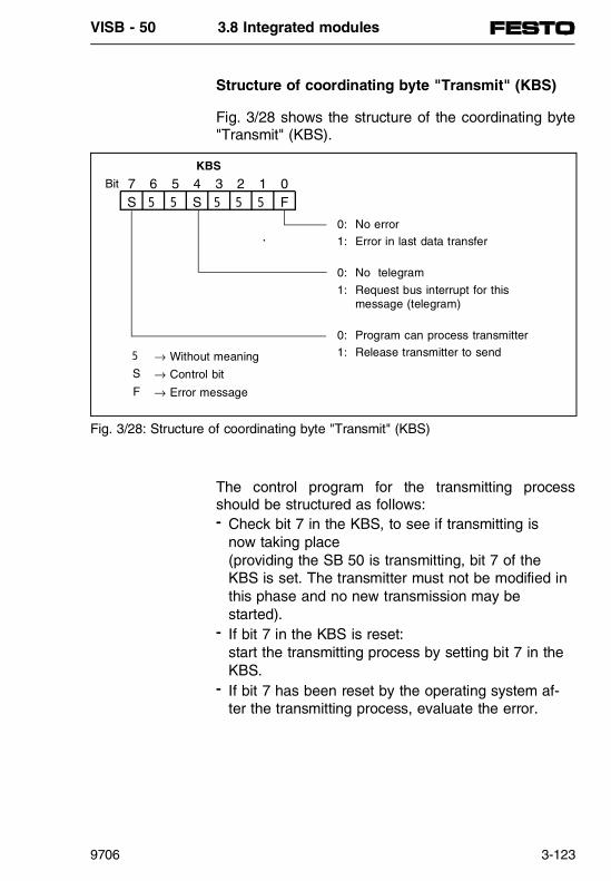
Structure of coordinating byte "Transmit" (KBS)
Fig. 3/28 shows the structure of the coordinating byte"Transmit" (KBS).
The control program for the transmitting processshould be structured as follows:- Check bit 7 in the KBS, to see if transmitting is
now taking place(providing the SB 50 is transmitting, bit 7 of theKBS is set. The transmitter must not be modified inthis phase and no new transmission may bestarted).
- If bit 7 in the KBS is reset: start the transmitting process by setting bit 7 in theKBS.
- If bit 7 has been reset by the operating system af-ter the transmitting process, evaluate the error.
Fig. 3/28: Structure of coordinating byte "Transmit" (KBS)
7 6 5 4 3 2 1 0S 5 5 S 5 5 5 F
KBS
Bit
0: No error
1: Error in last data transfer
0: No telegram
1: Request bus interrupt for thismessage (telegram)
0: Program can process transmitter
1: Release transmitter to send5 → Without meaning
S → Control bit
F → Error message
VISB - 50 3.8 Integrated modules
9706 3-123

By setting bit 4 in the KBS (telegram), you canachieve the following:- the transmitting programmer gives this telegram
priority (a telegram not yet sent can be overwritten) and
- the transmission is treated as a telegram by the receiver.
If there is an error, the operating system will set bit 0of the KBS. The error message is not valid until bit 7in the KBS is reset.
Receiving data
Prerequirements for receiving dataThe positions of the receiver and of the coordinatingbyte "Receive" (KBE) have been parametrized inDB1. Fig. 3/29 shows which information must bestored where with the receiver.
Fig. 3/29: Structure of receiver
FY1 Length of "net data"(in bytes)
FY2 Number of receiver0 = Master1...30 = Slaves
FY3 Data ("net data")(max. 64 bytes)
DW1 Length of"net data"
Number ofreceiver
DW2 1st. data 2nd. dataDW3 3rd. data ........
DL DR
VISB - 50 3.8 Integrated blocks
3-124 9706

Structure of the coordinating byte "Receive" (KBE)
Structure of the control program for receiving data:- Check by interrogating bit 7 in the KBE, whether or
not it is sensible to read data from the receiver. Bit 7 must be "0", in order that the receiver can beread.
In addition, the following errors and operating statescan be interrogated by the KBE: - At least one Slave has failed- Bus in RUN (STOP)- Data package received comes as telegram
Fig. 3/30: Structure of coordinating byte "Receive" (KBE)
7 6 5 4 3 2 1 0S 5 5 S 5 S F F
KBE
Bit
0: No error
1: Error in last data transfer
0: No slave failed
1: At least one slave failed
0: BUS in STOP
1: Bus in RUN
0: No telegram
1: Data arrive as telegram
0: Program can access receiver (operating system has no access)
1: Operating system transfers datato receiver (program has no access)
5 → Without meaning
S → Control bit
F → Error message
VISB - 50 3.8 Integrated modules
9706 3-125

Special features
If you have not reserved sufficient memory space forthe receiver, the memory space available will be filledup completely (flag range up to FY255, data block upto DW255) - the remaining data received cannot bestored. The SB 50 does not create an overrun mess-age in this case.
Examples of programs for sending and receiving dataare to be found in the manual SINEC L1 (chapter"Programming").
VISB - 50 3.8 Integrated blocks
3-126 9706

Programmable valve terminalswith
control block SB 50 / SF 50
Part 4: System description SF 50/DP-Master
PN
368
618

PN 368 618 is included in: Manual 174 826
Manual 174 827
Manual 174 828
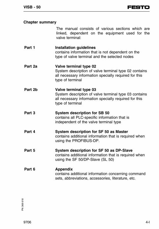
Chapter summary
The manual consists of various sections which arelinked, dependent on the equipment used for thevalve terminal:
Part 1 Installation guidelinescontains information that is not dependent on thetype of valve terminal and the selected nodes
Part 2a Valve terminal type 02System description of valve terminal type 02 containsall necessary information specially required for thistype of terminal
Part 2b Valve terminal type 03System description of valve terminal type 03 containsall necessary information specially required for thistype of terminal
Part 3 System description for SB 50contains all PLC-specific information that isindependent of the valve terminal type
Part 4 System description for SF 50 as Mastercontains additional information that is required whenusing the PROFIBUS-DP.
Part 5 System description for SF 50 as DP-Slavecontains additional information that is required whenusing the SF 50/DP-Slave (SL 50)
Part 6 Appendixcontains additional information concerning commandsets, abbreviations, accessories, literature, etc.
PN
368
618
VISB - 50
9706 4-I

Notes
___________________________________________
___________________________________________
___________________________________________
___________________________________________
___________________________________________
___________________________________________
___________________________________________
___________________________________________
___________________________________________
___________________________________________
___________________________________________
___________________________________________
___________________________________________
___________________________________________
___________________________________________
___________________________________________
___________________________________________
___________________________________________
___________________________________________
___________________________________________
___________________________________________
___________________________________________
VISB - 50
4-II 9706

Contents
4.1 SYSTEM SUMMARY.............................................4-3
SF 50 as master module in thePROFIBUS-DP field bus system .........................4-3
What are DP Siemens and DP Standard?..........4-5
Differences between DP Siemens and DP Standard ........................................................4-5
What does PROFIBUS-DP comprise? ................4-6
Structure with electronic bus medium(two wire cable)....................................................4-7
What is a bus segment?......................................4-7
Maximum extension of a bus segment................4-8
Parameters for a bus segment. ...........................4-9
Performance characteristics of the SF 50 and the components of the PROFIBUS-DP system......................................4-11
Field bus PROFIBUS-DP ..................................4-11
Parameterization Software.................................4-13
Requirements for operating COM PROFIBUS..4-14
PROFIBUS-DP bus cable connector (from Festo) .......................................................4-15
PG/PC interface component (optional)..............4-16
Interface component of the SF 50 (Master interface) ..............................................4-17
Display and operating elements ........................4-17
Pin allocation of the DP-Master interface..........4-19
Memory module of the master interface of the SF 50 master module ..................................4-19
PROFIBUS-DP bus cable connector of the SF 50 and two wire cable .......................4-21
Line termination .................................................4-22
PN
368
618
VISF - 50/DP-Master Contents
9706 4-III

Fitting bus cables to PROFIBUS-DP buscable connector .................................................4-23
4.2 PROCEDURE - FROM PLANNING TO COMMISSIONING .........................................4-27
Planning the structure........................................4-28
Structure of the field bus system.......................4-29
Considerations, before configuring the construction using COM PROFIBUS.................4-30
Configuration of construction using COM PROFIBUS...............................................4-31
STEP 5 description - User programs ................4-33
Commissioning the field bus system.................4-33
4.3 BASIC CONDITIONS AND INTRODUCTION TO THE PLANNING SOFTWARE COM PROFIBUS.................................................4-37
Requirements for the operation of COM PROFIBUS...............................................4-37
Requirements for configuring the data..............................................................4-38
Requirements for data transfer to the EEPROM integrated in the SF 50 DP-Master...............................................4-38
COM PROFIBUS preparations for operation with the SF 50 DP-Master.................4-40
Operater interface of COM PROFIBUS ............4-42
4.4 SAMPLE FOR THE PLANNING OF A STRUCTURE USING COM PROFIBUS .............4-47
Procedure ..........................................................4-48
Starting the COM PROFIBUS ..........................4-49
Selecting bus parameters..................................4-51
VISF - 50/DP-Master Contents
4-IV 9706
Entering host parameters ..................................4-53
Entering master parameters ..............................4-55
Entering slave parameters.................................4-57
Selecting slave parameters ...............................4-60
Selecting slave parameters through the menu bar......................................................4-61
Selecting slave parameters through the window "Slaves“.................................................4-62
Selecting slave parameters through the DP slave symbol ................................................4-63
Configuring the slave parameters......................4-64
Saving the plannned structure using COM PROFIBUS ...............................................4-67
Saving opportunities ..........................................4-67
Transferring a configured master system usingthe "SF 50-Download“ software from Festo ......4-68
Possible applications for the "SF 50-Download“ software...............................4-68
Requirements for operating "SF 50-Download“ 4-69
DOS version.......................................................4-69
Operation under DOS........................................4-69
MS Windows version .........................................4-70
Operation under MS Windows...........................4-71
Transferring a structure configured withan interface component .....................................4-73
Deleting a structure configured with the EEPROM integrated in the SF 50/DP-Master...4-74
VISF - 50/DP-Master Contents
9706 4-V
4.5 DIAGNOSISFault diagnosis in the PROFIBUS-DP system......................................4-79
Fault diagnosis with the display elements ................................................4-79
Diagnosis options in the STEP 5 control program of the SF 50 ........................................4-81
Station diagnosis ...............................................4-83
Booting up the SF 50 DP-Master on the bus..........................................................4-87
Requirements for booting up .............................4-87
Booting up the SF 50 DP-Master ......................4-88
Default parameter block ...................................4-89
Reporting in operating system data .................4-89
How the PROFIBUS-DP system works.............4-90
Power supply / mains power restoration / RUN<->STOP....................................................4-90
Reactions in relation to response monitoring....4-91
Reaction times in the system ............................4-93
VISF - 50/DP-Master Contents
4-VI 9706

4.1 SYSTEM SUMMARY
VISF- 50/DP-Master 4.1 System summary
9706 4-1
Contents
4.1 SYSTEM SUMMARY
SF 50 as master module in thePROFIBUS-DP field bus system.........................4-3
What are DP Siemens and DP Standard?..........4-5
Differences between DP Siemens and DP Standard .................................................4-5
What does PROFIBUS-DP comprise?................4-6
Structure with electronic bus medium (two wire cable) ...................................................4-7
What is a bus segment?......................................4-7
Maximum extension of a bus segment ...............4-8
Parameters for a bus segment............................4-9
Performance characteristics of the SF 50 andthe components of the PROFIBUS-DP system 4-11
Field bus PROFIBUS-DP ..................................4-11
Configuration software.......................................4-13
Requirements for operating COM PROFIBUS..4-14
PROFIBUS-DP bus cable connector (from Festo) .......................................................4-15
PG/PC interface component (optional)..............4-16
Interface component of the SF 50 (master interface)...............................................4-17
Display and operating elements ........................4-17
Pin allocation of the DP-Master interface..........4-19
Memory module of the master interface of the SF 50.......................................................4-19
PROFIBUS-DP bus cable connector of the SF 50 and two wire cable .......................4-21
Line termination .................................................4-22
Fitting bus cable to PROFIBUS-DP bus cable connector.................4-23
VISF - 50/DP-Master 4.1 System summary
4-2 9706

4.1 SYSTEM SUMMARY
SF 50 as master module in the PROFIBUS-DPfield bus system
The SF 50 is an SB 50 with a master module for thefield bus system PROFIBUS-DP. This system con-sists of the following components:
- Active bus slaves- Passive bus slaves- Field bus PROFIBUS-DP- PROFIBUS-DP system components
The following can be inserted as active bus stations(Master):
- SF 50/DP-Master, the SB 50 with a built-in Mastermodule
- The programmers PG720-770 or- PCs with an interface for the PROFIBUS-DP.
The Master module of the SF 50 is produced in com-pliance with the DP Standard (DIN 19245, part 3) andtherefore the following passive bus stations (Slaves)can be used:
- The field bus valve terminals FB9, FB13 and SF 50/DP-Slave from Festo
- Units of the remote peripheral system ET200, e.g.ET 200B and ET 200X from Siemens (DP Siemensand DP Standard)
- Field units, including those of other manufacturers,complying with the PROFIBUS-DP Standard (DIN19245, part 3)
VISF- 50/DP-Master 4.1 System summary
9706 4-3

PLEASE NOTEThere is a separate manual for the field bus valveterminals FB9 and FB13. There are separate ma-nuals for the remote peripheral devices ET 200U, ET 200B and ET 200X. The order number can befound in the Siemens catalogue.
This chapter examines the SF 50 as a Master moduleand, as an example, the field bus valve terminal FB9as a Slave module. The remote peripheral devicesfrom Siemens are shown in the system.
12 14 12 14
SIEMENS
RUN
STOP
BF
24VDC FUSE
L2-DP
PG
12 14
Programmerwith PROFIBUS-DPmodule
ET200U
Valve terminal with field bus nodes FB9
Valve terminal with SF 50
Further slaves of PROFIBUS-DP
STEP5
COM PROFIBUS
Fig. 4/1: Components of the remote peripheral system ET200
VISF - 50/DP-Master 4.1 System summary
4-4 9706

The inputs/outputs of the remote peripherals can beoperated from the control program like the local in-puts/outputs of the SB/SF 50.
Communications via the field bus PROFIBUS-DP arecompletely taken over by the module in SF 50 and bythe modules in the remote peripheral devices.
The configuration of the remote peripheral systems issupported by the configuration software COMPROFIBUS. This allows the compilation of the ad-dress lists and the evaluation of diagnostic data.Faults can therefore easily be located during com-missioning.
What are DP Siemens and DP Standard?
DP Siemens is a bus protocol that has been de-veloped by Siemens. This bus protocol was expandedinto an open and manufacturer-independent system incooperation with the PROFIBUS user organisation.
In order to differentiate between the two bus proto-cols, the newly produced bus protocol is called DPStandard in this manual.
Differences between DP Siemens and DP Standard
On the surface, there is hardly any difference be-tween DP Siemens and DP Standard. All the opera-ting possibilities available with a field bus valve termi-nal using the FB9 (DP Siemens), are also availableusing remote peripheral devices that comply with theDP Standard.
VISF- 50/DP-Master 4.1 System summary
9706 4-5

The PROFIBUS-DP also offers the following advantages:
- Slave stations that comply with the PROFIBUS-DPdraft standard can be connected to the PROFIBUS-DP,
- Masters, e. g. SF 50, that comply with thePROFIBUS-DP draft standard can communicatewith the slaves developed in compliance with thestandard provisions (e.g. ET200 U-DP from Siemens).
What does PROFIBUS-DP comprise?
The series of field bus standards PROFIBUS DIN 19245 covers a wide processing spectrum whichtherefore means that the bus system has universalapplications. Applications range from the control andcell level to the field level.
PROFIBUS-DP uses DIN 19245, part 1 and comple-ments the provisions set out for the special applica-tions in the sector of the remote peripherals.
DIN 19245, part 1 describes the bus access andtransfer protocols, together with the provisions for thenecessary transfer technology.
For applications in the sector of remote peripherals,where a short system reaction time is required, DIN E 19245, part 3 offers a possible solution.
The main task of the PROFIBUS-DP is the rapidcyclical data exchange between the programmablecontroller (Master station) and the low operation pe-ripheral devices (Slave stations).
VISF - 50/DP-Master 4.1 System summary
4-6 9706

PROFIBUS-DP offers the following features:
- the transmission of 1024 bits I/O data with 32slaves in less than 10 ms,
- comprehensive diagnosis concept,- reduced parametising and configuration require-
ments.
PLEASE NOTEThe SF 50 (DP Standard) is configured using theParameterization Software COM ET200 Windows(from v.2.x) or COM PROFIBUS. Both DP Siemensand DP Standard slaves can be operated.
Structure with electronic bus medium (two wire cable)
Master and slaves form stations on the PROFIBUS-DP field bus. Possible bus structures with master andslave stations are shown below.
What is a bus segment ?
A PROFIBUS-DP system consists of at least one bussegment. This bus segment consists of at least 2 sta-tions, one of which is an SF 50. A bus segment is thebus section between two terminating resistors. Thereare no branches within a bus segment.
SIMATICIntegrated
VISF- 50/DP-Master 4.1 System summary
9706 4-7
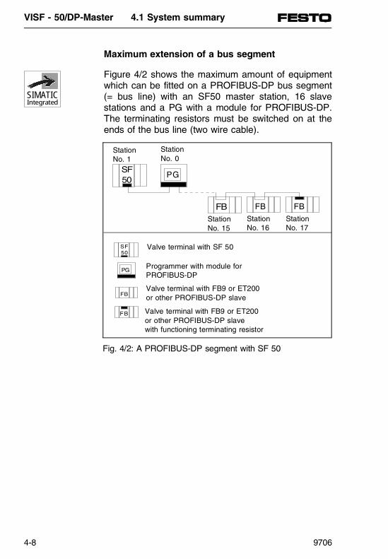
Maximum extension of a bus segment
Figure 4/2 shows the maximum amount of equipmentwhich can be fitted on a PROFIBUS-DP bus segment(= bus line) with an SF50 master station, 16 slavestations and a PG with a module for PROFIBUS-DP.The terminating resistors must be switched on at theends of the bus line (two wire cable).
FB
PG
FB FB
PG
FB
FB
SF50
SF50
StationNo. 1
StationNo. 0
StationNo. 15
StationNo. 16
StationNo. 17
Valve terminal with SF 50
Programmer with module forPROFIBUS-DP
Valve terminal with FB9 or ET200or other PROFIBUS-DP slave
Valve terminal with FB9 or ET200or other PROFIBUS-DP slavewith functioning terminating resistor
Fig. 4/2: A PROFIBUS-DP segment with SF 50
SIMATICIntegrated
VISF - 50/DP-Master 4.1 System summary
4-8 9706

Parameters for a bus segment
One segment can hold a maximum of 18 stations,with max. one SF 50 and max. one PG with a modulefor PROFIBUS-DP.
The maximum cable length of the PROFIBUS-DP bussegment is dependent on the baud rate (table 4/1):
Baudrate(in kBit/s)
Max. cable length of asegment (in m)
9.6 120019.2 120093.75 1200187.5 1000500 4001500 200
Table 4/1: Permitted cable length of a segment
VISF- 50/DP-Master 4.1 System summary
9706 4-9

VISF - 50/DP-Master 4.1 System summary
4-10 9706
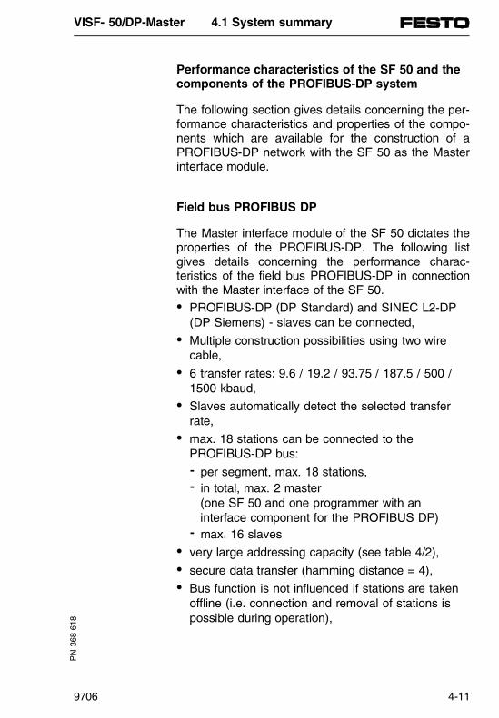
Performance characteristics of the SF 50 and thecomponents of the PROFIBUS-DP system
The following section gives details concerning the per-formance characteristics and properties of the compo-nents which are available for the construction of aPROFIBUS-DP network with the SF 50 as the Masterinterface module.
Field bus PROFIBUS DP
The Master interface module of the SF 50 dictates theproperties of the PROFIBUS-DP. The following listgives details concerning the performance charac-teristics of the field bus PROFIBUS-DP in connectionwith the Master interface of the SF 50.• PROFIBUS-DP (DP Standard) and SINEC L2-DP
(DP Siemens) - slaves can be connected,• Multiple construction possibilities using two wire
cable,• 6 transfer rates: 9.6 / 19.2 / 93.75 / 187.5 / 500 /
1500 kbaud,• Slaves automatically detect the selected transfer
rate,• max. 18 stations can be connected to the
PROFIBUS-DP bus:- per segment, max. 18 stations,- in total, max. 2 master
(one SF 50 and one programmer with an interface component for the PROFIBUS DP)
- max. 16 slaves• very large addressing capacity (see table 4/2),• secure data transfer (hamming distance = 4),• Bus function is not influenced if stations are taken
offline (i.e. connection and removal of stations ispossible during operation),
PN
368
618
VISF- 50/DP-Master 4.1 System summary
9706 4-11

• Comprehensive diagnosis options:- with fault and diagnosis LEDs - in the control program in accordance with
EN 50170
PLEASE NOTEThe SF 50 with DP-Master interface does not allowthe connection of DP-Slaves, which are not limitedto a message length of 32 bytes. The SF 50 canonly process a maximum of 32 bytes input and out-put data per DP Slave.
SIMATICIntegrated
Byte addressesin PII and PIO
Inputs Outputs
0...6 IB0...6 56 local inputs QB0...7 64 localoutputs7 IB7 8 I local
diagnosis ofthe valveterminal
8...125 IB8...125 118 byte Ifor digital,analogue andintelligentperipherals
QB8...127 120 byte Ofor digital,analogue andintelligentperipherals
126...127 IB126IB127
16 I diagnosisPROFIBUS-DP
Table 4/2: Addressing capacity of the SF 50
VISF - 50/DP-Master 4.1 System summary
4-12 9706
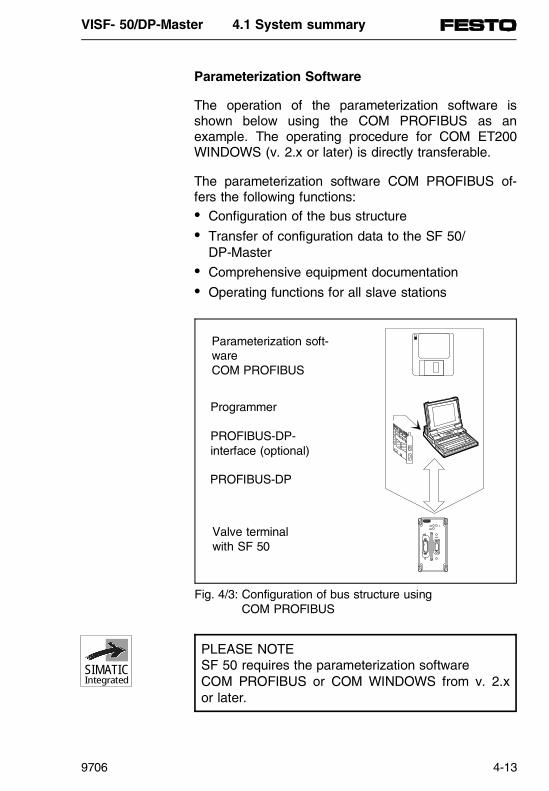
Parameterization Software
The operation of the parameterization software isshown below using the COM PROFIBUS as anexample. The operating procedure for COM ET200WINDOWS (v. 2.x or later) is directly transferable.
The parameterization software COM PROFIBUS of-fers the following functions:• Configuration of the bus structure• Transfer of configuration data to the SF 50/
DP-Master• Comprehensive equipment documentation• Operating functions for all slave stations
PLEASE NOTE SF 50 requires the parameterization software COM PROFIBUS or COM WINDOWS from v. 2.xor later.
SIMATICIntegrated
Parameterization soft-wareCOM PROFIBUS
Programmer
PROFIBUS-DP-interface (optional)
PROFIBUS-DP
Valve terminalwith SF 50
Fig. 4/3: Configuration of bus structure using COM PROFIBUS
VISF- 50/DP-Master 4.1 System summary
9706 4-13

Requirements for operating COM PROFIBUS
COM PROFIBUS runs on the user interface MS Win-dows. Prior knowledge of MS-Windows is assumed.
To use COM PROFIBUS without any restrictions, youneed:• Operating system MS DOS (v. 5.0 or later)• User interface MS Windows (v. 3.x or later)• minimum 4 MB free RAM• minimum 5 MB free memory on the hard drive• minimum 386 processor.
VISF - 50/DP-Master 4.1 System summary
4-14 9706

PROFIBUS-DP bus cable connector (from Festo)
The SF 50 is an IP 65 PLC and therefore requires abus cable connector with the protection class IP 65.This connector links the SF 50 over a two-wire,screened bus line, to the field bus valve terminal withan FB9, an ET 200 Station or another PROFIBUS-DPSlave.
Fig. 4/4: PROFIBUS-DP bus cable connector from Festo
SIMATICIntegrated
VISF- 50/DP-Master 4.1 System summary
9706 4-15

PG/PC interface component (optional)
The interface component is used to transfer the con-figuration data from the PG/PC to the SF 50, as anEEPROM is already integrated into the SF 50. TheE(E)PROM programmer and erasing device are notrequired with the SF 50.
To transfer the data with the COM PROFIBUS to theSF 50, use one of the following interfaces:
Interface Baud rate NoteMPI card 9.6 kbaud to
500 kbaudMPI card is already integrated in the 720,740 and 760 PG’s
DP12-ISA card(CP 5411)
9.6 kbaud to12 MBaud
Connecting 730, 740, 750, 770 PGs and PTs
CP 5511 9.6 kbaud to12 MBaud
Connecting PC with PCMCIA slot
NOTE
The configuration data can also be transferred via thePG interface using the ’Festo SF 50-Download-Tool’to the EEPROM integrated in the SF 50 (see chapter4.4).
SIMATICIntegrated
VISF - 50/DP-Master 4.1 System summary
4-16 9706

Interface component of the SF 50 (Master interface)
The Master interface component of the SF 50 enablesthe remote extension of the SB 50 with thePROFIBUS-DP.
Display and operating elements
Like the SB 50, the SF 50 has no operating elements.The PROFIBUS-DP Master is supplied with powerthrough the power supply of the valve terminal and isswitched to RUN or STOP through the programmerand the PLC "START/STOP" function simultaneouslywith the built-in PLC.
PN
368
618
RUN BF
L2-DP
PG
STOP
BF LED Display(BUS FAULT = red)
DP-Master interface forPROFIBUS-DP
SIEMENS
Fig. 4/5: Structure of the SF 50
SIMATICIntegrated
VISF- 50/DP-Master 4.1 System summary
9706 4-17

LED BF LEDRUN
LEDSTOP
Significance Remedy
Off Lightsup
Off All configured DP slavesare addressable
-
Blinks Lightsup
Off At least one DP slave isnot addressable
Check the DP slaves andevaluate the slavediagnosis.
Lightsup
Off Lightsup
Bus short circuit ormissing terminator resistorsor configuration error
Check the buscable and the busstructure.
After the fault isfixed, the SF 50system must beswitched off andthen on again.
Off Lightsup
Lightsup
Acceleration delay orOB21/OB22
-
Off Off Flickers DP parameter block isbeing transferred within theSF 50 between thecontroller andcommunications processoror the STEP 5 userprogram is being saved.
-
VISF - 50/DP-Master 4.1 System summary
4-18 9706

Pin allocation of the DP-Master interface
The remote peripheral devices are connected over theDP-Master interface to the SF 50 over thePROFIBUS-DP.
The DP-Master interface is based on a 9-pin D-sub-socket matching the PROFIBUS-DP.
Memory module of the master interface of the SF 50
To hold the PROFIBUS system parameters and theconfiguration data, a 12 KB memory area is reservedin the EEPROM of the SF 50. The EEPROM is pro-grammed by a correct transfer of the data from theprogrammer to the SF 50 and can be overwritten by anew data transfer. The PT function "delete" deletes allthe system parameters and configuration data in thereserved section of the EEPROM and resets them tothe default values.
View PINNo.
Signal name Designation
123456789
--RxD / TxD-PRTSM5V2P5V2-RxD / TxD-N-
Functional earth-Data line BRequest to sendData earthSupply Plus-Data line A-
Table 4/3: Pin assignment of the PROFIBUS-DP interface
5
4
3
2
1
9
8
7
6
SIMATICIntegrated
VISF- 50/DP-Master 4.1 System summary
9706 4-19

Mains on
SF 50 in STOP operatingmode
DOWNLOAD with COM PROFIBUS
Fault ?
Parameter block in RAM of SF 50
Red LED "BF" lights up
MAINS OFF ⇒ ONor DELETE
Activation of the parameter block
Red LED "STOP" flickers:Parameter block is being saved
Red LED "STOP" lights up:Parameter block saved in
EEPROM
Yes
no
DOWNLOAD with Festo Download-Tool
Fig. 4/6: Transferring/saving of system parameters and configuration data
VISF - 50/DP-Master 4.1 System summary
4-20 9706

PROFIBUS-DP bus cable connector of the SF 50 and two wire cable
Maximum cable lengths are achieved by using a twowire twisted and screened cable with the followingproperties:
The maximum cable lengths given in table 4/5 areguaranteed with the bus cable for PROFIBUS-DP(Siemens order No. 6XV1 830-0AH10).
The branch line capacitance must only be taken intoaccount when the bus cable is not directly mountedon the bus cable connector (e.g. when using a busterminal). The branch line capacitance can then bedivided by the number of connected slaves.
Characteristics ValuesSurge impedance ca. 135...160 Ω (f = 3...20 MHz)Loop resistance ≤ 115 Ω /kmWorking capacitance 30 nF/kmDamping 0.9 dB/100 (f = 200 kHz)Permissible wire cross-section for bus cableconnector 0.3 mm2 ...1 mm2
Permissible cable diameter 8 mm ± 0.5 mm
Table 4/4: Features of the bus cable
Transfer rate(kBits/s)
Max. permissible cable length of the bus cable per segment (m)
Max. branch line capacitance
(nF) Without slaves, Remote segment
With slaves
9.6 3300 1200 14019.2 2800 1200 7093.75 2000 1200 15187.5 1600 1000 7.5500 1200 400 3
1500 500 200 1
Table 4/5: Length of bus cable in relation to the transfer rate
VISF- 50/DP-Master 4.1 System summary
9706 4-21

Example:The capacitance of the branch line used is 100 pF/m. This means that, with a transfer rate of 500 kbps, 15slaves per 2 m of branch line can be connected.
Line termination
A bus segment must be closed with its surge imped-ance. The terminating resistor must be activated withthe last bus station of a segment (for switch positionon bus cable connector, see figure 4/7).
The terminating resistors must be activated at thesegment start (first slave, e.g. SF 50) and the seg-ment end (last slave).
PLEASE NOTEIf the terminating resistors are not correctly acti-vated this may lead to a STOP status of the bus.The remote peripherals (e.g. inputs and outputs)can then no longer be addressed.
Fig. 4/7: Terminating resistor switched on / off
A B A B
Terminating resistor OFF
Terminating resistor ON
VISF - 50/DP-Master 4.1 System summary
4-22 9706
Fitting bus cables to PROFIBUS-DP bus cable connector
The following must be noted when connecting the cables:• The same wires (green/red for PROFIBUS-DP
cable) must be fitted to connection A or B (e.g.connection A is always linked with the green wireand connection B with the red wire)
and
• The cable must be insulated in such a manner thatthe screening is directly underneath the pressure clamp.
The connection method for the PROFIBUS-DP buscable connector as per protection class IP 65 is de-scribed in detail in part 1, chapter 1.3, FBS-SS-9 Fieldbus connector assembly.
VISF- 50/DP-Master 4.1 System summary
9706 4-23

VISF - 50/DP-Master 4.1 System summary
4-24 9706

4.2 PROCEDURE
PN
368
618
VISF- 50/DP-Master 4.2 Procedure
9706 4-25

Contents
4.2 PROCEDURE - FROM PLANNING TO COMMISSIONING ...............................................4-27
Planning the structure........................................4-28
Structure of the field bus system.......................4-29
Considerations before configuring the structure using COM PROFIBUS......................4-30
Configuration of structure using COM PROFIBUS...............................................4-31
Writing the STEP 5 user program.....................4-33
Commissioning the field bus system.................4-33
VISF - 50/DP-Master 4.2 Procedure
4-26 9706

4.2 PROCEDURE - FROM PLANNING TO COMMISSIONING
This chapter offers an overview of the procedures inthe field bus system PROFIBUS-DP. It is aimed atreaders who have no previous experience with thePROFIBUS-DP.
It is a complete guide to the manual, from planning tocommissioning, and includes wiring, configuration withthe COM PROFIBUS and writing the STEP 5 userprogram.
Reading this chapter will show how to proceed with the field bus system PROFIBUS-DP of the SF 50/DP-Master and how to find further informationin this manual.
VISF- 50/DP-Master 4.2 Procedure
9706 4-27

Planning the structure
This section shows what must be considered first dur-ing the planning stage. Fundamental for planning thestructure is a layout:
Step Task Further information
1 Distribute the inputs and outputs to thesites where they are required.
2 Arrange the inputs and outputs of thecorresponding DP slaves
Manuals on the DP slaves
3 Determine the sites for the DP slavesand the programmable controller(s).
Manuals on the DP slaves
4 Calculate the distances between thesites. These calculations show themaximum attainable baud rates.
See table 4/1
Table 4/6: Structural planning
VISF - 50/DP-Master 4.2 Procedure
4-28 9706

Structure of the field bus system
This section shows what must be taken into consider-ation in the mechanical and electrical construction ofthe components.
Step Task Further information
1 First determine the position of the cablechannels and therefore the distancebetween the cables.
2 Fix the DP slaves and the programmablecontrollers to their positions.
Manuals for the DP slaves
3 Connect the power supply, sensors andactuators to the DP slaves.
Manuals for the DP slaves
4 Connect all bus stations with theappropriate bus cable connector to thefield bus PROFIBUS-DP.
e.g. see figure 4/7
5 Activate the terminating resistor of the firstand last field bus slave (of a segment).
e.g. see figure 4/7
Table 4/7:
VISF- 50/DP-Master 4.2 Procedure
9706 4-29

Considerations before configuring the structurewith COM PROFIBUS
The following section shows what must be taken intoconsideration before using the COM PROFIBUS.
There are two main possibilities for implementing theconfiguration with COM PROFIBUS and when writingthe user program:
• Firstly, plan the structure with COM PROFIBUSand let it automatically assign all station numbersand addresses in the STEP 5 user program. Thenprint out the equipment documentation and usethis as a basis for the STEP 5 user program.
• Configuring with COM PROFIBUS and recordingthe STEP 5 user program take place simulta-neously. The following must be determined beforeinitiating the configuration with COM PROFIBUS:
The following must be determined before initiatingCOM PROFIBUS:
Step Task Further information
1 Which DP slave should be assigned whichstation number.
2 Which addresses the DP slaves shouldoccupy in the STEP 5 user program.
3 The requirements of the equipmentdetermine whether response monitoringshould be activated for the DP slaves.
See table 4/24
Table 4/8: COM PROFIBUS considerations
VISF - 50/DP-Master 4.2 Procedure
4-30 9706

Configuring a structure using COM PROFIBUS
The following chapter summarises the procedure forconfiguring a structure with COM PROFIBUS.
To configure and save the structure, follow themethod below:
Step Task Further information
1 After starting COM PROFIBUS, input theparameters of the individual components to
See chapter 4.4
• The bus
• The DP-Master (characteristics of the field bus module)
• The host (characteristics of the PLC)
2 Configure the individual DP slaves. Input the following parameters.
Some examples are given below:
See chapter 4.4
• Slave numbers
• Address identifiers (number of inputs and outputs)
• Addresses in the user program (parameters)
Always enter the slave parameters after themaster parameters, as the slave parametersmay switch off the response monitoring for theDP slaves that was previously switched on withthe master parameters.
VISF- 50/DP-Master 4.2 Procedure
9706 4-31

3 Once the configuration of the structure iscomplete, save the whole configuration. There are two data transfer options available:
See chapter 4.4
• Export the data via a PROFIBUS interfacecomponent (e.g. an MPI card) directly intothe built-in EEPROM of the SF 50/DP-Master(interface PROFIBUS L2-DP).
• Export the data as a binary file and transferthe data using the Festo Software Tool "SF 50-Download" to the built-in EEPROM of the SF 50/DP-Master (PG interface).
4 Finally, print out the equipment documentation.
Table 4/9: Configuration of construction using COM PROFIBUS
VISF - 50/DP-Master 4.2 Procedure
4-32 9706
Writing the STEP 5 user program
Use the following information to record the STEP 5user program:
Commissioning the field bus system
The decentralised peripheral system ET 200 can be activated as follows:
Step Task Further information1 Which DP slaves occupy which addresses
in the STEP 5 user program.Equipmentdocumentation withCOM PROFIBUS
2 How to access the remote peripheralsusing the STEP 5 user program. See chapter 4.4
3 How to evaluate diagnostic messages usingthe FB 230 diagnostic reports.
See chapter 4.5
Table 4/10: Writing the STEP 5 user program
Step Task Further information
1 Allocate a DIP-switch to each DP slave (e.g.FB9 or ET 200U) or use software (e.g. ET 200C) to assign a valid stationnumber.
See manual on the DP slaves
2 Activate the bus stations in a specificsequence.
See chapter 4.5
3 Activate all field bus stations using the PGinterface of the SF 50/DP-Master. Thefunctions of the DP slaves can easily betested using the function "Force Variables" inthe STEP 5 programming package.
See chapter 3.3
Table 4/11: Commissioning the field bus system
VISF- 50/DP-Master 4.2 Procedure
9706 4-33

VISF - 50/DP-Master 4.2 Procedure
4-34 9706

4.3 REQUIREMENTS
PN
368
618
VISF- 50/DP-Master 4.3 Requirements
9706 4-35

Contents
4.3 BASIC REQUIREMENTS AND INTRODUCTION TO THE COM PROFIBUS CONFIGURATION SOFTWARE ........................................................4-37
Requirements for operating COM PROFIBUS..4-37
Requirements for configuring the data ..............4-38
Requirements for data transfer to the integrated EEPROM in the SF 50/DP-Master ...............................................4-38
Preparing COM PROFIBUS for operation with the SF 50/DP-Master .................4-40
COM PROFIBUS user interface........................4-42
VISF - 50/DP-Master 4.3 Requirements
4-36 9706

4.3 BASIC REQUIREMENTS AND INTRODUCTION TO THE COM PROFIBUS CONFIGURATION SOFTWARE
Why do you need COM PROFIBUS?
Configuring software COM PROFIBUS is needed for:• Configuration of the bus structure, the host, the
DP-Master and the DP slaves.• For writing the data (Download) to the integrated
EEPROM of the SF 50/DP-Master or reading (uploading) this data.
• Comprehensive equipment documentation
Requirements for operating COM PROFIBUS
COM PROFIBUS runs on the user interface MS Win-dows. Prior knowledge of MS Windows is assumed.
• Operating system MS DOS (v. 5.0 or later)• User interface MS Windows (v. 3.1.x or later)• minimum 4 MB free RAM• minimum 5 MB free memory on the hard drive• minimum 386 processor
The following section assumes the correct installationof the COM PROFIBUS. Installation instructions canbe found in the information material for COMPROFIBUS provided by Siemens.
VISF- 50/DP-Master 4.3 Requirements
9706 4-37

Requirements for configuring the data
COM PROFIBUS uses type files for configuration andparametrising which contain all information, arrangedaccording to the station model family, concerning the"appearance" of a PROFIBUS-DP station.PROFIBUS-DP stations can be:
• Slave stations• Master stations
The type files for the SF 50/DP-Master are includedon a disk in this manual and must be stored in aCOM PROFIBUS directory.
Requirements for data transfer to the EEPROM integrated in the SF 50/DP-Master
There are two different possibilities of data transferavailable with the SF 50/DP-Master from the COMPROFIBUS to the integrated EEPROM of the SF 50/DP-Master:
• "FESTO SF 50-Download“ software tool to transfera binary file created with COM PROFIBUS via thePG interface
• Data transfer using an interface component forPC/PT over the PROFIBUS-DP and field bus inter-face (L2-DP). The appropriate installation instructions are avail-able with the interfaces. To connect the PGs/PCsto the "L2-DP“ interface, use the PG connectingcable from Siemens.
VISF - 50/DP-Master 4.3 Requirements
4-38 9706

Interface Note Manufacturer and sales
Integrated MPIinterface
The MPI card is already integratedin the PG720, PG740 and PG760.
Siemens AG
MPI card The MPI card is available as an ISAplug-in card for the PG730, PG750,PG770 or the PC.
Siemens AG
DP12-ISA card(CP 5411)
ISA plug-in card for the connectionof PG730, PG750, PG770 or PC.
Siemens AG
CP 5511 PCMCIA plug-in card for theconnection of PC with a PCMCIAmodule slot (e.g. Notebook)
Siemens AG
Table 4/12: Interfaces for COM PROFIBUS
VISF- 50/DP-Master 4.3 Requirements
9706 4-39

Preparing COM PROFIBUS for operation with theSF 50/DP-Master
Each PROFIBUS-DP-Master is formally described in atype file for the operation of the COM PROFIBUS.These type files contain data that enables easy inputand the interrogation of limiting values and parame-ters within COM PROFIBUS.
Some examples are given for the model files of theSF 50/DP-Master :
• The number of slave stations is limited to 16 slaves• Address space limited to IW8 to IW124 and
OW8 to OW126.
To install the type files of the SF 50/DP-Master for theCOM PROFIBUS, follow the instructions below:
1. Copy the file "FEFB50XD.2MH“ from the directory A:\SF50\COMWIN20\MASTER\ on the accompanying disk to the directory ..\MASTERS\ in COM PROFIBUS
2. Copy the files "FE-TYP3N.BMP" and "FE-TYP3S.BMP" from the directory A:\SF50\COMWIN20\BMP on the accompanyingdisk to the directory ...\BITMAPS\ in COM PROFIBUS
3. Start up COM PROFIBUS
4. Go to FILE/NEW and
5. Select SF 50/DP-Master from the selection of DP-Masters in the window "Master & host selec-tion -> Master station type" in COM PROFIBUS
6. Station No. = 1
SIMATICIntegrated
VISF - 50/DP-Master 4.3 Requirements
4-40 9706
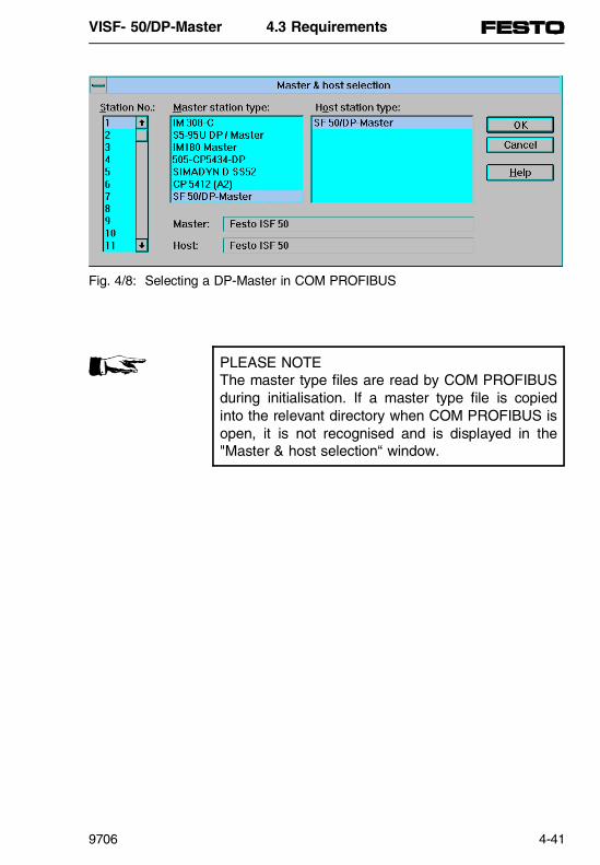
PLEASE NOTEThe master type files are read by COM PROFIBUSduring initialisation. If a master type file is copiedinto the relevant directory when COM PROFIBUS isopen, it is not recognised and is displayed in the"Master & host selection“ window.
Fig. 4/8: Selecting a DP-Master in COM PROFIBUS
VISF- 50/DP-Master 4.3 Requirements
9706 4-41
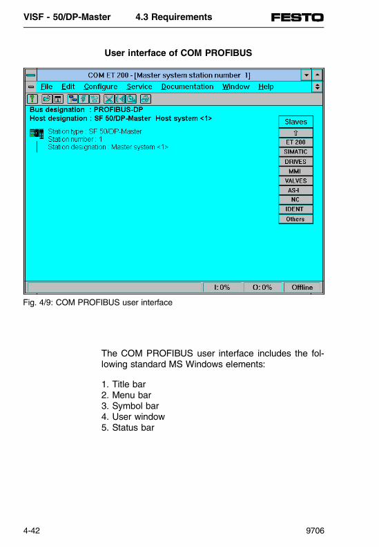
User interface of COM PROFIBUS
The COM PROFIBUS user interface includes the fol-lowing standard MS Windows elements:
1. Title bar2. Menu bar3. Symbol bar4. User window5. Status bar
Fig. 4/9: COM PROFIBUS user interface
VISF - 50/DP-Master 4.3 Requirements
4-42 9706

1. Title barThe title bar always contains the name of the applica-tion
2. Menu barThe menu bar contains the names of the various se-lection menus (see table 4/13).
3. Symbol barThe symbol bar contains the symbols that simplify theselection of menu commands (see table 4/13).
4. User windowThe user window is where the construction of the busis implemented using the graphics symbols. Eachuser window contains a DP-Master where the cor-responding DP slaves can be graphically arranged.Double-clicking on the symbol or the designationautomatically moves the user to the window for enter-ing individual parameters.
5. Status barThe status bar contains a short description of the cur-rent command, the current COM PROFIBUS activityor operating instructions.In addition, it shows how much address space hasalready been used for the inputs and outputs.
VISF- 50/DP-Master 4.3 Requirements
9706 4-43

Menu Important commands Symbols Menucommands
File Starts the configuration of a bus structure File\New
Opening program files File\Open
Saving and closing program files File\Save
Saving master systems on the DP-Master(SF 50/DP-Master).
File\Export\DP-Master
Saving current master system on abinary file.
File\Export\Binary file
Reading the master system of the DP-Master (SF 50/DP-Master).
File\Import\DP-Master
Printing equipment documentation (In menu field "Documentation“ opendocumentation window).
File\Print
Process Cutting, copying, pasting and deletingselected sections
Configu-ration
Entering bus, host, master and slaveparametersCreating new Master system Configure\
New Mastersystem
Documen-tation
Production of equipment documentation
Service Setting the PG/PC interface parametersWindow Changing the screen viewHelp Windows Help files for the theme Help \
Contents
Table 4/13: Important menu fields and symbols in COM PROFIBUS
VISF - 50/DP-Master 4.3 Requirements
4-44 9706

4.4 CONFIGURATION
PN
368
618
VISF- 50/DP-Master 4.4 Configuration
9706 4-45

Contents
4.4 SAMPLE FOR THE PLANNING OF A STRUCTURE USING COM PROFIBUS .........4-47
Procedure ..........................................................4-48
Starting the COM PROFIBUS ...........................4-49
Selecting bus parameters..................................4-51
Entering host parameters ..................................4-53
Entering master parameters ..............................4-55
Entering slave parameters.................................4-57
Selecting slave parameters ...............................4-60
Selecting slave parameters from the menu bar 4-61
Selecting slave parameters with the "Slave" window ..................................................4-62
Selecting slave parameters with theDP slave symbol................................................4-63
Configuring the slave parameters .....................4-64
Saving a structure configured with the COM PROFIBUS .................................4-67
Saving methods .................................................4-67
Transferring a configured master system usingthe "SF 50 Download“ software from Festo......4-68
Possible applications of the "SF 50-Download" software...............................4-68
Requirements for operating "SF 50-Download" 4-69
Operation under DOS........................................4-69
MS Windows version .........................................4-70
Operation under MS Windows ..........................4-71
Transferring a structure configured with an interface component ..........................................4-73
Deleting a structure configured with the EEPROM integrated in the SF 50/DP-Master...4-74
VISF - 50/DP-Master 4.4 Configuration
4-46 9706

4.4 SAMPLE FOR THE CONFIGURATION OF A STRUCTURE USING COM PROFIBUS
The following example uses a sample structure todemonstrate configuration using the COM PROFIBUS.
Two field bus valve terminals from Festo are used asslave stations with a PROFIBUS-DP connection (FB 9).
The following example uses a simple structure to ex-plain the configuration and programming of aPROFIBUS-DP system with an SF 50/DP-Master,consisting of:
• 1 master station: valve terminal with SF 50/DP-Master
• 2 slave stations: valve terminals with FB9• Bus line from Siemens• 1 SINEC-L2 bus cable connector (protection class
IP 65 - 9-pin sub-D) for SF 50/DP-Master fromFesto
• 3 bus cable connectors (protection class IP 65 - 4-pin rounded connector) for FB9 from Festo
• Programmer, with or without interface component(e.g. MPI) as required
Basic requirements:
• COM PROFIBUS is installed on the programmer• Type files for valve terminals with FB 9 are
installed (see "FB 9“ manual)
VISF- 50/DP-Master 4.4 Configuration
9706 4-47

Procedure
Structuring the PROFIBUS-DP system:
Using a simple example, the following shows the pro-cedure for configuring a structure with COM PROFIBUS:
• Start up COM PROFIBUS• Enter bus parameters• Enter host parameters• Enter master parameters• Enter slave parameters for valve terminals with FB9 • Print equipment documentation and• Save and transfer the structure to the integrated
EEPROM of the SF 50/DP-Master.
SF 50 Master station 1
FB9 Slave station No. 3
FB9 Slave station No. 6
FB9
SF 50
8 x
I
2 I-
valv
es
8 x
I
4 x
O
8 x
I
8 x
I
4 x
O
4 x
I
4 x
I
4 x
O FB9
2 M
-val
ves
2 I-
valv
es2
M-v
alve
s
2 I-
valv
es2
M-v
alve
s
2 I-
valv
es2
M-v
alve
s
2 I-
valv
es2
M-v
alve
s
Fig. 4/10: Structure of a simple PROFIBUS-DP system
VISF - 50/DP-Master 4.4 Configuration
4-48 9706

Starting the COM PROFIBUS
To work with COM PROFIBUS:
1. Start up MS Windows
2. Double-click on the symbol for COM PROFIBUS.Result: COM PROFIBUS is opened.
3. Go to File/New
4. Select the "SF 50/DP-Master“ for the DP-Masterand the associated Host.
5. Select number "1“ as the station number
6. Confirm by clicking "OK“Result: COM ET 200 Windows creates a windowwith graphic symbols for the master system withthe station number ”1”.
Fig. 4/11: Selection of the DP-Master
VISF- 50/DP-Master 4.4 Configuration
9706 4-49

Fig. 4/12: DP-Master system with SF 50/DP-Master
VISF - 50/DP-Master 4.4 Configuration
4-50 9706

Selecting bus parameters
To insert the parameters for the bus:
1. Double-click in the user window on the line "Bus designation“.
Result: The "Bus parameters“ window appears.
2. Insert a name as the bus designation
3. Select the bus profile "DP with S5-95U“
4. Select a baud rate
5. Confirm by clicking "OK“
Result: The inserted bus parameters are stored andthe screen returns to the user window.
VISF- 50/DP-Master 4.4 Configuration
9706 4-51

PLEASE NOTEWhen using the parameterization software COM ET 200 Windows, the following message appears "Tocreate the master, COM ET 200 Windows mustcomply with the set baud rate. Should the mastersystem be accepted?“. This message must beanswered with "Yes“. The default values are thenset at
- Bus profile "PROFIBUS-DP“ and- Baud rate "187.5“ .
Finally, select the parameters
- Bus profile "DP with S5-95U“- Baud rate "1500.0“
Designation Significance Defaultsettings
Bus designation Enter up to 40 characters as a name for thebus system.
-
Bus profile DP with S5-95U: There is at least one SF 50/DP-Master on the bus
DP with S5-95U
Baud rate With the baud rate you can select a transferspeed of between 9.6 kbaud and 1500 kbaud.
1500 kbaud
Setparameters
Using this operating stage, you can changevarious PROFIBUS-DP parameters (see alsothe on-line help in COM PROFIBUS). NOTE: In normal cases no changes are necessary.
-
Table 4/14: Significance of the bus parameters
VISF - 50/DP-Master 4.4 Configuration
4-52 9706

Entering host parameters
To enter the host specification:
1. Double-click in the user window on the line "Host designation“.
Result: The window "Host parameters“ appears.
2. Insert a name as the host designation.
3. Leave the power-up delay period as the defaultvalue and
4. Confirm by clicking "OK“.
Result: The host parameters entered are stored andthe screen returns to the user window.
20
VISF- 50/DP-Master 4.4 Configuration
9706 4-53

PLEASE NOTEWhen using the parameterization software COMET 200 for Windows v. 2.1, the default value for thepower-up delay period is set at "0s“. This periodcannot be changed (like the S5-95U/DP-Masterfrom Siemens).
Designation Significance Defaultsettings
Host designation Enter up to 40 characters as a name for thehost system.
-
Host type, in theSF 50/DP-Master
Master station type and host station type areidentical (like the S5-95U/DP-Master fromSiemens).
SF 50/DP-Master
Power-up delay The booting of the SF 50/DP-Master is main-tained for the time required for all DP slavesconfigured by COM PROFIBUS addressedby the SF 50/DP-Master. At longest periodfor any given booting delay period.
20 s
Reserve inputs With these parameters you can reserveinput address space.
Reserve outputs With these parameters output address areascan be reserved.
Table 4/15: Significance of the Host parameters
VISF - 50/DP-Master 4.4 Configuration
4-54 9706

Entering master parameters
To complete the master parameters:
1. Double-click in the user window on the symbol forthe SF 50/DP-Master.
Result: The "Master parameters“ window appears.
2. Insert a name as the station designation.
3. Leave the response monitoring for the slaves onthe default value "Yes“ (ticked).
4. Confirm by clicking "OK“.
Result: The inserted master parameters are savedand the screen returns to the user window.
VISF- 50/DP-Master 4.4 Configuration
9706 4-55

WARNINGIf the response monitoring is switched off, undercertain circumstances in cases of error the outputsof the corresponding DP slaves are not returned to ”0”.It is therefore recommended that the responsemonitoring is only switched off during commissioning.
Designation Significance Defaultsettings
Station designation Enter up to 40 characters as a name for themaster system.
-
Host association Cannot be changed for the SF 50/DP-Master SF 50/DP-Master
Addressing method Cannot be changed for the SF 50/DP-Master LinearError-reportingmethod
Cannot be changed for the SF 50/DP-Master None
Response monitoring forslave
With the response monitoring there is thepossibility that the DP slave can react to afault from the DP-Master or to aninterruption of data traffic on the bus. If the DP slave is not addressed within theconfigured response monitoring period, thenthe DP slave goes into the safe status (alloutputs are set to ”0”). If the responsemonitoring "Yes" is selected (corresponds toa cross in the box), then this conditionapplies to all the DP slaves that are assigned to the DP-Master. It is howeverpossible, e.g. for commissioning, to switchoff the response monitoring for individual DP slaves (slave parameters).
Yes
Table 4/16: Significance of the master parameters
VISF - 50/DP-Master 4.4 Configuration
4-56 9706
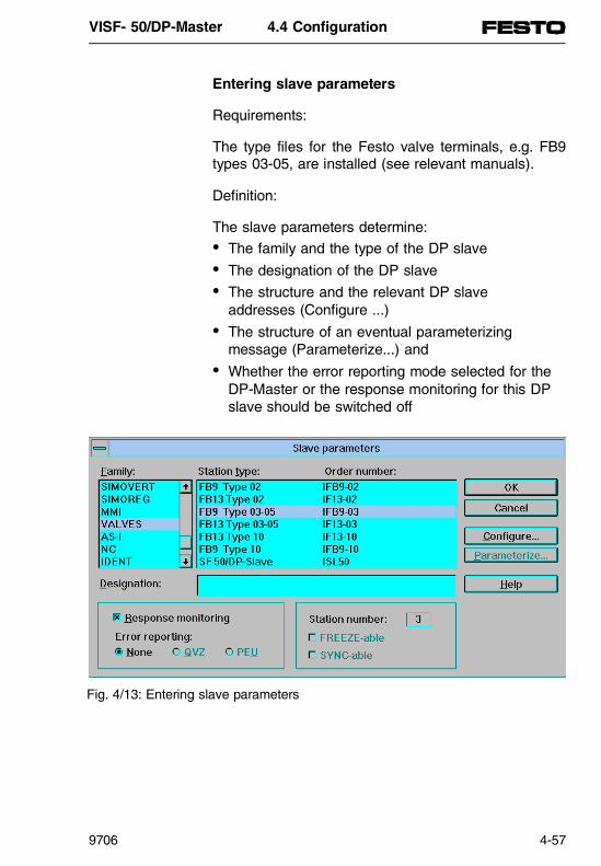
Entering slave parameters
Requirements:
The type files for the Festo valve terminals, e.g. FB9types 03-05, are installed (see relevant manuals).
Definition:
The slave parameters determine:• The family and the type of the DP slave• The designation of the DP slave• The structure and the relevant DP slave
addresses (Configure ...)• The structure of an eventual parameterizing
message (Parameterize...) and• Whether the error reporting mode selected for the
DP-Master or the response monitoring for this DPslave should be switched off
Fig. 4/13: Entering slave parameters
VISF- 50/DP-Master 4.4 Configuration
9706 4-57

Designation Significance Defaultsettings
Family Family of the remote peripheral units, e.g. valves, ET 200B, ET 200X, ... .
-
Station type With the station type the precise DP slave type is selected, e.g.recognisable by the DP slave ordernumber or stamp.
Designation Enter up to 40 characters as the namefor the remote peripheral unit.
Responsemonitoring
The response monitoring can beswitched on or off for each DP slave.
PLEASE NOTEIf the response monitoring is switchedoff, then under certain circumstancesin cases of error the outputs of thecorresponding DP slaves are notreturned to ”0”.It is therefore recommended that theresponse monitoring is only switchedoff during commissioning.
YES
Errorreporting mode
Not relevant for the SF 50/DP-Master None
Station number
With the PROFIBUS address each DPslave is assigned an individual numberon the bus:3 to 123 for SF 50/DP-Master
(Allocated PROFIBUSaddresses)
FREEZE capableSYNC capable
Not relevant for SF 50/DP-Master -
Configure ... In the ”Configure” window themagnitudes of the input and outputranges for a DP slave are set in the"Identifier“ and/or S5 addresses areassigned to these inputs and outputs.The precise data for the ”Configure”window can be found in the DP slavemanual.
-
VISF - 50/DP-Master 4.4 Configuration
4-58 9706
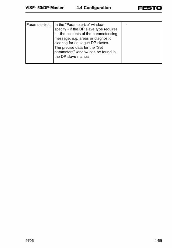
Parameterize... In the ”Parameterize” window specify - if the DP slave type requiresit - the contents of the parameterisingmessage, e.g. areas or diagnosticclearing for analogue DP slaves. The precise data for the ”Setparameters” window can be found inthe DP slave manual.
-
VISF- 50/DP-Master 4.4 Configuration
9706 4-59

Selecting slave parameters
There are various methods available for entering theslave parameters:• using the Menu bar• using the ”Slave” window• using the DP slave symbol in the user window
Fig. 4/14: Entry options for the slave parameters
VISF - 50/DP-Master 4.4 Configuration
4-60 9706

Selecting slave parameters from the menu bar
To enter slave parameters for a new DP slave,
1. Select Configure/Slave parameters and confirmthe desired PROFIBUS Address by clicking ”OK”.
For example: PROFIBUS Address #3
Result: The ”Slave parameters” window appears.
2. Fill in the slave parameters. Comprehensive expla-nations concerning the slave parameters can befound via the ”Help” button.
For example:Selection of family: "Valves“Selection of station type: "FB9 Type 03-05“
3. Confirm the slave parameters by clicking ”OK” andexit from the window.
PLEASE NOTEIt is possible to switch directly from the graphicconfiguration mode to the ”Configure” or”Parameterize” window of the DP slave.• ”Configure” window: Press down the ”Shift” key
and double-click on the DP slave symbol.• ”Parameterize” window: Press down the ”Ctrl”
key and double-click on the DP- save symbol.
VISF- 50/DP-Master 4.4 Configuration
9706 4-61

Selecting slave parameters with the "Slave“ window
To directly enter the slave parameters for a specificDP-Slave, follow the procedure:
1. Click on the symbol for the desired DP slave family in the "Slave“ window.Result: The symbol of the selected DP slave family is dragged by the mouse pointer.
2. Click with the left mouse button on the lowest posi-tion on the bus.
3. Confirm the desired slave station number by click-ing ”OK”.Result: The ”Slave parameters” window appears.
4. Fill in the slave parameters. Comprehensive expla-nations concerning the slave properties can befound in the ”Help” files.
5. Confirm the slave parameters by clicking ”OK” andexit from the window.
Fig. 4/15: Selecting DP slave family
VISF - 50/DP-Master 4.4 Configuration
4-62 9706

Selecting slave parameters with the DP slave symbol
To directly enter the slave parameters for an existingDP slave, follow the procedure:
1. Double-click in the user window on the symbol ofthe desired DP slave on the bus.Result: The specific ”Slave parameters” windowappears for the desired DP slave.
2. Fill in the slave parameters. Comprehensive expla-nations concerning the slave parameters can beobtained via the ”Help” button.
3. Confirm the slave parameters by clicking ”OK” andexit from the window.
Fig. 4/16: Selecting slave properties with the DP slave symbol
VISF- 50/DP-Master 4.4 Configuration
9706 4-63
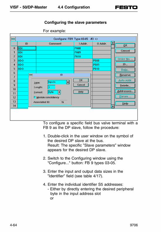
Configuring the slave parameters
For example:
To configure a specific field bus valve terminal with aFB 9 as the DP slave, follow the procedure:
1. Double-click in the user window on the symbol ofthe desired DP slave at the bus.Result: The specific ”Slave parameters” windowappears for the desired DP slave.
2. Switch to the Configuring window using the"Configure..." button: FB 9 types 03-05.
3. Enter the input and output data sizes in the ”Identifier” field (see table 4/17).
4. Enter the individual identifier S5 addresses:- Either by directly entering the desired peripheral byte in the input address slot or
VISF - 50/DP-Master 4.4 Configuration
4-64 9706

output addresses, e.g. P008 for the S5 addresses I8.0...I8.7 or- by automatically allocating addresses by marking the slots used and clicking on the "Auto address“ button.
NOTE An overview of the available and used S5 addressescan be seen by clicking on the "Addresses...“ button.
5. Confirm the "Configure: FB9 Type 03-05“ windowand "Slave parameters“ by clicking "OK“.
Configure the second field bus valve terminal FB9 inthe same manner (points 1...5). Use the PROFIBUSaddress #6 and the data in table 4/18.
Identifier Components S5-addresses Slot 0: 8 DI 8-input module I8.0...I8.7Slot 1: 8 DI 8-input module I9.0...I9.7Slot 2: 8 DI Status bits I10.4...I10.7Slot 3: 8 DO 4 double pilot valves O8.0...O8.7Slot 4: 8 DO 4 double pilot valves O9.0...O9.7Slot 5: 8 DO 4-output module O10.0...O10.3
Table 4/17: Entering for the example - valve terminals with PROFIBUS address
Identifier Components S5-addresses Slot 0: 8 DI 4-input module I11.0...I11.3
4-input module I11.4...I11.7Slot 1: 8 DI Status bits I12.4...I12.7Slot 2: 8 DO 8 monostable valves O11.0...O11.7Slot 3: 8 DO 4-output module O12.0...O12.3
Table 4/18: Entering for the example - valve terminals with PROFIBUS address #6
VISF- 50/DP-Master 4.4 Configuration
9706 4-65

NOTE
Unlike the slot-orientated distribution with theET 200U from Siemens, the addresses for the FESTOvalve terminals are entered using the basic guidelines(see the FB 9 manual).
StatusSF 50
FB9
I 1.
0 ...
1.7
FB9
I 0.
0 ...
0.7
O 1
.0 .
.. 1.
3
O0.
0 ...
0.3
I 7.
0 ...
7.7
O 0
.4 .
.. 0.
5
I 9.
0 ...
9.7
I 8.
0 ...
8.7
O 1
0.0
... 1
0.3
O 8
.0 .
.. 8.
3
I 10
.4 .
.. 10
.7
O 8
.4 .
.. 8.
7
O 9
.0 .
.. 9.
3
O 9
.4 .
.. 9.
7
I 11
.4 .
.. 11
.7
I 11
.0 .
.. 11
.3
O 1
2.0
... 1
2.3
O 1
1.0
... 1
1.1
I 12
.4 .
.. 12
.7
O 1
1.2
... 1
1.3
O 1
1.4
... 1
1.5
O 1
1.6
... 1
1.7
FB9 Slave station No. 3
FB9 Slave station No. 6
SF 50 Master station 1
Slot: 2 1 0 5 3 3 4 4
Slot: 1 0 0 3 2 2 2 2
Fig. 4/17: Address allocation of the total system
VISF - 50/DP-Master 4.4 Configuration
4-66 9706

Saving a structure configured with the COM PROFIBUS
Saving methods
There are various methods of saving the structureconfigured by COM PROFIBUS in the SF 50/DP master:
Action Menu point Reaction Where ?Save whole configuration
File\Save file orFile\Save file as...
COM PROFIBUS saves the wholebus construction in a program file.
PG
Transfer configuration ofa master systemto SF 50/DP-Master
File\Export\DP-Master...
COM PROFIBUS transfers only theconfiguration of a Master systemvia an interface component forPROFIBUS-DP to the SF 50/DPmaster
Throughthe "L2-DP“interface inthe built-inEEPROM
Save the configuration ofa master systemon the PG/PC
File\Export\ Binary file...
COM PROFIBUS saves theconfiguration of a master system ina binary file with the extension"*.2BF“.
PG
Transfer configuration ofa master systemto the SF 50/DPmaster
FESTOSF 50-Download(extra software)
FESTO SF 50-Download transfersa binary file "*.2BF“ created in theCOM PROFIBUS to the SF 50/DPmaster
Via the"PG"interface inthe built-inEEPROM
Table 4/19: Saving a structure configured with COM PROFIBUS
VISF - 50/DP-Master 4.4 Configuration
9706 4-67

Transferring a configured master system usingthe "SF 50-Download" software from Festo
Possible applications of the "SF 50-Download" software
The "SF 50-Download“ software is a simple commis-sioning aid used for transfering a configured mastersystem to the built-in EEPROM of the SF 50/DP-Master.A special advantage of this software is that no addi-tional interface components are required forPROFIBUS-DP. The transfer of the configuration datais implemented through the PG interface of the SF50/DP-Master.
SIMATICIntegrated
VISF - 50/DP-Master 4.4 Configuration
4-68 9706

Requirements for operating "SF 50-Download"
"SF 50-Download“ works in the DOS operating system or under the user interface of MS Windows.
DOS version• Operating system MS DOS (v. 3.1 or later).
To use the "SF 50-Download“ software with the DOSoperating system:• Insert the diskette enclosed with this manual into a
drive, e.g. drive A• Create a new directory with the name
FESTO\SF50M on your hard drive• Copy all files from the directory:
SF50\COMWIN20\DOWNLOAD.DOS
on the disk to the newly created directory on thehard drive.
Operation under DOS
The program can be called up at the DOS promptfrom the installation directory FESTO\SF50M as follows:
SF50M.BAT [parameter 1] [parameter 2]• Parameter 1 = DOS path+binary file name,
e.g. C:\S5_DATA\PROJECT\test• Parameter 2 = 1 for COM 1 or 2 for COM 2.
[parameter 2 is optional, default = 1].
Example:SF50M C:\S5_DATA\PROJECT\test 2
VISF - 50/DP-Master 4.4 Configuration
9706 4-69

... The binary file test.2bf is transfered via the COM2interface to the SF 50/DP-Master. The extension"2BF" is applied automatically and must not be en-tered in parameter 1.
MS Windows version• MS Windows 3.1 or higher• Minimum 386 processor
To use the "SF 50-Download“ software with the MSWindows operating system,
• Insert the disk enclosed with this manual into adrive, e.g. drive A
• Select MS Windows in the file manager• From the disk supplied, select the file
"SETUP.EXE“ in directory:
SF50\COMWIN20\DOWNLOAD.WIN
e.g. on drive A:Result: The installation program for "SF 50-Download“ is opened.
• Follow the installation instructionsResult: SF 50-Download will be installed on thePC or PG.
VISF - 50/DP-Master 4.4 Configuration
4-70 9706

Operation under MS Windows
Basic requirements:
A master system with SF 50/DP-Master has beenconfigured and saved under COM PROFIBUS.
1. Export the PROFIBUS-DP configuration within theprogram package COM PROFIBUS using theMenu commands -> FILE\EXPORT\binary file.
Insert a file name of your choice. The extension"2BF" of the file is automatically added and indi-cates that this is a binary file.Example: test.2BF
2. Change to the corresponding program group in theprogram manager, e.g. FESTO software, and
3. Double-click on the symbol for "SF 50-Download“
Result: The following program window opens:
Fig. 4/18: Fig. 4/18: "SF 50 download“ program window
VISF - 50/DP-Master 4.4 Configuration
9706 4-71

4. Select COM1 or COM2 for the interface of the PCto which the programming cable for STEP 5 is con-nected. This will normally be COM1 (Default).
5. Click on the "Download (PG) screen“. Result: A window will appear for selecting the newbinary file.
6. Selected the dessired binary file. By clicking onthe "OK" screen a DOS window is opened and the binary file is transfered to the EEPROM of the SF 50/DP master.
The following actions are thereby implemented:• Compression of the binary file
... PC installs temporary files (name.2CF)• Toggling the operating mode from RUN to STOP
... LED "RUN" = off, LED "STOP" = red• DELETION of node
... S5 Program is deleted from the RAM andEEPROM
• Transfer of configuration from PC to EEPROM... LED "BF" blinks once, LED "STOP" flickers.
If the process has been correctly implemented, anerror message appears in the DOS window.
"Parameter transfer to AG successfully concluded.Press any key to continue."
If the process has been incorrectly implemented, thefollowing error message appears on the DOS windowFollow the instructions given.
VISF - 50/DP-Master 4.4 Configuration
4-72 9706
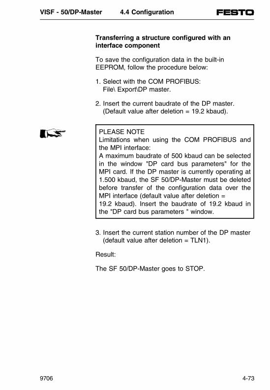
Transferring a structure configured with aninterface component
To save the configuration data in the built-in EEPROM, follow the procedure below:
1. Select with the COM PROFIBUS:File\ Export\DP master.
2. Insert the current baudrate of the DP master. (Default value after deletion = 19.2 kbaud).
PLEASE NOTELimitations when using the COM PROFIBUS andthe MPI interface: A maximum baudrate of 500 kbaud can be selectedin the window "DP card bus parameters" for theMPI card. If the DP master is currently operating at1.500 kbaud, the SF 50/DP-Master must be deletedbefore transfer of the configuration data over theMPI interface (default value after deletion = 19.2 kbaud). Insert the baudrate of 19.2 kbaud inthe "DP card bus parameters " window.
3. Insert the current station number of the DP master(default value after deletion = TLN1).
Result:
The SF 50/DP-Master goes to STOP.
VISF - 50/DP-Master 4.4 Configuration
9706 4-73

If the export of the configuration data was successful,the configuration data is compressed and saved in thebuilt-in EEPROM (STOP-LED flickers).
If the export of the configuration data was not suc-cessful, then the SF 50/DP-Master will continue towork with the old bus parameters of the EEPROM. Ifthe EEPROM is empty, default values are used.
After a STOP-RUN transfer, the DP master workswith the new configuration data.
Deleting a structure configured with theEEPROM integrated in the SF 50/DP master
The PROFIBUS-DP configuration data in the built-inEEPROM of the SF 50/DP-Master can be deleted ormodified in the following manner:• Deletion of the STEP 5 - user program by using the
STEP 5 function "Object/Blocks/Delete in the PLC/Allblocks/All modules“ in the operating mode ,,STOP“(see chapter 3.3).
• Overwriting the data by saving a new configuredstructure.
PLEASE NOTEThe standard parameter block of the SF 50/DP-Master is activated after the DELETION, and there-fore allows access to the programmer with built-ininterface components for the PROFIBUS-DP andCOM PROFIBUS on the SF 50/DP-Master.
VISF - 50/DP-Master 4.4 Configuration
4-74 9706
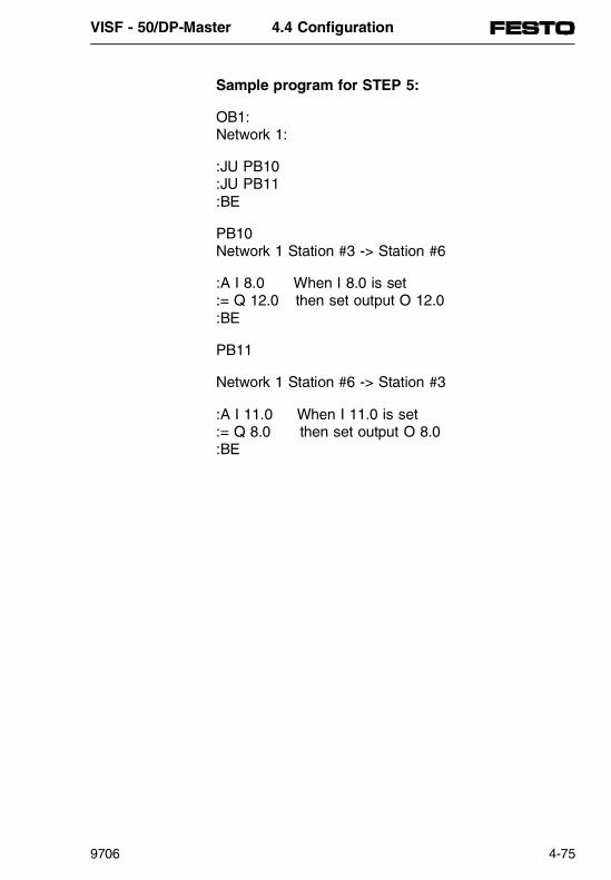
Sample program for STEP 5:
OB1:Network 1:
:JU PB10:JU PB11:BE
PB10Network 1 Station #3 -> Station #6
:A I 8.0 When I 8.0 is set:= Q 12.0 then set output O 12.0 :BE
PB11
Network 1 Station #6 -> Station #3
:A I 11.0 When I 11.0 is set:= Q 8.0 then set output O 8.0:BE
VISF - 50/DP-Master 4.4 Configuration
9706 4-75

VISF - 50/DP-Master 4.4 Configuration
4-76 9706

4.5 DIAGNOSIS
PN
368
618
VISF - 50/DP-Master 4.5 Diagnosis
9706 4-77

Contents
4.5 DIAGNOSIS
Fault diagnosis in the PROFIBUS-DP system......................................4-79Fault diagnosis using the display elements ................................................4-79Diagnosis options in STEP 5-Control program of the SF 50 ...........................4-81Station diagnosis ...............................................4-83Booting the SF 50/DP-Master on the bus..........................................................4-87Requirements for booting up .............................4-87Booting up of the SF 50/DP-Master ..................4-88Default parameter block ....................................4-89Message in the operating system data .............4-89How the PROFIBUS-DP system functions ................................................4-90Current supply / system recovery / RUN<->STOP....................................................4-90Reactions depending on response monitoring..4-91Reaction times in the PROFIBUS-DP system......................................4-93
VISF - 50/DP-Master 4.5 Diagnosis
4-78 9706

Fault diagnosis in the PROFIBUS-DP system
This chapter contains instructions on fault determina-tion through the display elements of the SF 50. In ad-dition, fault diagnosis using a STEP 5 program is de-scribed.
Fault diagnosis with the display elements
The display elements on the front panel of the SF 50provide the first information concerning the type offault. The following figure shows the significance ofthe fault display elements.
SIMATICIntegrated
RUN BF
STOP
SIEMENS
PG
L2-DP
BF LED display(BUS FAULT = red)
DP masterinterface forPROFIBUS-DP
Fig. 4/19: Fault display elements of the SF 50
VISF - 50/DP-Master 4.5 Diagnosis
9706 4-79
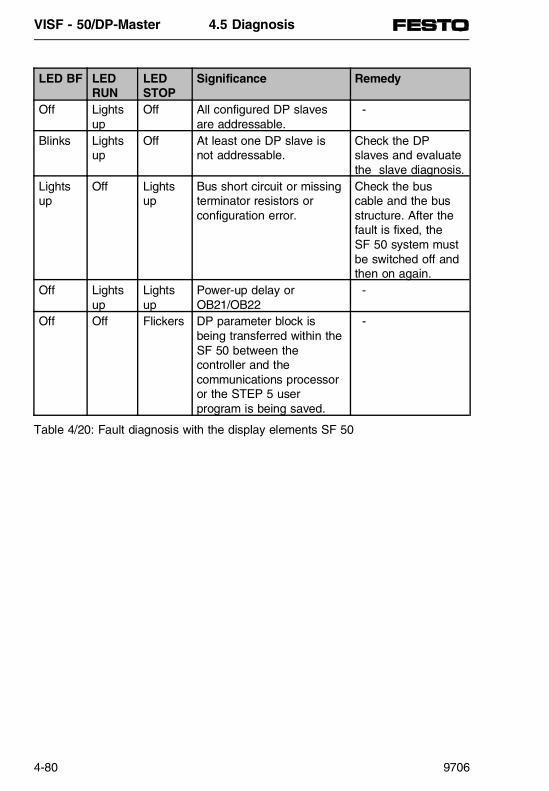
LED BF LEDRUN
LEDSTOP
Significance Remedy
Off Lightsup
Off All configured DP slavesare addressable.
-
Blinks Lightsup
Off At least one DP slave isnot addressable.
Check the DPslaves and evaluatethe slave diagnosis.
Lightsup
Off Lightsup
Bus short circuit or missingterminator resistors or configuration error.
Check the buscable and the busstructure. After thefault is fixed, the SF 50 system mustbe switched off andthen on again.
Off Lightsup
Lightsup
Power-up delay orOB21/OB22
-
Off Off Flickers DP parameter block isbeing transferred within theSF 50 between thecontroller and thecommunications processoror the STEP 5 userprogram is being saved.
-
Table 4/20: Fault diagnosis with the display elements SF 50
VISF - 50/DP-Master 4.5 Diagnosis
4-80 9706

Diagnosis options in the STEP 5 control program of the SF 50
It is possible to call up and evaluate specific diagnosismessages in the control program.
• The save stations automatically "recognise" anyfaults and transfer the diagnosis data to the master interface component of the SF 50. The typeof message enables the SF 50 to distinguish be-tween diagnosis data and input/output data.
It is possible to systematically localise and evaluate afault by the following methods:
Diagnosis Significance Interrogations in STEP 5"Overview diagnosis" Covers all stations, where
diagnosis data existIW126
"Station diagnosis" Evaluates the type of faultdetected in accordance withEN 50170 (PROFIBUS-DP)
Function module S_DIAG(FB230)
Table 4/21: Diagnosis options in STEP 5
SIMATICIntegrated
VISF - 50/DP-Master 4.5 Diagnosis
9706 4-81
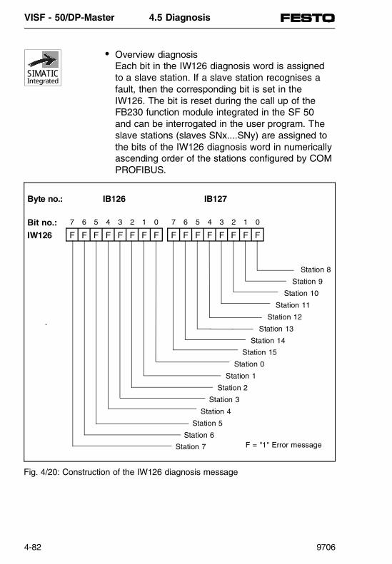
• Overview diagnosisEach bit in the IW126 diagnosis word is assignedto a slave station. If a slave station recognises afault, then the corresponding bit is set in theIW126. The bit is reset during the call up of theFB230 function module integrated in the SF 50and can be interrogated in the user program. Theslave stations (slaves SNx....SNy) are assigned tothe bits of the IW126 diagnosis word in numericallyascending order of the stations configured by COMPROFIBUS.
F = "1" Error message
Fig. 4/20: Construction of the IW126 diagnosis message
SIMATICIntegrated
Byte no.: IB126 IB127
Bit no.: 7 6 5 4 3 2 1 0 7 6 5 4 3 2 1 0
IW126 F F F F F F F F F F F F F F F F
Station 8
Station 9
Station 10
Station 11
Station 12
Station 13
Station 14
Station 15
Station 0
Station 1
Station 2
Station 3
Station 4
Station 5
Station 6
Station 7
VISF - 50/DP-Master 4.5 Diagnosis
4-82 9706

Example:
Slave stations: Slave number (SN) 5 / 6 / 10 / 12 / 40 / 50 / 77 / 88 /120 / 123
Slave Bit Physical station
SN 5 ⇒ I126.0 ⇒ Station 0SN 6 ⇒ I126.1 ⇒ Station 1
SN 10 ⇒ I126.2 ⇒ Station 2SN 12 ⇒ I126.3 ⇒ Station 3SN 40 ⇒ I126.4 ⇒ Station 4
SN 50 ⇒ I126.5 ⇒ Station 5SN 77 ⇒ I126.6 ⇒ Station 6
SN 88 ⇒ I126.7 ⇒ Station 7SN 120 ⇒ I127.0 ⇒ Station 8SN 123 ⇒ I127.1 ⇒ Station 9
Station diagnosis
Station diagnosis is called up by the integrated func-tion module S_DIAG (FB230) in the master interfacecomponent of the SF 50 and is made transparent tothe user program by means of an assigned datablock.
SIMATICIntegrated
DW Significance DL Significance DR0 Number of the slave station
where diagnosis data existNumber of the subsequentdiagnosis bytes
1 Station status 1 Station status 22 Station status 3 Master station number3 Manufacturer’s identification
4...16 Further slave-specific diagnosis (unit-, identifier- or channel-relateddiagnosis, always related to the DP slave)
Table 4/22: Structure of the slave diagnosis
VISF - 50/DP-Master 4.5 Diagnosis
9706 4-83
• An FB230 is assigned to each station, a data blockcan be used for many stations.
• The FB230 is specifically called up in the dia-gnosis overview (IW126) by the bit assigned to thestation.
The function module S_DIAG reads the diagnosisdata of the parameterised PROFIBUS-DP slave sta-tion and stores it in the parameterised data blockS_DIAG. Up to 34 bytes of diagnosis data (as speci-fied in PROFIBUS-DP - EN 50170, part 3) can bestored in the data block designated by the transferparameter, starting with the data word which has alsobeen specified by the transfer parameter.
PLEASE NOTE This function module is only relevant for an SB 50with field bus expansion, namely the SF 50.
The data block used for filling the diagnosis data mustbe compiled in sufficient length before calling up thefunction module S_DIAG. The minimum length of thedata block must be based on the maximum length ofthe diagnosis information of 17 data words (34 bytes).It is useful to check for the existence of a diagnosismessage by interrogating the station diagnosis bitsbefore calling up the FB230 function module.
VISF - 50/DP-Master 4.5 Diagnosis
4-84 9706

Parameter Significance Type AllocationS_NR Station no. or
Slave numberD KY KY=x,y
x=0 Direct parametrisationy=0...15 Station or slave No.y>18 ... 255
First station with diagnosisx<>0 Indirect parameterisationy with indirect parameterisation:
irrelevant
DBNR Definition oftarget area
D KY KY=x,y
Direct parameterisation
x=2...255 data block numbery=0...255 data word number
The diagnosis data is filed from thedata word of the parameterised DBnumber thus stated
Indirect parameterisation
x=2...255 data block numbery=0...255 data word number
The station number and target areaparameters are filed from the dataword of the data block stated. The highbyte of the station number parametermust have the value zero.
Table 4/23: Call-up and parameterisation of the FB230
VISF - 50/DP-Master 4.5 Diagnosis
9706 4-85
Example::A I 126.0 SN 5 damaged:JC FB230 Call up of the diagnosis-
block S_DIAGName :S_DIAGS_NR : KY0,0 Direct parametrisation,
Station 0 (e.g. slave No. #3)on the bus
DBNR : KY230,0 diagnosis data will be filed in DB230 from DW0(36 bytes)
:A I 126.1 SN 6 damaged :JC FB230 Call-up of the diagnosis
block S_DIAG Name :S_DIAGS_NR : KY0,1 Direct parametrisation,
station 1 (e.g. slave No. #6)on the bus
DBNR : KY230,20 diagnosis data will be filed in DB230 from DW20 (36 bytes)
VISF - 50/DP-Master 4.5 Diagnosis
4-86 9706
Booting up the SF 50/DP-Master on the bus
Requirements for booting up
It is assumed that:
• The SF 50/DP-Master has been started up withoutusing the DP master interface (see chapter 3).
• The DP slaves have been wired up.• All DP slaves and DP-Master have been
connected to the bus cable.• The power supply of the DP slaves has been
switched on.• The DP slaves - where possible - have been
switched to RUN.
VISF - 50/DP-Master 4.5 Diagnosis
9706 4-87

Booting up the SF 50/DP-Master
Stromversorgung für SF 50einschalten
Betriebsartenschalter auf STOP schaltenEin-/Ausschalter am SF 50
DP-Parametersatzauf EEPROMvorhanden?
DP-Parametersatz wird in das SF 50übertragen (LED BF flimmert)
projektierte DP-Slaves werden in Übersichtsdiagnose eingetragen
Betriebsart von STOP in RUNschalten (AG-Neustart)
Löschen des Prozeßabbildes, der DP-Daten, der nichtremanenten Zeiten,
Zähler, Merker im SF 50
Default-Parametersatzwird eingestellt
(siehe nächste Seite)
Betriebsart von STOP in RUNschalten (AG-Neustart)
Löschen des Prozeßabbildes, der DP-Daten, der nichtremanenten Zeiten,
Zähler, Merker im SF 50
LED BF erlischt(kein DP-Master-Betrieb)
Nein
Ja
SF 50 nimmt DP-Slaves in den Bus auf
SF 50 trägt ansprechbare DP-Slavesaus Übersichtsdiagnose aus
Haben alle DP-Slavesquittiert?
Nein
JaHochlaufverzögerung
abgelaufen? Nein
Ja
LED BF erlischt; Datenaustauschzwischen SF 50 und dezentraler
Peripherie kann stattfinden
Switch on power supply for SF 50
Set operating mode to STOP
Is the DP parameter block available on EEPROM?
No
DP parameter block transfered to SF 50(BF LED flickers)
Configured DP slaves are entered into diagnosis overview
Default parameter block is accepted (see next page)
Switch operating mode from STOP toRUN (automation device new start)
Switch operating mode from STOP to RUN (automation device new start)
Delete process image, DP data, non-remanent periods, counters, flags in the SF 50
Delete process image, DP data, non-retentive periods, counters, flags in the SF 50
SF 50 accepts the DP slaves from the diagnosis summary
BF LED turns off (no DP master operation)
SF 50 detects addressable DP slavesfrom the diagnosis overview
Have all DP slaves quit ?
No
BF LED turns off, data exchange between the SF 50 and the remote peripherals can occur
NoYes
Yes
Yes
Booting up delay expired ?
Fig. 4/21: Booting up the SF 50/DP-Master
VISF - 50/DP-Master 4.5 Diagnosis
4-88 9706

Default parameter block
The default parameter block is accepted by the SF 50/DP-Master, if there are no DP parameter blocksavailable on the integrated EEPRO M (see figure 4/21).
The default parameter block contains:• Station number = 1• Baud rate = 19.2 kbaud• No DP slave parameterised• Highest active station number = 126
Reporting in operating system data
The system data word 17 of the SF 50/DP-Master (ab-solute address: 5D22H) contains the following infor-mation concerning the DP parameter block:• 00H = Default parameter block is valid• 01H = User parameter block is valid
The allocation of the remaining systems data can befound in chapter 3.5
VISF - 50/DP-Master 4.5 Diagnosis
9706 4-89

How the PROFIBUS-DP system works
Power supply / mains powerrestoration / RUN<->STOP
The following chapter shows how the PROFIBUS-DPsystem - arranged according to specific events - be-haves in relation to the SF 50/DP-Master:
Action Require-ments
SF 50/DP-Master DP-Slave
First timepowersupply isturned on
STOP It is not possible to access the inputs/outputs of the remote peripherals.
Outputs are set to”0”
STOP ->RUN
Diagnosis data, DP inputs andoutputs are deleted. Diagnosis data and DP inputs areupdated. DP outputs are written.DP outputs are initialized (if the OB21 start up has been programmed).
Inputs are read. Outputs areupdated.
Mainspowerrestora-tion
RUN Diagnosis data, DP inputs andoutputs are deleted.Diagnosis data and DP inputs areupdated. DP outputs are written.
Inputs are read. Outputs are updated.
Bus running
RUN ->STOP
It is not possible to access theinputs/outputs of the remoteperipherals.
Outputs are set to”0”
STOP ->RUN
It is possible to access the inputs/outputs of the remote peripherals.
Inputs are read.Outputs areupdated.
Table 4/23: Reactions of the SF 50/DP-Master
VISF - 50/DP-Master 4.5 Diagnosis
4-90 9706

Reactions in relation to response monitoring
The following table shows the reactions producedwhen bus communication to one or more DP slaves isinterrupted or when a DP slave fails.
Failed DP slaves:responsemonitoring
Reaction of the SF 50/DP-Master
Reaction of the SF 50/DP-Master and thefailed DP slaves
Reaction of the SF 50/DP-Masterand the remainingDP slaves
No SF 50/DP-Master staysin RUN mode
SF 50/DP-Master:Inputs are set to ”0”.Outputs are updatedinternallyDP-Slave: Outputs are frozen.
SF 50/DP-Master: Inputs and outputsare further updated. DP slaves: Outputs are furtherupdated.
Yes SF 50/DP-Master staysin RUN mode
SF 50/DP-Master:Inputs are set to ”0”. Outputs are updatedinternally. DP slave: Outputs are set to ”0”after the end of the ad-dress monitoring period.
SF 50/DP-Master:Inputs and outputsare further updated.
DP slaves: Outputs are furtherupdated.
Table 4/24: Reactions in relation to response monitoring
VISF - 50/DP-Master 4.5 Diagnosis
9706 4-91

VISF - 50/DP-Master 4.5 Diagnosis
4-92 9706

Reaction times in the system
Figure 4/22 shows the data paths and table 4/25shows the delay times between the SF 50/DP-Masterand the input and output modules of the remote pe-ripherals.
1 Through the user program in the PLC
2 Between the CPU and Master interface component of the SF50/DP-Master
3 Via the PROFIBUS-DP between the Master inter- face component and the DP slave
4 Within the slave interface component
5 Between the slave interface component and the valves and/or input/output components
6 Within the input/output components
7 Via the PROFIBUS-DP between the DP slaves
1
2
3
4
5
6 6
57
SF 50 master station Slave stations
PROFIBUS-DP
Fig. 4/22: Data paths in the remote peripheral system with SF 50
VISF - 50/DP-Master 4.5 Diagnosis
9706 4-93

Delay time ... Relevance... through the user program in the PLC Dependent on the user program... between the PLC and field bus master Only important with high baud
rates and word type access toconsistent data (e.g. analogue I/O)
... via the PROFIBUS-DP Important with high baud rates andcomprehensive data messages
... within the FB 9 through data messages Dependent on the number of out-put bytes (coming from the FB 9)
... between the FB 9 and valves, or I/O components (via the peripheral bus)
Dependent on the number ofvalves, or I/O components
... the input/output modules Dependent on the unit
... from FB 9 to ET 200 Negligible
Table 4/25: Summary of the delay times
VISF - 50/DP-Master 4.5 Diagnosis
4-94 9706

Programmable valve terminalswith
SB 50 / SF 50 control block
Part 5: SF 50 / DP slave system description
PN
368
619
9706

PN 368 619 is shown in: Manual 174 826
Manual 174 827
Manual 174 828
9706

Chapter summary
The manual consists of various sections compiled ac-cording to the equipment used for the valve terminal:
Part 1 Installation guidelinescontains information irrespective of the type of valveterminal or node selected.
Part 2a Valve terminal type 02System description of valve terminal type 02 containsall necessary information specifically required for thistype of terminal.
Part 2b Valve terminal type 03System description of valve terminal type 03 containsall necessary information specifically required for thistype of terminal.
Part 3 System description for SB 50contains all PLC-specific information irrespective ofvalve terminal type.
Part 4 System description for SF 50 as Mastercontains additional information that must be observedwhen using the PROFIBUS-DP.
Part 5 System description for SF 50 as DP-Slavecontains additional information that must be observedwhen using the SF 50/DP slave (SL 50).
Part 6 Appendixcontains additional information concerning commandsets, abbreviations, accessories, literature, etc.
PN
368
619
VISF - 50/DP Slave
9706 5-I

Notes
___________________________________________
___________________________________________
___________________________________________
___________________________________________
___________________________________________
___________________________________________
___________________________________________
___________________________________________
___________________________________________
___________________________________________
___________________________________________
___________________________________________
___________________________________________
___________________________________________
___________________________________________
___________________________________________
___________________________________________
___________________________________________
___________________________________________
___________________________________________
___________________________________________
___________________________________________
VISF - 50/DP Slave
5-II 9706

Contents
5.1 System description..........................................................................5-3SF 50/DP-Slave with PROFIBUS-DP interface.................................5-3Application possibilities using the SF 50/DP-Slave with PROFIBUS-DP interface....................................................................5-4Structure and operating mode of the SF 50/DP-Slave .....................5-5Display and operating elements ........................................................5-6Pin assignment of the PROFIBUS-DP interface ...............................5-6
5.2 Data transfer via the PROFIBUS-DP interface of the SF 50/DP-Slave.............................................. ......5-9
Data transfer properties with the SF 50 as a DP slave ....................5-9Principal operating mode of data transfer .......................................5-10Structure of the extended peripheral area of the SF 50/DP-Slave............... ................................................................5-12Access to send and receive data ....................................................5-14Access to user-specific parameterization data................................5-16
5.3 Specifying the configuration of the SF 50/DP-Slave with COM ET 200 in the DP-Master..............................................5-21
Operation of COM ET 200, v. 4.x....................................................5-21Operation of COM ET 200 Windows...............................................5-24Entering properties of the send and receive data using decimal code configuration bytes ....................................................5-27Device master file................ ............................................................5-29Determining the user-specific parameterization data inthe parameter message of the DP-Master ......................................5-30
PN
368
619
VISF - 50/DP Slave Contents
9706 5-III

5.4 Parameterising the PROFIBUS-DP interface of the SF 50/DP-Slave in DB1... ...............................................................5-35
Parameterization process... .............................................................5-36DB1 parameters for the SF 50/DP-Slave with PROFIBUS-DP interface..........................................................5-37Entering parameters in the DB1 and in the SF 50/DP-Slave .........5-39DB1 parameterization faults for PROFIBUS-DP interface ..............5-41
5.5 Sample program for the SF 50 as a PROFIBUS-DP slave .......5-45 Cyclic program for the SF 50 as DP slave ....................................5-46
5.6 Commissioning of the SF 50/DP-Slave .......................................5-51Starting-up behaviour of the SF 50/DP-Slave.................................5-51Starting-up PROFIBUS-DP..............................................................5-52Starting-up the SF 50/DP-Slave with STOP-RUN transition...........5-52STOP-RUN transition of the SF 50/DP-Slave without DB1-changes in the parameter block ”DPS:” ..................................5-52STOP-RUN transition of the SF 50/DP-Slave with DB1 changes in the ”DPS” parameter block...................................5-52STOP status of the SF 50/DP-Slave...............................................5-53Instructions for the configuration and installation of the SF 50/DP-Slave.............. ...........................................................5-54Requirements for commissioning the SF 50/DP-Slaveas a PROFIBUS-DP slave...............................................................5-56Starting sequence of the SF 50/DP-Slave as PROFIBUS-DP slave.......................................................................5-58Working steps for commissioning the SF 50/DP-Slave as a PROFIBUS-DP slave...............................................................5-58
VISF - 50/DP Slave Contents
5-IV 9706

5.7 Testing and diagnosis....... ............................................................5-63Summary ot testing and diagnosis options .....................................5-64
5.7.1 Fault diagnosis in the user program of the DP-Master..........5-65General remarks concering diagnosis .............................................5-65Special notes concerning diagnosis requirements in ”Page frame operation” ................................................................5-66General construction of diagnosis for SF 50/DP-Slave...................5-67Station status and station number of the DP-Master ......................5-68Requesting station status 3 and station number of the DP-Master..............................................................................5-69Requesting manufacturer’s indentification.......................................5-69Requesting signs of life from the control processor in the SF 50/DP-Slave........................ .......................................................5-70STOP causes in SF 50/DP-Slave....................................................5-71Requesting STOP causes ...............................................................5-71User-specific diagnosis ....................................................................5-72Transferring user-specific diagnosis to DP-Master .........................5-72Evaluation..................... ...................................................................5-72User-specific diagnosis ....................................................................5-73
5.7.2 Function of the BF LED on the SF 50/DP-Slave......................5-74
5.7.3 Fault diagnosis in the user program of the SF 50/DP-Slave.. ...............................................................5-76
”Status reports" diagnosis byte........................................................5-78”Error reports” diagnosis byte ..........................................................5-79
5.7.4 Failure behaviour of the SF 50/DP-Slave .................................5-80Lifesigns of the control processor in the SF 50/DP-Slave............... ................................................................5-80DP slave operation monitoring with the DP-Master ........................5-81
VISF - 50/DP Slave Contents
9706 5-V

VISF - 50/DP Slave Contents
5-VI 9706

5.1 SYSTEM SUMMARY
PN
368
619
VISF - 50/DP Slave 5.1 System summary
9706 5-1

Contents
5.1 System description..........................................................................5-3SF 50/DP-Slave with PROFIBUS-DP interface.................................5-3Application possibilities using the SF 50/DP-Slave with PROFIBUS-DP interface.................... .......................................5-4Construction and operating mode of the SF 50/DP-Slave................5-5Display and operating elements ........................................................5-6Pin assignment of the PROFIBUS-DP interface ...............................5-6
VISF - 50/DP Slave 5.1 System summary
5-2 9706
5.1 System description
This chapter contains information concerning: • the PROFIBUS-DP in general, • Performance characteristics and features that are
offered by the PROFIBUS-DP interface of the SF 50/DP-Slave and
• Equipment with which the SF 50/DP-Slave cancommunicate as a PROFIBUS-DP bus slave.
SF 50/DP-Slave with PROFIBUS-DP interface
The PROFIBUS-DP interface of the SF 50/DP-Slaveoffers the following performance characteristics:• The SF 50/DP-Slave can in general only be a
DP slave on the PROFIBUS-DP. • The SF 50/DP-Slave is a DP Standard slave. This
means that the PROFIBUS-DP interface compliesfully with the PROFIBUS-DP standard (DIN 19245, part 3).
The PROFIBUS-DP interface of the SF 50/DP-Slaveoffers the following features:• Intelligent pre-processing is possible. • The connection of the SF 50/DP-Slave to the
PROFIBUS-DP does not require any knowledge ofcommunication mechanisms.
VISF - 50/DP Slave 5.1 System summary
9706 5-3

Application possibilities using the SF 50/DP-Slavewith PROFIBUS-DP interface
The following figure shows a typical structure of aPROFIBUS-DP. DP-Master is a PLC with PROFIBUS-DP-Master; DP slaves are the SF 50/DP-Slave, S5-95U as DP slave and other field units.
The structure guidelines for the system are described in chapter 4.
The SF 50/DP-Slave can communicate with the following equipment via the PROFIBUS-DP:
COMET200
SI E MENS
R UN
ST OP
BF
2 4 VDC FU SE
L 2 -D P
PG
1
0
RU N
ST OP
RU N
ST OP
CO PY
L +
M
2 4 V DC
P G
6 ES5 0 9 5 - 8M A0 1
1 2 34 5 6
1
2
3
4
6
8
910
5
7
11
12
13
14
1 5
1 6
17
18
20
21
25
26
27
19
22
23
24
28
29
3031
32
34
35
36
37
38
40
39
33
S I E M E N SO U T1 6 x 24 D C0 ,5 A
IN16 x 24 D C
Ba tte ry3 ,4 V8 5 0m Ah
Ba t te r yO F FL O W
S I M A T I C S 5 - 9 5 U
ANALOG /IN/OUT8 x 0 . . + 10 V1 x 0 . . + 10 V 0 .. +20 mA
2 4 V D CC O U N T E R5 /2 k H zINT ER RU PT
D IG IT AL
L+32.0.1.2.3.4.5.6.7ML+33.0.1.2.3.4.5.6.7M
L+32.0.1.2.3.4.5.6.7ML+33.0.1.2.3.4.5.6.7M
PG / PC
Higher-order control unit withPROFIBUS-DP-Master
Further field units
SF 50/DP-Slave
S5-95U
Fig. 5/1: Equipment configuration
VISF - 50/DP Slave 5.1 System summary
5-4 9706

Structure and operating mode of the SF 50/DP-Slave
This chapter contains information for the structure andoperating mode of the SF 50/DP-Slave. The followingfigure shows the display elements and interfaces ofthe control block:
Devices / component Essential software for commissioning / for testing
Programmable valve terminal SF 50with PROFIBUS-DP-Master (see chapter 4.x)
COM ET 200 (v. 4.0 or later)
Master interface component IM 308-Bversion 5 (applicable for S5-115U/ H...S5-155U/H)
COM ET 200 (v. 4.0 or later)
AG S5-95U / DP-Master COM ET200 for WINDOWS (v. 2.x or later)Master interface component IM 308-C COM ET200 for WINDOWS (v. 1.x or later)Other automation tools with integrated DP-Master interfacePC with communications processor CP 5410 S5-DOS/ST
COM ET 200 (v. 4.0 or later)
Table 5/1: Communications partners for SF 50/DP-Slave
SIEMENS
RUN BF
L2-DP
PG
STOP
BF LED Display(BUS FAULT = red)
Interface forPROFIBUS-DP
Fig. 5/2: Display elements of the SF 50/DP-Slave
VISF - 50/DP Slave 5.1 System summary
9706 5-5

Display and operating elements
Like the SB 50, the SF 50/DP-Slave has no operatingelements. The field bus interface is supplied withpower by the power supply of the valve terminal andis switched to RUN or STOP through the programmerand the PLC function "START/STOP" simultaneouslywith the SB 50.
PIN allocation of the PROFIBUS-DP interface
LED display SignificanceRUN - PLC in "RUN" or "START" operating modeSTOP - SF 50 in "STOP" or "START" operating mode
- Error display of the SF 50 - Program and data are being copied from the EEPROM-> RAM
BF - Communication via the field bus is interrupted or has not yet been established
Table 5/2: LED display of the SF 50
View PIN-No.
Signal Name Designation
123456789
PE-RxD / TxD-PRTSM5V2P5V2-RxD / TxD-N-
Protective earth-Data line BRequest to sendData earthSupply Plus-Data line A-
Table 5/3: Pin assignment of the PROFIBUS-DP interface
5
4
3
2
1
9
8
7
6
VISF - 50/DP Slave 5.1 System summary
5-6 9706

5.2 DATA TRANSFER
PN
368
619
VISF - 50/DP slave 5.2 Data transfer
9706 5-7
Contents
5.2 Data transfer via the PROFIBUS-DP interface of the SF 50/DP-Slave .....................................................5-9
Data transfer properties with the SF 50 as a DP slave ....................5-9Principal operating mode of data transfer .......................................5-10Structure of the extended peripheral areas of the SF 50/DP-Slave............... ................................................................5-12Access to transmitting and receiving data ......................................5-14Access to user-specific parameterization data................................5-16
VISF - 50/DP slave 5.2 Data transfer
5-8 9706

5.2 Data transfer via the PROFIBUS-DP interface of the SF 50/DP-Slave
This chapter contains information concerning: • How the data transfer of the SF 50/DP-Slave
works in principle,• how the extended peripheral areas of the
SF 50/DP-Slave are structured and • how to access the transmitting and receiving data
in the user program.
Data transfer properties with the SF 50 as a DP slave• The SF 50/DP-Slave can only be a DP slave on
the PROFIBUS-DP. The SF 50/DP-Slave preparesdata for a DP-Master and can receive and processdata from this DP-Master.
• The baud rate is determined in the DP-Master. TheSF 50/DP-Slave accepts the following baud rates: 9.6 kbaud; 19.2 kbaud; 93.75 kbaud; 187.5 kbaud; 500 kbaud and 1500 kbaud.
• The SF 50/DP-Slave can prepare a maximum of32 bytes of data for collection by the PROFIBUS-DP and receive a maximum of 32 bytes of data viathe PROFIBUS-DP. The send and receive dataare automatically prepared by the communicationsprocessor in the SF 50/DP-Slave, i.e. without theuser program.
• There are extended peripheral areas (for DP only)available for transmitting and receiving data. Theuser defines and sets out the extended peripheralareas with load and transfer operations from theuser program.
VISF - 50/DP slave 5.2 Data transfer
9706 5-9
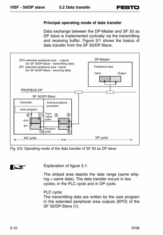
Principal operating mode of data transfer
Data exchange between the DP-Master and SF 50 asDP slave is implemented cyclically via the transmittingand receiving buffer. Figure 5/1 shows the basics ofdata transfer from the SF 50/DP-Slave.
Explanation of figure 3.1:
The striped area depicts the data range (same strip-ing = same data). The data transfer occurs in two cycles; in the PLC cycle and in DP cycle.
PLC cycle: The transmitting data are written by the user programin the extended peripheral area outputs (EPO) of theSF 50/DP-Slave (1).
Peripheral area
Input Output
PROFIBUS-DP
SF 50/DP-Slave
DP cycleAG cycle
User program
Controller Communicationsprocessor
EPO
EPI
Trans-mittingbuffer
Reception buffer
DP-MasterEPO extended peripheral area - outputs (for SF 50/DP-Slave - transmitting data)EPI extended peripheral area - inputs (for SF 50/DP-Slave - receiving data)
Fig. 5/3: Operating mode of the data transfer of SF 50 as DP slave
VISF - 50/DP slave 5.2 Data transfer
5-10 9706

At the cycle control point the communications proces-sor copies the transmitting data from the EPO into theDP transmitting buffer (2). At the same time the com-munications processor copies the receiving data inthe extended peripheral area inputs (EPI) (3). The re-ceiving data stored in the EPI can be evaluated bythe user program (4). Data exchange between thecontroller and communications processor occurs atthe cycle control point.
DP cycle: The DP-Master sends data to the SF 50/DP-Slavewhich are stored in the receiving buffer of the commu-nications processor of the SF 50/DP-Slave (5). At the same time the transmitting data of the SF 50/DP-Slave are collected from the DP-Master (6).The data exchange between the DP-Master and DPslave occurs cyclically via the bus, irrespective of thecycle control point of the SF 50/DP-Slave.
VISF - 50/DP slave 5.2 Data transfer
9706 5-11
Structure of the extended peripheral area of the SF 50/DP-Slave
There are extended peripheral areas available in theSF 50/DP-Slave for the transmitting/receiving of datavia the PROFIBUS-DP. The extended peripheral areas of the SF 50/DP-Slave are connected in the SF 50/DP-Slave to the areas of the process image:• The process image of the inputs assigns the
addresses 0.0 ... 127.7 • The extended peripheral area - inputs (EPI) as-
signs the addresses 128.0 ... 255.7 • The process image of the outputs assigns the
addresses 0.0 ... 127.7 • The extended peripheral area - outputs (EPO) as-
signs the addresses 128.0 ... 255.7
Please note that the extended peripheral areas areonly available on an SF 50/DP-Slave fitted with aPROFIBUS-DP interface. No units in the extended pe-ripheral areas of the SF 50/DP-Slave are address-able. The extended peripheral areas are used solelyfor storing DP data in the SF 50/DP-Slave.
PLEASE NOTEPlease note that extended peripheral areas are onlyavailable with the SF 50/DP-Slave. No device modules in the extended peripheral areas of the SF 50/DP-Slave are addressable. The extended pe-ripheral areas are used solely for storing DP data inthe SF 50/DP-Slave.
Table 5/4 gives the precise structure of the extendedperipheral areas in the SF 50/DP-Slave. The slaveaddresses in EPI are read-only access, but the ad-dresses in EPO can be accessed via the user pro-gram.
VISF - 50/DP slave 5.2 Data transfer
5-12 9706

The user defines and sets out the extended peripheralareas with load and transfer operations from the userprogram.
Absoluteaddress
Addressin EPI
Allocation
5700H
:571FH.
128.0:
159.7
Receiving data(sent from DP-Master)
5720H
:5738H
160.0:
184.7
User-specificparameterization data (sentfrom DP-Master)
5739H
:577DH
185.0:
253.7Empty
577EH
:577FH
254.0:
255.7
Diagnosis bytes "Status reports" and "Errorreports"
Addressin EPO
5780H
:579FH
128.0:
159.7
Transmitting data(prepared for DP-Master)
57A0H
:57F9H
160.0:
249.7Empty
57FAH
:57FFH
250.0:
255.7
User-specific diagnosis bytes
Table 5/4: Structure of the extended peripheral area of theSF 50/DP-Slave
VISF - 50/DP slave 5.2 Data transfer
9706 5-13

Access to transmitting and receiving data
The transmitting data must be recorded in the userprogram of the SF 50/DP-Slave with the transfer operations in the extended peripheral area - outputs(EPO).
The following operations, value ranges and dataranges can be used:
Requirements for access to the receiving data:• In the diagnosis byte ”status messages” Bit 5=1,
i.e. commissioning through the DP-Master has occured and
• in the diagnosis byte ”Error messages” Bit 4=0,i.e. the receiving data in the SF 50/DP-Slave isvalid.
e.g.: Loading fromuser program
Transferring in EPO
Example Explanation
Sending small amounts of data (ca. 1...8 Bytes) can be done through the byte or word-wise access in the user program:
L IB/QB/IW/QW/ PY/PWI/FY/FW/ DL/DR/DW
TPY128...159/TPW128 ...158
LIB5TPY140
The input byte 5 istransferred to theperipheral byte 140 inEPO
Access via the TNB operation*) in the user program is suitable for sending lotsof data (max. 32 bytes):
TNB 1...32 (Bytes)
(Initial address inEPO is 5780H
LKH61FKH579CTNB20
20 Bytes from the flagbyte 63 (MB63...MB44) aretransferred to the EPO from peripheral byte 156 (PY156...PY137).
*) Transfering a data block in bytes (see chapter 3.7)
Table 5/5: Access to transmitting data in the user program
VISF - 50/DP slave 5.2 Data transfer
5-14 9706

The receiving data stored in the extended peripheralarea - inputs (EPI) must be linked with the load operations in the user program of the SF 50/DP-Slave.
The following operations, value ranges and dataranges can be used:
A detailed program sample using an SF 50/DP-Slaveas a DP slave can be found in chapter 5.5.
Loading fromEPI
Transferring in theuser program
Example Explanation
Reception of small amounts of data (ca. 1...8 Bytes) can be done through the byte or word-wise access in the user program:
LPY128...159/LPW128...158
TIB/QB/IW/QW/PY/PW/FY/FW/DL/DR/DW
LPY130TFY200
The peripheral byte 130in EPI is transferred tothe flag byte 200.
Access via the TNB operation*) in the user program is suitable for receivinglots of data (max. 32 bytes):
TNB1...32 (Bytes) LKH571DLKH61E6TNB30
30 Bytes are transferredfrom the EPI fromperipheral byte 157 (PY157...PY128) to thearea from the flag byte230 (FY230...FY201).
*) Transferring a data block in bytes
Table 5/6: Access to receiving data in the user program
VISF - 50/DP slave 5.2 Data transfer
9706 5-15

Access to user-specific parameterization data
The SF 50/DP-Slave obtains a (new) parameterizationmessage from the DP-Master, when: • The PROFIBUS-DP is in the booting-up phase
or • The connection between the DP-Master and the
SF 50/DP-Slave was broken (e.g. through a briefremoval of the bus cable connector).
The parameterization message can contain specifieduser-specific parameterization data from the DP-Masterfor the SF 50 as a DP slave (example chap. 5.4).User-specific parameterization data can be usedwhen required, to supply the SF 50/DP-Slave, throughthe DP-Master, start values (e.g. control parametersfor software control in the SF 50/DP-Slave). The user-specific parameterization data are stored in the ex-tended peripheral area - inputs (EPI).
Requirements for access to the data:• In the ”Status reports” diagnosis byte, bit 5=1 has
occured, i.e. commissioning by the DP-Master, and • In the ”Status reports” diagnosis byte, bit 3=1 has
occured, i.e. user-specific parameterization dataare available (chap. 5.7).
The user-specific parameterization data are treatedlike the receiving data, i.e. linked with load operationsin the user program.
VISF - 50/DP slave 5.2 Data transfer
5-16 9706
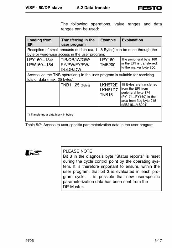
The following operations, value ranges and dataranges can be used:
PLEASE NOTEBit 3 in the diagnosis byte ”Status reports” is resetduring the cycle control point by the operating sys-tem. It is therefore important to ensure, within theuser program, that bit 3 is evaluated in each pro-gram cycle. It is possible that new user-specificparameterization data has been sent from the DP-Master.
Loading from EPI
Transferring in theuser program
Example Explanation
Reception of small amounts of data (ca. 1...8 Bytes) can be done through the byte or word-wise access in the user program:
LPY160...184/LPW160...184
TIB/QB/IW/QW/PY/PW/FY/FW/DL/DR/DW
LPY160TMB200
The peripheral byte 160in the EPI is transferredto the marker byte 200.
Access via the TNB operation*) in the user program is suitable for receivinglots of data (max. 25 bytes):
TNB1...25 (Bytes) LKH572ELKH61D7TNB15
15 Bytes are transferredfrom the EPI fromperipheral byte 174 (PY174...PY160) in thearea from flag byte 215(MB215...MB201).
*) Transfering a data block in bytes
Table 5/7: Access to user-specific parameterization data in the user program
VISF - 50/DP slave 5.2 Data transfer
9706 5-17

VISF - 50/DP slave 5.2 Data transfer
5-18 9706

5.3 CONFIGURATION
PN
368
619
VISF - 50/DP Slave 5.3 Configuration
9706 5-19

Contents
5.3 Specifying the configuration of the SF 50/DP-Slave with COM ET 200 in the DP-Master ......................................................5-21
Operation of COM ET 200, v. 4.x ...................................................5-21Operation of COM ET 200 Windows...............................................5-24Entering properties of the transmitting and receiving data using decimal code configuration bytes ..................................5-27Equipment master data ...................................................................5-29Determining the user-specific parameterization data inthe parameter message of the DP-Master......................................5-30
VISF - 50/DP Slave 5.3 Configuration
5-20 9706
5.3 Specifying the configuration of the SF 50/DP-Slave with COM ET 200 in the DP-Master
This chapter describes the configuration of a SF 50/DP-Slave for a DP-Master. It is assumed, tounderstand this chapter, that the operation of the pa-rameter software "COM ET 200" has been understoodby reading the appropriate manuals of the DP-Masters.
Operation of COM ET 200, v. 4.x• Siemens IM 308-B• FESTO SF 50 (see this chapter)• Other DP-Masters that can be configured using the
COM ET 200, v. 4.x software.
Requirements• Process the "ET 200 - SYSTEM PARAMETERS"
mask• Call up of the "CONFIGURING" mask
1. Enter of station number (Slave address) (areas 3...124 can be used)
2. Select "Area" for addressing e.g.: P,Q for IM 308-B (ET 200 - System parameter "Dual port RAM addressing" = N) P for SF 50
3. Select station type "FESTO SF 50 DP"
The disc accompanying this manual contains the typefiles for the SF 50/DP-Slave using COM ET 200, v. 4.x. The type files can be found in the directoryA:\SIEMENS\SF50\COMET200\GB under the nameFXFB50TE.200.
VISF - 50/DP Slave 5.3 Configuration
9706 5-21

PLEASE NOTEIf "FESTO SF 50 DP" does not appear as the station type in the window, the following reasonsmay apply:Either the relevant type file has not been loadedinto the PT/PC or the model file is held in thewrong directory. The type file for the SF 50/DP-Slave is called FXFB50TE.200 and is stored in theCOM ET 200, v. 4x directory.
4. Select the initial addresses of the transmitting and receiving data e.g.: DI=8, DQ=8, AI=8, AQ=8 for SF 50 as the DP-Master
5. Enter transmitting and receiving data in the "DP identifier" window
- Call up the "DP identifier" mask in the currentfield 0, 1, 2, 3 using [ F7 ] "HELP"
Fig. 5/4: COM ET 200 "Configuring" mask
VISF - 50/DP Slave 5.3 Configuration
5-22 9706

- Enter receiving data from the DP-Master in thefields 0, 1 (transmitting data (outputs) of theSF 50/DP-Slave are the receiving data (inputs)of the DP-Master).
- Enter transmitting data from the DP-Master inthe fields 2, 3 (receiving data (inputs) of the SF 50/DP-Slave are the transmitting data (out-puts) of the DP-Master).
The entry fields must be allocated in increasing se-quence; fields must not be left out.
This ends the address assignment using COM ET 200 v. 4.x.
After completing the address assignment using COM ET 200 for the SF 50/DP-Slave, the same ad-dress identifiers must be entered into the DB1 of the SF 50/DP-Slave. The procedure to follow is describedin chapter 5.4.
PLEASE NOTE
• Only code as many bytes as are required for theactual data transfer. The higher the number ofconfigured bytes, the longer the DP cycle is.
• The SF 50/DP-Slave can prepare a maximum of32 bytes of data for collection by the PROFIBUS-DP and receive a maximum of 32 bytes of datavia the PROFIBUS-DP. Take these limits intoaccount when coding.
• For the SF 50/DP-Slave, the "special identifica-tion format" (Bit 4 + 5 = 00B) cannot be used.
• COM ET 200, v. 4.0, reduces the consistency ofthe "total length" to 8 bytes. Take these limitsinto account when coding.
VISF - 50/DP Slave 5.3 Configuration
9706 5-23
Handling COM ET 200 for Windows(COM Profibus)
The configuration of the SF 50/DP-Slave with the sub-sequent DP-Master is described in the followingmanuals:• Siemens IM 308-C
(Manual on ET 200 Distributed peripheral systems)• Siemens AG S5-95U/DP-Master
(Manual on ET 200 Distributed peripheral system)• FESTO SF 50/DP-Master• Other DP-Masters that can be configured using the
COM ET 200 Windows.
Requirements:• Master system has been designed
- Bus parameters- Host parameters- Master parameters
• MASTERSYSTEM window is called up
1. Select "Valves" button and introduce a new slave
2. Enter the slave station number (station number): _(areas 3...123 can be used)
3. Select "SF 50/DP-Slave" station type
The disc accompanying this manual contains the typefiles for the SF 50/DP-Slave under COM ET 200 forWINDOWS. The type files can be found in the direc-toryA:\SIEMENS\SF50\COMWIN20\SLAVE\GB\FEFB50XE.200
VISF - 50/DP Slave 5.3 Configuration
5-24 9706

PLEASE NOTEIf the "Valves“ button does not appear in the selec-tions for the slaves or the "SF 50/DP-Slave“ stationtype does not appear in the "System parameter“window, the following reasons may apply:- Either the relevant type file has not been loaded into the PG/PC or- The type file is held in the wrong directory.
The type file for the SF 50/DP-Slave is calledFEFB50XE.200 and is stored in the directory \COMWIN20\TYPDAT5X of COM ET 200 forWINDOWS.
4. Enter transmitting and receiving data in the "CON- FIGURING" window.
312
Fig. 5/5: "Configuring" mask in COM ET 200 Windows
4
VISF - 50/DP Slave 5.3 Configuration
9706 5-25

- Call up of the "Configuring" window with the "Con-figure" button in the "Slave parameters" window.
- Enter receiving data from the DP-Master in thefields 0, 1, (default 151, 151 = 2 x 8 byte I).(Transmitting data (outputs) of the SF 50DP/slave are the receiving data (inputs) of theDP-Master.)
- Enter transmitting data from the DP-Master inthe fields 2, 3, (default 167, 167 = 2 x 8 byte O).(Reception data (inputs) of the SF 50/DP-Slaveare the transmitting data (outputs) of the DP-Master.)
The entry fields must be allocated in increasing se-quence; fields must not be left out.• Assign the initial addresses of the transmitting and
receiving data using the input address and outputaddress fields.
e.g.: I-Addr = P008, O-Addr = P008
This ends the address assignment using COM ET 200 for Windows.
After completing the address assignment usingCOM ET 200 Windows for SF 50/DP-Slave, the sameaddress identifiers must be entered into the DB1 ofthe SF 50/DP-Slave. The procecure to follow isdescribed in chapter 5.4.
PLEASE NOTE
• Only code as many bytes as are required for theactual data transfer. The higher the number ofconfigured bytes, the longer the DP cycle is.
• The SF 50/DP-Slave can prepare a maximum of32 bytes of data for collection by the PROFIBUS-DP and receive a maximum of 32 bytes of datavia the PROFIBUS-DP. Take these limits into account when coding.
• For the SF 50/DP-Slave, the "special identifica-tion format" (Bit 4 + 5 = 00B) cannot be used.
VISF - 50/DP Slave 5.3 Configuration
5-26 9706

Entering properties of the transmitting andreceiving data using decimal code configuration bytes
The following describes the coding of the transmittingand receiving data for SF 50/DP-Slave using an ex-ample.
The properties of the transmitting and receiving datamust be entered in bits using the configuration bytes.
Configuration byte7 6 5 4 3 2 1 0
Length of data0000B: 1 byte / word
0001B: 2 bytes / word
0010B: 3 bytes / word
:1111B: 16 bytes / word
Input or output data(defined as out from SF 50/DP-Slave)
00B: Special indentification format (not allowed for SF 50/DP-Slave)
01B: Transmitting data from the SF 50/DP-Slave (inputs in the DP-Master)
10B: Receiving data from the SF 50/DP-Slave (outputs of the DP-Master)
11B: Transmitting and receiving data
Length formats0: Byte structure
1: Word structure
Consistency0: Byte or Word
1: Total length (of COM ET 200, version 4.0 limited to 8 bytes)
Fig. 5/6: Construction of the SF 50/DP-Slave configuration bytes
VISF - 50/DP Slave 5.3 Configuration
9706 5-27

Configuration byte(decimal)
Significance
Input Output0 1 2 3
016 016 032 032 1+1 byte transmitting data, 1+1 byte receiving data,Consistency=0
145 145 161 161 2+2 byte transmitting data, 2+2 byte receiving data,Consistency=1
147 147 163 163 4+4 byte transmitting data, 4+4 byte receiving data,Consistency=1
151 151 167 167 8+8 byte transmitting data, 8+8 byte receiving data,Consistency=1(Default)
159 159 175 175 16+16 byte transmitting data, 16+16 byte receiving data,Consistency=1
Table 5/8: Precise identifiers of the configuration bytes
VISF - 50/DP Slave 5.3 Configuration
5-28 9706

Device database
The disk accompanying this manual contains the de-vice data base (DDB) with the specific, standard de-vice database for the valve terminals.
The device database file can be found in the direc-tory:
A:SIEMENS\SF50\NORM-GSD\VI0XFB50.GSD
The equipment master data contains all the typicalslave entries (ident-number, revision, etc. ...) and thelimits for the identifiers:- max. 4 identifier bytes can be used- max. 32-byte inputs- max. 32-byte outputs
PLEASE NOTEIn total max. 4 identifiers can be configured. Pleasetake into account the max. number of 32 bytes.
Example:Valve terminal with 16-byte transmitting data and 16-byte receiving data:Identifier byte 0: 151 = 8-byte DI/consistency = 1 (> 8 Byte)
Identifier byte 1: 151 = 8-byte DI/consistency = 1 (> 8 Byte)
Identifier byte 2: 167 = 8-byte DO/consistency = 1 (> 8 Byte)
Identifier byte 3: 167 = 8-byte DO/consistency = 1 (> 8 Byte)
VISF - 50/DP Slave 5.3 Configuration
9706 5-29

Determining the user-specific parameterizationdata in the parameter message of the DP-Master
Case A, COM ET 200 v. 4.x
The "CONFIGURING" mask (figure 5/4) is open andthe station type FESTO SF 50 DP has been selected.
- Press [ Shift ] and [ F6 ] "DP slave parameterization frame".
Case B, COM ET 200 Windows
The "Slave parameters" mask (station type FESTOSF 50 DP) is open. Select the button [Parameterize]
The "DP slave PARAMETERIZATION FRAME" win-dow appears in the mask as follows:
The 25 bytes in the parameterization frame can beused as required.
The following shows an example of determining user-specific parameterization data.
DP-SLAVE - PARAMETRIZATION FRAMEByte (Entry in KH format)
0 00 00 00 00 00 00 00 00 00 0010 00 00 00 00 00 00 00 00 00 0020 00 00 00 00 00
Fig. 5/7: DP parameterization frame 1
VISF - 50/DP Slave 5.3 Configuration
5-30 9706

Example:
The analogue value on the analogue output of the SF 50/DP-Slave must be incremented from 0 V insteps of 20 up to the limiting value 8 V (equals 8000).When the limiting value has been reached, values be-gin again at 0 V.
1. Enter the value for the step 20 D = 0014 H (Byte 1 + 2) and the limiting value 8000 D = 1F40 H (Byte 3 + 4) in the window "DP slave PARAMETERIZATION FRAME".
The window "DP slave PARAMETERIZATIONFRAME" will now appear as follows:
2. Finish the entries.
Access to the user-specific parameterization data inthe user program of the SF 50/DP-Slave is describedin chapter 5.2.
DP slave - PARAMETERIZATION FRAMEByte (Entry in KH format)
0 00 14 1F 40 00 00 00 00 00 0010 00 00 00 00 00 00 00 00 00 0020 00 00 00 00 00
Fig. 5/8: DP parameterization frame 2 (example)
VISF - 50/DP Slave 5.3 Configuration
9706 5-31

VISF - 50/DP Slave 5.3 Configuration
5-32 9706

5.4 PARAMETERIZATION DB1
PN
368
619
VISF - 50/DP Slave 5.4 Parameterization DB1
9706 5-33
Contents
5.4 Parameterising the PROFIBUS-DP interface of the SF 50/DP-Slave in DB1 .................................................................5-35
Parameterization process. ...............................................................5-36DB1 parameters for the SF 50/DP-Slave with PROFIBUS-DPinterface..................... ......................................................................5-37Enter parameters in the DB1 and in the SF 50/DP-Slave ..............5-39DB1 Parameterization faults for PROFIBUS-DP interface..............5-41
VISF - 50/DP Slave 5.4 Parameterization DB1
5-34 9706

5.4 Parameterising the PROFIBUS-DP interface of the SF 50/DP-Slave in DB1
The following is parameterised in the DB1 parameterblock with the block description "DPS":
• The slave address of the SF 50/DP-Slave as aPROFIBUS-DP bus slave (hereafter called the station number).
• The configuration data for transmitting and receiv-ing over the PROFIBUS-DP interface.
The DB1 contains a default setting for thePROFIBUS-DP interface. Figure 5.9 shows the pre-set (default) DB1.
0: KC = ’ D B 1 # S L 1 : S L N 1 S F D B 2 ’12: KC = ’ D W0 E F D B 3 D W0 K B ’24: KC = ’ E M B 1 0 0 K B S M B 1 0 1 ’36: KC = ’ P G N 1 ; # S D P : N T 1 2 ’48: KC = ’ 8 ; T F B : O B 1 3 1 0 0 ; # ’60: KC = ’ D P S : T L N 3 D P A E 1 5 1 ’72: KC = ’ 1 5 1 1 6 7 1 6 7 ; # E N D ’
Fig. 5/9: DB1 with default parameters
VISF - 50/DP Slave 5.4 Parameterization DB1
9706 5-35

Parameterization process
The DP-Master sends the parameterization and con-figuration data to each DP-Slave. As the DP-Slave,the SF 50 compares the data received with the locallyconfigured data in the DB1, and transmits the result inthe diagnosis information back to the DP-Master. Ifthe data is in agreement then the data exchange viathe PROFIBUS-DP is immediately possible.
parameterization and configuration message
DP-Master
Results message in the diagnosisinformation for the DP-Master
Data exchange is possible
SF 50/DP-Slave
Comparison between message from the DP-Master and the parameter block"DPS:" in DB1.
parameterization andconfiguration data forthe DP-Slave, as produced using COM ET 200.The DP-Slave is correctly paramete-rised and configured.
Fig. 5/10: Diagram: parameterization procedure of the DP-Slave
VISF - 50/DP Slave 5.4 Parameterization DB1
5-36 9706

DB1 parameters for the SF 50/DP-Slave with PROFIBUS-DP interface
Example:
An SF 50 will be parameterised as the DP-Slave onthe PROFIBUS-DP.
Requirements for parameterization in DB1
Using COM ET 200, the following data have been en-tered in the DP-Master (chapter 5.3): • The station number of the SF 50/DP-Slave and • The address identification (configuration data) for
the SF 50/DP-Slave.
The same data is entered in the DB1 as in COM ET 200, i.e. the station number and configura-tion data that was coded in chapter 5.3 and entered inthe COM ET 200 must be entered in the followingsample DB1 .
Parameter Argument SignificanceBlock identifier: DPS: PROFIBUS-DP interface
TLN 3...124 Station number of the SF 50/DP-Slave
DPAE 16... 3;80...127;144...191;208...256
Determine the following decimal codeconfiguration data:• Are they transmitting or receiving data?• Length of the data• Length format of the data• Consistency of the data(Procedure for coding the data, see chapter 5.3. )
Table 5/9: PROFIBUS-DP, DB1 parameters
VISF - 50/DP Slave 5.4 Parameterization DB1
9706 5-37

PLEASE NOTEThe exceptions to the transfer of data produced inCOM ET 200 are the configuration bytes that areautomatically modified by COM ET 200, e.g.: 1 Byte inputs = 016 ⇒ 8DI.1 Byte outputs = 032 ⇒ 8DOThese configuration bytes must be entered into theDB1 (chap. 5.3) in decimal code.
The following assignments are used as an example inchapter 5.3 in COM ET 200:• Station number: 3• Station type: SF 50 DP (not entered in DB1)• Address identification: 151; 151; 167; 167
(The address identifications must entered in pre-cisely this order into the DB1.)
This produces the structure of the parameter block"DPS:" in the sample DB1 as follows:
The sample DB1 shown in table 5/10 is used for adetailed sample program in chapter 5.5.
DB1 parameters for PROFIBUS-DP Explanation:48: KC =’8 ; TFB: OB13 100 ; #’;60: KC =’ DPS: TLN 3 DPAE 151 ’;72: KC =’151 167 167 ;# END ’;
Station no. of the SF 50/DP-Slave is 3decimal code configuration data, significance see chapter 5.3.
Table 5/10: Sample DB1 for PROFIBUS-DP (default)
VISF - 50/DP Slave 5.4 Parameterization DB1
5-38 9706
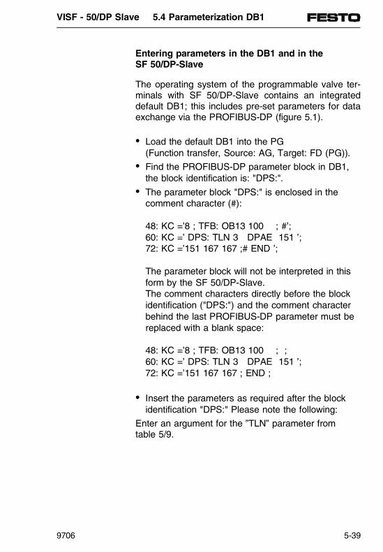
Entering parameters in the DB1 and in the SF 50/DP-Slave
The operating system of the programmable valve ter-minals with SF 50/DP-Slave contains an integrateddefault DB1; this includes pre-set parameters for dataexchange via the PROFIBUS-DP (figure 5.1).
• Load the default DB1 into the PG (Function transfer, Source: AG, Target: FD (PG)).
• Find the PROFIBUS-DP parameter block in DB1,the block identification is: "DPS:".
• The parameter block "DPS:" is enclosed in thecomment character (#):
48: KC =’8 ; TFB: OB13 100 ; #’;60: KC =’ DPS: TLN 3 DPAE 151 ’;72: KC =’151 167 167 ;# END ’;
The parameter block will not be interpreted in thisform by the SF 50/DP-Slave.The comment characters directly before the blockidentification ("DPS:") and the comment characterbehind the last PROFIBUS-DP parameter must bereplaced with a blank space:
48: KC =’8 ; TFB: OB13 100 ; ;60: KC =’ DPS: TLN 3 DPAE 151 ’;72: KC =’151 167 167 ; END ;
• Insert the parameters as required after the blockidentification "DPS:" Please note the following:
Enter an argument for the ”TLN” parameter fromtable 5/9.
VISF - 50/DP Slave 5.4 Parameterization DB1
9706 5-39

- Maintain the precise sequence of parameters inthe parameter block; "TLN" before "DPAE". In ad-dition, the address identification must be enteredafter "DPAE" in the same sequence, as forCOM ET 200.
WARNINGOnly overwrite the default parameter, do not intro-duce other characters.
- Follow the same rules for the parameterization ofthe DB1.
• Transfer the modified DB1 into the SF 50/DP-Slave.This overwrites the default DB1.
• Save the program in the EEPROM module (see chap. 3.3).
• Initiate a STOP ⇒ RUN transition, the SF 50/DP-Slave will then accept the modified parameters.
VISF - 50/DP Slave 5.4 Parameterization DB1
5-40 9706

DB1 parameterization faults for PROFIBUS-DP interface
The DB1 parameterization faults can be read as faultcodes. Firstly, it must be determined in the DB1 pa-rameter block "ERT" where the fault codes should bestored (in the flag area or in a data block).
The left byte contains the fault code, which is listed inthe following table. The right byte always contains thefault location "15H“ for the DPS: PROFIBUS-DP pa-rameter block entered. Chapter 3.8. clearly describesthe entry of the ERT parameters.
Fault code of the DB1 Interpreter
(left byte in DW or MW)
Significance
17H PROFIBUS-DP interface is not operational30H Parameter block "DPS:" is already present60H DB1 Parameter "TLN" or the argument behind
"TLN" is missing61H DB1 Parameter "DPAE" or arguments behind
"DPAE" are missing63H Length of the transmitting and/or receiving data
according to "DPAE" is too big (> 32 bytes)64H Number of arguments according to "DPAE" is
too big (> 32 bytes)65H Use special identifier format
(not allowed for the SF 50/DP-Slave)
Table 5/11: Fault code of the DB1 interpreter
VISF - 50/DP Slave 5.4 Parameterization DB1
9706 5-41

VISF - 50/DP Slave 5.4 Parameterization DB1
5-42 9706

5.5 SAMPLE PROGRAM
PN
368
619
VISF - 50/DP Slave 5.5 Sample program
9706 5-43

Contents
5.5 Sample program for the SF 50 as a PROFIBUS-DP-Slave........5-45Cyclic program for the SF 50 as a DP-Slave..................................5-46
VISF - 50/DP Slave 5.5 Sample program
5-44 9706

5.5 Sample program for the SF 50 as a PROFIBUS-DP-Slave
This chapter looks more closely at the structure of theuser program for an SF 50 used as a PROFIBUS-DP-Slave. The data are cyclically exchanged withouttransmission or reception request. The DP-Master in-itiates this process. The data exchange is made viathe PROFIBUS-DP, independently from the cycle con-trol point of the SF 50/DP-Slave.
Example:
An SF 50 is the DP-Slave on the PROFIBUS-DP. It issupplied with data by a DP-Master and transmits datato the master.
The program structure of the following sample pro-gram is limited to the data exchange between the SF 50/DP-Slave and the DP-Master.
OB 1
Call up of FB 212and other modules.
FB 212
Data exchange between the SF 50/DP-Slaveand a DP-Master.
Fig. 5/11: Program structure
VISF - 50/DP Slave 5.5 Sample program
9706 5-45

Cyclic program for the SF 50 as a DP-Slave
Proceed as follows: • Configure and parametrise the SF 50 as a
PROFIBUS-DP-Slave as described in chapters 4and 5.
• Transfer the OB1 and FB212 modules into the SF 50/DP-Slave.
OB1 Explanation:JU FB 212 Call up of the FB212 data exchangeName :DP-TEST:
Fig. 5/12: OB1 program
FB212 ExplanationName :DP-TEST:L PY 254 Diagnosis status messages (see chap. 8.1):T FY 104 Saving diagnosis status messages:AN F 104.5 Test bit 5 of the status messages: if this bit = 0, there is no : commissioning by the DP-Master:BEC ==> Abort by BEC:: SF 50/DP-Slave TRANSMITTING TO DP-Master: Send BIT INFORMATION:L KH 0000 The value 0000hex is:T FY 20 saved in FY 20::AN F 20.0 If bit 0 = 0, then:S F 20.0 set bit 0 in FY 20:AN F 20.4 If bit 4 = 0, then:S F 20.4 set bit 4 in FY 20:L FY 20 Load MB 20 and:T PY 128 transfer to PY 128
Fig. 5/13: OB212 program
VISF - 50/DP Slave 5.5 Sample program
5-46 9706

FB212 ExplanationSend BYTE INFORMATION
:L FY 21 Load FY 21 and:T PY 129 transfer to PY 129:: Send WORD INFORMATION:L FW 22 Load FW 22 and:T PW 130 transfer to PW 130 (addr. 5782h...5783h):: Send MULTIPLE DATA: If the data must be prepared ⇒ Variant 2: If the data are already saved ⇒ Variant 1:: VARIANT 1: Data are already saved:L KH 0102 Preparation: The value 0102hex is:T FW 64 saved in FW 64 (FY 64, FY 65): Address: FY 64 = 6140h; FY 65 = 6141h: Address allocation of the RAM memory (see chap. 3.5)::L KH 0304 The value 0304hex is:T FW 66 saved in FW 66 (FY 66, FY 67)
Address: FY 66 = 6142h; FY 67 = 6143hData are now stored
:L KH 6143 Source: Address of FY 67:L KH 5787 Target: Address of PY 135 = 5787hex:TNB 4 4 bytes from the source (FY 67, 66, 65, 64): are transferred to the target (PY 135, 134, 133, 132): FY 67 ⇒ PY 135; FY 66 ⇒ PY 134 etc.:: VARIANT 2: Data preparation e.g.: L KHxxx:L KH 5566 The value 5566hex is:T PW 136 transferred to PW 136:L KH 7788 The value 7788hex is:T PW 138 transferred to PW 138:::
Fig. 5/14: FB212 program (continuation)
VISF - 50/DP Slave 5.5 Sample program
9706 5-47
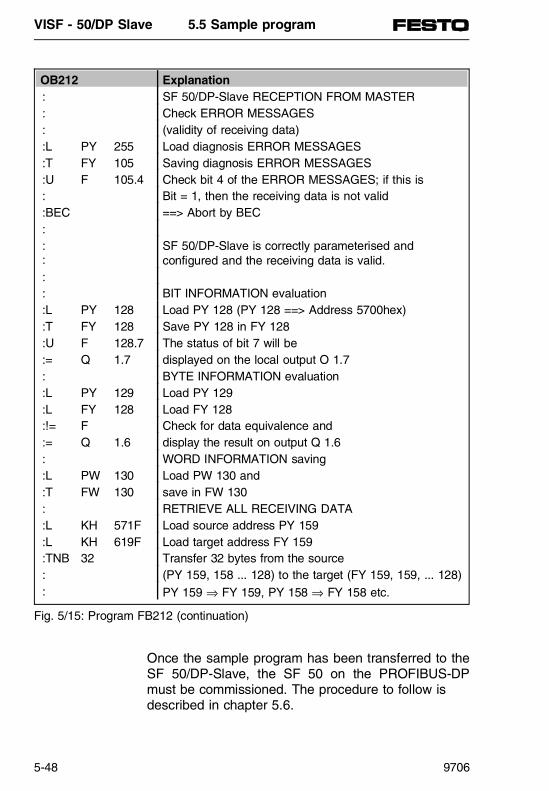
Once the sample program has been transferred to theSF 50/DP-Slave, the SF 50 on the PROFIBUS-DPmust be commissioned. The procedure to follow isdescribed in chapter 5.6.
OB212 Explanation: SF 50/DP-Slave RECEPTION FROM MASTER: Check ERROR MESSAGES: (validity of receiving data):L PY 255 Load diagnosis ERROR MESSAGES:T FY 105 Saving diagnosis ERROR MESSAGES:U F 105.4 Check bit 4 of the ERROR MESSAGES; if this is: Bit = 1, then the receiving data is not valid:BEC ==> Abort by BEC:::
SF 50/DP-Slave is correctly parameterised and configured and the receiving data is valid.
:: BIT INFORMATION evaluation:L PY 128 Load PY 128 (PY 128 ==> Address 5700hex):T FY 128 Save PY 128 in FY 128:U F 128.7 The status of bit 7 will be:= Q 1.7 displayed on the local output O 1.7: BYTE INFORMATION evaluation:L PY 129 Load PY 129:L FY 128 Load FY 128:!= F Check for data equivalence and:= Q 1.6 display the result on output Q 1.6: WORD INFORMATION saving:L PW 130 Load PW 130 and :T FW 130 save in FW 130: RETRIEVE ALL RECEIVING DATA:L KH 571F Load source address PY 159:L KH 619F Load target address FY 159:TNB 32 Transfer 32 bytes from the source: (PY 159, 158 ... 128) to the target (FY 159, 159, ... 128): PY 159 ⇒ FY 159, PY 158 ⇒ FY 158 etc.
Fig. 5/15: Program FB212 (continuation)
VISF - 50/DP Slave 5.5 Sample program
5-48 9706

5.6 COMMISSIONING
PN
368
619
VISF - 50/DP Slave 5.6 Commissioning
9706 5-49

Contents
5.6 Commissioning of the SF 50/DP-Slave .......................................5-51Start-up behaviour of the SF 50/DP-Slave......................................5-51Start-up of PROFIBUS-DP ..............................................................5-52Start-up of the SF 50/DP-Slave with STOP-RUN transition ...........5-52STOP RUN transition of the SF 50/DP-Slave without DB1-changes in the parameter block "DPS:"..........................................5-52STOP RUN transition of the SF 50/DP-Slave with DB1-changes in the parameter block "DPS:"..........................................5-52STOP status of the SF 50/DP-Slave...............................................5-53Instructions for the configuration and installation of the SF 50/DP-Slave.............. ...........................................................5-54Requirements for commissioning the SF 50/DP-Slave as a PROFIBUS-DP slave ...................................5-56Starting sequence of the SF 50/DP-Slave as PROFIBUS-DP slave.......................................................................5-58Working steps for commissioning the SF 50/DP-Slave as a PROFIBUS-DP slave ...................................5-58
VISF - 50/DP Slave 5.6 Commissioning
5-50 9706

5.6 Commissioning of the SF 50/DP-Slave
This chapter contains information concerning: • The behaviour during start-up of the SF 50/DP-
Slave with the PROFIBUS-DP interface and • how to operate the SF 50/DP-Slave on the
PROFIBUS-DP.
Start-up behaviour of the SF 50/DP-slave
The following diagram shows the start-up of the SF 50/DP-Slave.
1) If the SF 50 DP/slave, during SYSTEM OFF, was in RUN
Read out PIO
Processing OB1
Read in PII
Release of outputs
Processing OB21
Interpretation of the DB1start-up of the L2-DP interface
Processing OB22
Mains power restoration 1)PC STOP - RUN command
Resets the Process Image (PI), thenon-remanent times, counters, flags,
the extended peripheral areas
Newstart
routineSTOPLED
lights up
Start upSTOP
andRUN LEDlights up
RUNRUN LEDlights up
Resets the Process Image (PI), thenon-remanent times, counters, flags,
the extended peripheral areas
Interpretation of the DB1start-up of the L2-DP interface
Fig. 5/16: Start-up behaviour of the SF 50/DP-Slave during SYSTEM ON or STOP⇒RUN transition
VISF - 50/DP Slave 5.6 Commissioning
9706 5-51

It is assumed, from this point, that the parameterblock "DPS:" is in the DB1 and is correct. ThePROFIBUS-DP interface is then activated at the endof the new start routine (figure 5/16).
Starting up PROFIBUS-DP
During start up of the PROFIBUS-DP, in addition tothe DP slave-specific data (configuration and parame-terization data), user-specific parameterization datacan be transmitted to the DP slaves (chap. 5.2).
Starting up the SF 50/DP-Slave with STOP-RUNtransition
During start-up of the SF 50/DP-Slave, the extendedperipheral area - outputs (EPO) can be initialised.This initialisation can be implemented by program-ming in the OB 21 start-up. Without specific initialisa-tions the EPO are initialised with "0".
PLEASE NOTEIt has not been ascertained that the pre-assigneddata can be collected by the DP master, as thePLC cycle and the DP cycle operate asynchro-nously (see chap. 5.2).
STOP - RUN transition of the SF 50/DP-Slave with-out DB1 changes in the "DPS" parameter block
Data exchange over the PROFIBUS-DP is possiblewithout new parameterization and configuration mes-sages from the DP-Master.
STOP RUN transition of the SF 50/DP-Slave withDB1 changes in the parameter block "DPS:"
If, in the "DPS" parameter block the parameter"DPAE" has been changed, then a new appropriateparameterization and configuration message must besent from the DP-Master to the SF 50/DP-Slave.
VISF - 50/DP Slave 5.6 Commissioning
5-52 9706

If the configuration data in the COM ET 200 of theDP-Master match up with the data in the DB1 of the SF 50/DP-Slave, then a data exchange with the DP-Master is possible (chap. 5.4 "Parameterization proce-dure").
If the station number in the DB1 is changed, the DP-Master cannot communicate with the SF 50/DP-slave.The station number must therefore be changed inCOM ET 200.
Changing other parameter blocks in the DB1 does notinfluence the data exchange via the PROFIBUS-DP.
STOP status of the SF 50/DP-Slave
The DP-Master can only request all diagnosis infor-mation for PROFIBUS-DP from the SF 50/DP-Slave.
VISF - 50/DP Slave 5.6 Commissioning
9706 5-53

Instructions for the configuration and installationof the SF 50/DP-Slave
The following section contains general instructions forthe configuration and commissioning of a unit withprogrammable logical controllers.
As the product is generally used as a componentwithin larger systems or units, these instructionsshould be used as a guideline for the safe integrationof the product into its environment.
WARNING• The safety and accident prevention regulations
valid for all specific cases must be complied with.• For equipment with fixed connections (built-in
equipment/systems), without an all-pole mains dis-connector and/or fuses, a mains disconnector orfuse must be installed within the site installation;the unit should be connected to a protective earth.
• For equipment that is run on the mains supply, it isnecessary to check before commissioning whetherthe set nominal voltage range corresponds to thelocal mains voltage.
• With 24 V power supply, it is important to ensure asafe electrical isolation of the extra-low-voltage.Only use power supply units complying with IEC364-4-41 or HD 384.04.41 (VDE 0100 part 410).
• Fluctuations or deviations of the mains voltagefrom the nominal value must not exceed the toler-ance limits given in the technical data, otherwisefunctional failures and hazardous conditions mayaffect the electrical units/equipment.
• Preventative measures must be taken to ensurethat a program interrupted by voltage drops andfailures can be retrieved. This must also ensurethat temporary hazardous operating conditions donot occur. Where required the "EMERGENCY STOP" shouldbe used.
VISF - 50/DP Slave 5.6 Commissioning
5-54 9706

• All EMERGENCY STOP equipment, in compliancewith EN 60204/IEC 204 (VDE 0113), must remaineffective in all operating modes of the automationequipment. Releasing the EMERGENCY STOPequipment should not lead to any uncontrolled orundefined start-up.
• Connection and signal wiring must be installed insuch a manner that any inductive or capacitive in-terference does not affect the automation functions.
• Automation equipment and the relative operatingelements must be installed in such a manner thatthey are sufficiently protected against unintentionalcontact.
• In order that a cable or core break on the signalside does not lead to undefined conditions in theautomation equipment, the appropriate safety pre-cautions must be taken at the hardware and soft-ware level for the I/O couplings.
VISF - 50/DP Slave 5.6 Commissioning
9706 5-55
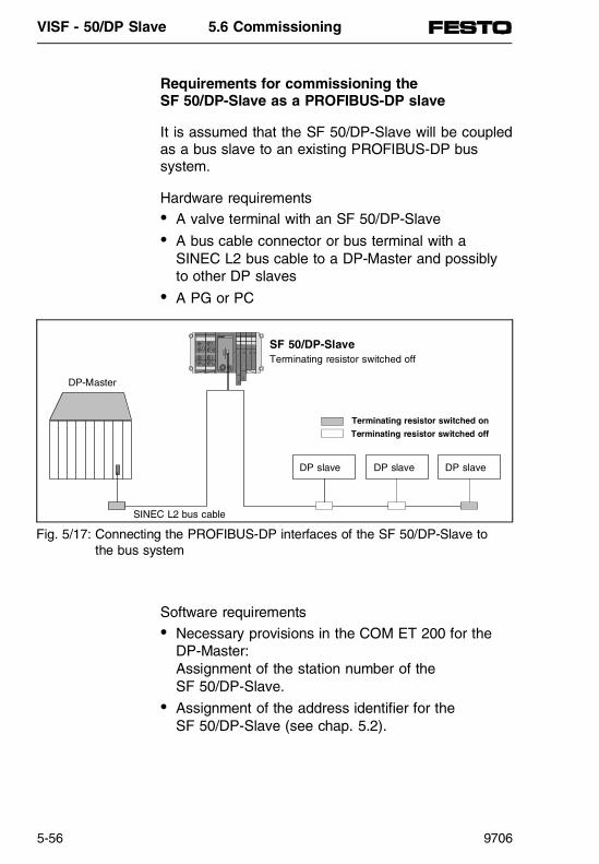
Requirements for commissioning the SF 50/DP-Slave as a PROFIBUS-DP slave
It is assumed that the SF 50/DP-Slave will be coupledas a bus slave to an existing PROFIBUS-DP bus system.
Hardware requirements• A valve terminal with an SF 50/DP-Slave • A bus cable connector or bus terminal with a
SINEC L2 bus cable to a DP-Master and possiblyto other DP slaves
• A PG or PC
Software requirements• Necessary provisions in the COM ET 200 for the
DP-Master:Assignment of the station number of the SF 50/DP-Slave.
• Assignment of the address identifier for the SF 50/DP-Slave (see chap. 5.2).
DP slave DP slave DP slave
SF 50/DP-SlaveTerminating resistor switched off
DP-Master
SINEC L2 bus cable
Terminating resistor switched on
Terminating resistor switched off
Fig. 5/17: Connecting the PROFIBUS-DP interfaces of the SF 50/DP-Slave tothe bus system
VISF - 50/DP Slave 5.6 Commissioning
5-56 9706

Necessary parameterization in the DB1 of the SF 50/DP-Slave: • Parameterization of the station number of the
SF 50/DP-Slave.• Parameterization of the address identifier for the
SF 50/DP-Slave (see chap. 5.4).
VISF - 50/DP Slave 5.6 Commissioning
9706 5-57

Starting sequence of the SF 50/DP-Slave as PROFIBUS-DP slave
The following sequence must be maintained duringthe connection of valve terminals with SF 50/DP-Slaves to the PROFIBUS-DP:• Turn on the power supply of all the
SF 50/DP-Slaves. • Switch all SF 50/DP-Slaves from STOP to RUN.
The DP-Master or the programmable controller withthe DP-Master must be switched on after the DPslaves. The commissioning of the entire PROFIBUS-DP is described below.
Working steps for commissioning the SF 50/DP-Slave as a PROFIBUS-DP slave
Follow the steps below for commissioning a valve ter-minal with SF 50 as a DP slave:• Start up the valve terminal without the PROFIBUS-
DP interface (as described in chap. 3.3).• Start up the PROFIBUS-DP interface following the
procedure diagram below.
VISF - 50/DP Slave 5.6 Commissioning
5-58 9706

Mains on andoperating mode set to
STOP
DP slave parameterisedin DB1
STOP RUN(SF 50 new start) BF LED lights up
SF 50/DP-Slave goes into RUN?
Bit 1=1
DB1 is faulty Switch SF 50/DP-Slave to STOP and
In the diagnosis byte "Error messages"
Bit 5=1
Switch SF 50/DP-Slave to STOP and modify or activate the DB1 ”DPS”parameter block (delete the comment characters).
Modify the parameterization or configuration in the DP- Master or switch the SF 50/ DP-Slave to STOP and change the configuration in the DB1 (chap. 5.4).
In the diagnosis byte"Error messages"
In the diagnosis byte"Status messages"
The SF 50/DP-Slave wascorrectly parametrised and con-figured by the DP-Master, theBF LED turns off, the SF 50/ DP slave is ready for the dataexchange with the DP-Master.
No
Yes
Yes
No
Yes
Yes
No
No
Fig. 5/18: Operating procedure for commissioning the SF
VISF - 50/DP Slave 5.6 Commissioning
9706 5-59

Once the SF 50/DP-Slave is in the operating modeRUN (figure 7.3), it is recommended that the programbe saved in the EEPROM of the SF 50(see chap. 3.3).
VISF - 50/DP Slave 5.6 Commissioning
5-60 9706

5.7 TESTING AND DIAGNOSIS
PN
368
619
VISF - 50/DP Slave 5.7 Testing and diagnosis
9706 5-61
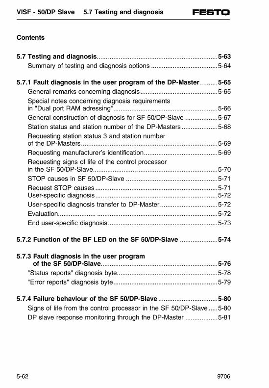
Contents
5.7 Testing and diagnosis...................................................................5-63Summary of testing and diagnosis options .....................................5-64
5.7.1 Fault diagnosis in the user program of the DP-Master..........5-65General remarks concerning diagnosis...........................................5-65Special notes concerning diagnosis requirements in "Dual port RAM adressing"..........................................................5-66General construction of diagnosis for SF 50/DP-Slave ..................5-67Station status and station number of the DP-Masters ....................5-68Requesting station status 3 and station number of the DP-Masters............................................................................5-69Requesting manufacturer’s identification.........................................5-69Requesting signs of life of the control processor in the SF 50/DP-Slave.....................................................................5-70STOP causes in SF 50/DP-Slave ...................................................5-71Request STOP causes ....................................................................5-71User-specific diagnosis....................................................................5-72User-specific diagnosis transfer to DP-Master................................5-72Evaluation..................... ...................................................................5-72End user-specific diagnosis.............................................................5-73
5.7.2 Function of the BF LED on the SF 50/DP-Slave .....................5-74
5.7.3 Fault diagnosis in the user program of the SF 50/DP-Slave.................................................................5-76
"Status reports" diagnosis byte........................................................5-78"Error reports" diagnosis byte..........................................................5-79
5.7.4 Failure behaviour of the SF 50/DP-Slave .................................5-80Signs of life from the control processor in the SF 50/DP-Slave .....5-80DP slave response monitoring through the DP-Master ..................5-81
VISF - 50/DP Slave 5.7 Testing and diagnosis
5-62 9706

5.7 Testing and diagnosis
This chapter contains information concerning:
• which testing and diagnosis options are available, • how to diagnose the PROFIBUS-DP interface of
the SF 50/DP-Slave in the user program of the DP-Master,
• what the BF LED on the SF 50/DP-Slave displays, • how to diagnose the PROFIBUS-DP interface of
the SF 50/DP-Slave in the user program of the SF 50/DP-Slave, and
• how the SF 50/DP-Slave behaves during a failureof the PROFIBUS-DP interface.
VISF - 50/DP Slave 5.7 Testing and diagnosis
9706 5-63

Summary of testing and diagnosis options
The following table contains all the testing and diag-nosis options which are available to the SF 50/DP-Slave.
Testing/Diagnosispossibilities
Explanation Description in Chapter
Testing with COM ET 200 v. 4.x
In the COM ET 200 ”STATUS/CONTROL” maskthe current input or output data (seen from theDP-Master side) are displayed. It is possible tocontrol the output data (transmitting data to theSF 50/DP-Slave).
4.3
Fault diagnosis withCOM ET 200 v.4.x
It is possible to display, per station, up to fourdiagnosis messages in plain text.
Fault diagnosis inthe user programof the DP-Master
The following diagnosis information from the SF 50/DP-Slave is available to the DP-Master: - Station status (3 bytes)- Station number of the DP-Masters (1 byte)- Manufacturer’s identification (2 bytes)- Signs of life of the control processor in the Master (1 byte)- STOP cause in the Master (2 bytes)- User-specific diagnosis (6 bytes)
5.7
Function of the BF LED on the SF 50/DP-Slave
The BF LED (Bus Fault LED) is a general faultdisplay.
5.1
Fault diagnosis inthe user programof the SF 50/DP-Slave
The following diagnosis information is availableto the SF 50 as a DP slave: - "Status messages" diagnosis byte- "error reports" diagnosis byte
5.7
Table 5/12: Summary of testing and diagnosis options for the SF 50/DP-Slave
VISF - 50/DP Slave 5.7 Testing and diagnosis
5-64 9706

5.7.1 Fault diagnosis in the user program of the DP-Master
General remarks concerning diagnosis
A fault can be systematically localised and evaluatedin the user program of the DP-Master:
The "summary" and "parameterization and ad-dressability" diagnoses are applicable for all slave sta-tions. They are therefore described in the appropriateDP-Master manual (e.g.: for the FESTO SF 50/DP-Master in chapter 4.3).
The diagnosis "Station status" and "device related diagnosis" are special diagnosis tools for the SF 50/DP-Slave. They are therefore described in thefollowing chapters.
To avoid confusion, the following chapters refer tothe: • two diagnosis bytes of the diagnosis word as
"diagnosis address" and "diagnosis address +1".
Diagnosis ExplanationDiagnosis ”summary” Comprises all stations where diagnosis data is
available Diagnosis of "Parameteri-zation and addressability"
Comprises all stations, that are parameterisedand addressable
Station status Gives information concerning the status of theslave station
Table 5/13: Diagnosis options in the user program
VISF - 50/DP Slave 5.7 Testing and diagnosis
9706 5-65

Special notes concerning diagnosis requirementsin ”Dual port RAM addressing”
During dual port RAM addressing, the diagnosis wordis held on the "master page frame". The master pageframe must be "toggled on" before any diagnosis canoccur.
Precise information concerning the dual port RAM ad-dressing for the DP-Master from Siemens can befound in the equipment manual "ET 200 DistributedI/O System".
VISF - 50/DP Slave 5.7 Testing and diagnosis
5-66 9706

General structure of diagnosis for SF 50/DP-Slave
The station status and the device-related diagnosisare described below, as they are typical of the SF 50as the DP slave.
16 bytes are reserved per slave station for the stationstatus (station status 1...3, station number of the DP-Master and manufacturer’s identification) and device-related diagnosis. These 16 bytes are grouped into 8words. These words are structured as follows:
Word n+1+x1)
Code x2)Diagnosis address Diagnosis address + 1
0 Station status 1 Station status 21 Station status 3 Station number of the
DP-Masters2 Manufacturer’s identification3 Device-related diagnosis:
HeaderDevice-related diagnosis:Signs of life of the controlprocessor in the SF 50/DP-Slave
4 Device-related diagnosis:STOP cause in the SF 50/DP-Slave
Device-related diagnosis:STOP cause in the SF 50/DP-Slave
5 Device-related diagnosis:User-specific diagnosis
Device-related diagnosis:User-specific diagnosis
6 Device-related diagnosis:User-specific diagnosis
Device-related diagnosis:User-specific diagnosis
Table 5/14: Construction of the station status and device-related diagnosis
1) Diagnosis with the integrated function module FB 230 of the SF 50 as master (see chapter 4.3)2) Diagnosis for SIEMENS IM 308-C
VISF - 50/DP Slave 5.7 Testing and diagnosis
9706 5-67

Station status and station number of the DP-Master
The "Station status 1...3" bytes provide information onthe slave station.
Diagnosis word "Station status 1 and 2", Code 0, Word n + 1Diagnosis address "Station status 1"
Diagnosis address + 1"Station status 2"
7 6 5 4 3 2 1 0 7 6 5 4 3 2 1 0
1: slave station must be parameterised again
1: PLC is in the operating mode STOP (STOP cause in this chapter)
Bit is always ”1”
1: Response monitoring is activated
Not assigned
Not assigned
Bit is always ”0”
0: DP-Master is connected to the slave station1: DP-Master is not connected to the slave station
1: slave station is not addressable
1: slave station is not ready for data exchange
1: The configuration data sent from the DP-Master to the slave station do not agree with the structure of the slave station
1: Device-related diagnosis is available
1: The function requested by the DP-Master is not supported by the slave station
Bit is always ”0”
1: The parameterization data sent by the DP-Master is not recognised by the SF 50/DP-Slave (parameterization error)
1: slave station has been parameterised by another DP-Master
Table 5/15: Structure of a diagnosis word based on a request for station status (station status 1)
VISF - 50/DP Slave 5.7 Testing and diagnosis
5-68 9706

Requesting station status 3 and the station num-ber of the DP master
The "Station number of the DP-Master" bit containsthe station number of the master station which hasparameterised the slave station.
Requesting manufacturer’s identification
The "Manufacturer’s identification" byte contains thetype of slave station.
"Station status 3" diagnosis word and station number of the Mastercode 1, Word n + 2
Diagnosis address "Station status 3"
Diagnosis address + 1"Station status of the
DP-Master"7 6 5 4 3 2 1 0 7 6 5 4 3 2 1 0
Irrelevant Station number of the DP-Master which parameterised theslave station (FFH =slave station has not been parameterisedby any DP-Master).
Table 5/16: Structure of the diagnosis word based on a request for station status (Station status 3 and station number of the DP-Master) Diagnosis address "Station status 3"
"Manufacturer’s identification" diagnosis word code 2, Word n + 3
Manufacturer’s identification
15 14 13 12 11 10 9 8 7 6 5 4 3 2 1 0
1 1 1 1 1 1 0 0 0 1 0 1 0 0 0 0
Manufacturer identification for the SB 50/DP-Slave(=FB50H)
Table 5/17: Structure of the diagnosis word based on a request for the manufacturer’s identification
VISF - 50/DP Slave 5.7 Testing and diagnosis
9706 5-69
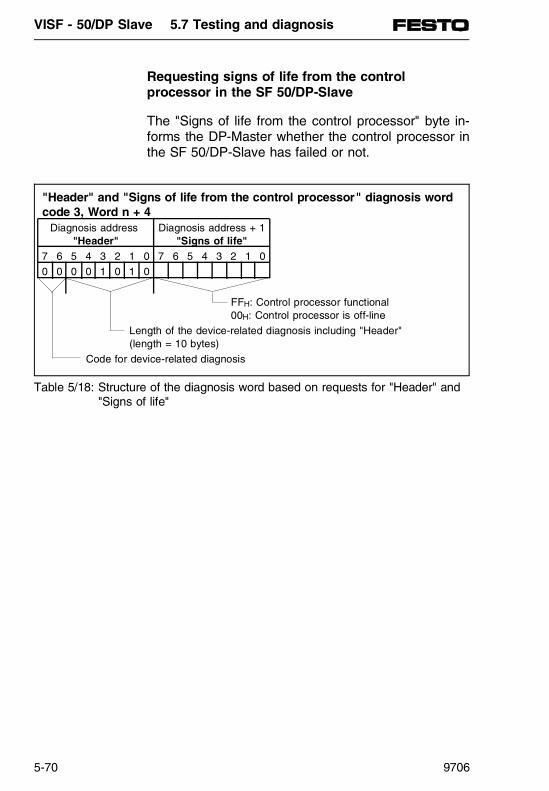
Requesting signs of life from the controlprocessor in the SF 50/DP-Slave
The "Signs of life from the control processor" byte in-forms the DP-Master whether the control processor inthe SF 50/DP-Slave has failed or not.
"Header" and "Signs of life from the control processor" diagnosis wordcode 3, Word n + 4
Diagnosis address "Header"
Diagnosis address + 1"Signs of life"
7 6 5 4 3 2 1 0 7 6 5 4 3 2 1 0
0 0 0 0 1 0 1 0
FFH: Control processor functional 00H: Control processor is off-line
Length of the device-related diagnosis including "Header" (length = 10 bytes)
Code for device-related diagnosis
Table 5/18: Structure of the diagnosis word based on requests for "Header" and"Signs of life"
VISF - 50/DP Slave 5.7 Testing and diagnosis
5-70 9706
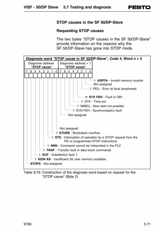
STOP causes in the SF 50/DP-Slave
Requesting STOP causes
The two bytes "STOP causes in the SF 50/DP-Slave"provide information on the reasons why the SF 50/DP-Slave has gone into STOP mode.
Diagnosis word "STOP cause in SF 50/DP-Slave", Code 4, Word n + 5Diagnosis address
"STOP cause"Diagnosis address + 1
"STOP cause"7 6 5 4 3 2 1 0 7 6 5 4 3 2 1 0
1: ASPFA - Invalid memory moduleNot assigned
1: PEU - Error at local peripherals
1: SYS FEH - Fault in DB1
1: ZYK - Time-out
1: NINEU - New start not possible
1: SYN FEH - Synchronisation fault
Not assigned
Not assigned
1: STUEB - Blockstack overflow
1: STS - Interruption of operation by a STOP request from the PG or programmed STOP instructions
1: NNN - Command cannot be interpreted in the PLC
1: TRAF - Transfer fault in data block commands
1: SUF - Substitution fault 1:
1: KEIN AS - Insufficient S5 user memory available.
STOPS - Not assigned
Table 5/19: Construction of the diagnosis word based on request for the "STOP cause" (Byte 2)
VISF - 50/DP Slave 5.7 Testing and diagnosis
9706 5-71

User-specific diagnosis
The user-specific diagnosis can be prepared for col-lection by the DP-Master through the user program inthe SF 50/DP-Slave. The user-specific diagnosis canbe specified freely, in compliance with the standardPROFIBUS-DP (DIN 19245, part 3), in 6 bytes.
These 6 bytes are in the SF 50/DP-Slave, containedwithin the EPO in the peripheral words PW 250, 252, 254.
Example:
:L KF 1:T PW 250
User-specific diagnosis transfer to DP master
At the cycle control point of the SF 50/DP-Slave, thecommunications processor copies the diagnosis of theSF 50/DP-Slave, including the user-specific diagnosisfrom the EPO into its DP transmitting buffer (chapter5.2). Only if the user-specific diagnosis has changedsince the last interrogation of the SF 50/DP-Slave viathe PROFIBUS-DP will the DP-Master collect it duringthe next SF 50/DP-Slave interrogation.
Evaluation
Evaluation is possible: • Within the user program of the CPU which is
connected to the DP-Master or • using the PG "STATUS" function
VISF - 50/DP Slave 5.7 Testing and diagnosis
5-72 9706

User-specific diagnosis
If no user-specific diagnosis is prepared for the DP-Master, the 6 bytes in the SF 50/DP-Slave user pro-gram must be filled with "0".
Load L KF 0 "0"T PW 250 6 bytes user-specificT PW 252 diagnosis is set to "0"T PW 254
PLEASE NOTEThe user-specific diagnosis will be automaticallydeleted during a STOP⇒RUN transition in the SF 50/DP-Slave (reset to "0"). Therefore, it must beensured within the SF 50/DP-Slave user programthat the user-specific diagnosis is updated at thecycle control point. For data consistency reasons,the user-specific diagnosis in OB13 must not bechanged.
VISF - 50/DP Slave 5.7 Testing and diagnosis
9706 5-73

5.7.2 Function of the BF LED on the SF 50/DP-Slave
The bus fault LED will stay lit until the DP-Master isused to correctly parameterise and configure the SF 50/DP-Slave.
The BF LED will light up again if: • Incorrect parameterization or configuration data
has been received from the DP-Master, • the response monitoring in the SF 50/DP-Slave is
timed-out or • the communications processor in the SF 50/DP-
Slave is faulty.
The following table describes the significance of theBF LED. The construction of the diagnosis byte"status reports" and "error reports" can be found inchapter 5.7.3.
VISF - 50/DP Slave 5.7 Testing and diagnosis
5-74 9706

EXCEPTIONIf the parameter block DPS of the SF 50/DP-Slaveis set to inactive using the comment character (#),then the BF LED does not light up.
BF LED lights up and ... Significance RemedyIn the diagnosis byte ”status messages” Bit 5=0
So far no commissioninghas occured through theDP-Master, i.e. The DP-Master has not received aparameterization andconfiguration message.
Wait for or implement thecommissioning with theDP-Master.
In the diagnosis byte ”error reports” Bit 0=1
Parameterization faultoccured, i.e. theparameterization messagesent by the DP-Master isfaulty.
Change theparameterization in the DP-Master (⇒equipmentmanual ”ET 200 Distributed I/O System”)
In the diagnosis byte ”error reports” Bit 1=1
Configuration fault occured,i.e. the configuration sentby the DP-Master does notagree with the DB1parameter ”DPAE”.
Change the configuration inthe DP-Master (⇒chap. 4)or change configuration inthe DB1 (⇒chap. 5.4).
In the diagnosis byte ”error reports” Bit 2=1
Response monitoring in SF 50/DP-Slave haserminated (chap. 5.7).
Check the bus cable andDP-Master for any defects.
In the diagnosis byte ”error reports” Bit 3=1
Communications processorin SF 50/DP-Slave is faulty.
Read system data 101.
Table 5/20: Significance of the BF LED
VISF - 50/DP Slave 5.7 Testing and diagnosis
9706 5-75

5.7.3 Fault diagnosis in the user program of the SF 50/DP-Slave
Two bytes are available for diagnosis in the user pro-gram of the SF 50/DP-Slave. These bytes are con-tained in the extended peripheral area - inputs (EPI):• Diagnosis byte "status reports"; held in PY 254
and • Diagnosis byte "error reports"; held in PY 255
Access to these diagnosis bytes in the user programis read-only. The bytes must be linked with a loadoperation in the user program of the SF 50/DP.
The following operations, value ranges and dataranges can be used to access these bytes:
Loading fromEPI
e.g. Transferringto user program
Example Explanation
L PY 254 ... 255/L PW 254
T IB/QB/IW/OW/ PY/PW/FY/FW/ DL/DR/DW
L PW 254T FW 210
The peripheral Word254 is transferred fromthe EPI to the flag Word210. FY 210= diagnosisbyte ”status messages”;FY 211= diagnosis byte”error reports”
Table 5/21: Access to the diagnosis byte of the SF 50/DP-Slave in the user program
VISF - 50/DP Slave 5.7 Testing and diagnosis
5-76 9706

After the SF 50/DP-Slave has been booted up on thePROFIBUS-DP, the following default values are set inthe diagnosis bytes:• Diagnosis byte "status reports"
00H = 0000 0000B • Diagnosis byte "error reports"
10H = 0001 0000B
The diagnosis bytes are updated at the cycle controlpoint of the SF 50/DP-Slave.
VISF - 50/DP Slave 5.7 Testing and diagnosis
9706 5-77

Diagnosis byte "status messages"
Only when Bit 5 = 1 in the following diagnosis byte,i.e. the commissioning of the SF 50/DP-Slave on theSINEC L2-DP has occured, then the remaining"status messages" bits are valid.
Diagnosis address "status messages"
7 6 5 4 3 2 1 0 PY 254
CLEAR DATA *0: Communications processor is operating normally.1: Receiving data are deleted in the SF 50/DP-Slave (control command with Clear-Data = 1 received).
Not assignedNot assigned
User Prm *0: No user-specific parameterization data available. 1: User-specific parameterization data available.
Watchdog 0: Response monitoring is not activated. 1: DP-Master has activated the response monitoring in the communications processor with a parameterization message.
Commissioning0: So far no commissioning through the DP-Master, no configuration or para-
meterization message has been received by the DP-Master (remaining Bits are invalid).1: Commissioning with the DP-Master has occured, the correct configu-
ration and parameterization has occured with the DP-Master.
Cycle (Evaluation is only useful if the transmitting and receiving data in the extended peripheral areas are available.)00: PLC and DP cycles are running synchronously.01: The DP cycle is faster than the PLC cycle, i.e. DP-Master data areupdated more frequently than the data in the control processor of the SF 50/DP-Slave.10: The PLC cycle is faster than the DP cycle, i.e. the data in the control processor of the SF 50/DP-Slave are updated more frequently than the DP-Master data.11: Not possible
* Bit is deleted at the next cycle control point.
Table 5/22: Structure of the diagnosis byte "status messages"
VISF - 50/DP Slave 5.7 Testing and diagnosis
5-78 9706

"Error reports" diagnosis byte
Diagnosis address "error reports"
7 6 5 4 3 2 1 0 PY 255
Parameterisation0: Correct parametrisation 1: Parameterization fault occured, i.e. the parameterization message sent by the DP-Master is faulty
Configuration 0: Correct configuration 1: Configuration fault occured, i.e. the configuration sent by the
DP-Master does not agree with the DB1 parameter ”DPAE”.
Monitoring0: Response monitoring is not timed-out1: The response monitoring set in the communications processor is timed-out, i.e. within this period no messages have been re- ceived from the DP-Master.
Possible causes: - Interruption of the bus cable or - Defect in the DP-Master
Sign of life0: The communications processor in the SF 50/DP-Slave is functional.1: The communications processor in the SF 50/DP-Slave is no longer registering.
DP data0: The receiving data in the SF 50/DP-Slave are valid.1: The receiving data in the SF 50/DP-Slave are invalid.
Parameter block ”DPS:”0: Parameter block ”DPS:” activated in the DB1.1: Parameter block ”DPS:” not activated in the DB1.
Not assigned
Table 5/23: Construction of the "error reports" diagnosis byte
VISF - 50/DP Slave 5.7 Testing and diagnosis
9706 5-79

5.7.4 Failure behaviour of the SF 50/DP-Slave
As a DP slave, the SF 50 has the following failuremonitoring tools available for evaluation: • Signs of life from the control processor in the
SF 50/DP-Slave • DP slave response monitoring through the
DP-Master
Signs of life from the control processor in the SF 50/DP-Slave
Once the PROFIBUS-DP interface is booted up, thecommunications processor of the SF 50/DP-Slavestarts a monitoring period of 0.5 s. After a maximum0.5 s the failure of the control processor is recognisedby the communications processor and transmitted tothe DP-Master.
Special points: • A RUN-STOP transition in the SF 50/DP-Slave will
terminate the monitoring period.• A STOP-RUN transition in the SF 50/DP-Slave will
start the monitoring period. • This period will be re-triggered at the cycle control
point (also when the OB31 is called up).
VISF - 50/DP Slave 5.7 Testing and diagnosis
5-80 9706

DP slave response monitoring through the DP-Master
The response monitoring is activated by COM ET 200in the DP-Master for a PROFIBUS-DP bus system.
(⇒ Equipment manual "ET 200 Distributed I/O System").
As a DP slave, the SF 50 receives a parameterizationmessage from the DP-Master, which states: • whether the response monitoring has been acti-
vated and • which monitoring period should be set by the PLC.
If the response monitoring has been activated, thenthe PLC starts the monitoring period.
Each message from the DP-Master triggers the moni-toring period. Each new parameterization messagefrom the DP-Master can deactivate the responsemonitoring or change the monitoring period.
If the monitoring period is timed-out then in the diagnosis byte for error reports, Bit 2 is set to =1. Thismeans that no message was received from the DP-Master within the monitoring period.
Possible causes are: • an interruption in the bus cable or • a defect in the DP-Master
The receiving data in the extended peripheral area ofthe SF 50/DP-Slave are deleted, i.e. reset to "0". TheSF 50/DP-Slave continues to remain in the RUN oper-ating condition.
VISF - 50/DP Slave 5.7 Testing and diagnosis
9706 5-81

VISF - 50/DP Slave 5.7 Testing and diagnosis
5-82 9706
Programmable valve terminalswith
Control block SB 50 / SF 50
Part 6: APPENDIX
GLOSSARYLITERATURE REFERENCES
INDEX
PN
350
649

6.1 GLOSSARY
PN
350
649
VISB/SF- 50 6.1 Glossary
9706 6-1

VISB/SF- 50 6.1 Glossary
6-2 9706

AActive slave
Active slaves can, when they are permitted to trans-mit, send data to other slaves and request data fromother slaves (= Master station).
Actuator Working element of a controller. Movement is pro-duced by an actuator (cylinder, motors) or other oper-ations are initiated (electrical, mechanical, etc.). Sig-nalling equipment such as lamps are also actuators.
Actuator devicesThe actuator devices include the machines and equip-ment used in control technology to directly act on themass flow. Examples include cylinders for linearmovements, motors for rotary movements and valvesfor gas flows, etc. Depending on the functional view,final control elements can also be classed as actuatordevices: the cylinder is controlled by a valve, etc. If acontrol device is examined, for example a PLC, thenthe valve is seen as an actuator device. If the move-ment is examined, then the valve is seen as a proces-sor device.
Address identifierCharacter / number combination used to identify anET 200U peripheral module in the COM ET 200.
Address selector switchThe field bus address of the terminal is set in the ad-dress selector switch on the field bus nodes of thevalve terminal.
VISB/SF- 50 6.1 Glossary
9706 6-3
Autarkical(Greek: self-sufficient) Each programmable valve terminal has a built-in PLC(programmable logic controller) and is therefore inde-pendent of a higher-order master. Once a programm-able valve terminal (SB 50 or SF 50) has been com-missioned, it is operational without requiring any auxi-liary equipment and is therefore autarkical.
Bbar
Unit of pressure, used in addition to the official SI unitpascal (Pa) in engineering. 1 bar equals 105 Pa or 0.1MPa (megapascal).
BaudUnit for the speed of data transmission. 1 baud = 1 bit/s
Baud rateThe baud rate indicates the speed of data trans-mission. Transmitter and receiver must be set to thesame baud rate, since otherwise errors can occur dur-ing transmission. Technical baud rates are between75 bauds and several megabauds.
BusCommon conductor path connecting all slaves, withtwo definite end points.
Bus segment→ Segment
VISB/SF- 50 6.1 Glossary
6-4 9706

Bus usersUnits which send, receive or amplify data over thebus, e.g. master station, slave station, repeaters, etc..
CCommand set
Includes all commands with which programmablevalve terminals can be programmed using the lan-guages STL, LDR and CSF. The command set has adifferent extent for each of the different languages.
ComponentCombination of elements which form a group, called acomponent, which is part of an overall plant, machineor equipment unit.
Control blockThe control block is the "intelligent part" of a pro-grammable valve terminal and contains the elec-tronics (PLC) which make a standard valve terminalprogrammable. The control block is designed in ac-cordance with protection class IP 65. This means thatthe integrated PLC can be used directly on a ma-chine. The main characteristics of the integrated PLCinclude integrated RAM und EEPROM; programmableusing STL, LDR and CSF with the programming soft-ware SIMATIC STEP 5; flags, timers, counters andother devices are available. The PLC has the samefunctionality as the SIMATIC small control system.The number of available or addressable physical I/Osare as follows:
VISB/SF- 50 6.1 Glossary
9706 6-5
• Without PROFIBUS-DP field bus module- max. 56 local inputs and 64 local outputs
addressable• With PROFIBUS-DP field bus module
- max. 56 local inputs and 64 local outputsaddressable
- max. 118-byte inputs and 120-byte outputs fordigital and analogue peripherals addressable(centrally controlled slaves)
CP 5410 S5-DOS/STPG interface for the connection to SINEC L2, andSINEC L2-DP.
CSF (Control System Flowchart)Graphic description method for sequence-orientatedcontrol tasks.
DData transfer
Transfer of data between different processors or mo-dules, or from the processor to the peripheral devices.
DiagnosisRecognition, localisation, classification, display, furtherevaluation of faults, interruptions and reports.
Diagnosis offers monitoring functions which run auto-matically while the equipment is in operation.
Diagnosis byteThe diagnosis byte offers important information con-cerning the condition of the connected peripherals incases of malfunction (for example a valve terminalwith field bus node 9 (PROFIBUS-DP)). Diagnosis
VISB/SF- 50 6.1 Glossary
6-6 9706

bytes are queried by the PLC user program via thefield bus. The condition information obtained in thismanner can be evaluated in the STEP 5 program.This means that, for example, errors can be displayedin (clear) text on a text display.
Diagnosis interface(Also called PG interface) The diagnosis interface isthe connection from the programmable valve terminalto the following devices:
Programmer (PG710 ...... with PLC interface TTY)
Control unit (unit for operation and monitoring, suchas OP5 and OP15, terminal)
The diagnosis interface complies with the internationalstandard TTY/RS 422. It is a passive current element.
DP StandardThe DP Standard is the bus protocol of the remoteperipheral system ET 200 as set out in the draft stan-dard DIN E 19245, part 3.
DP SiemensDP Siemens is the bus protocol developed bySiemens. In co-operation with the PROFIBUS user or-ganisation, this bus protocol has been expanded intoan open and manufacturer-independent system. Thecurrent expanded bus protocol has been put forwardto the "Deutschen Elektrotechnischen Kommision"(DKE) and accepted as the national draft standardDIN E 19245, part 3, (→ DP Standard)
VISB/SF- 50 6.1 Glossary
9706 6-7

EEEPROM (Electrically Erasable Programmable Read Only Memory)
Read-only memory (ROM), the content of which canbe deleted electrically, then reprogrammed with newinformation. EEPROMs can be programmed up to10000 times. This means that the user program of theprogrammable valve terminals can be loaded up to10000 times by the PG, using the COMPRESS func-tion, into the EEPROM. The operands of a program,which are "saved" in the EEPROM when the opera-ting voltage of the RAM fails, can be pro-grammed/saved up to 310000 times thanks to a pecu-liarity of the operating system in the programmablevalve terminals.
ET 200Bus for the connection of remote peripherals to theautomation tools S5-95, S5-115U ... S5-155U, pro-grammable valve terminals with SF 50 or a suitablemaster. ET 200 is characterised by rapid reactiontimes, as only few data (bytes) are transferred.
ET 200 is based on the PROFIBUS standard (DIN 19245, part 1) and the draft standardPROFIBUS-DP (DIN E 19245, part 3).
ET 200 operates in accordance with the master-slaveprinciple. Masters can include the master interfacecomponent IM 308-B, a programmable valve terminalwith SF50 or a host which conforms to the CP 5480-DP.
Slaves can include the remote peripherals ET 200B,ET 200C, ET 200U or valve terminals with field busnode 9. In addition remote peripheral devices can beconnected if they contain an SPM module.
VISB/SF- 50 6.1 Glossary
6-8 9706

Exhaust airCompressed air from a pneumatically operated devicewhich is discharged to the atmosphere, either directlyor through an exhaust air filter. In pneumatic controldevices, all elements must contain exhaust vents(ventilation vents) so that the valves or other workingelements can reach all available settings. Closed ex-haust vents nearly always cause operating malfunc-tions. The exhaust air from a valve terminal is col-lected together into a common exhaust network (col-lection channel). This requires sufficient flow-throughvolumes and, with linked systems, non-return valvesmust be fitted for mutual separation.
FField bus
Serial bus system for information exchange betweenspatially distant parts of a process or technical pro-duction processes. Remote stations of the processhave sensors, actuators and control devices with dif-fering levels of complexity. The principal advantagesof using a field bus are the reduction in parallel wiring,the reduced workload of higher-order control devicesthanks to remote preliminary processing and the elimi-nation of difficulties of analogue transmissions duringconversion to digital format in the field bus station.
Characteristics of a typical field bus include:• master-slave, command-response modes.• interference-immune transmission medium. Two-
wire copper cable, screened and twisted. Signaltransmission in push-pull mode (Standard RS 485)and electrical isolation of the bus slaves. In the fu-ture, optical bus systems will be used increasingly.
• high transfer rates up to several MBauds.• spatial extension up to several kilometers.
VISB/SF- 50 6.1 Glossary
9706 6-9
Field bus addressAddress of a field bus slave on the PROFIBUS-DP,for example a valve terminal with field bus node 9.This address is required in order to identify the slavesin the field bus system. The field bus address is setfor the specific field bus slave using the address se-lector switch.
Field bus moduleField bus module makes it possible to connect anelectronic controller (e.g. PLC, PC, programmablevalve terminal) to a field bus system. The field busmodule must be set to the specific field bus, so that itsupports the physical and logical functions of the spe-cific bus system. The field bus interface for thePROFIBUS-DP of the programmable valve terminal isfitted in the node housing and permits up to 16passive and one active slave to be connected.
Flow rateVolume of gases or liquids that flow through a body orcomponent (e.g. valve) in a specific period.
IIP 20
Protection class as specified in DIN 40050. Protectionagainst finger contact and against penetration by solidforeign bodies of over 12 mm diameter.
IP 65Protection class as specified in DIN 40050. Full pro-tection against contact, protection against penetrationby dust and against entry of water spray from all di-rections.
VISB/SF- 50 6.1 Glossary
6-10 9706
LLDR (Ladder diagram)
Graphic method of describing link-oriented control tasks, based on the electrical circuit diagram.
MManual override (MO)
Plunger on the pilot valve, e.g. a solenoid valve,which can be used to operate the valve without anelectrical signal. An existing electrical signal, however,cannot be cancelled.
Master interface componentComponent for remote construction. The IM 308-Bmaster interface component is used to "connect" theremote peripherals to the PLC.
The programmable valve terminals with SF 50 containa master interface in the control block.
Master-slave processBus access process where only one slave is activeand all other slaves are passive at any one time.
VISB/SF- 50 6.1 Glossary
9706 6-11

NNominal pressure
The pressure to which specific values are relatedwhen the device is working under nominal operatingconditions. This is usually the hydraulic or air pres-sure, in relation to the manufacturer’s values given forflow rate, switching rate, etc.
Nominal widthThe nominal width provides information concerningthe smallest cross-section in the main flow of thevalve. It is expressed in mm.
OOperand
The control instruction of a program for a program-mable controller is usually sub-divided into operationand operand: The operation states what task is to bedone and the operand states with what it is to bedone. The operand can be the address of an I/O mo-dule or an internal controller address (e.g. a flag,timer, counter, etc.).Example: with the instruction: A I3.2"A" is the operation (logic AND), "I3.2" is the operand.
OperationPart of the command set of a PLC
Operating pressureThe pressure at which a pneumatic or other pres-surised device is normally operated. The operatingpressure may fluctuate between specified limits. Ifthese limits are exceeded or not reached, then theequipment malfunction is to be expected.
VISB/SF- 50 6.1 Glossary
6-12 9706

Operating pressure range(abbreviated to pressure range) This is the range be-tween the lowest possible or highest permissableoperating pressure for the safe operation of an ele-ment or system.
Operating systemThe operating system is an integral part of every com-puter system. It determines the performance and fieldof application of a system. The operating system of aprogrammable valve terminal controls the processor,manages the user and program memory and the pe-ripheral devices connected to the diagnosis interface(PT, terminal, display and operating device).If the programmable terminal also includes aPROFIBUS-DP field bus interface, then the operatingsystem also controls all passive field bus slaves andcontrols the data traffic via the field bus.
PPassive slaves
Passive slaves can only exchange data with an activeslave after being requested to do so (= Slave station).
PeripheralsExternal devices separate from the controller, but con-nected to the control system, and used for the input,output, display or storage of data (e.g. terminal,printer, floppy disk drive).The (remote) peripherals are addressed by the pro-grammable valve terminal via the PROFIBUS-DP fieldbus.
PII(Refer to process image)
VISB/SF- 50 6.1 Glossary
9706 6-13

PIO(Refer to process image)
PROFIBUSPROcess FIeld BUS, German process and field busstandard, set out in the PROFIBUS Standard DIN 19245.
This standard provides the functional, electrical andmechanical properties for a serial bit field bus system.
PROFIBUS-DPDraft standard PROFIBUS-DP (DIN E 19245, part 3),on which the ET 200 remote peripheral system isbased.
Process image(PIO = Process image of outputs, PII = Processimage of inputs).To achieve time-specific switching behaviour of the in-puts and outputs in a controller, they are only read/setat a specific time. In the operating system of the pro-grammable valve terminal with SB/SF 50 this alwaysoccurs at the end of a program.
Programmable valve terminalsThe programmable valve terminal consists of: • A standard valve terminal• A control device (control block)
The control block contains the entire control elec-tronics, i.e. programmable logic controller, memorycomponents (RAM and EEPROM) and the operatingsystem together with the command interpreter. Thisenables a programmable valve terminal to solve auto-mation tasks autarkically on site (see also valve termi-nal and valve/sensor terminal).
VISB/SF- 50 6.1 Glossary
6-14 9706

Program moduleFor ease of programming and to reduce the workloadof the user program, frequent command sequences ortext messages are handled by the program module(sub-programs).Program modules are called up by the program inoperation. The programmable valve terminal withSB/SF 50 can manage up to 256 program modules inthe user memory.
ProtocolAgreement which allows two or more items of equip-ment to communicate with one another. For instance,a protocol establishes which control characters indi-cate the beginning and end of a text entry.
RRAM (Random Access Memory)
Memory with random access to data. The contents ofthis kind of memory can be read, deleted or modifiedby a computer. Access to data in memory is gainedby specifying the address. This makes it possible togain rapid access at all times to data stored in thememory. Since RAM loses its storage ability whenpower is switched off, its contents have to be trans-ferred to a different storage medium (EEPROM, harddisk) or backed up on battery storage to ensure thatno data are lost.
Relocatable(Relocatable = variable location; opposite: absolute)In general terms, a program written in a high-levellanguage (LDR, STL) can be relocated to any positionin the memory (relocatable). If fixed (absolute) ad-dresses are defined in machine language for a givenprocess, a program of this kind is only able to run atone memory location.
VISB/SF- 50 6.1 Glossary
9706 6-15

RemanentRemanent operands do not change their status whenthe control device is switched off, then switched backon.
A part of the operands in the programmable valve terminal is saved in the EEPROM if the operating vol-tage fails. When the power is switched back on, thisdata can be called up again unchanged by the user.The non-residual (unsaved) operands lose their con-tents when the operating voltage is switched off.
Remote-controlledA remote-controlled field bus system uses slaveswhich have "independent intelligence" (active slaves).This includes e.g. the SIMATIC unit AG95U with afield bus module PROFIBUS-DP. Although a master,for example a programmable valve terminal with SF 50, is in control of the data traffic via the field busand all actions of the passive slaves (see also central-controlled), the active slaves control their local in-puts/outputs themselves (autarkical operation).
Remote peripheralsThese are input and output modules which are re-motely accessed by the CPU. The remote peripheralin the SIMATIC family is the remote peripheral systemET 200. In this system the remote peripherals are:- ET 200B,- ET 200C- ET 200U - valve terminals with field bus node 9 or external devices which contain an SPM module.
RepeaterUnit used to amplify bus signals and segment coup-lings over large distances.
VISB/SF- 50 6.1 Glossary
6-16 9706

SSeal
Components or systems for the separation of twospaces with differing pressure levels or differentmedia. They are used to prevent the entry or exit ofgases, liquids or foreign bodies (dust, etc.).
SegmentThe bus lines between two terminating resistors forma segment. A segment can contain 0...32 bus slaves.Segments can be coupled via a → repeater.
SensoricsAll the functional elements in control technology whichare used for the recording, modification, preparationand conversion of signals.
SensorUnit that collects information (measurements) from a process and transfers it to the controller. Sensorsrecord e.g. geometric data such as length and path,the distance of objects, the volume of containers,limits of power, pressure, humidity or temperature andmovement-related data such as speed, rotationalspeed or flow rate, and send this information to theprocessing section of the controller for further pro-cessing. The following physical measurements areusually used: resistance (potentiometer, straingauges, resistance thermometer), induction (inductiveproximity switch, pressure gauge), capacitance (capa-citive proximity switch, pressure gauge), piezoeffect(piezoelectrical or piezoresistive dynamometer),photoconductivity (photoresistor)
Names such as detector, pick-up, generator, conver-ter or cell are all used today as synonyms for sen-sors.
VISB/SF- 50 6.1 Glossary
9706 6-17
Short circuitShort circuit is an accidental electrical connection oflow resistance between two conductors under opera-ting voltages, when there is no effective resistance inthe faulty circuit.
Short circuit-proofShort circuit-proof denotes an operating medium thatcan resist the thermal and dynamic effects of any short-circuit current expected at the point of installation.
SilencersSilencers are used to reduce noise at the exhaustconnections of valves and valve terminals. Reducingthe air speed also results in noise reduction. Silencersgreatly reduce ventilation noise without causing anysignificant effect on the pump rod speed.
SINEC L2Bus system; networks PROFIBUS-compatible auto-mation systems and field devices at the cell and fieldlevel.
SINEC L2-DPBus system SINEC L2 with the DP protocol. DP stands for Decentralized (remote) Peripherals.
Solenoid valveValve with electromagnetic operation. In electropneu-matic or electrohydraulic systems, the solenoid valveacts as the interface between the electronics andpneumatics or hydraulics.
STL (Statement List)Programming language for programmable control de-vices and programmable valve terminals, which canbe used to program all logic operations and pro-cesses with its command set. A statement list (STL)can contain step-oriented as well as link-orientedcomponents.
VISB/SF- 50 6.1 Glossary
6-18 9706

Status byte(Refer to diagnosis byte)
Station numberEach ET 200 bus slave must have a station number. - The PT or the handhald ET 200 are addressed with
the station number "0",- A Master has the station number "1" or "2",- A Slave station has a station number from the
range 3...124.- Exception: an ET 200B has a station number in the
range 3...99.
TTerminating resistor
Resistor for power matching of the bus cables; termi-nating resistors are usually required on the cable andsegment ends.
UUser program
A program written by or for a user for a control sys-tem, e.g. a PLC (Programmable Logic Controller) withwhich a specific control task is executed for the user.User programs are written in the programmable valveterminals using STL, LDR or FND and stored in theEEPROM.
VISB/SF- 50 6.1 Glossary
9706 6-19
VValve
In pneumatics, elements for controlling pressure andcompressed air. These differentiate between two-wayvalves, discharge valves, flow valves and reversevalves.
The programmable valve terminals can be fitted withtwo-way valves with a spring-return device, with pulseresponse or with neutral position (closed, ventilated orexhausted). All valves are pneumatic pilot controlledvalves. This means that the electrical signal switchesa small valve, which in turns controls the main valve.This results in smaller control currents of between 55 mA and ca. 350 mA, depending on the valve size.The supply of pilot control air is taken in part from themain control air and is in part separately supplied. Aseparate supply is always required if the supplypressure is p < 3 bar.
Valve/sensor terminalModule consisting of pneumatic and electrical compo-nents. It is an alternative designation for a valve ter-minal with additional electrical inputs and outputs.This type of valve terminal can considerably reduceinstallation costs. A valve/sensor terminal already con-tains the following components: # sockets for valves,# electrical outputs (e.g. for valves of other nominalwidths or for lamps) # electrical inputs (e.g. for sen-sors or pushbuttons).
FESTO valve/sensor terminals are controlled by:• Field bus
• With integrated PLC
VISB/SF- 50 6.1 Glossary
6-20 9706
6.2 Index
PN
350
649
VISB/SF- 50 6.2 Index
9706 6-23
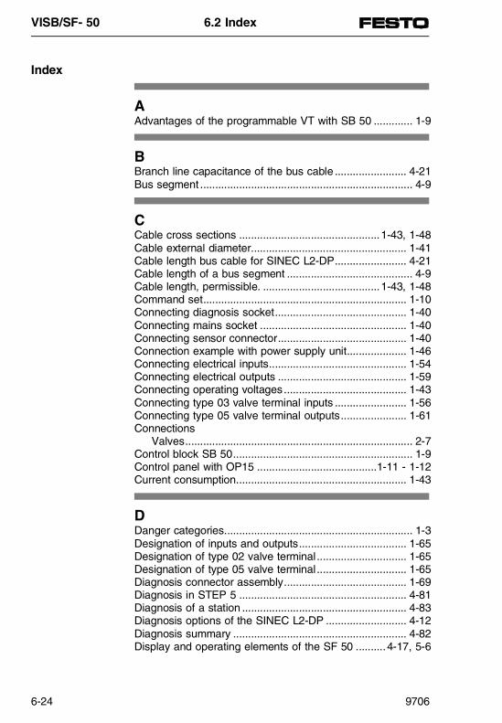
Index
AAdvantages of the programmable VT with SB 50 ............. 1-9
BBranch line capacitance of the bus cable ........................ 4-21Bus segment ....................................................................... 4-9
CCable cross sections ...............................................1-43, 1-48Cable external diameter.................................................... 1-41Cable length bus cable for SINEC L2-DP........................ 4-21Cable length of a bus segment .......................................... 4-9Cable length, permissible. .......................................1-43, 1-48Command set.................................................................... 1-10Connecting diagnosis socket............................................ 1-40Connecting mains socket ................................................. 1-40Connecting sensor connector........................................... 1-40Connection example with power supply unit.................... 1-46Connecting electrical inputs.............................................. 1-54Connecting electrical outputs ........................................... 1-59Connecting operating voltages......................................... 1-43Connecting type 03 valve terminal inputs ........................ 1-56Connecting type 05 valve terminal outputs...................... 1-61Connections
Valves............................................................................ 2-7Control block SB 50............................................................ 1-9Control panel with OP15 ........................................1-11 - 1-12Current consumption......................................................... 1-43
DDanger categories............................................................... 1-3Designation of inputs and outputs.................................... 1-65Designation of type 02 valve terminal.............................. 1-65Designation of type 05 valve terminal.............................. 1-65Diagnosis connector assembly......................................... 1-69Diagnosis in STEP 5 ........................................................ 4-81Diagnosis of a station ....................................................... 4-83Diagnosis options of the SINEC L2-DP ........................... 4-12Diagnosis summary .......................................................... 4-82Display and operating elements of the SF 50 ..........4-17, 5-6
VISB/SF- 50 6.2 Index
6-24 9706
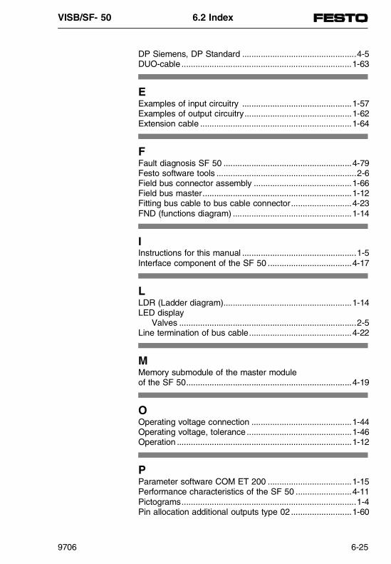
DP Siemens, DP Standard .................................................4-5DUO-cable .........................................................................1-63
EExamples of input circuitry ...............................................1-57Examples of output circuitry..............................................1-62Extension cable .................................................................1-64
FFault diagnosis SF 50 .......................................................4-79Festo software tools ............................................................2-6Field bus connector assembly ..........................................1-66Field bus master................................................................1-12Fitting bus cable to bus cable connector..........................4-23FND (functions diagram) ...................................................1-14
IInstructions for this manual .................................................1-5Interface component of the SF 50 ....................................4-17
LLDR (Ladder diagram).......................................................1-14LED display
Valves ............................................................................2-5Line termination of bus cable............................................4-22
MMemory submodule of the master module of the SF 50.......................................................................4-19
OOperating voltage connection ...........................................1-44Operating voltage, tolerance .............................................1-46Operation ...........................................................................1-12
PParameter software COM ET 200 ....................................1-15Performance characteristics of the SF 50 ........................4-11Pictograms...........................................................................1-4Pin allocation additional outputs type 02 ..........................1-60
VISB/SF- 50 6.2 Index
9706 6-25

Pin allocation for operating voltage.................................. 1-45Pin allocation inputs type 02 ............................................ 1-55Pin allocation inputs types 03/05...................................... 1-56Pin allocation of the SINEC L2-DP interface ..................... 5-6Pin allocation outputs types 03/05 ................................... 1-61Pin assignment of the SINEC L2-DP interface ................ 4-19Possible transfer rates of SINEC L2-DP.......................... 4-11Potential compensation .................................................... 1-46Power supply unit ............................................................. 1-45PROFIBUS-DP.................................................................... 4-6Programmable valve/sensor terminals ............................... 1-6Programmer ...................................................................... 1-14Programming..................................................................... 1-12Programming software STEP 5........................................ 1-14Protective earthing ............................................................ 1-46
RReaction times in the ET 200 system .............................. 4-93RS 232 interface ................................................................. 2-6
SSF 50 system summary...................................................... 4-3SF50 as master module for ET 200................................... 4-3SINEC L2 bus cable connector ........................................ 4-15SINEC L2 bus cable connector of the SF 50 .................. 4-21SINEC L2-DP, the PROFIBUS-DP from Siemens........... 4-11Slave stations.................................................................... 1-12STL (Statement List)......................................................... 1-14Summary - valve terminal type 02 ................................... 1-16Summary - valve terminal type 03 ................................... 1-17System summary ................................................................ 1-9SB 50 system structure .................................................... 1-10
TTerminal summary ............................................................ 1-16
VValves.................................................................................. 2-5
VISB/SF- 50 6.2 Index
6-26 9706

Fitting instructions for fieldbus connector FBS-SUB-9-GS-9, PN. 18529
PN
346
663
/ P
V-D
IP /
Rb
Tubing clip
Terminal block
Fig. 1: Individual components of plug
Fitting sequence
1. Insert a seal (7) in the bottom cover (9) and top cover (6).
2. Insert the PCB (8) in the guide in the bottom cover (9). Secure thePCB to the bottom cover with the countersunk screws (10).
3. Screw the lower part of the threaded fitting (5) into the top cover (6) as far as it will go. Thread the union nut (1), the clamping ring (2) and the cone seal (3) onto the cable.
4. Feed the cable through the top cover.
5. Trim the insulation from the bus cable as shown in Fig. 2 and connectit to the terminal block.
6. Push the top cover (6) over the PCB and lock it together with the bot- tom cover. Fit the cone seal and clamping ring into the lower part of
the threaded connection and secure with the union nut.
7. Insert the screws (4) into the plug housing until the limit stop and then,applying pressure, use a screwdriver to screw them into the bottomcover until they project by 1 to 2 mm.
Important: - The terminating resistors must be connected to the start and end of
the segment (→ fig. 4).
- If the bus cable is looped through, the terminating resistors must notbe connected (→ fig. 3).
- At the start and end of the segment, one cable exit must be closed bymeans of the plug seal (→ fig. 5).
Plug seal
Fig. 5: Sealing the plug
105
6
Bare braided screenmust be clamped under tubing clip
Fig. 2: Preparing the cable
Bus plug connector with looped-through bus cable.Switch position OFF (Terminating resistor not connected)
Fig. 3: Terminating resistor OFF
Bus plug connector at start orend of segment.Switch position ON (Terminating resistor connected)
Fig. 4: Terminating resistor ON
VISB - 50 Fitting instruction
FESTO KG 73734 Esslingen Tel 0711 / 347-0

Fitting instructions for plug IP 65, S-SUB-15-GS-9, PNo. 18574, 18578
PN
348
936
/ P
V-I
IP /
Rb
/ Dec
.95
2 models: - Solder connections (18578)- Crimp connections (18574)
Fig. 1: Individual components of plug
Contact allocation for 15-pin sub-D plug. Valid for: ISF 50-02
ISB 50-02ISF 50-03ISB 50-03
Contact Number Contact designation
1 Screen
2 TTY IN- (grey-blue)
6 TTY OUT+ (brown)
7 TTY OUT- (yellow)
8 Screen
9 TTY IN+ (white)
Fig. 2: Contact allocation for SB/SF 50
Fitting sequence
1. Insert a seal (7) in the bottom cover (9) and top cover (6).
2. Screw the lower part of the threaded fitting (5) into the top cover (6)as far as it will go.
3. Thread the union nut (1), the clamping ring (2) and the cone seal (3)onto the cable.
- ø 6...9 mm one clamping ring (2) - ø 4.5...6 mm two clamping rings (2)
4. Feed the cable through the top cover.
5. Fit the sub-D plug (11) to the bottom cover (9) with the countersunkscrews (10).
6. Trim the insulation from the cable. Fit the individual cores with crimpcontacts and snap-fit contact pins into the sub-D plug in accordancewith the contact allocation. OR Trim the insulation from the cable. Solder the individual cores intothe sub-D plug in accordance with the contact allocation.
7. Fit together the top cover (6) and the bottom cover. Insert the cone seal and clamping ring into the lower part of the threaded connector and secure with the locking nut.
8. Insert the screws (4) into the plug housing as far as they will go and,applying pressure, use a screwdriver to screw them into the bottomcover until they project by 1 to 2 mm.
View in direction of arrow
VISB - 50 Fitting instruction
FESTO AG & Co KG 73734 Esslingen Tel 0711 / 347-0