CPX terminal - Festo · TwinCAT ® is a registered ... CPX terminal Complete system consisting of...
120
Manual Electronics CPX bus node Type CPX−FB38 Network protocol EtherCAT CPX terminal Manual 562 525 en 0804NH [733 639]
Transcript of CPX terminal - Festo · TwinCAT ® is a registered ... CPX terminal Complete system consisting of...

Manual Electronics
CPX bus node
Type CPX−FB38
Network protocolEtherCAT
CPX terminal
Manual562 525en 0804NH[733 639]


Contents and general instructions
IFesto P.BE−CPX−FB38−EN en 0804NH
Original de. . . . . . . . . . . . . . . . . . . . . . . . . . . . . . . . . . . . . . .
Edition en 0804NH. . . . . . . . . . . . . . . . . . . . . . . . . . . . . . . . .
Designation P.BE−CPX−FB38−EN. . . . . . . . . . . . . . . . . . . . . . .
Order no. 562 525. . . . . . . . . . . . . . . . . . . . . . . . . . . . . . . . .
© (Festo AG�&�Co. KG, D�73726 Esslingen, Germany, 2008)Internet: http://www.festo.comE−Mail: [email protected]
The reproduction, distribution and utilization of this docu−ment as well as the comunication of its contents to otherswithout express authorization is prohibited. Offenders willbe held liable for the payment of damages. All rights re−served in the event of the grant of a patent, utility moduleor design.

Contents and general instructions
II Festo P.BE−CPX−FB38−EN en 0804NH
EtherCAT�® is a registered trademarkof Beckhoff Automation GmbH, Verl, Germany
SPEEDCON�® is a registered trademarkof PHOENIX Contact GmbH & Co. KG, Blomberg, Germany
TORX�® is a registered trademarkof Acument Intellectual Properties, LLC(Manufacturer: Acument Global Technologies North America,Sterling Heights, Michigan, USA)
TÜV�® is a registered trademarkof TÜV Süd AG, München, Germany
TwinCAT�® is a registered trademarkof Beckhoff Automation GmbH, Verl, Germany
VDE�® is a registered trademarkof Verbands der Elektrotechnik Elektronik Informations−technik e.V., Frankfurt am Main, Germany

Contents and general instructions
IIIFesto P.BE−CPX−FB38−EN en 0804NH
Contents
Intended use VII . . . . . . . . . . . . . . . . . . . . . . . . . . . . . . . . . . . . . . . . . . . . . . . . . . . . . . . . . .
Target group VIII . . . . . . . . . . . . . . . . . . . . . . . . . . . . . . . . . . . . . . . . . . . . . . . . . . . . . . . . . . Service VIII . . . . . . . . . . . . . . . . . . . . . . . . . . . . . . . . . . . . . . . . . . . . . . . . . . . . . . . . . . . . . . .
Notes about the use of this manual IX . . . . . . . . . . . . . . . . . . . . . . . . . . . . . . . . . . . . . . . . Important user instructions XI . . . . . . . . . . . . . . . . . . . . . . . . . . . . . . . . . . . . . . . . . . . . . .
1. Installation 1−1 . . . . . . . . . . . . . . . . . . . . . . . . . . . . . . . . . . . . . . . . . . . . . . . . . . .
1.1 General instructions on installation 1−3 . . . . . . . . . . . . . . . . . . . . . . . . . . . . . . . .
1.2 Settings of the DIL switches on the bus node 1−7 . . . . . . . . . . . . . . . . . . . . . . . . .
1.2.1 Removing and fitting the cover over the DIL switches 1−7 . . . . . . . . . . .
1.2.2 Setting the DIL switches 1−8 . . . . . . . . . . . . . . . . . . . . . . . . . . . . . . . . . .
1.3 Connecting to the network 1−14 . . . . . . . . . . . . . . . . . . . . . . . . . . . . . . . . . . . . . . . .
1.3.1 General information about EtherCAT networks 1−14 . . . . . . . . . . . . . . . .
1.3.2 Overview of connections, network connectors and cables 1−15 . . . . . . .
1.3.3 Network interface 1−16 . . . . . . . . . . . . . . . . . . . . . . . . . . . . . . . . . . . . . . .
1.3.4 Network connection 1−16 . . . . . . . . . . . . . . . . . . . . . . . . . . . . . . . . . . . . .
1.4 You will then comply with protection class IP65/IP67 1−18 . . . . . . . . . . . . . . . . . .
1.5 Pin assignment of power supply 1−19 . . . . . . . . . . . . . . . . . . . . . . . . . . . . . . . . . . .

Contents and general instructions
IV Festo P.BE−CPX−FB38−EN en 0804NH
2. Commissioning 2−1 . . . . . . . . . . . . . . . . . . . . . . . . . . . . . . . . . . . . . . . . . . . . . . . .
2.1 General information 2−3 . . . . . . . . . . . . . . . . . . . . . . . . . . . . . . . . . . . . . . . . . . . . .
2.2 Address assignment 2−4 . . . . . . . . . . . . . . . . . . . . . . . . . . . . . . . . . . . . . . . . . . . . .
2.3 Addressing 2−13 . . . . . . . . . . . . . . . . . . . . . . . . . . . . . . . . . . . . . . . . . . . . . . . . . . . .
2.3.1 Basic rules for addressing 2−13 . . . . . . . . . . . . . . . . . . . . . . . . . . . . . . . .
2.3.2 Address assignment after extension or conversion 2−19 . . . . . . . . . . . .
2.4 Configuration 2−21 . . . . . . . . . . . . . . . . . . . . . . . . . . . . . . . . . . . . . . . . . . . . . . . . . .
2.4.1 Registering slave properties (�XML file") in the configuration program 2−21 . . . . . . . . . . . . . . . . . . . . . . . . . . . . . .
2.4.2 Addressing and data access (data objects) 2−28 . . . . . . . . . . . . . . . . . . .
2.4.3 CPX terminal configuration using Beckhoff TwinCAT (EtherCAT�network configuration) 2−29 . . . . . . . . . . . . . . . . . . . . . . . . . .
2.4.4 Linking automation project (PLC project) 2−38 . . . . . . . . . . . . . . . . . . . . .
2.4.5 EtherCAT topology representation 2−40 . . . . . . . . . . . . . . . . . . . . . . . . . .
2.4.6 Configuration in the Remote Controller operating mode 2−42 . . . . . . . .
2.5 Parameterisation 2−43 . . . . . . . . . . . . . . . . . . . . . . . . . . . . . . . . . . . . . . . . . . . . . . .
2.5.1 Introduction to parameterisation 2−43 . . . . . . . . . . . . . . . . . . . . . . . . . . .
2.5.2 General prerequisite for parameterisation 2−45 . . . . . . . . . . . . . . . . . . .
2.5.3 Methods of parameterisation 2−46 . . . . . . . . . . . . . . . . . . . . . . . . . . . . . .
2.5.4 Parameterisation via the Festo Maintenance Tool (method 1) 2−47 . . . .
2.5.5 Parameterisation with the handheld unit (method 2) 2−47 . . . . . . . . . . .
2.6 Remarks on parameters of the CPX system settings 2−49 . . . . . . . . . . . . . . . . . . .
2.6.1 Parameterisation of the Fail safe mode 2−49 . . . . . . . . . . . . . . . . . . . . . .
2.6.2 CPX−FB38−specific process of start parameterisation during switching on (system start) 2−51 . . . . . . . . . . . . . . . . . . . . . . . . . .
2.7 Application example for the parameterisation 2−53 . . . . . . . . . . . . . . . . . . . . . . . .
2.8 Checklist for starting up the CPX terminal 2−54 . . . . . . . . . . . . . . . . . . . . . . . . . . .
2.9 Bus node replacement 2−56 . . . . . . . . . . . . . . . . . . . . . . . . . . . . . . . . . . . . . . . . . . .
Contents and general instructions
VFesto P.BE−CPX−FB38−EN en 0804NH
3. Diagnosis 3−1 . . . . . . . . . . . . . . . . . . . . . . . . . . . . . . . . . . . . . . . . . . . . . . . . . . . . .
3.1 Overview of diagnostic possibilities 3−3 . . . . . . . . . . . . . . . . . . . . . . . . . . . . . . . .
3.2 Diagnostics via LEDs 3−6 . . . . . . . . . . . . . . . . . . . . . . . . . . . . . . . . . . . . . . . . . . . .
3.2.1 EtherCAT operating status display (LED run),EtherCAT�error�(LED�Error),�connection status (LEDs L/A2, L/A1) 3−8 . . . . . . . . . . . . . . . . . . . . . . . . . . . . . . . . . . . . . . .
3.2.2 Fault displays of the LEDs for system diagnosis (LED PS, PL, SF, M) 3−10 . . . . . . . . . . . . . . . . . . . . . . . . . . . . . . . . . . . . . . .
3.3 Diagnostics via status bits 3−13 . . . . . . . . . . . . . . . . . . . . . . . . . . . . . . . . . . . . . . . .
3.4 Diagnostics via the I/O diagnostic interface (STI) 3−15 . . . . . . . . . . . . . . . . . . . . .
3.5 Diagnosis via EtherCAT 3−17 . . . . . . . . . . . . . . . . . . . . . . . . . . . . . . . . . . . . . . . . . .
3.5.1 Basic information 3−17 . . . . . . . . . . . . . . . . . . . . . . . . . . . . . . . . . . . . . . . .
3.5.2 Fail safe behaviour (Fail safe settings) 3−18 . . . . . . . . . . . . . . . . . . . . . . .
3.5.3 Fault types 3−20 . . . . . . . . . . . . . . . . . . . . . . . . . . . . . . . . . . . . . . . . . . . . .
A. Technical appendix A−1 . . . . . . . . . . . . . . . . . . . . . . . . . . . . . . . . . . . . . . . . . . . . .
A.1 Technical specifications of bus node CPX−FB38 A−3 . . . . . . . . . . . . . . . . . . . . . . .
B. Index B−1 . . . . . . . . . . . . . . . . . . . . . . . . . . . . . . . . . . . . . . . . . . . . . . . . . . . . . . . . .

Contents and general instructions
VI Festo P.BE−CPX−FB38−EN en 0804NH

Contents and general instructions
VIIFesto P.BE−CPX−FB38−EN en 0804NH
Intended use
The field bus node type CPX−FB38 described in this manualhas been designed exclusively for use as a slave (I/O deviceor �Box") in an EtherCAT network.
The CPX terminal must only be used as follows:
� as designated in industrial applications
� in original condition without modification (only the con�versions or modifications described in the documentationsupplied with the product are permitted).
� in faultless technical condition.
The maximum values specified for pressures, temperatures,electrical data, torques etc. must be observed.
If additional commercially available components such assensors and actuators are connected, the specified limits forpressures, temperatures, electrical data, torques, etc. mustnot be exceeded.
Also observe the standards specified in the relevant chapters,as well as national and local laws and technical regulations.
Warning· In order to provide the electric power supply, use onlyPELV circuits as per IEC/DIN EN 60204−1 (ProtectiveExtra−Low Voltage, PELV).Take into account also the general requirements for PELVcircuits as per IEC/DIN EN 60204−1.
· Use only power packs which guarantee reliable electricalisolation of the operating voltage as per IEC/DINEN�60204−1.

Contents and general instructions
VIII Festo P.BE−CPX−FB38−EN en 0804NH
Protection against electric shock (protection against directand indirect contact) is ensured in accordance with IEC/DINEN 60204−1 (electrical equipment of machines, generalrequirements) by using PELV circuits.
If implementing an emergency stop function, note themeasures listed in the sections 2.5.1, 2.8 and 3.1.
Target group
This manual is intended exclusively for technicians trained incontrol and automation technology, who have experience ininstalling, commissioning, programming and diagnosingprogrammable logic controllers (PLC) and Fieldbus systems.
Service
Please consult your local Festo repair service if you have anytechnical problems.

Contents and general instructions
IXFesto P.BE−CPX−FB38−EN en 0804NH
Notes about the use of this manual
This manual contains information about the followingmodule:
CPX bus node Typedesignation
Manual Connections
CPX−FB38 Ethernet−based CPX bus node forEtherCAT.
The EtherCAT field bus technologyuses the Ethernet standards forreal−time communication in anindustrial environment.
Data transmission:
� EtherCAT, based on the Ethernetprotocol (IEEE 802.3), optimisedfor process data, real timepossible
� Transmission of process data inthe Ethernet framework
� Industrial Ethernet, Switched Fast Ethernet,100�Mbit/s
Standards and norms with regardto EtherCAT:
� IEC 61158� IEC 61784� IEC 61918� ISO/IEC 8802−3
Further information:http://ethercat.org
2 x M12 socket, D−coded,female, 4−pin, accordingto IEC�61076−2−101,SPEEDCON® compatible
Tab.�0/1: Overview of CPX bus node for EtherCAT

Contents and general instructions
X Festo P.BE−CPX−FB38−EN en 0804NH
This manual contains information about installation andconfiguration of the CPX bus node for EtherCAT as well asEtherCAT−specific informationen regarding parameterisation,start−up, programming and diagnosis of a CPX terminal in anEtherCAT network.
Further information about EtherCAT can be found in theInternet:
� EtherCAT Technology Group: http://www.ethercat.org/
� EtherCAT−specifications (�EtherCAT Specification",�Profiles"), guidelines (�Guidelines") and instructions(e.g. �How to configure an EtherCAT Slave Device"):http://www.ethercat.org/en/publications.html
General basic information about the method of operation,fitting, installing and commissioning CPX terminals can befound in the CPX system manual P.BE−CPX−SYS−...
Information about further CPX modules can be found in themanual for the relevant module.
An overview of the structure of the CPX terminal userdocumentation is contained in the CPX system manualP.BE−CPX−SYS−...
Product specific information about the control system (IPC, PLC or I/O controller) can be found in the�manufac�turer’s product� documentation.

Contents and general instructions
XIFesto P.BE−CPX−FB38−EN en 0804NH
Important user instructions
Danger categories
This manual contains instructions on the possible dangerswhich may occur if the product is not used correctly. Theseinstructions are marked (Warning, Caution, etc.), printed on ashaded background and marked additionally with a picto�gram. A distinction is made between the following dangerwarnings:
WarningThis means that failure to observe this instruction mayresult in serious personal injury or damage to property.
CautionThis means that failure to observe this instruction mayresult in personal injury or damage to property.
Please noteThis means that failure to observe this instruction mayresult in damage to property.
The following pictogram marks passages in the text whichdescribe activities with electrostatically sensitive compo�nents.
Electrostatically sensitive components may be damaged ifthey are not handled correctly.

Contents and general instructions
XII Festo P.BE−CPX−FB38−EN en 0804NH
Marking special information
The following pictograms mark passages in the textcontaining special information.
Pictograms
Information:Recommendations, tips and references to other sources ofinformation.
Accessories:Information on necessary or sensible accessories for theFesto product.
Environment:Information on environment−friendly use of Festo products.
Text markings
· The bullet indicates activities which may be carried out inany order.
1. Figures denote activities which must be carried out in thenumerical order specified.
� Hyphens indicate general activities.

Contents and general instructions
XIIIFesto P.BE−CPX−FB38−EN en 0804NH
The following product−specific terms and abbreviations areused in this manual:
Term/abbreviation Meaning
A0h Hexadecimal numbers are marked by a low−set �h"
AB Output byte
Bus nodes Create the connection to certain networks or field busses, pass on controlsignals to the connected modules and monitor their functioning
CP Compact Performance
CPX terminal Complete system consisting of CPX modules with or without pneumatics
CPX modules Common term for the various modules which can be incorporated in a CPXterminal
DIL switches Miniature switch; dual−in−line switches consist of several switch elementswith which settings can be made
FEC Front End Controller, e.g. CPX−FEC, can be installed as:� independent system controller (PLC, Stand Alone operating mode)� system controller (PLC, Stand Alone operating mode)� field bus slave (Remote I/O operating mode)
FMT Festo Maintenance Tool (CPX−FMT); configuration and programmingsoftware for CPX modules for start−up and service purposes
Handheld control unit(MMI)
Manual control unit (handheld control unit, CPX−MMI) for CPX modules forstart−up and service purposes (Man−Machine Interface, MMI)
I Digital input
IB Input byte
I/O modules Collective term for the CPX modules which provide digital inputs andoutputs
I/Os Digital inputs and outputs
O Digital output
Octet Number of address words assigned by the CPX terminal
Tab.�0/2: Specific terms and abbreviations � part 1

Contents and general instructions
XIV Festo P.BE−CPX−FB38−EN en 0804NH
Term/abbreviation Meaning
EtherCAT An industrial−Ethernet based field−bus system for data exchange betweensystem controller (IPC), equipment controller (e.g. CPX−FEC) and field de�vices (I/O devices) or drives; transmission of process data into�data objects(following the field−bus protocol CANopen); embedding of process datainto Ethernet frames (Frames) or datagrams (via UDP/IP); additional information: www.ethercat.org
PLC Programmable Logic Controller
PLC/IPC Programmable Logic Controller / Industrial PC
Pneumatic interface The pneumatic interface is the interface between the modular electricalperiphery and the pneumatics
STI I/O diagnostic interface (system table interface)
Tab.�0/3: Specific terms and abbreviations � part 2

Installation
1−1Festo P.BE−CPX−FB38−EN en 0804NH
Chapter 1

1. Installation
1−2 Festo P.BE−CPX−FB38−EN en 0804NH
Contents
1. Installation 1−1 . . . . . . . . . . . . . . . . . . . . . . . . . . . . . . . . . . . . . . . . . . . . . . . . . . .
1.1 General instructions on installation 1−3 . . . . . . . . . . . . . . . . . . . . . . . . . . . . . . . .
1.2 Settings of the DIL switches on the bus node 1−7 . . . . . . . . . . . . . . . . . . . . . . . . .
1.2.1 Removing and fitting the cover over the DIL switches 1−7 . . . . . . . . . . .
1.2.2 Settingthe DIL switches 1−8 . . . . . . . . . . . . . . . . . . . . . . . . . . . . . . . . . . .
1.3 Connecting to the network 1−14 . . . . . . . . . . . . . . . . . . . . . . . . . . . . . . . . . . . . . . . .
1.3.1 General information about EtherCAT networks 1−14 . . . . . . . . . . . . . . . .
1.3.2 Overview of connections, network connectors and cables 1−15 . . . . . . .
1.3.3 Network interface 1−16 . . . . . . . . . . . . . . . . . . . . . . . . . . . . . . . . . . . . . . .
1.3.4 Network connection 1−16 . . . . . . . . . . . . . . . . . . . . . . . . . . . . . . . . . . . . .
1.4 You will then comply with protection class IP65/IP67 1−18 . . . . . . . . . . . . . . . . . .
1.5 Pin assignment of power supply 1−19 . . . . . . . . . . . . . . . . . . . . . . . . . . . . . . . . . . .

1. Installation
1−3Festo P.BE−CPX−FB38−EN en 0804NH
1.1 General instructions on installation
WarningSwitch off the following equipment before undertakinginstallation and/or maintenance work:
� the compressed air supply
� the operating voltage supply for the electronics/sensors
� the load voltage supply for the outputs/valves.
You can thereby avoid:
� uncontrolled movements of loose tubing.
� unexpected movements of the connected actuators.
� non−defined switching states of the electroniccomponents.
CautionThe CPX bus node contains electrostatically sensitivecomponents.
· Therefore, do not touch any contacts.
· Observe the handling specifications for electrostaticallysensitive components.
You avoid malfunctions of and damage to the electronics bydoing so.
Information about fitting the CPX terminal can be found in theCPX system manual (P.BE−CPX−SYS−...).

1. Installation
1−4 Festo P.BE−CPX−FB38−EN en 0804NH
Electrical connection and display elements
You will find the following connection and display elementson the CPX bus node for EtherCAT:
4
5
6 1
CPX−FB38
2
3
1 EtherCAT−specific network status LEDs and CPX−specific LEDs
2 Network connection 2 (output �Out2") *)
3 Network connection 1 (input �In1") *)
4 Cover for DIL switches
5 Service interface for the handheld control unit (V.24)
6 Type plate
*) Connecting socket: Type M12, D−coded, female, 4−pin
Fig.�1/1: Connecting and display elements on the CPX bus node
1. Installation
1−5Festo P.BE−CPX−FB38−EN en 0804NH
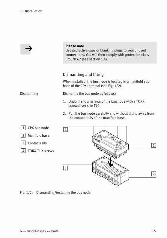
Please noteUse protective caps or blanking plugs to seal unusedconnections. You will then comply with protection classIP65/IP67 (see section 1.4).
Dismantling and fitting
When installed, the bus node is located in a manifold sub−base of the CPX terminal (see Fig.�1/2).
Dismantling Dismantle the bus node as follows:
1. Undo the four screws of the bus node with a TORXscrewdriver size T10.
2. Pull the bus node carefully and without tilting away fromthe contact rails of the manifold base.
1 CPX bus node
2 Manifold base
3 Contact rails
4 TORX T10 screws
3
4
1
2
Fig.�1/2: Dismantling/installing the bus node
1. Installation
1−6 Festo P.BE−CPX−FB38−EN en 0804NH
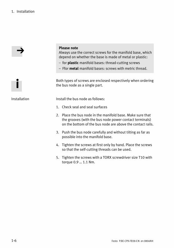
Please noteAlways use the correct screws for the manifold base, whichdepend on whether the base is made of metal or plastic:
� for plastic manifold bases: thread−cutting screws
� Ffor metal manifold bases: screws with metric thread.
Both types of screws are enclosed respectively when orderingthe bus node as a single part.
Installation Install the bus node as follows:
1. Check seal and seal surfaces
2. Place the bus node in the manifold base. Make sure thatthe grooves (with the bus node power contact terminals)on the bottom of the bus node are above the contact rails.
3. Push the bus node carefully and without tilting as far aspossible into the manifold base.
4. Tighten the screws at first only by hand. Place the screwsso that the self−cutting threads can be used.
5. Tighten the screws with a TORX screwdriver size T10 withtorque 0.9 � 1.1 Nm.

1. Installation
1−7Festo P.BE−CPX−FB38−EN en 0804NH
1.2 Settings of the DIL switches on the bus node
To set the CPX bus node, the cover for the DIL switches mustbe removed.
CautionThe CPX bus node contains electrostatically sensitivecomponents.
· Therefore, do not touch any contacts.
· Observe the handling specifications for electrostaticallysensitive components.
You avoid malfunctions of and damage to the electronics bydoing so.
1.2.1 Removing and fitting the cover over the DIL switches
You need a screwdriver in order to remove or fit the cover.
Please noteObserve the following instructions when removing orfitting the cover:
· Disconnect the power supply before removing the cover.
· Make sure that the seal is seated correctly when fittingthe cover.
· Tighten the two fastening screws at first by hand andthen with max. 0.4 Nm.

1. Installation
1−8 Festo P.BE−CPX−FB38−EN en 0804NH
1.2.2 Setting the DIL switches
You can set the following parameters with the DIL switchesunder the cover (see Fig.�1/3):
� bus node operating mode
� diagnostic mode.
Proceed as follows:
1. Switch off the power supply.
2. Remove the cover (see section 1.2.1).
3. Make the required settings (see Tab.�1/1 and Tab.�1/2).
4. Replace the cover (see section 1.2.1).
1 DIL switch 1: bus node operatingmode
2 DIL switch 2: for Remote I/Ooperating mode: Diagnostic mode
1 2
Fig.�1/3: Settings of the DIL switches on the bus node

1. Installation
1−9Festo P.BE−CPX−FB38−EN en 0804NH
Setting the operating mode with DIL switch 1
You can set the operating mode of the bus node with switch
element 1.1 of DIL switch 1 (see Tab.�1/1):
� Remote I/O operating mode
� Operating mode Remote Controller
Operating mode Setting DIL switch 1
Remote I/O operating mode
All functions of the CPX terminal are controlled directly by theEtherCAT−IO controller or a superordinate PLC.
The bus node thereby takes over the connection to theEtherCAT network.
DIL 1.1: OFFDIL 1.2: OFF(factory setting)
Operating mode Remote Controller
Requirement:a CPX−FEC is an integral part of the CPX terminal.
The FEC integrated in the terminal controls all functions.
The bus node thereby takes over the connection to theEtherCAT network.
DIL 1.1: ONDIL 1.2: OFF
Tab.�1/1: Setting the bus node operating mode with DIL switch 1

1. Installation
1−10 Festo P.BE−CPX−FB38−EN en 0804NH
Remote I/O � Explanation of the operating mode
All functions of the CPX terminal are controlled directly by theEtherCAT controller or a superordinate PLC:
� Control of the CPX valve terminal (also described asIO�Controller)
� Data exchange between controller and modules
� Parameterisation of the modules
� Diagnostics.
Controller and CPX valve terminal communicate via EtherCAT.The bus node thereby takes over the connection to theEtherCAT network and processing of the data exchange:
� Protocol implementation
� Forwarding of incoming and outgoing data.
EtherCAT protokol (in both operating modes)
The real−time−capable EtherCAT protocol is used for this.
An FEC integrated in the CPX terminal works as a passivemodule, i.e. without controller. In this case, the FEC can beused for connection to other networks, for example: The FECtakes over the forwarding of incoming and outgoing data andthus behaves like an I/O module.

1. Installation
1−11Festo P.BE−CPX−FB38−EN en 0804NH
Remote Controller � Explanation of the operating mode
A CPX−FEC integrated into the CPX terminal takes over controlof the terminal (also described as IO Controller), as the localcontroller of a larger system, for example.
Requirements for this operating mode:
� A CPX−FEC is an integral part of the CPX terminal.
� For its part, the FEC is in the Remote Controller operatingmode. Ensure that the bus node and FEC DIL switches areset according to the operating mode. If necessary, set�tings at the program level must also be adjusted, e.g. inthe program side hardware configuration.
The bus node also takes over the connection to EtherCATnetwork in this configuration:
� The FEC can communicate at the field bus level using an8−byte IO data field, e.g. with an EtherCAT controller.
� A superordinate controller can call up, e.g. status informa�tion of the valve terminal using this interface and match oroptimise the controller accordingly with other systemparts.
1. Installation
1−12 Festo P.BE−CPX−FB38−EN en 0804NH
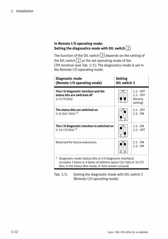
In Remote I/O operating mode:
Setting the diagnostics mode with DIL switch 2
The function of the DIL switch 2 depends on the setting of
the DIL switch 1 or the set operating mode of theCPX�terminal (see Tab.�1/1): The diagnostics mode is set inthe Remote I/O operating mode.
Diagnostic mode (Remote I/O operating mode)
SettingDIL switch 2
The I/O diagnostic interface and thestatus bits are switched off(+ 0 I/O bits)
2.1: OFF2.2: OFF(factorysetting)
The status bits are switched on(+ 8 (16) I bits) 1)
2.1: OFF2.2: ON
The I/O diagnostic interface is switched on(+ 16 I/O bits) 1)
2.1: ON2.2: OFF
Reserved for future extensions 2.1: ON2.2: ON
1 Diagnostic mode (status bits or I/O diagnostic interface)occupies 2 bytes or 4 bytes of address space (16 I bits or 16 I/Obits; in the Status Bits mode, 8�I bits remain unused)
Tab.�1/2: Setting the diagnostic mode with DIL switch 2(Remote I/O operating mode)

1. Installation
1−13Festo P.BE−CPX−FB38−EN en 0804NH
Please note(1) Use of the diagnostic mode (status bits or I/Odiagnostic interface) occupies 16 I or 16 I/O bits and thusreduces the number of I/O bits which are available formodule communication. In this way, the number ofaddressable modules is reduced in favour of additionalstatus or diagnostic information.
Take account of this fact for the planning of yourCPX�terminal.
(2) Subsequent activation requires a new configurationIn the subsequent activation of the diagnosis mode (statusbits or I/O diagnosis interface), the CPX−internal I/O imagecan be displaced.In this case, repeat the EtherCAT network configuration inyour configuration and programming software, e.g. Beck�hoff TwinCAT, in particular the assignment of inputs andoutputs.
In Remote Controller operating mode:
Function of the DIL switch 2
The function of the DIL switch 2 depends on the setting of
the DIL switch 1 or the set operating mode of theCPX�terminal (see Tab.�1/1):
In the Remote Controller operating mode, DIL switch 2 isreserved for future expansions.

1. Installation
1−14 Festo P.BE−CPX−FB38−EN en 0804NH
1.3 Connecting to the network
1.3.1 General information about EtherCAT networks
Please noteComponents with EtherCAT interfaces may be operatedonly in�networks where all connected network componentsare supplied with PELV power supplies or integrated powersupplies with similar protection.
Installation instructions
You can obtain specifications, installation notes and instruc�tions through the EtherCAT user organisation:
� EtherCAT Technology Group:http://www.ethercat.org/
� EtherCAT−specifications (�EtherCAT Specification",�Profiles"), guidelines (�Guidelines") and instructions(e.g. �How to Configure an EtherCAT Slave Device"):http://www.ethercat.org/en/publications.html
Observe the instructions there.

1. Installation
1−15Festo P.BE−CPX−FB38−EN en 0804NH
1.3.2 Overview of connections, network connectors and cables
Bus nodes Connections Network connectors Cable specification
CPX−FB38 2x M12 socket,D−coded, female,4−pin, according toIEC�61076−2−101,SPEEDCON®
compatible
Plug from Festo, typeNECU−M−S−D12G4−C2−ET,for Ethernet lines withcable diameters of6���8�mm
� Cable type:Shielded industrial Ethernet line(at least�category Cat 5)
� Cable length:max. 100�m between network par�ticipants (corresponding to spec�ifications for Ethernet networks,ISO/IEC�11801 and ANSI/TIA/EIA−568−B)
� Core cross section for max. linelength:22�AWG (for 100�m link length,based on ISO/IEC�11801)
Tab.�1/3: Overview of connections, network connectors and network cables
Please noteIf installation has not been carried out correctly and if highbaud rates are used, data transmission errors may occuras a result of signal reflections and attenuation.
Causes of transmission faults may be:
� incorrect screening/shield connection
� branches
� transmission over long distances
� unsuitable cables.
Observe the cable specification!
Refer to the manual of your controller for informationabout the required type of cable.

1. Installation
1−16 Festo P.BE−CPX−FB38−EN en 0804NH
1.3.3 Network interface
To connect to the network, there are two 4−pin M12 socketswith�D−coding on the�bus node�CPX−FB38 (for industrialEthernet use, corresponding to IEC�61076−2−101). The socketsare compatible with SPEEDCON® plugs.
Socket Pin Signal Explanation
M12, D−coded
1
2
3
4
1234Housing
TD+RD+TD�RD�FE
Transmission data (Transmit Data, TD) +Receive data (Receive Data, RD) +Send data �Receive data �Shield/functional earth(Shield/functional earth, FE)
Tab.�1/4: Pin assignment of the network interface
1.3.4 Network connection
Connection with plug from Festo
Connect the CPX terminal to the network with Festo plugstype NECU−M−S−D12G4−C2−ET. The plug is designed forEthernet lines with cable diameters of 6 � 8 mm.
To comply with protection class IP65/IP67:
� Use Festo plugs.
� Seal unused interfaces, see section 1.4.

1. Installation
1−17Festo P.BE−CPX−FB38−EN en 0804NH
M12 to RJ45 converter
For EtherCAT installations, it may be necessary to changebetween RJ45 and M12 connectors.
Application example: Connections between devices in theswitch cabinet with RJ45 connection and IP65/IP67 deviceswith M12 connection.
Adapter examples:
� Lumberg: 0981 ENC 100(RJ45/M12 adapter, M12 coupler, D−coded, mounting thread PG9, RJ45 coupling, 90 degrees)
� HARTING: eCon 6050 −BA
Cable specification
Use shielded industrial Ethernet round cable of categoryCat�5 or higher. You can find details regarding cable specifica�tion in Tab.�1/3.
The CPX bus node FB38 supports crossover detection:You can optionally use patch cables or crossover cables(Auto−MDI) for connecting your bus node to the network,controller or a PC.
Please noteIf the CPX terminal is fitted onto the moving part of amachine, the network cable on the moving part must beprovided with strain relief. Please also observe the relevantregulations in EN�60204 part 1.

1. Installation
1−18 Festo P.BE−CPX−FB38−EN en 0804NH
1.4 You will then comply with protection class IP65/IP67
In order to comply with protection class IP65/IP67, sealunused sockets with the appropriate plugs and covers.
Port Port IP65/IP67 Cover IP65/IP67 1)
L/A1, L/A2 (M12) Plug from Festo, type NECU−M−S−D12G4−C2−ET
Protective cap from Festo, type ISK−M12
Service interface (M12) Connecting cable and plug of thehandheld control unit (CPX−MMI)
Protective cap from Festo, type ISK−M12 2)
1) if connection is not used2) included in scope of delivery
Tab.�1/5: Connections and covers for protection class IP65/IP67

1. Installation
1−19Festo P.BE−CPX−FB38−EN en 0804NH
1.5 Pin assignment of power supply
Warning· Only use PELV circuits according to IEC/DIN EN 60204−1(Protective Extra−Low Voltage, PELV) for the powersupply. Take into account also the general requirements forPELV circuits as per IEC/DIN EN 60204−1.
· Use only power packswhich guarantee reliable electricalisolation of the operating voltage as per IEC/DINEN�60204−1.
Due to the use of PELV power units, protection against electricshock (protection against direct and indirect contact) is guar�anteed in accordance with IEC/DIN EN 60204−1 (electricalequipment of machines, general requirements).
The current consumption of a CPX terminal depends on thenumber and type of integrated modules and components.
Read the information about the power supply as well as onthe earthing measures to be carried out in the �CPX systemmanual (P.BE−CPX−SYS−...).

1. Installation
1−20 Festo P.BE−CPX−FB38−EN en 0804NH
System supply, additionalsupply and valve supply
The CPX terminal is supplied with operating and load powervia the manifold base with system, additional and valvesupply.
Plugs Pin assignment of manifold base with
System supplytype CPX−GE−EV−S...type CPX−M−GE−EV−S...
Additional powersupplytype CPX−GE−EV−Z...type CPX−M−GE−EV−Z...
Valve supply moduletype CPX−GE−EV−V...
7/8"−5POL
1
2
3
4
5
1: 0 VVAL / 0 VOUT2: 0 VEL/SEN3: Earth connection
(incoming)4: 24 VEL/SEN5: 24 VVAL / 24 VOUT
1: 0 VOUT2: not connected3: Earth connection
(incoming)4: not connected5: 24 VOUT
�
DC
B A
7/8"−4POL 1)
A: 24 VEL/SENB: 24 VVAL / 24 VOUTC: Earth connectionD: 0 VEL/SEN /
0 VVAL / 0 VOUT(incoming)
A: not connectedB: 24 VOUTC: Earth connectionD: 0 VOUT (incoming)
A: not connectedB: 24 VVALC: Earth connectionD: 0 VVAL (incoming)
2
3
4
1
M18
1: 24 VEL/SEN2: 24 VVAL / 24 VOUT3: 0 VEL/SEN /
0 VVAL / 0 VOUT4: Earth connection
1: not connected2: 24 VOUT3: 0 VOUT4: Earth connection
1: not connected2: 24 VVAL3: 0 VVAL4: Earth connection
1) Note the specifications on the plugVEL/SEN: Operating voltage for electronics/sensorsVOUT: Load voltage for outputsVVAL: Load voltage for valves
Tab.�1/6: Pin assignment for system supply, additional supply and valve supply

Commissioning
2−1Festo P.BE−CPX−FB38−EN en 0804NH
Chapter 2

2. Commissioning
2−2 Festo P.BE−CPX−FB38−EN en 0804NH
Contents
2. Commissioning 2−1 . . . . . . . . . . . . . . . . . . . . . . . . . . . . . . . . . . . . . . . . . . . . . . . .
2.1 General information 2−3 . . . . . . . . . . . . . . . . . . . . . . . . . . . . . . . . . . . . . . . . . . . . .
2.2 Address assignment 2−4 . . . . . . . . . . . . . . . . . . . . . . . . . . . . . . . . . . . . . . . . . . . . .
2.3 Addressing 2−13 . . . . . . . . . . . . . . . . . . . . . . . . . . . . . . . . . . . . . . . . . . . . . . . . . . . .
2.3.1 Basic rules for addressing 2−13 . . . . . . . . . . . . . . . . . . . . . . . . . . . . . . . .
2.3.2 Address assignment after extension or conversion 2−19 . . . . . . . . . . . .
2.4 Configuration 2−21 . . . . . . . . . . . . . . . . . . . . . . . . . . . . . . . . . . . . . . . . . . . . . . . . . .
2.4.1 Registering slave properties (�XML file") in the configuration program 2−21 . . . . . . . . . . . . . . . . . . . . . . . . . . . . . .
2.4.2 Addressing and data access (data objects) 2−28 . . . . . . . . . . . . . . . . . . .
2.4.3 CPX terminal configuration using Beckhoff TwinCAT (EtherCAT�network configuration) 2−29 . . . . . . . . . . . . . . . . . . . . . . . . . .
2.4.4 Linking automation project (PLC project) 2−38 . . . . . . . . . . . . . . . . . . . . .
2.4.5 EtherCAT topology representation 2−40 . . . . . . . . . . . . . . . . . . . . . . . . . .
2.4.6 Configuration in the Remote Controller operating mode 2−42 . . . . . . . .
2.5 Parameterisation 2−43 . . . . . . . . . . . . . . . . . . . . . . . . . . . . . . . . . . . . . . . . . . . . . . .
2.5.1 Introduction to parameterisation 2−43 . . . . . . . . . . . . . . . . . . . . . . . . . . .
2.5.2 General prerequisite for parameterisation 2−45 . . . . . . . . . . . . . . . . . . .
2.5.3 Methods of parameterisation 2−46 . . . . . . . . . . . . . . . . . . . . . . . . . . . . . .
2.5.4 Parameterisation via the Festo Maintenance Tool (method 1) 2−47 . . . .
2.5.5 Parameterisation with the handheld unit (method 2) 2−47 . . . . . . . . . . .
2.6 Remarks on parameters of the CPX system settings 2−49 . . . . . . . . . . . . . . . . . . .
2.6.1 Parameterisation of the Fail safe mode 2−49 . . . . . . . . . . . . . . . . . . . . . .
2.6.2 CPX−FB38−specific process of start parameterisation during switching on (system start) 2−51 . . . . . . . . . . . . . . . . . . . . . . . . . .
2.7 Application example for the parameterisation 2−53 . . . . . . . . . . . . . . . . . . . . . . . .
2.8 Checklist for starting up the CPX terminal 2−54 . . . . . . . . . . . . . . . . . . . . . . . . . . .
2.9 Bus node replacement 2−56 . . . . . . . . . . . . . . . . . . . . . . . . . . . . . . . . . . . . . . . . . . .

2. Commissioning
2−3Festo P.BE−CPX−FB38−EN en 0804NH
2.1 General information
Switching on the power supply
Please notePlease observe the switching−on instructions in the manualof your control system (PLC/IPC).
Separate�supply If the control system and the field bus slaves have separatepower supplies, the devices must be switched on in thefollowing sequence:
1. Switch on the operating voltage supply of all bussubscribers (I/O Devices).
2. Switch on the operating voltage supply for the controller.
Addressing, configuration and parameterisation
Addressing The address space of a CPX terminal in the EtherCAT networkis limited. Before starting up or configuring the CPX terminal,determine the number of assigned inputs and outputs.
Configuration Configuration of a CPX terminal and the related CPX bus nodedepends on the control system used. The basic procedureand the required configuration data are presented in thefollowing pages.
Parameterisation A CPX terminal in the EtherCAT network can be parameterisedonly with a handheld control unit (CPX−MMI) or the FestoMaintenance Tool (CPX−FMT) (no parameterization throughthe control system).

2. Commissioning
2−4 Festo P.BE−CPX−FB38−EN en 0804NH
2.2 Address assignment
Please noteThe address space of a CPX terminal in the EtherCATnetwork is limited.
The CPX bus node for EtherCAT provides the CPX terminalwith an address space of up to 64 bytes for inputs (I) and64�bytes for outputs (O).
Each module of the CPX terminal occupies a certainnumber of I/O bits, bytes or words in the context ofmodule communication.
Please refer to Tab.�2/1 to Tab.�2/6 for the number of I/Obytes occupied (of the respective module).
Also, certain functions, e.g. the I/O diagnostics interface(STI), reduce the�number of available I/O bytes (in favourof status or diagnostics functions).
Take account of this fact for the planning of yourCPX�terminal.
Before starting up or configuring the CPX terminal, determinethe number of assigned inputs and outputs. Tab.�2/7 pro�vides help with this.
Use the configuration documents, the handheld control unit(CPX−MMI) or the Festo Maintenance Tool (CPX−FMT) todetermine address assignment or terminal set−up.
In the handheld control unit, the individual modules of theCPX terminal are displayed with the respective module ident�ifiers. Using the module identifier and the following tables,you can determine the module type and, with it, the numberof inputs and outputs occupied by the module.

2. Commissioning
2−5Festo P.BE−CPX−FB38−EN en 0804NH
Module identifiers Each module, including the bus node, has its own identifier,the so−called module identifier. It serves to determine andlocalise the module type, for example as part of configur�ation. Apply the�module identifiers � from left to right corresponding to the physical order as installed in theCPX�terminal � in your configuration program (e.g. BeckhoffTwinCAT, see section 2.4).
In graphically oriented configuration programs, the moduleidentifiers are typically found in a separate listing of allavailable hardware modules or field devices, e.g. in a moduledirectory or module catalogue.
Electric modules
Tab.�2/1 and Tab.�2/2 give an overview of the assignedaddress spaces of different electrical modules and of the busnode in the Remote I/O�operating mode.
Tab.�2/3 shows the assigned address space of the bus nodein the Remote Controller operating mode.
The address assignment within the individual CPXI/O�modules can be found in the manual for the I/O module(P.BE−CPX−EA−...).
Details on the CP interface can be found in the manual for theCP interface (P.BE−CPX−CP−...).

2. Commissioning
2−6 Festo P.BE−CPX−FB38−EN en 0804NH
Electric modules Module type Moduleid tifi 1)
Assigned address space
Description identifier 1) Inputs Outputs
Bus node for EtherCAT in operating mode Remote I/O 2)
without diagnostics access
CPX−FB38 FB38−RIO... � �
Bus node for EtherCAT in operating mode Remote I/O 2)
with status bits [Status]
CPX−FB38 FB38−RIO... 2 bytes/8 (16) I 3) (8 bits used)
�
Bus node for EtherCAT in operating mode Remote I/O 2)
with I/O diagnostic interface[System Table Interface, STI]
CPX−FB38 FB38−RIO... 2 bytes/16 I 2 bytes/16 O
Digital 4−input module CPX−4DE 4DI 1 byte/4 (8) I 3)
�
Digital 8−input module CPX−8DE 8DI 1 byte/8 I �
Digital 8−input module with channel diagnosis
CPX−8DE−D 8DI−D 1 byte/8 I �
Digital 8−input module,n−switching
CPX−8NDE 8NDI 1 byte/8 I �
Digital 16−input module CPX−16DE 16DI 2 bytes/16 I �
Digital 16−input module with channel diagnosis
CPX−M−16DE−D 16DI−D 2 bytes/16 I �
Digital 4−output module CPX−4DA 4DO � 1 byte/4 (8) O 3)
Digital 8−output module CPX−8DA 8DO � 1 byte/8 O
Digital 8−output high currentoutput�module
CPX−8DA−H 8DO−H � 1 byte/8 O
1) Module identifier in the handheld unit or in the hardware config. of the programming software.2) Number of occupied I/O bytes in the Remote Controller operating mode: see Tab.�2/33) Diagnostic mode status bits assigned 8 I or 2 bytes of address space (8 I or 8 bits remain unused);
4−way modules CPX−4DE and CPX−4DA always occupy 8 I or 8 O or 1 byte of address space (4 I/O or 8 bits of address space remain unused)
Tab.�2/1: Address assignment of electric CPX modules (overview; bus node in Remote I/O operating mode) � part 1

2. Commissioning
2−7Festo P.BE−CPX−FB38−EN en 0804NH
Electric modules Modulet
Moduleid tifi 1)
Assigned address space
Description type identifier 1) Inputs Iutputs
Digital multi I/O module CPX−8DE−8DA 8DI/8DO 1 bytes/8 I 1 bytes/8 O
Analogue 2−input module CPX−2AE−U−I 2AI 2 words/32 I �
Analogue 4−input module CPX−4AE−I 4AI−I 4 words/64 I �
Analogue 4−input module(Temp. module for RTD sensors)
CPX−4AE−T 4AI−T 2 words or 4 words/ 32/64 I�4)
�
Analogue 4−way input module(Temp. module for TC�sensors)
CPX−4AE−TC 4AI−TC 4 words/64 I �
Analogue 2−output module CPX−2AA−U−I 2AO � 2 words/32 O
CP interface CPX−CP−4−FB CPI max. 8�words/128 I 5)
max. 8�words/128 O 5)
1) Module identifier in the handheld unit or in the hardware configuration of the programming software.
4) Number of inputs which can be switched between 2 and 4.5) Address space assignment depends on the string assignment.
Tab.�2/2: Address assignment of electric CPX modules (overview; bus node in Remote I/O operating mode) � part 2

2. Commissioning
2−8 Festo P.BE−CPX−FB38−EN en 0804NH
Configuration of the bus node
The identification of the bus node and the diagnostics modeare configured in the Remote I/O operating mode(see�Tab.�2/1).
In the Remote Controller operating mode only the identifierof the bus node will be configured (see Tab.�2/3):
Electric modules Moduletype
Moduleidentifier 1)
Assigned address space
Description Inputs Outputs
Bus node for EtherCATIn Remote Controller operating mode
CPX−FB38 FB38−RC 8 bytes/64 I 8 bytes/64 O
1) Module identifier in the handheld unit or in the hardware configuration of the programming software.
Tab.�2/3: Address assignment of the bus node in the Remote Controller operating mode

2. Commissioning
2−9Festo P.BE−CPX−FB38−EN en 0804NH
Pneumatic interfaces and pneumatic modules
Tab.�2/5 and Tab.�2/6 give an overview of the assigned ad�dress spaces of different pneumatic interfaces and modules.
Configuration of thepneumatics (valves)
The valves are configured according to the pneumaticinterface used:
� Valves of type 03 (Midi/Maxi), type 12 (CPA) andtype�44/45 (VTSA/VTSA−F or ISO):
When extensions are added to the valve side, only oneconfiguration is required for the pneumatic interface. Inthe pneumatic interface, the number of valve coils is setusing a DIL switch.
� Valves of type 32 and 33 (MPA, MPA−F and MPA−P orVPPM pneumatic modules):
From the technical point of view, the individual MPApneumatic modules each represent an electric module forcontrolling the attached valves.
A configuration is required for each pneumatic module oftype MPA:
� pneumatic modules of type MPA1 each occupy 1 byte of address space or 8 outputs regardless of how many valves are attached to the pneumatic module.
� pneumatic modules of type MPA2 each occupy 1 byte of address space or 8 outputs, but only 4 bits are used.
� pneumatic modules of type MPA−P occupy 1 byte of address space or 16 inputs.
� pneumatic modules of type VPPM occupy 2 bytes of address space or 1 byte I/O or 16 inputs and 16 outputs.
Pneumatic modules of type MPA−P and VPPM are analoguemodules. Note the order of the modules in addressing or I/Omapping (see Tab.�2/8).
Further information about the pneumatics can be found in thecorresponding pneum. descriptions (see document overview,manuals for the CPX terminal in the CPX system manualCPX−P.BE−CPX−SYS−...).

2. Commissioning
2−10 Festo P.BE−CPX−FB38−EN en 0804NH
The manuals for the pneumatic valve cluster (Midi/Maxi, CPA,MPA and VTSA/VTSA−F or ISO) contain the address assign�ment within the pneumatic modules.
For further inform. on MPA pneum. modules and�the�pneum. in�terfaces: see manual for the CPX I/O modules (P.BE−CPX−EA−...).
CPX pneumatic interfaces forMPA and related modules
Module type Moduleidentifier 1)
Assignedaddress space
Inputs Outputs
Pneumatic interface for MPA or MPA−F valves (type 32/33)
VMPA−FB−EPL−... � � �
MPA1 pneumatic module (type 32/33)without electrical isolation
VMPA1−FB−EMS−8 2)
(CPX type 32/33: 1−8V...)MPA1S � 1 byte/
8 O
MPA1 pneumatic module (type 32/33)with electrical isolation
VMPA1−FB−EMG−8 2)
(CPX type 32/33−G: 1−8V...)MPA1G � 1 byte/
8 O
MPA2 pneumatic module (type 32/33)without electrical isolation
VMPA2−FB−EMS−4 2)
(CPX type 32/33: 1−4V...)MPA2S � 1 byte/
4 (8) O 3)
MPA2 pneumatic module (type 32/33)with electrical isolation
VMPA2−FB−EMG−4 2)
(CPX type 32/33−G: 1−4V...)MPA2G � 1 byte/
4 (8) O 3)
MPA1 pneumatic module (type 32/33)without electrical isolation, with diagnostic function D2
VMPA1−FB−EMS−D2−8 2)
(CPX type 32/33: 1−8V...)MPA1S−D � 1 byte/
8 O
MPA1 pneumatic module (type 32/33)with electrical isolation, with diagnostic function D2
VMPA1−FB−EMG−D2−8 2)
(CPX type 32/33−G: 1−8V...)MPA1G−D � 1 byte/
8 O
MPA2 pneumatic module (type 32/33)without electrical isolation, with diagnostic function D2
VMPA2−FB−EMS−D2−4 2)
(CPX type 32/33: 1−4V...)MPA2S−D � 1 byte/
4 (8) O 3)
MPA2 pneumatic module (type 32/33)with electrical isolation, with diagnostic function D2
VMPA2−FB−EMG−D2−4 2)
(CPX type 32/33−G: 1−4V...)MPA2G−D � 1 byte/
4 (8) O 3)
1) Module identifier in the handheld unit or in the hardware config. of the programming software2) Type of electronic module used3) 4−way modules MPA2 always occupy 8 I (1 byte) of address space (4 I or 8 bits remain unused)
Tab.�2/4: Overview of CPX pneumatic interfaces and pneumatic modules (part 1)

2. Commissioning
2−11Festo P.BE−CPX−FB38−EN en 0804NH
CPX pneumatic interfaces forMPA d l t d d l
Module type Moduleid tifi 1)
Assignd addr. spaceMPA and related modules identifier 1) Inputs Outputs
VPPM proportional pressure−regulating valve (type 32)
VPPM−6TA−L−1−F−... VPPM 1 word/16 I
1 word/16 O
MPA−P pressure sensor module VMPA−FB−PS−... MPA−P 1 word/16 I �
1) Module identifier in the handheld unit or in the hardware config. of the programming software
Tab.�2/5: Overview of CPX pneumatic interfaces and pneumatic modules (part 2)
Pneumatic interfaces forMidi/M i CPA VTSA (ISO)
Module type Moduleid tifi 1)
Assignd addr. spaceMidi/Maxi, CPA, VTSA (ISO) identifier 1) Inputs Outputs
Pneumatic interface for Midi/Maxivalves (type 03) with setting�2)
� 1 � 8 valve coils� 1 � 16 valve coils� 1 � 24 valve coils� 1 � 32 valve coils (26 can be used)
CPX−GP−03−4.0(CPX type 03: 1−...−...)
TYPE3 �
1 byte/8 O2 bytes/16 O3 bytes/24 O4 bytes/32 O
Pneumatic interface for CPA valves(type 12) with setting 2)
� 1 � 8 valve coils� 1 � 16 valve coils� 1 � 24 valve coils (22 can be used)
CPX−GP−CPA−10CPX−GP−CPA−14(CPX type 12: 1−...−...)
CPA10/14 �
1 byte/8 O2 bytes/16 O3 bytes/24 O
Pneumatic interface for VTSA or VTSA−F pneumatic (ISO, type 44/45)with adjustment 2)
� 1 � 8 valve coils� 1 � 16 valve coils� 1 � 24 valve coils� 1 � 32 valve coils
VABA−10S6−x1(CPX type44/45: 1−...−...)
ISO PlugIn ortype�44 ortype�45 3)
�
1 byte/8 O2 bytes/16 O3 bytes/24 O4 bytes/32 O
1) Module identifier in the handheld unit or in the hardware config. of the programming software2) Setting with DIL switch in the pneumatic interface3) Display text (module identifier) dependent on the version of the handheld unit
Tab.�2/6: Overview of CPX pneumatic interfaces and pneumatic modules (part 3)

2. Commissioning
2−12 Festo P.BE−CPX−FB38−EN en 0804NH
Calculating the number of inputs/outputs
Use Tab.�2/7 to calculate the number of inputs and outputs(of address assignment) of your CPX terminal.
Input/output modules and system diagnosis Inputs Outputs
1. Status bits or I/O diagnostic interface 1) + _____ I + _____ O
2. Number of input modules CPX−4DE + __ x 8 I 2) + _____ I
3. Number of input modules CPX−8DE, 8DE−D,−8NDE + __ x 8 I + _____ I
4. Number of input modules CPX−16DE, 16DE−D + __ x 16 I + _____ I
5. Number of output modules CPX−4DA + __ x 8 O 2) + _____ O
6. Number of output modules CPX−8DA, 8DA−H + __ x 8 O + _____ O
7. Nnumber of multi−I/O modules CPX−8DE−8DA + __ x 8 IO + _____ I + _____ O
8. Number of analogue input modules CPX−2AE−U−I + __ x 32 I + _____ I
9. Number of analogue input modules CPX−4AE−I + __ x 64 I + _____ I
10.Number of analogue input modules CPX−4AE−T + __ x 32 I/ x 64 I + _____ I
11.Number of analogue input modules CPX−4AE−TC + __ x 64 I + _____ I
12.Number of analogue output modules CPX−2AA−U−I + __ x 32 O + _____ O
13.Number of inputs and outputs of other modules + __ IO(e.g. CP interface, VPPM−/MPA−P pneumatic module)
+ _____ I + _____ O
14.Midi/Maxi, CPA and VTSA/VTSA−F pneumatic interface:Number of configured valve magnet coils (+ 8 � 32 O; 32 O (Midi/Maxi, VTSA/VTSA−F) or 24 O (CPA) are configured at the factory)
+ _____ O
15.Number of MPA1 or MPA2 pneumatic modules + __ x 8 O 2) + _____ O
16.Total sum of inputs/outputs to be configuredTotal from 1. to 15. = _____ I = _____ O
1) Number of occupied inputs /outputs: see Tab.�1/22) 4−way modules CPX−4DE and CPX−4DA as well as MPA modules (MPA2 and VPPM) always occupy
8 inputs or outputs (1 byte; available address space remains partially unused)
Tab.�2/7: Identifying the assigned address space (total of inputs and outputs)

2. Commissioning
2−13Festo P.BE−CPX−FB38−EN en 0804NH
2.3 Addressing
2.3.1 Basic rules for addressing
� The field bus node counts as a module with 0�inputs and0�outputs when the status bits and the I/O diagnosticinterface are deactivated.
� Note the remarks regarding address assignment insection 2.2.
� The address assignment of the inputs does not dependon the address assignment of the outputs.
� Counting is from left to right, addressing in bytes:Modules with less than 8 bits occupy 8 bits of addressspace, but do not use all this space.
� The I/Os of different module types are assignedseparately from each other. Observe the sequence ofaddressing: see Tab.�2/8.
Please noteIf necessary, status bits or an I/O diagnostic interface canbe activated by DIL switch (see Tab.�1/2):
� If the 8 status bits are activated, they will occupy thefirst 16 inputs in the address range (8 used).
� If the I/O diagnostic interface is activated, it will occupythe first 16 inputs and outputs in the address range.

2. Commissioning
2−14 Festo P.BE−CPX−FB38−EN en 0804NH
Sequence of addressing Description
1. Status bits or I/Odiagnostic interface 1)
Delivers status and diagnostic information; activate through DILswitches; occupies the first 16 inputs or inputs and outputs 2)
2. Analogue modules Modules with analogue inputs/outputs
3. Technology modules e.g. CP interface, front end controller (CPX−FEC)
4. Digital modules Modules with digital inputs/outputs
1) See also note above as well as Tab.�1/2 and Tab.�2/1.2) Depending on the setting, you can also occupy this address space with modules
(see also following information).
Tab.�2/8: Sequence of addressing
If the status bits or I/O diagnostic interface are activatedlater, that is, after the initial start−up, the moduleconfiguration for the first 16 inputs or 16 inputs and outputsmust be adjusted.
Move the modules originally configured in this addressspace into another area. Configuration of these modulesmust be repeated, if necessary (see also section 2.4regarding configuration with EtherCAT configuration andprogram software, e.g. Beckhoff TwinCAT).
Configuration examples
Example 1: CPX terminal with MPA1 and MPA2 pneumatic
Fig.�2/1 shows as an example a CPX terminal with MPApneumatics and the following setting:
� Status bits and I/O diagnostic interface deactivated
The address assignment for this example terminal(in�Fig.�2/1) is shown in Tab.�2/9.

2. Commissioning
2−15Festo P.BE−CPX−FB38−EN en 0804NH
Module no.: 0
1 2
8DI 4DO 8DI
8A
3
8DO
8A
1 2 3 4 5 6
4A 4A
4
1 Bus node CPX−FB38
2 MPA pneumatic interface
3 MPA1 pneumatic modules (8 O each)
4 MPA2 pneumatic modules (4 O each)
Fig.�2/1: Example terminal 1 (with MPA1 and MPA2 pneumatics)
Moduleno.
Module Input address Output address
0 Bus node CPX−FB38 � �
1 Digital 8−input module CPX−8DE I0 � I7 �
2 Digital 4−output module CPX−4DA � O0 � O7 *)
3 MPA1 pneumatic module (8 O) � O8 � O15
4 MPA1 pneumatic module (8 O) � O16 � O23
5 MPA2 pneumatic module (4 O) � O24 � O31 *)
6 MPA2 pneumatic module (4 O) � O32 � O39 *)
*) 8 bits (1 byte) assigned, 4 bits used � when the Festo XML file is used, the addresses are occupied bytewise (refers to module no. 2, 5 and 6)
Tab.�2/9: Addressing the example terminal 1 (see Fig.�2/1)

2. Commissioning
2−16 Festo P.BE−CPX−FB38−EN en 0804NH
Example 2: CPX terminal with CP interface
Fig.�2/2 shows as an example a CPX terminal withCP�interface and the following setting:
� Status bits and I/O diagnostic interface deactivated
The address assignment for this example terminal(in�Fig.�2/2) is shown in Tab.�2/10.
1 2 3 4 5 6Module no.: 0
8 O 8 O
1
2
3
4
5
6
8DI 4DO 8DI 8DO
1 Bus node CPX−FB38
2 CPV valve terminal (16 O) on the CP interface (string�1)
3 CP input module (16DI)
4 Sensor
5 Cylinders
6 CP output module (16DO) on the CP interface (string 4)
Fig.�2/2: Example terminal 2 (with CP interface)

2. Commissioning
2−17Festo P.BE−CPX−FB38−EN en 0804NH
Moduleno.
Module Input address Output address
0 Bus node CPX−FB38 � �
1 Digital 8−input module CPX−8DE I32 � I39 �
2 Digital 4−output module CPX−4DA � O128 � O135 *)
3 CP interface CPX−CP... (In this case: 4 bytes I, 16 bytes O)
I0 � I32 O0 � O127
4 Digital multi−I/O module CPX−8DE−8DA I40 � I47 O136 � O143
5 MPA1 pneumatic module (8 O) � O144 � O151
6 MPA1 pneumatic module (8 O) � O152 � O159
*) 8 bits occupied, 4 bits used
Tab.�2/10: Addressing the example terminal 2 (see Fig.�2/2)
Example 3: CPX terminal with analogue module and VTSA�pneumatics
Fig.�2/3 shows as an example a CPX terminal with analoguemodule and VSTA pneumatics as well as the following setting:
� Status bits activated
� VTSA pneumatic interface set to 1 � 8 valve coils (8 O)
The address assignment for this example terminal(in�Fig.�2/3) is shown in Tab.�2/11.

2. Commissioning
2−18 Festo P.BE−CPX−FB38−EN en 0804NH
1 2
8DI 8DI 4DO 8DI 2AO
3
8DO
8 O
Module no.: 0 1 2 3 4 5 6
1 Bus node CPX−FB38 (with status bits)
2 VTSA pneumatic interface (set to 1 � 8 valve coils)
3 VTSA pneumatics (type 44)
Fig.�2/3: Example terminal 3 (with analogue module and VTSA pneumatics)
Moduleno.
Module Input address Output address
0 Bus node CPX−FB38 (with status bits) I0 � I15 1) �
1 Digital 8−input module CPX−8DE I16 � I23 �
2 Digital 8−input module CPX−8DE I24 � I31 �
3 Digital 4−output module CPX−4DA � O32 � O39 2)
4 Digital multi−I/O module CPX−8DE−8DA I32 � I39 O40 � O47
5 Analogue 2−output module CPX−2AA � O0 � O31
6 VTSA pneumatic interface set to 1���8 valve coils � O48 � O55
1) 16 bits assigned, 8 bits used2) 8 bits assigned, 4 bits used
Tab.�2/11: Addressing the example terminal 3 (see Fig.�2/3)

2. Commissioning
2−19Festo P.BE−CPX−FB38−EN en 0804NH
2.3.2 Address assignment after extension or conversion
A speciality of the CPX terminal is its flexibility. If the demandsplaced on the machine change, the equipment fitted on theCPX terminal can also be modified.
CautionIf the CPX terminal is extended or converted at a laterstage, the input/output addresses may be shifted. This applies in the following cases:
� if additional modules are inserted between existingmodules
� if existing modules are removed or replaced by othermodules which have more or fewer input/outputaddresses
� if manifold sub−bases (CPA) or pneumatic sub−bases(Midi/Maxi) for single−solenoid valves are replaced bymanifold bases for double−solenoid valves or vice versa(see pneumatics manual)
� if additional manifold sub−bases (CPA) or sub−bases(Midi/Maxi) are inserted between existing sub−bases
� the diagnostic mode (status bits or the I/O diagnosticinterface) is activated/deactivated.
Example terminal 3 modified
The next diagram shows with terminal 3 as an example(Fig.�2/4) the effects of modifications to the addressassignment (compare with Fig.�2/3).
The following has been changed:
� The status bits have been deactivated.
� In the case of module no. 1 an 8−input module has beenreplaced by a 16−input module.
� The pneumatic interface has been set to 16 outputs(16�O) in order to reserve addresses for an extension tothe pneumatics.

2. Commissioning
2−20 Festo P.BE−CPX−FB38−EN en 0804NH
1 2
16DI 8DI 4DO 8DI 2AO
3
8DO
16 O
Module no.: 0 1 2 3 4 5 6
1 Modified: Status bits deactivated
2 Modified: 8DI module replaced by 16DI module
3 Modified: Pneumatic interface (now set with DIL switch to 1���16�valve coils)
Fig.�2/4: Example terminal 3 after extension/conversion (compare with Fig.�2/3)
Moduleno.
Module Input address Output address
0 Field bus node CPX−FB38 with deactivated status bits
Depends on DIL switch settings (see Tab.�1/2)
1 Digital 16−input module CPX−16DE I0 � I15 �
2 Digital 8−input module CPX−8DE I16 � I23 �
3 Digital 4−output module CPX−4DA � O32 � O39 1)
4 Digital multi−I/O module CPX−8DE−8DA I24 � I31 O40 � O47
5 Analogue 2−output module CPX−2AA � O0 � O31
6 VTSA pneumatic interface withDIL�switch set to 1���16 valve coils
� O48 � O63
bold = changed module or changed setting1) 8 bits occupied, 4 bits used
Tab.�2/12: Addressing the example terminal 3 after extension/conversion (see Fig.�2/4)

2. Commissioning
2−21Festo P.BE−CPX−FB38−EN en 0804NH
2.4 Configuration
General instructions on commissioning
Configuration of the CPX terminal demands a very accurateprocedure, as different configuration specifications are sometimes necessary for each slave, i.e. for each device and each�Box" on the EtherCAT network, due to the modularstructure.
Note here the specifications in the sections which follow(as�from section 2.4.1 regarding the configuration, andin�section 2.3 as well as 2.4.2 regarding the addressing).
2.4.1 Registering slave properties (�XML file") in the configurationprogram
When you commission a new EtherCAT slave, i.e. an EtherCATdevice the first time, you must inform your configuration andprogramming software about certain properties of the slave.
The properties of the various slaves are usually administeredby the configuration program in a configuration file, i.e. theEtherCAT Device Description File (in Beckhoff TwinCATreferred to as System Manager Tree Item Description).
Device Description File(�XML file")
This file or their corresponding contents have been madeavailable using the �Extensible Markup Language" (XML).Therefore, the EtherCAT Device Description File is commonlyknown as �XML file".
The XML file is used to identify the bus node in the EtherCATnetwork. Using the XML file, basic properties of the EtherCATdevice as well as information concerning the manufacturerare provided to the configuration program.
2. Commissioning
2−22 Festo P.BE−CPX−FB38−EN en 0804NH
Source (download link)
You will find the most recent EtherCAT configuration file(XML file) for CPX terminals and bus node CPX−FB38 on theFesto website at:
� www.festo.com/fieldbus
Inserting the XML file · To extend the XML library of your configuration program,insert the bus node−specific XML file into the programdirectory of the configuration program, in BeckhoffTwinCAT in:
C:\programs\TwinCAT\Io\EtherCAT
Importing the XML file · Afterwards, import the XML file into your configurationprogram, in the Beckhoff TwinCAT System Manager in:
�Actions" > �Import XML Descriptions..."
NoteYou will find a detailed description of the XML file import inthe subsequent section �XML file import � detailedinformation".

2. Commissioning
2−23Festo P.BE−CPX−FB38−EN en 0804NH
Slave properties
In the framework of importing the XML file, subsequent in�formation about the bus node or the EtherCAT slave is pro�vided to the configuration program.
Information Description
Vendor Name Festo AG & Co. KG
Vendor ID 0000001Dh
Product Code 00000026h
Version Number 00000002h
EtherCAT−Input/Output−Size 64 Byte/64 Byte (independent of the operating mode)
Product Name CPX−FB38 (CPX−FB38 EtherCAT Bus module)
Catalog Number 552 046
Tab.�2/13: EtherCAT slave properties
When the XML file has been imported, i.e. after incorporationof the device properties into the configuration program, thebus node is registered as potential EtherCAT device. Hence,you can integrate the bus node into your EtherCAT network,and configure the CPX terminal.

2. Commissioning
2−24 Festo P.BE−CPX−FB38−EN en 0804NH
XML file import � detailed information
You require an EtherCAT configuration file, i.e. the �XML file",to configure and programme the CPX terminal with a PC or acorresponding software package, e.g. Beckhoff TwinCAT. The XML file contains all the required information to configureand adjust (set up) the CPX terminal using configuration andprogramming software, e.g. TwinCAT.
You will find explanations regarding the XML file insection�2.4.1.
Source (download link)
You will find the most recent EtherCAT configuration file(XML file) for CPX terminals and bus node CPX−FB38 on theFesto website at:
� www.festo.com/fieldbus
File type File name Language Description
XML Festo CPX−FB38.xml(check the link men�tioned above for thelatest version of theXML file)
Language−independent
�EtherCAT Device Description File" for Beckhoff TwinCAT or compatible configuration and programming software (�Beckhoff TwinCAT System Manager Tree ItemDescription")
Tab.�2/14: EtherCAT configuration file (�XML file") for CPX terminals and bus node CPX−FB38
Download · Download the current XML file onto your PLC system.
NoteCheck the above mentioned link casually regarding mostrecent version of the XML file.

2. Commissioning
2−25Festo P.BE−CPX−FB38−EN en 0804NH
· Copy the bus node−specific XML file into the programdirectory of your configuration program � in BeckhoffTwinCAT in:
� C:\programs\TwinCAT\Io\EtherCAT
To ensure that TwinCAT uploads the configuration file, thesubseqeuntly desribed import of the XML file is required(see also Fig.�2/5).
Import 1. Start the configuration program of your PLC, e.g. theBeckhoff TwinCAT System Manager (�1 in Fig.�2/5).
2. Import (incorporate) the XML file into the configurationprogram � in TwinCAT by using:
� �Actions" > �Import XML Descriptions..." (�2 in Fig.�2/5)
A file selection Pop−up window 3 opens (is displayed).
3. Select the Festo XML file 4, and click �Open" 5 toconfirm and cause the selection.
Having completed the import of the XML file, i.e. afterincorporation of the device properties into the configurationprogram, the bus node is registered as potential EtherCATdevice. Hence, you can integrate the bus node into yourEtherCAT network, and configure the CPX terminal(see�section 2.4.3).
Symbolic representationof�the CPX terminal
The Festo XML file comprises a symbolic representation ofthe bus node and the corresponding CPX terminal which isreflected in the EtherCAT topology display, for instance(see�section 2.4.5). The topology display however is firstavailable after completion of the EtherCAT networkconfiguration. (The network configuration is described insection 2.4.3.)

2. Commissioning
2−26 Festo P.BE−CPX−FB38−EN en 0804NH
1 2 3 4 5
Fig.�2/5: Registering slave properties in the configuration program (importing XML file)

2. Commissioning
2−27Festo P.BE−CPX−FB38−EN en 0804NH
2.4.2 Addressing and data access (data objects)
Addressing
Addressing the individual modules requires the supervisorycontroller: The EtherCAT master determines the position ofthe EtherCAT devices within the network. Thereby, block−oriented addressing is applied (in contrast to block−orientedaddressing of other field bus systems).
The controller uses the following for local addressing:
� the physical position of the devices within the EtherCATnetwork (Auto Increment Address)
� an independent EtherCAT device address (EtherCAT address).
If required, the EtherCAT address can be changed.
The global addressing is supported by a Field bus MemoryManagement Unit (FMMU).
NoteYou will find CPX specific information regarding theaddressing in the section 2.3.
Data access (data objects)
EtherCAT internal data is retrieved based on protocol−specificdata objects (according to the fieldbus protocol CANopen).
EtherCAT devices have an object directory which makes allimportant slave parameters accessible in a standardizedmanner. An EtherCAT system is configured mainly by accessto the object directory of the individual slaves.
The access mechanism is provided by means of Service DataObjects (SDO).

2. Commissioning
2−28 Festo P.BE−CPX−FB38−EN en 0804NH
There are two different communication mechanisms in aCANopen system.
The Process Data Objects (PDO) serve the fast transfer ofprocessing data and are transmitted by simple EtherCATmessages without protocol overhead. Process Data Objectscan be transmitted event−controlled, synchronous to a systempulse sequence or on demand.
The Service Data Objects (SDO) form a point−to−pointconnection and permit access to every entry in the objectdirectory of a node.
Use application−specific programs created according to yourpreferences to access these data objects.
2.4.3 CPX terminal configuration using Beckhoff TwinCAT(EtherCAT�network configuration)
The subsequent sections describe the major configurationsteps using the configuration and programming softwareBeckhoff TwinCAT.
Other PLC systems may require different settings orprocedures.
Configuration examples presented in this section are basedon the utilization of a typical office PC and the configurationand programming software package Beckhoff TwinCAT (PLC)Version�2.10.

2. Commissioning
2−29Festo P.BE−CPX−FB38−EN en 0804NH
Prerequisites for the subsequent explanations:
· It is assumed that the operation of the Beckhoff TwinCATsoftware is as understood.
· The PC is equipped with an Ethernet interface cardcomprising an Intel IC chip set.
· The Ethernet card, i.e. the I/O Device, has been incorpo�rated into the the EtherCAT system (in TwinCAT by usingAppend Device...).
· The XML file for the CPX terminal has been imported(see�section 2.4.1).
The configuration and programming software BeckhoffTwinCAT comprises several programm elements. Theconfiguration program, i.e. the TwinCAT System Manager,and the related programming software or PLC, i.e. TwinCATPLC Control, form the main elements of the softwarepackage or the TwinCAT system environment, respectively.
Main functions of the TwinCAT System Manager:
� EtherCAT network configuration
� Configuration of the network elements, like interfacecards or I/O Devices, as well as field bus devices or�Boxes"
� Assignment of the I/O Devices and �Boxes" toPLC�projects
Main functions of TwinCAT PLC Control:
� Configuration and programming software for TwinCATPLC�projects

2. Commissioning
2−30 Festo P.BE−CPX−FB38−EN en 0804NH
Please noteThis manual refers to the TwinCAT language settings�English" and �German".
Other language versions typically use different indicationsor names for the program and function calls, as well asmenu items referred to in the framework of this document.
You will find the language settings in the TwinCAT SystemManager under:
Options > Language
CautionDanger of malfunctions, damage or injuries to people
A valve terminal with defective configuration will also beput into operation.
Before commissioning, ensure that the connectedelements (e.g. actuators) do not perform any undesired oruncontrollable movements.
If necessary, disconnect the load power supply andcompressed air supply.
See also section 2.8, Check list for commissioning theCPX�terminal.
2. Commissioning
2−31Festo P.BE−CPX−FB38−EN en 0804NH
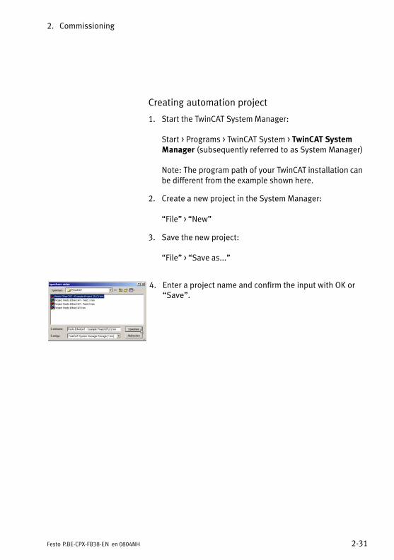
Creating automation project
1. Start the TwinCAT System Manager:
Start > Programs > TwinCAT System > TwinCAT SystemManager (subsequently referred to as System Manager)
Note: The program path of your TwinCAT installation canbe different from the example shown here.
2. Create a new project in the System Manager:
�File" > �New"
3. Save the new project:
�File" > �Save as..."
4. Enter a project name and confirm the input with OK or�Save".

2. Commissioning
2−32 Festo P.BE−CPX−FB38−EN en 0804NH
Adding field device (�Box"), e.g. CPX bus node
1. Ensure that the configuration mode (�Config Mode") isactivated. The System Manager displays the activatedConfig Mode within the TwinCAT program window onthe lower right.
2. In case the Config Mode is not activated.
Click the corresponding symbol (see adjoining figure inthe margin) or press [Shift] + [F4] to switch over to theConfig Mode.
3. Except for �Activate Free Run", confirm all subsequentqueries with Yes (�Ja"):
���Restart TwinCAT TwinCAT System in Config Mode"���Load I/O Devices"
4. Using the right mouse button, click on the device icon,here �Device 1 (EtherCAT)".
A function menu opens.

2. Commissioning
2−33Festo P.BE−CPX−FB38−EN en 0804NH
5. Select �Scan Boxes".
The System Manager searches to find field Devices(�Boxes").
The field Devices (here �Box 1") are listed belowthe related device entry (here �Device 1"): see subsequent figure in the margin.
6. Using the left mouse button, click on the box icon,here �Box 1 (CPX−FB38 64 Byte)", to display the relatedproperties, e.g. EtherCAT−specific settings or processdata.
The properties are displayed in the right area of theSystem Manager window.
� You will find EtherCAT−specific settings, e.g. EtherCATcharacteristics of the box or bus node in:
EtherCAT > �Advanced Settings"
� Typically, changes of the box properties are not required.
7. If the box properties are not displayed:
Use the display function �Split" to set the windowpartition:
�View" > �Split"
2. Commissioning
2−34 Festo P.BE−CPX−FB38−EN en 0804NH
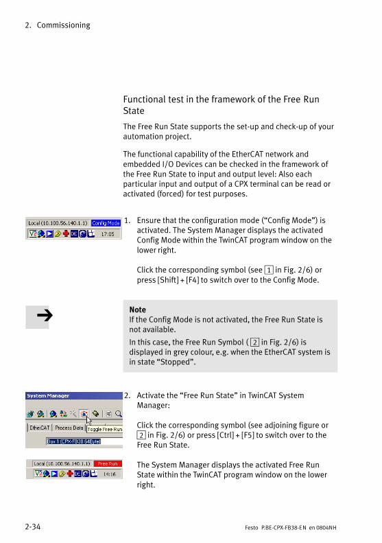
Functional test in the framework of the Free RunState
The Free Run State supports the set−up and check−up of yourautomation project.
The functional capability of the EtherCAT network andembedded I/O Devices can be checked in the framework ofthe Free Run State to input and output level: Also eachparticular input and output of a CPX terminal can be read oractivated (forced) for test purposes.
1. Ensure that the configuration mode (�Config Mode") isactivated. The System Manager displays the activatedConfig Mode within the TwinCAT program window on thelower right.
Click the corresponding symbol (see 1 in Fig.�2/6) orpress [Shift] + [F4] to switch over to the Config Mode.
NoteIf the Config Mode is not activated, the Free Run State isnot available.
In this case, the Free Run Symbol (�2 in Fig.�2/6) isdisplayed in grey colour, e.g. when the EtherCAT system isin state �Stopped".
2. Activate the �Free Run State" in TwinCAT SystemManager:
Click the corresponding symbol (see adjoining figure or2 in Fig.�2/6) or press [Ctrl] + [F5] to switch over to theFree Run State.
The System Manager displays the activated Free RunState within the TwinCAT program window on the lowerright.

2. Commissioning
2−35Festo P.BE−CPX−FB38−EN en 0804NH
1 2
3 6 87
4 5
Fig.�2/6: Functional test in the frame work of the Free Run State
3. Select the input or output to be checked (see 3 in Fig.�2/6):
Using the left mouse button, click on the symbolrepresenting the input or output, here �Valves(Example)", to display the related properties.
The properties are displayed in the right area of theSystem Manager window.

2. Commissioning
2−36 Festo P.BE−CPX−FB38−EN en 0804NH
4. Click on �Online" 4 to display the current input or outputdata or the corresponding �Value".
In the bottom part of the window, the current value isdisplayed graphically: see 8 in Fig.�2/6.
5. Click on �Write" 5 to change the value.
The window �Set Value Dialog" 6 is displayed.
6. Enter the required value.
7. Confirm your entry with �OK" 7.
8. The current value changes accordingly: see graphicalrepresentation 8. In this example, the �Valves" of aCPX�terminal are set.
9. Check the execution of the value change directly at theterminal.
2.4.4 Linking automation project (PLC project)
By means of its �Inputs" and �Outputs", i.e. registers andobjects, the PLC project forms the software interface betweenthe automation program and the inputs and outputs of theEtherCAT network, i.e. the I/O Devices and �Boxes".
The integration of an EtherCAT automation project into thesystem environment, here Beckhoff TwinCAT, is implementedusing logical interconnections (links). For this purpose, theparticular hardware elements, I/O Devices and �Boxes" arelinked to software elements (see example in Fig.�2/7).
The varied functions and options of the TwinCAT system formthereby the basis for EtherCAT automation projects providingmultitudinous optimization opportunities.
Example projects (�Samples") and master projects (�Tem�plates") are available in the TwinCAT directory of your�systemenvironment or using the TwinCAT help or the �TwinCAT Information System" (requires separate software installation).

2. Commissioning
2−37Festo P.BE−CPX−FB38−EN en 0804NH
Fig.�2/7: Linking of the EtherCAT network with a TwinCAT automation project or�PLC�project" (example)

2. Commissioning
2−38 Festo P.BE−CPX−FB38−EN en 0804NH
You can obtain the software for the �TwinCAT InformationSystem" in the internet at:
� http://www.Beckhoff.de
Detailed information as well as example projects and masterprojects can be retrieved using the following keywords:
� �PLC", �Project", �Library", �Sample", �Configuration",�Template", �Tutorial" etc.
For further support, please contact your Festo service, e.g.by�mail:
2.4.5 EtherCAT topology representation
Symbolic representationof the EtherCAT topologyand the CPX terminal
The topology display represents the structure of theEtherCAT network and the �Devices" and �Boxes", e.g. the CPX bus node and the corresponding CPX terminal(�4 in Fig.�2/8).
The subsequent explanation describes the calling of thetopology display using Beckhoff TwinCAT.
Please noteThe topology display however is first available aftercompletion of the EtherCAT network configuration.
The network configuration is described in section 2.4.3.

2. Commissioning
2−39Festo P.BE−CPX−FB38−EN en 0804NH
1 24 3
Fig.�2/8: EtherCAT topology display
1. In TwinCAT System Manager, click on the device symbol ofthe bus node 1 to display the device properties.
2. In the device properties windows, click on �EtherCAT" 2to open the EtherCAT tab.
3. Click on �Topology" 3:
A separate window displays the topology of the EtherCATnetwork and the �Devices" and �Boxes", e.g. the CPX busnode and the corresponding CPX terminal 4.

2. Commissioning
2−40 Festo P.BE−CPX−FB38−EN en 0804NH
2.4.6 Configuration in the Remote Controller operating mode
If there is a CPX−FEC in your CPX terminal, you can operatethe bus node in the Remote Controller operating mode. The bus node then occupies 8 input bytes and 8 outputbytes. These are available to the control program in theCPX−FEC and the EtherCAT Master (IPC/PLC).
Configuration in theRemote Controller busnode operating mode
1. Make sure that DIL switch DIL 1.1 of the bus node is inthe remote controller position (DIL 1.1 = ON, DIL 1.2 = OFF; see section 1.2.2, Tab.�1/1).
As a result, the bus node CPX−FB38 is configured as aremote controller.
To configure the CPX−FEC and CPX terminal, the use ofFesto Software Tools Version 4 (FST 4) is required(see�step 2.).
2. Configure the CPX terminal with the Festo Software ToolsFST 4 via the CPX−FEC.
3. Start your configuration and programming software,e.g.�Beckhoff TwinCAT.
4. Open the hardware configuration (I/O Configuration).
5. Configure the EtherCAT network.

2. Commissioning
2−41Festo P.BE−CPX−FB38−EN en 0804NH
2.5 Parameterisation
2.5.1 Introduction to parameterisation
The system reaction of a CPX terminal can be largely adaptedto the relevant application. You can individually set the reac�tion of the entire terminal as well as of individual modulesand channels through parameterisation. A distinction is madebetween the following�parameterisation functions:
� System parameterisation, e.g. switching off faultmessages, setting reaction times
� Module parameterisation (module− and channel−specific),e.g. monitoring functions, settings for error handling,settings for forcing
� Parameterising the diagnostics memory.
A detailed description of the individual parameters as well asbasic information on application can be found in the CPXsystem manual (P.BE−CPX−SYS−...).
Which parameters are available for the used modules areexplained in the manual for the respective module, e.g.manual for CPX I/O modules (P.BE−CPX−EA−...). An example ofapplication can be found in section 2.7.
Please noteThe CPX terminal is supplied with factory−presetparameters (default parameterisation).
Please notePlease observe the specific notes on parameterising thebus node CPX−FB38 in section 2.5.3.

2. Commissioning
2−42 Festo P.BE−CPX−FB38−EN en 0804NH
CautionChanges in parameterisation or application−specific pa�ramter settings result in changes to the module or systembehaviour. Check especially when replacing CPX terminalsto see which settings are necessary and make sure thatthese are restored, if necessary (e.g. in the start−up phaseby appropriate system−start parameterisation).
WarningUndesired activation of actuators!
An incorrect status of the valves and outputs can lead todangerous situations.
· Make sure that valves and outputs are put into a safestate when faults occur.
· Check within the framework of your EMERGENCY STOPconcept and the�Fail safe setting to ascertain themeasures necessary for putting your machine/systeminto a safe state (see also section 2.6.1).
Typical safety measures for safe system condition:
� switching off the load voltage for the valves and outputmodules in the secondary circuit of the power unit
� switching off the compressed air supply for the valveterminal.
Due to energy stored in the input circuitry of valve ter�minals, there may be a delayed reaction of the valves whenthe load voltage is switched off.
Take this situation into account, for example by:
� using an input signal in the controller for checkingwhether the load voltage has been switched off
� blocking the control signal for the valves by locking theoutput signal with the input signal �Load voltage".

2. Commissioning
2−43Festo P.BE−CPX−FB38−EN en 0804NH
2.5.2 General prerequisite for parameterisation
Please noteA CPX terminal can only be parameterised if the function�System start with default parameterisation and currentCPX expansion" is activated (set �System start" systemparameter accordingly).
With the �System start" system parameter, you candetermine the starting reaction of the CPX terminal. Select the�System start with default parameterisation and current CPXexpansion" setting to permit the required parameterisation.To perform the parameterisation, use the CPX−FMT orCPX−MMI. If the parameterisation is not changed, the factorysettings are used.
After parameterisation, you change the setting of the�System�start" system parameter to �System start with savedparameterisation and saved CPX expansion". This fixes thesettings and stores them in the module.
After a new start of the CPX terminal, the bus node diagnosticLED �Modify" (M) lights up permanently. The terminal usesthe saved parameter settings.
CautionIn the case of CPX terminals on which the M LED lights uppermanently, parameterisation will not be restored auto�matically by the higher−order system upon replacement. In these cases, check before replacement to see whichsettings are required and carry out these settings.

2. Commissioning
2−44 Festo P.BE−CPX−FB38−EN en 0804NH
2.5.3 Methods of parameterisation
A CPX terminal with bus node CPX−FB38 can be parameterisedin various ways. A brief explanation of the available methodscan be found in Tab.�2/15 and the following sections.
Parameterisation of the CPX terminal via a PLC user programor EtherCAT configuration and programming software, e.g.Beckhoff TwinCAT, is not possible.
Methods and description Advantages Disadvantages
Method 1: Parametrizing via the FestoMaintenance Tool (CPX−FMT)Menu−guided parameter entries viaPC software (by means of USBadapter)
� Easy parameter entryguided by menu in plaintext
� Parameterisation is savedlocally in the CPX terminaland is lost if the CPXterminal or bus node isreplaced. 1)
Method 2: Parameterisation with thehandheld unit (CPX−MMI)Menu−guided parameter entry
� Easy parameter entryguided by menu in plaintext using a compacthandheld unit
� Parameterisation is savedlocally in the CPX terminaland is lost if the CPXterminal or bus node isreplaced. 1)
1) Copying and saving of parameter settings is possible, such as for transmission of parameter data as part of a module exchange.
Tab.�2/15: Methods of parameterisation (overview)

2. Commissioning
2−45Festo P.BE−CPX−FB38−EN en 0804NH
2.5.4 Parameterisation via the Festo Maintenance Tool (method 1)
With the PC software Festo Maintenance Tool (CPX−FMT), you can easily parameterise the CPX terminal over a USBconnection.
You receive the necessary USB adapter with the CPX−FMTsoftware.
2.5.5 Parameterisation with the handheld unit (method 2)
The Festo handheld unit (CPX−MMI) offers menu−guidedaccess for parameterisation without configuration software.
Information about general operation of the handheld unit canbe found in the related manual (P.BE−CPX−MMI−1−...).
Please noteThe last parameterisation set or received in the CPX terminal is always valid.

2. Commissioning
2−46 Festo P.BE−CPX−FB38−EN en 0804NH
A CPX terminal can only be parameterised if the function�System start with default parameterisation and current CPXexpansion" is activated (set �System start" system parameteraccordingly).
In this case, the factory−set parameter settings are valid in theCPX terminal after the power supply is switched on(Power�ON).
If you wish to specifically change individual parameter values� without inputting again settings that have already beenmade:
1. �Approve" parameterisation (permit), that is, activatefunction �System start with default programming andcurrent CPX expansion" (see above).
2. Do NOT restart system or CPX terminal (this ensures thatparameterisation already performed is not reset to factorysettings).
3. Change or enter parameters.
4. �Block" parameterisation again, that is, activate function�System start with saved parameterisation and saved CPXexpansion".
Please noteChange the setting of the system parameter �System start"to �System start with saved parameterisation and savedCPX expansion" after completion of parameter entry toensure that parameterisation remains intact even after asystem restart or after changes to the control program (of the higher−level system controller).
If the function �System start with saved parameterisationand saved CPX expansion" is activated, the entered orchanged parameter settings become valid immediatelyafter the power supply is switched on (Power ON).

2. Commissioning
2−47Festo P.BE−CPX−FB38−EN en 0804NH
2.6 Remarks on parameters of the CPX system settings
2.6.1 Parameterisation of the Fail safe mode
Fail safe mode
This operating mode defines the status which digital outputsignals (outputs and valves) are to assume in the event offield bus communication faults.
You can determine the status to be assumed for each outputchannel (output or solenoid coil or valve) separately. Thestandard setting is �Reset output channel".
Without parameterisation of the output channels, thefollowing communication condition applies:
� Input signals are transferred.
� Output signals are reset (factory setting); note that foranalogue outputs, the analogue value 0 is set.

2. Commissioning
2−48 Festo P.BE−CPX−FB38−EN en 0804NH
Behaviour of the outputs in the Fail safe mode(parameterisation)
In the Fail safe mode, output channels can assume one of thefollowing states:
Digital outputs/valves Analogue outputs
Maintaining the currentcondition (�freeze" signal)
Maintaining the currentcondition (�freeze" signal)
Resetting the output channel(factory setting)
Resetting of the output channelto the analogue value 0(factory�setting)
Setting the output signal Setting the required analoguevalue (output signal)
Tab.�2/16: Possible states of the output channels in theFail�safe mode
If necessary, parameterise the required state of individual orall output channels (outputs or solenoid coils or valves).
The status is set with the channel−specific module parameters�Faul mode" and Fault state".
In doing so, make sure that you assign the suitable setting toeach output.
Further information: see CPX system manual P.BE−CPX−SYS−...

2. Commissioning
2−49Festo P.BE−CPX−FB38−EN en 0804NH
2.6.2 CPX−FB38−specific process of start parameterisation duringswitching on (system start)
Due to the CPX−FB38−specific limitations regarding para�meterisation (no parameterization by means of the higher−level controller), start parameters can only be entered usingthe handheld display (CPX−MMI) or Festo Maintenance Tool(CPX−FMT).
The parameterisation during system start of the CPX terminalis�therefore dependent on the setting of the system startparameter stored in the bus node. This parameter establisheswhether the start parameterisation is loaded by the con�troller, the master or the FEC, or from the CPX bus node.
In the Festo Maintenance Tool, you will find the correspondingsetting under �CPX" � �System settings", register �Systemparameters" � �System start": After the required startparameters are set, choose the system start option �Savedparameters".
Process details can be found in Fig.�2/9 and the followingexplanations.
Substantial differences from the standard process:
� No start parameterisation by means of the controller ormaster, but possibly by means of the CPX−FEC controllerprogram (FEC in the remote controller operating mode).
� Process with �default parameter set" uses the factory−programmed default parameter set (standard processuses in this case the parameterisation from the field buscontrol program).
Further information on parameterisation using CPX−FMT orCPX−MMI can be found in the sections 2.5.4 and 2.5.5.

2. Commissioning
2−50 Festo P.BE−CPX−FB38−EN en 0804NH
2
1
EtherCATcontroller/Master (IPC...)
EtherCATI/O controller(if necessary CPX−FEC)
3
1 With default parameter set:The controller or the I/O Controller initiates use of the factory−programmeddefault parameter set; the bus node then distributes the parameter set to themodules.
2 With saved parameter set:The CPX bus node distributes the parameter set saved in the bus node, whichmay have been changed or adapted by means of CPX−MMI or CPX−FMT.
3 With �default" parameter set using a CPX−FEC in the remote controller operatingmode (parameterisation from the control program of the FEC): The CPX−FEC loads the programmed start parameter set into the CPX bus node;the bus node then distributes the parameter set to the modules.
Fig.�2/9: Sequence of start parameterisation during switch−on of a CPX terminal withbus node CPX−FB38

2. Commissioning
2−51Festo P.BE−CPX−FB38−EN en 0804NH
2.7 Application example for the parameterisation
1 Input for1st�sensor (with defaultparameterisation)
2 Parameterisedinput for2nd�sensor (see text)
Î Î
21
1. Sensor
2. Sensor
Fig.�2/10: Application example for parameterisation of the input debounce time andsignal extension time on the 2nd sensor
In the above application, packets are transported on afast−moving conveyor belt.
The input for the 2nd sensor is parameterised as follows forimprovement of the signal recording and processing:
� Reduction of the input debounce time from 3�ms (factorysetting) to 0.1�ms: Recording shorter signals is possible.
This parameter is set for the complete module.
� Signal extension time set to 50�ms: Reliable recording ofthe signals by the controller.
The value of this parameter is set for the completemodule but must be activated or deactivated separatelyfor each input channel.

2. Commissioning
2−52 Festo P.BE−CPX−FB38−EN en 0804NH
2.8 Checklist for starting up the CPX terminal
Providing the safety concept of your machine/system per�mits, start up the CPX terminal with both operating voltages �but without compressed air. In this way, you can then test theCPX terminal without triggering unintended reactions.
Please notePay attention to start−up information!
Please observe the general start−up instructions in the CPXsystem manual (P.BE−CPX−SYS−...) and in the manual ofyour controller.
CautionUndesired activation of actuators!
An incorrect status of the valves and outputs can lead todangerous situations!
The CPX terminal with bus node for EtherCAT also startswith incomplete configuration.
Check the configuration and address assignment of theI/Os on the CPX terminal.In order to do this, you can, if necessary, force the I/Os(see CPX system manual).
2. Commissioning
2−53Festo P.BE−CPX−FB38−EN en 0804NH
Proceed as follows
· Check the DIL switch settings as well as the hardware andnetwork configuration before using and replacing the busnode or CPX terminal.
· Make sure that the desired parameterisation of the CPXterminal is automatically carried out in the �start−up"phase, that is, during initialisation (EtherCAT statusInitialisation), (see section 2.6.2).
Please notePerform configuration and parameterisation again after amodule replacement!
Recreate the necessary hardware and network configur�ation and CPX terminal parameterisation after replacementof the bus node or CPX terminal.
To do this, use the EtherCAT controller or the FestoMaintenance Tool (CPX−FMT) or handheld unit (CPX−MMI).
CPX−specific configuration and parameter data can beentered only with CPX−FMT or CPX−MMI.
· Check the parameterisation, using spot checks ifnecessary.
2. Commissioning
2−54 Festo P.BE−CPX−FB38−EN en 0804NH
2.9 Bus node replacement
Procedure
1. Stop the process controller (PLC/Master):
2. If necessary, disconnect the power supply andcompressed air supply.
3. Replace the bus node (Dismantling/Installation: see section 1.1).
4. Switch the power supply back on.
5. Start your configuration and programming software(e.g.�Beckhoff TwinCAT).
6. Perform a new configuration (hardware and networkconfiguration).
7. Start the process controller (PLC/Master); choose theEtherCAT operating status Pre−operational (networkconfiguration).
The controller loads all required EtherCAT data into thebus node.
8. Recreate the required parameterisation; to do this, use the CPX−MMI or CPX−FMT.
9. If necessary, switch the compressed air supply back on.
10. Start the program process (PLC/Master); choose theEtherCAT operating status Operational.
The�CPX terminal or your EtherCAT system is again innormal operating condition.

Diagnosis
3−1Festo P.BE−CPX−FB38−EN en 0804NH
Chapter 3

3. Diagnosis
3−2 Festo P.BE−CPX−FB38−EN en 0804NH
Contents
3. Diagnosis 3−1 . . . . . . . . . . . . . . . . . . . . . . . . . . . . . . . . . . . . . . . . . . . . . . . . . . . . .
3.1 Overview of diagnostic possibilities 3−3 . . . . . . . . . . . . . . . . . . . . . . . . . . . . . . . .
3.2 Diagnostics via LEDs 3−6 . . . . . . . . . . . . . . . . . . . . . . . . . . . . . . . . . . . . . . . . . . . .
3.2.1 EtherCAT operating status display (LED run),EtherCAT�error�(LED�Error),�connection status (LEDs L/A2, L/A1) 3−8 . . . . . . . . . . . . . . . . . . . . . . . . . . . . . . . . . . . . . . .
3.2.2 Fault displays of the LEDs for system diagnosis (LED PS, PL, SF, M) 3−10 . . . . . . . . . . . . . . . . . . . . . . . . . . . . . . . . . . . . . . .
3.3 Diagnostics via status bits 3−13 . . . . . . . . . . . . . . . . . . . . . . . . . . . . . . . . . . . . . . . .
3.4 Diagnostics via the I/O diagnostic interface (STI) 3−15 . . . . . . . . . . . . . . . . . . . . .
3.5 Diagnosis via EtherCAT 3−17 . . . . . . . . . . . . . . . . . . . . . . . . . . . . . . . . . . . . . . . . . .
3.5.1 Basic information 3−17 . . . . . . . . . . . . . . . . . . . . . . . . . . . . . . . . . . . . . . . .
3.5.2 Fail safe behaviour (Fail safe settings) 3−18 . . . . . . . . . . . . . . . . . . . . . . .
3.5.3 Fault types 3−20 . . . . . . . . . . . . . . . . . . . . . . . . . . . . . . . . . . . . . . . . . . . . .

3. Diagnosis
3−3Festo P.BE−CPX−FB38−EN en 0804NH
3.1 Overview of diagnostic possibilities
The CPX terminal provides extensive and user−friendlypossibilities for diagnostics and error handling. The followingoptions are available depending on �the configuration:
Diagnosticoption
Brief description Advantages Detaileddescription
LED display The LEDs show configurationfaults, hardware faults, busfaults, etc. immediately.
Fast �on−the−spot"recognition of faults
Section 3.2
Status bits Internal inputs, which supplycoded common diagnosticmessages; the 8 status bitsare cyclically transmitted tothe module as �inputs" withthe normal inputs.
Fast access to faultmessages in the PLCuser program regardlessof the module and I/Ocontroller
Section 3.3
I/O diagnosticinterface
Bus−independent diagnosticinterface at I/O level whichenables access to the internaldata of the CPX terminal; forthis function, 16 inputs and16 outputs (2 byte) areavailable.
Read access to internalparameters and data atI/O level
CPX system manual,section ondiagnostics andfault clearance(P.BE−CPX−SYS−...),instructions insection 3.4(P.BE−CPX−FB38−...)
Diagnostics viathe handheldunit
Diagnostic information can beshown on the handheld unit ina user−friendly manner bymeans of menus.
Fast �on−the−spot"recognition of faults inplain text withoutprogramming
Manual for thehandheld unit(P.BE−CPX−MMI−1−...)
Tab.�3/1: Overview of the diagnostic options of the CPX terminal

3. Diagnosis
3−4 Festo P.BE−CPX−FB38−EN en 0804NH
Please noteAvailability of diagnosis information
Note that the diagnostic information shown depends onthe settings (see section 1.2.2) and the parameterisation(see section 2.5) of the CPX terminal.
· Make sure that, in particular, system and module para�meters are set so that the required information is passedon to the higher−level control system (PLC, SPS or IPC).
Usage case example:System parameters SCS/SCO/SCV, VOUT/VAL*)
The short−circuitoverload and undervoltage diagnosticmessages for the complete CPX terminal can besuppressed using the monitoring system parameter(function�no. 4401).
The settings made separately for each module with themodule parameter CPX module monitoring are notaffected by the setting of the system parametersmonitoring. The �local" setting of the module parametersremains until there is a change in the �global" systemparameter.
But diagnostic messages of the monitoring module,e.g.�short−circuit error messages, are only forwarded to thecontrol system if the system parameter is activated.
Additional information on parameterisation can be foundin the CPX system manual (P.BE−CPX−SYS−...) in appendix B.
*) SCS short circuit/overload � sensor/logic provisionSCO short circuit/overload � outputs (load supply)SCO short circuit/overload � valves (load supply)VOUT/VAL undervoltage � outputs/valves (load supply)

3. Diagnosis
3−5Festo P.BE−CPX−FB38−EN en 0804NH
WarningUndesired activation of actuators!
An incorrect status of the valves and outputs can lead todangerous situations!
· Make sure that valves and outputs are put into a safestate when faults occur.
· Check within the framework of your EMERGENCY STOPconcept and the�fail−safe setting to ascertain themeasures necessary for putting your machine or systeminto a safe state.
Typical safety measures for safe system condition:
� switching off the load voltage for the valves and outputmodules in the secondary circuit of the power unit.
� switching off the compressed air supply for the valveterminal.
Due to energy stored in the input circuitry of valve ter�minals, there may be a delayed reaction of the valves whenthe load voltage is switched off.
Take this situation into account, for example by:
� using an input signal in the controller for checkingwhether the load voltage has been switched off.
� blocking the control signal for the valves by locking theoutput signal with the input signal �Load voltage".

3. Diagnosis
3−6 Festo P.BE−CPX−FB38−EN en 0804NH
3.2 Diagnostics via LEDs
LEDs for diagnosing the CPX terminal are available on the busnode as well as on the individual modules.
The meaning of the LEDs on the electric modules can befound in the manual for the relevant module.
LEDs on the CPX bus node for EtherCAT
The light emitting diodes on the cover indicate the operatingstatus of the CPX bus node.
1 CPX−specific LEDs
PS: Power system
PL: Power load
SF: System Failure
M: Modify
2 EtherCAT−specificLEDs
Run: EtherCAT operating status
Error: EtherCAT errors
L/A2: Connection status (link/activity) Out2
L/A2: Connection status (link/activity) In1
Error
1
2
PS
PM
SF
Run
Error
L/A2
ML/A1
PS
PM
SF
Run
L/A2
ML/A1
Fig.�3/1: LEDs on the CPX bus node

3. Diagnosis
3−7Festo P.BE−CPX−FB38−EN en 0804NH
The LEDs are shown in their various states as follows:
lights; flashes or flickers; off
Normal operating status
In normal operating status, the following LEDs light green:Run, PS and PL; the LEDs L/A1 and L/A2 light up or flashgreen when the connection is used. The error and SF LEDs donot light up.
The M LED only lights or flashes for the changed parameter�isation setting (system start with saved parameterisation andsaved CPX expansion) or force active (force mode, functionNo. 4402; see CPX System Manual P.BE−CPX−SYS−..., onsitediagnostics).
LED display Operatingstatus
PS
PM
SF
Run
Error
L/A2
ML/A1
The following LEDslight green:� Run� PS� PM� L/A2 1)
� L/A1 1)
The following LEDsdo not light:� Error� SF
The M LED lights orflashes if para�meterisation ischanged or forcemode is active
Standard
1) Only if connection is used: � Constant light: connection active� Flashing/blinking: Data transmission is running
Tab.�3/2: Normal operating status

3. Diagnosis
3−8 Festo P.BE−CPX−FB38−EN en 0804NH
3.2.1 EtherCAT operating status display (LED run),EtherCAT�error�(LED�Error),�connection status (LEDs L/A2, L/A1)
Run � EtherCAT operating status (communication status)
LED (green) Sequence Status Meaning/error handling
LED is off
ON
OFFInit Bus node is in the the Init status (normal condi�
tion after switch−on or after a restart or reboot)
LED flashes
ON
OFFPre−operational Bus node is in the pre−operational status
(network configuration)
LED flashes 1x 1)
ON
OFF
Safe−operational Bus node is in the safe−operational status(e.g.�due to a network disturbance). Only theinput signals (e.g. sensor data) are updated.Outputs and valves maintain the current state(signal is �frozen").
LED lights up
ON
OFFOperational Bus node is in the Operational status
(normal operating status)
LED flickers
ON
OFFInitialisation Bus node carries out a restart (reboot) and is not
yet in the Init status (designated as Initialisationstatus)
1) One−time short flashing (1x flash, pause, 1x flash, etc.) is designated as single flash.
Tab.�3/3: Fault diagnosis with the Run LED

3. Diagnosis
3−9Festo P.BE−CPX−FB38−EN en 0804NH
Error � EtherCAT error (communication error)
LED (red) Sequence Status Meaning/error handling
LED is off
ON
OFFNo fault EtherCAT communication of the
bus node is in normal operatingstate
LED flashes
ON
OFFInvalid configuration
No connection to the EtherCATnetwork
Possible causes:� Cable/connection
disconnected (interrupted)� Device has no connection
to the EtherCAT Master (for control)
� Master is not active
Error handling � check:
· The network connection(interrupted, short−circuited ordisturbed network connection)
· The configuration, in particularthe physical and logical positionand addressing of the bus node
Tab.�3/4: Fault diagnosis with the LED error
L/A2, L/A1 � Connection status (link/activity) Out2/In1
LED (green) Sequence Status Meaning/error handling
LED is off
ON
OFFNo physical networkconnection
Check network connection / network cable
LED lights up
ON
OFFNetwork connection OK �
LED flickers 1)
ON
OFF
Flickering: Datatransmission is running
�
1) Rapid flickering seems to be lighting; the light intensity depends on the data traffic
Tab.�3/5: Fault diagnosis with the LEDs L/A2, L/A1

3. Diagnosis
3−10 Festo P.BE−CPX−FB38−EN en 0804NH
3.2.2 Fault displays of the LEDs for system diagnosis (LED PS, PL, SF, M)
PS (power system) � power sensor/logic supply
LED (green) Sequence Status Fault treatment
LED lights up
ON
OFF
No fault, operatingvoltage/sensor supplyapplied
�
LED flashes
ON
OFFOperating voltage/sensorsupply outside thetolerance range
1. Eliminate short circuit/overload2. Dependent on the parameterisation:
· The sensor supply voltage will beswitched on again automaticallyafter the short circuit has beeneliminated (default)
· Power Off/On is necessary
LED is off
ON
OFF
The operating voltage/sensor supply is notapplied
Check the operating voltage connectionof the electronics
Tab.�3/6: Fault diagnosis with the LED PS
PL (Power Load) � power load supply (outputs/valves)
LED (green) Sequence Status Fault treatment
LED lights up
ON
OFF
No fault, load voltageapplied
None
LED flashes
ON
OFFLoad voltage outsidetolerance range
1. Eliminate undervoltage2. Dependent on the parameterisation:
· The load voltage supply will beswitched on again automaticallyafter the undervoltage has beeneliminated (default)
· Power Off/On is necessary
Tab.�3/7: Fault diagnosis with the LED PL

3. Diagnosis
3−11Festo P.BE−CPX−FB38−EN en 0804NH
SF (system failure) � system fault
LED (red) Sequence Status 1) Meaning/error handling
LED is off
ON
OFFNo fault �
LED flashesonce
ON
OFFMinor error or information(error class 1)
See description of the errornumbers in the CPX system manual(P.BE−CPX−SYS−...)
LED flashestwice
ON
OFF
Error (error class 2)
LED flashesthree times
ON
OFF
Serious error (error class 3)
1) The system error LED flashes depending on the class of error which has occurred.Error class 1 (minor error): one flash, pauseError class 2 (error): flash twice, pauseError class 3 (serious error): flash three times, pause
Tab.�3/8: Fault diagnostics using the SF LED

3. Diagnosis
3−12 Festo P.BE−CPX−FB38−EN en 0804NH
M (modify) � parameterising modified or forcing active
LED (yellow) Sequence Status Meaning/error handling
LED is off
ON
OFF
System start with defaultparameterisation (factorysetting) and current CPXexpansion has been set;external parameterisationpossible (presetting)
None
LED lights up
ON
OFF
System start with savedparameterisation andsaved CPX expansion hasbeen set;parameters and CPXexpansion are retained;external parameterisationis blocked 1)
Be careful when replacing CPX ter�minals with saved parameterisation:Parameterisation is not carried outautomatically for these CPX terminalsby the higher−order controller whenthe terminal is replaced. In thesecases, check which settings arerequired before the replacement andmake these settings if necessary.
LED flashes
ON
OFFForce is active 1) The Force function has been activated
(Force mode; Function No. 4402, seeCPX System Manual P.BE−CPX−SYS−...).
1) The display of the Force function (LED flashes) has priority over the display of the setting for thesystem start (LED lights).
Tab.�3/9: Messages of the LED M

3. Diagnosis
3−13Festo P.BE−CPX−FB38−EN en 0804NH
3.3 Diagnostics via status bits
The CPX terminal provides 8 status bits if you�activate�thisfunction using DIL switches (see section 1.2.2).
The status bits are used for displaying common diagnosticsmessages (global error messages). Status bits are configuredlike inputs. If the status bits function is activated, it occupiesthe first 16 inputs in the address range (8 inputs or 8 bitsremain unused; see Tab.�1/2 or Tab.�2/1).
Please noteNote the instructions on addressing and configuration inthe sections 2.3 and 2.4.
The following table provides an overview of the availablediagnostic information.
Bit Diagnostic information with1−signal
Manual
0 Fault at valve or pneumatic module Module type in whicha fault has occurred
1 Fault on output modulea fault has occurred.
2 Fault on input module
3 Fault on analogue module ortechnology module
4 Undervoltage Type of fault
5 Short circuit/overload
6 Wire break
7 Other faults
Tab.�3/10: Overview Status bits of the CPX bus node(optional)

3. Diagnosis
3−14 Festo P.BE−CPX−FB38−EN en 0804NH
If all status bits supply a 0−signal, no fault will be registered.If, in contrast, a status bit supplies a 1 −signal, there is a fault.
If various faults occur simultaneously on various types ofmodules, these faults cannot be assigned via the status bits.In contrast, faults can be uniquely determined via the I/Odiagnostic interface.
Diagnostic information or error messages of the status bitsfunctions (or I/O diagnostic interface) can be read out usingthe handheld unit (CPX−MMI), Festo Maintenance Tool(CPX−FMT) and via the EtherCAT network.
Please noteLimited availability of diagnosis information
Status bits forwarded over the EtherCAT network, that is,diagnostic information or error messages of the CPXterminal, are almost always not displayed in EtherCATconfiguration and programming software, e.g. TwinCAT.
Display of CPX−specific diagnostic information and errormessages in the online mode of the EtherCAT software isavailable � to a limited extent � only by means of the I/Odiagnostic interface.
Use the handheld unit, the Festo Maintenance Tool or yourrequirements according to application programs fordetailed diagnostic functions.
Further instructions on the function and content of the statusbits can be found in the CPX system manual (P.BE−CPX−SYS−...)in the Diagnostics and error handling section.

3. Diagnosis
3−15Festo P.BE−CPX−FB38−EN en 0804NH
3.4 Diagnostics via the I/O diagnostic interface (STI)
The CPX terminal provides 16 I/O status bits (System tableinterface, STI) if you activate this function using DIL switches(see section 1.2.2).
Detailed diagnostic information can be accessed via the I/Odiagnostic interface. You can ascertain this exactly, e.g. bynoting on which module and channel a fault has occurred.16�input bits and 16 output bits, via which all diagnostic datacan be read, are available for accessing the system diagnosis.
If the I/O diagnostic interface is active, it will occupy the first16 inputs and outputs in the address range (see Tab.�1/2 andTab.�2/1).
Please noteNote the instructions on addressing and configuration inthe sections 2.3 and 2.4.
The following table provides an overview of the availablediagnostic information.
Diagnostic data Contents/description
Global diagnostic data � General overview of faults
Module diagnostic data � Detail diagnosis per module
Status of diagnosticmemory
� Number of entries in the diagnosticmemory
� Operation mode
Diagnostic memory data � Long−term memory� Detail diagnosis + relative time
stamp per fault event
Tab.�3/11: Overview of diagnosis data or I/O diagnosticinterface (optional)

3. Diagnosis
3−16 Festo P.BE−CPX−FB38−EN en 0804NH
Diagnostic information or error messages of the status bitsfunctions (or I/O diagnostic interface) can be read out usingthe handheld unit (CPX−MMI), Festo Maintenance Tool(CPX−FMT) and via the EtherCAT network.
Please noteLimited availability of diagnosis information
Diagnostic information or error messages of theCPX�terminal are almost always only displayed in EtherCATconfiguration and programming software, e.g. TwinCAT.
Use the handheld unit, the Festo Maintenance Tool or yourrequirements according to application programs fordetailed diagnostic functions.
Further instructions on the I/O diagnosis interface (diagnosticinformation, function numbers) can be found in the CPXsystem manual (P.BE−CPX−SYS−...) in the Diagnostics and errorhandling section.

3. Diagnosis
3−17Festo P.BE−CPX−FB38−EN en 0804NH
3.5 Diagnosis via EtherCAT
3.5.1 Basic information
Please noteAvailability of diagnosis information via the EtherCATnetwork
� Note that the diagnostic information shown depends onthe settings (see section 1.2.2) and the parameterisation(see section 2.5) of the CPX terminal (see also section 3.1).
� Detailed diagnosis information about the status ofthe�CPX terminal are available to the EtherCAT networkonly by means of the I/O diagnosis interface.
� Activate the I/O diagnosis interface to ensure that errormessages of the CPX terminal are automaticallydisplayed in the EtherCAT configuration software,e.g.�Beckhoff TwinCAT.
� Diagnostics information is availabie to Beckhoff TwinCATonly to a limited extent even�with activated I/O diagnosisinterface. For detailed error analysis, use the handheldunit, the Festo Maintenance Tool or your requirementsaccording to application programs for detailed diag�nostic functions.

3. Diagnosis
3−18 Festo P.BE−CPX−FB38−EN en 0804NH
3.5.2 Fail safe behaviour (Fail safe settings)
The reaction of the CPX terminal for the following errors isdependent on the configured reaction of the controller (of theMaster), i.e. of the PLC, the SPS, the IPC or the applicationprogram and the parameterised Fail safe setting:
� stop of the controller (of the master)
� network interruption
� telegram elimination.
Depending on the parameterisation, the outputs (valves andelectric outputs) will be switched off (factory setting),switched on or retain their status.
Further information about the Fails safe setting can be foundin the section 2.6.1 the CPX system manual P.BE−CPX−SYS−...
You can set two types of fault reactions of the controller (or the application program):
� Hard fault reaction:The controller switches to the operating mode �STOP" orpre−operational when a fault occurs.
� Soft fault reaction:The controller switches to the operating mode �RUN"or�safe−operational (or possibly operational) when a faultoccurs.

3. Diagnosis
3−19Festo P.BE−CPX−FB38−EN en 0804NH
WarningUndesired activation of actuators!
An incorrect status of the valves and outputs can lead todangerous situations!
· Make sure that valves and outputs are put into a safestate when faults occur.
· Check within the framework of your EMERGENCY STOPconcept and the�fail safe setting to ascertain themeasures necessary for putting your machine or systeminto a safe state.
Typical safety measures for safe system condition:
� switching off the load voltage for the valves and outputmodules in the secondary circuit of the power unit
� switching off the compressed air supply for the valveterminal.
Due to energy stored in the input circuitry of valve ter�minals, there may be a delayed reaction of the valves whenthe load voltage is switched off.
Take this situation into account, for example by:
� using an input signal in the controller for checkingwhether the load voltage has been switched off
� blocking the control signal for the valves by locking theoutput signal with the input signal �Load voltage".
3. Diagnosis
3−20 Festo P.BE−CPX−FB38−EN en 0804NH
Please noteTake into account valve behaviour as part of theEMERGENCY STOP concept or of the Fail safe setting!
If the outputs are reset in the case of a controller stop,network interruption, telegram elimination or terminaldisturbance, the following valve behaviour occurs:
� Single−solenoid valves move to the basic position.
� Double−solenoid valves remain in the current position.
� Mid−position valves move to the mid−position(depending on valve type: pressurised, exhausted orblocked).
3.5.3 Fault types
A listing of all error types as well as additional diagnosisinformation can be found in the CPX system manual(P.BE−CPX−SYS−...).

Technical appendix
A−1Festo P.BE−CPX−FB38−EN en 0804NH
Appendix A

A. Technical appendix
A−2 Festo P.BE−CPX−FB38−EN en 0804NH
Contents
A. Technical appendix A−1 . . . . . . . . . . . . . . . . . . . . . . . . . . . . . . . . . . . . . . . . . . . . .
A.1 Technical specifications of bus node CPX−FB38 A−3 . . . . . . . . . . . . . . . . . . . . . . .

A. Technical appendix
A−3Festo P.BE−CPX−FB38−EN en 0804NH
A.1 Technical specifications of bus node CPX−FB38
General information
General technical data see CPX system manual P.BE−CPX−SYS−...
Protection class through housingaccording to EN 60529, completely installed,plug connector inserted or provided withprotective cap
IP65/IP67 protection
Protection against electric shockProtection against direct and indirect contact asper IEC/DIN EN 60204−1
by means of a PELV circuit
Module code (CPX−specific)� Remote I/O� Remote controller
220169
Module identifier (in the Handheld)� Remote I/O� Remote controller
FB38−RIO EtherCAT remote I/OFB38−RC EtherCAT remote controller
Voltage supply
Operating voltage�/�load voltage see CPX system manual P.BE−CPX−SYS−...
Bus node own−current consumptionfrom operating voltage supply for electronics/sensors (VEL/SEN)
max. 80 mA at 24 V (internal electronics)
Electrical isolationEtherCAT interfaces for VEL/SEN electrically isolated
Power failure bridging time 10 ms

A. Technical appendix
A−4 Festo P.BE−CPX−FB38−EN en 0804NH
Network−specific characteristics
Field bus protocol EtherCAT, based on the Ethernet protocol (IEEE 802.3), optimised for process data Real−time−capable
Specification Standards and norms with regard to EtherCAT:� IEC 61158� IEC 61784� IEC 61918� ISO/IEC 8802−3
Further information: http://www.ethercat.org
Baud rate 100 Mbit/s
Cross−over recognition Auto−MDI
EtherCAT input/output size 64 bytes/64 bytes, regardless of operating mode

Index
B−1Festo P.BE−CPX−FB38−EN en 0804NH
Appendix B

B. Index
B−2 Festo P.BE−CPX−FB38−EN en 0804NH
Contents
B. Index B−1 . . . . . . . . . . . . . . . . . . . . . . . . . . . . . . . . . . . . . . . . . . . . . . . . . . . . . . . . .
B. Index
B−3Festo P.BE−CPX−FB38−EN en 0804NH
A
AbbreviationsProduct−specific XIII . . . . . . . . . . . . . . . . . . . . . . . . . . . . . . .
Additional power supply 1−20 . . . . . . . . . . . . . . . . . . . . . . . . .
Addressing 2−13 . . . . . . . . . . . . . . . . . . . . . . . . . . . . . . . . . . . .
Assembly 1−5 . . . . . . . . . . . . . . . . . . . . . . . . . . . . . . . . . . . . . . .
B
Beckhoff TwinCAT 2−29 . . . . . . . . . . . . . . . . . . . . . . . . . . . . . . .
C
CablesNetwork 1−15 . . . . . . . . . . . . . . . . . . . . . . . . . . . . . . . . . . . . .
Configuration 2−4, 2−21 . . . . . . . . . . . . . . . . . . . . . . . . . . . . . . . With EtherCAT network 2−29 . . . . . . . . . . . . . . . . . . . . . . . .
ConnectingNetwork 1−14 . . . . . . . . . . . . . . . . . . . . . . . . . . . . . . . . . . . . . Network for the CPX−FB38 1−16 . . . . . . . . . . . . . . . . . . . . . . Voltage supply 1−19 . . . . . . . . . . . . . . . . . . . . . . . . . . . . . . .
CP interface 2−16 . . . . . . . . . . . . . . . . . . . . . . . . . . . . . . . . . . .
CPA pneumatics 2−9 . . . . . . . . . . . . . . . . . . . . . . . . . . . . . . . . . .
CPX−FEC 1−9, 1−10, 2−42 . . . . . . . . . . . . . . . . . . . . . . . . . . . . . .
D
Designated use VII . . . . . . . . . . . . . . . . . . . . . . . . . . . . . . . . . .
Diagnostic data 3−15 . . . . . . . . . . . . . . . . . . . . . . . . . . . . . . . .
DIL switches 1−8 . . . . . . . . . . . . . . . . . . . . . . . . . . . . . . . . . . . . .
Dismantling 1−5 . . . . . . . . . . . . . . . . . . . . . . . . . . . . . . . . . . . . .

B. Index
B−4 Festo P.BE−CPX−FB38−EN en 0804NH
E
Electrical connection and display components 1−4 . . . . . . . .
EMERGENCY STOP circuit 2−44, 3−5, 3−19 . . . . . . . . . . . . . . . .
F
FEC 1−9, 1−10, 2−42 . . . . . . . . . . . . . . . . . . . . . . . . . . . . . . . . . .
I
I/O diagnostic interface 3−15 . . . . . . . . . . . . . . . . . . . . . . . . . .
Important user instructions XI . . . . . . . . . . . . . . . . . . . . . . . . . .
InputsCalculate 2−12 . . . . . . . . . . . . . . . . . . . . . . . . . . . . . . . . . . . .
IP65/IP67 1−18 . . . . . . . . . . . . . . . . . . . . . . . . . . . . . . . . . . . . .
ISO pneumatics (VTSA) 2−9 . . . . . . . . . . . . . . . . . . . . . . . . . . . .
L
LEDs 3−6 . . . . . . . . . . . . . . . . . . . . . . . . . . . . . . . . . . . . . . . . . . .
M
Midi/Maxi pneumatics 2−9 . . . . . . . . . . . . . . . . . . . . . . . . . . . . .
N
Network cables 1−15 . . . . . . . . . . . . . . . . . . . . . . . . . . . . . . . . .
NF−LED 3−9 . . . . . . . . . . . . . . . . . . . . . . . . . . . . . . . . . . . . . . . . .
Notes on the use of this manual IX . . . . . . . . . . . . . . . . . . . . . .

B. Index
B−5Festo P.BE−CPX−FB38−EN en 0804NH
O
Operation mode 1−9, 2−42 . . . . . . . . . . . . . . . . . . . . . . . . . . . . .
OutputsCalculate 2−12 . . . . . . . . . . . . . . . . . . . . . . . . . . . . . . . . . . . .
P
ParameterisationApplication example 2−53 . . . . . . . . . . . . . . . . . . . . . . . . . . . Methods 2−46 . . . . . . . . . . . . . . . . . . . . . . . . . . . . . . . . . . . . Requirement 2−45 . . . . . . . . . . . . . . . . . . . . . . . . . . . . . . . . . Start parameterisation 2−51 . . . . . . . . . . . . . . . . . . . . . . . . . Via software 2−47 . . . . . . . . . . . . . . . . . . . . . . . . . . . . . . . . . With the handheld unit 2−47 . . . . . . . . . . . . . . . . . . . . . . . . .
PELV (Protected Extra−Low Voltage) 1−19 . . . . . . . . . . . . . . . .
Pictograms XII . . . . . . . . . . . . . . . . . . . . . . . . . . . . . . . . . . . . . .
Pin allocationField bus interface CPX−FB38 1−16 . . . . . . . . . . . . . . . . . . . .
Plug 1−16 . . . . . . . . . . . . . . . . . . . . . . . . . . . . . . . . . . . . . . . . . .
PreparingStart−up 2−3 . . . . . . . . . . . . . . . . . . . . . . . . . . . . . . . . . . . . . . .
Protection class IP65/IP67 1−18 . . . . . . . . . . . . . . . . . . . . . . .
R
Remote controller 1−9, 2−42 . . . . . . . . . . . . . . . . . . . . . . . . . . .

B. Index
B−6 Festo P.BE−CPX−FB38−EN en 0804NH
S
Service VIII . . . . . . . . . . . . . . . . . . . . . . . . . . . . . . . . . . . . . . . .
SettingDiagnostic mode 1−12 . . . . . . . . . . . . . . . . . . . . . . . . . . . . . . DIL switches 1−8 . . . . . . . . . . . . . . . . . . . . . . . . . . . . . . . . . . . Operation mode 1−9 . . . . . . . . . . . . . . . . . . . . . . . . . . . . . . . .
Start parameterisation 2−51, 2−52 . . . . . . . . . . . . . . . . . . . . . . .
Status bits 3−13 . . . . . . . . . . . . . . . . . . . . . . . . . . . . . . . . . . . .
Strain relief 1−17 . . . . . . . . . . . . . . . . . . . . . . . . . . . . . . . . . . . .
Switch coverRemoving and fitting 1−7 . . . . . . . . . . . . . . . . . . . . . . . . . . . .
Switching on the operating voltage 2−3 . . . . . . . . . . . . . . . . . .
System supply 1−20 . . . . . . . . . . . . . . . . . . . . . . . . . . . . . . . . .
T
Target group VIII . . . . . . . . . . . . . . . . . . . . . . . . . . . . . . . . . . . .
Technical specifications CPX−FB38 A−3 . . . . . . . . . . . . . . . . . .
Text markings XII . . . . . . . . . . . . . . . . . . . . . . . . . . . . . . . . . . . .
TP−LED 3−9 . . . . . . . . . . . . . . . . . . . . . . . . . . . . . . . . . . . . . . . . . .
V
Valve supply module 1−20 . . . . . . . . . . . . . . . . . . . . . . . . . . . .
Voltage supply 1−19 . . . . . . . . . . . . . . . . . . . . . . . . . . . . . . . . .
VTSA pneumatics (ISO) 2−9 . . . . . . . . . . . . . . . . . . . . . . . . . . . .
![Terminal CPX Bus node CPX-FB14 - Festo USA · Description CANopen network protocol 526410 en 1411d [8041138] Terminal CPX Bus node CPX-FB14](https://static.fdocuments.in/doc/165x107/5b4c9fef7f8b9ad1338b9f4c/terminal-cpx-bus-node-cpx-fb14-festo-usa-description-canopen-network-protocol.jpg)


![Automation system CPX-AP-I · CPX-AP-I. Up to 80 modules per bus interface possible [4] Valve terminal with electrical in-terface for CPX -AP-I. Behaves like an output module within](https://static.fdocuments.in/doc/165x107/602afc17aeb6bc151050eb8d/automation-system-cpx-ap-i-cpx-ap-i-up-to-80-modules-per-bus-interface-possible.jpg)

![CPX Terminal...Manual electronics CPX control block Type CPX−SF34 Type CPX−SF35 PCWORX integrated Network protocol PROFINET IO CPX Terminal Manual 570 541 en 1007NH [748 167] Contents](https://static.fdocuments.in/doc/165x107/5f0378aa7e708231d4094b43/cpx-terminal-manual-electronics-cpx-control-block-type-cpxasf34-type-cpxasf35.jpg)


![CPX terminal - Festo Electronics CPX field bus node Type CPX-FB32 Fieldbus protocol EtherNet/IP CPX terminal Manual 541 305 en 1111a [761 331] Contents and general instructions Festo](https://static.fdocuments.in/doc/165x107/5abd6a997f8b9aa15e8b8c21/cpx-terminal-festo-electronics-cpx-field-bus-node-type-cpx-fb32-fieldbus-protocol.jpg)