VA-BIM-Guide - m5zn.com · PDF fileVA-BIM-Guide 1. VA’s Building ... Current version IFC...
17
Guide - BIM - VA - VA’s Building Information Lifecycle Vision: 1. Deliver higher value and maximize lifecycle building performance to support VA’s mission to deliver excellent medical service. - . Implementation: 2 - Acquisition Strategy: 2.1 The project acquisition strategy will define the BIM model creation, and hence it is imperative that the decision to use Design-Bid-Build (DBB), Design Build (DB), or Integrated Design & Construction (IDC)1 etc., be determined at the initial stage of the project so that BIM can be properly structured and managed to support the acquisition. National standards and protocols are used in developing the models, such Omni Class, Uniformat, Masterformat2, VA National Standards, National BIM Standards (NBIMS), - BIM Responsibilities: 2.2 BIM authoring tools, data integration, and collaborative team workflow environments shall be used to develop and produce project information and documentation. It is the responsibility of all consultants and contractors to have or obtain, at their cost, the trained personnel, hardware, and software needed to successfully use BIM for the project, Equipment used by the subcontractors must meet the requirements of the software being implemented. 2.3 Data Reuse:- It is important to own, reuse, and properly manage building data throughout the facility lifecycle. 2.4 Terms of Use:- The terms Design Team, Construction Team, and Design/Construction Team have been used in this manual to assist in defining which group the guidance applies to. 2.5 Additional Tools:- To facilitate BIM development by Uniformat/Omni Class classification and Level of Development (LoD). 2.6 Open Standards:- a. Current version IFC Model View Definition (MVD) formats: Coordination: - This format will be required for all deliverables needed Facility Management: - will be required for a variety of different building information deliverables, but are not limited to: ● Verification of the design solution against the Program For Design ● Scheduled building and medical equipment lists
Transcript of VA-BIM-Guide - m5zn.com · PDF fileVA-BIM-Guide 1. VA’s Building ... Current version IFC...

Guide-BIM-VA
-VA’s Building Information Lifecycle Vision: 1.
Deliver higher value and maximize lifecycle building performance to support VA’s mission to
deliver excellent medical service.
-. Implementation:2
-Acquisition Strategy: 2.1
The project acquisition strategy will define the BIM model creation, and hence it is imperative
that the decision to use Design-Bid-Build (DBB), Design Build (DB), or Integrated Design &
Construction
(IDC)1 etc., be determined at the initial stage of the project so that BIM can be properly
structured and
managed to support the acquisition.
National standards and protocols are used in developing the models, such Omni Class,
Uniformat,
Masterformat2, VA National Standards, National BIM Standards (NBIMS),
-BIM Responsibilities: 2.2
BIM authoring tools, data integration, and collaborative team workflow environments shall be
used to develop and produce project information and documentation.
It is the responsibility of all consultants and contractors to have or obtain, at their cost, the
trained personnel, hardware, and software needed to successfully use BIM for the project,
Equipment used by the subcontractors must meet the requirements of the software being
implemented.
2.3 Data Reuse:- It is important to own, reuse, and properly manage building data throughout the facility
lifecycle.
2.4 Terms of Use:- The terms Design Team, Construction Team, and Design/Construction Team have been used
in this manual to assist in defining which group the guidance applies to.
2.5 Additional Tools:- To facilitate BIM development by Uniformat/Omni Class classification and Level of Development
(LoD).
2.6 Open Standards:- a. Current version IFC Model View Definition (MVD) formats:
Coordination: - This format will be required for all deliverables needed
Facility Management: - will be required for a variety of different building information deliverables,
but are not limited to:
● Verification of the design solution against the Program For Design
● Scheduled building and medical equipment lists

● Construction submittal register requirements
● Identification of installed equipment and all tagged building products
● Facility handover deliverables
3. BIM Management Plan (BMP):- VA requires a BIM Management Plan (BMP) developed to provide a master information/data
management plan and assignment of roles and responsibilities for model creation and data
integration at project initiation. The BMP shall align the project acquisition strategy needs and
requirements with the PFD, VA technical standards, team member skills, construction industry
capability, and technology maturity.
Define Role Determine Responsibility in BIM Management Plan (BMP) Development
BIM Responsibility
VA Project Manager Manages and coordinates project execution and BIM to meet acquisition strategy and cost containment
Oversight
Design Team Project Manager
Team manager and coordinator, BMP
Coordination & Review
BIM Manager Coordinate BIM use on project, determine schedule of use, sharing activities, quality control, modeling responsibilities and document in BMP
Oversight, Management Execution, and Model Exchange
Architecture Design Execution –Formulate with BIM Mgr. Map BIM use for architectural design
Modeler and Review
Structural Engineering - Formulate with BIM Mgr. Map BIM use for structural design – Determine BIM use for structural simulations, analysis, and documentation. Identify tools
Modeler & Review, and Model Exchange
MEP Engineering - Formulate with BIM Mgr. Map BIM use for MEP design – Determine BIM use for simulations, analysis, and documentation. Identify tools
Data Development Modeler, and Model Exchange
Interior Design Interior Design Execution –Formulate with BIM Mgr. and architect - Map BIM use for architectural design
Data Development Modeler and Model Exchange
Sustainability and Energy Engineering - Formulate with BIM
Mgr. Map BIM use for
Sustainability, 3rd Party Rating
Systems. –Determine BIM use for
simulations, analysis, and
documentation. Identify tools
Data Development Review & User
Medical Center Users Determine facility functionally issues to be modeled and tested
Development of critical medical
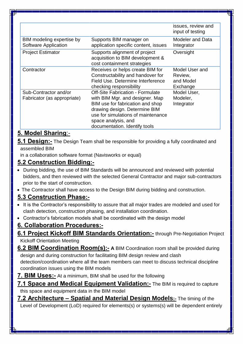
issues, review and input of testing
BIM modeling expertise by Software Application
Supports BIM manager on application specific content, issues
Modeler and Data Integrator
Project Estimator Supports alignment of project acquisition to BIM development & cost containment strategies
Oversight
Contractor Receives or helps create BIM for Constructability and handover for Field Use. Determine Interference checking responsibility
Model User and Review, and Model Exchange
Sub-Contractor and/or Fabricator (as appropriate)
Off-Site Fabrication - Formulate with BIM Mgr. and designer. Map BIM use for fabrication and shop drawing design. Determine BIM use for simulations of maintenance space analysis, and documentation. Identify tools
Model User, Modeler, Integrator
5. Model Sharing:-
5.1 Design:- The Design Team shall be responsible for providing a fully coordinated and
assembled BIM
in a collaboration software format (Navisworks or equal)
5.2 Construction Bidding:-
During bidding, the use of BIM Standards will be announced and reviewed with potential
bidders, and then reviewed with the selected General Contractor and major sub-contractors
prior to the start of construction.
The Contractor shall have access to the Design BIM during bidding and construction.
5.3 Construction Phase:-
It is the Contractor’s responsibility to assure that all major trades are modeled and used for
clash detection, construction phasing, and installation coordination.
Contractor’s fabrication models shall be coordinated with the design model
6. Collaboration Procedures:-
6.1 Project Kickoff BIM Standards Orientation:- through Pre-Negotiation Project
Kickoff Orientation Meeting
6.2 BIM Coordination Room(s):- A BIM Coordination room shall be provided during
design and during construction for facilitating BIM design review and clash
detection/coordination where all the team members can meet to discuss technical discipline
coordination issues using the BIM models
7. BIM Uses:- At a minimum, BIM shall be used for the following
7.1 Space and Medical Equipment Validation:- The BIM is required to capture
this space and equipment data in the BIM model
7.2 Architecture – Spatial and Material Design Models:- The timing of the
Level of Development (LoD) required for elements(s) or systems(s) will be dependent entirely

upon the project execution strategy used for the project, as the deliverables and their timing
will be different for DBB than for DB or IDP
7.3 Energy Analysis Energy simulation and life-cycle cost calculations shall be based on
information extracted directly from BIM and validated by energy modeling
7.4 Design Visualization for Communication, Functional Analysis, &
Constructability:-
BIM provides the opportunity to build a virtual building and to virtually test that building for
functionality during design.
This allows project stakeholders to see and understand design solutions that represents
reality so they can work towards improving the building design before construction starts
During design, special consideration must be given to medical staff and maintenance issues.
At
a minimum, BIM shall be used to validate:
● Nurses’ walking distances
● Nurse-station sightlines
● Process areas where timing and volume may be problematic (such as patient queuing
for waiting rooms and pharmacy, pharmacy delivery routes/timing
● Supply, Processing, & Distribution (SPD)
● Animations/graphics showing major building equipment and medical equipment space
clearance reservations for operations, repair, maintenance, replacement
● Color coding of floorplates for determining medical room/department locations and
square footages, and circulation
● Constructability
7.5 Building System Models – Structural, MEPF, 9 and Interiors
7.6 Masterplan Space Scheduling and Sequencing – 4D:- BIM 4D shall be used to illustrate the phasing plan
7.7 Communication of Construction Scheduling and Sequencing - 4D:- It is recommended that the Contractor also use BIM - 4D in schedule planning and
communication with the subcontractors and to understand the impact to the construction
schedule of other changes during the duration of the project
7.8 COBIE/Commissioning:- The Design/Construction Team shall consult their BIM software vendor(s) for the most current
COBIE utilities
7.9 Clash Detection/Coordination:-
Team’s responsibility to conduct and manage an adequate and thorough Clash Detection
process so that all major interferences between building components will have been
detected and resolved before construction
The BIM Manager shall assemble a composite model from all of the model parts of each
design discipline for the purpose of performing a visual check of the building design for
spatial and system coordination
On a multistory project, the models may need to be split on a level by level basis for
MEPF coordination

Coordination software shall be used for assembling the various design models to
electronically identify, collectively coordinate resolutions, and track and publish
interference reports between all disciplines
The team shall review the model and the Clash Reports in coordination meetings
the accuracy of fabrication models shall be verified
Design Consultants and Subcontractors who are responsible for multiple scopes of work
are expected to coordinate the clashes between those scopes prior
to providing those models to the BIM Manager for spatial and system coordination
Verification and tracking of resolved conflicts of all trade coordination issues
For ease of identification during the 3D Clash Detection/Coordination process, it is
recommended that the following trades be represented in these assigned colors:
Trade colors for Clash Detection
Architecture: White
Structural Steel: Maroon
Concrete: Gray
HVAC Equipment: Gold
HVAC Supply Duct/Diffuser: Blue
HVAC Return Duct/Diffuser: Magenta
HVAC Pipe: Gold
Electrical Equipment: Dark Yellow
Electrical Conduits: Light Yellow
Communication Conduit: Light Blue
Electrical Cable Tray: Dark Orange
Electrical Lighting: Yellow
Plumbing Water: Cyan
Plumbing Sewer: Magenta
Plumbing Storm Drain: Green
Fire Protection: Red
Pneumatic Tube: Dark Green
Equipment (Medical): Light Green
Medical Gas: Light Green
Security Systems: Orange
Fire Alarm: Fuchsia
7.10 Virtual Testing and Balancing:-

7.11 Additional BIM Uses:- ● Evaluating physical security & survivability
● Early MEP design
● 3D – Virtual functionality viewing and testing of the design
● 5D – Material take-offs & cost estimating
● Creating a interactive virtual workspace for the Design Team to achieve integrated design
goals
● Integrating information, e.g., electronic specifications that are tied to the BIM
● Achieving automated code checking
● Repeatable modular construction components to speed construction erection time
● Modular construction & off-site fabrication
8. 3-D Models, Formats, and Model Structures:-
8.1 General:- The BIM(s) shall consist of objects and elements that represent the actual dimensions of the
building elements and the building equipment that will be installed on the project. Before
modeling begins, the BIM Manager will work with the Design Team to develop the model and
model view extraction structure for all the construction document files to assure coordination
between disciplines
8.2 Subcontractor coordination:- the Contractor shall hold trade coordination meetings with subcontractors.
8.3 Digital Fabrication:- The following construction trades (at a minimum) shall provide 3D fabrication models with
parametric model objects:
Structural Steel Mechanical System Duct
MEP subcontractors (incorporate vendor models if available)
Curtain Wall Building Envelope Systems (rain screens, pre-cast panels, glazing systems)
Casework and furniture systems
Any additional fabrication models generated by subcontractor
9. Technology Platform and Software:-
9.1 Approved BIM Software for VA Projects:-

10. Modeling Requirements:-
10.2 Types of Model Elements:- a. Manufacturer’s Model Elements
b. Custom Created Model Elements
10.3 Model Geographical Location:-
The spatial coordination (coordinates) of the master BIM file shall be set at the beginning of
the project
10.4 Points of Reference The BIM Manager shall provide a 3D grid for incorporation into
the spatial coordination model. This will provide the viewer with a quick point of reference when
navigating through the model. Room information shall also be incorporated
10.5 Requirements for Modeling Space
a. Space information imported from the VA-SEPS-PFD Export shall be the source for space creation in BIM. 16 b. Areas of four square feet or greater shall be tracked and identified by name, even if those spaces are not listed in the VA-SEPS-PFD export. c. Spatial data shall be generated and associated with bounding elements (walls, doors, windows, floors, columns, ceilings).
d. The Net Square Footage (NSF) shall be modeled for each functional space in the PFD, using the appropriate space/object BIM tool to capture and carry the information
e. Space/area schedules and diagrams must be dynamically updated from the model geometry. f. VA PFD Spatial Requirements must be validated through reports generated from the BIM.
10.6 Meta Data:-
The BIM model(s) shall carry the following information:
a. Project ID – VA Construction Project Number
b. Station ID – VA Station Number
c. Project Name – VA Project Name

10.7 Space Naming and Coding:-
a. Building ID – VA Building Number
b. Wing
c. Floor
d. Department
e. Sub-department
f. Space Name – English Name & Abbreviation
g. Room Number – VA Wayfinding Room Number
h. Room Number – Construction Document Number (used on large complex projects for builder
use)
i. Space Code – VA-SEPS Room Code
j. Unique Space Number – GUID
k. Space Function - OmniClass 18
l. Space Type - Uniformat
m. Space Measurement - Net Square Footage (NSF), 19 Department Net Square Footage
(DNSF)
10.8 Medical and Mechanical Equipment, etc. Coding Each individual piece of
medical equipment and building mechanical equipment shall include the following attributes
a. Item Name – English Name & Abbreviation
b. Item Code - VA-SEPS Joint Services Number (JSN) 20
c. Unique Item Number - GUID
d. Item Function – OmniClass
e. Item Tracking Number – Category Stock Number (CSN) [for medical equipment]
f. Blank field for ECRI code or other (to come later)
g. Other data available from VA-SEPS that is accommodated by the COBIE 21 spreadsheet and
is appropriate to the LoD for the submission phase.
10.9 Final BIM Deliverables
3D Geometric Deliverables – Construction Coordination Model
The Contractor shall be responsible for providing VA consolidated as-built Model(s) for all
building systems. The Model(s) shall be fully coordinated and align with the Design Model for
architecture
and structure; the required instructions on file/folder setup shall also be included:
1. Contractor – Native file formats of the final consolidated as-built Model(s) for building
systems used in the multi-discipline coordination process (version as agreed in BIM
Management Plan)
2. Contractor – IFC file format of the consolidated building systems models (version as
agreed in BIM Management Plan)
3D Geometric Deliverables – Design Intent Model
The Design Team is to ensure that the “Design Intent model” remains current with all approved
bulletins for overall scope. It is NOT expected that product specific information will be added to
this model. Provide the Model information for architecture and structure and the required

instructions on file/folder setup:
1. Design Team - Native file format(s) of Design Model (version as agreed in BIM
Management Plan)
2. Design Team - IFC file format (version as agreed in BIM Management Plan)
Data Deliverables
1. Contractor – Provide COBIE database file containing room and product data information
described in previous sections of this document.
2. Design Team – Provide room/space data in COBIE format to be included in Contractor
COBIE database.
2D Deliverables
1. Contractor – Provide As-built drawings in PDF format with fully bookmarked pages.
2. Design Team – Produce one printed set of final documents generated from the Design
Intent Model
a. In PDF format with fully bookmarked pages.
b. DWG format (latest current version) with bound views to each sheet.
Digital Deliverables
All digital deliverables are to be submitted on DVD/CD with the data clearly organized and
software version(s) labeled.
11. Files, Security, Waivers:-
11.1 Project Folder Structure:-
a. BIM Folders
● Model Files
● Sheet Files
b. Support Files c. Coordination Files d. Other Folders
11.2 Data Security:-
Design Teams shall establish a data security protocol to prevent any possible data corruption,
virus “infections,” and data misuse or deliberate damage by their own employees or outside
sources. Both the Design Team and Construction teams shall establish adequate user access
rights to prevent data loss or damage during file exchange, maintenance, and archiving.
11.3 Waivers:- Situations could arise where adherence to this standard may be problematic. If such a situation
arises, the party creating the data must request a waiver. The VA is not opposed to such
requests, but the request must identify the specific standard for which the waiver is requested,
the
reason for the waiver, the resulting impacts on the use of the data for the purposes VA intends,
and any alternative approaches that should be considered. The VA Office of Construction and
Facilities Management will make every effort to resolve these requests in a timely manner.

12. Drawing Requirements for Paper Printing:-
12.1 General:- 2D CAD drawing information for the purposes of assembling a printed set of
plans shall be derived from the BIM model(s) to the fullest extent possible
12.2 Diffuser Symbols:- Either graphical arrows or blank-off panels may be used to represent air flow direction for
diffusers
12.3 Font:- Arial font typeface shall be used
12.4 Line Styles and Line Weights:- The internal software BIM Line Styles defaults
shall be used instead of the NCS and VA NCS Linetype definitions
12.5 MEP Details:- Where generating 2D MEP details from the model is difficult, tagged definitions of the object
based elements shall be provided.
12.6 Room Naming Abbreviations:- Room names on 2D drawing sheets shall be abbreviated for legibility.
12.7 Titleblocks:- The VA CAD Title Block and Information shall be adapted for BIM use by the Design Team.
12.8 Uniform Parameters for Objects:- The Object Element Matrix shall be used to assure that all model object parameters follow a
consistent naming convention and be a reflection of industry standards.
12.9 VA Standard Details:- The VA Standard Details are valid as to the information the details contain, and shall be used
for information regarding material and constructability content. In lieu of pulling the source
images directly into the model, the Design Team shall generate this information within the BIM
model allowing for object based recognition