VA BIM MANUAL V2.0 BIM - Whole Building Design Guide · PDF fileva bim standard november 10,...
39
BIM VA BIM MANUAL V2.0 NOVEMBER 2016 Rev 2/17
Transcript of VA BIM MANUAL V2.0 BIM - Whole Building Design Guide · PDF fileva bim standard november 10,...
BIMVA BIM MANUA
L V
2.0
NOVEMBER 2016 Rev 2/17

VA BIM STANDARD November 10, 2016 rev 2/17
BIM MANUAL i
Table of Contents 1. GENERAL INFORMATION ......................................................................................1
1.1. VA BUILDING INFORMATION LIFECYCLE VISION ............................................................. 1 1.2. LEGAL CONSIDERATIONS ................................................................................................. 3 1.3. REQUIRED DATA MANAGEMENT .................................................................................... 4 1.4. MODEL MANAGER RESPONSIBILITIES ............................................................................. 6
2. MODELING REQUIREMENTS .................................................................................6 2.1. GENERAL ......................................................................................................................... 7 2.2. OPEN DATA STANDARDS ................................................................................................. 7 2.3. BIM TECHNOLOGY AND PLATFORMS .............................................................................. 8 2.4. MODELING TOLERANCES AND DIMENSIONING .............................................................. 8 2.5. PROPERTIES AND ANNOTATIONS.................................................................................... 8 2.6. BIM OBJECTS ................................................................................................................... 9 2.7. LEGENDS AND SYMBOLS ............................................................................................... 10 2.8. SCHEDULES AND DETAILS .............................................................................................. 10 2.9. GEO-REFERENCE REQUIREMENTS ................................................................................. 10 2.10. QUALITY ASSURANCE/QUALITY CONTROL .................................................................... 10 2.11. MODEL PROPERTIES ...................................................................................................... 10 2.12. STARTING A NEW PROJECT (SEPS2BIM) ........................................................................ 11 2.13. MODELING SPACES ....................................................................................................... 11 2.14. MODELING ROOM CONTENTS EQUIPMENT (PRC) ........................................................ 13 2.15. MODELING SPACE RESERVATIONS ................................................................................ 15 2.16. MEDICAL TECHNOLOGY INFRASTRUCTURE................................................................... 15 2.17. ROOM TEST-FITS ........................................................................................................... 16 2.18. DISCIPLINE MODELS ...................................................................................................... 17
3. DELIVERABLES: BIDDING, CONSTRUCTION USE, AS-BUILTS, DATA ....................... 21 3.1. DRAWING DELIVERABLES REQUIREMENTS (DDR) COMPLIANCE .................................. 21 3.2. DESIGN-INTENT MODEL - BIDDING ............................................................................... 21 3.3. CONSTRUCTION AWARD ............................................................................................... 21 3.4. FACILITY MANAGEMENT DATA ..................................................................................... 22 3.5. FM MODEL .................................................................................................................... 22 3.6. GC AND AE CONSTRUCTION PERIOD SERVICES FOR FM ............................................... 22 3.7. CONSTRUCTION MODELS .............................................................................................. 24 3.8. AS-BUILT DRAWINGS ..................................................................................................... 24 3.9. DELIVERABLE SUMMARY ............................................................................................... 25
4. USING BIM ON A PROJECT .................................................................................. 26 4.1. EXISTING CONDITIONS .................................................................................................. 26 4.2. SITE MODELING ............................................................................................................. 26 4.3. DATA .............................................................................................................................. 27 4.4. EQUIPMENT MANAGEMENT ......................................................................................... 27 4.5. VERIFICATION, ANALYSIS, & DECISION SUPPORT ......................................................... 27 4.6. QUANTITY TAKE OFF ..................................................................................................... 31 4.7. SUSTAINABILITY & ENERGY ........................................................................................... 31 4.8. CONSTRUCTABILITY AND SYSTEMS COORDINATION .................................................... 31 4.9. COMMISSIONING AND HANDOVER .............................................................................. 33 4.10. USE OF NEW TECHNOLOGY/TECHNIQUES .................................................................... 33
5. DEFINITIONS ...................................................................................................... 35 6. ACKNOWLEDGEMENTS ...................................................................................... 37

VA BIM STANDARD November 10, 2016 rev 2/17
BIM MANUAL 1
1. GENERAL INFORMATION
1.1. VA BUILDING INFORMATION LIFECYCLE VISION
1.1.1. Purpose The United States Department of Veterans Affairs (VA) is committed to utilizing Building Information Modeling (BIM)1 tools, 3D Models, 2D Drawings, Data, and other uses to support the delivery and management of world-class healthcare for our nation’s veterans. The goal of VA’s use of BIM for new facilities is to deliver higher value in quality, timeliness, cost, and to maximize building performance during operations. VA recognizes BIM is not a specific software platform but rather an innovative process that encompasses the use of various software and techniques. VA has adopted the BIM definition provided in the National BIM Standard:
“BIM is a digital representation of physical and functional characteristics of a facility. BIM is a shared knowledge resource for information about a facility forming a reliable basis for decisions during its lifecycle; defined as existing from earliest conception to demolition.2”
BIM represents a paradigm shift in the product, management, and delivery of planning, design, construction, activations, facilities operations, and real managing of property that if utilized properly, promises to deliver significant value for owners. Just as digital medical records help VA improve patient care, so standardized building data available electronically across VA will help the agency take advantage of previously inaccessible knowledge to manage its real property portfolio lifecycle more efficiently.
BIM and other digital tools can enhance communication and Lean efficiencies during project development, providing all stakeholders an improved way of understanding the issues so they can fully participate together in solving problems. Because of these advantages, VA adopted BIM for design on Major Construction projects in 2009 and issued the BIM Guide requirements for use on all VA construction in 2010, but as technology and business practices enabled by BIM have been continuously evolving, revisions were necessary. This release of VA BIM Standard, a collection of documents which includes this BIM Manual, will allow VA and our industry partners to apply the efficiencies BIM provides to capital asset projects for VA.
VA will utilize BIM to provide stakeholders with a greater understanding of how a building is to be planned, designed, constructed, used, operated, and managed. BIM will serve as a virtual representation of the actual building, and the basis of the 2D documentation (i.e., plans, elevations, sections, schedules, 3D perspectives, isometrics, and details), which are generated from and must be fully coordinated with the concurrent model.
Industry has used BIM tools to enable Lean business process improvements that have made dramatic advances in eliminating wasteful, non-value added effort in design and construction workflow. The result has improved project coordination, reduced rework, and accelerated
1 BIM is used both a verb (modeling) and a noun (model) in industry 2 National BIM Standard v1 2007

VA BIM STANDARD November 10, 2016 rev 2/17
BIM MANUAL 2
project delivery. VA requires all Architect-Engineer (AE) and General Contractor (GC) Teams to drive inefficiencies out of their workflow by employing Lean/BIM methodologies to increase delivery efficiencies in relation to faster delivery, and increased quality of design and construction.
1.1.2. VA Objectives for BIM use A. IMPROVE ACCESS TO HEALTHCARE for veterans by reducing the time it takes to deliver
a high-performing facility through the use of more efficient and Lean business processes enabled by BIM.
B. EXECUTE A FACILITY INFORMATION LIFECYCLE APPROACH for healthcare buildings through the use of digital information developed and shared through the activities of facility planning, design, construction, activations, facility management, portfolio management and property disposal, to help achieve better stewardship of VA’s capital assets.
C. VALIDATE THAT THE PROPOSED DESIGN SOLUTION solves VA’s medical functional needs, regulatory requirements, building operational needs, and safety requirements.
D. ACHIEVE IMPROVEMENTS IN CONSTRUCTION by recognizing that the AE’s work deliverable must be tailored specifically for the needs of contractors; consequently VA intends to use the models (not just the drawings) for construction purposes such as the use of regular 3D coordination meetings during design and construction (to reduce field coordination issues such as Requests-For-Information (RFIs) and change orders), general quantity take-offs for materials, using survey coordinates for the site and building layouts, and other process improvements such as off-site fabrication, etc.
E. ENHANCE COMMUNICATION AND FEEDBACK through the use of live, facilitated reviews with all stakeholders (i.e., VA leadership, medical staff, construction trades, facilities staff, etc.).
1.1.3. Requirements for Implementation VA BIM Standard applies in entirety to the physical asset documentation of existing and new healthcare facilities owned by VA. These standards apply to all design and construction projects where the services of a professional licensed architect or engineer (AE) are required to sign the construction documents and to other work if the final deliverable is ultimately to be used to document the physical asset, even in cases where a licensed professional is not required. VA BIM Standard applies to the work of the AE and the construction team managed by the General Contractor (GC). The use of BIM on non-recurring maintenance (NRM) projects is encouraged but is at the discretion of the local VA facility.
Design documentation and submittal requirements for properties leased by VA: Refer to VA’s Lease Solicitation for Offerors.
1.1.4. VA BIM Standard Documents • VA BIM Manual v2.0
Appendix 1 - Room Data Sheet Example Appendix 2 – Maintaining Coding for 2D PRC Appendix 3 - VA Spatial & Equipment Data
VA BIM STANDARD November 10, 2016 rev 2/17
BIM MANUAL 3
Appendix 4 - Interior Partitions, Fire-Rated Partitions & Smoke Barriers Appendix 5 – Instructions for Geo-Referencing
• VA Drawing Deliverable Requirements (DDR) v1.0 Appendix A – VA Sheet Identification Appendix B – VA Sheet Example Appendix C - VA BIM/CAD Folder and Filing Structure
• Drawing Sheet Templates VA 30x42 Sheet – Revit Family file VA 30x42 Sheet – .DWG file VA Shared Parameters – Revit Text file
• VA FM Data (Data requirements for Facility Management)
Archived Documents for working with Legacy CAD Files: VA Legacy Layer List VA NCS CTB Table
Other relevant reference documents include (but aren’t limited to): • PG-18-15 Vol. B and Vol. C (VA Design Submissions) • VA Facility Space Measurement Standards • SEPS2BIM
1.2. LEGAL CONSIDERATIONS
1.2.1. Ownership and Use of BIM The ability to own, reuse, and properly manage building data throughout the facility lifecycle accrues significant advantages for an owner. Consequently, VA places significant importance on the accurate creation, management, and stewardship of all digital information (including but not limited to Models, 2D Drawings, specifications, visualizations, and data) created during project development and execution. VA intends that this information will be used for planning, design, construction, equipment selection, facility management, as well as other purposes (including but not limited to commissioning, management of project activities, and real property reporting), and by other software as needed.
In accordance with FAR Part 27, clauses incorporated in Section 00 72 00, Contract Clauses and Special Contract Requirement 1.14 GOVERNMENT RE-USE OF DESIGN (Section 00 73 00), the Government has ownership of and rights to all CAD files, BIM Models, objects, elements, associated model data, and Facility/Site information, etc., developed under contract to the government. The Government may make use of this data for any purpose. Model elements that pre-exist the contract, and that are incorporated into the BIM, are perpetually licensed to the Government, without fee, for use in constructing, operating, maintaining, renovating, and expanding the facility. Neither the AE, nor the GC will assert against the Government any right of copyright to materials developed under contract to the Government.
1.2.2. Contract Documents The Design-Intent Model is the AE’s primary design deliverable to VA. The 2D drawings are derived from the Design-Intent Model, but only reflect specific extracted views, and do not contain as much information as is in the Model, itself. The General Contractor is required to construct in accordance with the Model, as amended through contract approved processes. The
VA BIM STANDARD November 10, 2016 rev 2/17
BIM MANUAL 4
Contract Documents may specifically state for construction costs less than $20 million that 2D drawings or other information takes precedence over the Design-Intent Model, but in all other cases, the Design-Intent Model takes precedence over the 2D drawings, and the non-editable federated Design-Intent Model will be the Instrument of the Contract used for construction award (NWD or equal). Regardless, all revisions to the Contract Documents after construction award must be made in the Design-Intent Model and the subsequent updated 2D Drawings must be derived from the updated Model. All models must be shared with project stakeholders as needed.
1.2.3. Authority of a Federal Construction Agent On those projects where VA is using the services of a Federal agency with construction authority to act as the Construction Agent, such as the United States Army Corps of Engineers (USACE), Naval Facilities Engineering Command (NAVFAC), or General Services Administration (GSA), the Construction Agent will use VA BIM Standard to manage the work. If a Construction Agent is used, the Construction Agent will exercise the rights of VA to manage the work required in these documents. Exceptions are where deviations from VA Standards are requested, approvals needed by users, or in other cases where noted.
1.2.4. Reviews, Approvals, Issue Resolution, and Waivers Situations may arise where adherence to this standard is not in the best interest of VA. If such a situation arises, the party creating the information must request and obtain a waiver from VA before deviating from VA BIM Standard. If a Construction Agent is used the Construction Agent must submit the waiver request to VA for a decision. The Construction Agent is not authorized to waive VA BIM Standard. VA is not opposed to waiver requests, but the request must identify the specific standard for which the waiver is requested, the reason for the waiver, the resulting impacts on the purposes VA intends, and any alternative approaches that should be considered. The AE and the GC must update their respective BIM Project Execution Plans (PxP) with any approved waivers.
1.2.5. Required Expertise All work requiring services to create BIM Models and data about or for VA facilities must take place under the formal direction of a BIM professional who has a minimum of five years of proven experience in using BIM for similar projects of size and complexity, and who can provide examples of competency to execute the requirements in VA BIM Standards. Design services must be conducted under the supervision of a licensed professional architect and/or engineer. Site surveying, identifying the survey monument for the project, laser or photogrammetry scanning, must be under the formal direction of a licensed professional surveyor competent in geomatics.
1.3. REQUIRED DATA MANAGEMENT
1.3.1. Importance of Data Integrity in Building Lifecycle VA considers building data to be a strategic asset that must be managed appropriately to maintain its value. All entities working on VA capital asset projects will take due care that data nomenclature, integrity, accuracy, and completeness are maintained during project delivery and transfer between software applications.
VA BIM STANDARD November 10, 2016 rev 2/17
BIM MANUAL 5
VA will be using the COBie3 format as the method to import information into IBM® Maximo® Asset Management system, VA’s CMMS4.
1.3.2. Folder and File Structure All deliverables will be appropriately named and stored as described within VA BIM Standard - Drawing Deliverable Requirements (DDR).
1.3.3. BIM Project Execution Plan (PxP)5 The PxP is a process management document executed between the AE prime and its consultants, and between the GC and its sub-contractors, which defines how those teams will use BIM to meet VA requirements. The PxP must include the standards, responsibilities, and protocols for modeling and file transfers (such as setting up collaboration servers). The AE and GC’s PxP(s) will be used to track progress towards meeting VA BIM requirements.
The AE, with the assistance from VA, will assist in the transition between the design and construction PxP in Design-Bid-Build (DBB) procurements. The AE PxP must be used as the basis for the GC PxP, and will be updated as required by the GC.
The protocol for sharing the models between the AE and GC, and the method of coordination during Construction Period Services for the handoff of information, including scheduling handoff dates, formatting, responsibilities, data validation, etc., must be coordinated between the AE and GC and documented in their respective PxP plans.6
The AE must submit the PxP according to the PG 18-15 list of deliverables. The GC must submit their PxP with the required overall Project Management Plan submittals and resubmit the PxP periodically again at construction milestones and when updated.
The PxP(s) must include a Project Data Security Plan for the exchange of information during design and construction and a COBie Execution Plan for managing VA FM Data. The Data Security Plan must address the methods and systems for protecting and managing the data developed under contract with VA to prevent unwanted intrusion, viruses, damage, and unauthorized access to project files and to assure that data is effectively backed-up and secured. It is the responsibility of the AE and GC to ensure that digital systems, software, and servers, etc. being used to create or manage VA building information during project delivery are accessible to only those individuals who are responsible for design, construction, coordination, management, and/or approval of the specific project.
The PxP(s) must provide the information as required in the Army Corps of Engineers (USACE) PxP Template.
3 Construction Operations Building Information Exchange (COBie) 4 Computer Maintenance Management System (CMMS) 5 Also known in industry as the BIM Execution Plan (BxP) 6 For additional information on PxP, see the National BIM Standard – United States® (NBIMS-USTM).
VA BIM STANDARD November 10, 2016 rev 2/17
BIM MANUAL 6
1.4. MODEL MANAGER RESPONSIBILITIES One individual must be designated as the Model Manager to be the responsible person who is accountable to VA for BIM, including data creation and model management coordination between team members for the project. If the project is being procured by Design-Bid-Build then there will be a separate Model Manager for the AE and the GC who must coordinate their respective work. If Design-Build (or other similar joint Design/Construction entity) procurement is used, there may be just one Model Manager for the entire project work.
Each Model Manager is accountable to VA for the following activities:
• Ensuring compliance with VA BIM Standard and required deliverables
• Developing, maintaining, updating, distributing, and providing clarifications to/for the PxP
• Structuring, defining, coordinating, and managing model creation, model and data quality control across all firms, disciplines, or trades under its contractual umbrella
• Leading and facilitating the BIM Management Project Kick-off meeting with project team member modelers to explain the BIM project objectives and management protocols
• Verifying that the geo-references in the associated technical discipline models are properly referenced to the identified project permanent survey monument and with each other
• Ensuring regularly scheduled periodic Design Coordination and/or Construction Coordination review meetings
• Coordinating updates of the Design-Intent model(s) to create the FM Model and delivery of BIM-derived 2D Drawings and other information as required to support the project delivery process
• Instituting Quality Control (QC) for proper modeling, standards adherence, and classification of all spaces and equipment as required
• Providing proper delivery and data and model quality control and coordination with VA Activations/VA Medical Center Engineering for the transfer of VA required facilities management data and BIM to Maximo
• Transferring (responsibility of AE) the required information to Maximo and performing operational testing in Maximo to assure it functions properly
2. MODELING REQUIREMENTS KEEPING THE END IN MIND7 - The Models, 2D Drawings, and specifications serve three essential purposes: First, the information must effectively and clearly convey the AE’s design to allow VA to evaluate the suitability of the design for VA’s operational needs; Second, the information must unambiguously present the design to the GC and its subcontractors and vendors during the bidding and construction process, thus minimizing RFIs and eliminating Change Orders due to incomplete, inaccurate or conflicting information (VA expects that AE documentation will correspond to the contractor’s need
7 Quote by Stephen R. Covey

VA BIM STANDARD November 10, 2016 rev 2/17
BIM MANUAL 7
for information and to support efficient project execution); Third, the information must support VA’s Facility Management requirements.
The information listed in this section is a minimum requirement. It remains the responsibility of the AE and the GC to create the appropriate level of information needed to fulfill their required contractual project obligations. It is expected by VA that the models, analyses, and data will be used to support the decision making process for high performance building design and construction activities.8
2.1. GENERAL At a minimum, all elements within the scope of work and within the limits of the construction site or that may be affected by construction must be modeled, including but not limited to:
• All building structures, equipment, and systems
• Utilities above or below ground inside and outside of project boundaries to service connection points
• Construction Details
• All major vegetation (e.g., heritage trees) to be preserved
• Any areas to be protected during construction
• Project site conditions
• Equipment needed for Room Test-fits
2.2. OPEN DATA STANDARDS VA is committed to the interoperability of data as a strategic management tool to enable access and reuse of building information over the lifecycle of its capital assets regardless of software used. The models and data must be developed using national standards so that information can be machine read and used throughout the facility lifecycle that will occur over a great number of years. Unique GUIDs9, assigned in the Space and Equipment Planning Tool (SEPS) or in the BIM tools, must be maintained throughout project development and delivery to support data workflows that require keeping track of space and equipment.
Users should consult with their BIM-authoring application vendor to learn the recommended method for creating space objects that can be exported to an IFC format.
8 Note: Refer to the General Services Administration’s BIM Guide 07 for an excellent description of modeling and coordination meetings. 9 GUID – Globally Unique Identifier, which is a unique code identifying each object/space. A GUID should not be confused with “code” in “room code,” “equipment code (JSN),” or “space code.” The GUID assigned by the BIM authoring tool persists through room name changes and various other modifications, allowing the object/space to be tracked throughout the project execution process.

VA BIM STANDARD November 10, 2016 rev 2/17
BIM MANUAL 8
2.3. BIM TECHNOLOGY AND PLATFORMS VA is vender neutral in regards to the use of specific authoring software platforms, and accepts parametric software applications that comply with current Industry Foundation Classes (IFC) standards (ISO 16739) as the structure for future-proofing access to legacy projects and for exchanging building data. All IFC model deliverables must be derived from native software authoring tools. If, for some specific purpose a specific platform must be used for design that diverges from these requirements (such as at the request of VA Chief Engineer at a Medical Center), an approval via waiver will be obtained from VA and noted in the PxP. BIM software authoring platforms used for documentation of VA capital asset projects MUST be:
• Certified to meet the most current Industry Foundation Classes (IFC) Coordination View and FM Handover View (COBie).
• Within one version of the current authoring software release at project turnover. This is to ensure that the Model is viable for facility management.
2.4. MODELING TOLERANCES AND DIMENSIONING Building Objects/elements must to be modeled in their exact location within the industry standard tolerance for the trade or discipline being represented, but in no case greater than 1/8”. All BIM Objects for construction must be modeled to actual real-world dimensions (not nominal). The AE and GC are responsible for designating stricter tolerances if needed to facilitate the intended uses of the model as outlined in this manual or as needed to execute the project. GC modeling for construction uses must have tolerances that enable accurate manufacture or layout of elements to which it applies. If laser-guided layouts (such as Total Station), pre-fabrication, or modular assembly techniques are being used, then the modeling teams, preferably with the GC, will review the tolerances required in those areas and for that building system component. Results and any adjustments affecting current and future modeling must be documented in the PxPs. Exceptions must be approved by VA and also noted in the PxP.
Dimensions must comply with the DDR10. Dimensions must be automated, object referenced and associated, and must not be overridden. Dimensional values (i.e., the text appearing in dimension strings) will be in Imperial units (e.g., 10’-0”).
2.5. PROPERTIES AND ANNOTATIONS The BIM Model(s) and BIM Objects must contain the appropriate non-graphical properties to accurately support automatic population of annotation tags and schedules from within the BIM software. In general, all information that would appear in a schedule for a particular object must have object properties with populated values.
All general annotations must comply with the DDR. Where VA BIM Standard does not explicitly define a standard for a particular type of annotation, the latest version of the National CAD Standard applies. The models must be documented with the appropriate tool within the BIM software designed for that purpose.
10 Refer to the National CAD Standard BIM Implementation Section.

VA BIM STANDARD November 10, 2016 rev 2/17
BIM MANUAL 9
All references including but not limited to elevations (interior or exterior, partial or whole), sections (building, wall, or object), plan, and detail callouts or marks must be created using the appropriate tools/commands from within the BIM software and remain dynamically connected throughout the project. Manual overrides are not permitted.
Titleblock identification values (e.g., sheet number and sheet name) must be associated and automatically populated and remain current throughout the project.
Annotation symbols such as tags are to read and display information contained within the model properties. Fire rating fill patterns must be constructed within 3D wall types so that the partition’s respective rating is shown through all scales and types of views, including 2D Drawings.
2.6. BIM OBJECTS The term BIM Objects encompasses elements, components, and systems. While the terminology is often interchanged and the understanding can vary based on software platform used or VArious disciplines/trade involved, the basic concept is that BIM Objects refers to an individual item, or a collection of items, that comprise the model(s) for the design of the facility and the site. All BIM Objects and categories must be named in accordance with VA FM Data Spreadsheet 11 and space & equipment standards12. Where no VA naming is available, follow a logical naming convention that is to be documented in the PxP.
The authoring of BIM Objects must adhere to the following guidelines:
• Global Properties must be used where appropriate to increase modeling value and performance. The attribute of any given BIM Object will reference global properties for its respective category. For example, a Width property for one piece of equipment must use the same global properties designated as Width for all equipment within the same category. Additional properties denoting the same attribute with slight variations must not be created (i.e., width1, Object Width, etc.)
• All objects must be modeled or created using the tool within the software that is designed to be used for that specific object or purpose. For example, a BIM software’s wall tool must be used to create a wall. A wall is not permitted to be merely drafted lines. If a new object is created then it must be designated as the real world element it represents, having the proper classification and/or data attributes for the project and object type, and must report properly from the BIM software as the objects they represent rather than unassigned graphic primitives. This will allow the information associated with them to be properly updated, reported and available for export and reuse. Generic, miscellaneous, or unspecified categories are not allowed.
• Use BIM authoring software object libraries13 when creating BIM Objects whether they are actual 3D BIM Objects or 2D representations. Models must be comprised of the software’s BIM Objects for representing building products. Geometric lines, arcs, and vertices are not allowed.
11 Facility Management (FM) Data 12 Appendix 3 - VA Spatial & Equipment Data Spreadsheet 13 Revit: Annotation Families; Detail Component Families

VA BIM STANDARD November 10, 2016 rev 2/17
BIM MANUAL 10
This is necessary to enable classification and reference keynoting (such as the Unified Facilities Guide Specification (UFGS) or MASTERSPEC number).
2.7. LEGENDS AND SYMBOLS Legends and symbols in the 2D drawings may be 2D representations but are to be connected to the actual BIM Objects to which they are referring (i.e., any change to the actual BIM Object will result in an immediate updated 2D representation). Actual BIM Objects must be 3D objects with attached or associated data and metadata as defined throughout VA BIM Standard.
2.8. SCHEDULES AND DETAILS All construction details must be “Model Details” and created with BIM tools and linked to the 3D view. All details that appear on 2D Drawings must be derived from BIM and match the assembly in BIM. No “Drafting Details” created in 2D software and added to the 2D Drawings will be accepted.
All 2D drawing schedules must be derived from the properties of the model object, with the exception of calculations (e.g., calculations for low voltage, structural, electrical, etc.). Schedules are not to be augmented with unconnected data. Exceptions where calculations are done outside of BIM must be noted in QA/QC reports and state the technical reason for the exception.
2.9. GEO-REFERENCE REQUIREMENTS VA requires that all models contain geospatial information that is properly referenced between a permanent, physical, USGS14 Survey Marker’s geographic survey point (Site Origin Point) available in the State Plane Coordinate system where the project is located, and the coordinate system in the model space (Project Base Point15), thereby providing a precise, measurable reference point for accurately locating and constructing buildings, site work, utilities, and infrastructure. (See Appendix 5 – Instructions for Geo-Referencing)
2.10. QUALITY ASSURANCE/QUALITY CONTROL The AE and the GC are responsible for assuring their models and data submittals have been thoroughly checked and meet VA BIM Standard and contract requirements for the project. Models and data must be submitted as noted in Section 3.9 – Deliverable Summary, for compliance evaluation by VA.
2.11. MODEL PROPERTIES Physical construction and products that are represented in objects must include the basis of design for the properties of the object as described in VA FM Data Spreadsheet and the Appendix 3 - VA Spatial & Equipment Data Spreadsheet. The AE may use external BIM tools to manage the data during design if the external tools are IFC compliant. The final deliverable must provide the required information in a COBie format for import into Maximo. (There is a COBie import feature available in CORE Maximo for the data and a viewer API for the 3D Model.)
14 United States Geological Survey = USGS 15 Base Point, Survey Point, and Origin Point are names for the same thing in different software systems

VA BIM STANDARD November 10, 2016 rev 2/17
BIM MANUAL 11
The AE will model all BIM Objects with sufficient detail necessary to communicate design intent (if Design-Bid-Build procurement) for construction, conduct design coordination, and facilitate VA BIM requirements. If a Design/Build procurement will be used, the AE must model for construction fabrication and adapt that model for FM (see FM Model).
The GC will model detailed elements of building equipment and systems, with their accompanying space reservations as defined in VA BIM Standard, and for other uses as determined by the GC.
OmniClass Codes16 (latest published version) must be assigned to all spaces, building equipment, systems, and underground utilities. Spatial Objects must maintain the codes provided in the SEPS BIM Export file. If a new Space Object has been created or does not have an OmniClass code in the PFD, then the appropriate OmniClass code must be applied. Use OmniClass Tables 13 and 14 in combination as appropriate for spaces and OmniClass Tables 21, 22, and 23 for building assets: Table 21 for systems, Table 22 to align modeled technical solutions with specification sections, and Table 23 for building equipment.
2.12. STARTING A NEW PROJECT (SEPS2BIM) At the beginning of the design work for each new project, VA will provide a Project BIM Export file from SEPS in an Excel spreadsheet format to the AE. This file will include 1) the Program for Design (PFD) which lists each required room and the amount of space the room contains, and 2) the Project Room Contents (PRC) which provides a preliminary equipment list for each room. The PRC will be further refined by the AE Equipment Planner for the specific project. The final deliverable, called the Room Contents List, will identify the equipment in each room for VA Activations use. The Project BIM Export file must be used as the source for creating the room layouts in BIM and establishing a starting point for refining the non-medical and the medical equipment contents for each room. The Project BIM Export file contains the unique identifying GUID codes (and other data) so that the rooms and equipment can be tracked throughout the project development. The AE and GC must maintain the naming, GUIDs, and other codes and identifiers in the Project BIM Export file as required and include them in work deliverables provided to VA (See Appendix 3 - VA Spatial & Equipment Data, and VA FM Data). The SEPS Project BIM Export file, containing the naming and GUIDs for the PFD and PRC information, must be directly imported into BIM architectural plans and equipment objects or associated software.
At the AE’s discretion (but highly recommended), free add-ins (SEPS Space and Equipment Aggregator, SEPS Department Aggregator) which facilitate downloading the files into various software17 are available from SEPS2BIM.org; however, if SEPS2BIM is not used, the AE must assure VA that all the codes derived from SEPS are accurately maintained for the required spaces and Objects. (SEPS2BIM training)
2.13. MODELING SPACES
2.13.1. Spatial Objects Spatial Objects are defined as rooms, departments, and areas, and mechanical objects such as spaces and zones that are typically a part of the Architectural, MEPFT, and Interior Design
16 For questions about OmniClass, consult the Construction Specifications Institute (CSI). 17 Revit, Onuma, SketchUp, & Attainia currently can import data using SEPS2BIM

VA BIM STANDARD November 10, 2016 rev 2/17
BIM MANUAL 12
models. All Spatial Objects must be generated with the appropriate BIM tool and associated with bounding elements (walls, doors, windows, floors, columns, ceilings). All properties information associated with Spatial Objects appearing in schedules, VA FM Data Spreadsheet and VA Spatial & Equipment Data exports, tags, and diagrams, etc., must be fully generated from and connected to the model geometry which defines its boundaries.
2.13.2. Spatial Data Spatial Data is defined as the properties of each Spatial Object, and applies to areas of four square feet or greater, even if those spaces are not listed in the SEPS PFD. Design progress submissions (described in PG 18-15) must contain a tabular calculated comparison of the current proposed project design square footage measurements derived from BIM against the approved project PFD square footages derived from SEPS. Coding noted in Appendix 3 - VA Spatial & Equipment Data from the SEPS BIM Export file must be maintained with the Spatial Object throughout project development so that the specific space object can be tracked.
2.13.3. Modeling Space Rooms: The Net Square Footage (NSF) must be modeled for each functional room and space. Rooms must be represented and broken down into functional areas (e.g., Medical Exam Room, Laser Treatment Room, Waiting Room, etc.) as defined in the PFD even though they may be parts of a larger designed physical area. A physical area may contain several functional areas that are treated as individual rooms in the PFD spatial program. If two rooms have different functional space classifications, even though they are within the same physical area, they must be modeled as two separate spaces. For example, a security checkpoint area within a lobby that is not enclosed by walls must be defined as two separate non-overlapping spaces. These spaces might also be grouped into a Zone, for visualization and analysis purposes (e.g. for thermal simulation calculations). The PFD NSF and the proposed design NSF must be shown on all 2D plans in each room and space.
AEs should consult with their BIM authoring application vendor to learn the recommended method for measuring room square footages.
Departments: The VA Medical Center will define the organizational arrangement for providing services. Rooms must be grouped into the Medical Center defined Departments for space management and square footage analysis, and color coded to help distinguish space belonging to the different organizations.
Circulation Factors: Must be calculated based on the spatial values derived from the floorplates in BIM.
2.13.4. Measuring Space Refer to VA Standards Alert18 002a Standardization of Square Footage Space Definitions and Measurement for VA Facilities for guidance on definitions and on how to measure spaces.
18 Located in the VA Technical Information Library

VA BIM STANDARD November 10, 2016 rev 2/17
BIM MANUAL 13
2.14. MODELING ROOM CONTENTS EQUIPMENT (PRC) The Project Room Contents (PRC) exported from SEPS provides a preliminary room contents list. Because room contents in a hospital setting are categorized by type, purchasing, utility requirements, coordination with the GC, etc., room contents require a complicated taxonomy and definitions to understand how to model, organize, track, and manage the information through the planning, design, construction, procurement, and activation processes. PRC equipment must carry the appropriate properties as outlined in the VA FM Data Spreadsheet and VA Spatial & Equipment Data requirements.
2.14.1. Acquisition Codes The responsibilities for PRC equipment purchasing and installation are defined by a VA Acquisition Code that is designated for each piece of equipment. All room contents must have Acquisition Codes associated with the equipment object.
The codes are:
• VV = Government Furnished/ Government Installed
• VC = Government Furnished/ Contractor Installed
• CC = Contractor Furnished/Contractor Installed
• R = Reused Existing Equipment
2.14.2. Medical Equipment Definition Fixed or movable specialized equipment that is used for the treatment of patients.
2.14.3. Food Service, Laboratory Equipment Definition Specialized non-medical equipment used for preparing, storing, and transferring food, or equipment needed to conduct laboratory experiments.
2.14.4. ASE Equipment Design and Construction Coordination Medical Equipment, Food Service, and Laboratory Equipment, and other equipment that requires construction coordination for structural support or utility hookups is considered Architecturally Significant Equipment (ASE)19 and must be carefully managed and coordinated.
ASE is medical and non-medical equipment items that are customarily installed by the manufacturer or vendor that can impact the construction critical path schedule and/or requires connection to/accommodation by building infrastructure. Close coordination between VA Activations/procurement, equipment planners, General Contractor (GC), installer/vendor, and AE, is required.
ASE includes surgical lights and booms, fume hoods, sterilizers, imaging equipment, radiotherapy equipment, ceiling mounted patient lifting devices, patient headwalls, walk-in refrigerators, kitchen equipment, laundry, computer servers, etc.
19 The Facilities Guidelines Institute uses the term Major Technical Equipment instead of ASE.

VA BIM STANDARD November 10, 2016 rev 2/17
BIM MANUAL 14
ASE is generally purchased by VA with Activation funds, as these items are not typically part of the construction contract (Acquisition Codes VV, VC).
All ASE must be identified as “ASE” in the equipment object properties, which also must include all information and modeling needed for equipment required utility hookup components, shielding, structural support requirements, etc., up to the connection point to the building systems. ASE equipment and rooms must also be labeled in BIM and on the 2D room layouts.
2.14.5. Furniture, Fixtures, and Equipment (FFE) FFE is defined as Furniture (e.g., modular furniture, office furniture, furnishings, etc.), Fixtures (coat racks, white boards, signs, etc.,) and Equipment (computers, telephones, etc.). FFE that is fixed (e.g., built-in casework) and purchased as a part of the construction contract (Acquisition Code CC) must be placed in the Architectural model or the Interiors model that is referenced to the Architectural model file.
2.14.6. PRC Equipment Objects Equipment that is to be purchased by VA (Acquisition Code VV, VC) must be modeled without complex detail to LOD 30020 but accurate to size for test-fitting, so that model efficiency will not be impacted. The final equipment selection will be determined during the construction phase of the project.
Equipment purchased through the construction contract (Acquisition Code CC) must be appropriately modeled for fabrication (e.g., casework) or for adequate mechanical room test-fitting (e.g., boilers, generators). When modeling, do not attach FFE equipment objects to a surface, because the ability to replace the initial (design-intent) objects with the actual objects after final selection will be compromised.
Single instances of rooms must have 3D PRC equipment objects (LOD 300) placed in each room for Room Test-Fitting. Where there are multiple instances of the same room with the same PRC or building equipment and the PRC utility connections to the building have standardized room locations, there must be one standardized room which contains 3D equipment objects; duplicate spaces may show the equipment as 2D objects in the plans, elevations, etc. Assure all 2D objects are intelligent for classification/keynoting. (See Appendix 2 – Maintaining Coding for PRC)
2.14.7. Room Contents List (and Data) Working with the Medical Center user groups, the AE Equipment Planners will refine the SEPS Project Room Contents List into a Room Contents List which will be used by VA Activations to select the make, model, features, and manufacturer during the construction phase. The Room Contents List deliverable will be provided as an Excel file (.xlsx) or other format as approved by VA, and must include the individual equipment item names, location (e.g., SEPS Room Code,
20 For more information and definitions of LOD, consult the latest version of BIMForum Level of Development Specification
VA BIM STANDARD November 10, 2016 rev 2/17
BIM MANUAL 15
Room GUID, Project Room Number, and English Name), JSN21, required data codes, VA Acquisition Codes, utility codes, etc., for the equipment located in each room as provided in the original SEPS BIM Export file and the ASE designation (if applicable). This coding must be maintained or linked with the PRC Equipment Object throughout project development and execution so that the equipment or system can be tracked between its location in BIM and the Room Contents List. Equipment with Acquisition Code R (which is not in SEPS) must have similar coding created by the AE for tracking. (See Appendix 3 - VA Spatial & Equipment Data)
2.14.8. Model Referencing All discipline models must reference each other, and the references described in the PxP, to assure proper coordination (utility hookups, shielding, structural support, etc.) between disciplines.
2.15. MODELING SPACE RESERVATIONS The AE and the GC must model space reservations (clearance or no-fly zones) for access to MEPFT building equipment and distribution systems, and for coordinating the locations for, and access to, systems that are installed after major building systems are put in place, such as medical technology (low-voltage), business systems, and fire protection systems. Space reservations must be included in all Design and Construction Coordination management activities, and be labeled by discipline, color coded, and designated NIC22 (when applicable) in the Model and plans. All space reservations must accommodate operations, adequate physical and tool/tool cart access (including unobstructed paths of travel) for repair, maintenance, and replacement, including major equipment removal, equipment replacement pathways to access hatches, knockout panels, doors, and hoists, and access to equipment, systems, and attachments located above ceilings. Space accessibility reservations must incorporate code requirements, manufacturer’s maintenance zones, equipment specifications, and any owner-specific design requirements.
Space reservation zones must be modeled with 3D (volumetric) shapes; the transparency must be between 65% and 85%. During Design Coordination space reservations must be based on the maximum anticipated size of the equipment; model routing reservations for Acquisition Codes VV, VC accordingly. The GC’s Construction Coordination space reservation settings must be based on the actual access requirements of the system or equipment selected or managed (e.g., Fire Protection) by the GC for installation. The GC must confirm with VA the routing and sizes needed for medical technology, business systems, etc., and assure that the space reservations for those systems are not encroached. VA will approve the final routing and space reservations; the GC must install the building systems to the approved Construction Coordination locations. (See Section 4.8.1)
2.16. MEDICAL TECHNOLOGY INFRASTRUCTURE Medical technology systems are purchased by VA and generally installed after major building systems. In order to ensure that there is appropriate space available, the following systems are noted as
21 JSN: Joint Services Number, which SEPS uses to associate the equipment to the room 22 NIC = Not in Contract
VA BIM STANDARD November 10, 2016 rev 2/17
BIM MANUAL 16
examples that must be modeled as a space reservation and included in Design and Construction Coordination (each project must have these systems identified):
• All medical low-voltage systems
• IT system components
• Internet/WIFI
• Telephone
• Nurse Call
• Intercom
• Public Address
• Voice Processing
• Television
• Radio/Wireless
• Video/Telemedicine
• Security
• RFID
• Wayfinding
• Real Time Location Tracking System (RTLS)
2.17. ROOM TEST-FITS Furniture, Fixtures, and Equipment, Medical, Food Service, and Laboratory Equipment are normally not included in the construction contract, but are purchased separately by the medical facility. Because of the complexity in coordinating construction with Architecturally Significant Equipment (ASE), all rooms containing ASE must be identified in the Model and graphically on the 2D plans with Room Name, SEPS Room Code, PFD NSF and Designed NSF, the equipment name and JSN number, and utility service codes. The required electronic codes (See Appendix 3 - VA Spatial & Equipment Data Spreadsheet) are not visibly shown on the 2D plans.
The equipment selection process generally is as follows: The AE equipment planner uses the preliminary SEPS PRC list to begin discussions with medical personnel to refine the room contents for each room. After the architectural layout has been generally determined, the refined (quantity and type) non-manufacturer-specific Room Contents List is used by the AE as the Basis of Design to conduct the First Functional Room Test-fits in BIM against the architectural room layout (usually during the Design Development phase). This exercise matures the room layouts to assure that the room sizes, room equipment, and equipment utility requirements are coordinated with the facility utility services.

VA BIM STANDARD November 10, 2016 rev 2/17
BIM MANUAL 17
Activations, a parallel activity managed by VHA23 during the design and construction period, will select the actual model and purchase the Medical Equipment and FFE (Acquisition Codes VV, VC) after construction is underway. This is to assure the equipment will reflect the latest model options, as medical equipment and technology are evolving continually and a new medical facility takes many years to come to fruition. Once the room equipment has been actually selected, a Second Functional Room Test-fit in BIM for each room must occur again. The Second Functional Test-fit will identify any physical adjustments to the design-intent room layouts and the location and type of utility hookups that are needed so that the actual equipment, rooms, and utility hook-ups are adjusted to function properly together. The AE must be responsible for the Second Functional Room Test-fit BIM coordination with support from the GC. The Second Functional Room Test-fit will use PRC 3D objects that confirm dimensionally to the selected equipment.
The General Contractor must provide the rolling dates for each ASE room that defines the “last responsible moment” in the Master Construction Schedule for equipment selection, the Second Functional Test-fit completion, equipment installation, etc. so that the construction schedule will not be delayed.24 Coordination and alignment between the Master Construction Schedule and the equipment Activations Schedule during construction is a part of the GC and Activation Team’s responsibilities.
2.18. DISCIPLINE MODELS AE design models must be subdivided by discipline and by non-building equipment as required in the VA BIM Standard. All discipline model divisions are to be documented in the PxP.
In general, each discipline model, with the exceptions noted herein, must contain the objects that relate to their discipline’s design.
Each project will require different discipline models depending on the scope of work. It is the responsibility of the AE and GC to appropriately structure their modeling to provide adequate information as needed for the project. However, VA has the following requirements for these discipline models, which must be included in the FM Model (see Section 3.5 FM Model):
2.18.1. Site Civil All features and information typically provided in site plans must be provided using Civil Information Modeling (CIM) software, and comply with the VA BIM Standard. This includes roadways, walks, physical features, topography (contours), location and rim and invert elevations of underground utilities, soil/geotechnical conditions, etc. AE modeling of subsurface utilities and conditions must be labeled as FOR INFORMATION ONLY. Buildings must be minimally modeled for site civil work but must reflect the accurate location of outside proposed building walls. Site elements requiring maintenance must include VA FM Data as noted and included in the COBie deliverable.
23 VHA = Veterans Health Administration 24 It is of critical importance in managing change order risks that the GC master project schedule and the VA Activations team‘s equipment purchasing schedule continuously synchronize the dates for the ASE equipment selection, purchasing, site delivery, etc. with the installation of the construction trades and tenant fit-out activities.

VA BIM STANDARD November 10, 2016 rev 2/17
BIM MANUAL 18
Underground Site Utilities: Objects must be modeled in 3D for civil underground utilities and site work, both existing and proposed, and be classified using OmniClass Table 21 to identify the system each asset is a part of, Table 22 for to align with specification sections and Table 23 to identify the asset type. Include all utility properties. Modeling will extend five feet beyond the project construction boundaries and will connect with the site and building utility services.
2.18.2. Architecture Architectural models must include the BIM Objects relative to floors, exterior and interior walls and partitions, roofs, vertical transportation, windows, doors, stairs, ramps, railings, ceilings, grilles & gates, interior specialties, etc. Required structural blocking (such as for TV, monitors) must be modeled for quantities, size, shape, and location, etc. Reference major structural components from the Structural model (including but not limited to structural walls, floors, roof structure, columns, and foundations). Reference the Interiors Model, the PRC Equipment Models, and appropriate building equipment and systems models, and others as needed to coordinate the work.
Interior Partitions, Fire-Rated Partitions & Smoke Barriers (see Appendix 4) – Must be modeled to include fire resistance ratings in the wall object properties and must graphically be depicted in 2D plansets. Patient safety is paramount in medical care facilities, and protecting against fire and smoke is critical to that safety. Consequently, the use of wall fill patterns in models and drawings that depict the appropriate construction is important to understanding which spaces are protected. This information is also required for Joint Commission inspections.
Shielding - Shielding required for medical radiology equipment must be modeled in the floor/wall/ceiling type (model similarly to Fire-Rated Partitions above). The shielding zone area must also be modeled as a space reservation area.
Electrical Outlets - Modeling the location of electrical outlets is required for in-patient rooms and rooms containing medical equipment.
Door Objects – Properties of door objects must include finish information, door swing, vision panels, seals, acoustical properties, hardware, locks and keying, electrical requirements, and applicable fire resistance ratings.
Ceilings – Properties of ceilings must include fire ratings and sound transmission coefficients.
Raised Floors – Access/Raised Floors are modeled EXCLUDING supports.
Casework – All architectural casework, millwork and features provided by the GC (Acquisition Code CC) must be modeled to include finish information and be collected in the room properties to be included in the overall room finish tag. Casework materials will generally consist of a horizontal and/or vertical element. Casework and countertops must be modeled to correct dimensions (length/width, depth, and height).
2.18.3. Structure Structural models must be the basis of evaluating and analyzing the building structure, and include all the objects, elements, and components to do so. All material and material properties must be included for each Object, the building structure and geometry must be accurately defined and labeled for foundations, subgrade enclosures, slab-on-grade, superstructure, and exterior vertical enclosures and roofs.

VA BIM STANDARD November 10, 2016 rev 2/17
BIM MANUAL 19
2.18.4. Interiors Interior Finishes – Interior finish plans, ceiling plans, elevations, and intelligent scheduling of objects/elements must be used to convey materials and finishes in a separate Interiors model, associated with the architectural model (and others as required). Interior Finishes must be included as a part of the room properties. All materials that are representative of a system greater than ¼ inch in thickness must be included in the model as 3D geometry (example: wall protection, interior cladding such as stone, masonry, glass, metal, or wood paneling).
Walls – Wall bases must be modeled (based on dimension and type) where elevated. Wall finishes greater than ¼ inch thickness must be modeled for coordination and clearance. Non-geometric data (e.g., actual material specified) will be included as part of the room finish tag on the architectural finish plans.
Modular Furniture– Manufactured modular furniture selected for the design-intent documents which will be purchased by VA and installed by the GC (Acquisition Code VC) must be modeled to correct dimensions (length/width, depth, and height) and linked to the basis-of-design cut sheet for the item.
Ceilings - All ceiling materials, other than paint, must be modeled and included as part of the overall room finish tag.
Stairs – All stair finishes will be scheduled in the model.
2.18.5. Medical Equipment Medical Equipment must be placed in a separate model, and referenced to the architectural and appropriate engineering models for the utility hookups or structural support required for the equipment. Medical equipment that is ASE will be so designated in this model.
2.18.6. Food Service, Laboratory Equipment Food Service and Laboratory Equipment must each be placed in a separate model, and referenced to the architectural and appropriate engineering models for the utility hookups or structural support required for the equipment. Food Service and Laboratory Equipment that is ASE will be so designated in their respective models.
2.18.7. FFE A separate FFE model, referenced to the Architectural model and Medical Equipment, Food service, and Laboratory Equipment models (as needed in the project), must be created for FFE items that are not medical equipment and purchased by VA (Acquisition Code VV). Do not attach FFE to a surface.
2.18.8. MEPFT Mechanical, Electrical, Plumbing, Fire Protection, and Medical Technology (MEPFT) systems must be in their own discipline models, referenced to the Architectural model and other discipline models as needed. All system models must include all equipment necessary for operations, including (but not limited to) boilers, chillers, geothermal and solar energy systems; pumps and piping distribution systems (including modeling for pipe slope and insulation), water-side terminal units; fans, air handlers, air distribution and evacuation systems (including modeling for duct and equipment insulation), air-side terminal units, VAV boxes; electrical feed and distribution systems transformers, electrical panels and switchgear,

VA BIM STANDARD November 10, 2016 rev 2/17
BIM MANUAL 20
lighting, emergency circuitry, emergency generators; all public utility systems from tap, all control systems, data and phone wiring and terminal devices, data switches, data rooms, etc. Fire protection models must include fire ratings, sprinkler medium, pressure and flow volume. Include all properties and data as noted in VA FM Data Spreadsheet.
Use OmniClass Table 21 to identify the system each asset is a part of, Table 22 to align with specification sections and Table 23 to identify the asset type. Include all utility properties. Modeling will extend five feet beyond the project construction boundaries and will connect with the site and building utility services.
All system elements 1.0 inches in diameter and larger (e.g., general plumbing, fire protection, etc. but not individual electrical cables unless in Patient Headwalls), and other elements (ducts, cable trays, etc.) with a dimension 4 inches and over must be modeled. Conduit that will be consolidated into cable trays need not be modeled individually; only the tray needs to be modeled.
Mechanical – Mechanical equipment and distribution systems are a vital part of operating a healthcare facility. Consequently, all components of the mechanical systems must be model accurately, and include the necessary space reservations for appropriate access during operations.
Electrical – Ceilings diffusers, light fixtures, etc. are cosmetically arranged by the architect but the systems are designed by the electrical engineer. The architectural and electrical models must reference each other and be a part of the Design Coordination to eliminate any mismatches between the models.
Plumbing for Domestic (Potable) Water - Because of the need to manage healthcare environments to prevent legionella and other water-borne pathogens, all of the supply and return elements, components, and distribution systems of the Domestic Water System must be modeled regardless of size, with properties for the name of the system (e.g., Domestic Water), material (copper, PVC, etc.) diameter of pipe, direction of water flow, design temperature ranges, filter locations and type, color coded differently for supply and return, and other identification necessary to be able to view the Domestic Water System independently from other plumbing so the system can be identified and managed for patient safety during facility management operations.
Other plumbing components may be in the Plumbing Model and identified by system and component if not a part of the Domestic Water System.
Fire Protection - A “Design Build” procurement executed by the GC is generally used for Fire Protection systems. The GC must assure that the Fire Protection system is a part of the BIM construction coordination management. It is the GC’s responsibility to assure that the Fire Protection system is installed so that it does not interfere with the location or maintenance access to other building systems or equipment. The GC must provide as-built documentation regarding the final location of the Fire Protection system in a 3D format.
Medical Technology Infrastructure – Medical technology and business systems infrastructure must be in separate models. These systems, if not a part of the GC’s contract, must be modeled as Space Reservations and included in the Design and Construction coordination activities.
VA BIM STANDARD November 10, 2016 rev 2/17
BIM MANUAL 21
2.18.9. Historic Significance Areas and items of Historical or Cultural Significance must be identified in a separate BIM if they are to be included in the construction work, including but not limited to identifying items and areas to be conserved, demolished, and repaired.
3. DELIVERABLES: BIDDING, CONSTRUCTION USE, AS-BUILTS, DATA It is the intent of VA to reduce the amount of paper waste in our landfills and to adopt the use of digital formats. Consequently, project deliverables will be digital files (including but not limited to model files, plans, and specifications) except as separately identified in AE Deliverables document (PG 18-15). The format of all digital files must be documented in the AE and GC’s individual PxP.
BIM files must be cleaned of extraneous “scrap” or “working space” layers, stories, abandoned design, object creation and test places, empty layers, and other content which is typically produced in BIM production.
3.1. DRAWING DELIVERABLES REQUIREMENTS (DDR) COMPLIANCE VA DDR governs the graphical appearance of 2D and sheet-centric output, whether created from BIM or CAD25. All .DWG and electronic 2D and 3D PDF drawings and formats must comply with the DDR standards.
3.2. DESIGN-INTENT MODEL - BIDDING The AE will provide to the potential bidders a fully assembled26 and coordinated27 non-editable Design-Intent Model in a NWD28 format (or equal) or a digital 3D PDF format, the native BIM files, and Design-Intent 2D Drawings (as noted in the DDR) derived from the Design-Intent Model.
3.3. CONSTRUCTION AWARD Once a contract for construction has been awarded, the AE will provide VA with an editable copy of the fully coordinated and assembled Design-Intent Model (NWD format or equal), copies of the editable authoring BIMs for each discipline, and digital 2D PDF Drawing files, which VA will provide to the General Contractor. To assist the sharing of information during construction, the AE and GC will establish a protocol for digital data exchange that addresses interoperability, model divisions, and user access requirements prior to providing these files, which must be documented in their respective PxP plans.
25 Autodesk AutoCAD has been selected as the CAD software for use in VA. 26 “Fully assembled:” all disciplines in one model, also called a “Federated Model.” 27 “Coordinated:” material spatial clashes resolved 28 NWD is an Autodesk Navisworks file structure. “Or Equal” means other review software formats.
VA BIM STANDARD November 10, 2016 rev 2/17
BIM MANUAL 22
3.4. FACILITY MANAGEMENT DATA VA requires data from the design and construction process to be reused for Facility Management. VA will use the information in a Computerized Maintenance Management System (CMMS) and Computer-Aided Facility Management (CAFM). To assure that data for Facilities Management (FM) can be adequately transferred into VA’s CMMS (Maximo) to operate the building, the data described in VA Data Requirements for Facility Management (VA FM Data) must be compiled during project delivery and provided in a COBie format. Both the AE and the GC must collaborate together and with VA to assure this information is available to the facility.
3.5. FM MODEL29 The AE is responsible for conforming the Design-Intent Model to the actual constructed building, which will be called the FM Model. After construction is complete, the FM Model will be the engineering Record of Construction used for on-going Facility Management. The FM Model will include any associated plans, elevations, details, shop drawings, or other information pertinent for Facility Management. Construction details, or construction information that is not useful for managing and maintaining the facility (such as concrete pour sections, construction sequencing, etc.), will not be included in the FM Model.
The final locations and sizes of the MEPFT equipment and distribution systems, utilities servicing patient headwalls, distribution systems, fire walls and smoke partitions, magnetic shielding for medical equipment, structural support for mounting overhead equipment (medical equipment, lights, etc.), and location of interior partitions (at a minimum) must reflect as-built conditions in the FM Model.
The FM Model must be fully assembled and coordinated in the original Design-Intent native BIM authoring file formats. The AE must develop a 3D grid to be included as a point of reference and provide any necessary instructions for navigating through the model. As the model contains Linked Files, a full description of how to reassemble the model and how to extract 2D documentation, including software names and version numbers, must be provided in the digital project files. See the DDR for file structures and naming.
3.6. GC AND AE CONSTRUCTION PERIOD SERVICES FOR FM The Models, Drawings, and Data developed during the construction phase must remain compliant with VA BIM Standard.
The GC must provide the AE with the following information that matches the construction progress of the work:
• Regularly occurring updates to As-built Information for comprising the FM Model
• The Completed VA FM Data file with the actual equipment information in a COBie format
• Electronic Files of Equipment Information
The AE is responsible for the following activities:
29 The National BIM Guide for Owners (NBGO) uses the term “Record Model.”

VA BIM STANDARD November 10, 2016 rev 2/17
BIM MANUAL 23
• Comprising the Design-Intent Model to the FM Model: Continuously incorporating changed field conditions from the GC to the Design-Intent Model, including any VA issued modifications to the GC.
• Preparing and Commissioning VA FM Data: After receiving the updated COBie file from the GC, consolidating, cleansing, normalizing, validating, testing, and preparing VA FM Data in a COBie format.
• Linking the Files: the following equipment/systems information (at a minimum) must be provided in an electronic format by the GC to the AE, who will link the information to the appropriate BIM Objects in the building FM Model and site FM Model and 2D As-Built Drawings. (This information must not be referenced to a manufacturer’s website, as URLs change over time---See Linking References.)
o Shop Drawings o Product Data (Cutsheets, warranties, manufacturer and contact information, operating
and repair manuals, etc.) o Manufacturer’s Field Reports o Design Data o Testing Reports (Commissioning Reports, balancing data, etc.) o Certificates (Verifications, etc.) o Responses to GC’s Requests For Information (RFI) o AE Calculations o Any other information the GC is responsible for providing Facility Management under
the construction contract • Linking References – All references to other models and links outside of the models must have
relative paths, not absolute paths. The relative path will begin at the main model directory. Avoid reference nesting.
Correct Examples: AHU1\Cutsheets\filters.pdf ...\AHU1\Cutsheets\filters.pdf
Incorrect Example: F:\Models\AHU1\Cutsheets\filters.pdf
Coordinating with the GC, the AE must provide the FM Model, the As-Built Drawings, the FM Data (in a COBie format), Linked Files, and a Comprised Progress Report to VA beginning at the 10% construction milestone and at a minimum of every three months thereafter for the duration of the work. The information must match the items in the Construction Submittal Register which have been approved. The Comprised Progress Report for the final deliverables for Facility Management use (FM Model, As-Built Drawings, the FM Data, and the Linked Files) must note the status of the information (received by the GC, data validation completion, updated, and imported and not yet imported into Maximo, etc.). The AE submittals will be reviewed for completion by VA.
The AE must complete the comprised FM Model within 60 calendar days after the GC has completed the drywall on interior partitions. The schedule for entering VA FM Data into Maximo will be coordinated with the GC and VA’s Office of Information & Technology (OI&T). The AE must load and test all information in Maximo, with VA preferred Maximo viewer furnished by the AE, before Beneficial Occupancy.
Loading other information into Maximo outside of these requirements is the responsibility of VA, who is also responsible to ensure that Maximo is configured to accept the AE supplied information.

VA BIM STANDARD November 10, 2016 rev 2/17
BIM MANUAL 24
The AE’s PxP must provide a communication plan and schedule to coordinate the Maximo upload that coordinates with OI&T, VA Activations, VA Medical Center Chief Facility Engineer responsible for Maximo, the GC, VA Project Management, and any Government Agent (USACE, or other).
3.7. CONSTRUCTION MODELS The Construction Models (used for construction and reflecting the actual constructed facility at the end of the project) will be comprised of construction models and field changes, including, (but not limited to) RFIs, fabrication information, revision addenda, and construction change directives (CCD). The GC is responsible for delivering their construction BIMs to VA.
3.8. AS-BUILT DRAWINGS The FM Model must be used by the AE to derive the 2D As-Built Drawings. The drawings must follow the requirements in the Drawing Deliverable Requirements.
VA BIM STANDARD November 10, 2016 rev 2/17
BIM MANUAL 25
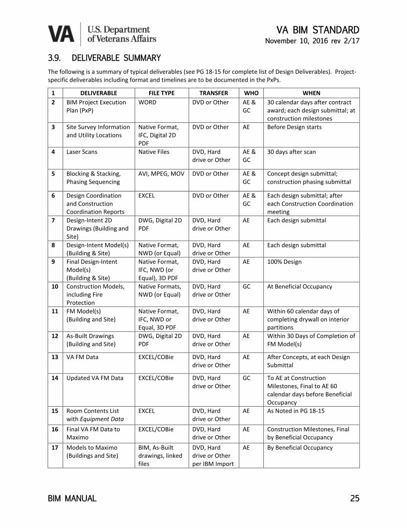
3.9. DELIVERABLE SUMMARY The following is a summary of typical deliverables (see PG 18-15 for complete list of Design Deliverables). Project-specific deliverables including format and timelines are to be documented in the PxPs.
1 DELIVERABLE FILE TYPE TRANSFER WHO WHEN 2 BIM Project Execution
Plan (PxP) WORD DVD or Other AE &
GC 30 calendar days after contract award; each design submittal; at construction milestones
3 Site Survey Information and Utility Locations
Native Format, IFC, Digital 2D PDF
DVD or Other AE Before Design starts
4 Laser Scans Native Files DVD, Hard drive or Other
AE & GC
30 days after scan
5 Blocking & Stacking, Phasing Sequencing
AVI, MPEG, MOV DVD or Other AE & GC
Concept design submittal; construction phasing submittal
6 Design Coordination and Construction Coordination Reports
EXCEL DVD or Other AE & GC
Each design submittal; after each Construction Coordination meeting
7 Design-Intent 2D Drawings (Building and Site)
DWG, Digital 2D PDF
DVD, Hard drive or Other
AE Each design submittal
8 Design-Intent Model(s) (Building & Site)
Native Format, NWD (or Equal)
DVD, Hard drive or Other
AE Each design submittal
9 Final Design-Intent Model(s) (Building & Site)
Native Format, IFC, NWD (or Equal), 3D PDF
DVD, Hard drive or Other
AE 100% Design
10 Construction Models, including Fire Protection
Native Formats, NWD (or Equal)
DVD, Hard drive or Other
GC At Beneficial Occupancy
11 FM Model(s) (Building and Site)
Native Format, IFC, NWD or Equal, 3D PDF
DVD, Hard drive or Other
AE Within 60 calendar days of completing drywall on interior partitions
12 As-Built Drawings (Building and Site)
DWG, Digital 2D PDF
DVD, Hard drive or Other
AE Within 30 Days of Completion of FM Model(s)
13 VA FM Data EXCEL/COBie DVD, Hard drive or Other
AE After Concepts, at each Design Submittal
14 Updated VA FM Data EXCEL/COBie DVD, Hard drive or Other
GC To AE at Construction Milestones, Final to AE 60 calendar days before Beneficial Occupancy
15 Room Contents List with Equipment Data
EXCEL DVD, Hard drive or Other
AE As Noted in PG 18-15
16 Final VA FM Data to Maximo
EXCEL/COBie DVD, Hard drive or Other
AE Construction Milestones, Final by Beneficial Occupancy
17 Models to Maximo (Buildings and Site)
BIM, As-Built drawings, linked files
DVD, Hard drive or Other per IBM Import
AE By Beneficial Occupancy

VA BIM STANDARD November 10, 2016 rev 2/17
BIM MANUAL 26
4. USING BIM ON A PROJECT BIM must be used for the following purposes. Some are required for either the AE Team (AE) or the General Contractor (GC) while others may be required of both. Each required purpose is denoted with the following:
AE Requirement
GC Requirement
BIM Uses Summary Table
Section BIM Use AE GC
4.1. EXISTING CONDITIONS • •
4.2. SITE MODELING • •
4.3. DATA • •
4.4. EQUIPMENT MANAGEMENT • •
4.5. VERIFICATION, ANALYSIS, & DECISION SUPPORT • •
4.6. QUANTITY TAKE OFFS • •
4.7. SUSTAINABILITY & ENERGY •
4.8. CONSTRUCTABILITY REVIEWS AND SYSTEMS COORDINATION • •
4.9. COMMISSIONING & HANDOVER • •
5.0. USE OF NEW TECHNOLOGY/TECHNIQUES • •
4.1. EXISTING CONDITIONS Existing conditions are to be modeled within the discipline models. Laser or photogrammetry scanning is required to verify existing interior conditions if the accuracy of existing documentation is suspect. The AE and the GC are individually responsible for implementing any process or technology required to adequately field-verify existing conditions needed in the performance of their contractual obligations.
• Existing Site and Utilities Modeling
• Existing Building Conditions, Building Systems Locations
• Areas of Historical Significance
4.2. SITE MODELING Existing surface conditions, underground and above utilities must be modeled in civil information modeling software.
• Model all existing surface site conditions, underground utilities, proposed project site and utility design and site as-built construction.
• FM Model(s) for the site are limited to new underground utility work or required changes to existing utilities within the construction site limits and includes on-site to off-site utility tie-ins where they occur.
• Physical Security and Survivability features must be modeled.
AE
AE
AE
AE
AE
AE
GC
AE

VA BIM STANDARD November 10, 2016 rev 2/17
BIM MANUAL 27
4.3. DATA Create, update, and maintain all model objects and required data as required. Models and/or associated databases must contain the necessary data to produce project documentation for construction and to enable VA’s facility lifecycle management objectives.
4.4. EQUIPMENT MANAGEMENT BIM must be used to facilitate PRC coordination during design, activations, and construction. This includes all activities for equipment utility hook-ups, the First and Second Test-fit activities, the creation of the Room Contents List, and selection of the Final equipment, etc. The use of VA Spatial & Equipment Data will provide the GUIDS30 and standards to allow reuse of the data.
4.5. VERIFICATION, ANALYSIS, & DECISION SUPPORT
4.5.1. Concept Options (Blocking and Stacking Departments) BIM must be used when showing departmental blocking and stacking options when providing conceptual planning option comparisons. When swing space or phasing is also being considered, the use of BIM animations tied to scheduling software (4D) must be provided.
4.5.2. Space Size Verification • Tabular Space Comparisons
The SEPS PFD report for the required Net Square Footage (NSF) of each room and the Departmental Gross Square Footages (DGSF) will be compared against the Proposed Design. The space tabular comparison required by PG 18-15 must be an extract from the BIM and reflect the current proposed design at the time of submittal. All SEPS room codes, room names, and actual square footages must be shown in each room or department floorplans.
• Defining Departments Departments must be measured in BIM according to VA Space Measurement Standards. Each Department must be color coded to help in reading the Model and 2D Drawings.
4.5.3. Room Data Sheets Room Data Sheets for each representational room type must be created from BIM to validate that the room and equipment test-fit is adequate. Each room type must include a floorplan, elevations, reflected ceiling plan, a room 3D PDF (instead of an axonometric view) and all the equipment in the room with the required properties, as noted in VA Spatial and Equipment Data Spreadsheet and the PG 18-15 AE Submission Requirements. (See Appendix A - Room Data Sheet Example)
30 GUID = Globally Unique Identifier used by computers to manage data
GC AE
AE
AE
AE
AE
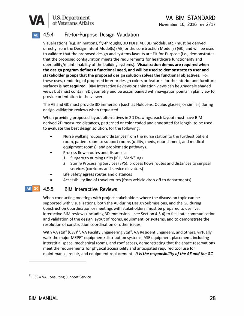
VA BIM STANDARD November 10, 2016 rev 2/17
BIM MANUAL 28
4.5.4. Fit-for-Purpose Design Validation Visualizations (e.g. animations, fly-throughs, 3D PDFs, 4D, 3D models, etc.) must be derived directly from the Design-Intent Model(s) (AE) or the construction Model(s) (GC) and will be used to validate that the proposed design and systems layouts are Fit-for-Purpose (i.e., demonstrates that the proposed configuration meets the requirements for healthcare functionality and operability/maintainability of the building systems). Visualization demos are required when the design program defines a functional need, and will be used to demonstrate to user and stakeholder groups that the proposed design solution solves the functional objectives. For these uses, rendering of proposed interior design colors or features for the interior and furniture surfaces is not required. BIM Interactive Reviews or animation views can be grayscale shaded views but must contain 3D geometry and be accompanied with navigation points in plan view to provide orientation to the viewer.
The AE and GC must provide 3D immersion (such as HoloLens, Oculus glasses, or similar) during design validation reviews when requested.
When providing proposed layout alternatives in 2D Drawings, each layout must have BIM derived 2D measured distances, patterned or color coded and annotated for length, to be used to evaluate the best design solution, for the following:
• Nurse walking routes and distances from the nurse station to the furthest patient room, patient room to support rooms (utility, meds, nourishment, and medical equipment rooms), and problematic pathways.
• Process flows routes and distances: 1. Surgery to nursing units (ICU, Med/Surg) 2. Sterile Processing Services (SPS), process flows routes and distances to surgical
services (corridors and service elevators) • Life Safety egress routes and distances • Accessibility line of travel routes (from vehicle drop-off to departments)
4.5.5. BIM Interactive Reviews When conducting meetings with project stakeholders where the discussion topic can be supported with visualizations, both the AE during Design Submissions, and the GC during Construction Coordination or meetings with stakeholders, must be prepared to use live, interactive BIM reviews (including 3D immersion – see Section 4.5.4) to facilitate communication and validation of the design layout of rooms, equipment, or systems, and to demonstrate the resolution of construction coordination or other issues.
With VA staff (CSS)31, VA Facility Engineering Staff, VA Resident Engineers, and others, virtually walk the major MEPFT equipment/distribution systems, ASE equipment placement, including interstitial space, mechanical rooms, and roof access, demonstrating that the space reservations meet the requirements for physical accessibility and anticipated required tool use for maintenance, repair, and equipment replacement. It is the responsibility of the AE and the GC
31 CSS = VA Consulting Support Service
AE
AE GC

VA BIM STANDARD November 10, 2016 rev 2/17
BIM MANUAL 29
to obtain written confirmation by VA engineering (CSS) and maintenance personnel (Medical Center Chief Engineer) that the physical accessibility shown in the final coordination review is adequate. The GC must install to the Construction Coordination model locations approved by VA.
4.5.6. Visually Monitored Spaces In visually monitored spaces (hallways, waiting areas, security, etc.) create camera views simulating visual control (full range of sight) for facility personnel (e.g., nurses and security guards). Cameras views must simulate line of sight from seated position at monitoring stations as well as walking or standing positions. The walking/standing horizontal line-of-sight for cameras will be 5’-6” above finish floor. The seated horizontal line-of-sight for cameras will be 3’-10” above finish floor with the camera’s vertical axis 0’-9” from counter/desk edge if present. Simulate BIM viewpoints from personnel’s horizontal line-of-sight and fully pan left and right to show the extents of visually monitored spaces. Provide BIM interactive reviews for the following areas:
• Complex diagnostic rooms (i.e., Operating rooms, Cardiac Cath, Hybrids) • Main entrances • Additional key areas as identified by the project team • Patient Observation
o Nurse’s view from nurse’s station down patient corridor: Simulate nurse’s line-of-sight from a seated position observing corridors to be visually monitored.
o Mental Health or other units monitored by cameras, show camera point-of-view
o Nurse’s view from hallway to patient in room: Simulate nurse typical pathway along hall. Show nurse’s line-of-sight along pathway to patient in bed. Graphically shade areas on the 2D plans where there is no nurse line-of-sight.
4.5.7. Fire Partitions, Emergency Exiting, Accessibility Demonstrate that the proposed design meets VA and code criteria by graphically showing through BIM walk-throughs the fire partitions, emergency exiting, and accessibility pathways.
4.5.8. Communicating Design Aesthetic Visualizations must be progressively rendered for each Design Deliverable review. The visualizations (pictures/graphics/still images and fly-throughs/animations) derived from and consistent with the current BIM must be provided to communicate the design to project stakeholders. Fly/walk/ride-throughs are defined as animated views that progress around or through the model along a predetermined path to demonstrate the design and constructability of the project. Acceptable formats are AVI, MPEG, and MOV.
• Fly-throughs can have variable heights as defined by the AE or as requested by VA. These animated views can be around exterior or interstitial spaces
• Walk-throughs are to be set at 5’-6” above finish floor unless otherwise requested by VA.
• Ride–throughs are to be set a 3’-10” above finish floor to demonstrate the view from a wheelchair
AE
AE
AE
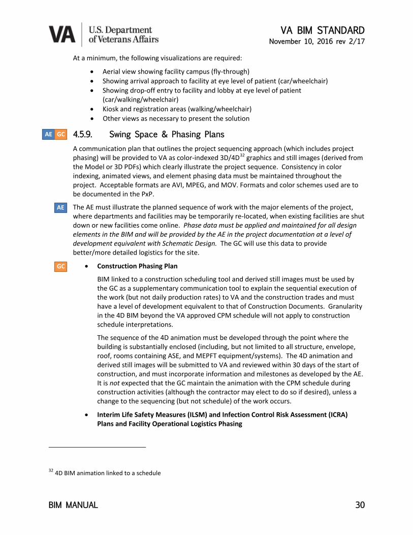
VA BIM STANDARD November 10, 2016 rev 2/17
BIM MANUAL 30
At a minimum, the following visualizations are required:
• Aerial view showing facility campus (fly-through) • Showing arrival approach to facility at eye level of patient (car/wheelchair) • Showing drop-off entry to facility and lobby at eye level of patient
(car/walking/wheelchair) • Kiosk and registration areas (walking/wheelchair) • Other views as necessary to present the solution
4.5.9. Swing Space & Phasing Plans A communication plan that outlines the project sequencing approach (which includes project phasing) will be provided to VA as color-indexed 3D/4D32 graphics and still images (derived from the Model or 3D PDFs) which clearly illustrate the project sequence. Consistency in color indexing, animated views, and element phasing data must be maintained throughout the project. Acceptable formats are AVI, MPEG, and MOV. Formats and color schemes used are to be documented in the PxP.
The AE must illustrate the planned sequence of work with the major elements of the project, where departments and facilities may be temporarily re-located, when existing facilities are shut down or new facilities come online. Phase data must be applied and maintained for all design elements in the BIM and will be provided by the AE in the project documentation at a level of development equivalent with Schematic Design. The GC will use this data to provide better/more detailed logistics for the site.
• Construction Phasing Plan
BIM linked to a construction scheduling tool and derived still images must be used by the GC as a supplementary communication tool to explain the sequential execution of the work (but not daily production rates) to VA and the construction trades and must have a level of development equivalent to that of Construction Documents. Granularity in the 4D BIM beyond the VA approved CPM schedule will not apply to construction schedule interpretations.
The sequence of the 4D animation must be developed through the point where the building is substantially enclosed (including, but not limited to all structure, envelope, roof, rooms containing ASE, and MEPFT equipment/systems). The 4D animation and derived still images will be submitted to VA and reviewed within 30 days of the start of construction, and must incorporate information and milestones as developed by the AE. It is not expected that the GC maintain the animation with the CPM schedule during construction activities (although the contractor may elect to do so if desired), unless a change to the sequencing (but not schedule) of the work occurs.
• Interim Life Safety Measures (ILSM) and Infection Control Risk Assessment (ICRA) Plans and Facility Operational Logistics Phasing
32 4D BIM animation linked to a schedule
AE GC
AE
GC

VA BIM STANDARD November 10, 2016 rev 2/17
BIM MANUAL 31
For existing medical care locations, provide BIM 3D/4D and/or still images for site Logistics Phasing must be used to identify and coordinate vehicular and pedestrian traffic rerouting, street closures, utility rerouting or shutdowns, pedestrian route protection, security protection, and protection of continuing facility operations (e.g., infection control measures, deliveries, etc.) during construction and to communicate the proposed approach for approval from VA, and to inform the community, public utilities, and other interested parties. Prior to construction start, VA will review the GC’s site logistics plans(s) to ensure that any impacts construction activities have outside the site boundaries or to facility operations that will continue during construction are mitigated.
4.6. QUANTITY TAKE OFF Material quantities extracted from the Design-Intent Model should be used with caution because the Design-Intent Model is not created for this purpose. Contractor is obligated to determine, and assumes all risk for, the suitability of the Design-Intent BIM for material quantity takeoffs.
4.7. SUSTAINABILITY & ENERGY
4.7.1. Daylight, and Sun Studies In order to appropriately inform the design solution during the design process, an accurately geo-located Model (as described in Section 2.9) must be used as the basis when performing these studies. Also refer to VA Sustainable Design Manual.
4.7.2. Energy Analysis Studies Model information must be used as the basis for energy analysis studies/energy modeling. It is preferred, but not required, that the AE utilize energy modeling and sustainable design software that uses BIM data directly imported for analysis.
4.8. CONSTRUCTABILITY AND SYSTEMS COORDINATION
4.8.1. Coordination Management33 VA requires coordination/interference management be conducted to ensure that there is adequate space for the equipment/systems for layout and accessibility and maintenance, and that spatial interferences are resolved before construction fabrication and installation. The AE is responsible for performing Design Coordination with their consultant’s models and the GC is responsible for performing Construction Coordination with their sub-trade’s models during their respective phases of the project for the building components (especially all MEPFT systems) and site utilities. The AE is responsible for ensuring that the architectural construction details reflect the modeled space reservations needed for building distribution systems and equipment, and include pipe sloping and insulation where required.
33 The commonly used term, “Clash Detection,” is a part of Coordination Management
AE
AE GC
AE
GC AE
VA BIM STANDARD November 10, 2016 rev 2/17
BIM MANUAL 32
Space reservations for maintenance of building systems and equipment, routing reservations for medical technology systems, business systems, and fire protection systems must be included in all Design and Construction Coordination activities with other building systems to assure that there is adequate layout and maintenance space for all systems. The GC must ensure that no other trades encroach on these reserved spaces.
Each unique systems model (e.g. structural, interior, mechanical, etc.) will be combined using interference detection software that performs automated conflict (clash-detection) identification. Particular care must be given to the structural, architectural, MEPFT, space reservations, existing (if locations are known) and new underground site utility systems during coordination meetings. All slope, insulation, clearance, and access requirements specified in the contract documents must be included for interference detection purposes; model elements must not be excluded based solely on the size of the element.
BIM files submitted for Coordination must have all extraneous 2D and 3D references and elements stripped from the models. During their respective coordination processes, the AE and GC must ensure:
• The location of building equipment and distribution systems, ASE Equipment, and Medical technology items do not interfere with the locations of other systems and parts of the building (e.g., walls, structure, etc.) and that there is adequate space around the equipment/systems so they are functional, repairable, replaceable, maintainable, and constructible.
• Design and Construction Coordination of underground site utilities, both existing and new. Actual routing locations of existing underground site utilities may be unverified or unknown. Where this is the case they must be modeled and identified as “Location unverified: for information only.” New routing must be located in the FM Model(s) as per the as-built locations provided by the GC.
• Formal Design and Construction Coordination meetings must be regularly held (generally weekly) to fully coordinate the work.
• Prior to each scheduled Coordination meeting, an updated interference report will be issued to the respective Team members by the Team Model Manager to help facilitate and manage issue resolution.
• The AE at each Design Deliverable, and the GC after each Coordination meeting during construction until Coordination is complete, will provide VA with a Design or Construction Management Progress Report in Excel of the outstanding critical coordination issues for VA Quality Assurance review. Items that will not be tracked will be identified in the respective PxPs.
• The GC is responsible to ensure that equipment and systems are installed according to the Construction Coordinated model locations, which have been signed off by VA Facility Management personnel, and are refined from the AE Design Coordinated model

VA BIM STANDARD November 10, 2016 rev 2/17
BIM MANUAL 33
locations. Any deviations that impinge on space reservations as noted in VA BIM Standards must be approved by VA in writing.
• VA’s Standard of Care for BIM Objects used in Design Coordination is a minimum of LOD 30034 and for Construction Coordination is a minimum of LOD 350.
• The Design and Construction Coordination are required to use IFC coordination views and exchange environments.
• The GC must provide access on demand to VA Senior/Resident Engineer to the models and to observe the Construction Coordination effort.
4.8.2. Integrated Work Teams The AE must integrate their cost estimator with their project team to the fullest extent possible so that decision making and real time design cost estimating can be done concurrently. All AE consultants or GC subcontractors must participate in the BIM model-view coordination process when their work is being addressed. These coordination strategies must be documented in the respective PxPs.
4.9. COMMISSIONING AND HANDOVER Commissioning is not only important to achieve operational efficiencies and to assure that the facility, and its systems and assemblies are ready to accept patients. Commissioning also provides a rich trove of asset data that is important for populating the CMMS (Maximo) that runs the building. The GC and/or VA Commissioning Agent must supply all the commissioning data in the correct format to the AE that is noted in the VA FM Data Spreadsheet.
4.10. USE OF NEW TECHNOLOGY/TECHNIQUES The design and construction efficiencies that are enabled by adopting new technologies and management techniques are rapidly changing how new facilities are designed and constructed. It is important that VA, like other healthcare owners, enjoy the advantages of speed to market and other efficiencies through business process changes enabled by BIM and Lean technologies and management practices that accrue to owners and the AE and GC alike. To this end, the AE and GC must provide their strategy and implementation plans for using the techniques noted under this section within 30 days of contract award to VA, including new technologies and management techniques not noted, and provided in their respective PxPs.
4.10.1. BIM Integrated Specifications VA encourages the use of specification software that is integrated with BIM.
4.10.2. BIM, GIS, and Laser Scanning During Construction The AE and GC must tie BIM models to GIS and laser scanning (where required) for accurate building layouts. General Contractors must integrate laser systems and other construction
34 See the Associated General Contractors of America (AGC) BIMForum document on Level of Development (LOD)
GC AE
AE GC
GC
AE

VA BIM STANDARD November 10, 2016 rev 2/17
BIM MANUAL 34
technologies and management strategies into their delivery methods. Laser scans performed by the AE or the GC must be provided to VA in their native formats.
4.10.3. Modular Building Components Off-site/modular prefabrication of repeatable systems saves time, increases productivity, reduces material waste, and improves worker safety and working conditions (and hence construction quality). Consequently, the AE must design repetitive building components (patient bathrooms, patient headwalls, corridor MEPFT overhead distribution systems, etc.) in such a fashion that they can be adapted for construction by the GC as modular assemblies whenever possible in Design-Bid-Build procurements. In Design/Build procurements these systems (at a minimum) are required to be designed and constructed for off-site/modular prefabrication.
4.10.4. Use of Electronic Data Tools for Commissioning The Commissioning Agent, whether under contract to the GC or VA, must use electronic software that allows data gathered during the commissioning effort, such as tracking workflow, work assignments, work checklist, punch lists, equipment testing data and metrics, etc., to be reused for other purposes, such as providing Facility Management data for Maximo.
4.10.5. Virtual Mockups The GC must use virtual mockups of all locations where analyzing the constructability of a system or assembly needs a very high level of detail (e.g. complex façade and roof system interfaces that are geometrically challenging, form work, glazing, tie-back, masonry, flashing, etc.) in order to increase planning, sequencing, and coordination of the installation. For complicated systems with several trade subcontractors and materials, an image-based sequence of work (step-by-step instruction formatting) must be distributed to the trades and other team members.
4.10.6. Other Proposed Strategies VA desires that the very best software, management strategies, and Lean techniques be used to achieve schedule, quality, and functional objectives for VA projects. VA encourages AEs and GCs to take advantage of innovation and best practices that are improving the design and construction industry.
GC
GC AE
GC
GC AE
VA BIM STANDARD November 10, 2016 rev 2/17
BIM MANUAL 35
5. DEFINITIONS Acquisition Codes (VV, VC, CC, R) – Codes that identify responsibility for purchasing and installing Personal and Real Property Equipment. VV = government furnished/government installed; VC = government furnished/contractor installed; CC = contractor furnished/contractor installed; and R = reused.
AE - the Architect/Engineering firm, along with all the consultants hired by the AE to produce the Design-Intent Model, contract documents, and all other documentation necessary to support bidding and construction.
Architecturally Significant Equipment (ASE) – Medical and non-medical equipment items that are customarily installed by the manufacturer or vendor that can impact the construction critical path schedule and/or requires connection to/accommodation by building infrastructure. Close coordination between VA Activations and procurement, equipment planners, construction contractor (GC), installer/vendor, and AE, is required.
BIM – Building Information Model(ing): various definitions are used within industry. BIM is the process, the Model, and the management of creating digital information for design and construction. The context defines the acronym’s meaning.
CAD – Computer Aided Design
Construction Model(s) – the GC models used for construction purposes on the project.
Design-Intent Model - a complete and coordinated expression of the AE's design. Final equipment and materials choices are based on performance specifications provided by the AE, allowing some variation, but equivalent, equipment and materials to be selected by the GC during construction. Therefore, the Design-Intent Model will be augmented with submittals, shop drawings and substitution requests provided by the GC. Moreover, the GC is responsible for the means and methods of construction, which are similarly not contained in the Design-Intent Model. The GC is, however, responsible for providing, installing, and constructing a complete and functional project, which includes requirements explicitly contained in the Design-Intent Model and requirements that, using normal industry practices, are reasonably inferable from the Design-Intent Model and necessary to achieve a complete, functional, and maintainable project. Design-Intent model also refers to individual models such as a particular discipline model or in whole such as a composite or federated model.
Drawing Deliverable Requirements (DDR) – defines 2D drawing creation derived from either CAD or BIM.
Federated Model – an assembly of various discipline or trade models into a composite 3D view.
FM Model - the Design-Intent Model updated with actual constructed locations for equipment, systems, walls, etc. which will be used for Facility Management. This is intended to be a lightweight model with enough detail to enable facilities management operations without overly detailed elements.
Furnishings, Fixtures, & Equipment (FFE) – Movable and fixed furnishings, fixtures, non-med equipment.
General Contractor (GC) - the General Contractor and all the sub-contractors under contract to the GC who are involved in the construction/fabrication of a specific facility.
Globally Unique Identifier (GUID) - Machine readable identifying codes that must be preserved through generation and regeneration of digital deliverables so that a given object (space, equipment, etc.) can be tracked properly. GUIDs are automatically assigned by the Space and Equipment Planning System

VA BIM STANDARD November 10, 2016 rev 2/17
BIM MANUAL 36
(SEPS), BIM, and other software. BIM software documentation should be consulted to determine how copied equipment object instances are handled in outputted reports and how they are handled internal to the software.
Industry Foundation Classes (IFC) - An international standard schema for data exchange.
MEPFT Equipment - Mechanical, Electrical, Plumbing, Fire protection, Technology (including medical low voltage systems, structured cabling) equipment such as generators, transformers, electrical fixtures, air handling units, boilers, chillers, VAV boxes, plumbing fixtures, and communication technology cable trays.
MEPFT Systems - the distribution systems for piping, conduits, or ducting (including but not limited to Mechanical, Electrical, Plumbing, Fire Protection, and Technology (including medical low voltage systems, structured cabling, communications).
Model – refers to an individual model containing various components, a combination of models, AND/OR the process of modeling in general. The most appropriate meaning within the context of use would apply.
Project Data Security Plan – the documented protocol that defines how the data will be protected from loss or unauthorized access during creation, exchange, and retention.
Program for Design (PFD) - the baseline SEPS design program as provided by VA that identifies the rooms, net square footage, and other requirements for the project.
Project Room Contents (PRC) - A SEPS export file providing preliminary room contents for each room.
PxP – BIM Execution Plan, a BIM project management plan internal to the working teams, which outlines the management roles, division of work between prime/consultants or general contractor/sub-contractors for modeling responsibilities, standards, software versions, etc. used for model creation on a project.
SEPS - the Space and Equipment Planning System (SEPS) is a medical planning software shared by VA and DoD which provides the space Program for Design (PFD) and preliminary Project Room Contents (PRC) for a new project.

VA BIM STANDARD November 10, 2016 rev 2/17
BIM MANUAL 37
6. ACKNOWLEDGEMENTS This document was prepared by the National Institute of Building Sciences for: U.S. Department of Veterans Affairs
Office of Construction & Facility Management – Stella Fiotes, AIA, Executive Director Office of Facilities Planning – Lloyd Siegel, FAIA, Associate Executive Director Facilities Standards Service – Donald Myers, Director VA BIM Program Manager – Renée Tietjen, AIA, VA BIM Standard Project Manager
National Institute of Building Sciences Nanne Davis Eliot – NIBS Project Manager; Roger Grant, Earle Kennett Johnny Fortune – BIM Director, Bullock Tice Associates, Editor, Layout, Superhero
VA BIM Standard would not have been possible without the generosity of many people and organizations that have contributed their expertise and help, including permission to liberally adapt their excellent work for VA’s use. Their willingness to share is deeply appreciated and is a shining example of the American commitment to support our veterans.
This list of contributors represents our major contributors. There are many others who, by their example or through public forum discussions, have also influenced these standards and are too numerous to name individually. That fact doesn’t reduce our gratitude.
Many thanks to everyone!
Renée Tietjen, AIA RLA LEED-AP VA BIM Program Manager
ORGANIZATION - OWNER/CONSULTING FIRM – CONSULTANT • JKN Solutions – Malcolm Junkin • VA Palo Alto Healthcare System - Stephen G.
McGrath, VA Supervisory Engineer • HDR – Dennis Patnode • EcoDomus – Igor Starkov • Onuma, Inc. – Kimon Onuma • USACE - Steve Hutsell, Van Woods, and
USACE/Industry BIM and CIM Consortia (UIBCC) • AECOM – Matt Anderle • Hanson Bridgett, LLP - Howard Ashcraft • Kristine Fallon Associates, Inc. - Kristine Fallon,
FAIA; Danielle Gran • CFM Central Region – Daniel J. Therrien,
Director, Facilities Planning Support • Project Eagle, VA Denver Medical Center – Todd
Bofinger, Senior Resident Engineer • Massachusetts Port Authority BIM Guidelines -
Dr. Lucianna Burdi/AEC Infosystems - Dianne Davis
• Los Angeles Community College LACCD Building Information Modeling Standards - Magdalen Hron/AECOM - Jim Youngblood
• gafcon – John Turner
• GSA BIM Guide 07 Version 1.0 • Yeats Construction Company – Benjamin Crosby • Ohio State University - Joe Porostosky • Mayo Clinic – Andy Jizba • Denver International Airport - Brendan Dillion • Walsh Construction – Steve Cook • VAH Activations – Patrick Hull • DPR – Daniel Gonzales • Perkins+Will – Matt Peterman • HOK – James Vandezande • John Poe Architects – Nathan Schwab • Cumming – Abe Schainker • Skanska – Jennifer Macks • Polt Design Group – Jim Knapp • WB Engineering – Greg Brenner • Balfour Beatty Construction – Jason Reece • HDR – Ron Croke • AEC Infosystems – Dianne Davis • MBP – Ralph Kreider • Jim Bedrick • Bob Mauck Cover Photographs of the new VA Louisville Medical Center by URS/SmithGroup Joint Venture