V088 E1 03+CX Designer+UsersManual
111
CX-Designer Ver. 2.1 NS-CXDC1-V2 Cat. No. V088-E1-03 NS-Series USER’S MANUAL
description
omron user manual plc
Transcript of V088 E1 03+CX Designer+UsersManual
Cat. No. V088-E1-03
CX-DesignerVer. 2.1NS-CXDC1-V2
NS-Series
USER’S MANUAL
CX-DesignerVer. 2.1NS-CXDC1-V2User’s ManualRevised July 2007

iv
Notice:OMRON products are manufactured for use according to proper procedures by a qualified operatorand only for the purposes described in this manual.
The following conventions are used to indicate and classify precautions in this manual. Always heedthe information provided with them. Failure to heed precautions can result in injury to people or dam-age to property.
!DANGER Indicates an imminently hazardous situation which, if not avoided, will result in death orserious injury. Additionally, there may be severe property damage.
!WARNING Indicates a potentially hazardous situation which, if not avoided, could result in death orserious injury. Additionally, there may be severe property damage.
!Caution Indicates a potentially hazardous situation which, if not avoided, may result in minor ormoderate injury, or property damage.
OMRON Product ReferencesAll OMRON products are capitalized in this manual. The word “Unit” is also capitalized when it refers toan OMRON product, regardless of whether or not it appears in the proper name of the product.
The abbreviation “Ch,” which appears in some displays and on some OMRON products, often means“word” and is abbreviated “Wd” in documentation in this sense.
The abbreviation “PLC” means Programmable Controller. “PC” is used, however, in some Program-ming Device displays to mean Programmable Controller.
Visual AidsThe following headings appear in the left column of the manual to help you locate different types ofinformation.
Note Indicates information of particular interest for efficient and convenient opera-tion of the product.
1,2,3... 1. Indicates lists of one sort or another, such as procedures, checklists, etc.
TerminologyNS-series PT A Programmable Terminal in the NS Series manufactured by OMRON.
PLC A Programmable Logic Controller manufactured by OMRON.
Host A PLC, factory computer, personal computer or other controller controlling an NS-series PT.
NS-Designer The NS-NSDC1-V@ NS-Designer produced by OMRON. The NS-Designer is anapplications software package that enables creating screen data for NS-series PTs.
CX-One The CXONE-AL@@C-E CX-One FA Integrated Tool Package produced by OMRON.This applications software package provides all of the software packages for OMRONPLCs and components.
CX-Designer The NS-CXDC1-V2 CX-Designer produced by OMRON.
NS-Runtime The NS-Runtime software runs on Windows XP and provides the same functionalityas an NS-series PT.
v

OMRON, 2005All rights reserved. No part of this publication may be reproduced, stored in a retrieval system, or transmitted, in any form, orby any means, mechanical, electronic, photocopying, recording, or otherwise, without the prior written permission ofOMRON.
No patent liability is assumed with respect to the use of the information contained herein. Moreover, because OMRON is con-stantly striving to improve its high-quality products, the information contained in this manual is subject to change withoutnotice. Every precaution has been taken in the preparation of this manual. Nevertheless, OMRON assumes no responsibilityfor errors or omissions. Neither is any liability assumed for damages resulting from the use of the information contained inthis publication.
vi
TABLE OF CONTENTS
SECTION 1Overview . . . . . . . . . . . . . . . . . . . . . . . . . . . . . . . . . . . . . . . . . 1
1-1 Features of the CX-Designer . . . . . . . . . . . . . . . . . . . . . . . . . . . . . . . . . . . . . . . . . . . . . . . . . 2
1-2 Basic Operation Procedures. . . . . . . . . . . . . . . . . . . . . . . . . . . . . . . . . . . . . . . . . . . . . . . . . . 5
SECTION 2Setting Up the CX-Designer. . . . . . . . . . . . . . . . . . . . . . . . . . 11
2-1 Preparations for Installation. . . . . . . . . . . . . . . . . . . . . . . . . . . . . . . . . . . . . . . . . . . . . . . . . . 12
2-2 Installing the CX-Designer . . . . . . . . . . . . . . . . . . . . . . . . . . . . . . . . . . . . . . . . . . . . . . . . . . 13
2-3 Uninstalling . . . . . . . . . . . . . . . . . . . . . . . . . . . . . . . . . . . . . . . . . . . . . . . . . . . . . . . . . . . . . . 18
2-4 Installing USB Drivers for NS-Series PTs. . . . . . . . . . . . . . . . . . . . . . . . . . . . . . . . . . . . . . . 18
SECTION 3Basic Operations of the CX-Designer . . . . . . . . . . . . . . . . . . 25
3-1 Starting and Exiting CX-Designer. . . . . . . . . . . . . . . . . . . . . . . . . . . . . . . . . . . . . . . . . . . . . 26
3-2 Menu Commands. . . . . . . . . . . . . . . . . . . . . . . . . . . . . . . . . . . . . . . . . . . . . . . . . . . . . . . . . . 27
3-3 User Interface. . . . . . . . . . . . . . . . . . . . . . . . . . . . . . . . . . . . . . . . . . . . . . . . . . . . . . . . . . . . . 34
SECTION 4Useful Functions . . . . . . . . . . . . . . . . . . . . . . . . . . . . . . . . . . . 45
4-1 Creating Screens Using Symbols. . . . . . . . . . . . . . . . . . . . . . . . . . . . . . . . . . . . . . . . . . . . . . 46
4-2 Using Screens from Other Projects . . . . . . . . . . . . . . . . . . . . . . . . . . . . . . . . . . . . . . . . . . . . 50
4-3 Classifying Screens by Application. . . . . . . . . . . . . . . . . . . . . . . . . . . . . . . . . . . . . . . . . . . . 52
4-4 Checking and Changing Functional Object Properties without Opening Property Setting Dialog Boxes . . . . . . . . . . . . . . . . . . . . . . . . . . . . . . . . . . . . . . . . . . . . . . . . . . . . . . . . . . . . . 54
4-5 Listing and Editing Functional Object Properties . . . . . . . . . . . . . . . . . . . . . . . . . . . . . . . . . 55
4-6 Editing Overlapping Objects . . . . . . . . . . . . . . . . . . . . . . . . . . . . . . . . . . . . . . . . . . . . . . . . . 57
4-7 Creating Multi-language Labels . . . . . . . . . . . . . . . . . . . . . . . . . . . . . . . . . . . . . . . . . . . . . . 58
4-8 Checking Address Usage Status . . . . . . . . . . . . . . . . . . . . . . . . . . . . . . . . . . . . . . . . . . . . . . 59
4-9 Searching for Embedded Macros. . . . . . . . . . . . . . . . . . . . . . . . . . . . . . . . . . . . . . . . . . . . . . 60
4-10 Transferring Only Edited Data to PT. . . . . . . . . . . . . . . . . . . . . . . . . . . . . . . . . . . . . . . . . . . 61
4-11 Creating Documents . . . . . . . . . . . . . . . . . . . . . . . . . . . . . . . . . . . . . . . . . . . . . . . . . . . . . . . 62
4-12 How to Use Help . . . . . . . . . . . . . . . . . . . . . . . . . . . . . . . . . . . . . . . . . . . . . . . . . . . . . . . . . . 63
4-13 Integrated Simulation for the Entire System . . . . . . . . . . . . . . . . . . . . . . . . . . . . . . . . . . . . . 64
4-14 Setting Security for Data Transfers with the PT . . . . . . . . . . . . . . . . . . . . . . . . . . . . . . . . . . 67
4-15 Setting Symbol Names and I/O Comments for Use as Labels . . . . . . . . . . . . . . . . . . . . . . . 68
4-16 Executing Multiple Functions with a Single Operation . . . . . . . . . . . . . . . . . . . . . . . . . . . . 70
4-17 Replacing a Lamp with a Button . . . . . . . . . . . . . . . . . . . . . . . . . . . . . . . . . . . . . . . . . . . . . . 72
4-18 Creating Polygonal Lamps . . . . . . . . . . . . . . . . . . . . . . . . . . . . . . . . . . . . . . . . . . . . . . . . . . 73
4-19 Registering Contents . . . . . . . . . . . . . . . . . . . . . . . . . . . . . . . . . . . . . . . . . . . . . . . . . . . . . . . 75
4-20 Using Machine Navigator . . . . . . . . . . . . . . . . . . . . . . . . . . . . . . . . . . . . . . . . . . . . . . . . . . . 77
vii

TABLE OF CONTENTS
AppendicesA Comparison of Functions with NS-Designer . . . . . . . . . . . . . . . . . . . . . . . . . . . . . . . . . . . . 83
B Shortcut Keys . . . . . . . . . . . . . . . . . . . . . . . . . . . . . . . . . . . . . . . . . . . . . . . . . . . . . . . . . . . . 87
C Exchanging Data between NS-series Products . . . . . . . . . . . . . . . . . . . . . . . . . . . . . . . . . . . 89
Revision History . . . . . . . . . . . . . . . . . . . . . . . . . . . . . . . . . . . 91
viii
About this Manual:The CX-Designer is a software package that enables creating screens for OMRON Programmable Ter-minals. Please be sure you understand the functions and performance of the CX-Designer to ensurecorrect application of the Programmable Terminals.
Please read this manual and related manuals carefully and be sure you understand the informationprovided before attempting to use the CX-Designer.
Section 1 provides an overview of the CX-Designer and its features and explains basic operatingmethods.
Section 2 describes how to install and uninstall the CX-Designer.
Section 3 describes the CX-Designer menus and basic procedures.
Section 4 describes convenient functions of the CX-Designer.
The Appendices provide a comparison between the CX-Designer and NS-Designer, tables of short-cut keys, and data transfer procedures between different versions of NS-series PT.
ix
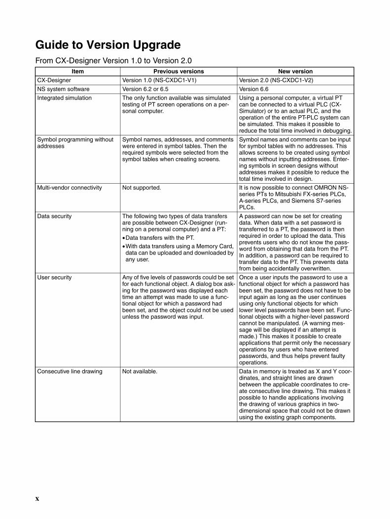
Guide to Version UpgradeFrom CX-Designer Version 1.0 to Version 2.0
Item Previous versions New version
CX-Designer Version 1.0 (NS-CXDC1-V1) Version 2.0 (NS-CXDC1-V2)
NS system software Version 6.2 or 6.5 Version 6.6
Integrated simulation The only function available was simulated testing of PT screen operations on a per-sonal computer.
Using a personal computer, a virtual PT can be connected to a virtual PLC (CX-Simulator) or to an actual PLC, and the operation of the entire PT-PLC system can be simulated. This makes it possible to reduce the total time involved in debugging.
Symbol programming without addresses
Symbol names, addresses, and comments were entered in symbol tables. Then the required symbols were selected from the symbol tables when creating screens.
Symbol names and comments can be input for symbol tables with no addresses. This allows screens to be created using symbol names without inputting addresses. Enter-ing symbols in screen designs without addresses makes it possible to reduce the total time involved in design.
Multi-vendor connectivity Not supported. It is now possible to connect OMRON NS-series PTs to Mitsubishi FX-series PLCs, A-series PLCs, and Siemens S7-series PLCs.
Data security The following two types of data transfers are possible between CX-Designer (run-ning on a personal computer) and a PT:
•Data transfers with the PT.•With data transfers using a Memory Card,
data can be uploaded and downloaded by any user.
A password can now be set for creating data. When data with a set password is transferred to a PT, the password is then required in order to upload the data. This prevents users who do not know the pass-word from obtaining that data from the PT. In addition, a password can be required to transfer data to the PT. This prevents data from being accidentally overwritten.
User security Any of five levels of passwords could be set for each functional object. A dialog box ask-ing for the password was displayed each time an attempt was made to use a func-tional object for which a password had been set, and the object could not be used unless the password was input.
Once a user inputs the password to use a functional object for which a password has been set, the password does not have to be input again as long as the user continues using only functional objects for which lower level passwords have been set. Func-tional objects with a higher-level password cannot be manipulated. (A warning mes-sage will be displayed if an attempt is made.) This makes it possible to create applications that permit only the necessary operations by users who have entered passwords, and thus helps prevent faulty operations.
Consecutive line drawing Not available. Data in memory is treated as X and Y coor-dinates, and straight lines are drawn between the applicable coordinates to cre-ate consecutive line drawing. This makes it possible to handle applications involving the drawing of various graphics in two-dimensional space that could not be drawn using the existing graph components.
x
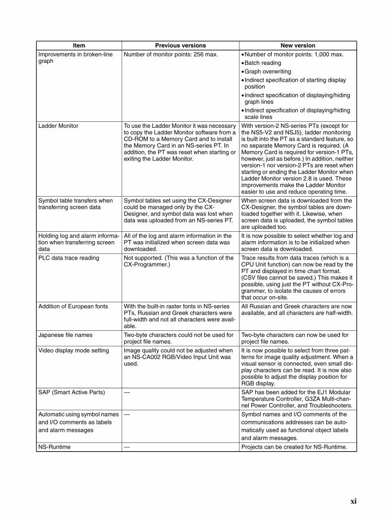
Improvements in broken-line graph
Number of monitor points: 256 max. •Number of monitor points: 1,000 max.•Batch reading
•Graph overwriting• Indirect specification of starting display
position
• Indirect specification of displaying/hiding graph lines
• Indirect specification of displaying/hiding scale lines
Ladder Monitor To use the Ladder Monitor it was necessary to copy the Ladder Monitor software from a CD-ROM to a Memory Card and to install the Memory Card in an NS-series PT. In addition, the PT was reset when starting or exiting the Ladder Monitor.
With version-2 NS-series PTs (except for the NS5-V2 and NSJ5), ladder monitoring is built into the PT as a standard feature, so no separate Memory Card is required. (A Memory Card is required for version-1 PTs, however, just as before.) In addition, neither version-1 nor version-2 PTs are reset when starting or ending the Ladder Monitor when Ladder Monitor version 2.8 is used. These improvements make the Ladder Monitor easier to use and reduce operating time.
Symbol table transfers when transferring screen data
Symbol tables set using the CX-Designer could be managed only by the CX-Designer, and symbol data was lost when data was uploaded from an NS-series PT.
When screen data is downloaded from the CX-Designer, the symbol tables are down-loaded together with it. Likewise, when screen data is uploaded, the symbol tables are uploaded too.
Holding log and alarm informa-tion when transferring screen data
All of the log and alarm information in the PT was initialized when screen data was downloaded.
It is now possible to select whether log and alarm information is to be initialized when screen data is downloaded.
PLC data trace reading Not supported. (This was a function of the CX-Programmer.)
Trace results from data traces (which is a CPU Unit function) can now be read by the PT and displayed in time chart format. (CSV files cannot be saved.) This makes it possible, using just the PT without CX-Pro-grammer, to isolate the causes of errors that occur on-site.
Addition of European fonts With the built-in raster fonts in NS-series PTs, Russian and Greek characters were full-width and not all characters were avail-able.
All Russian and Greek characters are now available, and all characters are half-width.
Japanese file names Two-byte characters could not be used for project file names.
Two-byte characters can now be used for project file names.
Video display mode setting Image quality could not be adjusted when an NS-CA002 RGB/Video Input Unit was used.
It is now possible to select from three pat-terns for image quality adjustment. When a visual sensor is connected, even small dis-play characters can be read. It is now also possible to adjust the display position for RGB display.
SAP (Smart Active Parts) --- SAP has been added for the EJ1 Modular Temperature Controller, G3ZA Multi-chan-nel Power Controller, and Troubleshooters.
Automatic using symbol names and I/O comments as labels and alarm messages
--- Symbol names and I/O comments of the communications addresses can be auto-matically used as functional object labels and alarm messages.
NS-Runtime --- Projects can be created for NS-Runtime.
Item Previous versions New version
xi
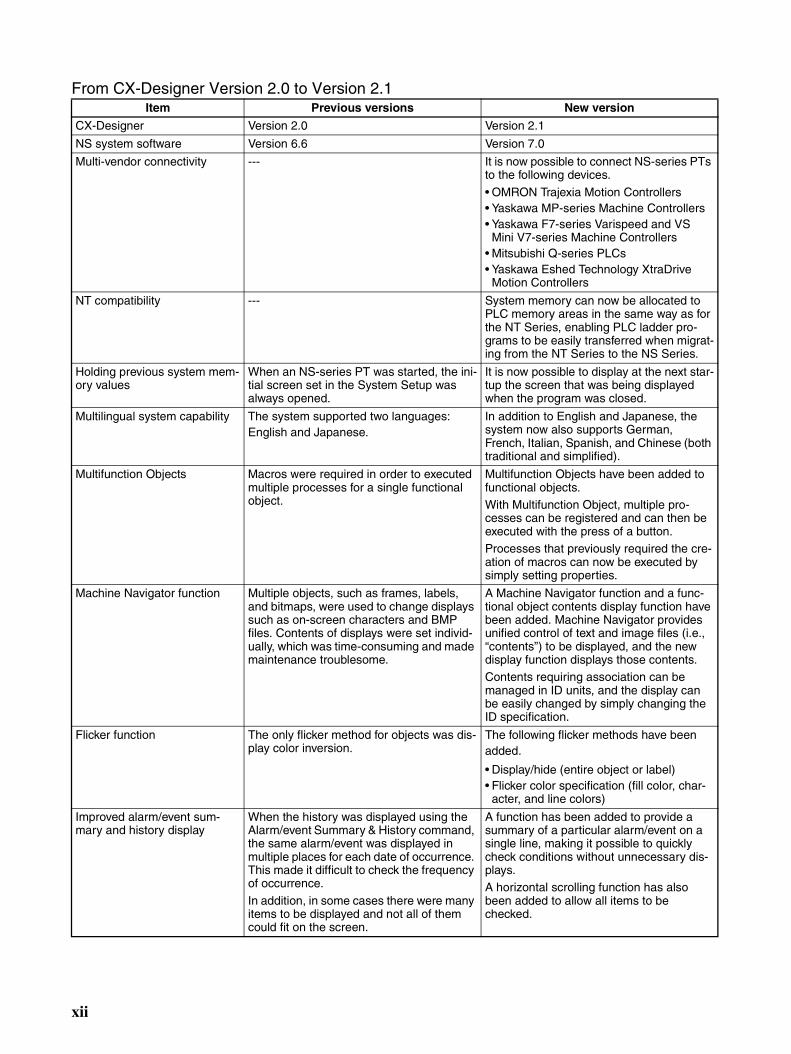
From CX-Designer Version 2.0 to Version 2.1Item Previous versions New version
CX-Designer Version 2.0 Version 2.1
NS system software Version 6.6 Version 7.0
Multi-vendor connectivity --- It is now possible to connect NS-series PTs to the following devices.
• OMRON Trajexia Motion Controllers• Yaskawa MP-series Machine Controllers• Yaskawa F7-series Varispeed and VS
Mini V7-series Machine Controllers• Mitsubishi Q-series PLCs• Yaskawa Eshed Technology XtraDrive
Motion Controllers
NT compatibility --- System memory can now be allocated to PLC memory areas in the same way as for the NT Series, enabling PLC ladder pro-grams to be easily transferred when migrat-ing from the NT Series to the NS Series.
Holding previous system mem-ory values
When an NS-series PT was started, the ini-tial screen set in the System Setup was always opened.
It is now possible to display at the next star-tup the screen that was being displayed when the program was closed.
Multilingual system capability The system supported two languages: English and Japanese.
In addition to English and Japanese, the system now also supports German, French, Italian, Spanish, and Chinese (both traditional and simplified).
Multifunction Objects Macros were required in order to executed multiple processes for a single functional object.
Multifunction Objects have been added to functional objects. With Multifunction Object, multiple pro-cesses can be registered and can then be executed with the press of a button.Processes that previously required the cre-ation of macros can now be executed by simply setting properties.
Machine Navigator function Multiple objects, such as frames, labels, and bitmaps, were used to change displays such as on-screen characters and BMP files. Contents of displays were set individ-ually, which was time-consuming and made maintenance troublesome.
A Machine Navigator function and a func-tional object contents display function have been added. Machine Navigator provides unified control of text and image files (i.e., “contents”) to be displayed, and the new display function displays those contents. Contents requiring association can be managed in ID units, and the display can be easily changed by simply changing the ID specification.
Flicker function The only flicker method for objects was dis-play color inversion.
The following flicker methods have been added.
• Display/hide (entire object or label)• Flicker color specification (fill color, char-
acter, and line colors)
Improved alarm/event sum-mary and history display
When the history was displayed using the Alarm/event Summary & History command, the same alarm/event was displayed in multiple places for each date of occurrence. This made it difficult to check the frequency of occurrence.
In addition, in some cases there were many items to be displayed and not all of them could fit on the screen.
A function has been added to provide a summary of a particular alarm/event on a single line, making it possible to quickly check conditions without unnecessary dis-plays. A horizontal scrolling function has also been added to allow all items to be checked.
xii
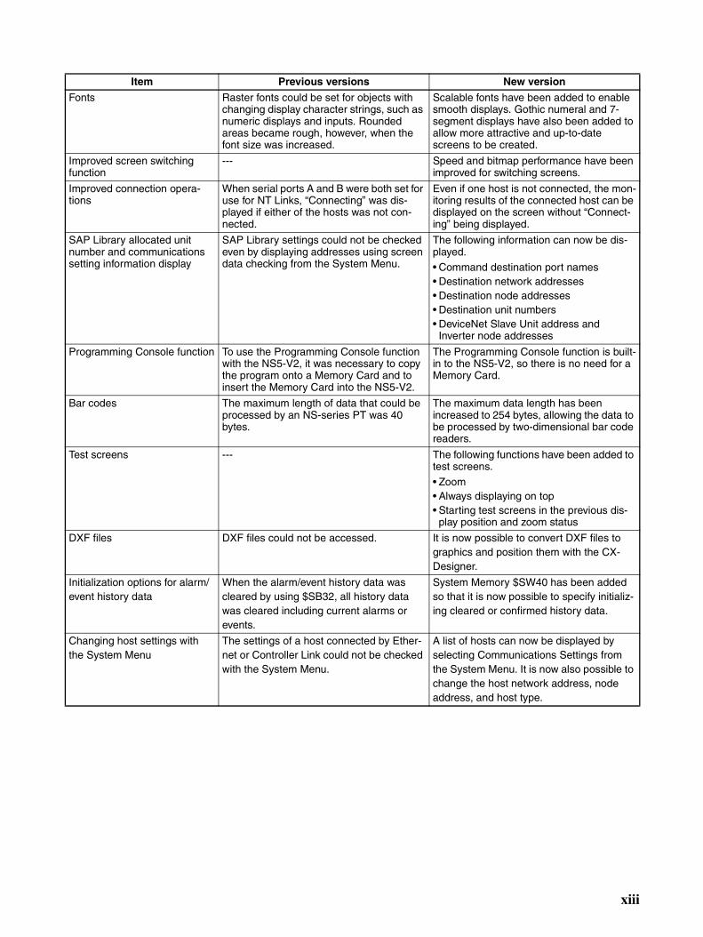
Fonts Raster fonts could be set for objects with changing display character strings, such as numeric displays and inputs. Rounded areas became rough, however, when the font size was increased.
Scalable fonts have been added to enable smooth displays. Gothic numeral and 7-segment displays have also been added to allow more attractive and up-to-date screens to be created.
Improved screen switching function
--- Speed and bitmap performance have been improved for switching screens.
Improved connection opera-tions
When serial ports A and B were both set for use for NT Links, “Connecting” was dis-played if either of the hosts was not con-nected.
Even if one host is not connected, the mon-itoring results of the connected host can be displayed on the screen without “Connect-ing” being displayed.
SAP Library allocated unit number and communications setting information display
SAP Library settings could not be checked even by displaying addresses using screen data checking from the System Menu.
The following information can now be dis-played.• Command destination port names• Destination network addresses• Destination node addresses• Destination unit numbers• DeviceNet Slave Unit address and
Inverter node addresses
Programming Console function To use the Programming Console function with the NS5-V2, it was necessary to copy the program onto a Memory Card and to insert the Memory Card into the NS5-V2.
The Programming Console function is built-in to the NS5-V2, so there is no need for a Memory Card.
Bar codes The maximum length of data that could be processed by an NS-series PT was 40 bytes.
The maximum data length has been increased to 254 bytes, allowing the data to be processed by two-dimensional bar code readers.
Test screens --- The following functions have been added to test screens.
• Zoom• Always displaying on top• Starting test screens in the previous dis-
play position and zoom status
DXF files DXF files could not be accessed. It is now possible to convert DXF files to graphics and position them with the CX-Designer.
Initialization options for alarm/event history data
When the alarm/event history data was cleared by using $SB32, all history data was cleared including current alarms or events.
System Memory $SW40 has been added so that it is now possible to specify initializ-ing cleared or confirmed history data.
Changing host settings with the System Menu
The settings of a host connected by Ether-net or Controller Link could not be checked with the System Menu.
A list of hosts can now be displayed by selecting Communications Settings from the System Menu. It is now also possible to change the host network address, node address, and host type.
Item Previous versions New version
xiii
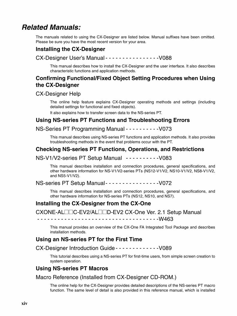
Related Manuals:The manuals related to using the CX-Designer are listed below. Manual suffixes have been omitted.Please be sure you have the most recent version for your area.
Installing the CX-Designer
CX-Designer User’s Manual - - - - - - - - - - - - - - - -V088This manual describes how to install the CX-Designer and the user interface. It also describescharacteristic functions and application methods.
Confirming Functional/Fixed Object Setting Procedures when Usingthe CX-Designer
CX-Designer HelpThe online help feature explains CX-Designer operating methods and settings (includingdetailed settings for functional and fixed objects).
It also explains how to transfer screen data to the NS-series PT.
Using NS-series PT Functions and Troubleshooting Errors
NS-Series PT Programming Manual - - - - - - - - - -V073This manual describes using NS-series PT functions and application methods. It also providestroubleshooting methods in the event that problems occur with the PT.
Checking NS-series PT Functions, Operations, and Restrictions
NS-V1/V2-series PT Setup Manual - - - - - - - - - -V083This manual describes installation and connection procedures, general specifications, andother hardware information for NS-V1/V2-series PTs (NS12-V1/V2, NS10-V1/V2, NS8-V1/V2,and NS5-V1/V2).
NS-series PT Setup Manual - - - - - - - - - - - - - - - -V072This manual describes installation and connection procedures, general specifications, andother hardware information for NS-series PTs (NS12, NS10, and NS7).
Installing the CX-Designer from the CX-One
CXONE-AL@@C-EV2/AL@@D-EV2 CX-One Ver. 2.1 Setup Manual - - - - - - - - - - - - - - - - - - - - - - - - - - - - - - - - - - - -W463
This manual provides an overview of the CX-One FA Integrated Tool Package and describesinstallation methods.
Using an NS-series PT for the First Time
CX-Designer Introduction Guide - - - - - - - - - - - - -V089This tutorial describes using a NS-series PT for first-time users, from simple screen creation tosystem operation.
Using NS-series PT Macros
Macro Reference (Installed from CX-Designer CD-ROM.)The online help for the CX-Designer provides detailed descriptions of the NS-series PT macrofunction. The same level of detail is also provided in this reference manual, which is installed
xiv
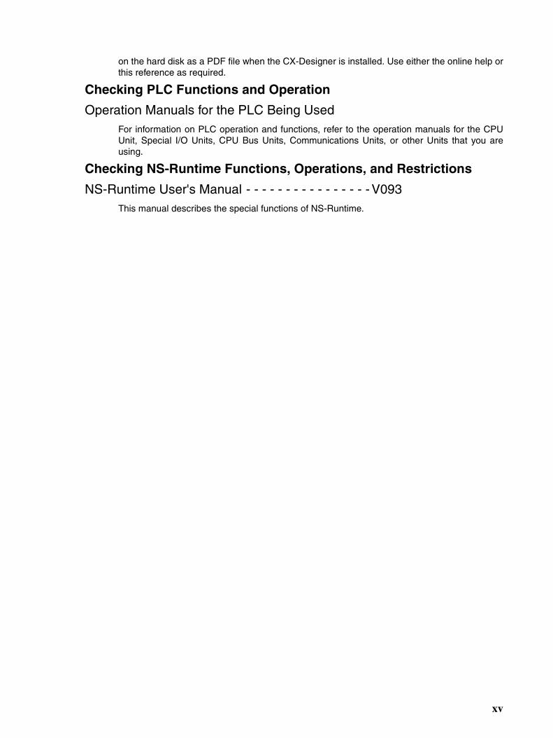
on the hard disk as a PDF file when the CX-Designer is installed. Use either the online help orthis reference as required.
Checking PLC Functions and Operation
Operation Manuals for the PLC Being UsedFor information on PLC operation and functions, refer to the operation manuals for the CPUUnit, Special I/O Units, CPU Bus Units, Communications Units, or other Units that you areusing.
Checking NS-Runtime Functions, Operations, and Restrictions
NS-Runtime User's Manual - - - - - - - - - - - - - - - - V093This manual describes the special functions of NS-Runtime.
xv

xvi
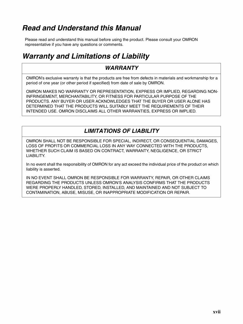
Read and Understand this ManualPlease read and understand this manual before using the product. Please consult your OMRON representative if you have any questions or comments.
Warranty and Limitations of Liability
WARRANTY
OMRON's exclusive warranty is that the products are free from defects in materials and workmanship for a period of one year (or other period if specified) from date of sale by OMRON.
OMRON MAKES NO WARRANTY OR REPRESENTATION, EXPRESS OR IMPLIED, REGARDING NON-INFRINGEMENT, MERCHANTABILITY, OR FITNESS FOR PARTICULAR PURPOSE OF THE PRODUCTS. ANY BUYER OR USER ACKNOWLEDGES THAT THE BUYER OR USER ALONE HAS DETERMINED THAT THE PRODUCTS WILL SUITABLY MEET THE REQUIREMENTS OF THEIR INTENDED USE. OMRON DISCLAIMS ALL OTHER WARRANTIES, EXPRESS OR IMPLIED.
LIMITATIONS OF LIABILITY
OMRON SHALL NOT BE RESPONSIBLE FOR SPECIAL, INDIRECT, OR CONSEQUENTIAL DAMAGES, LOSS OF PROFITS OR COMMERCIAL LOSS IN ANY WAY CONNECTED WITH THE PRODUCTS, WHETHER SUCH CLAIM IS BASED ON CONTRACT, WARRANTY, NEGLIGENCE, OR STRICT LIABILITY.
In no event shall the responsibility of OMRON for any act exceed the individual price of the product on which liability is asserted.
IN NO EVENT SHALL OMRON BE RESPONSIBLE FOR WARRANTY, REPAIR, OR OTHER CLAIMS REGARDING THE PRODUCTS UNLESS OMRON'S ANALYSIS CONFIRMS THAT THE PRODUCTS WERE PROPERLY HANDLED, STORED, INSTALLED, AND MAINTAINED AND NOT SUBJECT TO CONTAMINATION, ABUSE, MISUSE, OR INAPPROPRIATE MODIFICATION OR REPAIR.
xvii
Application Considerations
SUITABILITY FOR USE
OMRON shall not be responsible for conformity with any standards, codes, or regulations that apply to the combination of products in the customer's application or use of the products.
At the customer's request, OMRON will provide applicable third party certification documents identifying ratings and limitations of use that apply to the products. This information by itself is not sufficient for a complete determination of the suitability of the products in combination with the end product, machine, system, or other application or use.
The following are some examples of applications for which particular attention must be given. This is not intended to be an exhaustive list of all possible uses of the products, nor is it intended to imply that the uses listed may be suitable for the products:
• Outdoor use, uses involving potential chemical contamination or electrical interference, or conditions or uses not described in this manual.
• Nuclear energy control systems, combustion systems, railroad systems, aviation systems, medical equipment, amusement machines, vehicles, safety equipment, and installations subject to separate industry or government regulations.
• Systems, machines, and equipment that could present a risk to life or property.
Please know and observe all prohibitions of use applicable to the products.
NEVER USE THE PRODUCTS FOR AN APPLICATION INVOLVING SERIOUS RISK TO LIFE OR PROPERTY WITHOUT ENSURING THAT THE SYSTEM AS A WHOLE HAS BEEN DESIGNED TO ADDRESS THE RISKS, AND THAT THE OMRON PRODUCTS ARE PROPERLY RATED AND INSTALLED FOR THE INTENDED USE WITHIN THE OVERALL EQUIPMENT OR SYSTEM.
PROGRAMMABLE PRODUCTS
OMRON shall not be responsible for the user's programming of a programmable product, or any consequence thereof.
xviii
Disclaimers
CHANGE IN SPECIFICATIONS
Product specifications and accessories may be changed at any time based on improvements and other reasons.
It is our practice to change model numbers when published ratings or features are changed, or when significant construction changes are made. However, some specifications of the products may be changed without any notice. When in doubt, special model numbers may be assigned to fix or establish key specifications for your application on your request. Please consult with your OMRON representative at any time to confirm actual specifications of purchased products.
DIMENSIONS AND WEIGHTS
Dimensions and weights are nominal and are not to be used for manufacturing purposes, even when tolerances are shown.
PERFORMANCE DATA
Performance data given in this manual is provided as a guide for the user in determining suitability and does not constitute a warranty. It may represent the result of OMRON's test conditions, and the users must correlate it to actual application requirements. Actual performance is subject to the OMRON Warranty and Limitations of Liability.
ERRORS AND OMISSIONS
The information in this manual has been carefully checked and is believed to be accurate; however, no responsibility is assumed for clerical, typographical, or proofreading errors, or omissions.
xix

xx

SECTION 1Overview
This section describes the features of the CX-Designer and the startup procedures for NS-series PTs for first-time users.
1-1 Features of the CX-Designer. . . . . . . . . . . . . . . . . . . . . . . . . . . . . . . . . . . . . . 2
1-1-1 Features. . . . . . . . . . . . . . . . . . . . . . . . . . . . . . . . . . . . . . . . . . . . . . . 2
1-2 Basic Operation Procedures . . . . . . . . . . . . . . . . . . . . . . . . . . . . . . . . . . . . . . 5
1
Features of the CX-Designer Section 1-1
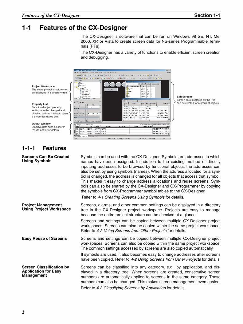
1-1 Features of the CX-DesignerThe CX-Designer is software that can be run on Windows 98 SE, NT, Me,2000, XP, or Vista to create screen data for NS-series Programmable Termi-nals (PTs).
The CX-Designer has a variety of functions to enable efficient screen creationand debugging.
1-1-1 FeaturesScreens Can Be Created Using Symbols
Symbols can be used with the CX-Designer. Symbols are addresses to whichnames have been assigned. In addition to the existing method of directlyinputting addresses to be browsed by functional objects, the addresses canalso be set by using symbols (names). When the address allocated for a sym-bol is changed, the address is changed for all objects that access that symbol.This makes it easy to change address allocations and reuse screens. Sym-bols can also be shared by the CX-Designer and CX-Programmer by copyingthe symbols from CX-Programmer symbol tables to the CX-Designer.
Refer to 4-1 Creating Screens Using Symbols for details.
Project Management Using Project Workspace
Screens, alarms, and other common settings can be displayed in a directorytree in the CX-Designer project workspace. Projects are easy to managebecause the entire project structure can be checked at a glance.
Screens and settings can be copied between multiple CX-Designer projectworkspaces. Screens can also be copied within the same project workspace.Refer to 4-2 Using Screens from Other Projects for details.
Easy Reuse of Screens Screens and settings can be copied between multiple CX-Designer projectworkspaces. Screens can also be copied within the same project workspace.The common settings accessed by screens are also copied automatically.
If symbols are used, it also becomes easy to change addresses after screenshave been copied. Refer to 4-2 Using Screens from Other Projects for details.
Screen Classification by Application for Easy Management
Screens can be classified into any category, e.g., by application, and dis-played in a directory tree. When screens are created, consecutive screennumbers are automatically applied to screens in the same category. Thesenumbers can also be changed. This makes screen management even easier.
Refer to 4-3 Classifying Screens by Application for details.
Project WorkspaceThe entire project structure can be displayed in a directory tree.
Property ListFunctional object property settings can be changed and checked without having to open a properties dialog box.
Output WindowDisplays data such as search results and error details.
Edit ScreensScreen data displayed on the PTs can be created for a group of objects.
2
Features of the CX-Designer Section 1-1
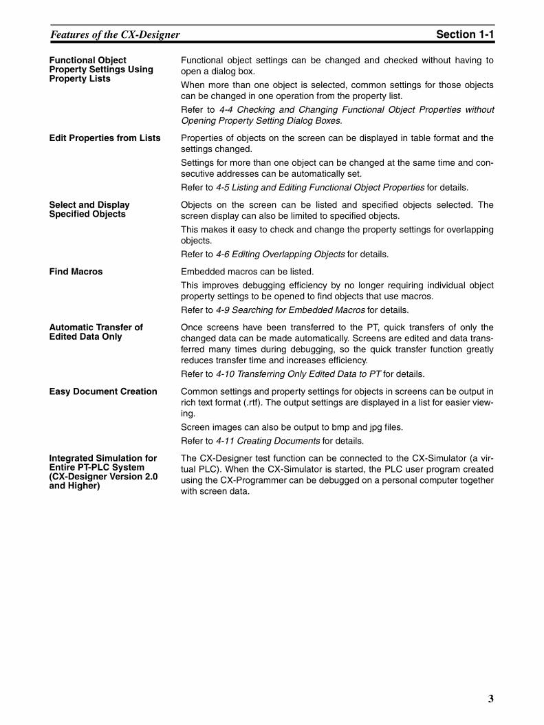
Functional Object Property Settings Using Property Lists
Functional object settings can be changed and checked without having toopen a dialog box.
When more than one object is selected, common settings for those objectscan be changed in one operation from the property list.
Refer to 4-4 Checking and Changing Functional Object Properties withoutOpening Property Setting Dialog Boxes.
Edit Properties from Lists Properties of objects on the screen can be displayed in table format and thesettings changed.
Settings for more than one object can be changed at the same time and con-secutive addresses can be automatically set.
Refer to 4-5 Listing and Editing Functional Object Properties for details.
Select and Display Specified Objects
Objects on the screen can be listed and specified objects selected. Thescreen display can also be limited to specified objects.
This makes it easy to check and change the property settings for overlappingobjects.
Refer to 4-6 Editing Overlapping Objects for details.
Find Macros Embedded macros can be listed.
This improves debugging efficiency by no longer requiring individual objectproperty settings to be opened to find objects that use macros.
Refer to 4-9 Searching for Embedded Macros for details.
Automatic Transfer of Edited Data Only
Once screens have been transferred to the PT, quick transfers of only thechanged data can be made automatically. Screens are edited and data trans-ferred many times during debugging, so the quick transfer function greatlyreduces transfer time and increases efficiency.
Refer to 4-10 Transferring Only Edited Data to PT for details.
Easy Document Creation Common settings and property settings for objects in screens can be output inrich text format (.rtf). The output settings are displayed in a list for easier view-ing.
Screen images can also be output to bmp and jpg files.
Refer to 4-11 Creating Documents for details.
Integrated Simulation for Entire PT-PLC System (CX-Designer Version 2.0 and Higher)
The CX-Designer test function can be connected to the CX-Simulator (a vir-tual PLC). When the CX-Simulator is started, the PLC user program createdusing the CX-Programmer can be debugged on a personal computer togetherwith screen data.
3
Features of the CX-Designer Section 1-1
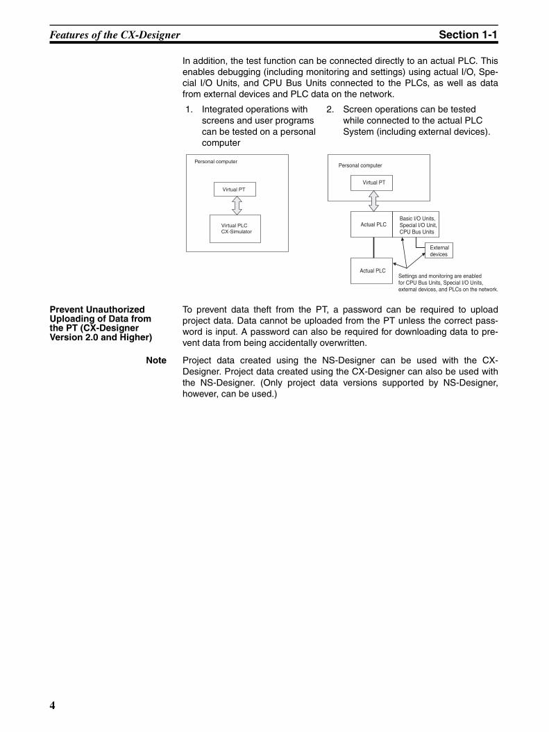
In addition, the test function can be connected directly to an actual PLC. Thisenables debugging (including monitoring and settings) using actual I/O, Spe-cial I/O Units, and CPU Bus Units connected to the PLCs, as well as datafrom external devices and PLC data on the network.
Prevent Unauthorized Uploading of Data from the PT (CX-Designer Version 2.0 and Higher)
To prevent data theft from the PT, a password can be required to uploadproject data. Data cannot be uploaded from the PT unless the correct pass-word is input. A password can also be required for downloading data to pre-vent data from being accidentally overwritten.
Note Project data created using the NS-Designer can be used with the CX-Designer. Project data created using the CX-Designer can also be used withthe NS-Designer. (Only project data versions supported by NS-Designer,however, can be used.)
1. Integrated operations with screens and user programs can be tested on a personal computer
2. Screen operations can be tested while connected to the actual PLC System (including external devices).
Personal computer
Virtual PT
Virtual PLC CX-Simulator
Personal computer
Virtual PT
Actual PLCBasic I/O Units, Special I/O Unit, CPU Bus Units
External devices
Actual PLCSettings and monitoring are enabled for CPU Bus Units, Special I/O Units, external devices, and PLCs on the network.
4
Basic Operation Procedures Section 1-2
1-2 Basic Operation ProceduresThis section describes the basic procedures for creating screens using CX-Designer, transferring data to the PT, and displaying screens. Refer to the CX-Designer online help and the NS Series Setup Manual and NS Series Pro-gramming Manual for details.
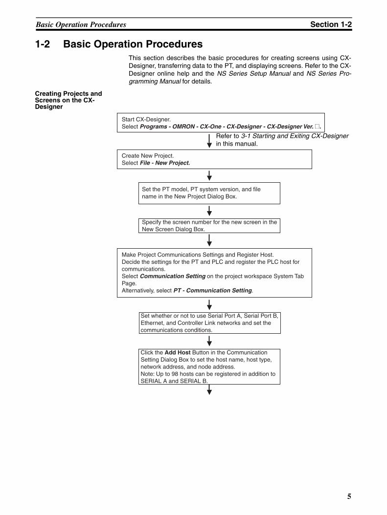
Creating Projects and Screens on the CX-Designer
Start CX-Designer.Select Programs - OMRON - CX-One - CX-Designer - CX-Designer Ver. @.
Make Project Communications Settings and Register Host. Decide the settings for the PT and PLC and register the PLC host for communications. Select Communication Setting on the project workspace System Tab Page. Alternatively, select PT - Communication Setting.
Create New Project. Select File - New Project.
Set the PT model, PT system version, and file name in the New Project Dialog Box.
Specify the screen number for the new screen in the New Screen Dialog Box.
Set whether or not to use Serial Port A, Serial Port B, Ethernet, and Controller Link networks and set the communications conditions.
Click the Add Host Button in the Communication Setting Dialog Box to set the host name, host type, network address, and node address. Note: Up to 98 hosts can be registered in addition to SERIAL A and SERIAL B.
Refer to 3-1 Starting and Exiting CX-Designerin this manual.
5
Basic Operation Procedures Section 1-2
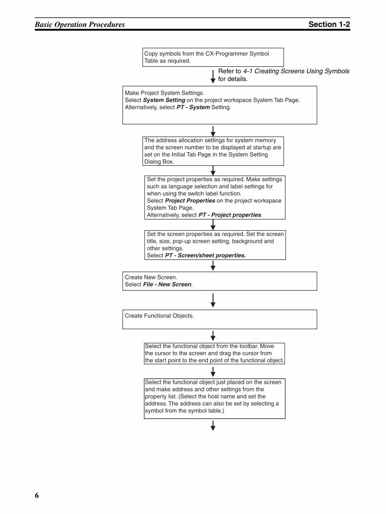
Copy symbols from the CX-Programmer Symbol Table as required.
Make Project System Settings. Select System Setting on the project workspace System Tab Page. Alternatively, select PT - System Setting.
The address allocation settings for system memory and the screen number to be displayed at startup are set on the Initial Tab Page in the System Setting Dialog Box.
Set the project properties as required. Make settings such as language selection and label settings for when using the switch label function. Select Project Properties on the project workspace System Tab Page. Alternatively, select PT - Project properties.
Set the screen properties as required. Set the screen title, size, pop-up screen setting, background and other settings. Select PT - Screen/sheet properties.
Create New Screen. Select File - New Screen.
Create Functional Objects.
Select the functional object from the toolbar. Move the cursor to the screen and drag the cursor from the start point to the end point of the functional object.
Select the functional object just placed on the screen and make address and other settings from the property list. (Select the host name and set the address. The address can also be set by selecting a symbol from the symbol table.)
Refer to 4-1 Creating Screens Using Symbolsfor details.
6
Basic Operation Procedures Section 1-2
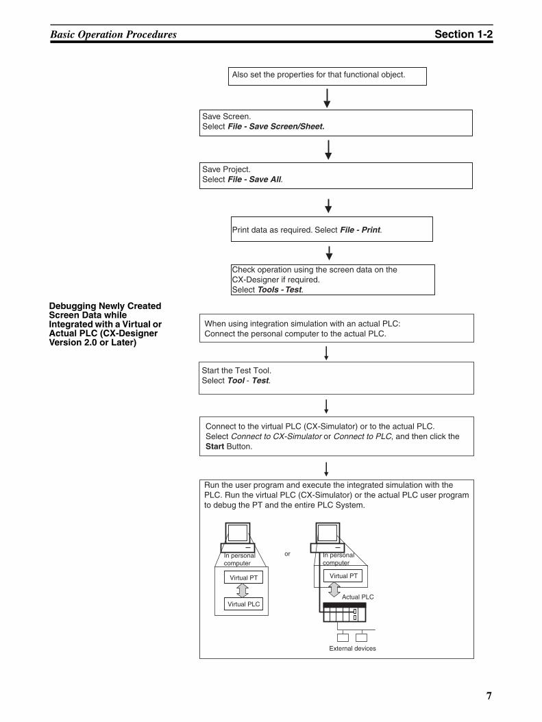
Debugging Newly Created Screen Data while Integrated with a Virtual or Actual PLC (CX-Designer Version 2.0 or Later)
Also set the properties for that functional object.
Save Screen. Select File - Save Screen/Sheet.
Save Project.Select File - Save All.
Print data as required. Select File - Print.
Check operation using the screen data on the CX-Designer if required. Select Tools - Test.
When using integration simulation with an actual PLC:Connect the personal computer to the actual PLC.
Start the Test Tool.Select Tool - Test.
Connect to the virtual PLC (CX-Simulator) or to the actual PLC.Select Connect to CX-Simulator or Connect to PLC, and then click the Start Button.
Run the user program and execute the integrated simulation with the PLC. Run the virtual PLC (CX-Simulator) or the actual PLC user program to debug the PT and the entire PLC System.
In personal computer
Virtual PT
Virtual PLC
or In personal computer
Virtual PT
Actual PLC
External devices
7
Basic Operation Procedures Section 1-2
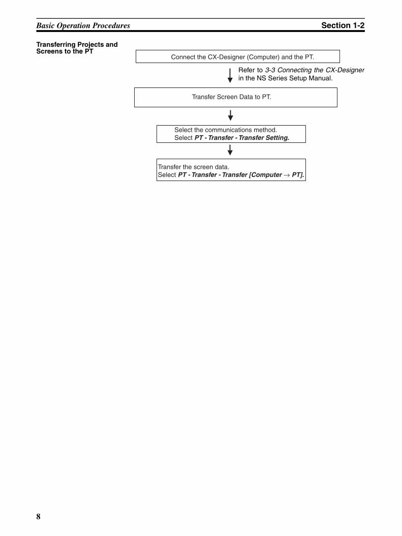
Transferring Projects and Screens to the PT
Connect the CX-Designer (Computer) and the PT.
Transfer Screen Data to PT.
Select the communications method. Select PT - Transfer - Transfer Setting.
Transfer the screen data. Select PT - Transfer - Transfer [Computer → PT].
Refer to 3-3 Connecting the CX-Designerin the NS Series Setup Manual.
8
Basic Operation Procedures Section 1-2
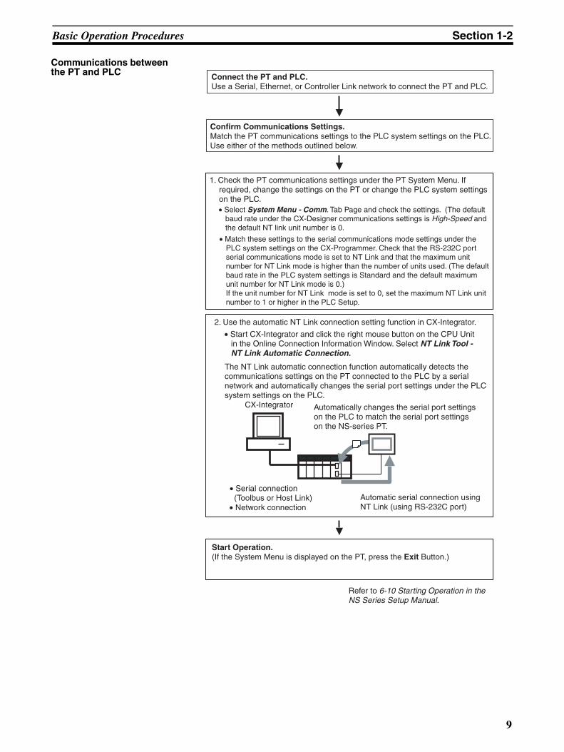
Communications between the PT and PLC
Connect the PT and PLC. Use a Serial, Ethernet, or Controller Link network to connect the PT and PLC.
2. Use the automatic NT Link connection setting function in CX-Integrator.
• Serial connection (Toolbus or Host Link)• Network connection
Automatic serial connection using NT Link (using RS-232C port)
Start Operation. (If the System Menu is displayed on the PT, press the Exit Button.)
CX-Integrator
Confirm Communications Settings. Match the PT communications settings to the PLC system settings on the PLC. Use either of the methods outlined below.
1. Check the PT communications settings under the PT System Menu. If required, change the settings on the PT or change the PLC system settings on the PLC. • Select System Menu - Comm. Tab Page and check the settings. (The default
baud rate under the CX-Designer communications settings is High-Speed and the default NT link unit number is 0.
• Match these settings to the serial communications mode settings under the PLC system settings on the CX-Programmer. Check that the RS-232C port serial communications mode is set to NT Link and that the maximum unit number for NT Link mode is higher than the number of units used. (The default baud rate in the PLC system settings is Standard and the default maximum unit number for NT Link mode is 0.) If the unit number for NT Link mode is set to 0, set the maximum NT Link unit number to 1 or higher in the PLC Setup.
Refer to 6-10 Starting Operation in the NS Series Setup Manual.
Automatically changes the serial port settings on the PLC to match the serial port settings on the NS-series PT.
• Start CX-Integrator and click the right mouse button on the CPU Unit in the Online Connection Information Window. Select NT Link Tool - NT Link Automatic Connection.
The NT Link automatic connection function automatically detects the communications settings on the PT connected to the PLC by a serial network and automatically changes the serial port settings under the PLC system settings on the PLC.
9

Basic Operation Procedures Section 1-2
10
SECTION 2Setting Up the CX-Designer
The CX-Designer must be installed on the computer before it can be used for the first time. The CX-Designer is applicationsoftware that runs on a Windows 98 SE, NT, Me, 2000, XP, or Vista operating system. This section describes how to installthe CX-Designer assuming that the Windows 98 SE, NT, Me, 2000, XP, or Vista operating system has already been installedon the computer.
2-1 Preparations for Installation . . . . . . . . . . . . . . . . . . . . . . . . . . . . . . . . . . . . . . 12
2-2 Installing the CX-Designer . . . . . . . . . . . . . . . . . . . . . . . . . . . . . . . . . . . . . . . 13
2-3 Uninstalling . . . . . . . . . . . . . . . . . . . . . . . . . . . . . . . . . . . . . . . . . . . . . . . . . . . 18
2-4 Installing USB Drivers for NS-Series PTs. . . . . . . . . . . . . . . . . . . . . . . . . . . . 18
11
Preparations for Installation Section 2-1
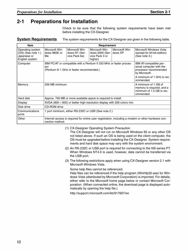
2-1 Preparations for InstallationCheck to be sure that the following system requirements have been metbefore installing the CX-Designer.
System Requirements The system requirements for the CX-Designer are given in the following table.
(1) CX-Designer Operating System PrecautionThe CX-Designer will not run on Microsoft Windows 95 or any other OSnot listed above. If such an OS is being used on the client computer, theOS must be upgraded before installing the CX-Designer. System require-ments and hard disk space may vary with the system environment.
(2) An RS-232C or USB port is required for connecting to the NS-series PT.When Windows NT4.0 is used, however, data cannot be transferred viathe USB port.
(3) The following restrictions apply when using CX-Designer version 2.1 withMicrosoft Windows Vista.
Some help files cannot be referenced.Help files can be referenced if the help program (WinHlp32.exe) for Win-dows Vista (distributed by Microsoft Corporation) is imported. For details,either refer to the Microsoft home page below or contact Microsoft Cor-poration. (When connected online, the download page is displayed auto-matically by opening the help file.)
http://support.microsoft.com/kb/917607/en
Item Requirement
Operating system (OS) (See note 1.) Japanese or English system
Microsoft Win-dows 98SE or Me
Microsoft Win-dows NT (Ser-vice Pack 6a)
Microsoft Win-dows 2000 (Ser-vice Pack 3 or higher)
Microsoft Win-dows XP
Microsoft Windows Vista (except for 64-bit edition) (See note 3.)
Computer IBM PC/AT or compatible with a Pentium II 333 MHz or faster proces-sor (Pentium III 1 GHz or faster recommended.)
IBM AT-compatible per-sonal computer with the processor recommended by Microsoft.A minimum of 1 GHz is rec-ommended.
Memory 256 MB minimum A minimum of 1 GB of memory is required, and a minimum of 1.5 GB is rec-ommended.
Hard disk Approx. 700 MB or more available space is required to install.
Display SVGA (800 × 600) or better high-resolution display with 256 colors min.
Disk drive CD-ROM drive
Communications ports
1 port minimum, either RS-232C or USB (See note 2.)
Other Internet access is required for online user registration, including a modem or other hardware con-nection method.
12
Installing the CX-Designer Section 2-2
Using CX-Designer with Windows Vista
The following restrictions apply when using CX-Designer with Windows Vista.
2-2 Installing the CX-DesignerInstall the CX-Designer in the hard disk.
To install the CX-Designer, execute the installation program provided.
For details on procedures for installing the CX-Designer from CX-One FA Inte-grated Tool Package, refer to the CX-One Ver. 2.1 Setup Manual provided withCX-One.
Note If the CX-Designer was previously installed from the CX-One and it's neces-sary to install it from the individual CX-Designer CD-ROM, always uninstallthe CX-Designer using the following procedure before installing it from its indi-vidual CD-ROM. The CX-Designer will not operate properly if it is installedwithout first uninstalling it.
1,2,3... 1. Insert the CX-One installation disk 1 into the CD-ROM drive.
2. Select the Modify Option to enable modifying the Support Software that isinstalled.
3. In the Select Features Dialog Box, clear the selection of only the CX-De-signer. Do not change any other selections.
4. Continue by following the instructions in the dialog boxes to modify the in-stallation and uninstall CX-Designer.
5. Once the CX-Designer uninstallation process has been completed, placethe individual CD-ROM disk for the CX-Designer into the CD-ROM driveand install the CX-Designer. (See note.)
Note If the version of the CX-Server bundled on the individual CX-De-signer CD-ROM is lower than the version of the CX-Server bundledwith the CX-One, install only the CX-Designer and NOT the CX-Server. If a version of CX-Server that is lower than the version withthe CX-One is installed, the CX-One will not operate properly.
The main buttons that are displayed during installation are as follows:
Item Contents
Fonts When project data created outside of Windows Vista is saved in Windows Vista, characters using fonts that are different in Windows Vista will be changed.Similarly, characters in project data using fonts added or changed in Windows Vista will be changed when saved outside of Windows Vista.
Memory Card Transfer Support Software
Two-bytes characters used in file names and folder names on the Memory Card will not be displayed nor-mally.
Cat. No. Model Manual name Contents
W463 CXONE-AL@@C-EV2/AL@@D-EV2
CX-One Ver. 2.1 Setup Manual
Installation and overview of CX-One FA Integrated Tool Package.
Confirms the settings in the window displayed and moves to the next window.
Cancels the settings in the window displayed and returns to the previ-ous window.
13
Installing the CX-Designer Section 2-2
Installation Procedure
1,2,3... 1. Start up Windows 98SE, NT, Me, 2000, XP, or Vista.
2. Close all applications before executing installation. Place the CX-DesignerCD-ROM in the CD-ROM drive. The setup program is started automatical-ly. If the setup program does not start automatically, such as after execut-ing uninstall, locate Setup.exe in the CD-ROM using Windows Explorer,and then double-click the file to execute the setup program.
Note If CX-Designer is already installed, a dialog box to confirm deletion of this ver-sion will be displayed. Click the OK Button to start deleting this version. To exitthe setup program, click the Cancel Button and then click the Exit Button. Fin-sGateway and CX-Server will not be uninstalled by this operation.
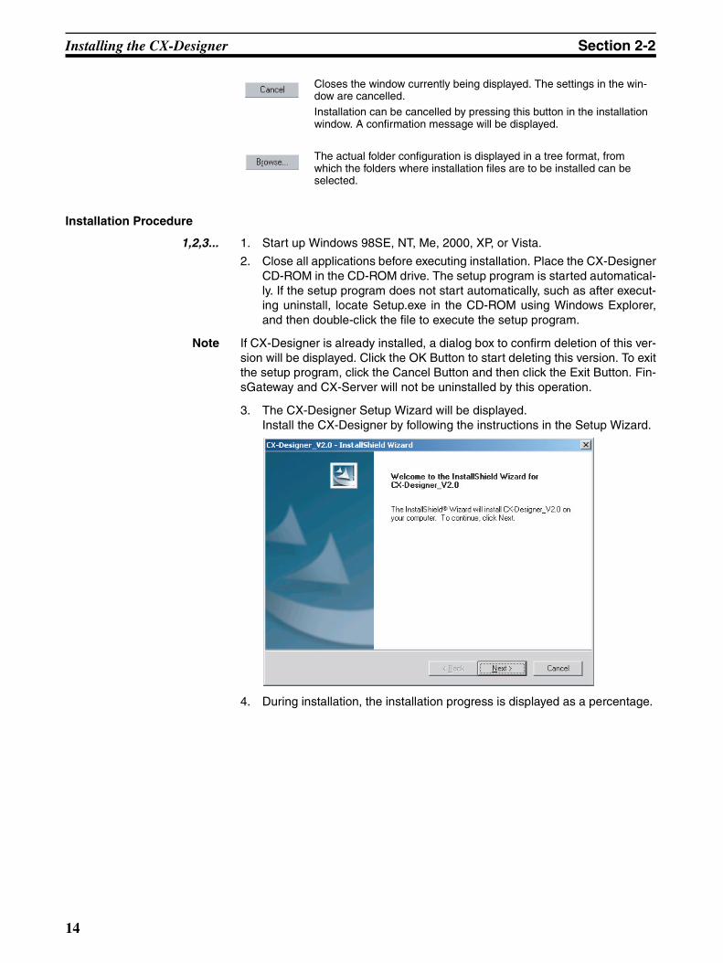
3. The CX-Designer Setup Wizard will be displayed. Install the CX-Designer by following the instructions in the Setup Wizard.
4. During installation, the installation progress is displayed as a percentage.
Closes the window currently being displayed. The settings in the win-dow are cancelled. Installation can be cancelled by pressing this button in the installation window. A confirmation message will be displayed.
The actual folder configuration is displayed in a tree format, from which the folders where installation files are to be installed can be selected.
14
Installing the CX-Designer Section 2-2
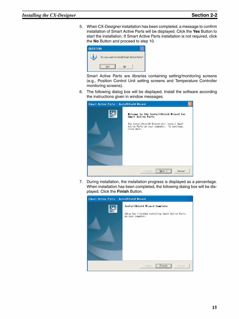
5. When CX-Designer installation has been completed, a message to confirminstallation of Smart Active Parts will be displayed. Click the Yes Button tostart the installation. If Smart Active Parts installation is not required, clickthe No Button and proceed to step 10.
Smart Active Parts are libraries containing setting/monitoring screens(e.g., Position Control Unit setting screens and Temperature Controllermonitoring screens).
6. The following dialog box will be displayed. Install the software accordingthe instructions given in window messages.
7. During installation, the installation progress is displayed as a percentage.When installation has been completed, the following dialog box will be dis-played. Click the Finish Button.
15
Installing the CX-Designer Section 2-2
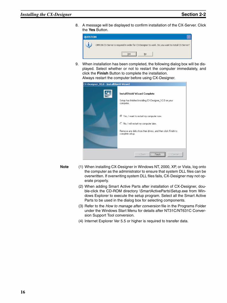
8. A message will be displayed to confirm installation of the CX-Server. Clickthe Yes Button.
9. When installation has been completed, the following dialog box will be dis-played. Select whether or not to restart the computer immediately, andclick the Finish Button to complete the installation. Always restart the computer before using CX-Designer.
Note (1) When installing CX-Designer in Windows NT, 2000, XP, or Vista, log ontothe computer as the administrator to ensure that system DLL files can beoverwritten. If overwriting system DLL files fails, CX-Designer may not op-erate properly.
(2) When adding Smart Active Parts after installation of CX-Designer, dou-ble-click the CD-ROM directory \SmartActiveParts\Setup.exe from Win-dows Explorer to execute the setup program. Select all the Smart ActiveParts to be used in the dialog box for selecting components.
(3) Refer to the How to manage after conversion file in the Programs Folderunder the Windows Start Menu for details after NT31C/NT631C Conver-sion Support Tool conversion.
(4) Internet Explorer Ver 5.5 or higher is required to transfer data.
16
Installing the CX-Designer Section 2-2
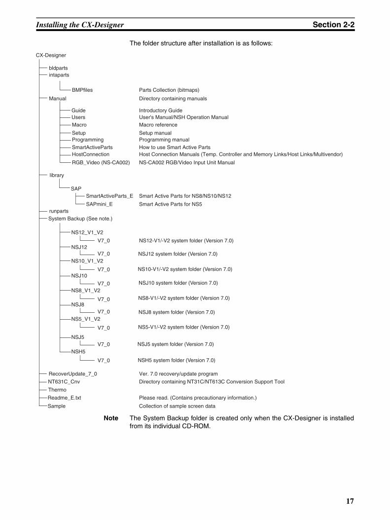
The folder structure after installation is as follows:
Note The System Backup folder is created only when the CX-Designer is installedfrom its individual CD-ROM.
SmartActiveParts
CX-Designer
bldpartsintaparts
BMPfiles
Manual
Macro
SetupProgramming
HostConnection
RGB_Video (NS-CA002)
SAPSmartActiveParts_E
SAPmini_ErunpartsSystem Backup (See note.)
NS12_V1_V2
NSJ12
NS10_V1_V2
NSJ10
NS8_V1_V2
NSJ8
NS5_V1_V2
V7_0
V7_0
V7_0
V7_0
V7_0
V7_0
V7_0
RecoverUpdate_7_0
NT631C_Cnv
Readme_E.txt
Parts Collection (bitmaps)
Directory containing manuals
Macro reference
Setup manualProgramming manual
How to use Smart Active Parts Host Connection Manuals (Temp. Controller and Memory Links/Host Links/Multivendor)
Smart Active Parts for NS8/NS10/NS12
NS-CA002 RGB/Video Input Unit Manual
Smart Active Parts for NS5
NS12-V1/-V2 system folder (Version 7.0)
Ver. 7.0 recovery/update program
Directory containing NT31C/NT613C Conversion Support Tool
Please read. (Contains precautionary information.)
GuideUsers
Introductory GuideUser's Manual/NSH Operation Manual
library
Thermo
NSJ5
NSH5V7_0
V7_0
NSJ12 system folder (Version 7.0)
NS10-V1/-V2 system folder (Version 7.0)
NSJ10 system folder (Version 7.0)
NS8-V1/-V2 system folder (Version 7.0)
NSJ8 system folder (Version 7.0)
NS5-V1/-V2 system folder (Version 7.0)
NSJ5 system folder (Version 7.0)
NSH5 system folder (Version 7.0)
Sample Collection of sample screen data
17
Uninstalling Section 2-3
2-3 Uninstalling Operation Procedure
1,2,3... 1. To uninstall the CX-Designer, click the Windows Start Button and selectSettings - Control Panel.
2. Double-click Add/Remove Applications.
3. Select CX-Designer_V2.1 from the list and click the Edit/Delete Button.Follow the instructions displayed in window messages to uninstall the CX-Designer.
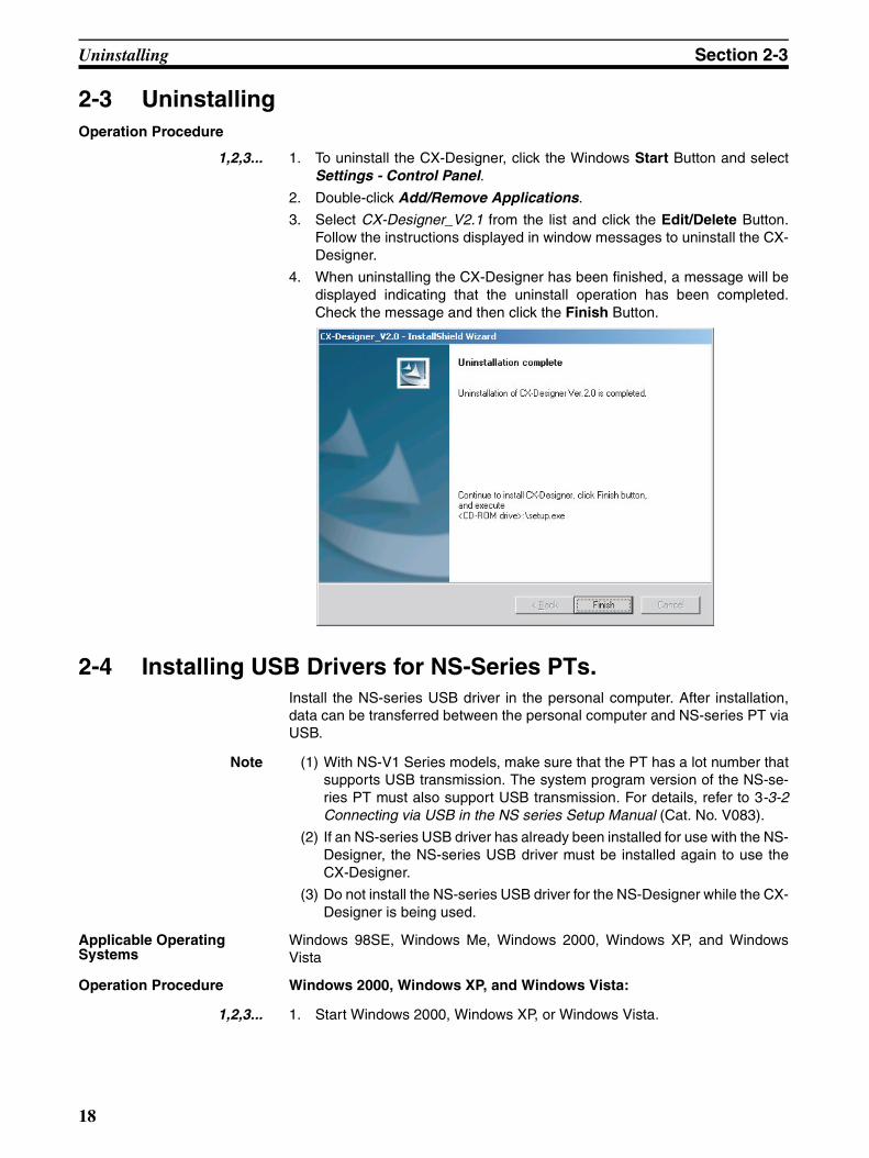
4. When uninstalling the CX-Designer has been finished, a message will bedisplayed indicating that the uninstall operation has been completed.Check the message and then click the Finish Button.
2-4 Installing USB Drivers for NS-Series PTs.Install the NS-series USB driver in the personal computer. After installation,data can be transferred between the personal computer and NS-series PT viaUSB.
Note (1) With NS-V1 Series models, make sure that the PT has a lot number thatsupports USB transmission. The system program version of the NS-se-ries PT must also support USB transmission. For details, refer to 3-3-2Connecting via USB in the NS series Setup Manual (Cat. No. V083).
(2) If an NS-series USB driver has already been installed for use with the NS-Designer, the NS-series USB driver must be installed again to use theCX-Designer.
(3) Do not install the NS-series USB driver for the NS-Designer while the CX-Designer is being used.
Applicable Operating Systems
Windows 98SE, Windows Me, Windows 2000, Windows XP, and WindowsVista
Operation Procedure Windows 2000, Windows XP, and Windows Vista:
1,2,3... 1. Start Windows 2000, Windows XP, or Windows Vista.
18
Installing USB Drivers for NS-Series PTs. Section 2-4
2. Connect the personal computer to the NS-series PT USB slave connectorusing the USB cable. The following Found New Hardware Wizard will bedisplayed.
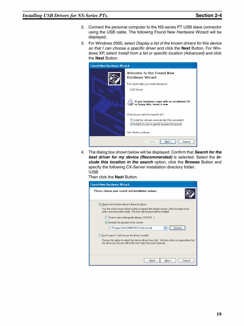
3. For Windows 2000, select Display a list of the known drivers for this deviceso that I can choose a specific driver and click the Next Button. For Win-dows XP, select Install from a list or specific location (Advanced) and clickthe Next Button.
4. The dialog box shown below will be displayed. Confirm that Search for thebest driver for my device (Recommended) is selected. Select the In-clude this location in the search option, click the Browse Button andspecify the following CX-Server installation directory folder:\USBThen click the Next Button.
19
Installing USB Drivers for NS-Series PTs. Section 2-4
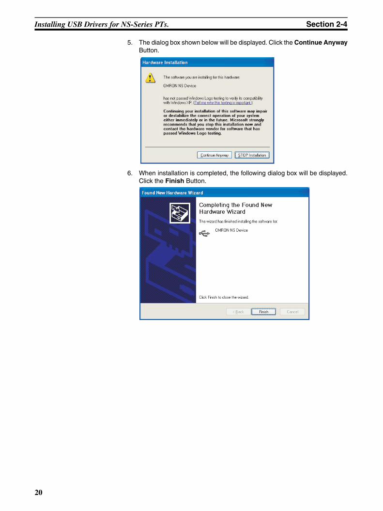
5. The dialog box shown below will be displayed. Click the Continue AnywayButton.
6. When installation is completed, the following dialog box will be displayed.Click the Finish Button.
20
Installing USB Drivers for NS-Series PTs. Section 2-4
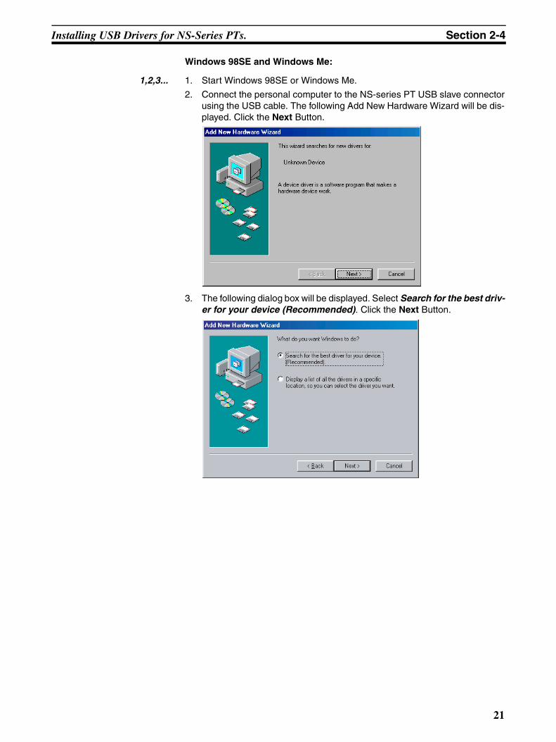
Windows 98SE and Windows Me:
1,2,3... 1. Start Windows 98SE or Windows Me.
2. Connect the personal computer to the NS-series PT USB slave connectorusing the USB cable. The following Add New Hardware Wizard will be dis-played. Click the Next Button.
3. The following dialog box will be displayed. Select Search for the best driv-er for your device (Recommended). Click the Next Button.
21
Installing USB Drivers for NS-Series PTs. Section 2-4
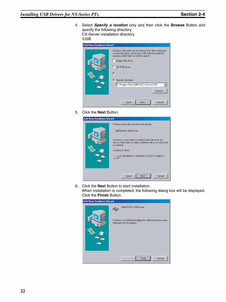
4. Select Specify a location only and then click the Browse Button andspecify the following directory.CX-Server installation directory\USB
5. Click the Next Button.
6. Click the Next Button to start installation.When installation is completed, the following dialog box will be displayed.Click the Finish Button.
22
Installing USB Drivers for NS-Series PTs. Section 2-4
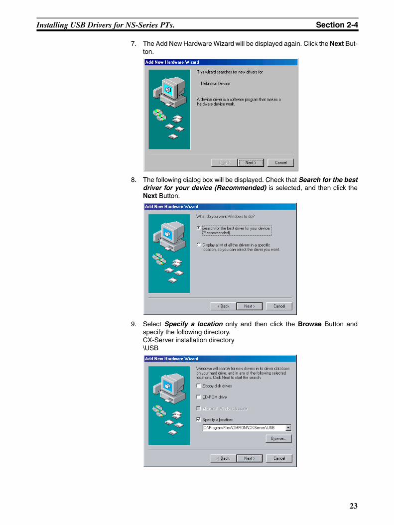
7. The Add New Hardware Wizard will be displayed again. Click the Next But-ton.
8. The following dialog box will be displayed. Check that Search for the bestdriver for your device (Recommended) is selected, and then click theNext Button.
9. Select Specify a location only and then click the Browse Button andspecify the following directory.CX-Server installation directory\USB
23
Installing USB Drivers for NS-Series PTs. Section 2-4
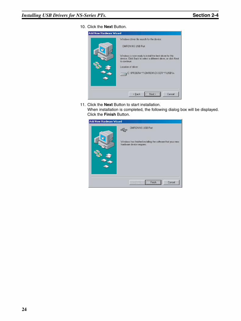
10. Click the Next Button.
11. Click the Next Button to start installation.When installation is completed, the following dialog box will be displayed.Click the Finish Button.
24
SECTION 3Basic Operations of the CX-Designer
This section describes basic functions and operation methods, such as starting and exiting CX-Designer and the userinterface.
3-1 Starting and Exiting CX-Designer . . . . . . . . . . . . . . . . . . . . . . . . . . . . . . . . . 26
3-1-1 Startup Method . . . . . . . . . . . . . . . . . . . . . . . . . . . . . . . . . . . . . . . . . 26
3-1-2 Exiting CX-Designer . . . . . . . . . . . . . . . . . . . . . . . . . . . . . . . . . . . . 26
3-2 Menu Commands . . . . . . . . . . . . . . . . . . . . . . . . . . . . . . . . . . . . . . . . . . . . . . 27
3-3 User Interface . . . . . . . . . . . . . . . . . . . . . . . . . . . . . . . . . . . . . . . . . . . . . . . . . 34
3-3-1 Names of Basic Screen Components . . . . . . . . . . . . . . . . . . . . . . . . 34
3-3-2 CX-Designer Functions and Screens . . . . . . . . . . . . . . . . . . . . . . . . 41
25
Starting and Exiting CX-Designer Section 3-1
3-1 Starting and Exiting CX-DesignerThis section describes how to start and exit the CX-Designer.
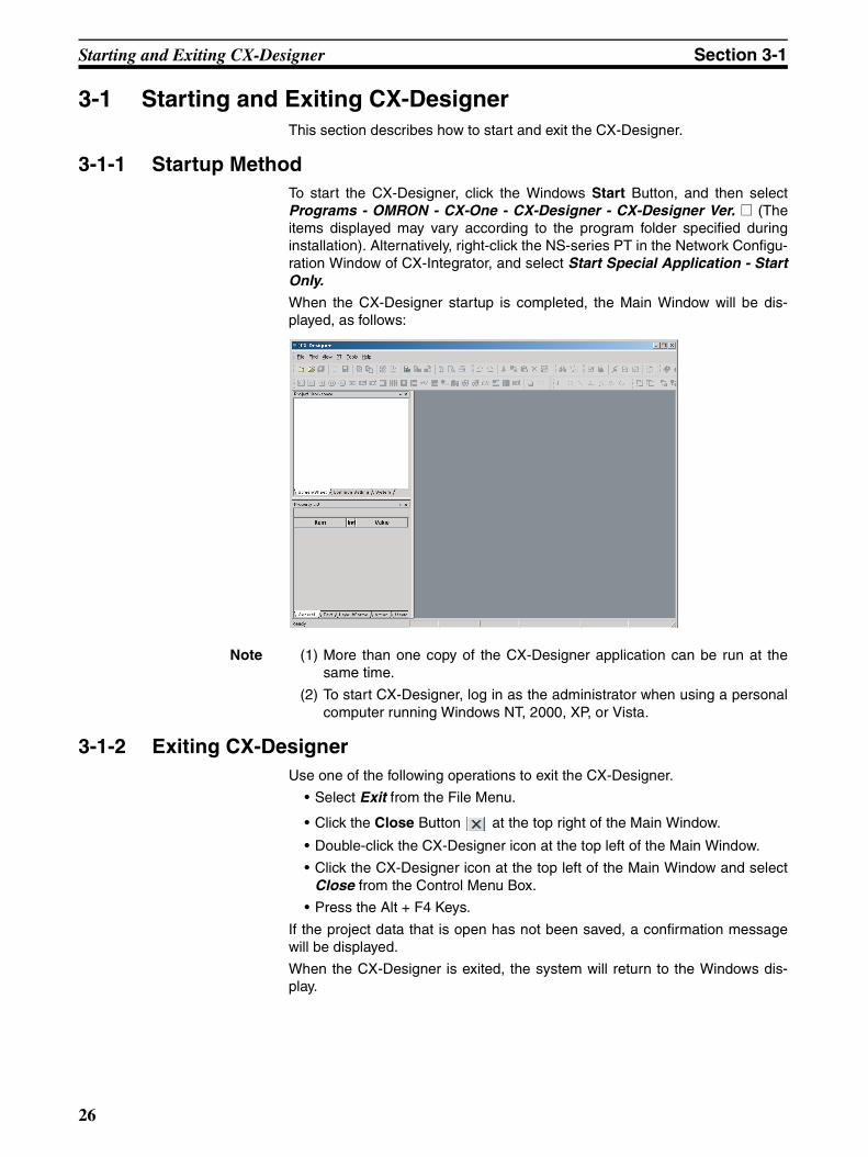
3-1-1 Startup MethodTo start the CX-Designer, click the Windows Start Button, and then selectPrograms - OMRON - CX-One - CX-Designer - CX-Designer Ver. @ (Theitems displayed may vary according to the program folder specified duringinstallation). Alternatively, right-click the NS-series PT in the Network Configu-ration Window of CX-Integrator, and select Start Special Application - StartOnly.
When the CX-Designer startup is completed, the Main Window will be dis-played, as follows:
Note (1) More than one copy of the CX-Designer application can be run at thesame time.
(2) To start CX-Designer, log in as the administrator when using a personalcomputer running Windows NT, 2000, XP, or Vista.
3-1-2 Exiting CX-DesignerUse one of the following operations to exit the CX-Designer.
• Select Exit from the File Menu.
• Click the Close Button at the top right of the Main Window.
• Double-click the CX-Designer icon at the top left of the Main Window.
• Click the CX-Designer icon at the top left of the Main Window and selectClose from the Control Menu Box.
• Press the Alt + F4 Keys.
If the project data that is open has not been saved, a confirmation messagewill be displayed.
When the CX-Designer is exited, the system will return to the Windows dis-play.
26
Menu Commands Section 3-2
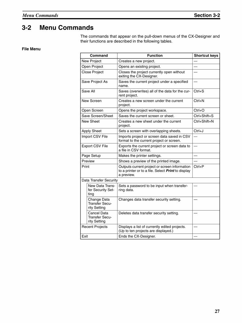
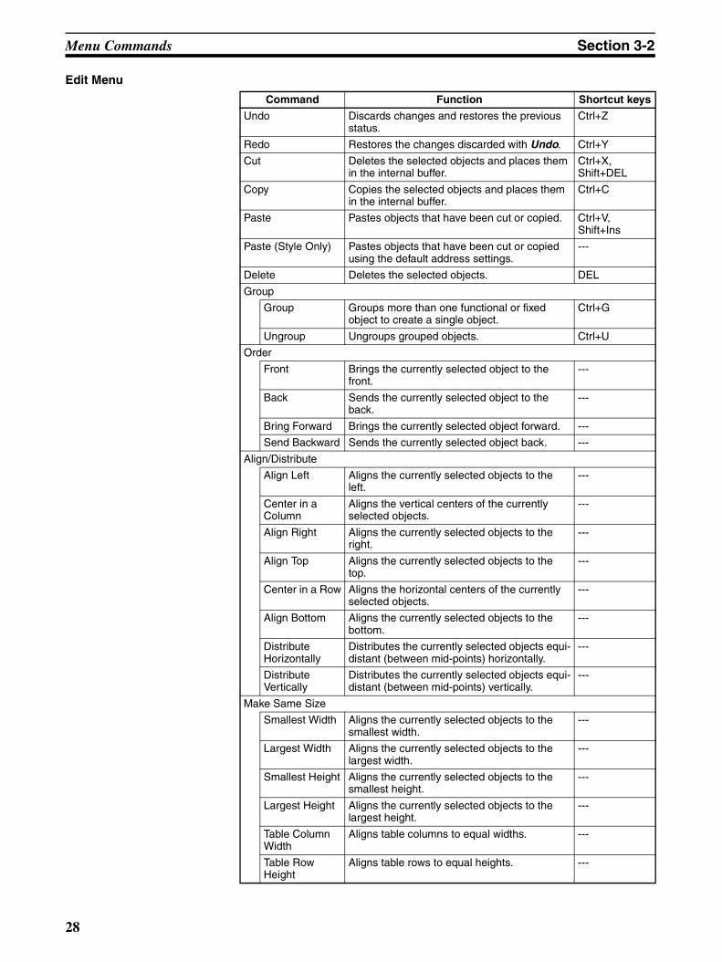
3-2 Menu CommandsThe commands that appear on the pull-down menus of the CX-Designer andtheir functions are described in the following tables.
File Menu
Command Function Shortcut keys
New Project Creates a new project. ---
Open Project Opens an existing project. ---
Close Project Closes the project currently open without exiting the CX-Designer.
---
Save Project As Saves the current project under a specified name.
---
Save All Saves (overwrites) all of the data for the cur-rent project.
Ctrl+S
New Screen Creates a new screen under the current project.
Ctrl+N
Open Screen Opens the project workspace. Ctrl+O
Save Screen/Sheet Saves the current screen or sheet. Ctrl+Shift+S
New Sheet Creates a new sheet under the current project.
Ctrl+Shift+N
Apply Sheet Sets a screen with overlapping sheets. Ctrl+J
Import CSV File Imports project or screen data saved in CSV format to the current project or screen.
---
Export CSV File Exports the current project or screen data to a file in CSV format.
---
Page Setup Makes the printer settings. ---
Preview Shows a preview of the printed image. ---
Print Outputs current project or screen information to a printer or to a file. Select Print to display a preview.
Ctrl+P
Data Transfer Security
New Data Trans-fer Security Set-ting
Sets a password to be input when transfer-ring data.
---
Change Data Transfer Secu-rity Setting
Changes data transfer security setting. ---
Cancel Data Transfer Secu-rity Setting
Deletes data transfer security setting. ---
Recent Projects Displays a list of currently edited projects. (Up to ten projects are displayed.)
---
Exit Ends the CX-Designer. ---
27
Menu Commands Section 3-2
Edit Menu
Command Function Shortcut keys
Undo Discards changes and restores the previous status.
Ctrl+Z
Redo Restores the changes discarded with Undo. Ctrl+Y
Cut Deletes the selected objects and places them in the internal buffer.
Ctrl+X, Shift+DEL
Copy Copies the selected objects and places them in the internal buffer.
Ctrl+C
Paste Pastes objects that have been cut or copied. Ctrl+V, Shift+Ins
Paste (Style Only) Pastes objects that have been cut or copied using the default address settings.
---
Delete Deletes the selected objects. DEL
Group
Group Groups more than one functional or fixed object to create a single object.
Ctrl+G
Ungroup Ungroups grouped objects. Ctrl+U
Order
Front Brings the currently selected object to the front.
---
Back Sends the currently selected object to the back.
---
Bring Forward Brings the currently selected object forward. ---
Send Backward Sends the currently selected object back. ---
Align/Distribute
Align Left Aligns the currently selected objects to the left.
---
Center in a Column
Aligns the vertical centers of the currently selected objects.
---
Align Right Aligns the currently selected objects to the right.
---
Align Top Aligns the currently selected objects to the top.
---
Center in a Row Aligns the horizontal centers of the currently selected objects.
---
Align Bottom Aligns the currently selected objects to the bottom.
---
Distribute Horizontally
Distributes the currently selected objects equi-distant (between mid-points) horizontally.
---
Distribute Vertically
Distributes the currently selected objects equi-distant (between mid-points) vertically.
---
Make Same Size
Smallest Width Aligns the currently selected objects to the smallest width.
---
Largest Width Aligns the currently selected objects to the largest width.
---
Smallest Height Aligns the currently selected objects to the smallest height.
---
Largest Height Aligns the currently selected objects to the largest height.
---
Table Column Width
Aligns table columns to equal widths. ---
Table Row Height
Aligns table rows to equal heights. ---
28
Menu Commands Section 3-2
Find Menu
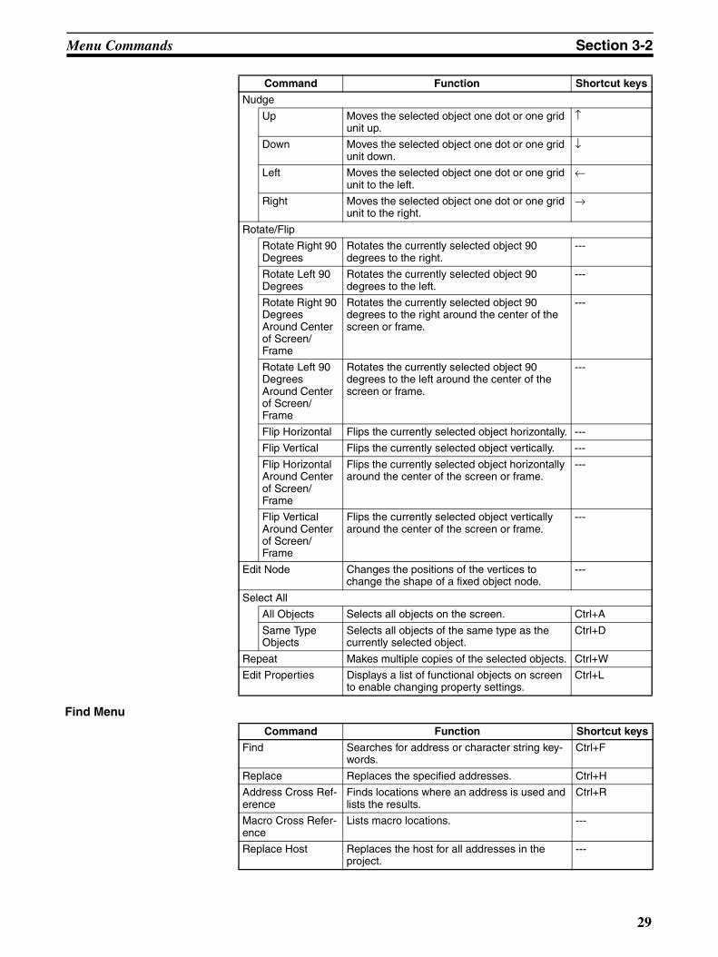
Nudge
Up Moves the selected object one dot or one grid unit up.
↑
Down Moves the selected object one dot or one grid unit down.
↓
Left Moves the selected object one dot or one grid unit to the left.
←
Right Moves the selected object one dot or one grid unit to the right.
→
Rotate/Flip
Rotate Right 90 Degrees
Rotates the currently selected object 90 degrees to the right.
---
Rotate Left 90 Degrees
Rotates the currently selected object 90 degrees to the left.
---
Rotate Right 90 Degrees Around Center of Screen/Frame
Rotates the currently selected object 90 degrees to the right around the center of the screen or frame.
---
Rotate Left 90 Degrees Around Center of Screen/Frame
Rotates the currently selected object 90 degrees to the left around the center of the screen or frame.
---
Flip Horizontal Flips the currently selected object horizontally. ---
Flip Vertical Flips the currently selected object vertically. ---
Flip Horizontal Around Center of Screen/Frame
Flips the currently selected object horizontally around the center of the screen or frame.
---
Flip Vertical Around Center of Screen/Frame
Flips the currently selected object vertically around the center of the screen or frame.
---
Edit Node Changes the positions of the vertices to change the shape of a fixed object node.
---
Select All
All Objects Selects all objects on the screen. Ctrl+A
Same Type Objects
Selects all objects of the same type as the currently selected object.
Ctrl+D
Repeat Makes multiple copies of the selected objects. Ctrl+W
Edit Properties Displays a list of functional objects on screen to enable changing property settings.
Ctrl+L
Command Function Shortcut keys
Command Function Shortcut keys
Find Searches for address or character string key-words.
Ctrl+F
Replace Replaces the specified addresses. Ctrl+H
Address Cross Ref-erence
Finds locations where an address is used and lists the results.
Ctrl+R
Macro Cross Refer-ence
Lists macro locations. ---
Replace Host Replaces the host for all addresses in the project.
---
29
Menu Commands Section 3-2
View Menu
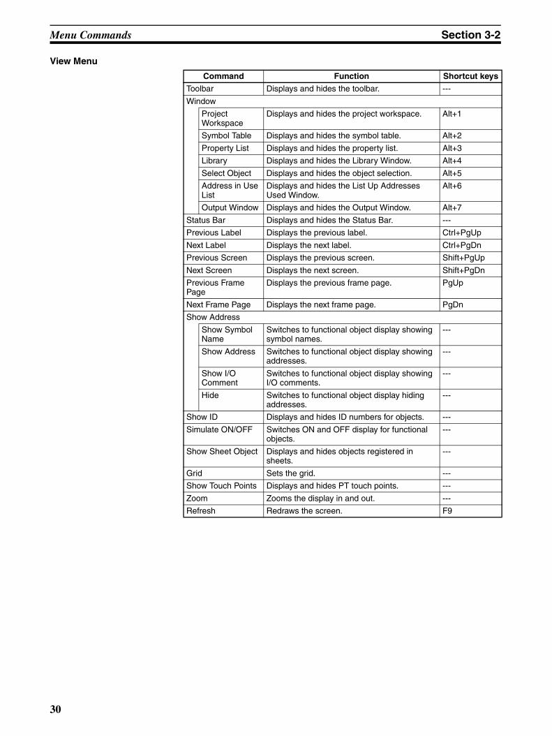
Command Function Shortcut keys
Toolbar Displays and hides the toolbar. ---
Window
Project Workspace
Displays and hides the project workspace. Alt+1
Symbol Table Displays and hides the symbol table. Alt+2
Property List Displays and hides the property list. Alt+3
Library Displays and hides the Library Window. Alt+4
Select Object Displays and hides the object selection. Alt+5
Address in Use List
Displays and hides the List Up Addresses Used Window.
Alt+6
Output Window Displays and hides the Output Window. Alt+7
Status Bar Displays and hides the Status Bar. ---
Previous Label Displays the previous label. Ctrl+PgUp
Next Label Displays the next label. Ctrl+PgDn
Previous Screen Displays the previous screen. Shift+PgUp
Next Screen Displays the next screen. Shift+PgDn
Previous Frame Page
Displays the previous frame page. PgUp
Next Frame Page Displays the next frame page. PgDn
Show Address
Show Symbol Name
Switches to functional object display showing symbol names.
---
Show Address Switches to functional object display showing addresses.
---
Show I/O Comment
Switches to functional object display showing I/O comments.
---
Hide Switches to functional object display hiding addresses.
---
Show ID Displays and hides ID numbers for objects. ---
Simulate ON/OFF Switches ON and OFF display for functional objects.
---
Show Sheet Object Displays and hides objects registered in sheets.
---
Grid Sets the grid. ---
Show Touch Points Displays and hides PT touch points. ---
Zoom Zooms the display in and out. ---
Refresh Redraws the screen. F9
30
Menu Commands Section 3-2
PT Menu
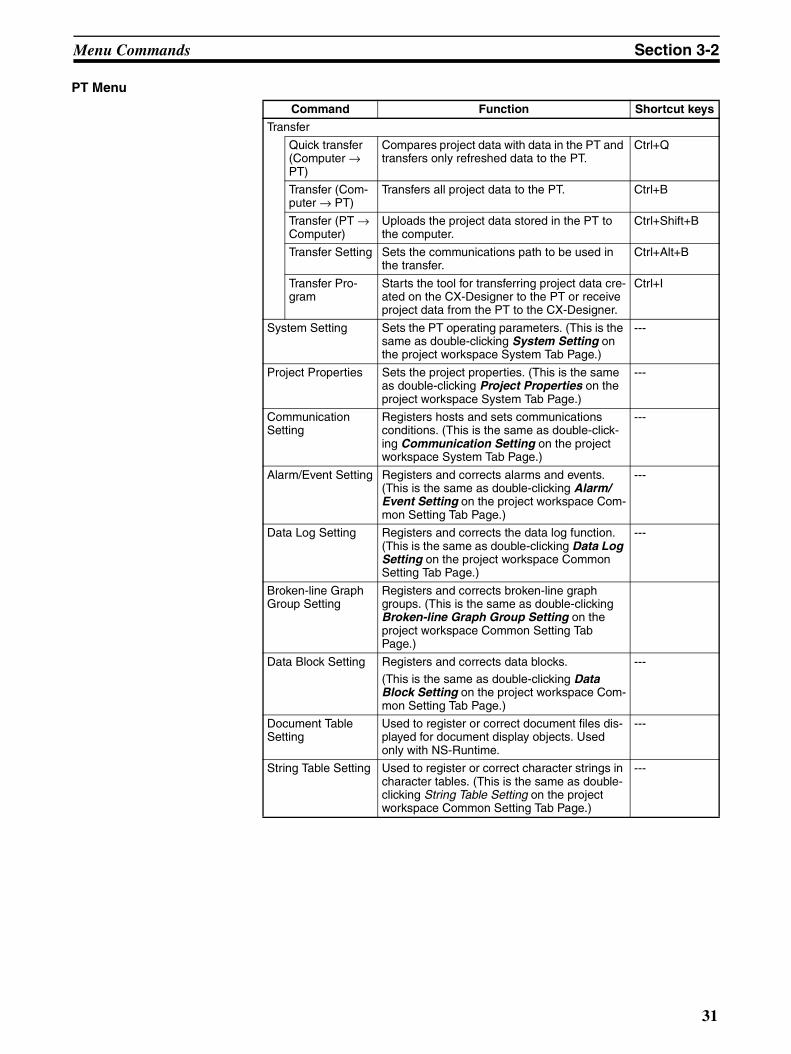
Command Function Shortcut keys
Transfer
Quick transfer (Computer → PT)
Compares project data with data in the PT and transfers only refreshed data to the PT.
Ctrl+Q
Transfer (Com-puter → PT)
Transfers all project data to the PT. Ctrl+B
Transfer (PT → Computer)
Uploads the project data stored in the PT to the computer.
Ctrl+Shift+B
Transfer Setting Sets the communications path to be used in the transfer.
Ctrl+Alt+B
Transfer Pro-gram
Starts the tool for transferring project data cre-ated on the CX-Designer to the PT or receive project data from the PT to the CX-Designer.
Ctrl+I
System Setting Sets the PT operating parameters. (This is the same as double-clicking System Setting on the project workspace System Tab Page.)
---
Project Properties Sets the project properties. (This is the same as double-clicking Project Properties on the project workspace System Tab Page.)
---
Communication Setting
Registers hosts and sets communications conditions. (This is the same as double-click-ing Communication Setting on the project workspace System Tab Page.)
---
Alarm/Event Setting Registers and corrects alarms and events. (This is the same as double-clicking Alarm/Event Setting on the project workspace Com-mon Setting Tab Page.)
---
Data Log Setting Registers and corrects the data log function. (This is the same as double-clicking Data Log Setting on the project workspace Common Setting Tab Page.)
---
Broken-line Graph Group Setting
Registers and corrects broken-line graph groups. (This is the same as double-clicking Broken-line Graph Group Setting on the project workspace Common Setting Tab Page.)
Data Block Setting Registers and corrects data blocks. (This is the same as double-clicking Data Block Setting on the project workspace Com-mon Setting Tab Page.)
---
Document Table Setting
Used to register or correct document files dis-played for document display objects. Used only with NS-Runtime.
---
String Table Setting Used to register or correct character strings in character tables. (This is the same as double-clicking String Table Setting on the project workspace Common Setting Tab Page.)
---
31
Menu Commands Section 3-2
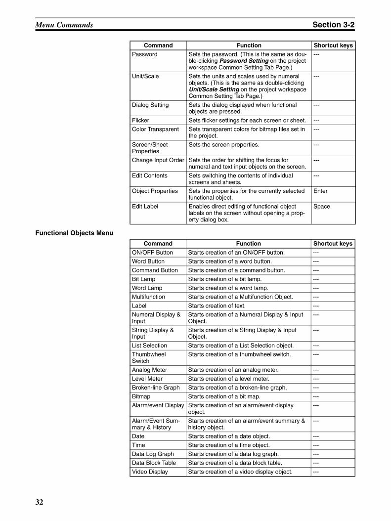
Functional Objects Menu
Password Sets the password. (This is the same as dou-ble-clicking Password Setting on the project workspace Common Setting Tab Page.)
---
Unit/Scale Sets the units and scales used by numeral objects. (This is the same as double-clicking Unit/Scale Setting on the project workspace Common Setting Tab Page.)
---
Dialog Setting Sets the dialog displayed when functional objects are pressed.
---
Flicker Sets flicker settings for each screen or sheet. ---
Color Transparent Sets transparent colors for bitmap files set in the project.
---
Screen/Sheet Properties
Sets the screen properties. ---
Change Input Order Sets the order for shifting the focus for numeral and text input objects on the screen.
---
Edit Contents Sets switching the contents of individual screens and sheets.
---
Object Properties Sets the properties for the currently selected functional object.
Enter
Edit Label Enables direct editing of functional object labels on the screen without opening a prop-erty dialog box.
Space
Command Function Shortcut keys
Command Function Shortcut keys
ON/OFF Button Starts creation of an ON/OFF button. ---
Word Button Starts creation of a word button. ---
Command Button Starts creation of a command button. ---
Bit Lamp Starts creation of a bit lamp. ---
Word Lamp Starts creation of a word lamp. ---
Multifunction Starts creation of a Multifunction Object. ---
Label Starts creation of text. ---
Numeral Display & Input
Starts creation of a Numeral Display & Input Object.
---
String Display & Input
Starts creation of a String Display & Input Object.
---
List Selection Starts creation of a List Selection object. ---
Thumbwheel Switch
Starts creation of a thumbwheel switch. ---
Analog Meter Starts creation of an analog meter. ---
Level Meter Starts creation of a level meter. ---
Broken-line Graph Starts creation of a broken-line graph. ---
Bitmap Starts creation of a bit map. ---
Alarm/event Display Starts creation of an alarm/event display object.
---
Alarm/Event Sum-mary & History
Starts creation of an alarm/event summary & history object.
---
Date Starts creation of a date object. ---
Time Starts creation of a time object. ---
Data Log Graph Starts creation of a data log graph. ---
Data Block Table Starts creation of a data block table. ---
Video Display Starts creation of a video display object. ---
32
Menu Commands Section 3-2
Fixed Objects Menu
Tools Menu
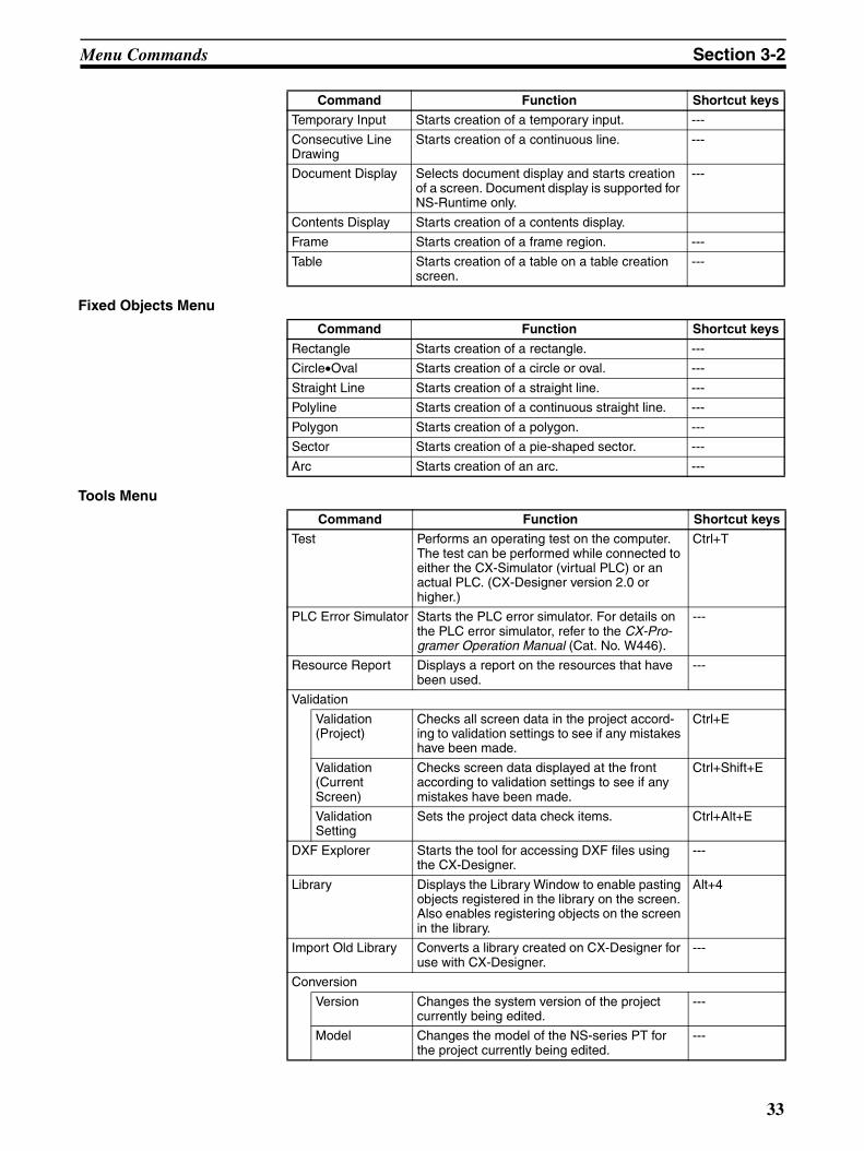
Temporary Input Starts creation of a temporary input. ---
Consecutive Line Drawing
Starts creation of a continuous line. ---
Document Display Selects document display and starts creation of a screen. Document display is supported for NS-Runtime only.
---
Contents Display Starts creation of a contents display.
Frame Starts creation of a frame region. ---
Table Starts creation of a table on a table creation screen.
---
Command Function Shortcut keys
Command Function Shortcut keys
Rectangle Starts creation of a rectangle. ---
Circle•Oval Starts creation of a circle or oval. ---
Straight Line Starts creation of a straight line. ---
Polyline Starts creation of a continuous straight line. ---
Polygon Starts creation of a polygon. ---
Sector Starts creation of a pie-shaped sector. ---
Arc Starts creation of an arc. ---
Command Function Shortcut keys
Test Performs an operating test on the computer. The test can be performed while connected to either the CX-Simulator (virtual PLC) or an actual PLC. (CX-Designer version 2.0 or higher.)
Ctrl+T
PLC Error Simulator Starts the PLC error simulator. For details on the PLC error simulator, refer to the CX-Pro-gramer Operation Manual (Cat. No. W446).
---
Resource Report Displays a report on the resources that have been used.
---
Validation
Validation (Project)
Checks all screen data in the project accord-ing to validation settings to see if any mistakes have been made.
Ctrl+E
Validation (Current Screen)
Checks screen data displayed at the front according to validation settings to see if any mistakes have been made.
Ctrl+Shift+E
Validation Setting
Sets the project data check items. Ctrl+Alt+E
DXF Explorer Starts the tool for accessing DXF files using the CX-Designer.
---
Library Displays the Library Window to enable pasting objects registered in the library on the screen. Also enables registering objects on the screen in the library.
Alt+4
Import Old Library Converts a library created on CX-Designer for use with CX-Designer.
---
Conversion
Version Changes the system version of the project currently being edited.
---
Model Changes the model of the NS-series PT for the project currently being edited.
---
33
User Interface Section 3-3
Window Menu
Help Menu
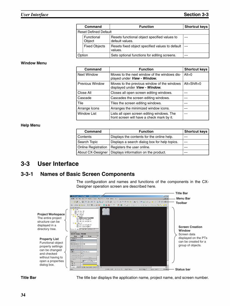
3-3 User Interface
3-3-1 Names of Basic Screen ComponentsThe configuration and names and functions of the components in the CX-Designer operation screen are described here.
Title Bar The title bar displays the application name, project name, and screen number.
Reset Defined Default
Functional Object
Resets functional object specified values to default values.
---
Fixed Objects Resets fixed object specified values to default values.
---
Option Sets optional functions for editing screens. ---
Command Function Shortcut keys
Command Function Shortcut keys
Next Window Moves to the next window of the windows dis-played under View - Window.
Alt+0
Previous Window Moves to the previous window of the windows displayed under View - Window.
Alt+Shift+0
Close All Closes all open screen editing windows. ---
Cascade Cascades the screen editing windows. ---
Tile Tiles the screen editing windows. ---
Arrange Icons Arranges the minimized window icons. ---
Window List Lists all open screen editing windows. The front screen will have a check mark by it.
---
Command Function Shortcut keys
Contents Displays the contents for the online help. ---
Search Topic Displays a search dialog box for help topics. ---
Online Registration Registers the user online. ---
About CX-Designer Displays information on the product. ---
Title Bar
Menu BarToolbar
Status bar
Property ListFunctional object property settings can be changed and checked without having to open a properties dialog box.
Project WorkspaceThe entire project structure can be displayed in a directory tree.
Screen Creation WindowScreen data displayed on the PTs can be created for a group of objects.
34
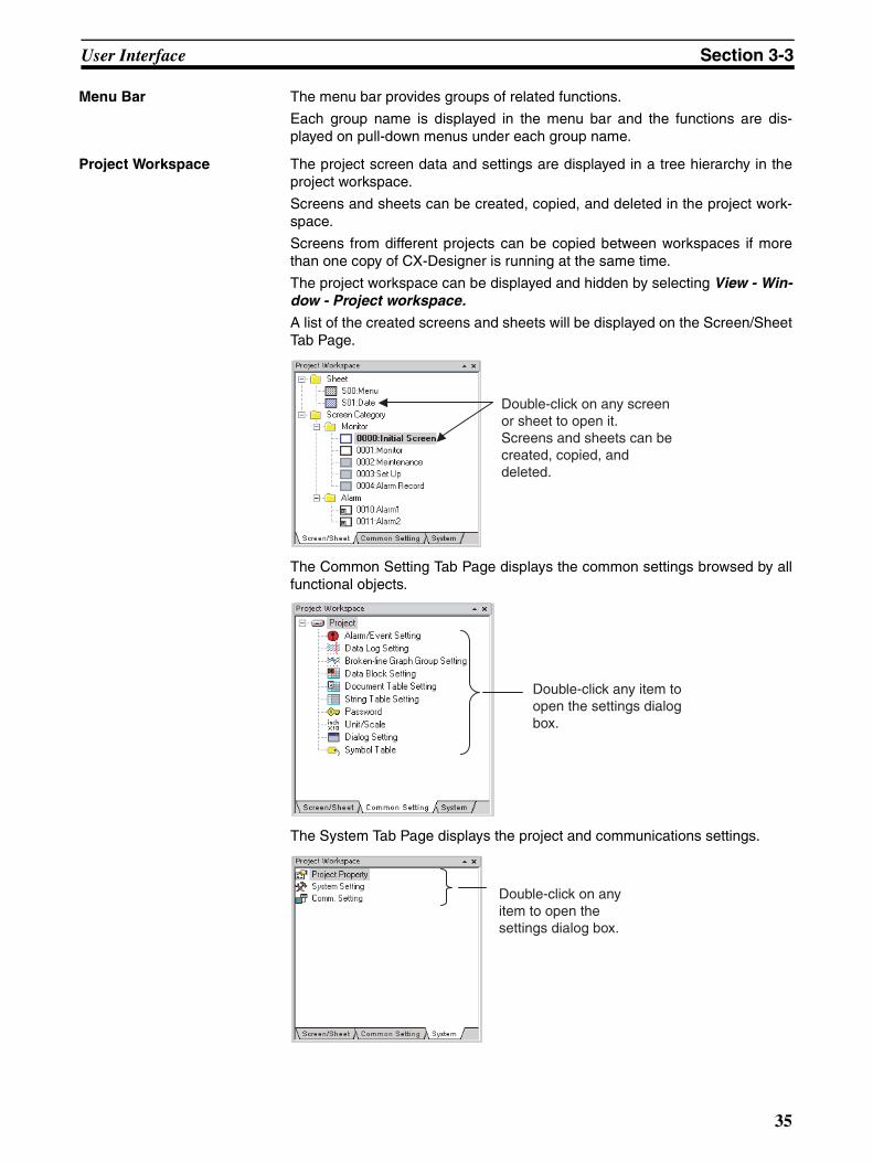
User Interface Section 3-3
Menu Bar The menu bar provides groups of related functions.
Each group name is displayed in the menu bar and the functions are dis-played on pull-down menus under each group name.
Project Workspace The project screen data and settings are displayed in a tree hierarchy in theproject workspace.
Screens and sheets can be created, copied, and deleted in the project work-space.
Screens from different projects can be copied between workspaces if morethan one copy of CX-Designer is running at the same time.
The project workspace can be displayed and hidden by selecting View - Win-dow - Project workspace.
A list of the created screens and sheets will be displayed on the Screen/SheetTab Page.
The Common Setting Tab Page displays the common settings browsed by allfunctional objects.
The System Tab Page displays the project and communications settings.
Double-click on any screen or sheet to open it. Screens and sheets can be created, copied, and deleted.
Double-click any item to open the settings dialog box.
Double-click on any item to open the settings dialog box.
35
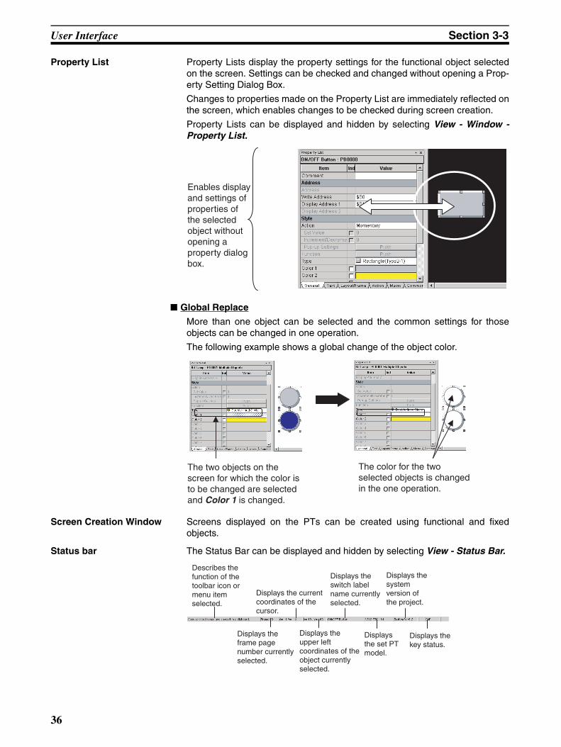
User Interface Section 3-3
Property List Property Lists display the property settings for the functional object selectedon the screen. Settings can be checked and changed without opening a Prop-erty Setting Dialog Box.
Changes to properties made on the Property List are immediately reflected onthe screen, which enables changes to be checked during screen creation.
Property Lists can be displayed and hidden by selecting View - Window -Property List.
■ Global Replace
More than one object can be selected and the common settings for thoseobjects can be changed in one operation.
The following example shows a global change of the object color.
Screen Creation Window Screens displayed on the PTs can be created using functional and fixedobjects.
Status bar The Status Bar can be displayed and hidden by selecting View - Status Bar.
Enables display and settings of properties of the selected object without opening a property dialog box.
The two objects on the screen for which the color is to be changed are selected and Color 1 is changed.
The color for the two selected objects is changed in the one operation.
Describes the function of the toolbar icon or menu item selected.
Displays the frame page number currently selected.
Displays the current coordinates of the cursor.
Displays the upper left coordinates of the object currently selected.
Displays the switch label name currently selected.
Displays the set PT model.
Displays the system version of the project.
Displays the key status.
36
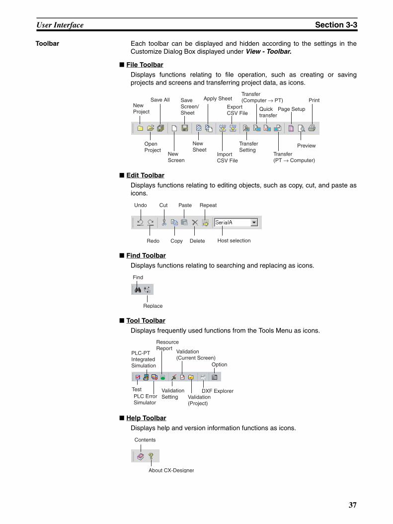
User Interface Section 3-3
Toolbar Each toolbar can be displayed and hidden according to the settings in theCustomize Dialog Box displayed under View - Toolbar.
■ File Toolbar
Displays functions relating to file operation, such as creating or savingprojects and screens and transferring project data, as icons.
■ Edit Toolbar
Displays functions relating to editing objects, such as copy, cut, and paste asicons.
■ Find Toolbar
Displays functions relating to searching and replacing as icons.
■ Tool Toolbar
Displays frequently used functions from the Tools Menu as icons.
■ Help Toolbar
Displays help and version information functions as icons.
New Project
Open Project
New Screen
New Sheet
Transfer Setting
Import CSV File
Transfer (PT → Computer)
Save All Save Screen/ Sheet
Apply Sheet
Export CSV File
Transfer (Computer → PT)
Preview
Page Setup
Quicktransfer
Undo Cut Paste Repeat
Redo Copy Delete Host selection
Find
Replace
Test
Resource Report
Validation Setting
PLC-PT Integrated Simulation
Validation (Project)
Validation (Current Screen)
Option
PLC Error Simulator
DXF Explorer
Contents
About CX-Designer
37
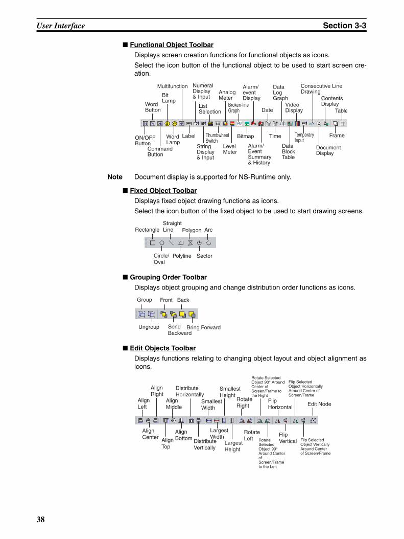
User Interface Section 3-3
■ Functional Object Toolbar
Displays screen creation functions for functional objects as icons.
Select the icon button of the functional object to be used to start screen cre-ation.
Note Document display is supported for NS-Runtime only.
■ Fixed Object Toolbar
Displays fixed object drawing functions as icons.
Select the icon button of the fixed object to be used to start drawing screens.
■ Grouping Order Toolbar
Displays object grouping and change distribution order functions as icons.
■ Edit Objects Toolbar
Displays functions relating to changing object layout and object alignment asicons.
ON/OFF Button
Word Lamp
List Selection
Broken-line Graph Date
Video Display
Command Button
Numeral Display & Input
Analog Meter
Alarm/ event Display
Data Log Graph
Frame
Table
Bit Lamp
String Display & Input
Level Meter
Alarm/ Event Summary & History
Data Block Table
Word Button
Label Thumbwheel Switch
Bitmap Time Temporary Input
DocumentDisplay
Consecutive LineDrawing
Contents Display
Multifunction
Rectangle
Circle/ Oval
Polyline Sector
Straight Line Polygon Arc
Group Front Back
Send Backward
Bring ForwardUngroup
Align Left
Align Middle
Align Right
Distribute Horizontally
Smallest Width
Smallest Height
Rotate Right
Flip Horizontal Edit Node
Align Top
Align Center
Align Bottom Distribute
VerticallyLargest Height
Largest Width
Rotate Left
Flip Vertical
Rotate Selected Object 90° Around Center of Screen/Frame to the Right
Rotate Selected Object 90° Around Center of Screen/Frame to the Left
Flip Selected Object Vertically Around Center of Screen/Frame
Flip Selected Object Horizontally Around Center of Screen/Frame
38
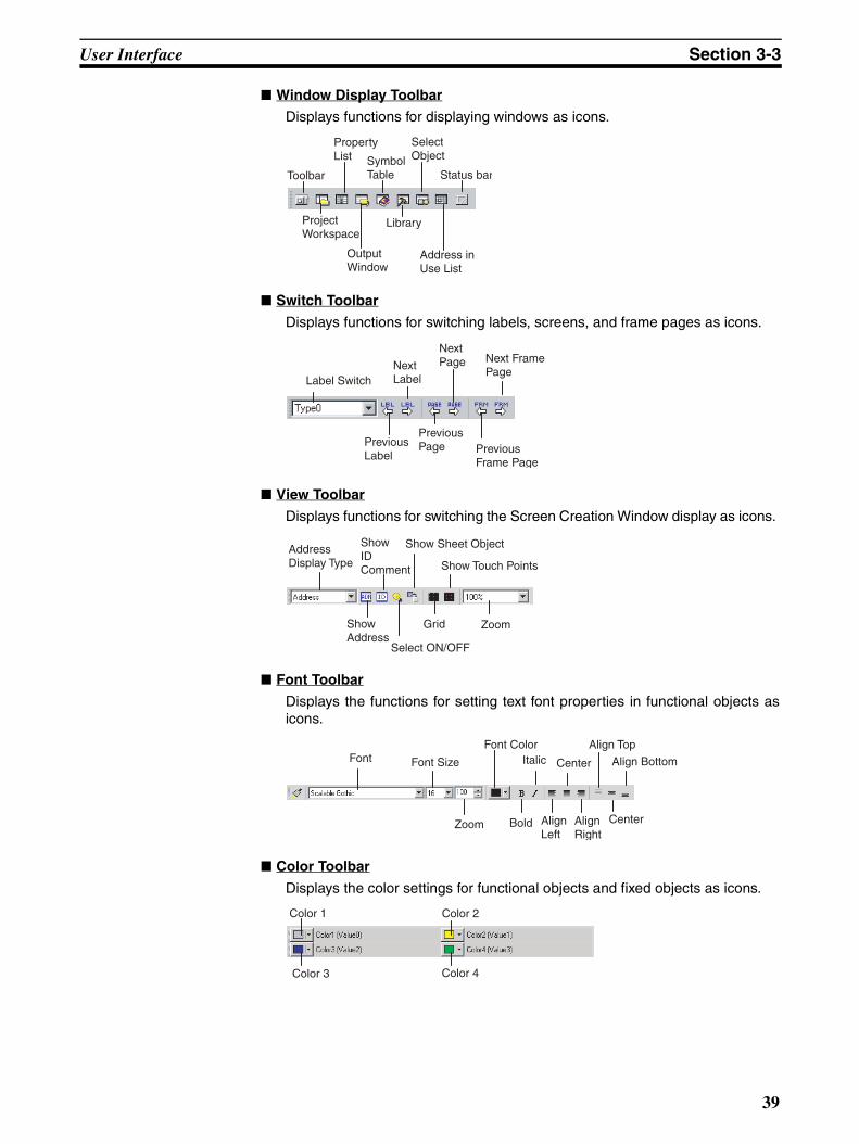
User Interface Section 3-3
■ Window Display Toolbar
Displays functions for displaying windows as icons.
■ Switch Toolbar
Displays functions for switching labels, screens, and frame pages as icons.
■ View Toolbar
Displays functions for switching the Screen Creation Window display as icons.
■ Font Toolbar
Displays the functions for setting text font properties in functional objects asicons.
■ Color Toolbar
Displays the color settings for functional objects and fixed objects as icons.
Toolbar
Property List Symbol
Table
Select Object
Status bar
Project Workspace
Output Window
Library
Address in Use List
Label Switch
Previous Label
Previous Page
Next Label
Previous Frame Page
Next Page Next Frame
Page
Address Display Type
Show ID Comment
Show Sheet Object
Show Touch Points
Show Address
Select ON/OFF
Grid Zoom
Font Font Size Italic Center Align Bottom
Font Color Align Top
Bold Align Left
Align Right
CenterZoom
Color 1 Color 2
Color 4Color 3
39
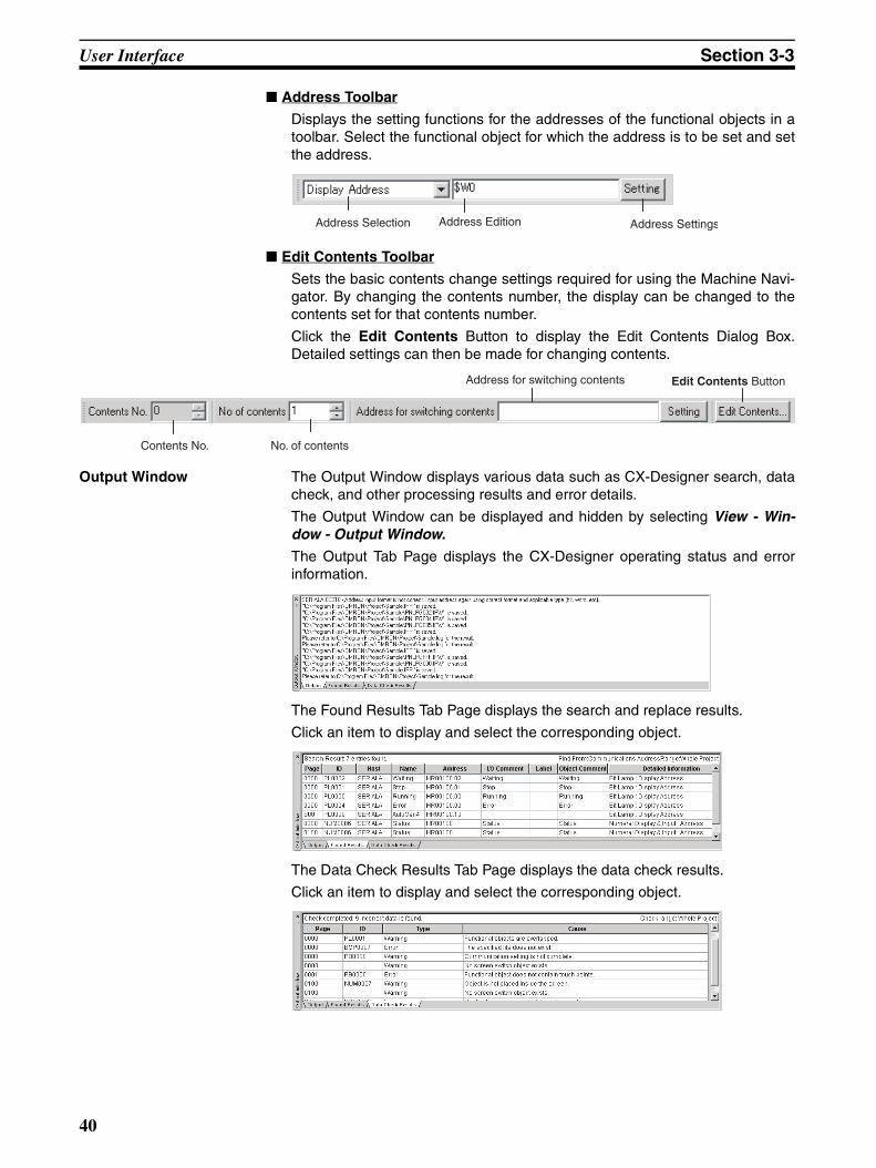
User Interface Section 3-3
■ Address Toolbar
Displays the setting functions for the addresses of the functional objects in atoolbar. Select the functional object for which the address is to be set and setthe address.
■ Edit Contents Toolbar
Sets the basic contents change settings required for using the Machine Navi-gator. By changing the contents number, the display can be changed to thecontents set for that contents number.
Click the Edit Contents Button to display the Edit Contents Dialog Box.Detailed settings can then be made for changing contents.
Output Window The Output Window displays various data such as CX-Designer search, datacheck, and other processing results and error details.
The Output Window can be displayed and hidden by selecting View - Win-dow - Output Window.
The Output Tab Page displays the CX-Designer operating status and errorinformation.
The Found Results Tab Page displays the search and replace results.
Click an item to display and select the corresponding object.
The Data Check Results Tab Page displays the data check results.
Click an item to display and select the corresponding object.
Address Selection Address Edition Address Settings
Contents No.
Address for switching contents Edit Contents Button
No. of contents
40
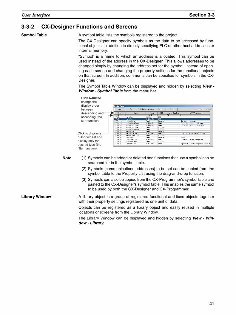
User Interface Section 3-3
3-3-2 CX-Designer Functions and ScreensSymbol Table A symbol table lists the symbols registered to the project.
The CX-Designer can specify symbols as the data to be accessed by func-tional objects, in addition to directly specifying PLC or other host addresses orinternal memory.
“Symbol” is a name to which an address is allocated. This symbol can beused instead of the address in the CX-Designer. This allows addresses to bechanged simply by changing the address set for the symbol, instead of open-ing each screen and changing the property settings for the functional objectson that screen. In addition, comments can be specified for symbols in the CX-Designer.
The Symbol Table Window can be displayed and hidden by selecting View -Window - Symbol Table from the menu bar.
Note (1) Symbols can be added or deleted and functions that use a symbol can besearched for in the symbol table.
(2) Symbols (communications addresses) to be set can be copied from thesymbol table to the Property List using the drag-and-drop function.
(3) Symbols can also be copied from the CX-Programmer's symbol table andpasted to the CX-Designer's symbol table. This enables the same symbolto be used by both the CX-Designer and CX-Programmer.
Library Window A library object is a group of registered functional and fixed objects togetherwith their property settings registered as one unit of data.
Objects can be registered as a library object and easily reused in multiplelocations or screens from the Library Window.
The Library Window can be displayed and hidden by selecting View - Win-dow - Library.
Click Name to change the display order between descending and ascending (the sort function).
Click to display a pull-down list and display only the desired type (the filter function).
41
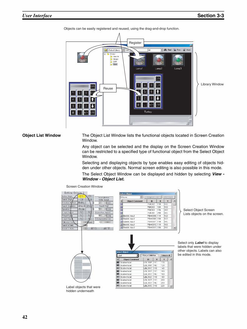
User Interface Section 3-3
Object List Window The Object List Window lists the functional objects located in Screen CreationWindow.
Any object can be selected and the display on the Screen Creation Windowcan be restricted to a specified type of functional object from the Select ObjectWindow.
Selecting and displaying objects by type enables easy editing of objects hid-den under other objects. Normal screen editing is also possible in this mode.
The Select Object Window can be displayed and hidden by selecting View -Window - Object List.
Objects can be easily registered and reused, using the drag-and-drop function.
Register
ReuseLibrary Window
Screen Creation Window
Select Object ScreenLists objects on the screen.
Label objects that were hidden underneath
Select only Label to display labels that were hidden under other objects. Labels can also be edited in this mode.
42
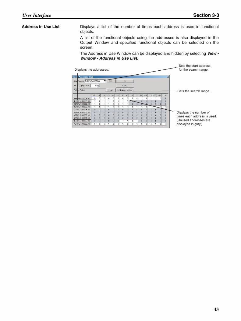
User Interface Section 3-3
Address in Use List Displays a list of the number of times each address is used in functionalobjects.
A list of the functional objects using the addresses is also displayed in theOutput Window and specified functional objects can be selected on thescreen.
The Address in Use Window can be displayed and hidden by selecting View -Window - Address in Use List.
Displays the addresses.
Sets the search range.
Displays the number of times each address is used. (Unused addresses are displayed in gray.)
Sets the start address for the search range.
43

User Interface Section 3-3
44
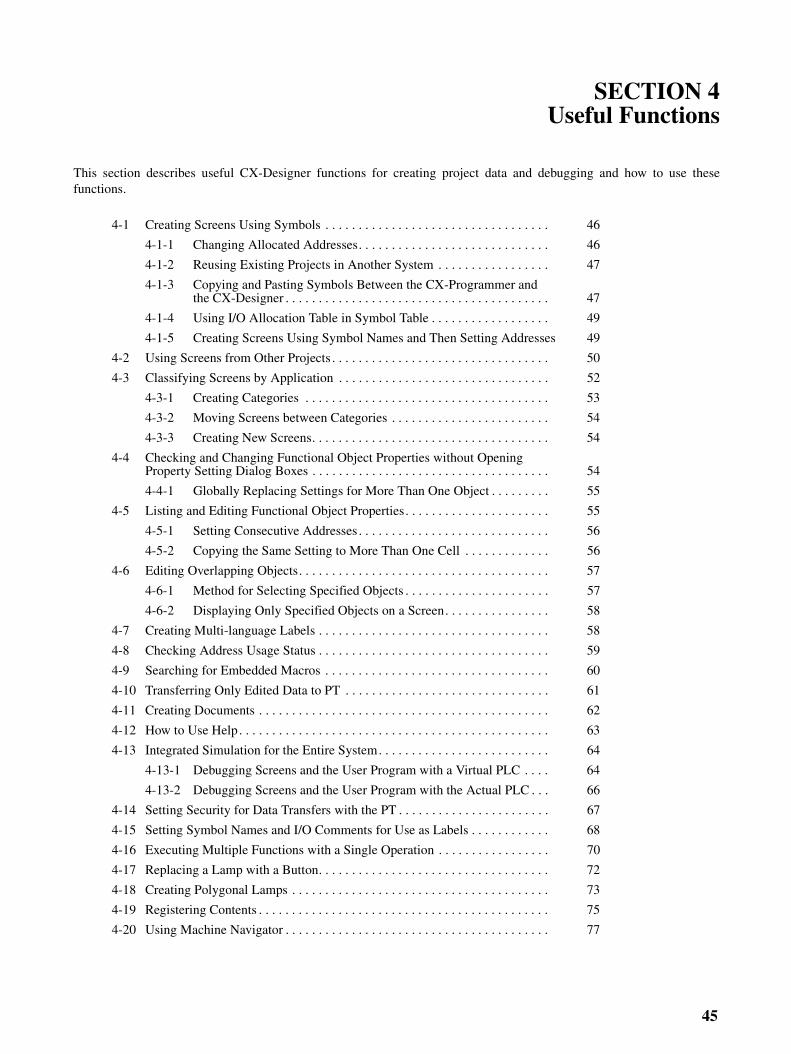
SECTION 4Useful Functions
This section describes useful CX-Designer functions for creating project data and debugging and how to use thesefunctions.
4-1 Creating Screens Using Symbols . . . . . . . . . . . . . . . . . . . . . . . . . . . . . . . . . . 46
4-1-1 Changing Allocated Addresses. . . . . . . . . . . . . . . . . . . . . . . . . . . . . 46
4-1-2 Reusing Existing Projects in Another System . . . . . . . . . . . . . . . . . 47
4-1-3 Copying and Pasting Symbols Between the CX-Programmer and the CX-Designer . . . . . . . . . . . . . . . . . . . . . . . . . . . . . . . . . . . . . . . . 47
4-1-4 Using I/O Allocation Table in Symbol Table . . . . . . . . . . . . . . . . . . 49
4-1-5 Creating Screens Using Symbol Names and Then Setting Addresses 49
4-2 Using Screens from Other Projects . . . . . . . . . . . . . . . . . . . . . . . . . . . . . . . . . 50
4-3 Classifying Screens by Application . . . . . . . . . . . . . . . . . . . . . . . . . . . . . . . . 52
4-3-1 Creating Categories . . . . . . . . . . . . . . . . . . . . . . . . . . . . . . . . . . . . . 53
4-3-2 Moving Screens between Categories . . . . . . . . . . . . . . . . . . . . . . . . 54
4-3-3 Creating New Screens. . . . . . . . . . . . . . . . . . . . . . . . . . . . . . . . . . . . 54
4-4 Checking and Changing Functional Object Properties without Opening Property Setting Dialog Boxes . . . . . . . . . . . . . . . . . . . . . . . . . . . . . . . . . . . . 54
4-4-1 Globally Replacing Settings for More Than One Object . . . . . . . . . 55
4-5 Listing and Editing Functional Object Properties. . . . . . . . . . . . . . . . . . . . . . 55
4-5-1 Setting Consecutive Addresses . . . . . . . . . . . . . . . . . . . . . . . . . . . . . 56
4-5-2 Copying the Same Setting to More Than One Cell . . . . . . . . . . . . . 56
4-6 Editing Overlapping Objects. . . . . . . . . . . . . . . . . . . . . . . . . . . . . . . . . . . . . . 57
4-6-1 Method for Selecting Specified Objects . . . . . . . . . . . . . . . . . . . . . . 57
4-6-2 Displaying Only Specified Objects on a Screen. . . . . . . . . . . . . . . . 58
4-7 Creating Multi-language Labels . . . . . . . . . . . . . . . . . . . . . . . . . . . . . . . . . . . 58
4-8 Checking Address Usage Status . . . . . . . . . . . . . . . . . . . . . . . . . . . . . . . . . . . 59
4-9 Searching for Embedded Macros . . . . . . . . . . . . . . . . . . . . . . . . . . . . . . . . . . 60
4-10 Transferring Only Edited Data to PT . . . . . . . . . . . . . . . . . . . . . . . . . . . . . . . 61
4-11 Creating Documents . . . . . . . . . . . . . . . . . . . . . . . . . . . . . . . . . . . . . . . . . . . . 62
4-12 How to Use Help. . . . . . . . . . . . . . . . . . . . . . . . . . . . . . . . . . . . . . . . . . . . . . . 63
4-13 Integrated Simulation for the Entire System. . . . . . . . . . . . . . . . . . . . . . . . . . 64
4-13-1 Debugging Screens and the User Program with a Virtual PLC . . . . 64
4-13-2 Debugging Screens and the User Program with the Actual PLC . . . 66
4-14 Setting Security for Data Transfers with the PT . . . . . . . . . . . . . . . . . . . . . . . 67
4-15 Setting Symbol Names and I/O Comments for Use as Labels . . . . . . . . . . . . 68
4-16 Executing Multiple Functions with a Single Operation . . . . . . . . . . . . . . . . . 70
4-17 Replacing a Lamp with a Button. . . . . . . . . . . . . . . . . . . . . . . . . . . . . . . . . . . 72
4-18 Creating Polygonal Lamps . . . . . . . . . . . . . . . . . . . . . . . . . . . . . . . . . . . . . . . 73
4-19 Registering Contents . . . . . . . . . . . . . . . . . . . . . . . . . . . . . . . . . . . . . . . . . . . . 75
4-20 Using Machine Navigator . . . . . . . . . . . . . . . . . . . . . . . . . . . . . . . . . . . . . . . . 77
45
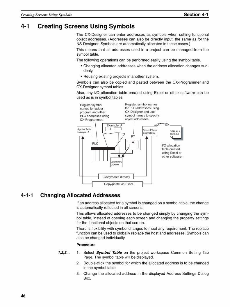
Creating Screens Using Symbols Section 4-1
4-1 Creating Screens Using SymbolsThe CX-Designer can enter addresses as symbols when setting functionalobject addresses. (Addresses can also be directly input, the same as for theNS-Designer. Symbols are automatically allocated in these cases.)
This means that all addresses used in a project can be managed from thesymbol table.
The following operations can be performed easily using the symbol table.
• Changing allocated addresses when the address allocation changes sud-denly.
• Reusing existing projects in another system.
Symbols can also be copied and pasted between the CX-Programmer andCX-Designer symbol tables.
Also, any I/O allocation table created using Excel or other software can beused as is in symbol tables.
4-1-1 Changing Allocated AddressesIf an address allocated for a symbol is changed on a symbol table, the changeis automatically reflected in all screens.
This allows allocated addresses to be changed simply by changing the sym-bol table, instead of opening each screen and changing the property settingsfor the functional objects on that screen.
There is flexibility with symbol changes to meet any requirement. The replacefunction can be used to globally replace the host and addresses. Symbols canalso be changed individually.
Procedure
1,2,3... 1. Select Symbol Table on the project workspace Common Setting TabPage. The symbol table will be displayed.
2. Double-click the symbol for which the allocated address is to be changedin the symbol table.
3. Change the allocated address in the displayed Address Settings DialogBox.
PLC A
Symbol TableExample: A
I/O memory CIO0.00
Copy/paste directly.
Copy/paste via Excel.
PT
Symbol TableExample: A
SERIAL A: CIO0.00
Example: A
Register symbol names for ladder program and other PLC addresses using CX-Programmer.
Register symbol names for PLC addresses using CX-Designer and use symbol names to specify object addresses.
I/O allocation table created using Excel or other software.
46
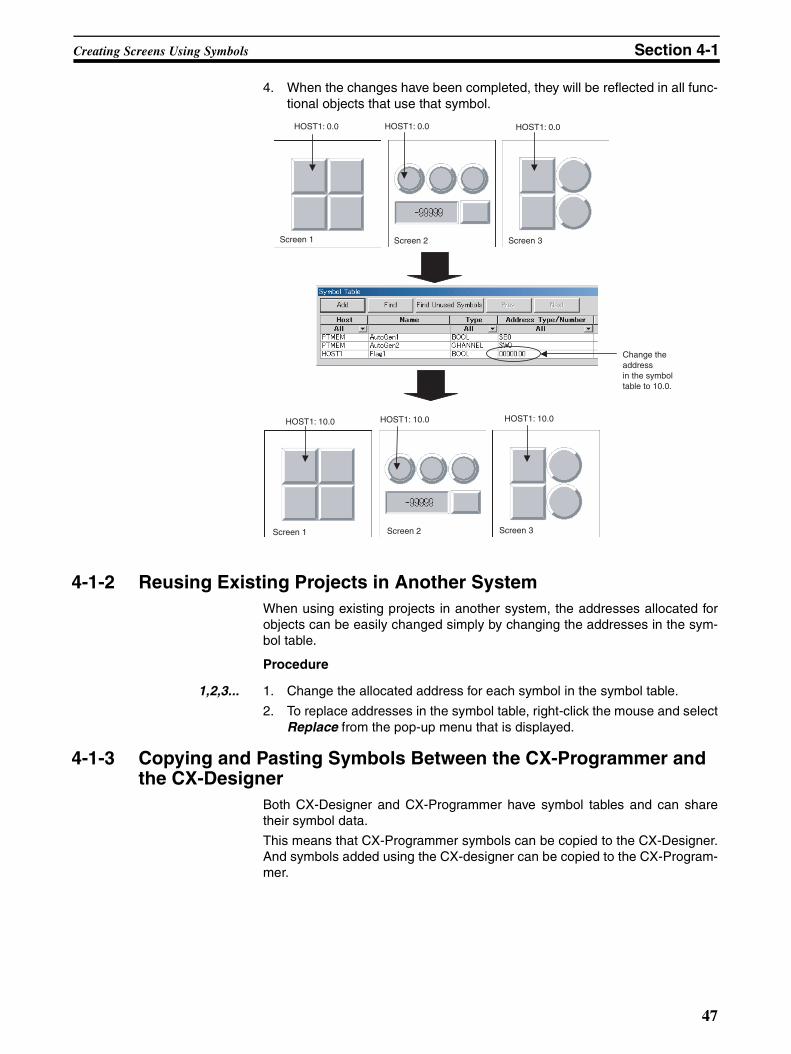
Creating Screens Using Symbols Section 4-1
4. When the changes have been completed, they will be reflected in all func-tional objects that use that symbol.
4-1-2 Reusing Existing Projects in Another SystemWhen using existing projects in another system, the addresses allocated forobjects can be easily changed simply by changing the addresses in the sym-bol table.
Procedure
1,2,3... 1. Change the allocated address for each symbol in the symbol table.
2. To replace addresses in the symbol table, right-click the mouse and selectReplace from the pop-up menu that is displayed.
4-1-3 Copying and Pasting Symbols Between the CX-Programmer and the CX-Designer
Both CX-Designer and CX-Programmer have symbol tables and can sharetheir symbol data.
This means that CX-Programmer symbols can be copied to the CX-Designer.And symbols added using the CX-designer can be copied to the CX-Program-mer.
HOST1: 0.0 HOST1: 0.0 HOST1: 0.0
HOST1: 10.0 HOST1: 10.0 HOST1: 10.0
Screen 1 Screen 2 Screen 3
Screen 3Screen 2Screen 1
Change the address in the symbol table to 10.0.
47
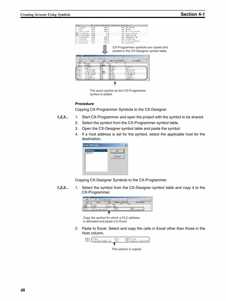
Creating Screens Using Symbols Section 4-1
Procedure
Copying CX-Programmer Symbols to the CX-Designer
1,2,3... 1. Start CX-Programmer and open the project with the symbol to be shared.
2. Select the symbol from the CX-Programmer symbol table.
3. Open the CX-Designer symbol table and paste the symbol.
4. If a host address is set for the symbol, select the applicable host for thedestination.
Copying CX-Designer Symbols to the CX-Programmer
1,2,3... 1. Select the symbol from the CX-Designer symbol table and copy it to theCX-Programmer.
2. Paste to Excel. Select and copy the cells in Excel other than those in theHost column.
The same symbol as the CX-Programmer symbol is added.
CX-Programmer symbols are copied and pasted to the CX-Designer symbol table.
Copy the symbol for which a PLC address is allocated and paste it to Excel.
This section is copied.
48
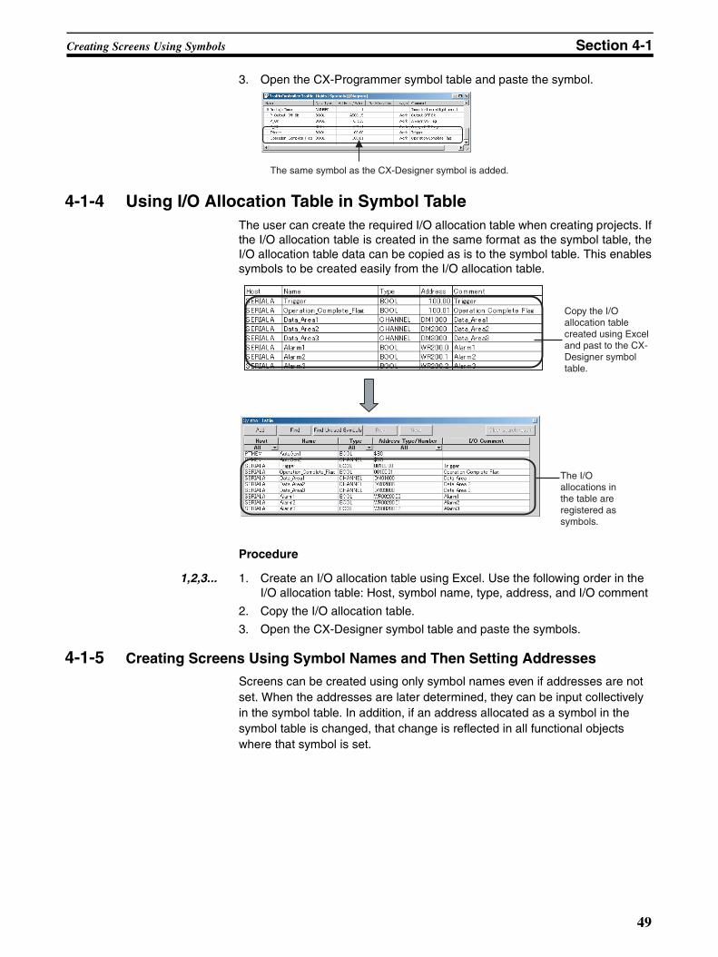
Creating Screens Using Symbols Section 4-1
3. Open the CX-Programmer symbol table and paste the symbol.
4-1-4 Using I/O Allocation Table in Symbol TableThe user can create the required I/O allocation table when creating projects. Ifthe I/O allocation table is created in the same format as the symbol table, theI/O allocation table data can be copied as is to the symbol table. This enablessymbols to be created easily from the I/O allocation table.
Procedure
1,2,3... 1. Create an I/O allocation table using Excel. Use the following order in the I/O allocation table: Host, symbol name, type, address, and I/O comment
2. Copy the I/O allocation table.
3. Open the CX-Designer symbol table and paste the symbols.
4-1-5 Creating Screens Using Symbol Names and Then Setting Addresses
Screens can be created using only symbol names even if addresses are not set. When the addresses are later determined, they can be input collectively in the symbol table. In addition, if an address allocated as a symbol in the symbol table is changed, that change is reflected in all functional objects where that symbol is set.
The same symbol as the CX-Designer symbol is added.
Copy the I/O allocation table created using Excel and past to the CX-Designer symbol table.
The I/O allocations in the table are registered as symbols.
49
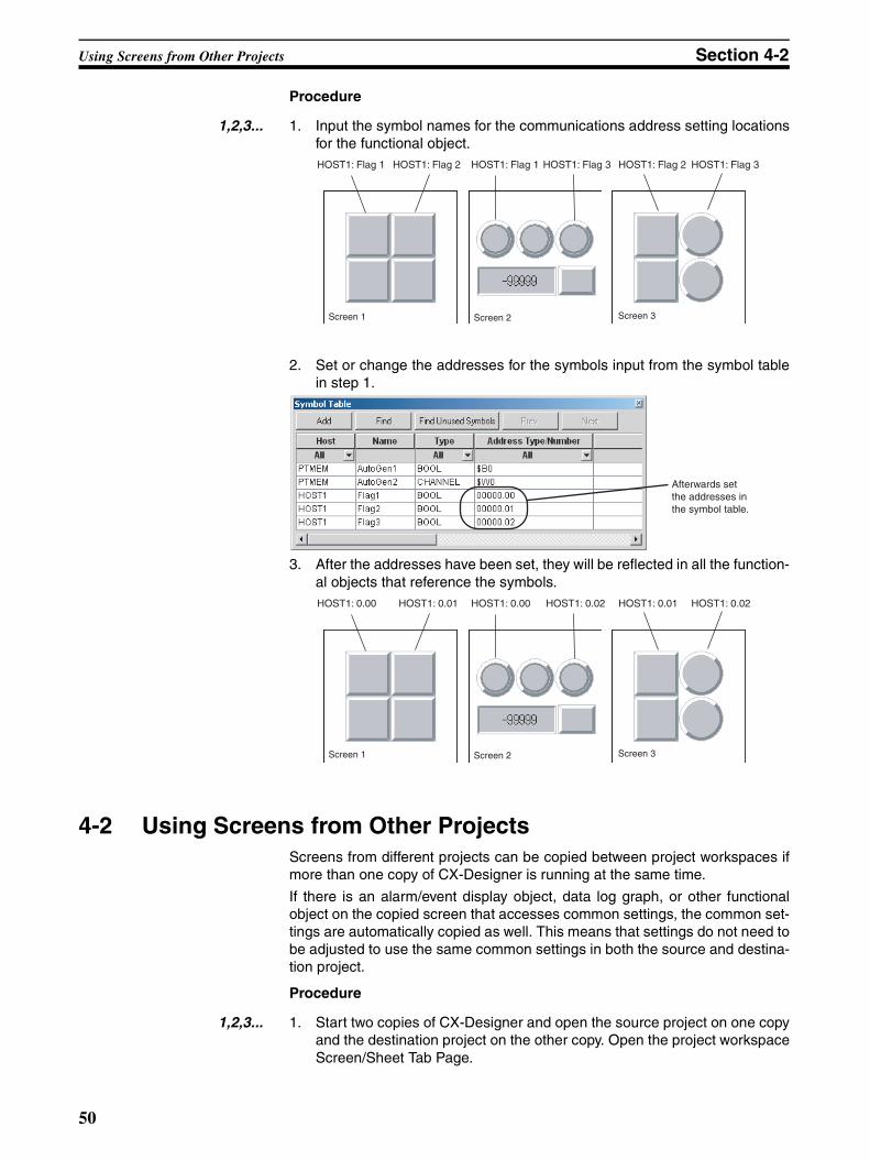
Using Screens from Other Projects Section 4-2
Procedure
1,2,3... 1. Input the symbol names for the communications address setting locationsfor the functional object.
2. Set or change the addresses for the symbols input from the symbol tablein step 1.
3. After the addresses have been set, they will be reflected in all the function-al objects that reference the symbols.
4-2 Using Screens from Other ProjectsScreens from different projects can be copied between project workspaces ifmore than one copy of CX-Designer is running at the same time.
If there is an alarm/event display object, data log graph, or other functionalobject on the copied screen that accesses common settings, the common set-tings are automatically copied as well. This means that settings do not need tobe adjusted to use the same common settings in both the source and destina-tion project.
Procedure
1,2,3... 1. Start two copies of CX-Designer and open the source project on one copyand the destination project on the other copy. Open the project workspaceScreen/Sheet Tab Page.
HOST1: Flag 1 HOST1: Flag 2 HOST1: Flag 1 HOST1: Flag 3 HOST1: Flag 2 HOST1: Flag 3
Screen 1 Screen 2 Screen 3
Afterwards set the addresses in the symbol table.
HOST1: 0.00 HOST1: 0.01 HOST1: 0.00 HOST1: 0.02 HOST1: 0.01 HOST1: 0.02
Screen 1 Screen 2 Screen 3
50
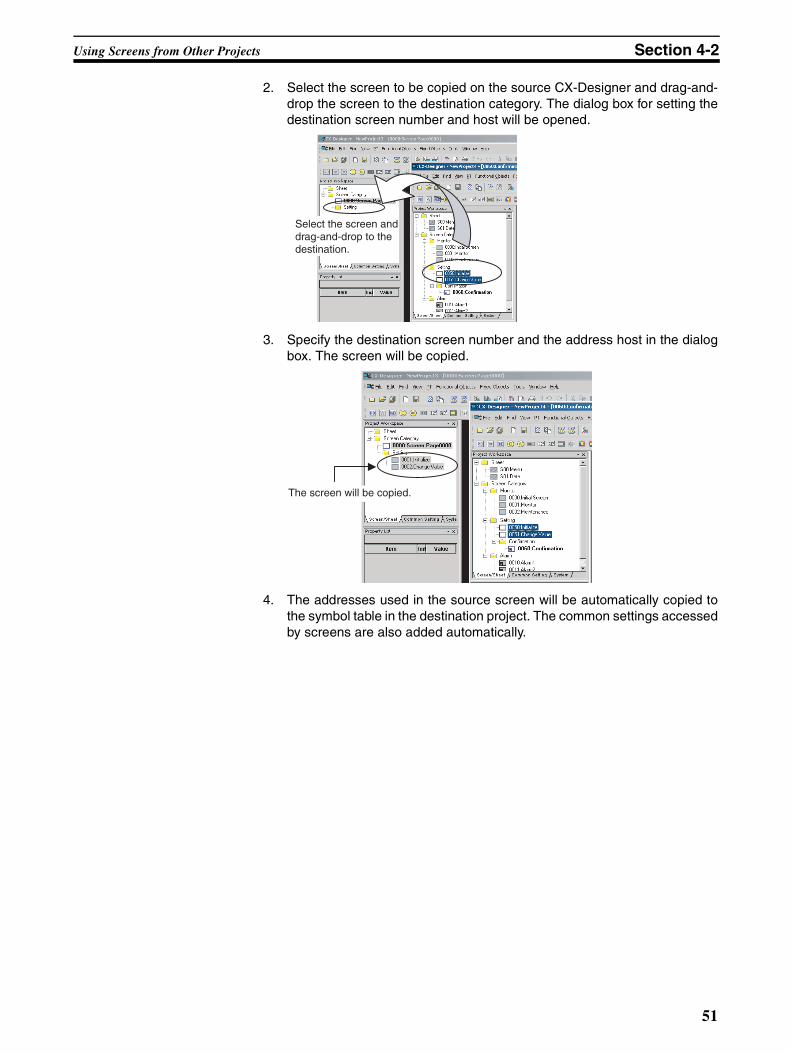
Using Screens from Other Projects Section 4-2
2. Select the screen to be copied on the source CX-Designer and drag-and-drop the screen to the destination category. The dialog box for setting thedestination screen number and host will be opened.
3. Specify the destination screen number and the address host in the dialogbox. The screen will be copied.
4. The addresses used in the source screen will be automatically copied tothe symbol table in the destination project. The common settings accessedby screens are also added automatically.
Select the screen and drag-and-drop to the destination.
The screen will be copied.
51
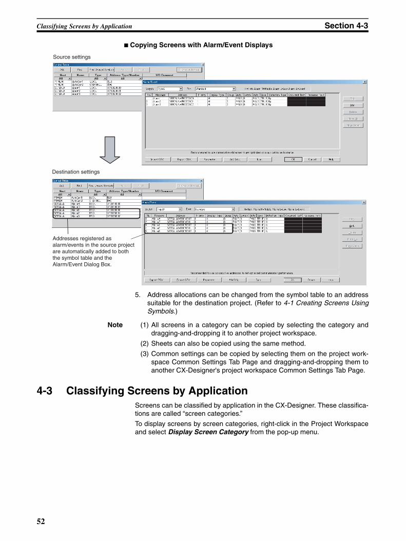
Classifying Screens by Application Section 4-3
■ Copying Screens with Alarm/Event Displays
5. Address allocations can be changed from the symbol table to an addresssuitable for the destination project. (Refer to 4-1 Creating Screens UsingSymbols.)
Note (1) All screens in a category can be copied by selecting the category anddragging-and-dropping it to another project workspace.
(2) Sheets can also be copied using the same method.
(3) Common settings can be copied by selecting them on the project work-space Common Settings Tab Page and dragging-and-dropping them toanother CX-Designer's project workspace Common Settings Tab Page.
4-3 Classifying Screens by ApplicationScreens can be classified by application in the CX-Designer. These classifica-tions are called “screen categories.”
To display screens by screen categories, right-click in the Project Workspaceand select Display Screen Category from the pop-up menu.
Source settings
Destination settings
Addresses registered as alarm/events in the source project are automatically added to both the symbol table and the Alarm/Event Dialog Box.
52
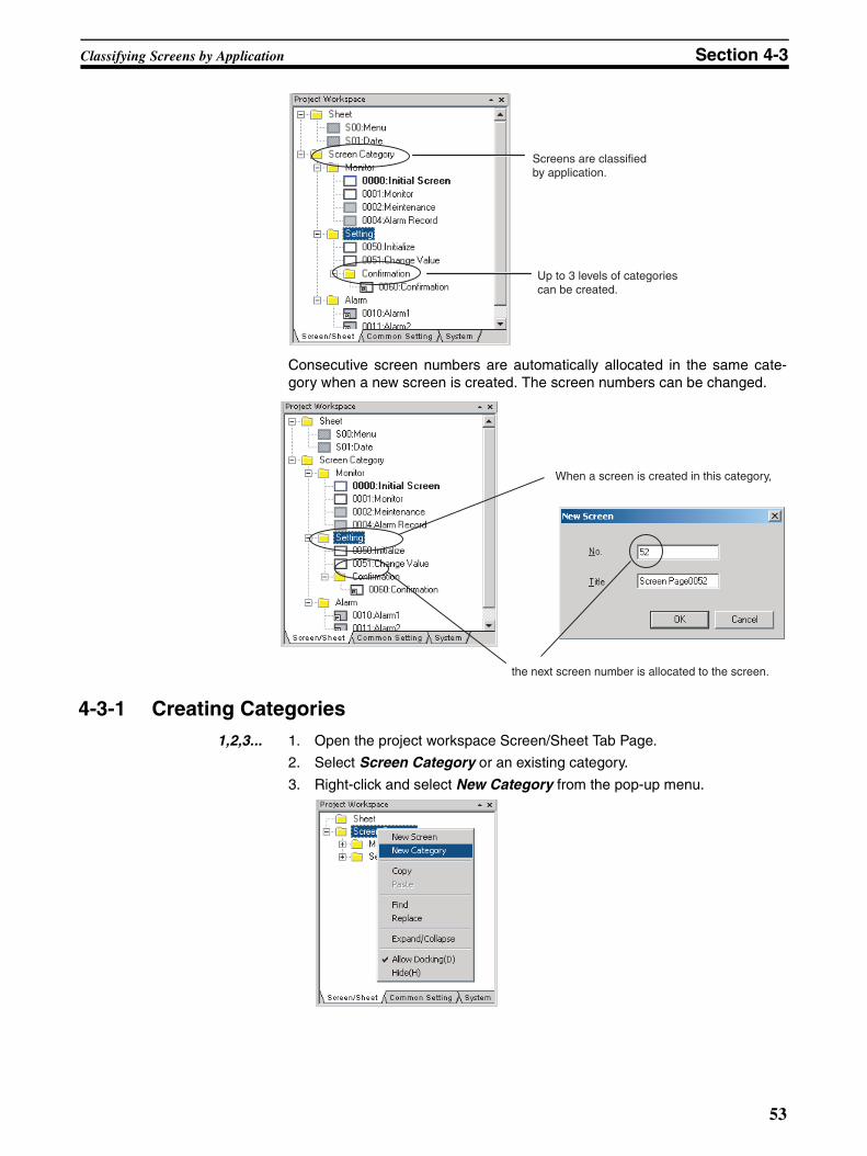
Classifying Screens by Application Section 4-3
Consecutive screen numbers are automatically allocated in the same cate-gory when a new screen is created. The screen numbers can be changed.
4-3-1 Creating Categories1,2,3... 1. Open the project workspace Screen/Sheet Tab Page.
2. Select Screen Category or an existing category.
3. Right-click and select New Category from the pop-up menu.
Screens are classified by application.
Up to 3 levels of categories can be created.
When a screen is created in this category,
the next screen number is allocated to the screen.
53
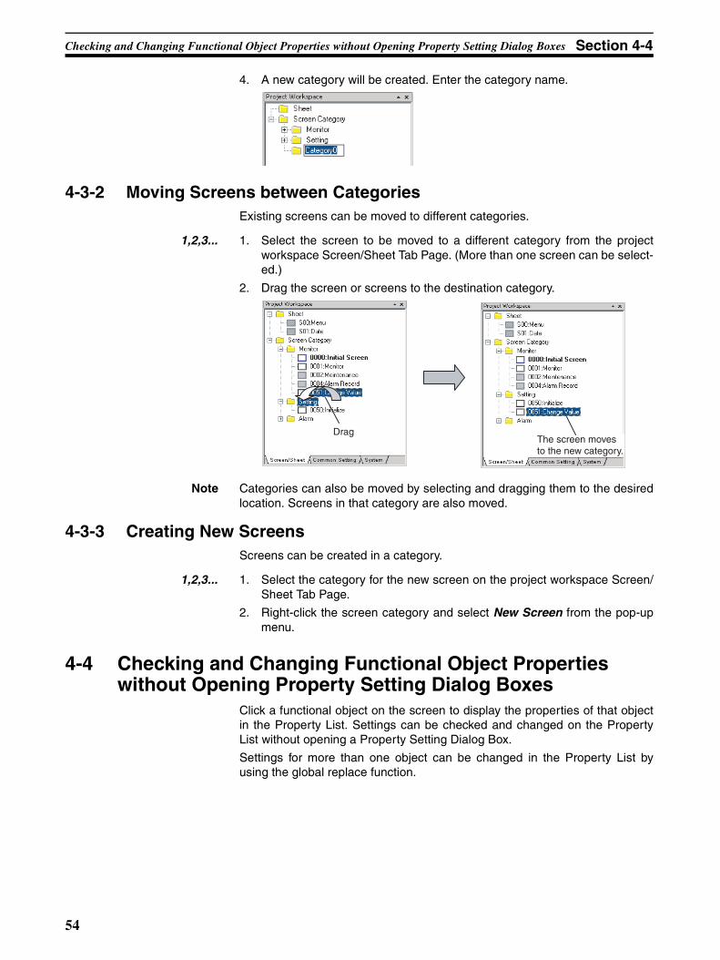
Checking and Changing Functional Object Properties without Opening Property Setting Dialog Boxes Section 4-4
4. A new category will be created. Enter the category name.
4-3-2 Moving Screens between CategoriesExisting screens can be moved to different categories.
1,2,3... 1. Select the screen to be moved to a different category from the projectworkspace Screen/Sheet Tab Page. (More than one screen can be select-ed.)
2. Drag the screen or screens to the destination category.
Note Categories can also be moved by selecting and dragging them to the desiredlocation. Screens in that category are also moved.
4-3-3 Creating New ScreensScreens can be created in a category.
1,2,3... 1. Select the category for the new screen on the project workspace Screen/Sheet Tab Page.
2. Right-click the screen category and select New Screen from the pop-upmenu.
4-4 Checking and Changing Functional Object Properties without Opening Property Setting Dialog Boxes
Click a functional object on the screen to display the properties of that objectin the Property List. Settings can be checked and changed on the PropertyList without opening a Property Setting Dialog Box.
Settings for more than one object can be changed in the Property List byusing the global replace function.
DragThe screen moves to the new category.
54
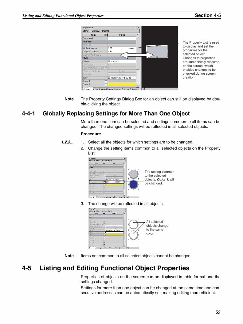
Listing and Editing Functional Object Properties Section 4-5
Note The Property Settings Dialog Box for an object can still be displayed by dou-ble-clicking the object.
4-4-1 Globally Replacing Settings for More Than One ObjectMore than one item can be selected and settings common to all items can bechanged. The changed settings will be reflected in all selected objects.
Procedure
1,2,3... 1. Select all the objects for which settings are to be changed.
2. Change the setting items common to all selected objects on the PropertyList.
3. The change will be reflected in all objects.
Note Items not common to all selected objects cannot be changed.
4-5 Listing and Editing Functional Object PropertiesProperties of objects on the screen can be displayed in table format and thesettings changed.
Settings for more than one object can be changed at the same time and con-secutive addresses can be automatically set, making editing more efficient.
The Property List is used to display and set the properties for the selected object. Changes to properties are immediately reflected on the screen, which enables changes to be checked during screen creation.
The setting common to the selected objects, Color 1, will be changed.
All selected objects change to the same color.
55
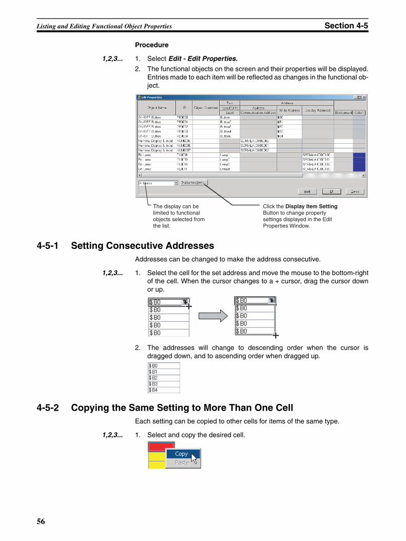
Listing and Editing Functional Object Properties Section 4-5
Procedure
1,2,3... 1. Select Edit - Edit Properties.
2. The functional objects on the screen and their properties will be displayed.Entries made to each item will be reflected as changes in the functional ob-ject.
4-5-1 Setting Consecutive AddressesAddresses can be changed to make the address consecutive.
1,2,3... 1. Select the cell for the set address and move the mouse to the bottom-rightof the cell. When the cursor changes to a + cursor, drag the cursor downor up.
2. The addresses will change to descending order when the cursor isdragged down, and to ascending order when dragged up.
4-5-2 Copying the Same Setting to More Than One CellEach setting can be copied to other cells for items of the same type.
1,2,3... 1. Select and copy the desired cell.
The display can be limited to functional objects selected from the list.
Click the Display Item Setting Button to change property settings displayed in the Edit Properties Window.
56
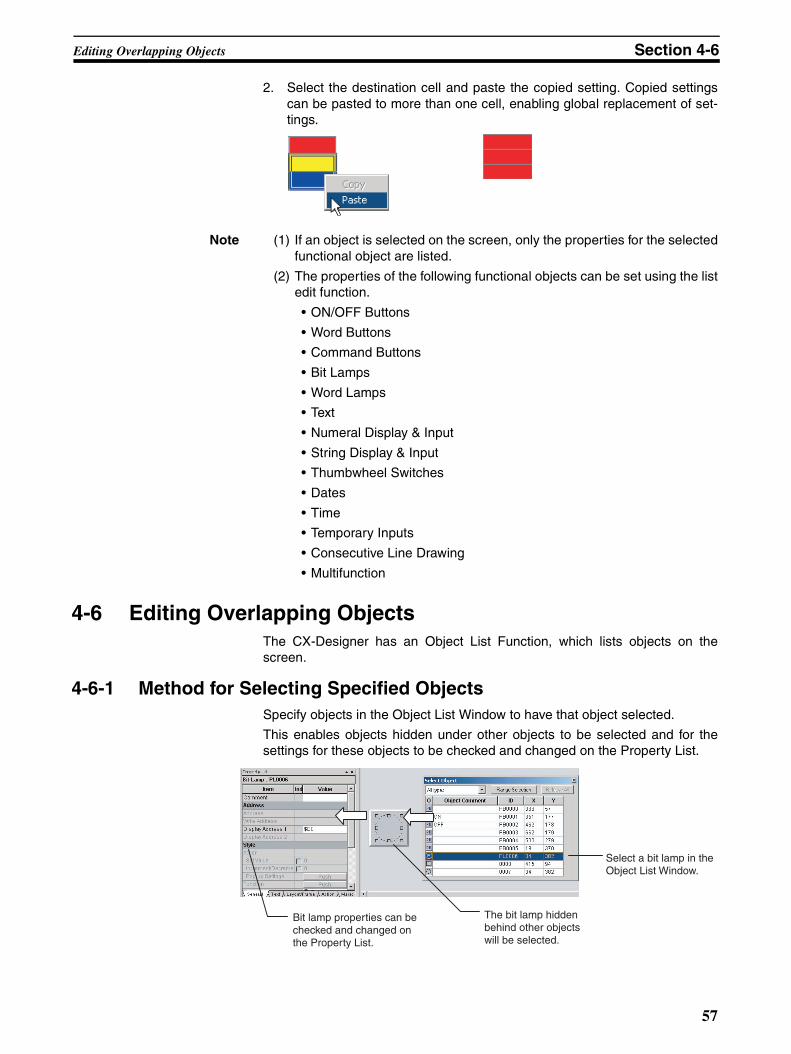
Editing Overlapping Objects Section 4-6
2. Select the destination cell and paste the copied setting. Copied settingscan be pasted to more than one cell, enabling global replacement of set-tings.
Note (1) If an object is selected on the screen, only the properties for the selectedfunctional object are listed.
(2) The properties of the following functional objects can be set using the listedit function.
• ON/OFF Buttons
• Word Buttons
• Command Buttons
• Bit Lamps
• Word Lamps
• Text
• Numeral Display & Input
• String Display & Input
• Thumbwheel Switches
• Dates
• Time
• Temporary Inputs
• Consecutive Line Drawing
• Multifunction
4-6 Editing Overlapping ObjectsThe CX-Designer has an Object List Function, which lists objects on thescreen.
4-6-1 Method for Selecting Specified ObjectsSpecify objects in the Object List Window to have that object selected.
This enables objects hidden under other objects to be selected and for thesettings for these objects to be checked and changed on the Property List.
Select a bit lamp in the Object List Window.
The bit lamp hidden behind other objects will be selected.
Bit lamp properties can be checked and changed on the Property List.
57
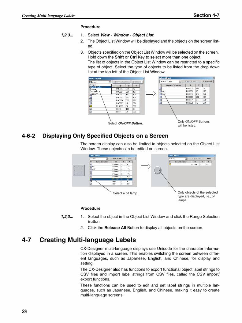
Creating Multi-language Labels Section 4-7
Procedure
1,2,3... 1. Select View - Window - Object List.
2. The Object List Window will be displayed and the objects on the screen list-ed.
3. Objects specified on the Object List Window will be selected on the screen. Hold down the Shift or Ctrl Key to select more than one object. The list of objects in the Object List Window can be restricted to a specifictype of object. Select the type of objects to be listed from the drop downlist at the top left of the Object List Window.
4-6-2 Displaying Only Specified Objects on a ScreenThe screen display can also be limited to objects selected on the Object ListWindow. These objects can be edited on screen.
Procedure
1,2,3... 1. Select the object in the Object List Window and click the Range SelectionButton.
2. Click the Release All Button to display all objects on the screen.
4-7 Creating Multi-language LabelsCX-Designer multi-language displays use Unicode for the character informa-tion displayed in a screen. This enables switching the screen between differ-ent languages, such as Japanese, English, and Chinese, for display andsetting.
The CX-Designer also has functions to export functional object label strings toCSV files and import label strings from CSV files, called the CSV import/export functions.
These functions can be used to edit and set label strings in multiple lan-guages, such as Japanese, English, and Chinese, making it easy to createmulti-language screens.
Select ON/OFF Button. Only ON/OFF Buttons will be listed.
Select a bit lamp. Only objects of the selected type are displayed, i.e., bit lamps.
58
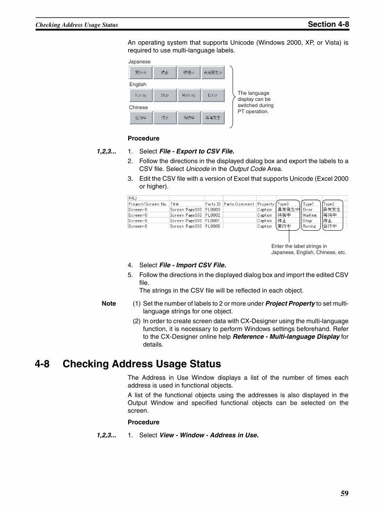
Checking Address Usage Status Section 4-8
An operating system that supports Unicode (Windows 2000, XP, or Vista) isrequired to use multi-language labels.
Procedure
1,2,3... 1. Select File - Export to CSV File.
2. Follow the directions in the displayed dialog box and export the labels to aCSV file. Select Unicode in the Output Code Area.
3. Edit the CSV file with a version of Excel that supports Unicode (Excel 2000or higher).
4. Select File - Import CSV File.
5. Follow the directions in the displayed dialog box and import the edited CSVfile. The strings in the CSV file will be reflected in each object.
Note (1) Set the number of labels to 2 or more under Project Property to set multi-language strings for one object.
(2) In order to create screen data with CX-Designer using the multi-languagefunction, it is necessary to perform Windows settings beforehand. Referto the CX-Designer online help Reference - Multi-language Display fordetails.
4-8 Checking Address Usage StatusThe Address in Use Window displays a list of the number of times eachaddress is used in functional objects.
A list of the functional objects using the addresses is also displayed in theOutput Window and specified functional objects can be selected on thescreen.
Procedure
1,2,3... 1. Select View - Window - Address in Use.
Japanese
English
Chinese
The language display can be switched during PT operation.
Enter the label strings in Japanese, English, Chinese, etc.
59
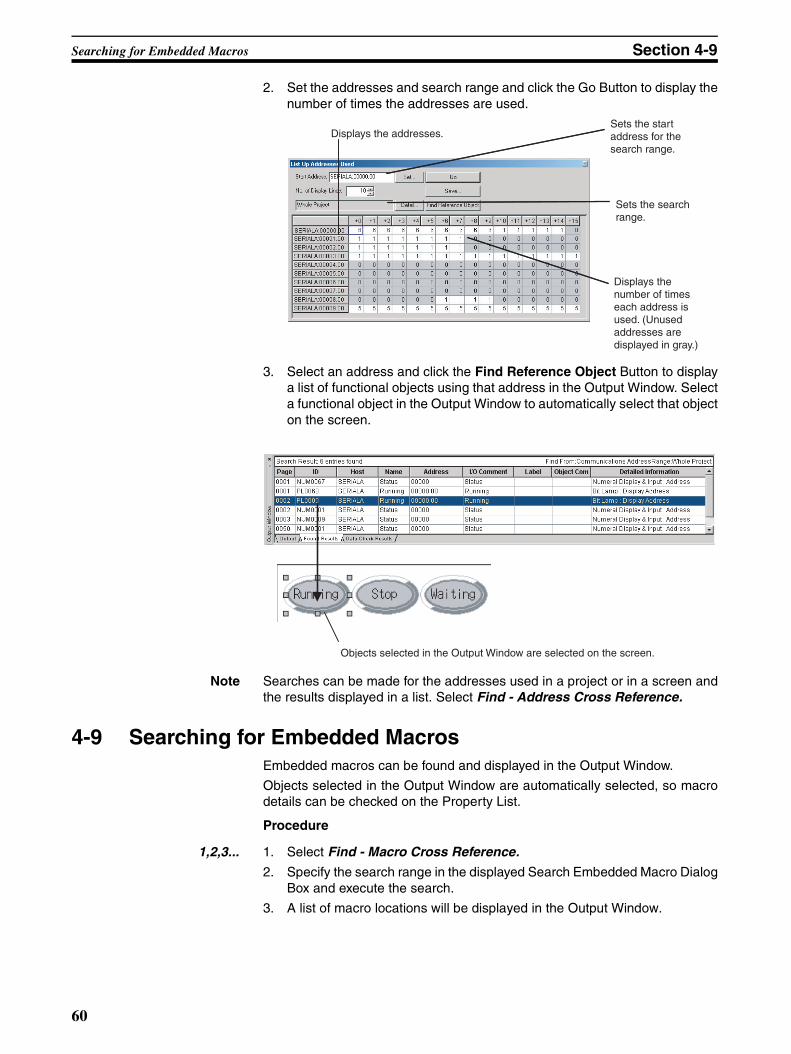
Searching for Embedded Macros Section 4-9
2. Set the addresses and search range and click the Go Button to display thenumber of times the addresses are used.
3. Select an address and click the Find Reference Object Button to displaya list of functional objects using that address in the Output Window. Selecta functional object in the Output Window to automatically select that objecton the screen.
Note Searches can be made for the addresses used in a project or in a screen andthe results displayed in a list. Select Find - Address Cross Reference.
4-9 Searching for Embedded MacrosEmbedded macros can be found and displayed in the Output Window.
Objects selected in the Output Window are automatically selected, so macrodetails can be checked on the Property List.
Procedure
1,2,3... 1. Select Find - Macro Cross Reference.
2. Specify the search range in the displayed Search Embedded Macro DialogBox and execute the search.
3. A list of macro locations will be displayed in the Output Window.
Displays the addresses.
Displays the number of times each address is used. (Unused addresses are displayed in gray.)
Sets the start address for the search range.
Sets the search range.
Objects selected in the Output Window are selected on the screen.
60
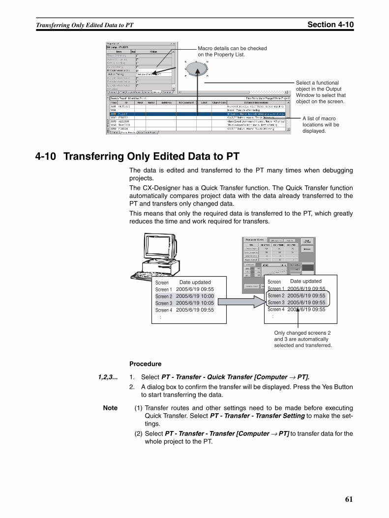
Transferring Only Edited Data to PT Section 4-10
4-10 Transferring Only Edited Data to PTThe data is edited and transferred to the PT many times when debuggingprojects.
The CX-Designer has a Quick Transfer function. The Quick Transfer functionautomatically compares project data with the data already transferred to thePT and transfers only changed data.
This means that only the required data is transferred to the PT, which greatlyreduces the time and work required for transfers.
Procedure
1,2,3... 1. Select PT - Transfer - Quick Transfer [Computer → PT].
2. A dialog box to confirm the transfer will be displayed. Press the Yes Buttonto start transferring the data.
Note (1) Transfer routes and other settings need to be made before executingQuick Transfer. Select PT - Transfer - Transfer Setting to make the set-tings.
(2) Select PT - Transfer - Transfer [Computer → PT] to transfer data for thewhole project to the PT.
Macro details can be checked on the Property List.
Select a functional object in the Output Window to select that object on the screen.
A list of macro locations will be displayed.
Only changed screens 2 and 3 are automatically selected and transferred.
ScreenScreen 1Screen 2Screen 3Screen 4 :
ScreenScreen 1Screen 2Screen 3Screen 4 :
Date updated Date updated
2005/6/19 09:552005/6/19 10:002005/6/19 10:052005/6/19 09:55
2005/6/19 09:552005/6/19 09:552005/6/19 09:552005/6/19 09:55
61
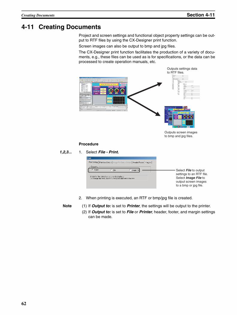
Creating Documents Section 4-11
4-11 Creating DocumentsProject and screen settings and functional object property settings can be out-put to RTF files by using the CX-Designer print function.
Screen images can also be output to bmp and jpg files.
The CX-Designer print function facilitates the production of a variety of docu-ments, e.g., these files can be used as is for specifications, or the data can beprocessed to create operation manuals, etc.
Procedure
1,2,3... 1. Select File - Print.
2. When printing is executed, an RTF or bmp/jpg file is created.
Note (1) If Output to: is set to Printer, the settings will be output to the printer.
(2) If Output to: is set to File or Printer, header, footer, and margin settingscan be made.
Outputs settings data to RTF files.
Outputs screen images to bmp and jpg files.
Select File to output settings to an RTF file. Select Image File to output screen images to a bmp or jpg file.
62
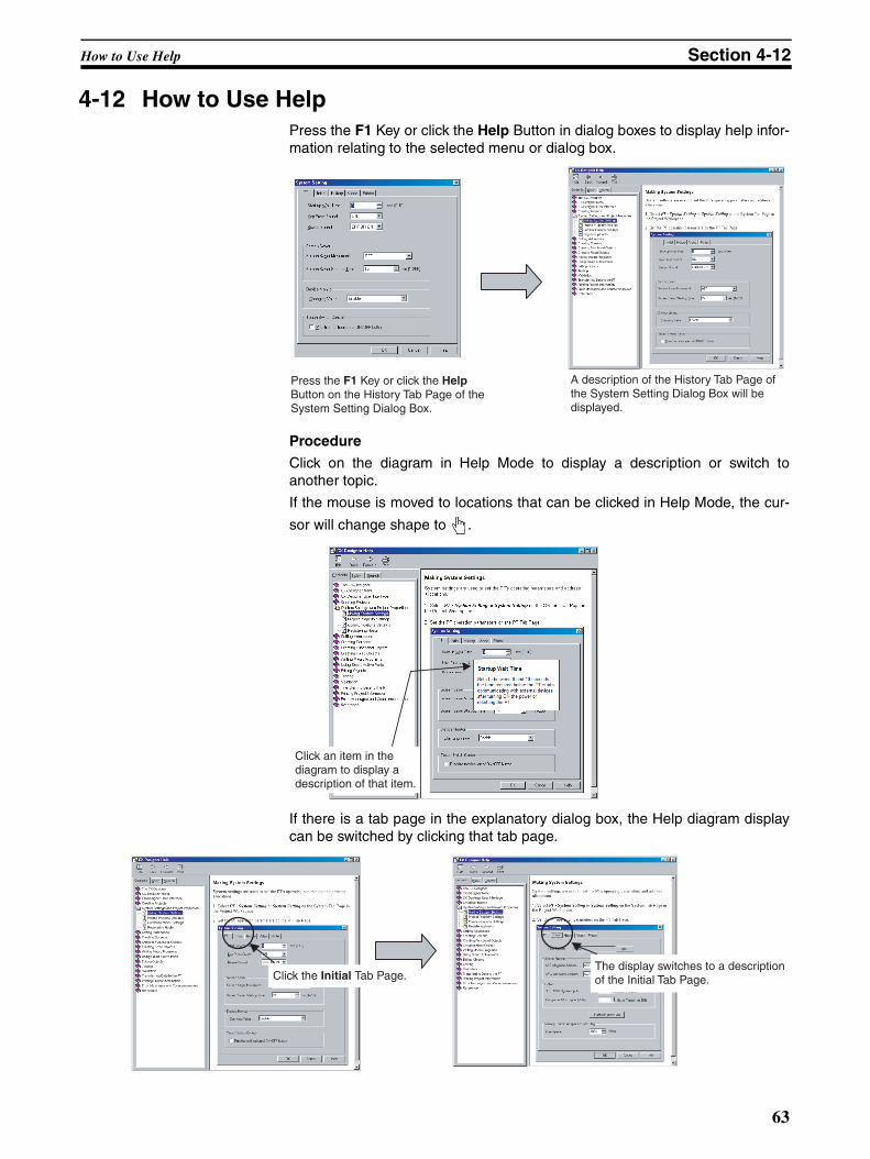
How to Use Help Section 4-12
4-12 How to Use HelpPress the F1 Key or click the Help Button in dialog boxes to display help infor-mation relating to the selected menu or dialog box.
Procedure
Click on the diagram in Help Mode to display a description or switch toanother topic.
If the mouse is moved to locations that can be clicked in Help Mode, the cur-
sor will change shape to .
If there is a tab page in the explanatory dialog box, the Help diagram displaycan be switched by clicking that tab page.
Press the F1 Key or click the Help Button on the History Tab Page of the System Setting Dialog Box.
A description of the History Tab Page of the System Setting Dialog Box will be displayed.
Click an item in the diagram to display a description of that item.
Click the Initial Tab Page. The display switches to a description of the Initial Tab Page.
63
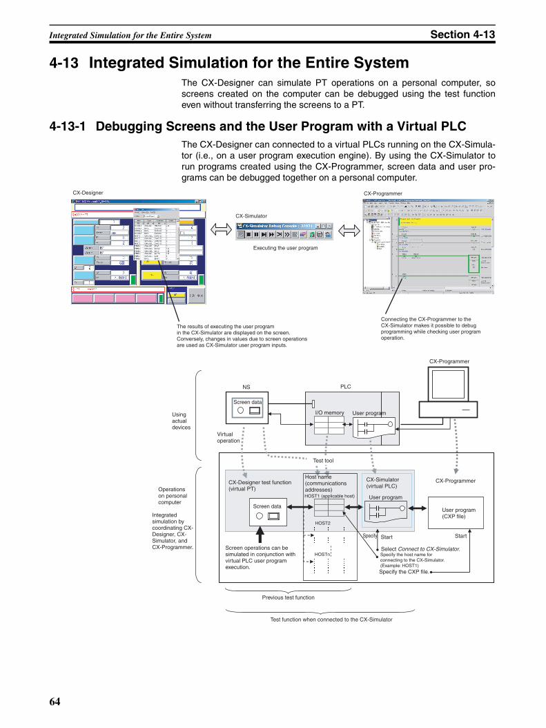
Integrated Simulation for the Entire System Section 4-13
4-13 Integrated Simulation for the Entire SystemThe CX-Designer can simulate PT operations on a personal computer, soscreens created on the computer can be debugged using the test functioneven without transferring the screens to a PT.
4-13-1 Debugging Screens and the User Program with a Virtual PLCThe CX-Designer can connected to a virtual PLCs running on the CX-Simula-tor (i.e., on a user program execution engine). By using the CX-Simulator torun programs created using the CX-Programmer, screen data and user pro-grams can be debugged together on a personal computer.
CX-Designer
Executing the user program
Connecting the CX-Programmer to the CX-Simulator makes it possible to debug programming while checking user program operation.
The results of executing the user program in the CX-Simulator are displayed on the screen. Conversely, changes in values due to screen operations are used as CX-Simulator user program inputs.
CX-Simulator
CX-Programmer
Using actual devices
Operations on personal computer
Integrated simulation by coordinating CX-Designer, CX-Simulator, and CX-Programmer.
NS PLC
CX-Programmer
Screen data
I/O memory User program
CX-ProgrammerCX-Simulator (virtual PLC)
User program
User program (CXP file)
StartStartSpecify
Select Connect to CX-Simulator.
Specify the CXP file.
Specify the host name for connecting to the CX-Simulator. (Example: HOST1)
Previous test function
Screen operations can be simulated in conjunction with virtual PLC user program execution.
Screen data
Test tool
Host name(communications addresses)HOST1 (applicable host)
HOST2
HOSTn
CX-Designer test function (virtual PT)
Test function when connected to the CX-Simulator
Virtual operation
64
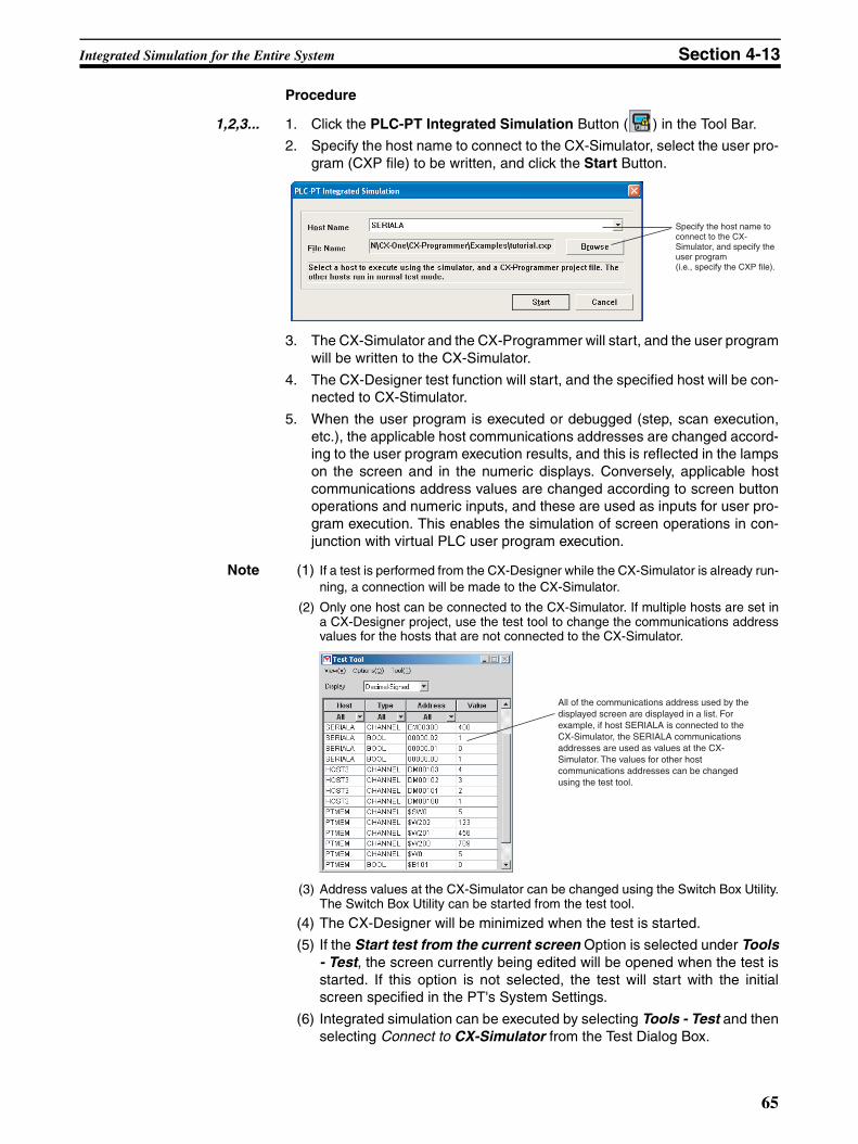
Integrated Simulation for the Entire System Section 4-13
Procedure
1,2,3... 1. Click the PLC-PT Integrated Simulation Button ( ) in the Tool Bar.
2. Specify the host name to connect to the CX-Simulator, select the user pro-gram (CXP file) to be written, and click the Start Button.
3. The CX-Simulator and the CX-Programmer will start, and the user programwill be written to the CX-Simulator.
4. The CX-Designer test function will start, and the specified host will be con-nected to CX-Stimulator.
5. When the user program is executed or debugged (step, scan execution,etc.), the applicable host communications addresses are changed accord-ing to the user program execution results, and this is reflected in the lampson the screen and in the numeric displays. Conversely, applicable hostcommunications address values are changed according to screen buttonoperations and numeric inputs, and these are used as inputs for user pro-gram execution. This enables the simulation of screen operations in con-junction with virtual PLC user program execution.
Note (1) If a test is performed from the CX-Designer while the CX-Simulator is already run-ning, a connection will be made to the CX-Simulator.
(2) Only one host can be connected to the CX-Simulator. If multiple hosts are set ina CX-Designer project, use the test tool to change the communications addressvalues for the hosts that are not connected to the CX-Simulator.
(3) Address values at the CX-Simulator can be changed using the Switch Box Utility.The Switch Box Utility can be started from the test tool.
(4) The CX-Designer will be minimized when the test is started.
(5) If the Start test from the current screen Option is selected under Tools- Test, the screen currently being edited will be opened when the test isstarted. If this option is not selected, the test will start with the initialscreen specified in the PT's System Settings.
(6) Integrated simulation can be executed by selecting Tools - Test and thenselecting Connect to CX-Simulator from the Test Dialog Box.
Specify the host name to connect to the CX-Simulator, and specify the user program (i.e., specify the CXP file).
All of the communications address used by the displayed screen are displayed in a list. For example, if host SERIALA is connected to the CX-Simulator, the SERIALA communications addresses are used as values at the CX-Simulator. The values for other host communications addresses can be changed using the test tool.
65
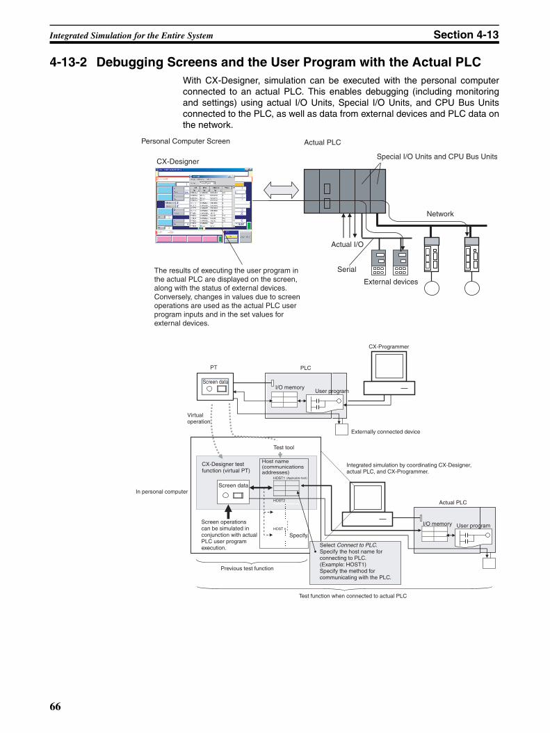
Integrated Simulation for the Entire System Section 4-13
4-13-2 Debugging Screens and the User Program with the Actual PLCWith CX-Designer, simulation can be executed with the personal computerconnected to an actual PLC. This enables debugging (including monitoringand settings) using actual I/O Units, Special I/O Units, and CPU Bus Unitsconnected to the PLC, as well as data from external devices and PLC data onthe network.
The results of executing the user program in the actual PLC are displayed on the screen, along with the status of external devices. Conversely, changes in values due to screen operations are used as the actual PLC user program inputs and in the set values for external devices.
Serial
Actual I/O
Actual PLCPersonal Computer Screen
Special I/O Units and CPU Bus Units
Network
External devices
CX-Designer
HOST1
HOST2
HOST n
PT PLC
Screen data
Virtual operation
In personal computer
Previous test function
Test function when connected to actual PLC
Select Connect to PLC.Specify the host name for connecting to PLC. (Example: HOST1) Specify the method for communicating with the PLC.
Host name (communications addresses)
Test tool
Screen data
CX-Designer test function (virtual PT)
Screen operations can be simulated in conjunction with actual PLC user program execution.
Specify.
Integrated simulation by coordinating CX-Designer, actual PLC, and CX-Programmer.
Actual PLC
I/O memory User program
Externally connected device
CX-Programmer
User programI/O memory
(Applicable host)
66
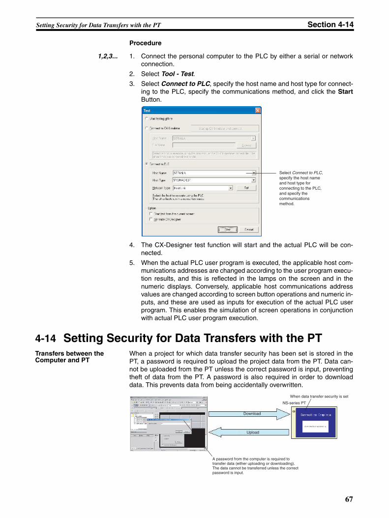
Setting Security for Data Transfers with the PT Section 4-14
Procedure
1,2,3... 1. Connect the personal computer to the PLC by either a serial or networkconnection.
2. Select Tool - Test.
3. Select Connect to PLC, specify the host name and host type for connect-ing to the PLC, specify the communications method, and click the StartButton.
4. The CX-Designer test function will start and the actual PLC will be con-nected.
5. When the actual PLC user program is executed, the applicable host com-munications addresses are changed according to the user program execu-tion results, and this is reflected in the lamps on the screen and in thenumeric displays. Conversely, applicable host communications addressvalues are changed according to screen button operations and numeric in-puts, and these are used as inputs for execution of the actual PLC userprogram. This enables the simulation of screen operations in conjunctionwith actual PLC user program execution.
4-14 Setting Security for Data Transfers with the PTTransfers between the Computer and PT
When a project for which data transfer security has been set is stored in thePT, a password is required to upload the project data from the PT. Data can-not be uploaded from the PT unless the correct password is input, preventingtheft of data from the PT. A password is also required in order to downloaddata. This prevents data from being accidentally overwritten.
Select Connect to PLC, specify the host name and host type for connecting to the PLC, and specify the communications method.
Download
Upload
NS-series PT
A password from the computer is required to transfer data (either uploading or downloading). The data cannot be transferred unless the correct password is input.
When data transfer security is set
67
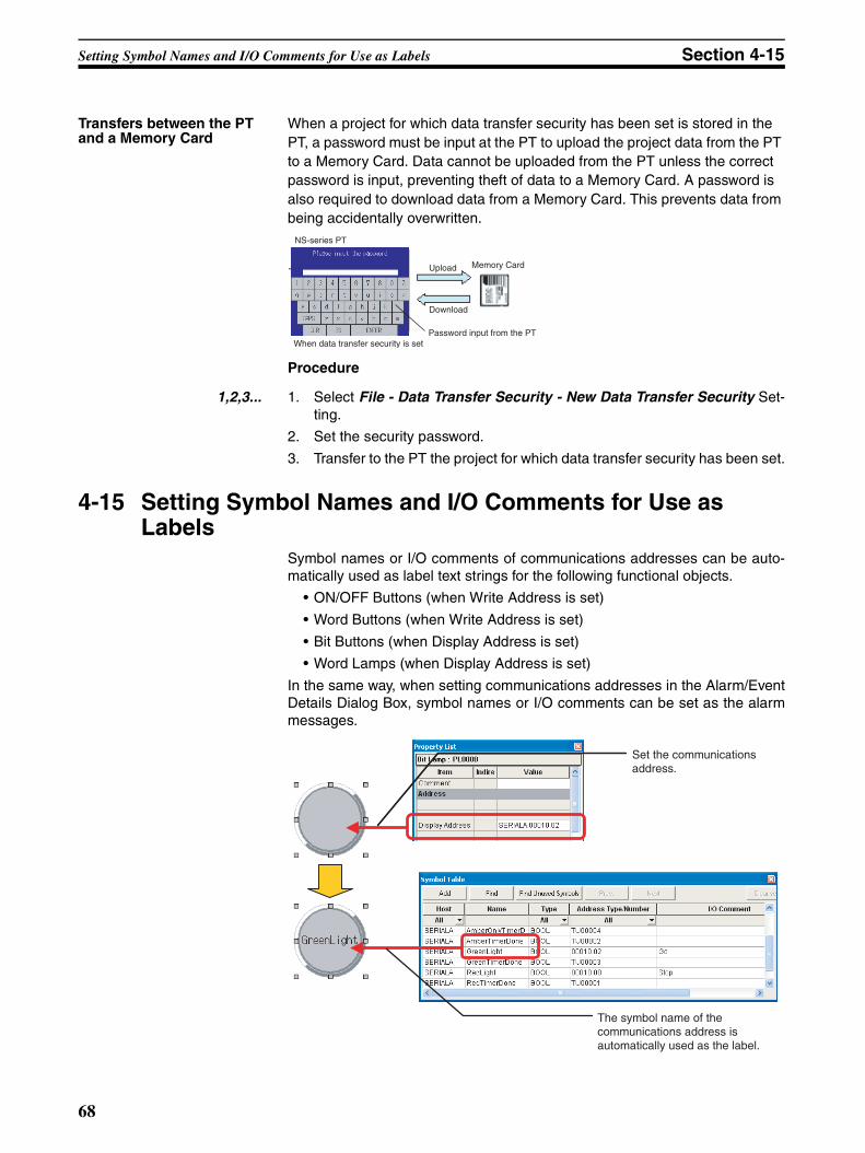
Setting Symbol Names and I/O Comments for Use as Labels Section 4-15
Transfers between the PT and a Memory Card
When a project for which data transfer security has been set is stored in the PT, a password must be input at the PT to upload the project data from the PT to a Memory Card. Data cannot be uploaded from the PT unless the correct password is input, preventing theft of data to a Memory Card. A password is also required to download data from a Memory Card. This prevents data from being accidentally overwritten.
Procedure
1,2,3... 1. Select File - Data Transfer Security - New Data Transfer Security Set-ting.
2. Set the security password.
3. Transfer to the PT the project for which data transfer security has been set.
4-15 Setting Symbol Names and I/O Comments for Use as Labels
Symbol names or I/O comments of communications addresses can be auto-matically used as label text strings for the following functional objects.
• ON/OFF Buttons (when Write Address is set)
• Word Buttons (when Write Address is set)
• Bit Buttons (when Display Address is set)
• Word Lamps (when Display Address is set)
In the same way, when setting communications addresses in the Alarm/EventDetails Dialog Box, symbol names or I/O comments can be set as the alarmmessages.
NS-series PT
Memory CardUpload
Download
Password input from the PTWhen data transfer security is set
Set the communications address.
The symbol name of the communications address is automatically used as the label.
68
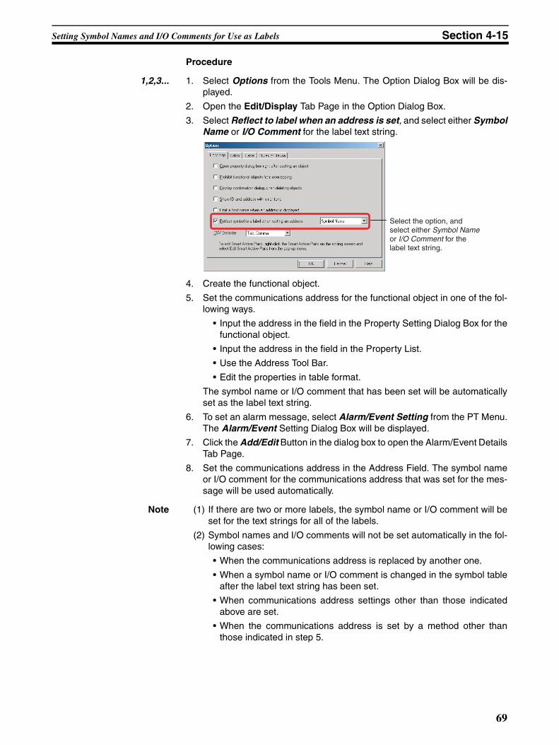
Setting Symbol Names and I/O Comments for Use as Labels Section 4-15
Procedure
1,2,3... 1. Select Options from the Tools Menu. The Option Dialog Box will be dis-played.
2. Open the Edit/Display Tab Page in the Option Dialog Box.
3. Select Reflect to label when an address is set, and select either SymbolName or I/O Comment for the label text string.
4. Create the functional object.
5. Set the communications address for the functional object in one of the fol-lowing ways.
• Input the address in the field in the Property Setting Dialog Box for thefunctional object.
• Input the address in the field in the Property List.
• Use the Address Tool Bar.
• Edit the properties in table format.
The symbol name or I/O comment that has been set will be automaticallyset as the label text string.
6. To set an alarm message, select Alarm/Event Setting from the PT Menu.The Alarm/Event Setting Dialog Box will be displayed.
7. Click the Add/Edit Button in the dialog box to open the Alarm/Event DetailsTab Page.
8. Set the communications address in the Address Field. The symbol nameor I/O comment for the communications address that was set for the mes-sage will be used automatically.
Note (1) If there are two or more labels, the symbol name or I/O comment will beset for the text strings for all of the labels.
(2) Symbol names and I/O comments will not be set automatically in the fol-lowing cases:
• When the communications address is replaced by another one.
• When a symbol name or I/O comment is changed in the symbol tableafter the label text string has been set.
• When communications address settings other than those indicatedabove are set.
• When the communications address is set by a method other thanthose indicated in step 5.
Select the option, and select either Symbol Name or I/O Comment for the label text string.
69
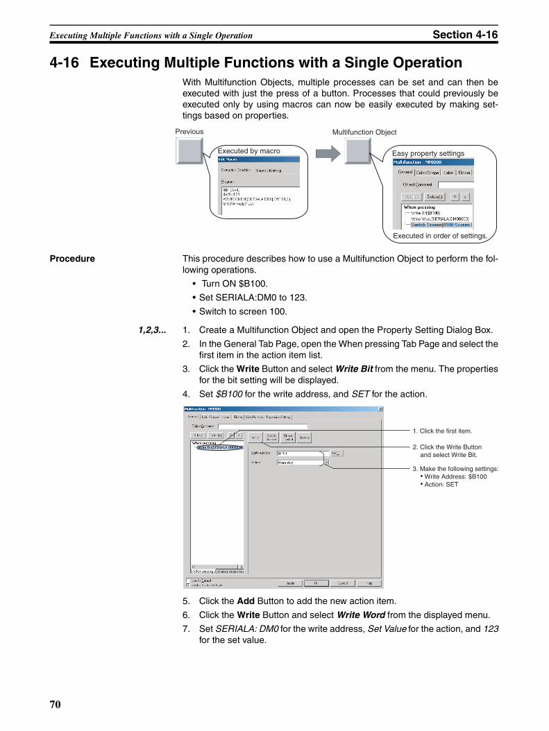
Executing Multiple Functions with a Single Operation Section 4-16
4-16 Executing Multiple Functions with a Single OperationWith Multifunction Objects, multiple processes can be set and can then beexecuted with just the press of a button. Processes that could previously beexecuted only by using macros can now be easily executed by making set-tings based on properties.
Procedure This procedure describes how to use a Multifunction Object to perform the fol-lowing operations.
• Turn ON $B100.
• Set SERIALA:DM0 to 123.
• Switch to screen 100.
1,2,3... 1. Create a Multifunction Object and open the Property Setting Dialog Box.
2. In the General Tab Page, open the When pressing Tab Page and select thefirst item in the action item list.
3. Click the Write Button and select Write Bit from the menu. The propertiesfor the bit setting will be displayed.
4. Set $B100 for the write address, and SET for the action.
5. Click the Add Button to add the new action item.
6. Click the Write Button and select Write Word from the displayed menu.
7. Set SERIALA: DM0 for the write address, Set Value for the action, and 123for the set value.
Easy property settings
Multifunction Object
Executed by macro
Previous
Executed in order of settings.
3. Make the following settings:● Write Address: $B100 ● Action: SET
1. Click the first item.
2. Click the Write Button and select Write Bit.
70
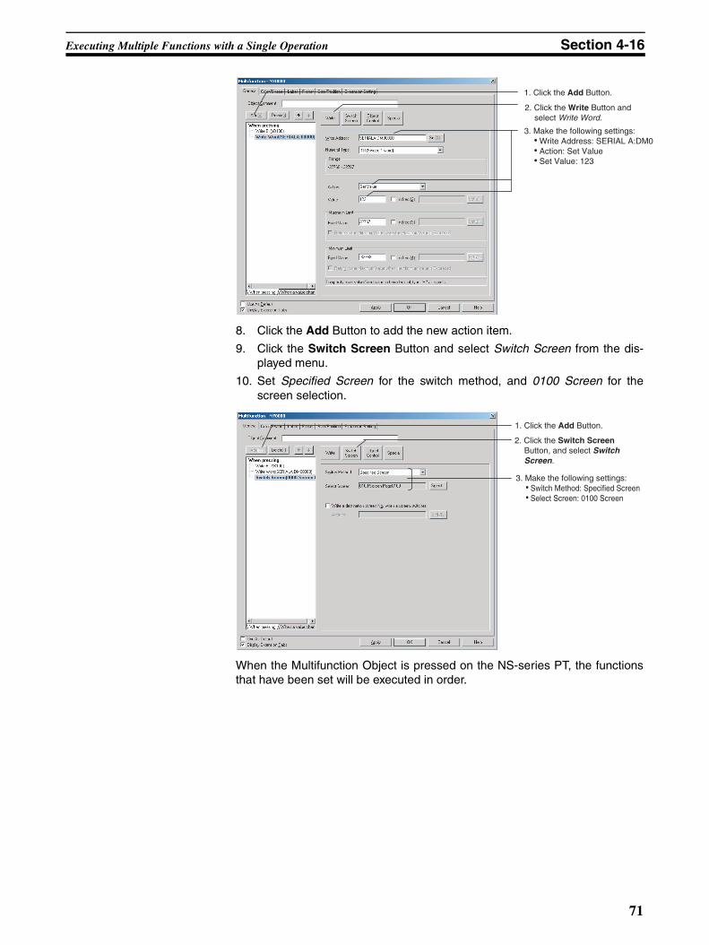
Executing Multiple Functions with a Single Operation Section 4-16
8. Click the Add Button to add the new action item.
9. Click the Switch Screen Button and select Switch Screen from the dis-played menu.
10. Set Specified Screen for the switch method, and 0100 Screen for thescreen selection.
When the Multifunction Object is pressed on the NS-series PT, the functionsthat have been set will be executed in order.
1. Click the Add Button.
2. Click the Write Button and select Write Word.
3. Make the following settings:● Write Address: SERIAL A:DM0 ● Action: Set Value● Set Value: 123
1. Click the Add Button.
3. Make the following settings:● Switch Method: Specified Screen ● Select Screen: 0100 Screen
2. Click the Switch Screen Button, and select Switch Screen.
71
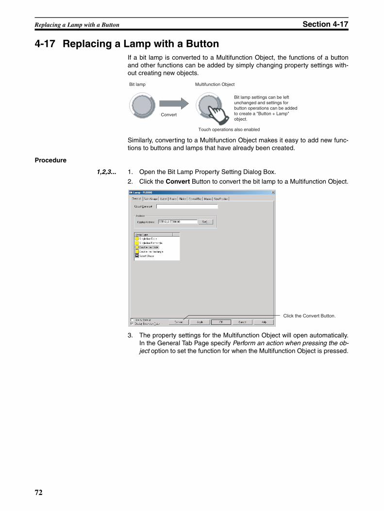
Replacing a Lamp with a Button Section 4-17
4-17 Replacing a Lamp with a ButtonIf a bit lamp is converted to a Multifunction Object, the functions of a buttonand other functions can be added by simply changing property settings with-out creating new objects.
Similarly, converting to a Multifunction Object makes it easy to add new func-tions to buttons and lamps that have already been created.
Procedure
1,2,3... 1. Open the Bit Lamp Property Setting Dialog Box.
2. Click the Convert Button to convert the bit lamp to a Multifunction Object.
3. The property settings for the Multifunction Object will open automatically.In the General Tab Page specify Perform an action when pressing the ob-ject option to set the function for when the Multifunction Object is pressed.
Bit lamp Multifunction Object
Convert
Touch operations also enabled
Bit lamp settings can be left unchanged and settings for button operations can be added to create a "Button + Lamp" object.
Click the Convert Button.
72
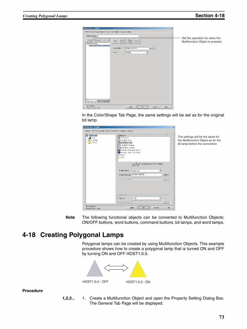
Creating Polygonal Lamps Section 4-18
In the Color/Shape Tab Page, the same settings will be set as for the originalbit lamp.
Note The following functional objects can be converted to Multifunction Objects:ON/OFF buttons, word buttons, command buttons, bit lamps, and word lamps.
4-18 Creating Polygonal LampsPolygonal lamps can be created by using Multifunction Objects. This exampleprocedure shows how to create a polygonal lamp that is turned ON and OFFby turning ON and OFF HOST1:0.0.
Procedure
1,2,3... 1. Create a Multifunction Object and open the Property Setting Dialog Box.The General Tab Page will be displayed.
Set the operation for when the Multifunction Object is pressed.
The settings will be the same for the Multifunction Object as for the bit lamp before the conversion.
HOST1:0.0 : OFF HOST1:0.0 : ON
73
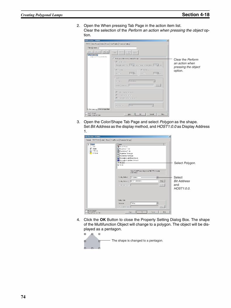
Creating Polygonal Lamps Section 4-18
2. Open the When pressing Tab Page in the action item list.Clear the selection of the Perform an action when pressing the object op-tion.
3. Open the Color/Shape Tab Page and select Polygon as the shape.Set Bit Address as the display method, and HOST1:0.0 as Display Address1.
4. Click the OK Button to close the Property Setting Dialog Box. The shapeof the Multifunction Object will change to a polygon. The object will be dis-played as a pentagon.
Clear the Perform an action when pressing the object option.
Select Polygon.
Select Bit Address and HOST1:0.0.
The shape is changed to a pentagon.
74
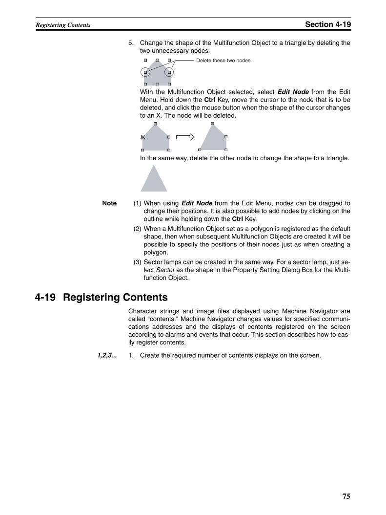
Registering Contents Section 4-19
5. Change the shape of the Multifunction Object to a triangle by deleting thetwo unnecessary nodes.
With the Multifunction Object selected, select Edit Node from the EditMenu. Hold down the Ctrl Key, move the cursor to the node that is to bedeleted, and click the mouse button when the shape of the cursor changesto an X. The node will be deleted.
In the same way, delete the other node to change the shape to a triangle.
Note (1) When using Edit Node from the Edit Menu, nodes can be dragged tochange their positions. It is also possible to add nodes by clicking on theoutline while holding down the Ctrl Key.
(2) When a Multifunction Object set as a polygon is registered as the defaultshape, then when subsequent Multifunction Objects are created it will bepossible to specify the positions of their nodes just as when creating apolygon.
(3) Sector lamps can be created in the same way. For a sector lamp, just se-lect Sector as the shape in the Property Setting Dialog Box for the Multi-function Object.
4-19 Registering ContentsCharacter strings and image files displayed using Machine Navigator arecalled "contents." Machine Navigator changes values for specified communi-cations addresses and the displays of contents registered on the screenaccording to alarms and events that occur. This section describes how to eas-ily register contents.
1,2,3... 1. Create the required number of contents displays on the screen.
Delete these two nodes.
75
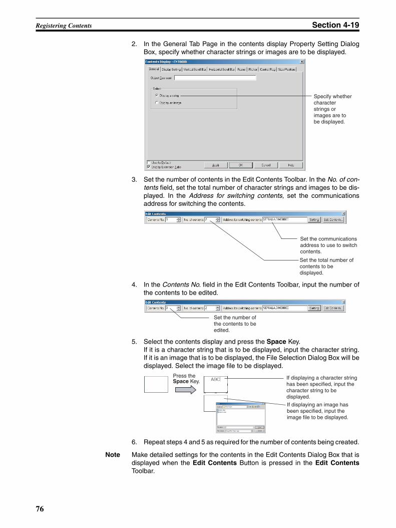
Registering Contents Section 4-19
2. In the General Tab Page in the contents display Property Setting DialogBox, specify whether character strings or images are to be displayed.
3. Set the number of contents in the Edit Contents Toolbar. In the No. of con-tents field, set the total number of character strings and images to be dis-played. In the Address for switching contents, set the communicationsaddress for switching the contents.
4. In the Contents No. field in the Edit Contents Toolbar, input the number ofthe contents to be edited.
5. Select the contents display and press the Space Key. If it is a character string that is to be displayed, input the character string.If it is an image that is to be displayed, the File Selection Dialog Box will bedisplayed. Select the image file to be displayed.
6. Repeat steps 4 and 5 as required for the number of contents being created.
Note Make detailed settings for the contents in the Edit Contents Dialog Box that isdisplayed when the Edit Contents Button is pressed in the Edit ContentsToolbar.
Specify whether character strings or images are to be displayed.
Set the communications address to use to switch contents.
Set the total number of contents to be displayed.
Set the number of the contents to be edited.
If displaying a character string has been specified, input the character string to be displayed.
If displaying an image has been specified, input the image file to be displayed.
Press the Space Key.
76
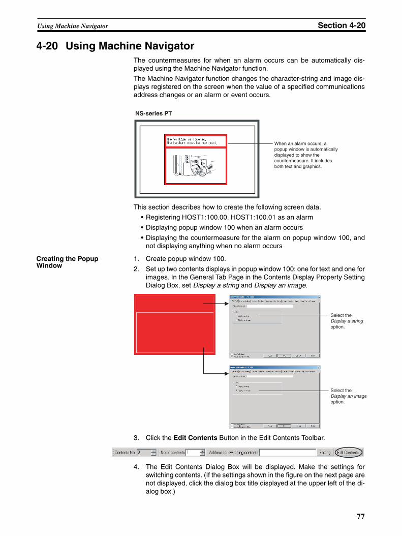
Using Machine Navigator Section 4-20
4-20 Using Machine NavigatorThe countermeasures for when an alarm occurs can be automatically dis-played using the Machine Navigator function.
The Machine Navigator function changes the character-string and image dis-plays registered on the screen when the value of a specified communicationsaddress changes or an alarm or event occurs.
This section describes how to create the following screen data.
• Registering HOST1:100.00, HOST1:100.01 as an alarm
• Displaying popup window 100 when an alarm occurs
• Displaying the countermeasure for the alarm on popup window 100, andnot displaying anything when no alarm occurs
Creating the Popup Window
1. Create popup window 100.
2. Set up two contents displays in popup window 100: one for text and one forimages. In the General Tab Page in the Contents Display Property SettingDialog Box, set Display a string and Display an image.
3. Click the Edit Contents Button in the Edit Contents Toolbar.
4. The Edit Contents Dialog Box will be displayed. Make the settings forswitching contents. (If the settings shown in the figure on the next page arenot displayed, click the dialog box title displayed at the upper left of the di-alog box.)
NS-series PT
When an alarm occurs, a popup window is automatically displayed to show the countermeasure. It includes both text and graphics.
Select the Display a string option.
Select the Display an imageoption.
77
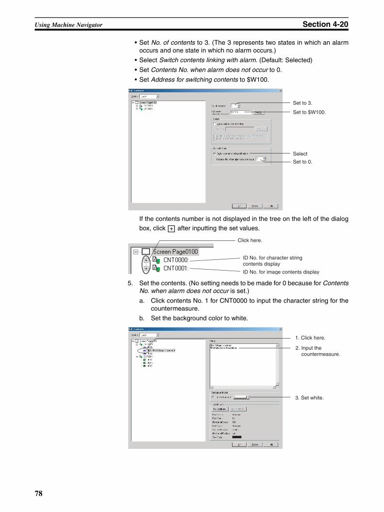
Using Machine Navigator Section 4-20
• Set No. of contents to 3. (The 3 represents two states in which an alarmoccurs and one state in which no alarm occurs.)
• Select Switch contents linking with alarm. (Default: Selected)
• Set Contents No. when alarm does not occur to 0.
• Set Address for switching contents to $W100.
If the contents number is not displayed in the tree on the left of the dialog
box, click after inputting the set values.
5. Set the contents. (No setting needs to be made for 0 because for ContentsNo. when alarm does not occur is set.)
a. Click contents No. 1 for CNT0000 to input the character string for thecountermeasure.
b. Set the background color to white.
Set to 3.
Set to $W100.
Select
Set to 0.
ID No. for character string contents display
ID No. for image contents display
Click here.
1. Click here.
3. Set white.
2. Input the countermeasure.
78
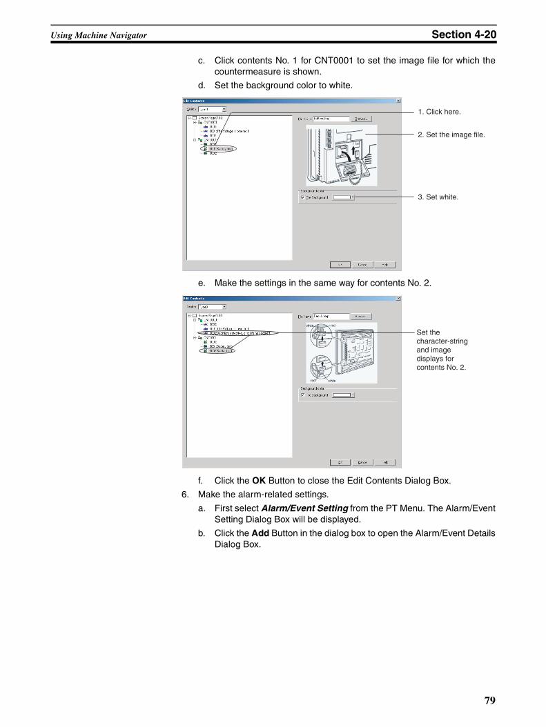
Using Machine Navigator Section 4-20
c. Click contents No. 1 for CNT0001 to set the image file for which thecountermeasure is shown.
d. Set the background color to white.
e. Make the settings in the same way for contents No. 2.
f. Click the OK Button to close the Edit Contents Dialog Box.
6. Make the alarm-related settings.
a. First select Alarm/Event Setting from the PT Menu. The Alarm/EventSetting Dialog Box will be displayed.
b. Click the Add Button in the dialog box to open the Alarm/Event DetailsDialog Box.
1. Click here.
2. Set the image file.
3. Set white.
Set the character-string and image displays for contents No. 2.
79
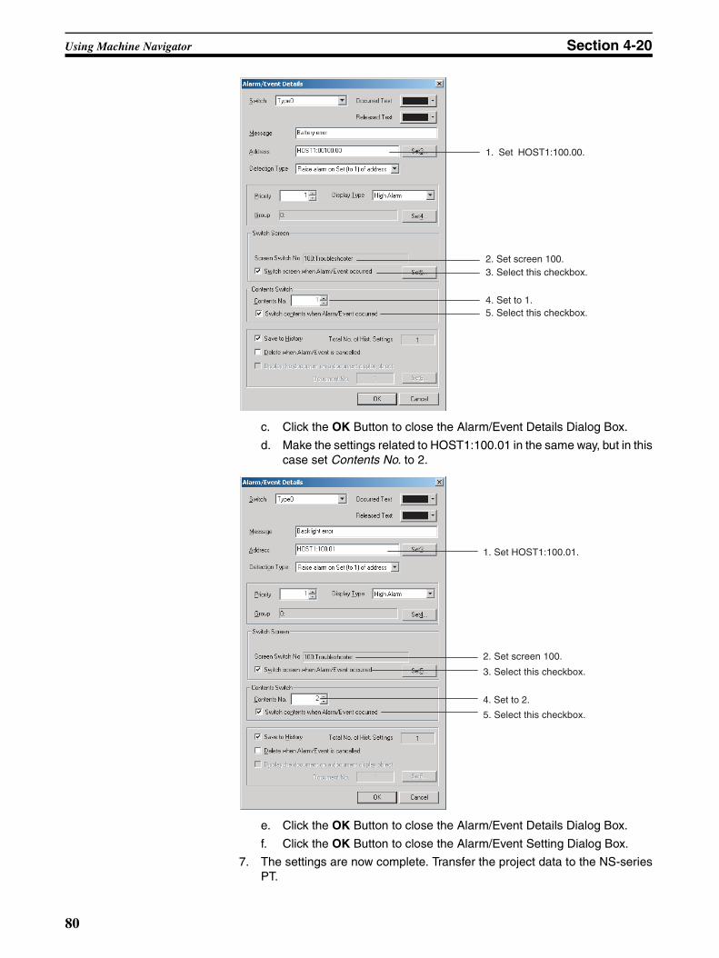
Using Machine Navigator Section 4-20
c. Click the OK Button to close the Alarm/Event Details Dialog Box.
d. Make the settings related to HOST1:100.01 in the same way, but in thiscase set Contents No. to 2.
e. Click the OK Button to close the Alarm/Event Details Dialog Box.
f. Click the OK Button to close the Alarm/Event Setting Dialog Box.
7. The settings are now complete. Transfer the project data to the NS-seriesPT.
1. Set HOST1:100.00.
2. Set screen 100.
4. Set to 1.
3. Select this checkbox.
5. Select this checkbox.
1. Set HOST1:100.01.
3. Select this checkbox.
2. Set screen 100.
5. Select this checkbox.
4. Set to 2.
80
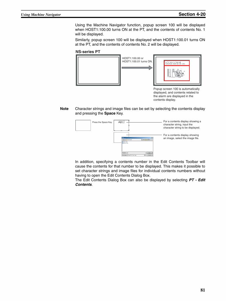
Using Machine Navigator Section 4-20
Using the Machine Navigator function, popup screen 100 will be displayedwhen HOST1:100.00 turns ON at the PT, and the contents of contents No. 1will be displayed.
Similarly, popup screen 100 will be displayed when HOST1:100.01 turns ONat the PT, and the contents of contents No. 2 will be displayed.
Note Character strings and image files can be set by selecting the contents displayand pressing the Space Key.
In addition, specifying a contents number in the Edit Contents Toolbar willcause the contents for that number to be displayed. This makes it possible toset character strings and image files for individual contents numbers withouthaving to open the Edit Contents Dialog Box.The Edit Contents Dialog Box can also be displayed by selecting PT - EditContents.
NS-series PT
HOST1:100.00 or HOST1:100.01 turns ON.
Popup screen 100 is automatically displayed, and contents related to the alarm are displayed in the contents display.
Press the Space Key. For a contents display showing a character string, input the character string to be displayed.
For a contents display showing an image, select the image file.
81

Using Machine Navigator Section 4-20
82
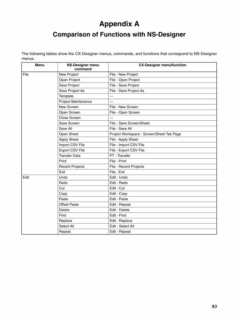
Appendix AComparison of Functions with NS-Designer
The following tables show the CX-Designer menus, commands, and functions that correspond to NS-Designermenus.
Menu NS-Designer menu command
CX-Designer menu/function
File New Project File - New Project
Open Project File - Open Project
Save Project File - Save Project
Save Project As File - Save Project As
Template ---
Project Maintenance ---
New Screen File - New Screen
Open Screen File - Open Screen
Close Screen ---
Save Screen File - Save Screen/Sheet
Save All File - Save All
Open Sheet Project Workspace - Screen/Sheet Tab Page
Apply Sheet File - Apply Sheet
Import CSV File File - Import CSV File
Export CSV File File - Export CSV File
Transfer Data PT - Transfer
Print File - Print
Recent Projects File - Recent Projects
Exit File - Exit
Edit Undo Edit - Undo
Redo Edit - Redo
Cut Edit - Cut
Copy Edit - Copy
Paste Edit - Paste
Offset Paste Edit - Repeat
Delete Edit - Delete
Find Edit - Find
Replace Edit - Replace
Select All Edit - Select All
Repeat Edit - Repeat
83
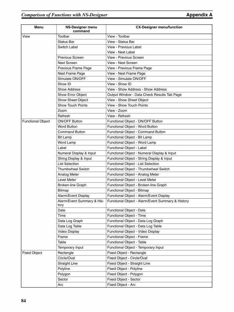
Comparison of Functions with NS-Designer Appendix A
View Toolbar View - Toolbar
Status Bar View - Status Bar
Switch Label View - Previous Label
View - Next Label
Previous Screen View - Previous Screen
Next Screen View - Next Screen
Previous Frame Page View - Previous Frame Page
Next Frame Page View - Next Frame Page
Simulate ON/OFF View - Simulate ON/OFF
Show ID View - Show ID
Show Address View - Show Address - Show Address
Show Error Object Output Window - Data Check Results Tab Page
Show Sheet Object View - Show Sheet Object
Show Touch Points View - Show Touch Points
Zoom View - Zoom
Refresh View - Refresh
Functional Object ON/OFF Button Functional Object - ON/OFF Button
Word Button Functional Object - Word Button
Command Button Functional Object - Command Button
Bit Lamp Functional Object - Bit Lamp
Word Lamp Functional Object - Word Lamp
Label Functional Object - Label
Numeral Display & Input Functional Object - Numeral Display & Input
String Display & Input Functional Object - String Display & Input
List Selection Functional Object - List Selection
Thumbwheel Switch Functional Object - Thumbwheel Switch
Analog Meter Functional Object - Analog Meter
Level Meter Functional Object - Level Meter
Broken-line Graph Functional Object - Broken-line Graph
Bitmap Functional Object - Bitmap
Alarm/Event Display Functional Object - Alarm/Event Display
Alarm/Event Summary & His-tory
Functional Object - Alarm/Event Summary & History
Date Functional Object - Date
Time Functional Object - Time
Data Log Graph Functional Object - Data Log Graph
Data Log Table Functional Object - Data Log Table
Video Display Functional Object - Video Display
Frame Functional Object - Frame
Table Functional Object - Table
Temporary Input Functional Object - Temporary Input
Fixed Object Rectangle Fixed Object - Rectangle
Circle/Oval Fixed Object - Circle/Oval
Straight Line Fixed Object - Straight Line
Polyline Fixed Object - Polyline
Polygon Fixed Object - Polygon
Sector Fixed Object - Sector
Arc Fixed Object - Arc
Menu NS-Designer menu command
CX-Designer menu/function
84
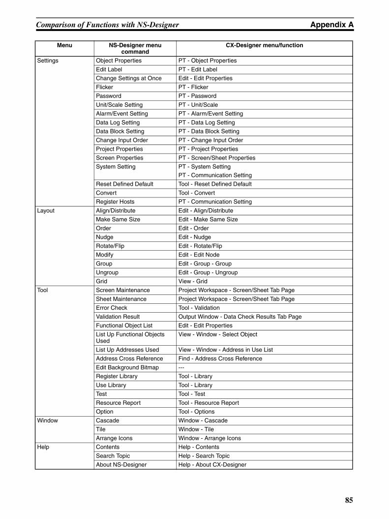
Comparison of Functions with NS-Designer Appendix A
Settings Object Properties PT - Object Properties
Edit Label PT - Edit Label
Change Settings at Once Edit - Edit Properties
Flicker PT - Flicker
Password PT - Password
Unit/Scale Setting PT - Unit/Scale
Alarm/Event Setting PT - Alarm/Event Setting
Data Log Setting PT - Data Log Setting
Data Block Setting PT - Data Block Setting
Change Input Order PT - Change Input Order
Project Properties PT - Project Properties
Screen Properties PT - Screen/Sheet Properties
System Setting PT - System Setting
PT - Communication Setting
Reset Defined Default Tool - Reset Defined Default
Convert Tool - Convert
Register Hosts PT - Communication Setting
Layout Align/Distribute Edit - Align/Distribute
Make Same Size Edit - Make Same Size
Order Edit - Order
Nudge Edit - Nudge
Rotate/Flip Edit - Rotate/Flip
Modify Edit - Edit Node
Group Edit - Group - Group
Ungroup Edit - Group - Ungroup
Grid View - Grid
Tool Screen Maintenance Project Workspace - Screen/Sheet Tab Page
Sheet Maintenance Project Workspace - Screen/Sheet Tab Page
Error Check Tool - Validation
Validation Result Output Window - Data Check Results Tab Page
Functional Object List Edit - Edit Properties
List Up Functional Objects Used
View - Window - Select Object
List Up Addresses Used View - Window - Address in Use List
Address Cross Reference Find - Address Cross Reference
Edit Background Bitmap ---
Register Library Tool - Library
Use Library Tool - Library
Test Tool - Test
Resource Report Tool - Resource Report
Option Tool - Options
Window Cascade Window - Cascade
Tile Window - Tile
Arrange Icons Window - Arrange Icons
Help Contents Help - Contents
Search Topic Help - Search Topic
About NS-Designer Help - About CX-Designer
Menu NS-Designer menu command
CX-Designer menu/function
85

Comparison of Functions with NS-Designer Appendix A
86
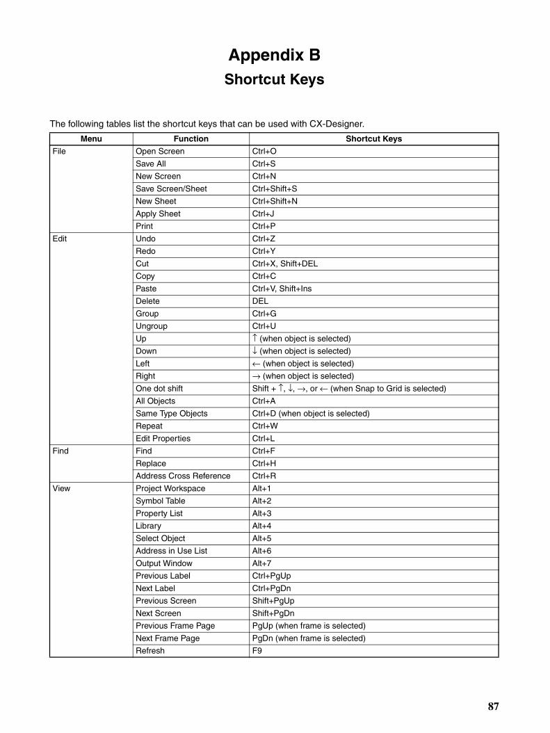
Appendix BShortcut Keys
The following tables list the shortcut keys that can be used with CX-Designer.
Menu Function Shortcut Keys
File Open Screen Ctrl+O
Save All Ctrl+S
New Screen Ctrl+N
Save Screen/Sheet Ctrl+Shift+S
New Sheet Ctrl+Shift+N
Apply Sheet Ctrl+J
Print Ctrl+P
Edit Undo Ctrl+Z
Redo Ctrl+Y
Cut Ctrl+X, Shift+DEL
Copy Ctrl+C
Paste Ctrl+V, Shift+Ins
Delete DEL
Group Ctrl+G
Ungroup Ctrl+U
Up ↑ (when object is selected)
Down ↓ (when object is selected)
Left ← (when object is selected)
Right → (when object is selected)
One dot shift Shift + ↑, ↓, →, or ← (when Snap to Grid is selected)
All Objects Ctrl+A
Same Type Objects Ctrl+D (when object is selected)
Repeat Ctrl+W
Edit Properties Ctrl+L
Find Find Ctrl+F
Replace Ctrl+H
Address Cross Reference Ctrl+R
View Project Workspace Alt+1
Symbol Table Alt+2
Property List Alt+3
Library Alt+4
Select Object Alt+5
Address in Use List Alt+6
Output Window Alt+7
Previous Label Ctrl+PgUp
Next Label Ctrl+PgDn
Previous Screen Shift+PgUp
Next Screen Shift+PgDn
Previous Frame Page PgUp (when frame is selected)
Next Frame Page PgDn (when frame is selected)
Refresh F9
87
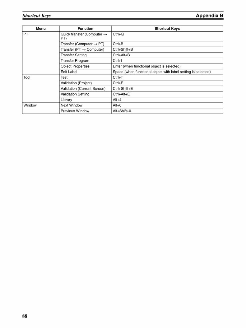
Shortcut Keys Appendix B
PT Quick transfer (Computer → PT)
Ctrl+Q
Transfer (Computer → PT) Ctrl+B
Transfer (PT → Computer) Ctrl+Shift+B
Transfer Setting Ctrl+Alt+B
Transfer Program Ctrl+I
Object Properties Enter (when functional object is selected)
Edit Label Space (when functional object with label setting is selected)
Tool Test Ctrl+T
Validation (Project) Ctrl+E
Validation (Current Screen) Ctrl+Shift+E
Validation Setting Ctrl+Alt+E
Library Alt+4
Window Next Window Alt+0
Previous Window Alt+Shift+0
Menu Function Shortcut Keys
88
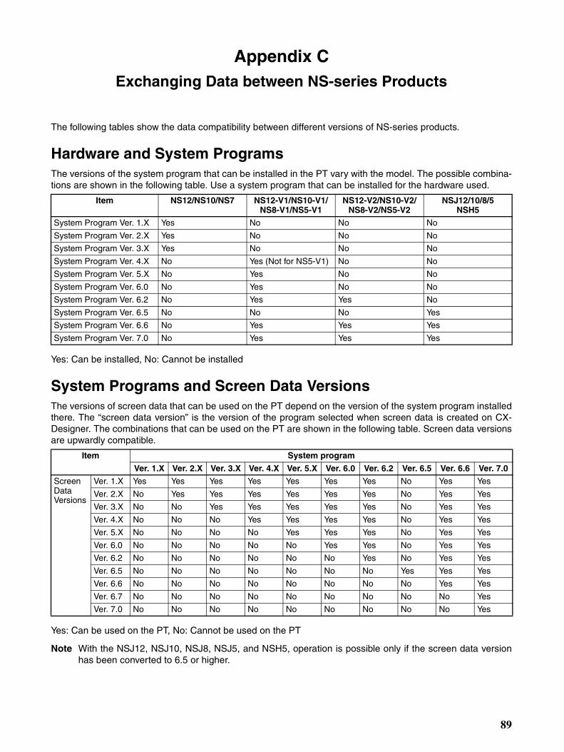
Appendix CExchanging Data between NS-series Products
The following tables show the data compatibility between different versions of NS-series products.
Hardware and System ProgramsThe versions of the system program that can be installed in the PT vary with the model. The possible combina-tions are shown in the following table. Use a system program that can be installed for the hardware used.
Yes: Can be installed, No: Cannot be installed
System Programs and Screen Data VersionsThe versions of screen data that can be used on the PT depend on the version of the system program installedthere. The “screen data version” is the version of the program selected when screen data is created on CX-Designer. The combinations that can be used on the PT are shown in the following table. Screen data versionsare upwardly compatible.
Yes: Can be used on the PT, No: Cannot be used on the PT
Note With the NSJ12, NSJ10, NSJ8, NSJ5, and NSH5, operation is possible only if the screen data versionhas been converted to 6.5 or higher.
Item NS12/NS10/NS7 NS12-V1/NS10-V1/NS8-V1/NS5-V1
NS12-V2/NS10-V2/NS8-V2/NS5-V2
NSJ12/10/8/5 NSH5
System Program Ver. 1.X Yes No No No
System Program Ver. 2.X Yes No No No
System Program Ver. 3.X Yes No No No
System Program Ver. 4.X No Yes (Not for NS5-V1) No No
System Program Ver. 5.X No Yes No No
System Program Ver. 6.0 No Yes No No
System Program Ver. 6.2 No Yes Yes No
System Program Ver. 6.5 No No No Yes
System Program Ver. 6.6 No Yes Yes Yes
System Program Ver. 7.0 No Yes Yes Yes
Item System program
Ver. 1.X Ver. 2.X Ver. 3.X Ver. 4.X Ver. 5.X Ver. 6.0 Ver. 6.2 Ver. 6.5 Ver. 6.6 Ver. 7.0
Screen Data Versions
Ver. 1.X Yes Yes Yes Yes Yes Yes Yes No Yes Yes
Ver. 2.X No Yes Yes Yes Yes Yes Yes No Yes Yes
Ver. 3.X No No Yes Yes Yes Yes Yes No Yes Yes
Ver. 4.X No No No Yes Yes Yes Yes No Yes Yes
Ver. 5.X No No No No Yes Yes Yes No Yes Yes
Ver. 6.0 No No No No No Yes Yes No Yes Yes
Ver. 6.2 No No No No No No Yes No Yes Yes
Ver. 6.5 No No No No No No No Yes Yes Yes
Ver. 6.6 No No No No No No No No Yes Yes
Ver. 6.7 No No No No No No No No No Yes
Ver. 7.0 No No No No No No No No No Yes
89
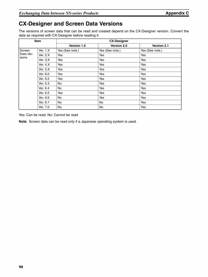
Exchanging Data between NS-series Products Appendix C
CX-Designer and Screen Data VersionsThe versions of screen data that can be read and created depend on the CX-Designer version. Convert thedata as required with CX-Designer before reading it.
Yes: Can be read, No: Cannot be read
Note Screen data can be read only if a Japanese operating system is used.
Item CX-Designer
Version 1.0 Version 2.0 Version 2.1
Screen Data Ver-sions
Ver. 1.X Yes (See note.) Yes (See note.) Yes (See note.)
Ver. 2.X Yes Yes Yes
Ver. 3.X Yes Yes Yes
Ver. 4.X Yes Yes Yes
Ver. 5.X Yes Yes Yes
Ver. 6.0 Yes Yes Yes
Ver. 6.2 Yes Yes Yes
Ver. 6.3 No Yes Yes
Ver. 6.4 No Yes Yes
Ver. 6.5 Yes Yes Yes
Ver. 6.6 No Yes Yes
Ver. 6.7 No No Yes
Ver. 7.0 No No Yes
90
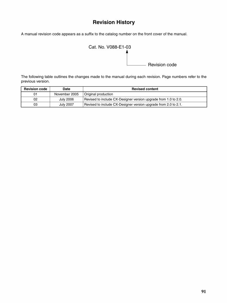
Revision History
A manual revision code appears as a suffix to the catalog number on the front cover of the manual.
The following table outlines the changes made to the manual during each revision. Page numbers refer to theprevious version.
Revision code Date Revised content
01 November 2005 Original production
02 July 2006 Revised to include CX-Designer version upgrade from 1.0 to 2.0.
03 July 2007 Revised to include CX-Designer version upgrade from 2.0 to 2.1.
Cat. No. V088-E1-03
Revision code
91

Revision History
92