
Users Manual for the CL-system - CMT Level Control Systems ...cmtbv.nl/PDF/CL totaal ENG...
27
Users Manual for the CL-system Electronic overfill protection with optional level measurement for LPG storage tanks Version: 2.1 Date: 09.12.2003 Product: CL Model/type: deliveries as of July 2003 CMT Manufacturing BV Hakselseweg 50 NL-6713 KW EDE The Netherlands Telephone: +31 318 619138 Fax: +31 318 650036 E-mail: [email protected]
Transcript of Users Manual for the CL-system - CMT Level Control Systems ...cmtbv.nl/PDF/CL totaal ENG...

Users Manual for the
CL-system
Electronic overfill protection with optional level measurement for LPG storage tanks
Version: 2.1 Date: 09.12.2003 Product: CL Model/type: deliveries as of July 2003 CMT Manufacturing BV Hakselseweg 50 NL-6713 KW EDE The Netherlands Telephone: +31 318 619138 Fax: +31 318 650036 E-mail: [email protected]
2
Contents Foreword .................................................................................................................................................. 3 1. Introduction.................................................................................................................................. 4 2. Description and operation ............................................................................................................ 5
2.1 Sensor ...................................................................................................................................... 5 2.2 Measuring converter................................................................................................................ 6 2.3 Processing electronics ............................................................................................................. 6
3. Safety ........................................................................................................................................... 9 4. Packaging, transport and storage ............................................................................................... 12 5. Assembling and installation....................................................................................................... 13
5.1 Safety..................................................................................................................................... 13 5.2 Sensor .................................................................................................................................... 13 5.3 Measuring converter.............................................................................................................. 13 5.4 Processing electronics ........................................................................................................... 14
6. Putting into operation................................................................................................................. 14 7. Operation.................................................................................................................................... 14 8. Failures....................................................................................................................................... 15
8.1 Examples of failures.............................................................................................................. 15 8.2 Fuses...................................................................................................................................... 16 8.3 Quick monitoring of measuring converter and connections ................................................. 16 8.4 Level gauge ........................................................................................................................... 16 8.5 Display and auto-calibration ................................................................................................. 17 8.6 Monitoring and setting .......................................................................................................... 17 8.7 The use of the capacity simulator and capacitance meter ..................................................... 19
9. Maintenance and cleaning.......................................................................................................... 20 10. Putting out of order, major repairs and revision ........................................................................ 20 11. Scrap .......................................................................................................................................... 20 Appendices 1 Fuses, settings and jumpers............................................................................................. 21
1.1 CL-SU....................................................................................................................................... 21 1.2 EX-SU2..................................................................................................................................... 21 1.3 CL-CRC2.................................................................................................................................. 22 1.4 CL-SLC1................................................................................................................................... 23 1.5 CL-SLA1 .................................................................................................................................. 23 1.6 CL-OB1/2/3 .............................................................................................................................. 24 1.7 CL-NIV3................................................................................................................................... 24
Appendices 2 Conformation sheet for sensor dimensions..................................................................... 25 Appendices 3 Summary of technical data.............................................................................................. 26 Appendices 4 Extra information ............................................................................................................ 27
3
Foreword Before you start working with or at the equipment concerned or a part of it, please read this manual first. In case there are questions or the need for additional information, please contact the supplier or manufacturer. Please keep this document for future use. The CL equipment described in this manual is meant for application in installations of stationary storage tanks for LP Gas, a collective term for liquid gasses stored under pressure, like propane, butane and mixtures of them. This users manual has been set up for technical users such as project engineers, installers and the service department. We assume that the applying rules in the field of, and the handling of LPG, pressure vessels, electrical safety and explosion safety are well known. Since the CL-equipment is only a part of a total chain, the finally created installation and the use of it therefore will not be the responsibility of CMT and for that reason will not be shown in this manual. The overfill protection system is being classified as AK4 or AK5, depending on the switching amplifier. This classification is being used in the chapters concerned of this manual.
4
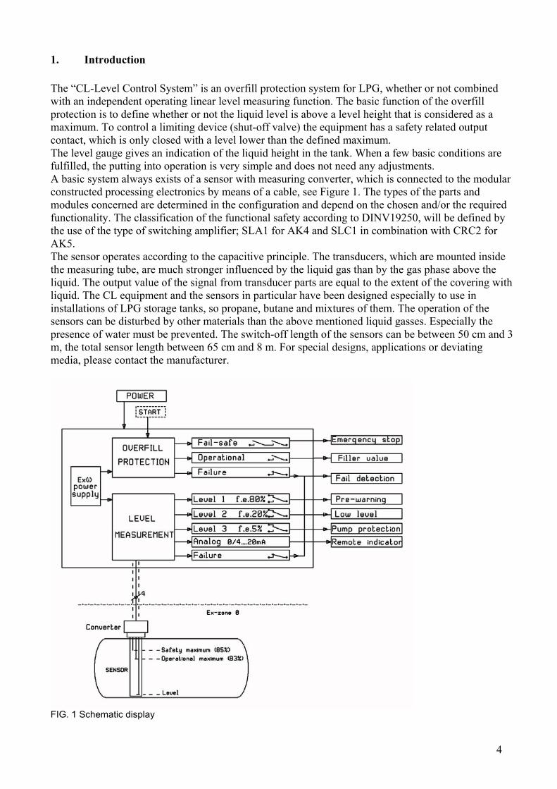
1. Introduction The “CL-Level Control System” is an overfill protection system for LPG, whether or not combined with an independent operating linear level measuring function. The basic function of the overfill protection is to define whether or not the liquid level is above a level height that is considered as a maximum. To control a limiting device (shut-off valve) the equipment has a safety related output contact, which is only closed with a level lower than the defined maximum. The level gauge gives an indication of the liquid height in the tank. When a few basic conditions are fulfilled, the putting into operation is very simple and does not need any adjustments. A basic system always exists of a sensor with measuring converter, which is connected to the modular constructed processing electronics by means of a cable, see Figure 1. The types of the parts and modules concerned are determined in the configuration and depend on the chosen and/or the required functionality. The classification of the functional safety according to DINV19250, will be defined by the use of the type of switching amplifier; SLA1 for AK4 and SLC1 in combination with CRC2 for AK5. The sensor operates according to the capacitive principle. The transducers, which are mounted inside the measuring tube, are much stronger influenced by the liquid gas than by the gas phase above the liquid. The output value of the signal from transducer parts are equal to the extent of the covering with liquid. The CL equipment and the sensors in particular have been designed especially to use in installations of LPG storage tanks, so propane, butane and mixtures of them. The operation of the sensors can be disturbed by other materials than the above mentioned liquid gasses. Especially the presence of water must be prevented. The switch-off length of the sensors can be between 50 cm and 3 m, the total sensor length between 65 cm and 8 m. For special designs, applications or deviating media, please contact the manufacturer.
FIG. 1 Schematic display

5
2. Description and operation
2.1 Sensor A sensor consists of a tube assembled to the connecting flange in which the actual transducers (capacitive sensor tubes) are being included. The sensors are available in two basic models:
• Only maximum level detection or overfill protection (CL-SRO) or • A combination with linear level measurement (CL-SRON)
Figure 2 shows an example of a sensor of the second type. The type CL-SRO has three connections, the CL-SRON four. Every connection is a separate capacitive sensor tube. The connections are encoded in size as well as in colour. It is not allowed to change these codes. Colour Tab size Abbreviation Meaning Function
White 2,8mm Cr Reference
Red 6,3mm Cu Limiting
Blue 4,8mm Cs Simulation
Overfill protection
Green 2,8mm Cn Level Linear level measurement
Table 1. Sensor connections
FIG. 2. Sensor type CL-SRON (DN50)

6
The transducers for the overfill protection and the one for level measurement do not influence each other and operate independent. The sensor always has to be in a more or less vertical position, the angle must deviate 45º as a maximum. The sensor and the metal parts in the tank are completely made of stainless steel. The plastics applied are high-quality polymers or resins, LPG and most of the liquid hydrocarbons resistant. There are three standard flange models: DN40, DN50 and SR. Other process connections can be realised by an adapter flange. The sensors are being made according to the specifications of the client. For this purpose a sensor data sheet has been made, which the client has to fill in and return signed. The sensor will be made in accordance with this sheet and after that changes are no longer possible. The pre-warning (or operational level) and switch-off point and the measuring range are fixed in the sensor construction. The level-measuring sensor ranges from approximately 6% of the diameter of the tank from the bottom till just passed the switch-off point. The pre-warning or operational level bar (RELEASE) lies approximately 2% below the real safety related switch-off point (AB) of the overfill protection. Please contact the manufacturer for special models or questions. By means of the measuring converter, the operation of the sensor is being amplified in the next paragraph (2.2).
2.2 Measuring converter The measuring converter consists of a solid grey lacquered aluminium housing in which the electronic circuits are cast in completely. The sensor connections are being fed in at the bottom and connected by means of tab connectors. When installed on the sensor, the housing is splashes and rainwater proof. Because of the open construction at the bottom there is sufficient ventilation and a difference of pressure cannot appear. Like that it is prevented that humidity can penetrate the housing and excessive development of condensation could take place. Just like the sensor the measuring converter can also be produced with or without level measurement. Furthermore the converter is not bound to the sensor or the length and does not need to be adjusted. The three transducers, like shown in table 1, take care of the creation of the frequency modulated current loop overfill protection signal. The value of the reference, limiting and simulation capacitance bear a certain proportion to each other. The signal changes under the influence of the medium in the sensor. In case of a critical mistake or failure, a switch-off follows (AB and RELEASE) in combination with a failure message (FAIL). The operation of the fail-safe circuit is based on a so-called dynamic fully hardware operated switching and failure detection. The signal consists of two quickly alternating levels, the basic level and a level, which is in accordance with the exceeding of the switch-off bar of the sensor concerned. Characteristic is the solid switching behaviour and, in case of a failure situation, the very fast responding detection in tenth of a second. Wherever applicable, the size of the level measuring capacitance will be converted to a frequency modulated current loop signal for the level signal. The creation and processing of this signal is relatively trustworthy but furthermore not to be classified as fail-safe.
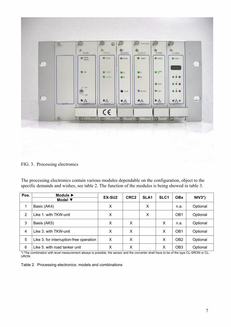
2.3 Processing electronics The processing electronics consist of a combination of so-called open euro-card modules. These modules have been placed in a rack, construction group carrier or complete wall housing. Besides that the modules can be placed in every other suitable housing like a 19-inch rack, provided that it meats IP20. Figure 3 shows an example of a detailed configuration with CL-SLC1 and CL-NIV3.
7
FIG. 3. Processing electronics The processing electronics contain various modules dependable on the configuration, object to the specific demands and wishes, see table 2. The function of the modules is being showed in table 3.
Module Pos. Model EX-SU2 CRC2 SLA1 SLC1 OBx NIV3*)
1 Basic (AK4) X X n.a. Optional
2 Like 1. with TKW-unit X X OB1 Optional
3 Basis (AK5) X X X n.a. Optional
4 Like 3. with TKW-unit X X X OB1 Optional
5 Like 3. for interruption-free operation X X X OB2 Optional
6 Like 5. with road tanker unit X X X OB3 Optional *) The combination with level measurement always is possible, the sensor and the converter shall have to be of the type CL-SRON or CL-URON. Table 2. Processing electronics: models and combinations

8
Pos. Type Function / description Remarks
1 CL-SU 230Vac/24Vdc mains power supply Optional, if no 24Vdc available
2 EX-SU2 Two-channel [EEx ia]-supply Intrinsic safe supply for the measuring circuits
3 CL-CRC2 Relay monitoring on behalf of CL-SLC1, for time limited or continuous operation
For AK5, only in combination with CL-SLC1 (pos.5)
4 CL-SLA1 Switching amplifier with redundant safety contacts (AB) and operational (pre) switch-off (RELEASE)
Overfill protection for AK4, with independent test buttons for both AB-contacts
5 CL-SLC1 Switching amplifier with redundant self-checking safety contacts (AB) and operational (pre) switch-off (RELEASE)
Overfill protection for AK5, always in combination with CL-CRC2 (pos.3)
6 CL-OB1
Road tanker interface with galvanic separation for [EEx i]-circuit and delayed for operational switch-off contact (VALVE), as replacement for RELEASE
Interface according to VdTÜV Merkblatt 100, overfill protection for LP Gas
7 CL-OB2 Bridging module for the safety contact AB For combination of CL-SLC1 and CL-CRC2 in interruption-free continuous operation
8 CL-OB3 Road tanker interface and bridging module Composition of modules CL-OB1 and OB2
9 CL-NIV3 Level reading with 3 free adjustable switching contacts
With auto-calibration and 0/4-20mA output.
Table 3. Overview of the modules The connections between the modules could have been made by a special connecting printed circuit board (PCB) or back plane, for example CL-BPL2, or by means of loose wiring. The use of the (complete) CL-BPL2 will keep the configuration of the processing electronics flexible and offers the possibility to change the equipment to new demands, circumstances or wishes in a simple way. Detached wiring or a back plane with limited connection possibilities will lay down the configuration more or less. After classification (according to DINV19250) of the safety function a difference is made between the two models for the overfill protection: the CL-SLA1 for AK4 and the CL-SLC1 and CRC2-combination for AK5. The CL-SLC1 is the highest classified and the most safety offering configuration. This one is also the most flexible in operating modes but is also a bit more complicated than the basic variant with CL-SLA1 for AK4. The two AB output contacts connected in series of the SLC1-unit are automatically being monitored by the CRC2-module. Like shown in table 4, three operating modes can be distinguished, the fourth is meant for test purposes only. With the remarks in this overview it is presumed that the switch-off point will not be exceeded. However, should the actual level be higher than the switch-off point at the moment that the relay-monitoring unit CL-CRC2 is executing the self-test, a definite switch off will follow and afterwards a restart must be executed.

9
No. Operating mode Time Jumper-settings Remarks
1 Time limited (Timed = T)
2½ hours (S) of 8¼ hours (L)
JP6 and JP7: T JP4 and JP5: S or L JP2 and JP3: not
Activation before each filling of the tank (START-button)
2 Interrupted continuous (Continuous = C) 2½ hours (S)
JP6 and JP7: C JP4 and JP5: S JP2 and JP3: not
- Continuous monitoring - Starting up once only (START) - AB and FAIL are being interrupted periodically
3
Interruption-free continuous (Continuous = C), only in combination with CL-OB2 of OB3
2½ hour (S) JP6 and JP7: C JP4 and JP5: S JP2 and JP3: not
- Continuous monitoring - Starting up once only (START) - AB stays closed - FAIL-contact opens periodically with every self-test
4 Indicative quick-test 1½ minute JP4 and JP5: S JP2 and JP3: yes For test purposes only
Table 4. Operating modes of CL-CRC2 and CL-SLC1 The model CL-SLA1 does not provide automatic relay contact monitoring. Both the relay contacts of the overfill protection (AB) must be tested twice a year with the test-buttons A and B to verify their switch-off ability. The possibility that, in case they should switch off, both relay contacts would stick in the same position at the same time, will be excluded in this way. The fail-safe AB-contact is always active and does not need to be activated internal or external. A separate time switch or relay must be added for a time limited operation. The level display CL-NIV3 indicates the liquid level. The actual measurement is a height measurement, however, this module standard will be set on the display in volume percentages of a horizontal cylinder tank, if applicable. A sine sign will appear in the right upper corner of the display, this sign is missing in the linear mode. The module CL-NIV3 based on a micro-controller disposes of three free adjustable switching contacts and besides that a 0/4-20mA output signal, right in proportion with the level indicated on the CL-NIV3 module a quadruple DIP-switch is situated, of which the setting possibilities for amongst others the level representation (pos.3) and the 0 or 4 to 20mA-output signal (pos.2) are shown in table 5. DIP-switch Function ON OFF
1 Analogue offset, not applicable for CL 0..20mA / 0..1V / 0..5V 4..20mA / 0,2..1V / 1..5V
2 Output signal 0..20mA 0mA= 0%; 20mA = 100%
4..20mA 4mA = 0%; 20mA = 100%
3 Level display Compensated for a horizontal cylinder tank, with sine sign in display
Linear, without extra indicator in display
4 Test and calibration Fixed Only production mode
Table 5. DIP-switches of CL-NIV3
3. Safety The primary function of the CL-system is to protect LPG-tanks against overfilling. There always must be enough space above the liquid to intercept expansion of the tank contents with a raising temperature. Therefore the system offers a safety related, fail-safe output contact to control the filling
10
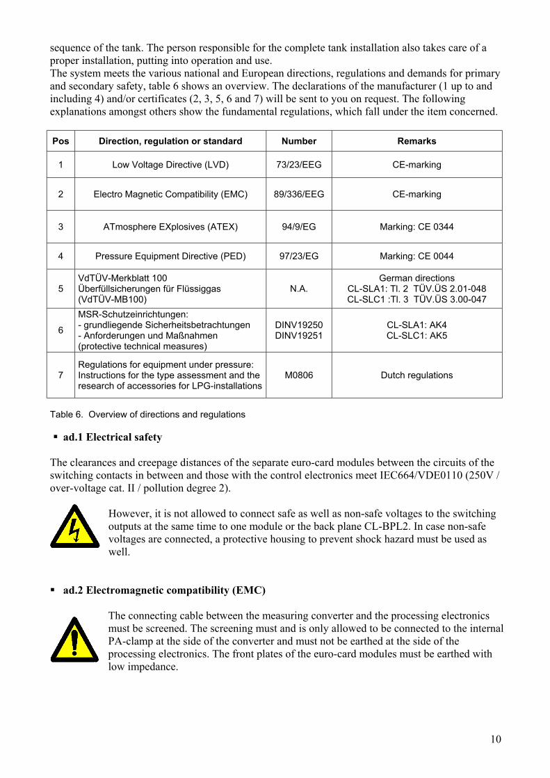
sequence of the tank. The person responsible for the complete tank installation also takes care of a proper installation, putting into operation and use. The system meets the various national and European directions, regulations and demands for primary and secondary safety, table 6 shows an overview. The declarations of the manufacturer (1 up to and including 4) and/or certificates (2, 3, 5, 6 and 7) will be sent to you on request. The following explanations amongst others show the fundamental regulations, which fall under the item concerned. Pos Direction, regulation or standard Number Remarks
1 Low Voltage Directive (LVD) 73/23/EEG CE-marking
2 Electro Magnetic Compatibility (EMC) 89/336/EEG CE-marking
3 ATmosphere EXplosives (ATEX) 94/9/EG Marking: CE 0344
4 Pressure Equipment Directive (PED) 97/23/EG Marking: CE 0044
5 VdTÜV-Merkblatt 100 Überfüllsicherungen für Flüssiggas (VdTÜV-MB100)
N.A. German directions
CL-SLA1: Tl. 2 TÜV.ÜS 2.01-048 CL-SLC1 :Tl. 3 TÜV.ÜS 3.00-047
6
MSR-Schutzeinrichtungen: - grundliegende Sicherheitsbetrachtungen - Anforderungen und Maßnahmen (protective technical measures)
DINV19250 DINV19251
CL-SLA1: AK4 CL-SLC1: AK5
7 Regulations for equipment under pressure: Instructions for the type assessment and the research of accessories for LPG-installations
M0806 Dutch regulations
Table 6. Overview of directions and regulations ad.1 Electrical safety
The clearances and creepage distances of the separate euro-card modules between the circuits of the switching contacts in between and those with the control electronics meet IEC664/VDE0110 (250V / over-voltage cat. II / pollution degree 2).
However, it is not allowed to connect safe as well as non-safe voltages to the switching outputs at the same time to one module or the back plane CL-BPL2. In case non-safe voltages are connected, a protective housing to prevent shock hazard must be used as well.
ad.2 Electromagnetic compatibility (EMC)
The connecting cable between the measuring converter and the processing electronics must be screened. The screening must and is only allowed to be connected to the internal PA-clamp at the side of the converter and must not be earthed at the side of the processing electronics. The front plates of the euro-card modules must be earthed with low impedance.
11
ad.3 Explosion safety The CL-system consists of explosion safe measuring circuits as a result of which the sensor with accompanying measuring converter is suitable for the use in storage tanks for fuels or other inflammable materials. Because of the highest level of protection an effective safety has been created for zone 0 for materials up to and including temperature group T4. The processing electronics must be installed outside the dangerous area. The ambient temperature for the parts in the dangerous area is from -40ºC to +70ºC. For the processing electronics this is from -25ºC to +60ºC. For completeness a module (CL-OB1 / OB3) is available, which disposes of an intrinsic safe tank truck interface (according to VdTÜV-Merkblatt Überfüllsicherung 100).
If not already delivered as such, the processing electronics must be placed in a housing so they at least meet IP20 (according to IEC529). Especially in case the modules are not yet wired in advance, for example by a connecting backplane like CL-BPL2 or a completely installed wall housing, the installation must take place in a way that the wiring inside and outside will meet the requirements of EN50020, par. 6.3.1 and 6.3.2. To meet the requirements of separation the PE- or earth clamp(s) of the connecting CL-BPL2, or of the switching amplifier modules CL-SLA1 or CL-SLC1, and/or other provisions installed for this reason has/have to be connected with safety earth. For the sake of potential levelling the measuring converter is provided with a PA-connection.
All the modules of the processing electronics have their own characteristic pin-utilization of the connector. Code pins in the counter connectors prevent the interchange with other modules. Because the sensors can be regarded as so-called “simple apparatus”, for this no special certification is needed. All CL-sensors delivered by CMT can and are allowed to be connected to the measuring converters type CL-URO(N) without any problem. In special cases and/or for further details, please see the data at the certificate. With regard to explosion safety the following markings are being put on the type plates of the modules concerned (as a minimum): CE-marking with the identification number of the notified body (0344, KEMA) The ‘Epsilon x’-sign in a hexagon Group of equipments, category and gas indication: II 1 G or II (1) G Way of protection, gas group and temperature classification: EEx ia IIB/C T4 or [EEx ia]
IIB/C Certificate number: KEMA 03ATEX1029X
In case the equipment or a part of it is damaged or otherwise if a situation arises, which could endanger the safety, the equipment must be shut off immediately.
ad.4. Pressure equipment
Because the overfill protection can be regarded as “safety accessory”, it falls under category IV, according to appendix II. The combination of the modules B (EC-type investigation) and D
12
(production quality control) is chosen in favour of the procedure of the assessment of conformity. The sensor bears the CE-marking, mentioning the number of the notified body responsible for module D: CE0044 The relevant applicable limiting value(s) for the sensor is/are: working pressure: PN40 temperature: -25ºC tot +50ºC
The installer is responsible for the installation of the sensor with sealing, connecting materials and equipment suitable for the flange and the application. When building in the sensor special attention has to be paid to the correct switch-off length. For each sensor this will be defined separately and confirmed by the customer. During the fabrication the switch-off length will be embossed in the sensor flange and mentioned on the sensor
certificate. ad 5. German TÜV-Bauartprüfung (type approval)
In the scope of the national German regulations the system has been approved for the application as overfill protection for LPG-storage tanks according to VdTÜV-Merkblatt 100, Überfüllsicherungen, “Richtlinie für die Bauteilprüfung von Überfüllsicherungen für Druckbehälter zur Lagerung von Flüs-siggas, Bau und Prüfgrundsätze” (edition 09.95). For the combination with CL-SLA1 according to part 2 and for CL-SLC1 with CL-CRC2 according to part 3. The difference is amongst others based on tank volume, the collecting phase of the medium and the presence of a safety valve or over pressure security. The constructions of the sensor and of the measuring converter are identical. “Operational swicht-off” and “road tanker interface” are concepts of the VdTÜV-Merkblatt 100. In case further information is desired about this, the best thing to do is to contact CMT. ad 6. Safety categories
As part of the regulations mentioned under 5., a corresponding difference has been made in safety categories according to DINV19250/1. ad 7. The Netherlands
For the application in Dutch LPG-tank installations the equipment must be judged on suitability for the application. Page M0806 is a list with all permitted accessories and equipment for propane, butane and LPG-tanks. Pay attention to the description what the equipment is meant for!
4. Packaging, transport and storage The sensors are being packed in a triangular, solid cardboard packaging . An extra wooden support will be placed as of approximately 4,5 m. The sensor will be packed in a wooden formwork, when very big lengths as of approximately 6 m are concerned. Nevertheless the sensor must be checked on (severe) damages and/or declination after each transport. In the factory the flange head is provided with a flexible plastic cover, which should only be removed when the converter is being installed, to protect the connecting wires. In special cases the converter could be assembled already. To avoid problems by (condensed) water when installing the sensor, it must be stored in a dry room. During storage the sensor must not get polluted, also watch out for loose pieces of packaging etc. The processing electronics and the modules are being installed in the rack of the housing in advance if applicable. The separation plane of the back plane CL-BPL2 in the rack must be extra protected. Loose euro-card modules must be transported in an ESD-protecting bag and a suitable packaging, which is not electrostatic chargeable. They must be stored in a clean and dry place. The modules should only be taken out of the packaging or the housing if precautions have been made against damages by ESD (Electro Static Discharge).
13
5. Assembling and installation
5.1 Safety
The installer has the responsibility for the use of the right sealing, connecting materials and leakage free installation. For this reason he must be qualified for the installation of, working at and handling LPG-installations. The installer must also be qualified for the installation of the electrical parts to guarantee a safe, reliable installation, which meets the applicable regulations. Especially the applicable regulations of explosion protection must be considered, amongst others:
Separate the intrinsic safe wiring from the non-safe wiring Mark the intrinsic safe wiring as such (light blue!).
5.2 Sensor Before installing the sensor the relevant sensor and tank data must be checked. The most important are: is the switch-off length of the tank concerned correct? Will the sensor be connected to the right flange connection? Furthermore the sensor must be checked on damages or other imperfections. Is the sensor already installed and once the tank is filled, an exchange will be much more difficult then.
5.3 Measuring converter For the connecting cable between processing electronics and measuring converter applies: Two or four cored (for CL-URO or CL-URON) Shielded Outer diameter: 5..10mm Core section: 0,25 … 1,5mm2 Maximum total resistance: 50Ω
The total assembling and installation procedure of the sensor and measuring converter can be summarized as follows:
• Check the sensor and the relevant data • Mount the sensor. Is the converter present, remove it first by unscrewing the four fixing
screws. • Remove the protecting cap of the sensor head, but never leave the sensor head unprotected, so
always an assembled converter or protecting cap. • Assemble the measuring converter:
- Remove the cover - Lead the three or four connecting wires from the bottom to the inside - Put the converter at the sensor head - Tighten the four fixing screws - Connect the three or four connecting wires of the sensor according to the (colour) coding - Lead the cable through the cable gland into the housing - Dismantle the connecting cable over a length of approximately 7 cm - Strip the connecting wires over a length of approximately 7 mm - Connect the wires of the connecting cable (make use of core end tubes !) - Cut the possibly not used wires - Connect the screen to one of the two free PA-terminals - For the sake of right sealing tighten the coupling nut of the cable gland - Mount the cover
14
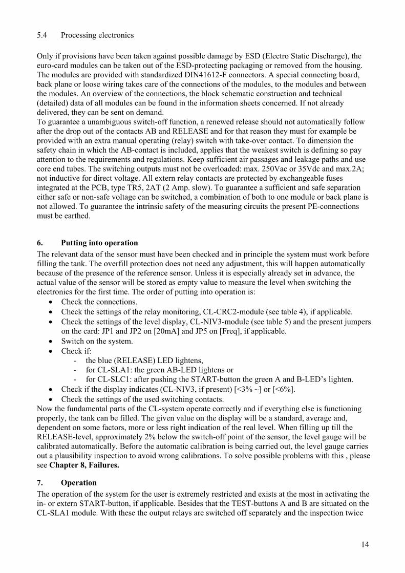
5.4 Processing electronics Only if provisions have been taken against possible damage by ESD (Electro Static Discharge), the euro-card modules can be taken out of the ESD-protecting packaging or removed from the housing. The modules are provided with standardized DIN41612-F connectors. A special connecting board, back plane or loose wiring takes care of the connections of the modules, to the modules and between the modules. An overview of the connections, the block schematic construction and technical (detailed) data of all modules can be found in the information sheets concerned. If not already delivered, they can be sent on demand. To guarantee a unambiguous switch-off function, a renewed release should not automatically follow after the drop out of the contacts AB and RELEASE and for that reason they must for example be provided with an extra manual operating (relay) switch with take-over contact. To dimension the safety chain in which the AB-contact is included, applies that the weakest switch is defining so pay attention to the requirements and regulations. Keep sufficient air passages and leakage paths and use core end tubes. The switching outputs must not be overloaded: max. 250Vac or 35Vdc and max.2A; not inductive for direct voltage. All extern relay contacts are protected by exchangeable fuses integrated at the PCB, type TR5, 2AT (2 Amp. slow). To guarantee a sufficient and safe separation either safe or non-safe voltage can be switched, a combination of both to one module or back plane is not allowed. To guarantee the intrinsic safety of the measuring circuits the present PE-connections must be earthed.
6. Putting into operation The relevant data of the sensor must have been checked and in principle the system must work before filling the tank. The overfill protection does not need any adjustment, this will happen automatically because of the presence of the reference sensor. Unless it is especially already set in advance, the actual value of the sensor will be stored as empty value to measure the level when switching the electronics for the first time. The order of putting into operation is:
• Check the connections. • Check the settings of the relay monitoring, CL-CRC2-module (see table 4), if applicable. • Check the settings of the level display, CL-NIV3-module (see table 5) and the present jumpers
on the card: JP1 and JP2 on [20mA] and JP5 on [Freq], if applicable. • Switch on the system. • Check if:
- the blue (RELEASE) LED lightens, - for CL-SLA1: the green AB-LED lightens or - for CL-SLC1: after pushing the START-button the green A and B-LED’s lighten.
• Check if the display indicates (CL-NIV3, if present) [<3% ~] or [<6%]. • Check the settings of the used switching contacts.
Now the fundamental parts of the CL-system operate correctly and if everything else is functioning properly, the tank can be filled. The given value on the display will be a standard, average and, dependent on some factors, more or less right indication of the real level. When filling up till the RELEASE-level, approximately 2% below the switch-off point of the sensor, the level gauge will be calibrated automatically. Before the automatic calibration is being carried out, the level gauge carries out a plausibility inspection to avoid wrong calibrations. To solve possible problems with this , please see Chapter 8, Failures.
7. Operation The operation of the system for the user is extremely restricted and exists at the most in activating the in- or extern START-button, if applicable. Besides that the TEST-buttons A and B are situated on the CL-SLA1 module. With these the output relays are switched off separately and the inspection twice

15
yearly is the primary goal. Besides that they are useful when inspecting those things, which are switched by the output concerned, for example the (emergency) stopping circuit and the valves. Furthermore the levels of the switching contacts can be changed by the push buttons 1, 2 and 3 on the CL-NIV3 module. The plan and construction is meant for a more or less single setting. The procedure is as follows:
• Carefully push the counter sunk button with an appropriate screwdriver during approximately 1 second until the level corresponding with this button appears in the display.
• Set the desired switching level with the adjacent, also countersunk potentiometer or adjusting screw. Turning to the right means increasing, turning to the left decreasing of the setting. If after 10 seconds the original level indication should return whereas the right value has not been reached, this procedure must be repeated.
By pressing the push buttons simultaneously the settings of the zero point and the calibration level can be changed. Besides that a manual calibration of the current level to the calibration level can be executed. See the instructions in the next chapter.
8. Failures Failures can be divided into two categories according to the nature of the failure and the solution of it; on the one hand in the first part of this chapter, broken parts or components, which have to be replaced and on the other hand in the second part, failures concerning the level gauge, which can be adjusted by manipulation of the settings. The failure indicators on the modules are a valuable help to solve the problems, which need to be exchanged. However, it is not always a fact that the module, which detects a failure, is also the cause. Below a number of possible situations are shown. In case a module or part is being disconnected or exchanged, the whole equipment must be made voltage-free.
8.1 Examples of failures Failure on EX-SU2 o Possible cause: a broken channel o Result: failures will be shown on the module(s), which depend(s) on the measuring circuit by the channel concerned, for example CL-SLA1 or CL-NIV3. o Solution: exchange of module EX-SU2 Failure on CL-SLA1 (or CL-SLC1) o Possible causes:
- Broken connection to measuring converter - Broken measuring converter - Sensor - Broken module
o Result: RELEASE and AB are off and the failure contact (FAIL) is active o Solutions:
- No voltage in the measuring converter: broken connection / break of a cable: repair - Sensor capacities, excl. Cu, are ok: broken measuring converter: exchange - Sensor capacities strongly deviating from the values set: sensor polluted or broken: exchange - Exchange of broken module
Failure repeats itself on CL-CRC2 o Possible cause: difference in channel setting or broken/deviation of a channel o Result: failure contact (FAIL) is active and AB-contact turns off o Solution: set both channels identical or exchange the module. Combination CL-SLC1 and CRC2: no failure report and yet AB and/or FAIL-contacts, which
interrupt themselves. o Possible causes:
- Module CL-OB2 is needed for interruption-free AB-function.
16
- The FAIL-contact will be interrupted briefly during each self-test, even with CL-OB2. o Solution:
- Install CL-OB2 module (or CL-OB3 if CL-OB1 is already present). - The FAIL-contact must not be combined or connected in series with AB. The FAIL contact is not fail-safe, but only indicates a fail-situation if this contact is active continuously.
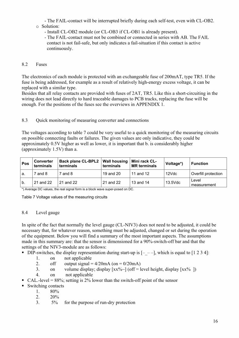
8.2 Fuses The electronics of each module is protected with an exchangeable fuse of 200mAT, type TR5. If the fuse is being addressed, for example as a result of relatively high-energy excess voltage, it can be replaced with a similar type. Besides that all relay contacts are provided with fuses of 2AT, TR5. Like this a short-circuiting in the wiring does not lead directly to hard traceable damages to PCB tracks, replacing the fuse will be enough. For the positions of the fuses see the overviews in APPENDIX 1.
8.3 Quick monitoring of measuring converter and connections The voltages according to table 7 could be very useful to a quick monitoring of the measuring circuits on possible connecting faults or failures. The given values are only indicative, they could be approximately 0.5V higher as well as lower, it is important that b. is considerably higher (approximately 1.5V) than a.
Pos Converter terminals
Back plane CL-BPL2 terminals
Wall housing terminals
Mini rack CL-MR terminals Voltage*) Function
a. 7 and 8 7 and 8 19 and 20 11 and 12 12Vdc Overfill protection
b. 21 and 22 21 and 22 21 and 22 13 and 14 13.5Vdc Level measurement
*) Average DC values, the real signal form is a block wave super-posed on DC. Table 7 Voltage values of the measuring circuits
8.4 Level gauge In spite of the fact that normally the level gauge (CL-NIV3) does not need to be adjusted, it could be necessary that, for whatever reason, something must be adjusted, changed or set during the operation of the equipment. Below you will find a summary of the most important aspects. The assumptions made in this summary are: that the sensor is dimensioned for a 90%-switch-off bar and that the settings of the NIV3-module are as follows: DIP-switches, the display representation during start-up is [–_– –], which is equal to [1 2 3 4]:
1. on not applicable 2. off output signal = 4/20mA (on = 0/20mA) 3. on volume display; display [xx%~] (off = level height, display [xx% ]) 4. on not applicable
CAL.-level = 88%; setting is 2% lower than the switch-off point of the sensor Switching contacts
1. 80% 2. 20% 3. 5% for the purpose of run-dry protection

17
Especially for the Dutch configurations the value of the sensor in empty condition is already stored in the memory of the CL-NIV3 module, which belongs to it as of that moment. The advantage is that although the tank is (partially) filled when putting into operation of the measuring system, it is possible to start with a correct empty setting. The display of the level could deviate extremely from the real contents during the first filling up, only after a successful auto-calibration one can speak of an accurate representation. The tank must at least be filled till the blue RELEASE-LED extinguishes as a result of which the auto-calibration takes place.
8.5 Display and auto-calibration The zero setting of the sensor value in empty condition will be stored in the memory of the CL-NIV3-module, and will only change when it is forcedly modified by manipulation with the help of push buttons (2 and 3). The exact switching behaviour of the overfill protection sensor will be used for the full setting (span or range). The automatic self-calibration occurs at the moment the level in the tank reaches the so-called operational switching level, indicated on the module as RELEASE and the blue LED, normally set on 88% (volume). When the level in the tank is higher than the RELEASE level then the blue LED is off and a straight line appears on the display of the CL-NIV3 module: for example [89%-]. An automatic calibration can only be activated under the following specific conditions: The system must already have detected the RELEASE condition
at the moment of switching- on and the rise of the level must at least be 5% and the rise must not be more than 10% per minute and the activation must take place within approximately 2½ hour after filling the tank.
Besides this the (auto) calibration can also be executed without the above-mentioned conditions, just by shortly and simultaneously pushing the buttons 1 and 3, which will result in a display of the actual level at the CAL-level set-in, which is [88%~]. Furthermore it is also possible to re-store both the empty as well as the full references by shortly pushing the counter sunk push buttons. A sensor simulator and capacitance meter are necessary for this, CMT can inform you about the purchase of them. The procedures for the use are described in the following paragraphs.
8.6 Monitoring and setting It is possible to simulate the electric capacity of a sensor in an empty condition and at another random level. However, a simulator equipped with a digital capacitance meter is necessary for this. With the help of these instruments you can easily perform, monitor and verify all settings and functions. Storing an empty value
• Switch off the power supply. • Adjust the capacity simulator on Cn, this value is mentioned in the sensor certificate and is also
marked in the sensor flange. • Detach the green sensor wire in the measuring converter. • Connect the capacity simulator to the released terminal of the measuring converter. • Switch on the power supply • Push buttons 2 and 3 simultaneously: [<3%~] appears on the display. • As a routine check, increase the capacity value a little (for example 10pF) as a result of which
the value on the indicator must rise, when this is not the case, then the new value has not been copied and the procedure must be repeated all over again.
• Switch off the power supply. • Connect the original green sensor wire again. • Switch on the power supply; the display must indicate the correct level now.

18
Remark: earlier empty and full values, if any, will disappear at each renewed empty setting, from that moment on the basic graph will be followed until the moment a calibration takes place. Manual span-calibration, deviating from the standard setting
• Push buttons 1 and 2 simultaneously (FIG. 4): the CAL-level can be set on each desired value within 10 seconds with the use of the potentiometer next to the failure indicator (FIG. 5), push buttons again, if necessary.
• Wait until there is normal read out again and push buttons 1 and 3 simultaneously: then the level gauge is calibrated in accordance with the CAL-level set earlier.
• After finishing this do not forget to set the CAL-level back to its original value of 88%!!! (as point 1).
Summary of the button functions For the setting the buttons must only be pushed shortly and, if necessary, simultaneously, for example with two fitting screwdrivers, however, always be careful in performing this! After pushing the button(s) you have approximately 10 seconds left to perform the setting, after this the system will automatically return to the level indication. Repeat the procedure, if necessary. Storing/setting of the present value as an empty value 2 + 3 Adjusting the present level to CAL-level set earlier 1 + 3 Setting the CAL-level with potentiometer beside FAIL-indicator 1 + 2 Setting the switch-off bars 1, 2 or 3 1, 2 or 3
FIG. 4 Pushing 1 and 2 so the FIG. 5 Setting the CAL-level CAL-level can be set

19
8.7 The use of the capacity simulator and capacitance meter Always set the capacitance meter at zero before use. The parasitic capacity of the measuring
flexes must be compensated before use, in other words: a zero setting with connected measuring flexes.
The simulator (model deviates from fig. 6) with a direct three-digit setting is very easy to use: o The black or yellow/green wire is the so-called mass and must be connected to the package
or tank; the grey wire is the (shielded) output, which must be connected to the measuring converter.
o Setting the capacity value, keeping 50pF in mind, which must always be added to the set value, for example: if Cn = 270 pF, then you must set 220pF !
o The capacity is always at the direct disposal of the (grey) clamp. It is necessary to detach the sensor wire from the converter connection when checking the sensor values using the meter. The measured capacity can (slightly) deviate from the embossed values, depending on the circumstances.
FIG. 6. The use of the capacity simulator The simulator shown deviates from the directly adjustable three-digit model
Fig.7 directly adjustable three-digit capacity simulator.
20
9. Maintenance and cleaning The CL equipment does not need a lot of maintenance. The most important thing is that the sensor is being protected against water and pollutions, in any form and situation whatsoever. In case the sensor should catch any water, this must be removed as soon as possible and the sensor must be dried well outside the tank. Especially the inside must be free of possible moisture. In case of any doubt, please contact the manufacturer. Furthermore it is advisable to provide the screws of the measuring converter with some (copper) grease, so later on it can be unscrewed without any problems. The installed measuring converter is protected against splashes and rainwater, however, water could penetrate the converter from the bottom. In case the system fails because of water in the converter, the installation must be shut off immediately; the electric connections will be damaged because of electrolysis. The present water must be removed immediately and the converter must be dried well at the inside. The processing electronics do not need any further maintenance; the equipment must stay clean and dry.
10. Putting out of order, major repairs and revision In case the sensor, converter, processing electronics or parts of them are severely damaged or if the safety is not longer guaranteed because of other circumstances, the equipment must be put out of order immediately. Therefore, the equipment and connected parts must be voltage-free. To put back into operation the damaged or broken parts must be judged, replaced and/or repaired by qualified persons; in case of doubt, always contact the manufacturer. In case of re-inspection and pressure testing of the tank with water, the sensor must (temporarily) be removed. If this is not possible or not desired, this situation should exist as shortly as possible and the sensor must dry in a voltage-free condition outside the tank. Of course the equipment must be voltage-free in any case. Before replacing and renewed putting into operation, the sensor must be tested on well operating. If the sensor has been exposed to water, the guarantee expires.
11. Scrap Materials to be scrapped must be removed according to the (government) regulations, which apply at that moment. For the biggest part the sensor exists of stainless steel; only a few parts are made of plastic and the electric connections at the flange are founded with PU-resin. The converter and the modules of the processing electronics do not have any particular environmental damaging or dangerous parts, as far as known at this moment.
21
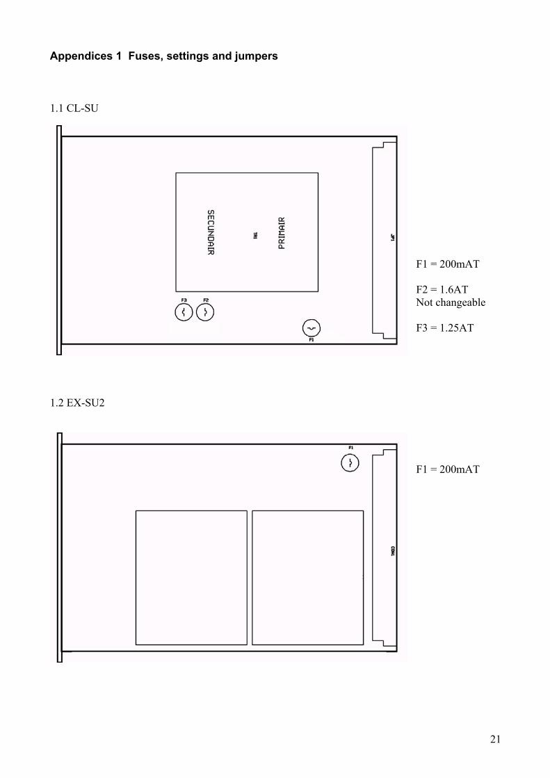
Appendices 1 Fuses, settings and jumpers
1.1 CL-SU F1 = 200mAT F2 = 1.6AT Not changeable F3 = 1.25AT
1.2 EX-SU2
F1 = 200mAT

22
1.3 CL-CRC2
F1 = 200mAT F2 = 2AT (K4, fail) JP1: contact type
No. Operating mode Time Jumper-settings Remarks
1 Time limited (Timed = T)
2½ hours (S) of 8¼ hours (L)
JP6 and JP7: T JP4 and JP5: S or L JP2 and JP3: not
Activation before each filling of the tank (START-button)
2 Interrupted continuous (Continuous = C) 2½ hours (S)
JP6 and JP7: C JP4 and JP5: S JP2 and JP3: not
- Continuous monitoring - Starting up once only (START) - AB and FAIL are being interrupted periodically
3
Interruption-free continuous (Continuous = C), only in combination with CL-OB2 of OB3
2½ hour (S) JP6 and JP7: C JP4 and JP5: S JP2 and JP3: not
- Continuous monitoring - Starting up once only (START) - AB stays closed - FAIL-contact opens periodically with every self-test
4 Indicative quick-test 1½ minute JP4 and JP5: S JP2 and JP3: yes For test purposes only
Table 4. Operating modes of CL-CRC2 and CL-SLC1 Remark: be aware that the setting of the jumpers for both channels are identical: JP4 corresponding with JP5 and JP6 with JP7.
23
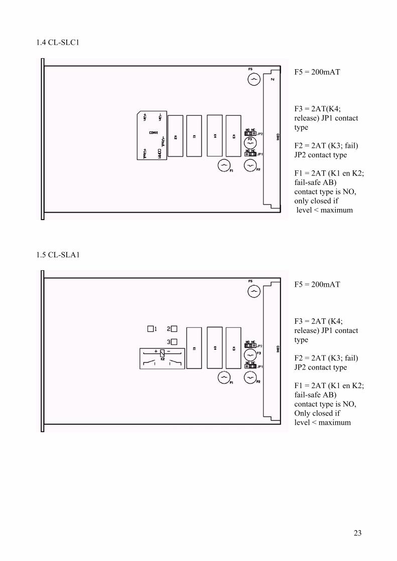
1.4 CL-SLC1
F5 = 200mAT F3 = 2AT(K4; release) JP1 contact type F2 = 2AT (K3; fail) JP2 contact type F1 = 2AT (K1 en K2; fail-safe AB) contact type is NO, only closed if level < maximum
1.5 CL-SLA1 F5 = 200mAT F3 = 2AT (K4; release) JP1 contact type F2 = 2AT (K3; fail) JP2 contact type F1 = 2AT (K1 en K2; fail-safe AB) contact type is NO, Only closed if level < maximum
24
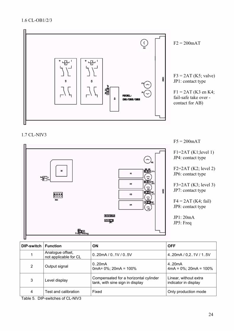
1.6 CL-OB1/2/3 F2 = 200mAT F3 = 2AT (K5; valve) JP1: contact type F1 = 2AT (K3 en K4; fail-safe take over -contact for AB)
1.7 CL-NIV3 F5 = 200mAT F1=2AT (K1;level 1) JP4: contact type F2=2AT (K2; level 2) JP6: contact type F3=2AT (K3; level 3) JP7: contact type F4 = 2AT (K4; fail) JP8: contact type JP1: 20mA JP5: Freq
DIP-switch Function ON OFF
1 Analogue offset, not applicable for CL 0..20mA / 0..1V / 0..5V 4..20mA / 0,2..1V / 1..5V
2 Output signal 0..20mA 0mA= 0%; 20mA = 100%
4..20mA 4mA = 0%; 20mA = 100%
3 Level display Compensated for a horizontal cylinder tank, with sine sign in display
Linear, without extra indicator in display
4 Test and calibration Fixed Only production mode Table 5. DIP-switches of CL-NIV3

25
Appendices 2 Conformation sheet for sensor dimensions
Overfill protection for LPG: Type “CL“
Company : ............................. Name : ............................... Order number : ............................. Location : ............................. Date : ...............................
A = …… mm C = …… mm B = …… mm D = …… mm Maximum level = …… % Overfill protection: Switch-off length D = A + B + wall thickness (+ eventual thickness adaptor flange) Level measuring sensor: Sensor length = A + 0.94 C (+eventual thickness adaptor flange) Remarks:
• The sensor will be dimensioned according to the safety related maximum level, the operational level is situated approx. 2% below this level.
• To be able to check the function of the overfill protection, the opening of the ullage has to be just above the maximum safety level.
• The probe for the level measurement reaches to approx. 0.06 C from the bottom. • Other tank types on request.
26
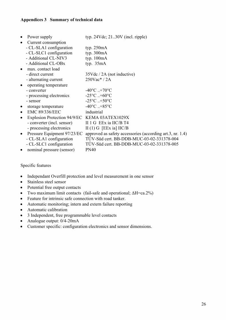
Appendices 3 Summary of technical data • Power supply typ. 24Vdc; 21..30V (incl. ripple) • Current consumption
- CL-SLA1 configuration typ. 250mA - CL-SLC1 configuration typ. 300mA - Additional CL-NIV3 typ. 100mA - Additional CL-OBx typ. 35mA
• max. contact load - direct current 35Vdc / 2A (not inductive) - alternating current 250Vac* / 2A • operating temperature - converter -40°C ..+70°C - processing electronics -25°C ..+60°C - sensor -25°C ..+50°C • storage temperature -40°C ..+85°C • EMC 89/336/EEC industrial • Explosion Protection 94/9/EC KEMA 03ATEX1029X - converter (incl. sensor) II 1 G EEx ia IIC/B T4 - processing electronics II (1) G [EEx ia] IIC/B • Pressure Equipment 97/23/EC approved as safety accessories (according art.3, nr. 1.4) - CL-SLA1 configuration TÜV-Süd cert. BB-DDB-MUC-03-02-331378-004 - CL-SLC1 configuration TÜV-Süd cert. BB-DDB-MUC-03-02-331378-005 • nominal pressure (sensor) PN40 Specific features • Independant Overfill protection and level measurement in one sensor • Stainless steel sensor • Potential free output contacts • Two maximum limit contacts (fail-safe and operational; ∆H=ca.2%) • Feature for intrinsic safe connection with road tanker. • Automatic monitoring; intern and extern failure reporting • Automatic calibration • 3 Independent, free programmable level contacts • Analogue output: 0/4-20mA • Customer specific: configuration electronics and sensor dimensions.
27
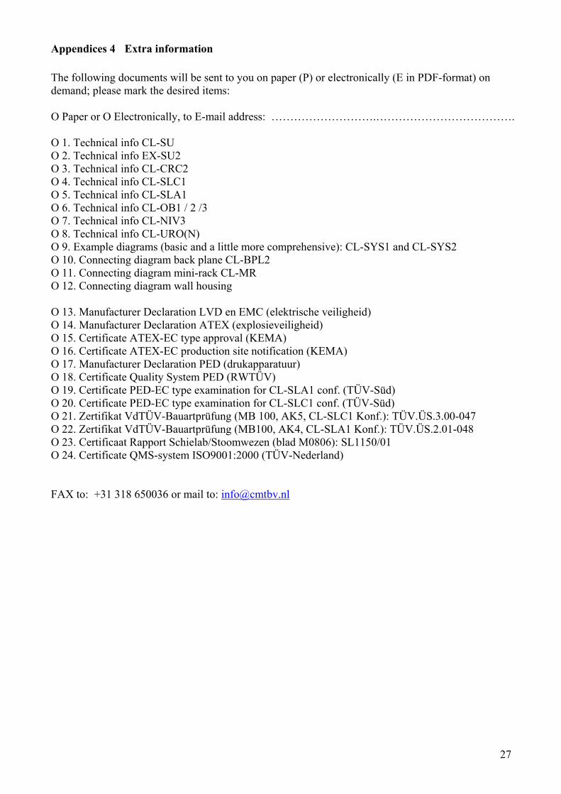
Appendices 4 Extra information The following documents will be sent to you on paper (P) or electronically (E in PDF-format) on demand; please mark the desired items: O Paper or O Electronically, to E-mail address: ……………………….………………………………. O 1. Technical info CL-SU O 2. Technical info EX-SU2 O 3. Technical info CL-CRC2 O 4. Technical info CL-SLC1 O 5. Technical info CL-SLA1 O 6. Technical info CL-OB1 / 2 /3 O 7. Technical info CL-NIV3 O 8. Technical info CL-URO(N) O 9. Example diagrams (basic and a little more comprehensive): CL-SYS1 and CL-SYS2 O 10. Connecting diagram back plane CL-BPL2 O 11. Connecting diagram mini-rack CL-MR O 12. Connecting diagram wall housing O 13. Manufacturer Declaration LVD en EMC (elektrische veiligheid) O 14. Manufacturer Declaration ATEX (explosieveiligheid) O 15. Certificate ATEX-EC type approval (KEMA) O 16. Certificate ATEX-EC production site notification (KEMA) O 17. Manufacturer Declaration PED (drukapparatuur) O 18. Certificate Quality System PED (RWTÜV) O 19. Certificate PED-EC type examination for CL-SLA1 conf. (TÜV-Süd) O 20. Certificate PED-EC type examination for CL-SLC1 conf. (TÜV-Süd) O 21. Zertifikat VdTÜV-Bauartprüfung (MB 100, AK5, CL-SLC1 Konf.): TÜV.ÜS.3.00-047 O 22. Zertifikat VdTÜV-Bauartprüfung (MB100, AK4, CL-SLA1 Konf.): TÜV.ÜS.2.01-048 O 23. Certificaat Rapport Schielab/Stoomwezen (blad M0806): SL1150/01 O 24. Certificate QMS-system ISO9001:2000 (TÜV-Nederland) FAX to: +31 318 650036 or mail to: [email protected]