Unsteady Flow Simulation of High-Lift stall Hysteresis ... · PDF fileof High-Lift stall...
46
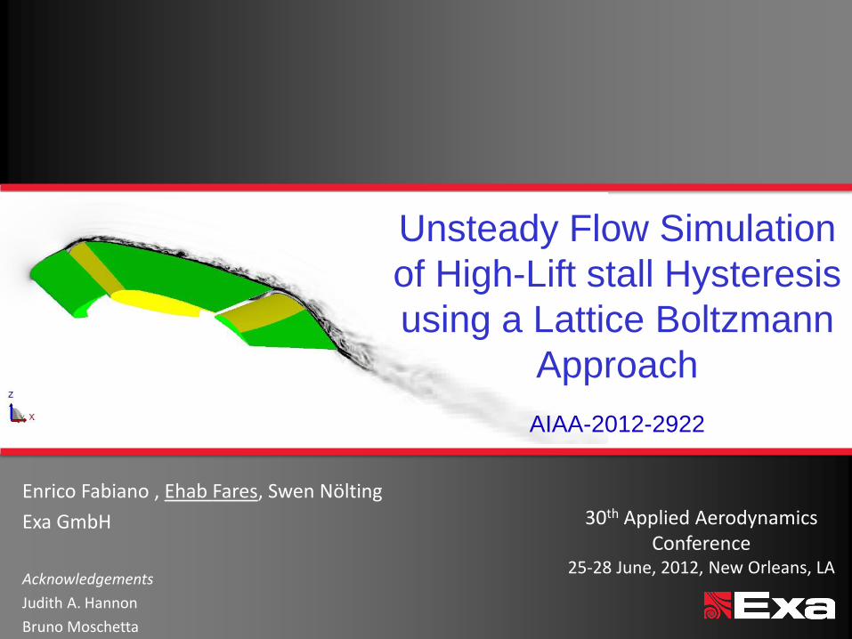
Enrico Fabiano , Ehab Fares, Swen Nölting Exa GmbH Acknowledgements Judith A. Hannon Bruno Moschetta Unsteady Flow Simulation of High-Lift stall Hysteresis using a Lattice Boltzmann Approach AIAA-2012-2922 30 th Applied Aerodynamics Conference 25-28 June, 2012, New Orleans, LA
Transcript of Unsteady Flow Simulation of High-Lift stall Hysteresis ... · PDF fileof High-Lift stall...
Enrico Fabiano , Ehab Fares, Swen Nölting
Exa GmbH
Acknowledgements
Judith A. Hannon
Bruno Moschetta
Unsteady Flow Simulation
of High-Lift stall Hysteresis
using a Lattice Boltzmann
Approach
AIAA-2012-2922
30th Applied Aerodynamics Conference
25-28 June, 2012, New Orleans, LA

© Exa Corporation 2
Overview
Introduction – TrapWing Geometry
Numerical Method – Lattice-Boltzmann based code (PowerFLOW)
Turbulence Modeling
Boundary Conditions
Results – 1st High-Lift Workshop / AIAA 2011 - 0869 results review – Simulation Overview – Sensitivity to laminar regions – Investigation of hysteresis effect
Coarse and fine simulation
Conclusions & Outlook
© Exa Corporation 3
Introduction
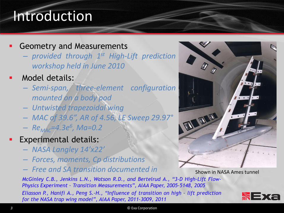
Geometry and Measurements – provided through 1st High-Lift prediction
workshop held in June 2010
Model details: – Semi-span, three-element configuration
mounted on a body pod – Untwisted trapezoidal wing – MAC of 39.6”, AR of 4.56, LE Sweep 29.97° – ReMAC=4.3e6, Ma=0.2
Experimental details: – NASA Langley 14’x22’ – Forces, moments, Cp distributions – Free and SA transition documented in
Shown in NASA Ames tunnel
McGinley C.B., Jenkins L.N., Watson R.D., and Bertelrud A., “3-D High-Lift Flow-
Physics Experiment – Transition Measurements”, AIAA Paper, 2005-5148, 2005
Eliasson P., Hanifi A., Peng S.-H., “Influence of transition on high – lift prediction
for the NASA trap wing model”, AIAA Paper, 2011-3009, 2011

© Exa Corporation 4
0
0.5
1
1.5
2
2.5
3
3.5
-5 0 5 10 15 20 25 30 35 40
CL
[-]
Experiment - Uncorrected forces- increasing Alpha
Experiment - Uncorrected forces- decreasing Alpha
Trap Wing in the NASA Langley WT
Introduction
Hysteresis effect discussed in the talk
Windtunnel Measurement ~30s per AoA ΔAoA ~0.5°-2°
(~20s rotating, 8s data acquisition & 2s data writing)
© Exa Corporation 5
Overview
Introduction – TrapWing Geometry
Numerical Method – Lattice-Boltzmann based code (PowerFLOW)
Turbulence Modeling
Boundary Conditions
Results – 1st High-Lift Workshop / AIAA 2011 - 0869 results review – Simulation Overview – Sensitivity to laminar regions – Investigation of hysteresis effect
Coarse and fine simulation
Conclusions & Outlook
© Exa Corporation 6
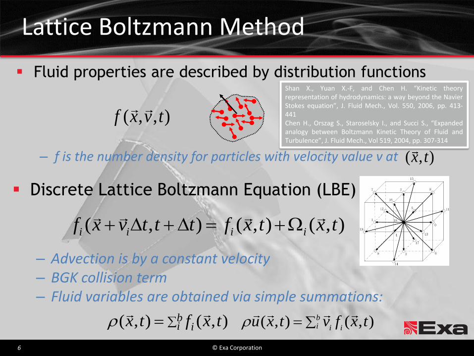
Lattice Boltzmann Method
Fluid properties are described by distribution functions
– f is the number density for particles with velocity value v at
( , , )f x v t
( , )x t
Discrete Lattice Boltzmann Equation (LBE)
– Advection is by a constant velocity – BGK collision term – Fluid variables are obtained via simple summations:
( , ) ( , ) ( , )i i i if x v t t t f x t x t
bi i txftx ),(),(
( , ) ( , )b
i i iu x t v f x t
Shan X., Yuan X.-F, and Chen H. “Kinetic theory representation of hydrodynamics: a way beyond the Navier Stokes equation”, J. Fluid Mech., Vol. 550, 2006, pp. 413-441 Chen H., Orszag S., Staroselsky I., and Succi S., “Expanded analogy between Boltzmann Kinetic Theory of Fluid and Turbulence”, J. Fluid Mech., Vol 519, 2004, pp. 307-314

© Exa Corporation 7
Turbulence Modeling
LBM – VLES Turbulence modeling approach – ‘Coherent’ statistically anisotropic eddies at larger scales
computed
– Statistically universal eddies in the inertial & dissipation ranges modeled
Boltzmann-τ model, uses a modified relaxation parameter
Extended RNG 2-equation model
– Swirl term used to switch between modeling & simulating eddies
Extended wall model – Rescale the thickness of the turbulent boundary layer
to account for pressure gradient effects Chen, H., Kandasamy, S., Orszag, S., Shock, R., Succi, S., and Yakhot, V., “Extended Boltzmann Kinetic Equation for Turbulent Flows,” Science, Vol. 301, 2003, pp. 633-636. Chen H., Teixeira C., and Molving K., “Realization of Fluid Boundary Condition via Discrete Boltzmann Dynamics”, Int. J. Mod. Phys. C, vol.9, pp.1281-1292, 1998.
© Exa Corporation 8
Overview
Introduction – TrapWing Geometry
Numerical Method – Lattice-Boltzmann based code (PowerFLOW)
Turbulence Modeling
Boundary Conditions
Results – 1st High-Lift Workshop / AIAA 2011 - 0869 – Simulation Overview – Sensitivity to laminar regions – Investigation of hysteresis effect
Coarse and fine simulation
Conclusions & Outlook
© Exa Corporation 9
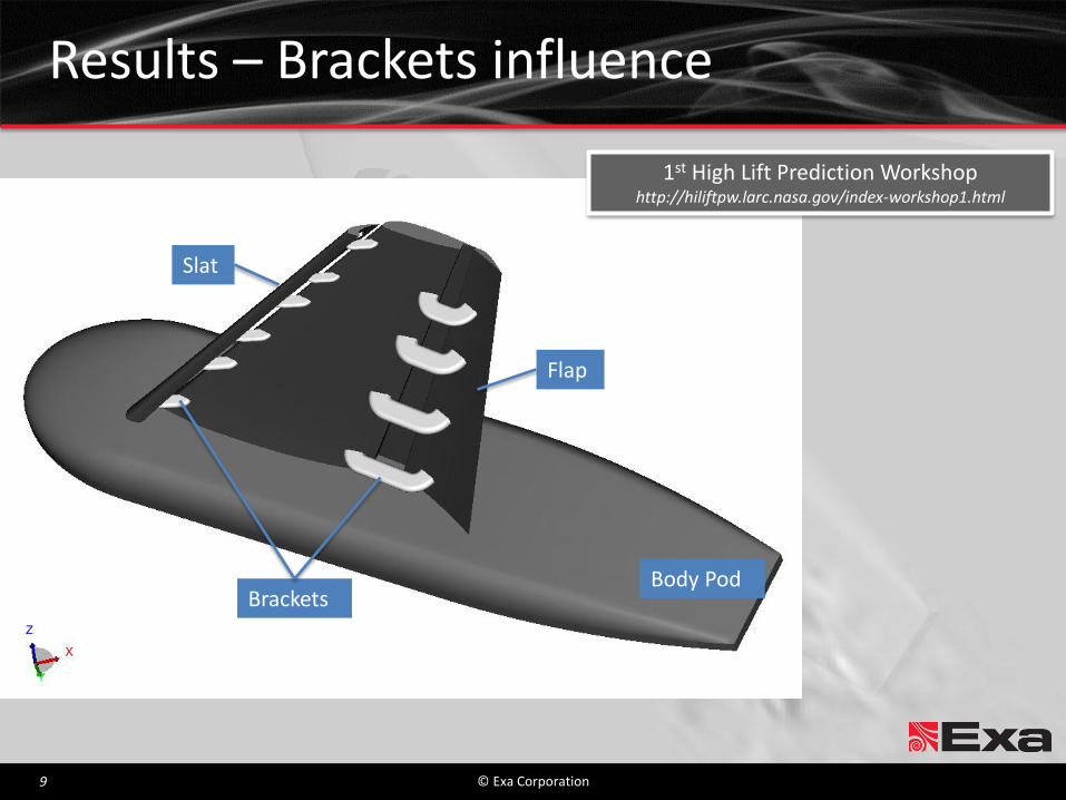
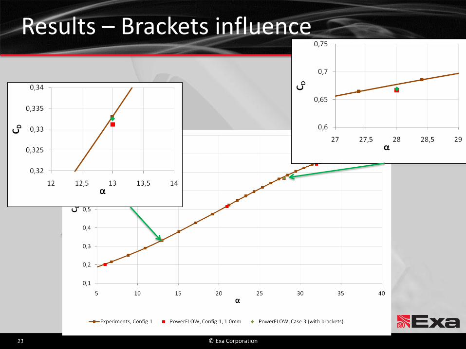
Results – Brackets influence
Flap
Brackets
Slat
Body Pod
1st High Lift Prediction Workshop http://hiliftpw.larc.nasa.gov/index-workshop1.html

© Exa Corporation 10
Results – Brackets influence
© Exa Corporation 11
Results – Brackets influence

© Exa Corporation 12
Slat Flap Main
α=13o, Config1, 95% span
α=28o, Config1, 41% span
Results – Brackets sensitivity
© Exa Corporation 13
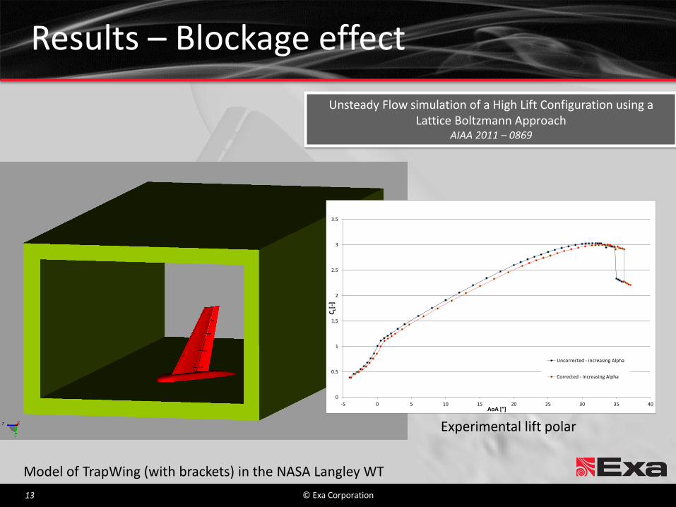
Model of TrapWing (with brackets) in the NASA Langley WT
Experimental lift polar
Results – Blockage effect
Unsteady Flow simulation of a High Lift Configuration using a Lattice Boltzmann Approach
AIAA 2011 – 0869
0
0.5
1
1.5
2
2.5
3
3.5
-5 0 5 10 15 20 25 30 35 40
CL[
-]
AoA [°]
Uncorrected - increasing Alpha
Corrected - increasing Alpha

© Exa Corporation 14
Results - Blockage Effects - Lift
0
0.5
1
1.5
2
2.5
3
3.5
-5 0 5 10 15 20 25 30 35 40
CL
[-]
Experiment - Uncorrected force
Experiment - Corrected forces
PowerFLOW - with WT wall
PowerFLOW - Free Air

© Exa Corporation 15
0
0.1
0.2
0.3
0.4
0.5
0.6
0.7
0.8
0.9
1
-5 0 5 10 15 20 25 30 35 40
CD
[-]
Experiment - Uncorrected forces
Experiemnt - Corrected forces
PowerFLOW - with WT wall
PowerFLOW - Free Air
Results - Blockage Effects - Drag

© Exa Corporation 16
-0.6
-0.5
-0.4
-0.3
-0.2
-0.1
0
-5 0 5 10 15 20 25 30 35 40
Cm
y[-
]
α [ ]
Experiment - Uncorrected Moments
Experiemnt - Corrected Moments
PowerFLOW - with WT wall
PowerFLOW - Free Air
Results - Blockage Effects - Pitching Moment

© Exa Corporation 17
Simulation Overview – Meshes
Setup 1 Setup 2
Setup1 Setup 2
Finest voxel size 1.25mm 1.25mm
Total number of Voxels 127 million 79 million
CPU-Hours 16,000 12,000

© Exa Corporation 18
Results – Sensitivity to laminar regions St
abili
ty a
nal
ysis
La
min
ar R
egi
on
s La
min
ar r
egi
on
s fr
om
Exp
eri
me
nt

© Exa Corporation 19
Results – Sensitivity to LR – Lift

© Exa Corporation 20
Results – Sensitivity to LR – AoA 36° h
1
7%
h
5
0%
h
9
5%

© Exa Corporation 21
Results – Sensitivity to LR – AoA 36°
LR from Experiment SA Laminar Regions
© Exa Corporation 22
0
0.5
1
1.5
2
2.5
3
3.5
-5 0 5 10 15 20 25 30 35 40
CL
[-]
Experiment - Uncorrected forces- increasing Alpha
Experiment - Uncorrected forces- decreasing Alpha
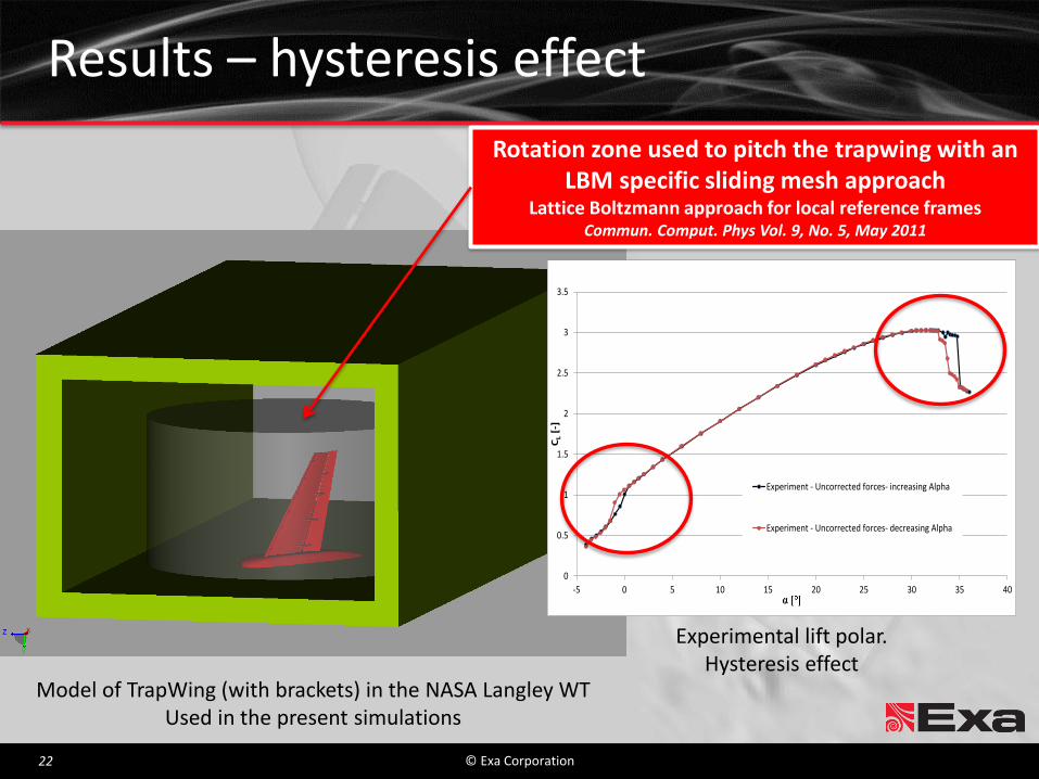
Model of TrapWing (with brackets) in the NASA Langley WT Used in the present simulations
Results – hysteresis effect
Experimental lift polar. Hysteresis effect
Rotation zone used to pitch the trapwing with an LBM specific sliding mesh approach
Lattice Boltzmann approach for local reference frames Commun. Comput. Phys Vol. 9, No. 5, May 2011

© Exa Corporation 23
Coarse case Fine case
Finest voxel size 1.875mm 1.25mm
Total number of Voxels 37 million 79 million
Total number of Surfels 5.4 million 9 million
Total number of Timesteps 1,454,700 3,313,660
Physical time 4.570s 5.280s
Covered AoA range 28° – 36° – 28° 32° – 36° – 32°
CPU-Hours 54,200 166,000
Results – hysteresis effect
© Exa Corporation 24
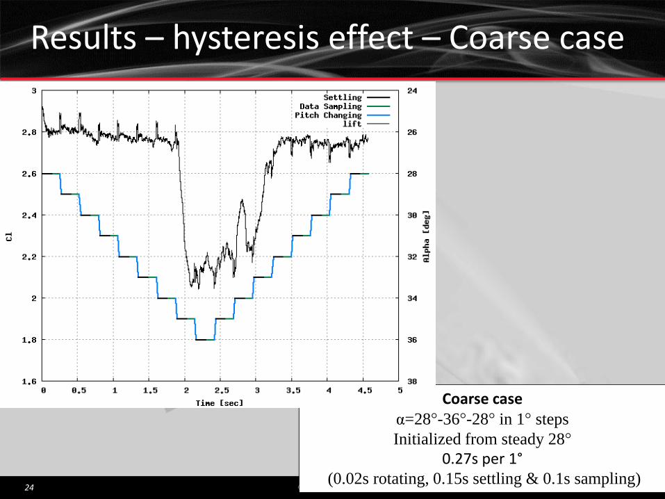
Coarse case α=28°-36°-28° in 1° steps
Initialized from steady 28°
0.27s per 1° (0.02s rotating, 0.15s settling & 0.1s sampling)
Results – hysteresis effect – Coarse case

© Exa Corporation 25
Results – hysteresis effect – Coarse case

© Exa Corporation 26
Results – hysteresis effect – Coarse case

© Exa Corporation 27
Results – hysteresis effect – Coarse case
Stall sequence

© Exa Corporation 28
Results – hysteresis effect – Coarse case
Stall sequence - AoA 33°

© Exa Corporation 29
Results – hysteresis effect – Coarse case
Stall sequence - AoA 34°

© Exa Corporation 30
Results – hysteresis effect – Coarse case
Stall sequence - AoA 35°
© Exa Corporation 31
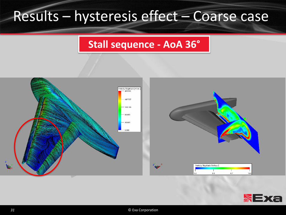
Results – hysteresis effect – Coarse case
Stall sequence - AoA 36°

© Exa Corporation 32
Results – hysteresis effect – Coarse case

© Exa Corporation 33
Results – hysteresis effect – Coarse case
AoA 32 Increasing AoA 32 Decreasing

© Exa Corporation 34
Results – hysteresis effect – Coarse case
AoA 33 Increasing AoA 33 Decreasing

© Exa Corporation 35
Results – hysteresis effect – Coarse case
AoA 34 Increasing AoA 34 Decreasing

© Exa Corporation 36
Fine case α=32°-36°-32° in 1° steps
Initialized from steady 32°
Variable settling time
Results – hysteresis effect – Fine case

© Exa Corporation 37
Results – hysteresis effect – Fine case

© Exa Corporation 38
Results – hysteresis effect – Fine case

© Exa Corporation 39
Results – hysteresis effect – Fine case

© Exa Corporation 40
Results – hysteresis effect – Fine case

© Exa Corporation 41
Results – hysteresis effect – Fine case
AoA 32 Increasing AoA 32 Decreasing

© Exa Corporation 42
Results – hysteresis effect – Fine case
AoA 33 Increasing AoA 33 Decreasing
© Exa Corporation 43
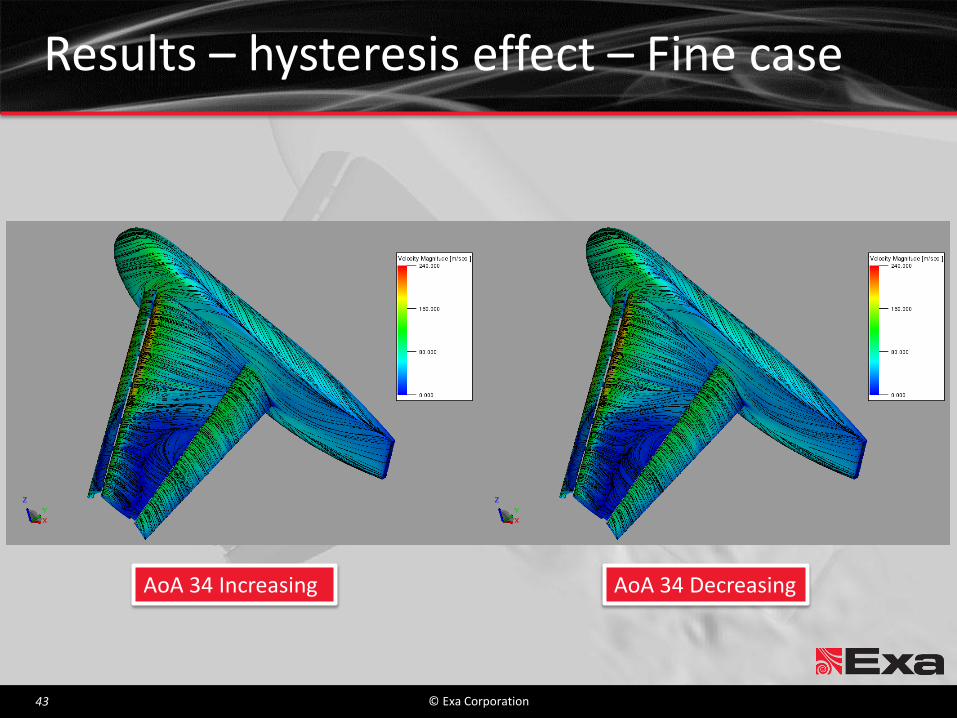
Results – hysteresis effect – Fine case
AoA 34 Increasing AoA 34 Decreasing

© Exa Corporation 44
Results – hysteresis effect – Fine case h
1
7%
h
5
0%
h
9
5%

© Exa Corporation 45
Overview
Introduction – TrapWing Geometry
Numerical Method – Lattice-Boltzmann based code (PowerFLOW)
Turbulence Modeling
Boundary Conditions
Results – 1st High-Lift Workshop / AIAA 2011 - 0869 results review – Simulation Overview – Sensitivity to laminar regions – Investigation of hysteresis effect
Coarse and fine simulation
Conclusions & Outlook

© Exa Corporation 46
Conclusions & Outlook
Unsteady Flow Simulations – Lattice Boltzmann Approach – Trap Wing with brackets in the NASA Langley WT
Hysteresis Study – Sensitivity to laminar regions for HiLift flows
Stall behavior
– Reasonable prediction of the hysteresis effect Underlying physical phenomena correctly captured Hysteresis predicted ~1°AoA compared to Experiment
Future studies will address – Larger settling time per AoA
Better agreement with exp. pitch – pause approach
– Other transition data? – Dynamic laminar regions modification