UNIVERSAL DYNAMICS, INC. - Extrusion Auxiliary UNIVERSAL DYNAMICS, INC. • 13600 Dabney Rd. •...
32
UNIVERSAL DYNAMICS, INC. S YSTEM E NGINEERING W ORLDWIDE DHD & PCT 2 Series DEHUMIDIFYING DRYERS 9/06
-
Upload
nguyenkhuong -
Category
Documents
-
view
222 -
download
1
Transcript of UNIVERSAL DYNAMICS, INC. - Extrusion Auxiliary UNIVERSAL DYNAMICS, INC. • 13600 Dabney Rd. •...

UNIVERSAL DYNAMICS, INC.S Y S T E M E N G I N E E R I N G W O R L D W I D E
DHD & PCT2 Series
DEHUMIDIFYING DRYERS
9/06

2 UNIVERSAL DYNAMICS, INC. • 13600 Dabney Rd. • Woodbridge, VA 22191
Page
Basic Principles of Drying ..............................................................................................4 - 5
Drying System Confi gurations ........................................................................................6 - 7
Twin Bed Desiccant Dryer Operation .................................................................................8
General Twin Bed Dryer Information ...................................................................................
DHD Series Dryer ..............................................................................................10
PCT2 Series Dryer ............................................................................................... 11
Feature Comparisons ............................................................................................................
DHD Series Dryer ..............................................................................................12
PCT2 Series Dryer ...............................................................................................13
Electric Dryer Feature Comparison - DHD & PCT2 ...........................................................14
Gas Dryer Feature Comparison - DHD & PCT2 ...............................................................15
Dryer Controls - DHD & PCT2 .......................................................................................16
Dryer Accessories - DHD & PCT2 .............................................................................17 - 18
Dryer Hoppers - General Information ...............................................................................20 TSC Drying Hopper ............................................................................................20 USC Drying Hopper ....................................................................................20 - 21 TSC Drying Hopper ............................................................................................21 Hopper Feature Comparison & Sizing .................................................................22 Hopper Options and Accessories .................................................................23 - 24
Table of Contents
Overview
Understanding the properties of plastic resins, as well as, why, when and how to dry them are the fi rst steps towards achieving the perfect end product. The fi rst three subtitles of this document are intended to of-fer an education into the characteristics of the plastics resin pellet, the basic elements of drying, what type of dryer is appropriate for a particular resin, the confi gurations available for a drying system and how the twin bed dehumidifying dryer operates. The remaining subtitles offer basic but thorough information for the DHD and PCT2 Series dehumidifying dryers, hoppers and any options available to enhance the system you choose.

3www.unadyn.com • [email protected]
Page
DataLogger .......................................................................................................................25
F.A.C.S. (Factory Acquisition Control System) ...................................................................26
Recommended Drying Conditions .............................................................................28 - 29
DHD Electric Dryer Specifi cations ....................................................................................30
DHD Gas Dryer Specifi cations .........................................................................................30
PCT2 Electric Dryer Specifi cations ....................................................................................31
PCT2 Gas Dryer Specifi cations ..........................................................................................31
Table of Contents - Continued
MCF = PPH x RTMBMATERIAL MB M
THROUGHPUT?BDBDLB
GHPGH
Formulate the best system for your application!

4 UNIVERSAL DYNAMICS, INC. • 13600 Dabney Rd. • Woodbridge, VA 22191
Basic Principles of Drying
Resin drying is a critical step in preparing the resin prior to being molded or extruded. Drying the resin suffi ciently before processing assures the quality of the end product. Generally the resin manufacturer will specify the resin drying time and maximum acceptable moisture level before it is processed. There are many different types of resin used in molding and extrusion. Regardless of type, for purposes of drying, all resins fall into one of two basic categories: Hygroscopic or Non-Hygroscopic. Hygroscopic resins retain moisture within the pellet. The amount of moisture plastic resin absorbs is determined by the chemical composition of the resin, the material’s temperature, and the amount of moisture the pellets are exposed to, pre-process. This results in different specifi ed drying times and moisture removal requirements for different types of resins. With Non-Hygroscopic resins the user only deals with surface moisture. The amount of mois-ture depends primarily upon the humidity and condensation. Both categories of resins need to be dried before being processed. Understanding and knowing the dif-ferent characteristics of the resin being used and providing the basic requirements of drying through proper equipment selection helps to ensure the quality of the end product and customer satisfaction.
Plastic Resin: Hygroscopic vs Non-Hygroscopic
Non-Hygroscopic Hygroscopic
• Moisture only on the surface of the pellet • Moisture is absorbed into the pellet
• Moisture easily removed by preheating • Moisture is not removed by preheating alone
• Generally, drying with hot air is suffi cient • Dehumidifying dryer is used for moisture for moisture removal removal
Example of Typical Non-Hygroscopic Resin Example of Typical Hygroscopic Resin
Natural Polyethylene, Polypropylene and PVC All engineered plastic resins1
Four Basic Elements of Drying:
Non-HygroscopicWater molecules must be
removed from the pellet surface.
HygroscopicA suffi cient amount of water molecules
must migrate to the surface of the pellet, in order to reduce the moisture to the
resin manufacturer specifi cations.
Heat Dry Air Airfl ow Exposure Time

5www.unadyn.com • [email protected]
Four Basic Elements of Drying - Continued
The basic elements that must be employed by a drying system to effectively reduce moisture content for processing are heat, dry air, airfl ow and exposure time. Heat is required for drying to raise the temperature of the air inside the drying hopper which increases the capacity of the dry air to take away water molecules.Dry Air, measured as dewpoint (typically -40 ºF), combined with heat, is delivered by Airfl ow. Airfl ow is measured in cubic feet per minute, or CFM, through a drying hopper. The hot dry air then carries the mois-ture away from the resin and out of the drying hopper. Residence Time, measured in hours, is the specifi ed amount of time the resin must be exposed to the hot, dry air to reach the required dryness for processing.
Hot Air Dryer or Desiccant Dryer?
Which type of dryer is best for your application? The fi rst step in deciding which is best is made by deter-mining the type of resin to be dried. Generally a Non-Hygroscopic resin requires a simple dryer using only heated ambient air. Operating as an open loop confi guration, the hot air from the dryer collects surface mois-ture from the pellets residing in the drying hopper. The hot air that fl ows through the hopper is released back into the atmosphere along with any moisture being extracted from the process material. The released hot air is never reintroduced back into the system. Hence the term “open loop”. Hygroscopic resins require “treated” air for moisture removal. For this application it is best to employ a de-humidifying dryer. These systems are generally a closed loop design using desiccant in conjunction with hot air to improve the drying effi ciency of the process air, absorbing water like a magnet. In a typical dehumidify-ing dryer there are two beds of desiccant, one that is collecting moisture from the process air and the other which is being regenerated in order to remove the collected moisture. Regeneration means that the moisture is removed from the desiccant so when the fi rst bed becomes saturated and the dewpoint degrades, the dryer can then switch to the regenerated desiccant bed. This will ensure the dryers ability to provide dehumidifi ed, low dewpoint air to the drying hopper at all times.
Dryer Size and Components
Now that you know what type of dryer to use there are other decisions you will need to make to complete your drying system. After identifying the specifi c drying requirements of the resin, you must choose an operat-ing confi guration that meets your needs and operational specifi cations. There are advantages as well as disad-vantages of each confi guration and the choices you make will have a direct impact on energy consumption, fl oor space utilization, material handling confi gurations, maintenance and much more. Whichever confi gura-tion you choose, it is important for you to understand the equipment, its capabilities and limitations as well as the optional components available, which may enhance the performance of your system. UnaDyn has created this dryer catalog to assist in the process of understanding the capabilities of the dryer and drying systems. Technical information and formulas are included to assist in sizing and selection. Our sales and technical support staff are always available to assist you with your selections to help assure that the decisions you make are economical and adequate for your current and future applications.
1 This includes non-hygroscopic material that has been compounded with hygroscopic agents like Carbon Black, minerals and fl ame retardants.

6 UNIVERSAL DYNAMICS, INC. • 13600 Dabney Rd. • Woodbridge, VA 22191
Dryer with Single Drying Hopper
Drying System Confi gurations:
Even a single dryer and hopper confi guration can be used as a central drying system when a single resin is used in more than one processing machine. Typically the dryer and hopper are fl oor mounted. The drying hopper is sized to accommodate the maximum resin usage and can be equipped with a multiple port vacuum take off device. The hopper may also be equipped with an adjustable high (fi ll) level sensor to reduce the hopper fi ll level in the event the system is not operating at its full rated processing capacity.
Dryer with Single Hopper for Central Drying
Dryer Floor Mounted, Hopper On or Over The Process Machine
The fl oor mounted dryer is located adjacent to the processing machine. Depending on size, the drying hopper may either be mounted directly to the throat of the machine, or if the hopper is too large, it may be mounted on a straddle support stand or mezzanine above the machine. In either case, the dried resin feeds directly into the throat of the machine.
To the Right: Floor Mounted Dryer, Hopper Mounted With Straddle Style Support Stand Above Processing Machine.
Dryer and Hopper Positioned Near the Machine
The dryer and the hopper are located adjacent to or in relatively close proximity to the processing machine. The hopper is mounted on a fl oor stand and equipped with a vacuum take off adaptor. The dried material is conveyed from the drying hopper to a receiver which is mounted either directly on the machine or to a material hopper on the machine.
To the Right: Dryer is Positioned Near the Machine and the Hopper is Mounted on a Stand. (Material is conveyed with either dry or ambient air depending on the resin specifi cations.)
Central Drying with Single Drying Hopper

7www.unadyn.com • [email protected]
Drying System Confi gurations - Continued
A multi hopper drying system utilizes a fl oor mounted dryer with the hoppers either mounted on a common support stand or on individual fl oor stands. The process air and return air fl ow to and from the hoppers are piped through a header system. The header system is equipped with butterfl y dampers, or half valves, to balance the air fl ow to each hopper. If more precise air fl ow distribution is needed, individual blower units may be used for each drying hopper. When multiple drying hopper systems are considered for drying multiple resins, each hopper is equipped with a process heater and an individual temperature controller.The individual hoppers are equipped with a vacuum take off assembly to accommodate the required number of take off ports. If each hopper is intended to supply dried resin to more than one process machine the hopper(s) can also be equipped with adjustable high (fi ll) level sensors to reduce the hopper fi ll level when not operating at its full rated capacity.
Central Drying with Multiple Drying Hoppers
Dryer with Two Hoppers A drying system with multiple hoppers is frequently designed to dry different resins in two or more drying hoppers at different drying tem-peratures simultaneously. The multi-hopper confi guration generally involves remote mounted heaters with individual controls for each dry-ing hopper. A dry air manifold delivers dry air to each drying hopper and each hopper has a diverter valve which permits the user to adjust or shut off the air fl ow to each hopper. Managing air fl ow to each drying hopper is critical to proper performance of this type of drying systems. If one or several of the hoppers are off line with low or no material, the diverter valves must be closed in order to avoid channeling dry air through empty hopper(s) at the expense of the remaining hopper(s) in the process loop. Each drying hopper has a vacuum take off with single or multi ports to permit conveying to individual or multiple machines, depending on operational requirements.
Above: Portable Confi guration - Single Dryer and Two Hoppers Mounted on a Single Stand.
Dryer with More Than Two Hoppers
Above (Top): Side View of Large DHD Dryer, Floor Mounted, for Central Drying Confi guration.Above (Bottom): Floor Mounted Dryer with Multiple Hoppers Equipped with Individual Process Heaters.
A less popular style of multiple hopper drying system involves the individual drying hoppers being mounted on or above the individual processing machines. The method of air distribution to the hoppers would be the same as the above confi guration, however, the routing of the duct work for these systems can be both complex, cumbersome and diffi cult to maintain a properly balanced process air fl ow.

8 UNIVERSAL DYNAMICS, INC. • 13600 Dabney Rd. • Woodbridge, VA 22191
Twin Bed Desiccant Dryer Operation: Standard Drying Operation Performance, reliability and simplicity are key design fea-tures of the UnaDyn solid bed dryer design. Solid desiccant beds develop uniform air fl ow which ensures the maximum contact between the moist air and the desiccant resulting in improved moisture removal, performance and effi ciency. Con-trolling the dryer cycle on dewpoint demand increases cycle time and substantially reduces regeneration energy usage. A continuous stream of dry air exits the “on line” desiccant tower, passes through the change over valve to the process air heater which raises it to the setpoint drying temperature prior to entering the drying hopper. The moisture laden air stream exits the drying hopper to the process air fi lter and blower. The air is then directed into the active desiccant bed where the moisture is absorbed from the process air loop.
High Temperature Drying Operation
The lower the temperature of the process air returning to the desiccant, the more effi ciently the desiccant will remove moisture. The maximum desirable operating return air temperature is 150ºF. Drying at elevated temperatures, typically greater than 250ºF, often results in return air temperatures in excess of 150ºF. If the return air temperature is expected to exceed 150ºF, a water cooled coil is recommended to be installed in the return air line between the fi lter and the dehumidifi er. This coil can be integral with the process air fi lter or freestanding depending on the size of the dryer. Additionally on drying applications requiring temperatures in excess of 250ºF we recommend high temperature hose, insulated drying hoppers and mounting the process air heater on the hopper.
Low Temperature Drying Operation When applying a dehumidifying dryer sys-tem on a low temperature drying application, typically 180°F or less, it is recommended that a cooling coil be included. This cooling coil is installed between the dehumidifi er and the drying hopper. Connection to a water source at 75ºF or less is required. When cool desic-cant absorbs moisture it generates heat which may exceed the process air set point. This coil is intended to protect the material being dried from exposure to process air which is at an elevated temperature.
Drying Hopper Regenerate On-Line
Cooling Coil
Remote HeaterRemote Heater
Simultaneously the desiccant in the second tower is being regenerated. Air is drawn into the regeneration air fi lter and blown to the heater which raises it to the regeneration temperature. The change over valve directs the air through the saturated desiccant bed driving off the moisture. The desiccant regeneration cycle includes three separate stages; Active heating, dynamic cooling and static cooling, all of which are phases of a complete regeneration bed cycle.
Cooling Coil

10 UNIVERSAL DYNAMICS, INC. • 13600 Dabney Rd. • Woodbridge, VA 22191
The DHD Series Dryer is a fully automatic high performance solid bed dehumidifi er featuring two molecular sieve desiccant beds. High Performance Change Over Valves and our exclusive valve tensions system ensure proper seating and reduced pressure loss across the system. Better air fl ow and positive sealing improve overall operation and effi ciency. De-signed for quick access and easy maintenance; sample, remove and fi ll the desiccant through the sample port. The DHD standard processing temperature range is 180° to 250° F. Optional heaters and cooling coils permit drying at temperatures below 180ºF or up to a maximum of 375°F. For drying temperatures higher than 250ºF with higher throughputs, gas dryers may be more cost effective.
Standard Features
• Gas or Electric Dryer • EASY Accessibility for Maintenance • High Performance Change Over Valves for Positive Sealing Bed Change Over and Effective High Temperature Iso- lation Between Regen and Process Air • Separate blowers for process and regeneration air. • High effi ciency fi lter systems - sight glass on process fi lter • Low Dewpoint -40ºF
• Up to 4500 CFM
Options
• Energy SavingEnergy Saving Desiccant Bed Insulation • Fused Disconnects • FN Controller w/ SPI Connect & Dewpoint Sensor • PLC w/Panel View Touchscreen Controls • Kahn Dewpoint Sensor • Data Logger
(Above) Interior view of Air Valves with silicon seal (red)
DHD-8
DHD Series Dryer
High Performance Precision Air Valves
Exclusive Valve Tensioning System
• Valves are “seated” to prevent leakage.• Seal is produced using a high-temp silicone that has excellent heat resistance.• Valve Tensioning System on valves prevent leakage.
Desiccant Sample/ Auto Fill and Removal Port • Easily check desiccant through sample port or use to remove and refi ll desiccant to its proper level automatically.

11www.unadyn.com • [email protected]
Reliable and optimally energy effi cient, the PCT2 Dryers are equipped with heavy duty change over valves that statically seal for a tight seal, experience minimal wear and never leak. The sleek cabinetized design is space saving, sound reducing and all operational and maintenance panels are located at one end of the machine for easy access. Pulse Cool-ing Technology (PCT2) produces tighter temperature and dewpoint controls which result in remarkably constant and stable dewpoint process temperatures throughout the drying cycle. Its closed loop design,
Standard Features
• Space Saving Cabinetized Components and Assemblies • Gas or Electric • Pulse Cooling Technology • Maintain Material Temperature at ±1ºF From Setpoint • Low Dewpoint (-60ºF) • FN Controller w/ SPI Connect & Dewpoint Sensor • Minimal Moving Parts • Side Panels remove for EASY Maintenance Accessibility • High Performance Change Over Valves • Insulated Desiccant Towers • Large Capacity Filter Element Optional Features • Fused Disconnects • PLC w/Panel View Touchscreen Controls • Kahn Dewpoint Sensor • Data Logger
PCT2 Dryer Series
Pulse Cooling Technology (PCT) Produces Tighter Temperature and Dewpoint Control
Time
UnaDyn PCT2 Dryer
Dew
poin
t
Drier
Wetter
Con
vent
iona
l R
otat
ing
Bed
Dry
er
Con
vent
iona
l Tw
in B
ed
Dry
er
insulated desiccant beds and material saver delivers more drying effi ciency per unit of power than any other comparable dryer on the market. Available in either Electric or Gas, the PCT2 delivers this enhanced performance while maintaining the simplicity of the twin tower design and minimal moving parts. The PCT2 dryer has a built-in cooling coil and is capable of processing resin at temperatures from 160ºF to 400ºF with a throughput range of 300lbs/hr to 4000lbs/hr.

12 UNIVERSAL DYNAMICS, INC. • 13600 Dabney Rd. • Woodbridge, VA 22191
FEATURE E - ELECTRIC
G - GAS
4 6 8 11 15 25 30 40 60 100 120
High Performance Air Valves E & G
Solid Desiccant Beds E & G
Desiccant Fill/Sample Ports E & G
Dual Blowers - Process & Regen E & G
Process Return Air Filter E & G
Filter View Glass E & G
Hose Pkg. - Dryer to Hopper E & G N/A N/A N/A N/A N/A
Tubular Heaters E
Digital Electronic Temp Control E N/A N/A N/A N/A N/A N/A
FNG Microprocessor w/ SPI Connect & Dewpoint Sensor G
FN or FNMH Microprocessor Control E
Remote FN or FNG Display E & G
AB-PLC Mono Chrome Display w/ SPI Connect & Dewpoint Sensor E & G
AB-PLC Maple Color Display w/ SPI Connect & Dewpoint Sensor E & G
High Temperature Package E & G
Low Temperature Package E
Cyclone Pre-Filter E & G
Plasticizer Filter/Cooler E & G
Alarm Bell or Light E & G
Kahn Dewpoint Sensor (Reads Below -40ºF)
E & G
Fused Disconnects E & G
External SPI Port (Requires Optional Controller)
E
DataLogger E & G
Insulated Desiccant Beds E & G
13x Desiccant E & G
Voltages other than 230 or 460 E
UL 508 Certifi ed Electric Panel E & G
Frame with Castors E & G N/A N/A N/A N/A N/A N/A N/A
Standard
Optional
DHD - ELECTRIC AND GAS MODEL FEATURE COMPARISON

13www.unadyn.com • [email protected]
FEATURE E - ELECTRIC
G - GAS
300 600 1000 1250 1500 2000 2500 3000
Cabinet Design w/ Removable Panels E & G
Pulse Cooling Technology E & G
High Performance Air Valves E & G
Solid Desiccant Beds E & G
13x Desiccant E & G
Dual Blowers - Process & Regen E & G
Process Return Air Filter E & G
High Temperature Package E & G
Tubular Heaters E
FN or FNG Microprocessor w/ SPI Connect & Dewpoint Sensor E & G
Remote FN or FNG Display E & G
AB-PLC Mono Chrome Display w/ Dewpoint Sensor E & G
AB-PLC Maple Color Display w/ Dewpoint Sensor E & G
Cyclone Pre-Filter E & G
Plasticizer Filter/Cooler E & G
Alarm Bell or Light E & G
DataLogger E & G
Kahn Dewpoint Sensor (Reads Below -40ºF) E & G
Voltages other than 460 E & G
UL 508 Certifi ed Electric Panel E & G
UL 508 Flame Safety Certifi ed G
PCT2 - ELECTRIC AND GAS FEATURE COMPARISON
Standard
Optional

14 UNIVERSAL DYNAMICS, INC. • 13600 Dabney Rd. • Woodbridge, VA 22191
The all electric designed DHD & PCT2 Dryers are avail-able in a full range of sizes. Reliability is built in with tubular heaters that have very low watt density that increases heater life. Multiple elements allow the heaters to operate even if an individual element has failed. Each element can be replaced separately and are easily accessed through single bolt clamps designed for simplifi ed maintenance. Double walled construction of the process heater offers safety and effi ciency. Cold air circulates around the heater core, preheating the air while cooling the outer surface of the heater housing. The heat which escapes is recovered and re-turned to the process air. Regeneration heaters are insulated with high temperature ceramic materials. Each DHD dryer is equipped with a standard digital elec-tronic temperature control. The PCT2 is equipped standard with an FN (Electric) or FNG (Gas) microprocessor control. Optional controls available are the FN microprocessor control for the DHD and an advanced PLC control on the DHD or the PCT2. All controllers display process setpoint and temper-ature and are simple to set up and operate. Optional con-trols display additional items such as dewpoint, alarms and a variety of other energy saving and processor friendly features. See our “Optional Controllers” section for details.
Electric Dryer System - DHD & PCT2
Optional Features
• HighHigh and and Low TemperatureLow Temperature applications for below 180ºF applications for below 180ºF to above 250º - 375ºF to above 250º - 375ºF • Fused Disconnects • Energy SavingEnergy Saving Desiccant Bed Insulation • FN Controller w/ SPI Connect & Dewpoint Sensor • PLC w/Panel View Touchscreen Controls • Kahn Dewpoint Sensor • Data Logger
Optional FN Microprocessor
Control
High Performance Change Over Valves
Optional Process Air Cooler
(Low Temp Application)
MachineMounted Air Filter
( Reduces Floor SpaceRequirements )
Sight Glassfor Visual Observationon Process Air Filter
Optional Insulated Desiccant
Bed Design
Optional FusedDisconnect
DHD-25
Standard Features • Digital Electronic Temperature Control • SPI Connect • Dewpoint Meter • Material Saver Function

15www.unadyn.com • [email protected]
Natural, clean and effi cient, all DHD and PCT2 Dryer models, except the DHD-4, are available in a gas fi red confi guration. DHD & PCT2 gas fi red dryers can be used with natural gas or propane which may help reduce energy costs. The gas fi red heating system for both process and regeneration use non-ceramic type burners. Ceramic burners may, over time, become brittle and have, on average, a shorter life span than non-ceramic burners. The regeneration heating system is directly gas fi red. The process air heating system uses an exclusive composite radiant burner harnessed in a heat exchanger. These highly effi cient burners generate extremely low emissions. The Gas Fired DHD and PCT2 dryer confi guration come standard with the FNG Microprocessor control-ler featuring SPI connect. PLC controls are available as an option on both dryer series. All controllers display setpoint, temperature, dewpoint, alarms and a variety of other energy saving and user friendly features.
Optional Features • Energy SavingEnergy Saving Desiccant Bed Insulation 2
• Fused Disconnects • PLC w/Panel View Touchscreen Control • Hard Ducting recommended for dryer models DHD-25 or larger • Data Logger
Standard Features • External Gas Pack 1
• FNG Controller • SPI Connect • Dewpoint Meter • Material Saver Function
GAS Dryer System - DHD & PCT2
1 PCT2 Model 300 has built-in Gas Pack 2 Desiccant Bed Insulation Standard on all PCT2 Models
(Top) Gas DHD Dryer(Above) Gas Pack Illustration of airfl ow.(Right) Gas PCT2 Dryer

16 UNIVERSAL DYNAMICS, INC. • 13600 Dabney Rd. • Woodbridge, VA 22191
DHD & PCT2 Controllers
The FN-MH display and keypad offers a 4 character, segment LED display with a LED alarm indicator.
FN-MH Microprocessor Controller: DHD (Electric)
Allen Bradley PLC Controller: DHD & PCT2 (Gas or Electric)
The Allen Bradley PLC Control features a black and white touch screen display (4.75” x 2.38”) with an easy to use program that guides the user through the entire drying system setup and operation.
This Standard Control of the electric DHD dryer is equipped with a Digital Electronic Temperature Control.
Digital Temperature Controller: DHD Standard (Electric Only)
Other functions include dual heater control, programmable alarms, SQC capability, password protection and system diagnostics.
FN & FNG Controller: DHD - Standard (Gas Only) & PCT2 Standard (Gas or Electric)
• Basic Function of On/Off• Temperature Control
• Control Regeneration by Dewpoint or Time• Seven Day Clock - Auto operation as one time only or on a repetitive basis• Material Saver function - protects material from overheating• SPI Communications Protocol Built-in
The FN is Standard on the PCT2 and the FNG is Standard on the DHD and PCT2 Gas Dryers. Each display operating temperature and dewpoint with a setpoint fl ash approximately every three minutes.
Standard Controls
Optional Controls
• Time based Regeneration • Extreme Temperature Fluctuation Protection.
• Over Temperature and Under Temperature Alarms• Service Mode allows controller options, such as display options for Fahrenheit or Celsius• “Hopper Low/Material Level” when hopper is equipped w/ sensor• Supports SPI Communication with optional communication card
• Graphic display of system conditions for alarms, blower and heater operation, valve changeover, hopper level and fi lter condition• Material Saver and Dewpoint Extend Modes• Operational Data available with processor’s communications port• Larger displays and color screen options also available.

17www.unadyn.com • [email protected]
Optional Accessories
During the drying process of certain types of resins, vaporized volatiles and plasticizers are present in the process air loop. When these vaporized agents come into contact with the desiccant they can penetrate the desiccant beads, solidify, and cause irreversible damage to the desiccant by clogging its pores and greatly reducing the capacity to absorb moisture. The Plasticizer Filter is positioned between the outlet of the drying hopper and the inlet to lower the temperature of the return air which condenses out and captures any volitiles before they reach the desiccant beds. This process improves dryer effi ciency, protects the life of your desiccant and helps reduce downtime.
Plasticizer Cooler and Filter - DHD, PCT2
Retrofi t any electric dryer or crystallizer with our Gas Pack to convert from electric heat to natural gas heat. Depending on electrical energy cost, natural gas or propane may be an economically better energy source in many regions of the country. The gas pack is a heat exchanger that utilizes natural gas or pro-pane to indirectly heat the process air of your drying system.
Gas Process Air Heater - DHD, PCT2
Many resins are dried at temperatures below 180ºF. For this applica-tion a water cooled heat exchanger, or cooling coil, is used to lower the process air temperature, protecting the material being dried from expo-sure to excessive process air temperatures. The romote heater is generally hopper mounted for maximum energy effi ciency.
Low Temperature Drying Package - DHD
Remote Heater
Cooling Coil
Many resins are dried at temperatures above 250ºF. For this applica-tion a water cooled coil is installed in the return air line between the fi lter and the dehumidifi er to lower the return air temperature. Ideally the re-turn air temperature should be 130ºF to permit better absorption of water molecules by the desiccant. The romote heater is generally mounted to the inlet of the drying hopper for more effi cient heat transfer and minimal heat loss.
High Temperature Drying Package - DHD
Cooling Coil
Remote Heater
18 UNIVERSAL DYNAMICS, INC. • 13600 Dabney Rd. • Woodbridge, VA 22191
Permits monitoring of dewpoint levels down to -100ºF.Kahn Dewpoint Meter with Panel Display - DHD, PCT2
Grade 13X desiccant has a larger pore size than standard Grade 4A desiccant. The larger pore openings allow 13X desiccant to trap certain undesirable air born contaminates along with mois-ture vapor being removed from the process air loop. These trapped contaminates are purged, along with the moisture vapor, during the desiccant bed’s regeneration cycle.
13X Desiccant - DHD
Required for DHD-25 and larger dryers to interconnect the dryer and hopper system. Custom airtight metallic ductwork packages are available upon request.
Hard Ducting - DHD, PCT2
Dryer Options & Accessories - continued
Electrical panel manufactured and tested to meet a higher level of safety interlocks and qualaity standards.
UL 508 Certifi ed Electrical Panel - DHD, PCT2
Available on the DHD-4, DHD-6 and DHD-8 sizes of electric dryers to permit easy movement of these dryers in the manufacturing facility.
Support Frame with Casters - DHD
Voltages other than 230 or 460/3/60 volts to accomodate voltage requirements outside of the United States are available.
Special Voltages - DHD, PCT2
Audible and/or Visual notifi cation of an alarm condition. Used as an audible or visual plant-wide alarm when a process falls outside established operational parameters.
Alarm Bell/ Light - DHD, PCT2
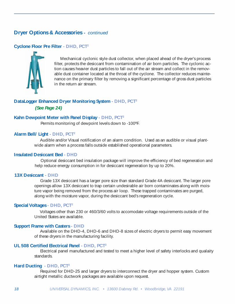
Mechanical cyclonic style dust collector, when placed ahead of the dryer’s process fi lter, protects the desiccant from contamination of air born particles. The cyclonic ac-tion causes heavier dust particles to fall out of the air stream and collect in the remov-able dust container located at the throat of the cyclone. The collector reduces mainte-nance on the primary fi lter by removing a signifi cant percentage of gross dust particles in the return air stream.
Cyclone Floor Pre Filter - DHD, PCT2
DataLogger Enhanced Dryer Monitoring System - DHD, PCT2
(See Page 24)
Insulated Desiccant Bed - DHD Optional desiccant bed insulation package will improve the effi ciency of bed regeneration and help reduce energy consumption in for desiccant regeneration by up to 20%.

20 UNIVERSAL DYNAMICS, INC. • 13600 Dabney Rd. • Woodbridge, VA 22191
Drying Hoppers
UnaDyn’s Drying Hoppers are designed to promote the mass fl ow of a wide variety of materials from virgin pellet to thin fl ake and other diffi cult-to handle regrinds. These hoppers incorporate the use of a solid cone in the hopper transition zone. The solid cone design result in better air distribution, effi cient and fast material drying, improved mass fl ow, and a hopper that is easy to clean. Standard drying hoppers up to 343 cubic feet capacity are available for use with DHD and PCT2 series dryers. Standard features for all hoppers include the following:
• Solid Mass Flow Inlet Cone • Laser Cut Access Doors • Heavy Duty Lid and Door Clamps • Insulated Side Walls and Access Door • Clear Sight Glasses • Material Drain-Out Port w/Slide Gate
• Slide Gate Material Shut-Off on discharge • Mezzanine or Stand Mounted • Designed for Easy and Quick Cleaning & Maintenance
Model Cubic Foot* Diameter Height**
TSC 200 6.7 22.0” 55.0”
TSC 300 8.6 22.0” 63.0”
TSC 400 13.5 28.0” 66.0”
TSC 600 17.5 28.0” 77.0”
TSC 800 23.5 28.0” 95.0”
TSC Hopper The TSC Drying hopper is a solid cone all stainless steel hopper. The interior has a smooth fi nish with no pellet retaining lip or ledges. The hopper has excellent air distribution and material mass fl ow characteristics. For use with DHD dryer model 4, 6 and 8.
* Capacity in Cubic Feet with Loader** Overall Height is measured from the hopper lid to the bottom hopper fl ange.
USC Hopper
Standard construction for the USC Hopper incorporates a split ring design allowing the upper two-thirds of the chamber to be completely removed from the lower section. The two sections are permanently assembled with bolts during installation. Stainless steel construction is optionally available on all sizes. USC Hoppers are ideal for applications utilizing virgin pellets, free fl owing regrinds or blends of these materials.
TSC Hopper

21www.unadyn.com • [email protected]
Model Cubic Foot* Diameter Height**
EF-1100 32 36.25” 117”
EF-1500 43 38.25” 134”
EF-2000 58 44.25” 142”
EF-2500 72 46.25” 154”f
EF-3000 86 48.25” 166”
EF-4000 115 50.25” 188”
EF-5000 143 60.25” 191”
EF-6000 172 60.25” 208”
EF-8000 230 66.25” 229”
EF-10000 286 72.25” 246”
EF-12000 343 78.25” 258”
* Capacity in Cubic Feet with Loader** Overall Height is measured from the hopper lid to the bottom hopper fl ange.
EF Hopper Designed to handle hard to fl ow materials, features 70ºF mass-fl ow solid cones; the chamber is split al-lowing lower section to be removed completely from main body section allowing easier cleaning and mainte-nance.
Drying Hoppers - continued
Model Cubic Foot* Diameter Height**
USC-1100 32 36.25” 93”
USC-1500 43 38.25” 107”
USC-2000 58 44.25” 112”
USC-2500 72 46.25” 123”
USC-3000 86 48.25” 133”
USC-4000 115 50.25” 154”
USC-5000 143 60.25” 150”
USC-6000 172 60.25” 168”
USC-8000 230 66.25” 185”
USC-10000 286 72.25” 198”
USC-12000 343 78.25” 207”
* Capacity in Cubic Feet with Loader** Overall Height is measured from the hopper lid to the hopper bottom fl ange. USC Hopper
USC Hopper - Continued
Easy Flow Hopper

22 UNIVERSAL DYNAMICS, INC. • 13600 Dabney Rd. • Woodbridge, VA 22191
FEATURE TSC USC EFSolid Cone - No perforated metal N/A
Air Tube Solid Cone - No Perforated Metal N/A N/A
Stainless Steel Internal SurfacesPolished Stainless Steel Outer Wrap N/A N/A
Drain-Out with Slide GateHopper Bottom Slide GateDouble Wall with InsulationAdditional Insulation 4” N/A
Sight GlassExtended Sight GlassAdjustable Level SensorLaser Cut Access DoorDouble Insulated Access DoorHinged Access DoorBolt on Access Door N/A
Adjustable Orientation N/A
Air Operated Orfi ce Gate Valve
DHD Model TSC USC/EF
Min Hopper Model *cuft.
Max Hopper Model *cuft.
4 x 200 6.8 800 23.5
6 x x 400 13.5 1100 32.0
8 x x 600 17.5 1500 43.0
15 x 1100 32.0 2000 58.0
25 x 2000 58.0 4000 115.0
30 x 2500 72.0 8000 230.0
40 x 3000 86.0 8000 230.0
60 x 3000 86.0 10,000 286.0
100 x 6000 172.0 Per Application
120 x 8000 230.0 Per Application
Formula for Sizing Hoppers: Minimum Hopper Cubic Foot = Pounds per Hour (PPH) x Residence Time (RT) ÷ Minimum Bulk Density (MBD) MCF = PPH x RT MBDExample: 100 pph throughput rate, 3 hour residence time, 30 pound per cubic foot bulk density 10 = 100 x 3 30 Hopper to select would be the Model TSC400
DRYING HOPPER SPECIFICATION CHART
* Capacity in cubic foot with lid mounted loader.
HOPPER FEATURE COMPARISON
Standard
Optional

23www.unadyn.com • [email protected]
Drying Hopper Options & Accessories - continued
Convertible Vacuum Tray Adapter (VTA)
Discharge assembly attached to the bottom of the drying hopper which permits the user to connect a loader to convey dried material from the drying hopper to the processing machine. Available with one or two outlet ports.
Pneumatic Slide Valve used primarily as a positive, airtight, sealing device. Most common usage is to seal the discharge throat of large, high pressure drop, drying hoppers and on the discharge throat of vacuum chambers when an air tight throat seal is needed to support the operational parameters of the vacuum conveying application.
Permits the user to set the limit of material being loaded into the drying hopper or it may also be used for low material level alarm. At no time should the material level in the hopper be set to less than 50% of the capacity of the drying hopper.
Drop Tube Style Vacuum Take Off
Discharge assembly attached to the bottom of the drying hopper that permits the user to connect a loader to convey the material from the drying hopper to the extruder or injection molding machine. Available with one or two outlets.
Box Style (VTA)
Discharge assemble attached to the bottom of the drying hopper that permits the user to connect a loading system to convey dried material from the drying hopper to the processing machine(s). Available with 3 or more outlet ports.
Powerful magnet assembly used to reduce the possibility of ferrous material being introduced into the extruder or injection molding machine. The assembly comes with manual material shutoff slide gate. Available in standard and high temperature designs to suit the application.
Vortex Shutoff Valve
Bunting Drawer Magnet with Slide Gate
Vacuum Take Off Adaptors:
Elongated Sight Glass with Adjustable Lever Sensor

24 UNIVERSAL DYNAMICS, INC. • 13600 Dabney Rd. • Woodbridge, VA 22191
Split the air fl ow between two drying hoppers. Used when drying resin in two different drying hoppers. The damper valve is used to manually adjust the air fl ow to each drying hopper, balancing the air fl ow to compensate for higher or lower pressure drops in dual drying hopper confi gurations. Individual hopper pressure is affected by type of material, fi ll level of the hopper and any operational irregulari-ties. Never open damper valves to an empty hopper.
For applications over 250ºF for when minimizing process air heat loss between the dryer and drying hopper is critical and for applications below 150ºF when controlling low process air temperature is critical to the application. Also used for central drying systems with several individual drying hoppers needing different dry-ing temperature settings.
Drying Hopper Options & Accessories - Continued
Duct Y’s with Dampers
Remote Mounted Heater
Drying Hopper Options & Accessories:
Hopper Support Stands:
Frame and Beam Design - TSC Hoppers
Simple construction and easy to expand into a multiple drying hopper confi guration. Ruggedly built with a strong beam between two end frames. Accommodates a wide range of hopper sizes. May be of fi xed or portable design. Confi gured to support single or multiple hoppers. Available with minimum clearance, drum clearance and gaylord clearance.
Structural Design - USC & EF Hoppers
Simple Heavy duty structural angle construction. Available with minimum clearance, drum clearance and gaylord clearance.

25www.unadyn.com • [email protected]
DataLogger
The Industry’s First Microprocessor Controlled Internal Event Recorder and Data Monitoring System
Features
• Sampling rate adjustable from 3 seconds to 3 minutes• Data is time and date stamped• Sample up to 48 Hour duration• Enables critical function analysis• Downloads to PC for database analysis• Uses MS Excel or similar applications• 72 hour history sampling• E-mail compatible• Excel spreadsheet fi le format• Hopper ready monitor- Green light
Benefi ts
• Verifi es proper equipment operation• Allows pro-active preventative maintenance• Easy troubleshooting• Preventative maintenance• On-line troubleshooting support
The DataLogger is the industry’s fi rst microprocessor controlled data monitoring system that re-cords event information for enhanced dryer monitoring. The system monitors 12 temperature points and 3 pressure points to help trouble shoot processing problems.
P C T DAT A S AMP L E DHD30
0
1 00
2 00
3 00
4 00
5 00
6 00 -8 0
-7 0
-6 0
-5 0
-4 0
-3 0
-2 0
-1 0
0
P rocess H ea ter Te m p era tu re
R eg en H eater Te m pe ra tu re
R etu rn A ir Te m pe ra tu re
R eg en O u tle t T em pera tu re
D rye r In le t T em pera tu re
D rye r O utle t Te m p era tu re
H op pe r T hro a t Te m pe ra tu re
Le ft B e d U p per T em p era tu re
Le ft B e d L ow er T em p era tu re
R ig h t Be d U p pe r T em p era tu re
R ig h t Be d L ow e r T em p era tu re
P rocess D ew P o in t
Verify proper equipment operation with sample testing done at adjustable rates of 3 seconds to 3 minutes. Sam-plings are time and date stamped with sample duration of the 48 hours and a 72 hour history of equipment function. Download to a PC for database analysis in an excel spreadsheet fi le format. With on-line troubleshooting support, trouble-shooting is easy and allows for pro-active preventative maintenance so problems are stopped before they start.
A sample graph of return air temperature, prior to the fi lter and cooling coil, that fl uctuates as material is delivered and cools the air. It refl ects the average return temperature and the number of loading cycles.

26 UNIVERSAL DYNAMICS, INC. • 13600 Dabney Rd. • Woodbridge, VA 22191
F.A.C.S. - Factory Acquisition Control System
UnaDyn Distributed Control Process Management System
FACS permits plant-wide control of material conveying systems as well as monitoring of most SPI compatible equipment such as mold temperature control units, chillers, dryers and blenders. The two-wire power and communications network, in conjunction with the Windows platform, makes this system economical to install, easy to setup and operate, simple to expand and reconfi gure. Through a PC or the compatible Allen Bradley or Sieman PLCs with touchscreen displays, the user can control or monitor system performance from the plant fl oor or from remote locations. Users can import drawings and pictures to show system confi gurations or location of equipment. With process chain analysis and verifi cation you can set up, monitor and record setpoints, equipment perfor-mance, defi ne material fl ow paths and equipment selection with a single command. FACS has full graphing capabilities and a built in SQL Database to process all your information and store it with a complete set of reports for immediate or future use. FACS may be connected to a wired or wireless network and has Factory Direct Support and Fac-tory Direct E-mail to any auxiliary equipment manufacturer with a full set of reports.
F. A. C. S.

28 UNIVERSAL DYNAMICS, INC. • 13600 Dabney Rd. • Woodbridge, VA 22191
RECOMMENDED DRYING CONDITIONS HYGRO-SCOPIC
ACRONYM OR COMMON NAME
RECOM-MENDED (HRS)
DEG. In F
NOTES CHEMICAL DESCRIPTION TRADE NAME (MANUFAC-TURER)
YES ABS (molding grade) 2-3 190-200 1,2 Acrylonitrile-Butadiene-Styrene Terpolymer
Cycolac Lustran
YES ABS (extrusion grade) 3-4 180-200 1,4 Acrylonitrile-Butadiene-Styrene Terpolymer
Cycolac Lustran
YES ABS/PC 4-5 220-230 1,2 ABS/Polycarbonate alloy Cycolac Lustrain
YES ABS/PVC 2-3 160-170 1,2 ABS/PVC alloy Cycolac Lustrain
YES Acrylic 2-3 170-190 1 (also Methyl Methacrylate) Lucite Plexiglas
YES EVOH 2-3 195-225 1 Ethylene-Vinyl Alcohol copolymer EVAL
NO HDPE 1-2 160-180 1,2 High Density (linear) Polyethyl-ene
-various-
YES HDPE w/max. 3% black 3-4 160-180 1,2 High Density (linear) Polyethyl-ene
-various-
YES HDPE w/max. 40% black 4-5 160-180 1,2 High Density (linear) Polyethyl-ene
-various-
This listing of recommended drying conditions are intended for quick sizing of UnaDyn drying systems. The list is as complete as possible, but one should always be guided by the customer’s experience and/or the material supplier’s recommendations.
Two known variables are necessary to size a system: MATERIAL and THROUGHPUT, without one, the other is insuffi cient. There is no such thing as a “nylon dryer”, for example, and when someone specifi es a “250 lb/hr dryer”, the question is: “250 bl/hr of what material”?
MATERIAL: The chart lists many common hygroscopic and non-hygroscopic plastic materials by their acronym or com-mon name, chemical or general description, and some (but not all) trade names and their suppliers. This is the starting point in sizing a system. Remember that the air in the drying hopper must be able to fl ow through the material, and the more air space between the plastic particles, the more effi cient the drying. Most ground scrap is acceptable, if mixed with at least 50% virgin pellets. If the regrind is dusty, a pre-fi lter cyclone should be used to keep the dust out of the desiccant beds, and to ensure optimum air fl ow through the system.
THROUGHPUT: Careful determination of the system’s throughput, in terms of the capacity of the processing machine(s), is most important. Sizing for too low a throughput will result in poor drying; sizing too high can make the system too expensive. When several materials will be used in the same system, use the material with the longest drying time as the criterion, but be sure to adjust the processing machine’s capac-ity accordingly. If the machine throughput is not known, use the following as guide lines only (all through puts are MAXIMUM):
Extruders (in ABS)
Blow Molders: Use 50% of the capacity of the extruder, from the chart above.
Recommended Drying Conditions
SCREW 1” 1 1/2” 2” 2 1/2” 3” 3 1/3” 4” 4 1/2” 6” 8”
LB/HR 100 150 200 300 500 750 1000 13000 2150 3000
Injection Molders (in ABS)
TON CLAMP 75 125 150 200 300 400 500 750 1000 1500 2000
SHOT 2-3 3-4 4-6 6-8 12-14 20-30 36-48 80-120 150-225 250-300 325-400
LB/HR 20 30 45 55 90 140 250 400 500 600 750

29www.unadyn.com • [email protected]
HYGRO-SCOPIC
ACRONYM OR COMMON NAME
RECOM-MENDED (HRS)
DEG. In F
NOTES CHEMICAL DESCRIPTION TRADE NAME (MANUFAC-TURER)
YES HDPE w/black (cable extr.)
5-6 140-150 3 High Density (linear) Polyethyl-ene (special UCC grade)
UCC
YES Ionomer 7-8 150-160 1,2,3 Ionomer resin Surlyn
NO LDPE 1-2 160-180 1,2 Low Density (conventional) Polyethylene
-various-
YES LDPE w/max. 3% black 3-4 160-180 1,2 Low Density (conventional) Polyethylene
-various-
YES LDPE w/max. 40% black 4-5 160-180 1,2 Low Density (conventional) Polyethylene
-various-
YES Nylon 6, 6/6, 612 5-6 160-180 1,2,7 Crystalline Nylon (Caprolactan) Zytel Vydene Capron
YES Nylon (amorphous) 4-5 170-180 1,2,7 Super Tough Nylon ZytelST
YES Nylon (transparent) 4-5 180-190 1,7 Transparent Nylon Zytel330
YES OSA 2-3 180-190 1 Olefi n-modifi ed Styrene-Acryloni-trile copolymer
OSA)
YES PBT 2-3 250-270 1,2 Polybutylene-Terephthalate Celanex Valox420
YES PBT/PLA 4-5 350-370 1,2 PBT/PLA alloy Valox815
YES PC 3-4 250-270 1,2 Polycarbonate Lexan Merlon
YES PC/PBT/E 3-4 250-270 1 Polycarbonate/PBT/Elastomer alloy
Xenoy
YES PCS 2-3 220-230 1 Polycarbonate-Styrene copoly-mer
Arloy Cycoloy
YES PCTA 3-4 160-180 1 Cyclohexane-Terephthalate copolymer
Kodapak
YES PEEK 3-4 300-320 1,2 Polyetheretherketone PEEK
YES PEM 4-5 300-320 1,2 Polyerhermide Ultem
YES PES 3-4 300-320 1,2 Polyethersulfone PES
YES PLA 4-5 320-350 1,2 Polyethylene-Terephthalate (Thermoplastic Polyester)
Valox 700,800 Cleartuf, Vicuf
YES PLA (Rynite) 3-4 270-280 1,2 Polyethylene-Terephthalate (Thermoplastic Polyester)
Rynite
YES PLA (beverage bottles) 5-6 340-350 1,3 Polyethylene-Terephthalate (Thermoplastic Polyester)
Kodapak
YES PLAG 3-4 140-150 1,3 Amorphous PLA copolymer Kodar
YES Polyarylate 5-6 250-260 1,2 Amorphous Aromatic Polyester Occidental
YES Polysulfone 4-5 250-260 1,2 (also Polyether, Polyarylsulfone) Silane Astrel Udel
YES Polyurethane 2-3 180-200 1 Polyurethane Elastomer Isonate Estane
NO PP 1-2 170-190 1,2 Polypropylene -various-
YES PPC 3-4 260-270 1 Polyphthalate carbonate Lexan
YES PPO 2-3 200-220 1,2 Polyphenylene Oxide Nory
YES PPS 2-3 270-280 1,2 Polyphenylene Sulfi de Ryton
NO PS (styrene) 1-2 180-190 1 Polystrene -various-
YES SAN (modifi ed) 3-6 185-160 1 Styrene-Acrlonitrike (with olefi n elastomey)
Rovel
YES SMA 2-3 200-210 1 Styrene-Maleic Anhydride Dylark
YES TPE 2-3 210-220 1,2 Thermoplastic Polyester Hytrel
YES TPR 2-3 150-170 1,2,3 Thermoplastic Rubber Santoprene
YES XLPE 3-4 120 Crosslink PE
YES XT 3-4 170-190 1,2 Impact-modifi ed Acrylic Resin Cyro
Recommended Drying Conditions - Continued

DH
D E
LEC
TRIC
DRY
ER S
PEC
IFIC
ATIO
NS
D
HD
-4D
HD
-6D
HD
-8D
HD
-11
DH
D-1
5D
HD
-25
DH
D-3
0D
HD
-40
DH
D-6
0D
HD
-100
DH
D-1
20D
HD
-150
DH
D-1
80
PR
OC
ES
S A
IRF
LOW
(cf
m fr
ee fl
ow)
125
250
350
450
600
900
1250
1500
1800
2500
3000
3500
4500
PR
OC
ES
S L
INE
SIZ
E (
dia.
-in)
3 7/
83
7/8
5 7/
85
7/8
7 7/
87
7/8
7 7/
87
7/8
7 7/
89
7/8
9 7/
816
18
WE
IGH
T (
lb)
940
1,00
0 1,
100
1,40
0 1,
800
2,20
0 3,
000
3,50
0 4,
000
6,00
0 8,
000
16,0
00
18,0
00
PO
WE
R R
EQ
UIR
ED
(kv
a)(s
td. t
emp.
)17
1933
4143
7510
114
115
620
429
136
847
0
PO
WE
R R
EQ
UIR
ED
(kv
a)(h
igh
tem
p.)
1726
4348
5898
131
179
201
279
359
428
650
CO
OLI
NG
CO
IL W
AT
ER
FLO
W (
gpm
)4
to 6
4 to
68
to 1
28
to 1
212
to 1
818
to 2
418
to 2
424
to 2
824
to 2
848
to 5
448
to 5
454
to 6
054
to 6
0
DH
D G
AS
DRY
ER S
PEC
IFIC
ATIO
NS
DH
D-6
GF
DH
D-8
GF
DH
D-1
1GF
DH
D-1
5GF
DH
D-2
5GF
DH
D-3
0GF
DH
D-4
0GF
DH
D-6
0GF
DH
D-1
00G
FD
HD
-120
GF
DH
D-1
50G
FD
HD
-180
GF
* P
RO
CE
SS
AIR
FLO
W (
cfm
free
f.)
250
350
450
600
900
1250
1500
1800
2500
3000
3500
4500
PR
OC
ES
S L
INE
SIZ
E (
dia.
-in)
3 7/
85
7/8
5 7/
87
7/8
7 7/
87
7/8
7 7/
87
7/8
9 7/
89
7/8
1618
WE
IGH
T (
lb)
1,00
0 1,
100
1,40
0 1,
800
2,20
0 3,
000
3,50
0 4,
000
6,00
0 8,
000
16,0
00
18,0
00
PO
WE
R R
EQ
UIR
ED
(kv
a)8
8 8
10
13
16
28
28
38
48
57
69
GA
S C
ON
SU
MP
TIO
N (
cfh)
(1-
5 ps
i pr
essu
re r
eq’d
)30
4661
6910
513
817
220
720
733
144
166
1
CO
OLI
NG
CO
IL W
AT
ER
FLO
W (
gpm
)4
to 6
8 to
12
8 to
12
12 to
18
18 to
24
18 to
24
24 to
28
24 to
28
48 to
54
48 to
54
54 to
60
54 to
60
* P
roce
ss a
ir fl o
w is
bas
ed o
n fr
ee fl
ow in
the
hopp
er.
Whe
n ca
lcul
atin
g th
e ac
tual
air
fl ow
in a
pro
cess
with
mat
eria
l in
the
hopp
er, D
ER
AT
E th
e fr
ee fl
ow b
y 20
%.
• S
tand
ard
Tem
pera
ture
ran
ge is
180
ºF -
250
ºF
30 UNIVERSAL DYNAMICS, INC. • 13600 Dabney Rd. • Woodbridge, VA 22191
MO
DE
L
DIM
EN
SIO
NS
CF
M
VO
LTA
GE
DH
D-4
*63
”H X
60”
W X
42”
D12
5
230
or 4
60
DH
D-6
68”H
X 6
0”W
X 6
5”D
250
“
DH
D-8
73”H
X 6
0”W
X 4
5”D
350
“
DH
D-1
184
”H X
86”
W X
56”
D45
0 46
0
DH
D-1
592
”H X
96”
W X
59”
D60
0 “
DH
D-2
597
”H X
129
”W X
71”
D90
0 “
DH
D-3
010
0”H
X 1
39”W
X 7
8”D
1250
“
DH
D-4
010
3”H
X 1
39”W
X 7
9”D
1500
“
DH
D-6
010
4”H
X 1
53”W
X 8
3”D
1800
“
DH
D-1
0010
8”H
X 1
23”W
X 8
0”D
2500
“
DH
D-1
2012
3”H
X 1
54”W
X 8
7”D
3000
“
DH
D-1
5014
4”H
X 2
00”W
X 9
4”D
3500
“
DH
D-1
8015
0”H
X 2
23”W
X 1
12”D
4500
“
DH
D E
LEC
TRIC
AN
D G
AS
DIM
ENSI
ON
S, C
FM A
ND
VO
LTA
GE
* D
HD
-4 A
vaila
ble
in E
lect
ric O
nly.
Add
ition
al V
olta
ges
Ava
ilabl
e
DH
D
Mod
elTS
C
USC
/EF
Min
Hop
per
M
odel
*
cuft
.M
ax H
oppe
r M
odel
*
cuft
.
4x
200
6.8
800
23.5
6x
x40
013
.511
0032
.0
8x
x60
017
.515
0043
.0
15x
1100
32.0
2000
58.0
25x
2000
58.0
4000
115.
0
30x
2500
72.0
8000
230.
0
40x
3000
86.0
8000
230.
0
60x
3000
86.0
10,0
0028
6.0
100
x60
0017
2.0
Per
Ap
plic
atio
n
120
x80
0023
0.0
Per
Ap
plic
atio
n
DRY
ING
HO
PPER
SPE
CIF
ICAT
ION
CH
ART
* C
apac
ity in
cub
ic fo
ot w
ith lo
ader
.

300
600
1000
1250
1500
2000
2500
3000
AIR
FR
EE
FLO
W30
0 C
FM
/50
0 m
3/h
600
CF
M /
1000
m3/
h10
00 C
FM
/17
00 m
3/h
1250
CF
M /
2100
m3/
h15
00 C
FM
/25
00 m
3/h
2000
CF
M /
3400
m3/
h20
00 C
FM
/42
00 m
3/h
3000
CF
M /
5000
m3/
h
WE
IGH
T30
00 lb
s /
1400
kg
3500
lbs
/16
00 k
g50
00 lb
s /
2300
kg
5500
lbs
/25
00 k
g60
00 lb
s /
2700
kg
8500
lbs
/39
00 k
g90
00 lb
s /
4082
kg
9500
lbs
/43
09 k
g
PR
OC
ES
S D
UC
T S
IZE
6”/1
50 m
m6”
/150
mm
8”/2
00 m
m8”
/200
mm
8”/2
00 m
m10
”/25
0 m
m10
”/25
0 m
m10
”/25
0 m
m
TO
TAL
LOA
D44
.4 k
va61
.8 k
va10
3.7
kva
139.
1 kv
a18
7.5
kva
199
kva
250
kva
287
kva
CO
OLI
NG
WA
TE
R
RE
QU
IRE
ME
NT
8 -
12 g
pm12
- 1
8 g
pm18
- 2
4 g
pm18
- 2
4 g
pm24
- 2
8 g
pm24
- 2
8 g
pm48
- 5
4 g
pm48
- 5
4 g
pm
PCT2
ELEC
TRIC
DRY
ER S
PEC
IFIC
ATIO
NS
Sys
tem
des
igne
d fo
r op
erat
ion
up to
300
0ft/1
000m
abo
ve s
ea le
vel -
Oth
er e
leva
tions
mus
t be
spec
ifi ed
at t
ime
of p
urch
ase!
460/
3/60
Vol
tage
is s
tand
ard
- ot
her
volta
ges
avai
labl
e, c
onsu
lt fa
ctor
y fo
r de
tails
Com
pres
sed
Air:
80-
120
psig
/5-8
bar
Sta
ndar
d Te
mpe
ratu
re R
ange
: 16
0º -
375
º F
ahre
nhei
t (71
º -
191º
Cel
sius
)G
AS
ON
LY:
Gas
Pre
ssur
e R
equi
red
- 0.
5 ps
ig to
1/5
psi
g -
34.5
mba
r to
103
mba
r ov
erpr
essu
re
31www.unadyn.com • [email protected]
300
600
1000
1250
1500
2000
2500
3000
AIR
FR
EE
FLO
W30
0 C
FM
/50
0 m
3/h
600
CF
M /
1000
m3/
h10
00 C
FM
/17
00 m
3/h
1250
CF
M /
2100
m3/
h15
00 C
FM
/25
00 m
3/h
2000
CF
M /
3400
m3/
h25
00 C
FM
/42
00 m
3/h
3000
CF
M /
5000
m3/
h
WE
IGH
T30
00 lb
s /
1400
kg
3500
lbs
/16
00 k
g50
00 lb
s /
2300
kg
5500
lbs
/25
00 k
g60
00 lb
s /
2700
kg
8500
lbs
/39
00 k
g85
00 lb
s /
3900
kg
8500
lbs
/39
00 k
g
PR
OC
ES
S D
UC
T S
IZE
6”/1
50 m
m6”
/150
mm
8”/2
00 m
m8”
/200
mm
8”/2
00 m
m10
”/25
0 m
m10
”/25
0 m
m10
”/25
0 m
m
TO
TAL
LOA
D6.
2 kv
a7.
6 kv
a11
.0 k
va13
.3 k
va23
.0 k
va38
kva
38 k
va43
kva
CO
OLI
NG
WA
TE
R
RE
QU
IRE
ME
NT
8 -
12 g
pm12
- 1
8 g
pm18
- 2
4 g
pm18
- 2
4 g
pm24
- 2
8 g
pm24
- 2
8 g
pm48
- 5
4 g
pm48
- 5
4 g
pm
TO
TAL
GA
S C
ON
-SU
MP
TIO
N12
CF
H26
6 C
FR
H37
8 C
FH
530
CF
H62
1 C
FH
800
CF
H90
0 C
FH
1100
CF
H
PCT2
GA
S D
RYER
SPE
CIF
ICAT
ION
S
MO
DE
L
DIM
EN
SIO
NS
+ h
eig
ht
for
har
d d
uct
ing
VO
LTS
PC
T2 -
300
82”H
X 3
4.5”
W X
65.
5”D
6”46
0/3/
60
PC
T2 -
600
82”H
X 3
4.5”
W X
65.
5”D
10”
“
PC
T2 -
1000
96.2
5”H
X 4
8”W
X 1
08”D
15.7
5”“
PC
T2 -
1250
96.2
5”H
X 4
8”W
X 1
08”D
15.7
5”
“
PC
T2 -
1500
96.2
5”H
X 4
8”W
X 1
08”D
15.7
5”
“
PC
T2 -
2000
103.
13”H
X 6
0”W
X 1
38”D
19”
“
PC
T2 -
2500
103.
13”H
X 6
0”W
X 1
38”D
19”
“
PC
T2 -
3000
103.
13”H
X 6
0”W
X 1
38”D
19”
“
Add
ition
al V
olta
ges
Ava
ilabl
e
PCT2
ELEC
TRIC
AN
D G
AS
DIM
ENSI
ON
S, H
AR
D D
UC
TIN
G H
EIG
HT
AN
D V
OLT
AG
E

UNIVERSAL DYNAMICS, INC.A Company of MANN+HUMMEL
13600 Dabney RoadWoodbridge, Virginia 22191-1446 (USA)1-703-491-2191 • Fax 1-703-490-7001
www.unadyn.come-mail: [email protected]
System Engineering Worldwide
Call Today For More Information:
1-888-494-8386
UNIVERSAL DYNAMICS, INC.
Una-DynDecades of innovation, expertise and product excel-
lence has positioned Una-Dyn as the leader in
material handling systems for the plastics industry.
Quick changeover, low maintenance, efficient opera-
tion and dependability are built into every product
and system. As a Una-Dyn customer you will appre-
ciate our unique modular approach to product
design.
Think Una-Dyn next time you want to expand,
upgrade or replace equipment. You’ll find a com-
plete family of products and systems. There is a
solution for every budget and operation.
Discover why more plastics manufacturers world-
wide place their trust in Una-Dyn.