
SPRAY-DRYING CELLULOSE NANOFIBRILS: EFFECT OF DRYING ...
14
SPRAY-DRYING CELLULOSE NANOFIBRILS: EFFECT OF DRYING PROCESS PARAMETERS ON PARTICLE MORPHOLOGY AND SIZE DISTRIBUTION Yucheng Peng{ Graduate Research Assistant E-mail: [email protected] Yousoo Han Assistant Research Professor E-mail: [email protected] Douglas J. Gardner*{ Professor of Wood Science and Technology AEWC Advanced Structures and Composites Center School of Forest Resources University of Maine Orono, ME 04469-5793 E-mail: [email protected] (Received May 2012) Abstract. Spray-drying was chosen as an appropriately scalable manufacturing method to dry cellulose nanofibril (CNF) suspensions. Spray-drying of two different types of CNF suspensions—nanofibrillated cellulose (NFC) and cellulose nanocrystals (CNC)—was carried out using a laboratory-scale spray dryer. Effects of three spray-drying process parameters on particle morphology and particle size distribution were evaluated: 1) gas flow rate; 2) liquid feed rate; and 3) suspension solids concentration. Particle morphology was characterized by scanning electron microscopy (SEM) and a morphology analyzer. SEM showed that spray-drying of NFC formed fibrous particles and fibrous agglomerates, whereas spray-drying CNCs pro- duced spherical and mushroom cap (or donut)-shaped particles. Particle morphology formation mecha- nisms are proposed for spray-drying nanocellulose suspensions. The effect of the three spray-drying process parameters on particle size distribution depended on the drying nature of the materials. The three parameters interacted to significantly affect particle size of CNC suspensions, whereas they did not interact to affect particle size of NFC suspensions. For the CNC suspension, a higher gas flow rate produced smaller particle sizes. The gas flow rate did not affect particle size for NFC suspensions. The effect of liquid feed rate and solids concentration on CNF particle size was negligible in this study. The smallest mean circle equivalent diameters produced in this study were 3.95 mm for NFC and 3.64 mm for CNC. Keywords: Nanocellulose, spray-drying, particle morphology, particle size distribution. INTRODUCTION The intensive research of cellulose nanofibrils (CNF) and their application as a reinforcing com- ponent in polymer composites have received con- siderable attention (Beecher 2007; Hubbe et al 2008; Eichhorn et al 2010; Habibi et al 2010; Siro and Plackett 2010; Siqueira et al 2010; Klemm et al 2011; Moon et al 2011). Because of their hydrophilic nature and propensity to agglomerate, a major processing challenge is to properly dry CNF from aqueous suspen- sions (Gardner et al 2008). In a previous study (Peng et al 2012), spray-drying was proposed as a technically appropriate manufacturing pro- cess for drying nanocellulose suspensions. Particle morphology and particle size distribution are two critical factors in determining properties of dried powders (wettability, stability, and cohe- siveness or dispersability) and their applications in * Corresponding author { SWST member Wood and Fiber Science, 44(4), 2012, pp. 448-461 # 2012 by the Society of Wood Science and Technology
Transcript of SPRAY-DRYING CELLULOSE NANOFIBRILS: EFFECT OF DRYING ...

SPRAY-DRYING CELLULOSE NANOFIBRILS: EFFECT OF DRYING
PROCESS PARAMETERS ON PARTICLE MORPHOLOGY
AND SIZE DISTRIBUTION
Yucheng Peng{Graduate Research Assistant
E-mail: [email protected]
Yousoo HanAssistant Research Professor
E-mail: [email protected]
Douglas J. Gardner*{Professor of Wood Science and Technology
AEWC Advanced Structures and Composites Center
School of Forest Resources
University of Maine
Orono, ME 04469-5793
E-mail: [email protected]
(Received May 2012)
Abstract. Spray-drying was chosen as an appropriately scalable manufacturing method to dry cellulose
nanofibril (CNF) suspensions. Spray-drying of two different types of CNF suspensions—nanofibrillated
cellulose (NFC) and cellulose nanocrystals (CNC)—was carried out using a laboratory-scale spray dryer.
Effects of three spray-drying process parameters on particle morphology and particle size distribution were
evaluated: 1) gas flow rate; 2) liquid feed rate; and 3) suspension solids concentration. Particle morphology
was characterized by scanning electron microscopy (SEM) and a morphology analyzer. SEM showed that
spray-drying of NFC formed fibrous particles and fibrous agglomerates, whereas spray-drying CNCs pro-
duced spherical and mushroom cap (or donut)-shaped particles. Particle morphology formation mecha-
nisms are proposed for spray-drying nanocellulose suspensions. The effect of the three spray-drying process
parameters on particle size distribution depended on the drying nature of the materials. The three parameters
interacted to significantly affect particle size of CNC suspensions, whereas they did not interact to affect
particle size of NFC suspensions. For the CNC suspension, a higher gas flow rate produced smaller particle
sizes. The gas flow rate did not affect particle size for NFC suspensions. The effect of liquid feed rate and
solids concentration on CNF particle size was negligible in this study. The smallest mean circle equivalent
diameters produced in this study were 3.95 mm for NFC and 3.64 mm for CNC.
Keywords: Nanocellulose, spray-drying, particle morphology, particle size distribution.
INTRODUCTION
The intensive research of cellulose nanofibrils(CNF) and their application as a reinforcing com-ponent in polymer composites have received con-siderable attention (Beecher 2007; Hubbe et al2008; Eichhorn et al 2010; Habibi et al 2010;Siro and Plackett 2010; Siqueira et al 2010;Klemm et al 2011; Moon et al 2011). Because
of their hydrophilic nature and propensity toagglomerate, a major processing challenge isto properly dry CNF from aqueous suspen-sions (Gardner et al 2008). In a previous study(Peng et al 2012), spray-drying was proposedas a technically appropriate manufacturing pro-cess for drying nanocellulose suspensions.
Particle morphology and particle size distributionare two critical factors in determining propertiesof dried powders (wettability, stability, and cohe-siveness or dispersability) and their applications in
* Corresponding author{ SWST member
Wood and Fiber Science, 44(4), 2012, pp. 448-461# 2012 by the Society of Wood Science and Technology

composites (Vehring 2007; Moczo and Pukanszky2008). Different particle morphologies and sizeswith desired physical properties can be generatedby manipulating the spray-drying process param-eters (Nandiyanto and Okuyama 2011). Gen-erally, six unit operations are involved in aspray-drying process: 1) preconcentration of theliquid; 2) atomization; 3) dehydration in a streamof hot gas; 4) powder separation; 5) cooling; and6) packaging. Among the six unit operations,four mainly determined the particle morphology:preconcentration of the liquid feed, atomization,hot air drying, and cyclone separation. Precon-centration of the feeding liquid to an appropriateviscosity is a required first step. Higher solidsconcentration of the suspension produces largerparticle sizes. At the same time, the specific dryingnature of a liquid, liquid viscosity, liquid density,and surface tension also influences the particleproperties (Nukiyama and Tanasawa 1938; Kimand Marshall 1971; Kumar and Prasad 1971;Rizkalla and Lefebvre 1975; Lefebvre 1989;Walton andMumford 1999; Schick 2006; Vehring2007; Hede et al 2008). Phenomenological studiesof spray-dried particles showed that morphologieswere dependent on the type of materials: 1) spheri-cal particles for most materials; 2) agglomeratesfor aluminum oxide; 3) hollow (skin-forming)particles for coffee; 4) mushroom cap-shapedparticles for glycoprotein, etc. The mean dropletsize increased with an increase in liquid vis-cosity and liquid surface tension and decreasedas liquid density increased. Because the liquidsuspension was pumped through the atomizationsystem, design variables of the atomizer (liquidorifice diameter and nozzle angle) and the oper-ating variables (liquid feed rate and gas flowrate) can be controlled to generate particles withdifferent morphologies (Kim and Marshall 1971;Kumar and Prasad 1971; Hede et al 2008). Thesprayed droplet size increased with increases inliquid feed rate and decreased as gas flow rateincreased. However, all the studies were based onspecific atomization systems. Different materialsmay perform differently with different atomizers.There is no agreement among researchers relat-ing the variation of droplet size among processvariables. Interactions among all the variables
make agreement impossible. As the atomizedsprays flow along the drying chamber in contactwith the hot gas, movement of moisture in thedroplet may cause particles to inflate, distort, orshrink. Depending on the nature of the materials,the drying surface of the droplet may movefaster or slower than the dissolved or suspendedcomponents. These behaviors contribute to thedifferent mechanisms forming the dried particles(Vehring 2007). The last unit operation affectingdropletmorphology is the cyclone separation. Verysmall particles can be aspirated to the exhaust orcollected using an electrostatic precipitator.
Given a spray dryer with a pneumatic two-fluidatomization system, three operating variablesmainly determine the dried particle morphology:1) CNF suspension concentration; 2) liquid feedrate; and 3) gas flow rate. The overall goal ofthis study was to provide insight into the fun-damentals of spray-drying nanocellulose sus-pensions. The objectives were 1) to produce thesmallest particle size of CNF by manipulatingthe three process variables; and 2) to quantifythe obtained particle morphology.
EXPERIMENTAL
Materials
Two CNF suspensions were studied: 1) a com-mercial product of nanofibrillated cellulose (NFC)suspension ARBOCEL MF40-10 at 10 wt %from J. Rettenmaier & Sohne GMBHþCO.KG(Rosenberg, Germany); and 2) a cellulose nano-crystal (CNC) suspension at 6.5 wt % from theUSDA Forest Service, Forest Products Labora-tory (Madison, WI). Spray-drying of CNF sus-pensions was conducted using a laboratory-scaledryerMini SprayDryer B-290 (Buchi, Switzerland).High-purity nitrogen gas was injected to formthe suspension droplets.
Experimental Design of Spray-Drying
Cellulose Nanofibril Suspensions
Experiments were designed to evaluate effectsof the three process parameters on particle mor-phology and particle size distribution: 1) gas
Peng et al—DRYING PROCESS EFFECTS ON CELLULOSE NANOFIBRILS 449
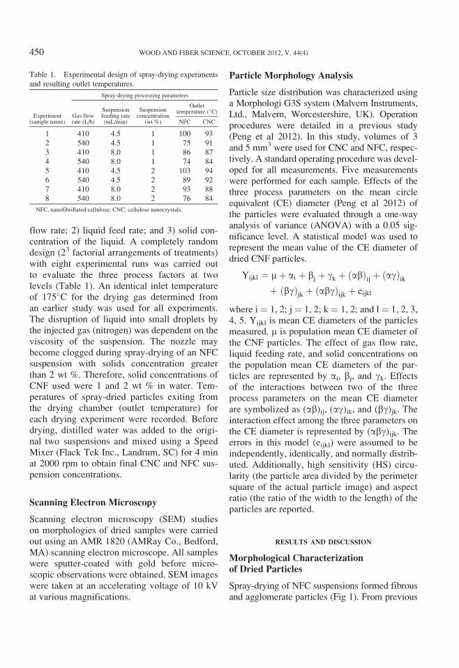
flow rate; 2) liquid feed rate; and 3) solid con-centration of the liquid. A completely randomdesign (23 factorial arrangements of treatments)with eight experimental runs was carried outto evaluate the three process factors at twolevels (Table 1). An identical inlet temperatureof 175�C for the drying gas determined froman earlier study was used for all experiments.The disruption of liquid into small droplets bythe injected gas (nitrogen) was dependent on theviscosity of the suspension. The nozzle maybecome clogged during spray-drying of an NFCsuspension with solids concentration greaterthan 2 wt %. Therefore, solid concentrations ofCNF used were 1 and 2 wt % in water. Tem-peratures of spray-dried particles exiting fromthe drying chamber (outlet temperature) foreach drying experiment were recorded. Beforedrying, distilled water was added to the origi-nal two suspensions and mixed using a SpeedMixer (Flack Tek Inc., Landrum, SC) for 4 minat 2000 rpm to obtain final CNC and NFC sus-pension concentrations.
Scanning Electron Microscopy
Scanning electron microscopy (SEM) studieson morphologies of dried samples were carriedout using an AMR 1820 (AMRay Co., Bedford,MA) scanning electron microscope. All sampleswere sputter-coated with gold before micro-scopic observations were obtained. SEM imageswere taken at an accelerating voltage of 10 kVat various magnifications.
Particle Morphology Analysis
Particle size distribution was characterized usinga Morphologi G3S system (Malvern Instruments,Ltd., Malvern, Worcestershire, UK). Operationprocedures were detailed in a previous study(Peng et al 2012). In this study, volumes of 3and 5 mm3 were used for CNC and NFC, respec-tively. A standard operating procedure was devel-oped for all measurements. Five measurementswere performed for each sample. Effects of thethree process parameters on the mean circleequivalent (CE) diameter (Peng et al 2012) ofthe particles were evaluated through a one-wayanalysis of variance (ANOVA) with a 0.05 sig-nificance level. A statistical model was used torepresent the mean value of the CE diameter ofdried CNF particles.
Yijkl ¼ mþ ai þ bj þ gk þ abð Þij þ agð Þikþ bgð Þjk þ abgð Þijk þ eijkl
where i ¼ 1, 2; j ¼ 1, 2; k ¼ 1, 2; and l ¼ 1, 2, 3,4, 5. Yijkl is mean CE diameters of the particlesmeasured. m is population mean CE diameter ofthe CNF particles. The effect of gas flow rate,liquid feeding rate, and solid concentrations onthe population mean CE diameters of the par-ticles are represented by ai, bj, and gk. Effectsof the interactions between two of the threeprocess parameters on the mean CE diameterare symbolized as (ab)ij, (ag)ik, and (bg)jk. Theinteraction effect among the three parameters onthe CE diameter is represented by (abg)ijk. Theerrors in this model (eijkl) were assumed to beindependently, identically, and normally distrib-uted. Additionally, high sensitivity (HS) circu-larity (the particle area divided by the perimetersquare of the actual particle image) and aspectratio (the ratio of the width to the length) of theparticles are reported.
RESULTS AND DISCUSSION
Morphological Characterization
of Dried Particles
Spray-drying of NFC suspensions formed fibrousand agglomerate particles (Fig 1). From previous
Table 1. Experimental design of spray-drying experiments
and resulting outlet temperatures.
Experiment(sample name)
Spray-drying processing parameters
Gas flowrate (L/h)
Suspensionfeeding rate(mL/min)
Suspensionconcentration
(wt %)
Outlettemperature (�C)
NFC CNC
1 410 4.5 1 100 93
2 540 4.5 1 75 91
3 410 8.0 1 86 87
4 540 8.0 1 74 84
5 410 4.5 2 103 94
6 540 4.5 2 89 92
7 410 8.0 2 93 88
8 540 8.0 2 76 84
NFC, nanofibrillated cellulose; CNC, cellulose nanocrystals.
450 WOOD AND FIBER SCIENCE, OCTOBER 2012, V. 44(4)

Figure 1. Scanning electron microscopy micrographs of spray-dried nanofibrillated cellulose as a function of different
process parameters.
Peng et al—DRYING PROCESS EFFECTS ON CELLULOSE NANOFIBRILS 451

research (Peng et al 2012), NFC exhibiting bothneedle-like fibril shape and large cell wall sec-tions (chunks) occurred in the original suspen-sion. After spray-drying, single large cell wallsections were obtained separately (Fig 1b) in dryform particles with a width in the range of 2-4 mmand length from 4-10 mm. A few particles withlengths about 20 mm were also observed (Fig 1).Morphology of the dried particles in this sizerange is mainly determined by the original par-ticle size and morphology. Fibril particles withdiameters about 300-400 nm were also observedin Fig 1. With different spray-drying parameters,different particle morphologies were obtained. Forspray-drying conducted at the same liquid feedrate (4.5mL/min) and solid concentration (1wt%),most of the particles were separated fibrousmaterials under a higher gas flow rate 540 L/h(Sample 2 in Fig 1), whereas agglomerates andfibrous materials occurred for samples dried undera lower gas flow rate of 410 L/h (Sample 1 inFig 1). Observations of Fig 1c-h indicated thatdifferent spray-drying parameters formed parti-cles with various proportions of fibrous materialsand agglomerates. More agglomerates appearedto be produced for suspensions dried at a higherliquid feed rate (8 mL/min) (Fig 1c, d, g, and h).More moisture needs to be evaporated per unittime at a higher liquid feed rate, causing theevaporation rate to decrease. Moisture content ofthe powders would increase, and more agglomer-ates would form. This hypothesis can be sup-ported by examining outlet temperatures of thespray-dried particles. Under the same gas flowrate and solids concentration, the outlet tem-perature of the suspension dried with a higherliquid feed rate (8 mL/min) was lower than thosedried at a lower liquid feed rate (4.5 mL/min)(Table 1). The outlet temperature is the maxi-mum temperature the collected powders experi-enced during spray-drying. The lower the outlettemperature, the higher the residue moisture con-tent of the dried particles.
SEM micrographs of the spray-dried CNC areshown in Fig 2. All the dried CNC particlesexhibited similar morphology. Most particleswere irregular with external voids. A small por-
tion of spherical particles is also discernible ineach micrograph. In addition, the spherical par-ticles were smaller than the irregular-shapedparticles. The length of CNC particles is gener-ally between several hundred nanometers tomore than 10 mm. Spherical particles were lessthan 1 mm in size, whereas irregular-shaped par-ticles ranged from 1 to more than 10 mm. Someirregular particles had mushroom cap shapes(Fig 2e, g, and h), whereas some were doughnut-shaped with a bottom layer (Fig 2). Based onobservations of the size and shape of the driedCNC, spherical particles were expected to besolid. The original CNC in aqueous suspensionexhibited needle-like fibrils (Peng et al 2012).After spray-drying, the needle-like fibrils agglom-erate to form spherical and irregular particles withminimum particle size equal to or greater than thelength of original CNC fibrils. In some instances,small spherical particles were located inside themushroom cap-shaped particles (Fig 2f-h). Con-sistent with drying NFC, the outlet temperaturefor drying CNC at the 8-mL/min feed rate waslower than those dried at a feed rate of 4.5 mL/minwith the same gas flow rate and suspensionsolids concentration.
Proposed Particle Formation Mechanisms
As the NFC suspension flowed through theatomization system, two different droplets wereformed in the drying chamber (Fig 3). Becauseof the original size and morphology of theNFC fibrils in suspension, long and large cellwall sections coexisted with relatively short andskinny NFC fibrils (Peng et al 2012). For thefirst situation, the original length of NFC fibrilwas greater than the diameter of the formeddroplet. At the same time, the NFC fibril wasstiff enough to protrude outside the droplet(Fig 3). The other situation is that all the NFCfibrils were contained inside the droplet. In thesecond kind of droplets, a portion of the NFCfibrils may have been longer than the diameterof the droplet. However, these NFC fibrils weretoo soft to overcome the surface tension of waterand they were folded within the droplet. Whilethe NFC suspension droplets passed through the
452 WOOD AND FIBER SCIENCE, OCTOBER 2012, V. 44(4)

Figure 2. Scanning electron microscopy micrographs of spray-dried cellulose nanocrystals with different process parameters.
Peng et al—DRYING PROCESS EFFECTS ON CELLULOSE NANOFIBRILS 453

Figure 3. Nanofibrillated cellulose particle formation mechanism during spray-drying.
454 WOOD AND FIBER SCIENCE, OCTOBER 2012, V. 44(4)

drying chamber in contact with hot gas, evapora-tion of water occurred. The evaporation processfor a single suspension droplet was complex,involving several drying stages with differentdrying rates (Brinker and Scherer 1990; Scherer1990; Mujumdar and Devahastin 2000). WhenNFC suspensions were dried at an inlet tempera-ture of 175�C, the proposed droplet temperaturehistory followed the gray line in Fig 4 based onthe measured spray-drying outlet temperaturesand related studies described in the literature(Farid 2003; Patel et al 2005; Handscomb et al2009). At the same time, coupled with theincrease in the temperature of NFC droplets,the gas temperature decreased from the inlettemperature (175�C) to the same temperatureas the dried NFC droplet (black line in Fig 4).In the first stage (AB in Fig 4), the dropletcontaining NFC was heated rapidly to the wetbulb temperature. No evaporation occurred inthis stage. Then the second stage of evaporationoccurred at a constant rate (Phase BC in Fig 4).At this second stage (BC), the NFC droplet tem-perature was assumed to remain at the wet bulbtemperature until the free water on the dropletsurface was zero. Because of the free waterevaporation, the droplet shrank and the size ofthe droplet decreased. With NFC fibrils con-tained inside, the surface of the spherical drop-let became irregular because of the dissimilarshrinkage and dispersion of the NFC fibrils. As
evaporation proceeded, NFC concentration buildsup on the surface and they become closelypacked or entangled. As a result, a crust (solidphase) was formed on the droplet surface andshrinkage of the droplet terminated (point C).The solid phase formed on point C also limitedthe water diffusion from inside the droplet to thesurface, resulting in a decreased rate of drying.Spray-drying samples (2, 3, 4, 6, 7, and 8) werefinalized during the third stage (CD) with thecorresponding outlet temperatures 75, 86, 74, 89,93, and 76�C. When the droplet temperaturecontinued to increase, the boiling temperature ofwater was approached and vaporization of wateroccurred inside the droplet. This was the situa-tion for spray-drying of sample 1 with the outlettemperature of 100�C. The temperature profilesfor this phase of NFC droplet and gas are shownas dotted lines in Fig 4. At this stage, the dryingrate is controlled by the external heat transferfrom gas to particle. In the last stage (EF inFig 4), the particle temperature could furtherincrease to the temperature of the surroundinggas (point F) if the gas temperature was higherthan the boiling temperature. The existence ofthis fifth stage depended on the inlet tempera-ture and process parameter settings of the spray-dryer. In this study, it is hypothesized that NFCsample 5 experienced the five drying stageswith the outlet temperature of 103�C (dashedlines in Fig 4). With the different temperaturehistories, different morphologies of dried NFCparticles occurred. Also, the solid particle sizeand the properties of the formed crust mayhave influenced the formed particle morphology(Walton and Mumford 1999; Vehring 2007;Handscomb et al 2009). When drying sphericalNFC droplets, dimpled or wrinkled particles wereformed (Figs 1 and 3). For droplets with longfibrils protruding, rod-like particles were formedwith small fibrils adhering to the surface (Fig 3).With the same process parameters, spray-dryingof the CNC suspensions formed particles withsignificantly different morphologies from thoseof NFC samples (Figs 1 and 2). This was par-tially caused by the different droplet tempera-ture history between CNC and NFC dropletsin the drying chamber. In spray-drying CNC
Figure 4. Temperature history for nanofibrillated cellu-
lose and cellulose nanocrystal (CNC) droplets in the spray-
drying chamber according to outlet temperatures.
Peng et al—DRYING PROCESS EFFECTS ON CELLULOSE NANOFIBRILS 455

suspensions, droplets may only experience thefirst three drying stages because the measuredoutlet temperatures for CNC samples were allbelow 100�C. The temperature profile with timefor the CNC droplets is the gray solid line inFig 4. Another main contribution to the differentmorphology between NFC and CNC was themuch smaller size and narrower size distributionof CNC in the aqueous suspension comparedwith NFC. A single peak from 712-1484 nm was
observed for the NFC sample, whereas two peakswere obtained for the CNC sample: 1) from24-44 nm; and 2) from 91-295 nm (Peng et al2012). During droplet drying, only sphericaldroplets were formed after atomization of theCNC suspensions, and the smaller size of needle-shaped CNC fibrils could be easily rearrangedinside the spherical droplet. This was not thecase with the NFC droplets. NFC fibrils wereeasily entangled to resist the diffusion forces
Figure 5. Demonstration of spray-drying of cellulose nanocrystal droplets.
456 WOOD AND FIBER SCIENCE, OCTOBER 2012, V. 44(4)

associated with evaporation. By flowing alongwith the hot air in the drying chamber, anindentation on the top surface of the sphericalCNC droplets was created by the dynamic airdrag (Fig 5a) (Lane 1951) and mushroom cap-shaped and donut-shaped particles were obtained(Fig 2). At the same time, smaller particles weredeposited into the larger particles via blowholesor craters, which were formed by the indentationon the top surface (Figs 2f-h and 5b-d). Althoughthe spherical NFC droplets went through thesame drying process, the entanglement of longerNFC fibrils in the droplet prevented the defor-mation caused by resistance to the airflow. Nomushroom cap-shaped or donut-shaped particlesoccurred in the NFC samples.
Particle Size Distribution
Statistical mean values of the CE diameter, HScircularity, and aspect ratio for the dried NFC
and CNC samples are shown in Table 2. The CEdiameters of NFC and CNC were Gaussian dis-tributed. HS circularity values indicate that theCNC particles more closely resembled a circlethan those of NFC particles (A perfect circlehas an HS circularity of 1, whereas an irregularobject has an HS circularity value closer to 0).Also, aspect ratios of NFC samples were smallerthan those of CNC samples. The one-way ANOVAcalculations used to evaluate the effect of thethree spray-drying process parameters on meanCE diameters of CNC andNFC samples are shownin Table 3. The results show that the three oper-ating variables interacted to significantly affect themean CE diameter of CNC samples (p¼ 0.0011),whereas they did not interact to affect the meanCE diameter of NFC samples (p¼ 0.6633). MeanCE diameters with different samples were com-pared for NFC and CNC, respectively (Fig 6).For NFC particles with the same gas flow rate of540 L/h, spray-drying of a higher concentration
Table 2. The CE diameter, HS circularity, and aspect ratio of spray-dried CNF.
Sample
CE diameter mean (mm) HS circularity mean Aspect ratio mean
NFC CNC NFC NC NFC CNC
1 4.26 (0.24) 4.44 (0.22) 0.77 (0.03) 0.82 (0.01) 0.669 (0.011) 0.729 (0.006)
2 4.35 (0.47) 3.62 (0.09) 0.73 (0.03) 0.83 (0.01) 0.664 (0.007) 0.746 (0.003)
3 4.24 (0.09) 4.57 (0.21) 0.77 (0.02) 0.82 (0.02) 0.678 (0.007) 0.745 (0.007)
4 4.09 (0.22) 3.61 (0.15) 0.75 (0.02) 0.85 (0.01) 0.668 (0.011) 0.771 (0.008)
5 4.27 (0.14) 4.08 (0.20) 0.80 (0.01) 0.81 (0.06) 0.682 (0.005) 0.751 (0.008)
6 4.10 (0.33) 4.05 (0.10) 0.75 (0.01) 0.83 (0.01) 0.667 (0.009) 0.754 (0.003)
7 4.21 (0.10) 4.59 (0.24) 0.78 (0.01) 0.86 (0.01) 0.683 (0.004) 0.773 (0.004)
8 3.95 (0.28) 3.64 (0.05) 0.78 (0.02) 0.86 (0.01) 0.661 (0.007) 0.777 (0.005)
CE, circle equivalent; HS, high sensitivity; CNF, cellulose nanofibril; NFC, nanofibrillated cellulose; CNC, cellulose nanocrystals.
Table 3. One-way analysis of variance on mean circle equivalent (CE) diameter of nanofibrillated cellulose (NFC) and
cellulose nanocrystals (CNC) samples.a
SourceDegree offreedom
Sum of squares Mean square F value p value
NFC CNC NFC CNC NFC CNC NFC CNC
Corrected total 39 2.7952 7.1960
Model 7 0.5872 6.2525
G 1 0.1525 4.7403 0.1525 4.7403 2.21 160.77 0.1469 <0.0001
F 1 0.1575 0.0276 0.1575 0.0276 2.28 0.93 0.1406 0.3409
C 1 0.1071 0.0081 0.1071 0.0081 1.55 0.28 0.2218 0.6033
G*F 1 0.0681 0.6996 0.0681 0.6996 0.99 23.73 0.3281 <0.0001
G*C 1 0.0856 0.3980 0.0856 0.3980 1.24 13.50 0.2738 0.0009
F*C 1 0.0031 0.0006 0.0031 0.0006 0.04 0.02 0.8345 0.8910
G*F*C# 1 0.0133 0.3783 0.0133 0.3783 0.19 12.83 0.6633 0.0011
Error 32 2.2080 0.9435 0.0690 0.0295a The three processing parameters are represented by G, gas flow rate, F, liquid feeding rate, and C, solids concentrations of cellulose nanofibril in suspensions.
Peng et al—DRYING PROCESS EFFECTS ON CELLULOSE NANOFIBRILS 457

of NFC (2 wt %) suspension with higher liquidfeeding rate (8 mL/min) produced particles(sample 8) with a significantly smaller meanCE diameter (3.95 mm) compared with drying
of lower (1 wt %) solids content of NFC suspen-sions at lower liquid feeding rate (4.5 mL/min)(4.35 mm for sample 2). According to spray-drying process literature (Rizkalla and Lefebvre
Figure 6. Comparison of mean circle equivalent (CE) diameters among (a) nanofibrillated cellulose (NFC) and (b) cellulose
nanocrystal (CNC) samples with different process parameters. Capital letters A, B, and C in (a) and (b) represent significant
differences among the CE diameters.
458 WOOD AND FIBER SCIENCE, OCTOBER 2012, V. 44(4)

1975; Schick 2006; Hede et al 2008), an increasein liquid feeding rate and liquid viscosity (highsolids concentration) should increase particle size.In this study, the opposite result was obtained.The interaction effect between liquid feedingrate and suspension concentration on particlesize may contribute to this conflicting result. Theconflicting result may also be mainly caused bythe relatively large size of the original NFC fibrilsin the suspension compared with the formeddroplets through the spray dryer. This possibilitycan be demonstrated by the fact that no signifi-cant difference was observed for all the othersamples produced with different spray-dryingparameters. Another possible explanation is thatthe process parameters examined in this studywere not varied enough to distinguish differencesamong the spray-dried NFC particles based onparticle size characterization.
For the CNC samples, different spray-dryingparameters resulted in different particle sizes.With the same suspension concentration andliquid feeding rate, the CE diameters of CNCparticles produced at a gas flow rate of 540 L/hwere significantly smaller than those dried at410 L/h gas flow rate (Fig 6; Table 2). Highergas flow rates should produce particles withsmaller size (Lefebvre 1989; Hede et al 2008).The only exception was drying 2 wt % CNC sus-pensions at slower feeding rate (4.5 mL/min). Nosignificant difference in the mean CE diameterwas observed for drying such CNC suspensionsat 410 and 540 L/h gas flow rate. The explana-tion for this exception is that the effect of sus-pension concentration and liquid feeding rate onthe particle size may compensate for the effectof gas flow rate. No general trend was found forthe effects of suspension solids content andfeeding rate on the mean CE diameters of driedCNC particles. The interaction among the threeoperating variables made analysis of the spray-drying parameters complex. Each materialrequired specific drying conditions to producedesired particle characteristics. Of all the fac-tors influencing mean CE diameter of the driedCNF particles, gas flow rate appeared to bethe most important. Following the analytical
results for the process parameters examined, thespray-drying parameter combination of 540 L/hgas flow rate, 8 mL/min liquid feeding rate,and 2 wt % solids concentration was proposedas the optimum processing condition for spray-drying of CNF suspensions. The smallest meanCE diameter can be obtained with these parame-ters in this study. Also, a higher solids concentra-tion (2 wt %) and higher feeding rate (8 mL/min)could potentially increase the throughput of spray-drying CNF.
The statistical distribution curves for CE diame-ter, HS circularity, and aspect ratio from onemeasurement of CNC and NFC particles driedunder the selected optimum process parametersare shown in Fig 7a-d. CE diameters of the NFCand CNC samples showed similar Gaussian dis-tribution. The CNC particles exhibited a slightlynarrower distribution for CE diameter thanthose of the NFC particles. The standard percen-tile readings D [n, 0.1], D [n, 0.5], and D [n, 0.9]of the CE diameter derived from the statisticaldistribution were 1.60, 3.06, and 6.34 mm forCNC, whereas the standard percentile readingsfor NFC samples were 1.52, 3.18, and 7.27 mm.The surface- (D [3, 2]) and volume-weighted(D [4, 3]) means of the CE diameters of CNCand NFC are also documented in Fig 7e. Fre-quency curves of the HS circularity values, whichwere used to quantify how closely the particleshape resembles a circle, are indicated in Fig 7c.Number basis data of CNC and NFC showed asimilar trend on HS circularity, whereas a largervolume of NFC was found to exhibit irregularshapes, matching the observations from theSEM micrographs. Aspect ratio distributions ofthe CNC and NFC samples are shown in Fig 7d.More particles of the NFC samples had a loweraspect ratio (irregularly fibrous shape) than thoseof the CNC samples.
CONCLUSIONS
Effects of three spray-drying process parameterson morphology and particle size distribution ofdried NFC and CNC were evaluated using SEMand a morphological analyzer. Spray-drying of
Peng et al—DRYING PROCESS EFFECTS ON CELLULOSE NANOFIBRILS 459
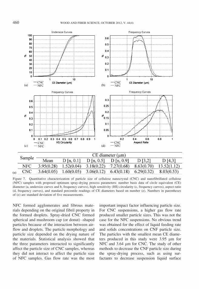
NFC formed agglomerates and fibrous mate-rials depending on the original fibril property inthe formed droplets. Spray-dried CNC formedspherical and mushroom cap (or donut) -shapedparticles because of the interaction between air-flow and droplets. The particle morphology andparticle size depended on the drying nature ofthe materials. Statistical analysis showed thatthe three parameters interacted to significantlyaffect the particle size of CNC samples, whereasthey did not interact to affect the particle sizeof NFC samples. Gas flow rate was the most
important impact factor influencing particle size.For CNC suspensions, a higher gas flow rateproduced smaller particle sizes. This was not thecase for the NFC suspensions. No obvious trendwas obtained for the effect of liquid feeding rateand solids concentrations on CNF particle size.The particles with the smallest mean CE diame-ters produced in this study were 3.95 mm forNFC and 3.64 mm for CNC. The study of othermethods to decrease the CNF particle size duringthe spray-drying process, such as using sur-factants to decrease suspension liquid surface
Figure 7. Quantitative characterization of particle size of cellulose nanocrystal (CNC) and nanofibrillated cellulose
(NFC) samples with proposed optimum spray-drying process parameters: number basis data of circle equivalent (CE)
diameter (a, undersize curves and b, frequency curves), high sensitivity (HS) circularity (c, frequency curves), aspect ratio
(d, frequency curves), and standard percentile readings of CE diameters based on number (e). Numbers in parentheses
of (e) are standard deviation of five measurements.
460 WOOD AND FIBER SCIENCE, OCTOBER 2012, V. 44(4)

tension and chemical modification to decreaseCNF surface energy, is ongoing.
ACKNOWLEDGMENTS
We acknowledge the US Army Corps of Engi-neers, Engineering R&D Center, and theMaine Agricultural and Forestry ExperimentStation McIntire-Stennis Project ME09615-06for financial support. The content and infor-mation does not necessarily reflect the positionof the funding agencies. Much appreciation goesto J. Rettenmaier & Sohne GMBH Companyfor donating the nanofibrillated cellulose andthe USDA Forest Service Forest Products Labo-ratory for donating the cellulose nanocrystals.This is paper 3278 of the Maine Agriculturaland Forest Experiment Station.
REFERENCES
Beecher JF (2007) Organic materials: Wood, trees and
nanotechnology. Nat Nanotechnol 2:466-467.
Brinker CJ, Scherer GW (1990) Drying. Pages 453-513 inCJ Brinker and GW Scherer, eds. Sol-gel science: The
physics and chemistry of sol-gel processing, 1st ed.
Academic Press Limited, London, UK.
Eichhorn SJ, Dufresne A, Aranguren M, Marcovich NE,
Capadona JR, Rowan SJ, Weder C, Thielemans W, Roman
M, Renneckar S, Gindl W, Veigel S, Keckes J, Yano H,
Abe K, Nogi M, Nakagaito AN, Mangalam A, Simonsen J,
Benight AS, Bismarck A, Berglund LA, Peijs T (2010)
Review: Current international research into cellulose
nanofibres and nanocomposites. J Mater Sci 45:1-33.
Farid M (2003) A new approach to modeling of single
droplet drying. Chem Eng Sci 58(13):2985-2993.
Gardner DJ, Oporto GS, Mills R, Samir MASA (2008)
Adhesion and surface issues in cellulose and nanocellulose.
J Adhes Sci Technol 22:545-567.
Habibi Y, Lucia LA, Rojas OJ (2010) Cellulose nano-
crystals: Chemistry, self-assembly, and applications. Chem
Rev 110:3479-3500.
Handscomb CS, Kraft M, Bayly AE (2009) A new model
for the drying of droplets containing suspended solids.
Chem Eng Sci 64:628-637.
Hede PD, Bach P, Jensen AD (2008) Two-fluid spray atom-
ization and pneumatic nozzles for fluid bed coating/
agglomeration purposes: A review. Chem Eng Sci 63:
3821-3842.
Hubbe MA, Rojas OJ, Lucia LA, Sain M (2008) Cellulosic
nanocomposites: A review. Bioresources 3(3):929-980.
Kim KY, Marshall WRJ (1971) Drop-size distributions
from pneumatic atomizers. AIChE J 17(3):575-584.
Klemm D, Kramer F, Moritz S, Lindstrom T, Ankerfors
M, Gray D, Dorris A (2011) Nanocelluloses: A new
family of nature-based materials. Angew Chem Int Ed
50:5438-5466.
Kumar R, Prasad KSL (1971) Studies on pneumatic atomi-
zation. Industrial and Engineering Chemistry Process
Design and Development 10(3):357-365.
Lane WR (1951) Shatter of drops in streams of air. Ind Eng
Chem 43:1312-1317.
Lefebvre AH (1989) Atomisation and sprays. Hemisphere
Publishing Corporation, Washington, DC.
Moczo J, Pukanszky B (2008) Polymer micro and nano-
composites: Structure, interactions, properties. J Ind Eng
Chem 14:535-563.
Moon RJ, Marini A, Nairn J, Simonsen J, Youngblood J
(2011) Cellulose nanomaterials review: Structure, prop-
erties and nanocomposites. Chem Soc Rev 40:3941-3994.
Mujumdar AS, Devahastin S (2000) Fundamental princi-
ples of drying. Pages 1-22 in S Devahastin, ed. Mujumdar’s
practical guide to industrial drying. Exergex Vorp.,
Montreal, Canada.
Nandiyanto ABD, Okuyama K (2011) Progress in devel-
oping spray-drying methods for the production of con-
trolled morphology particles: From the nanometer to
submicrometer size ranges. Advanced Powder Technology
22:1-19.
Nukiyama S, Tanasawa Y (1938) An experiment on the
atomization of liquids by means of an air stream. Trans
Soc Mech Engrs (Japan) 14(4):86-93.
Patel KC, Chen XD, Kar S (2005) The temperature uni-
formity during air drying of a colloidal liquid droplet.
Drying Technol 23:2337-2367.
Peng Y, Gardner DJ, Han Y (2012) Drying cellulose nano-
fibrils: In search of a suitable method. Cellulose 19(1):
91-102.
Rizkalla AA, Lefebvre AH (1975) The influence of air and
liquid properties on airblast atomization. J Fluid Eng-T
ASME 97(3):316-320.
Scherer GW (1990) Theory of drying. J Am Ceram Soc
73:3-14.
Schick RJ (2006) Spray technology reference guide: Under-
standing drop size. Spray Analysis and Research Services,
Spray Drying Systems Co. Wheaton, Illinois, USA. 35 pp.
Siqueira G, Bras J, Dufresne A (2010) Cellulosic bionano-
composites: A review of preparation, properties and
applications. Polymers 2:728-765.
Siro I, Plackett D (2010) Microfibrillated cellulose and
new nanocomposite materials: A review. Cellulose 17:
459-494.
Vehring R (2007) Pharmaceutical particle engineering via
spray drying. Pharm Res 25(5):999-1022.
Walton DE, Mumford CJ (1999) Spray dried products—
Characterization of particle morphology. Chem Eng Res
Des 77(1):21-38.
Peng et al—DRYING PROCESS EFFECTS ON CELLULOSE NANOFIBRILS 461


![Controlling Surface Charge Generated by Contact ... · A recent example involves functionalizing nitro or methyl groups in bulk cellulose nanofibrils.[18] Another method for controlling](https://static.fdocuments.in/doc/165x107/5e8418134552014a727a7028/controlling-surface-charge-generated-by-contact-a-recent-example-involves-functionalizing.jpg)