Universal Circuit Fabricator Conference Paper
8
Universal Circuit Fabricator Erolle Dayuta, Hector Melendez, Kyle Scott Dept. of Electrical Engineering and Computer Science, University of Central Florida, Orlando, Florida, 32816-2450 Abstract — The objective of this paper is to incorporate the design, methodology and process to create a two dimensional inkjet printer that uses conductive ink to create a functional circuit without the usage of breadboards or wires. Acknowledging the rise of three dimensional printing, the Universal Circuit Fabricator uses a combination of hardware and software design derived from three- dimensional printing software in order to make the process of circuit testing more accessible to students and engineers alike. Index Terms — AC-DC power converters, conductive ink, conductivity, inkjet, microcontroller, printed circuits, printing, I. INTRODUCTION When engineers need to prototype their circuits, they utilize a tool called a breadboard. Breadboards have been used for prototyping since the 1970’s. It’s a versatile tool that engineers use to prototype and experiment with their circuits without having to solder. Some of the biggest drawbacks of breadboards are cable organization, visual appeal, and their many troubleshooting challenges. The Universal Circuit Fabricator (UCF) aims to alleviate these problems allowing the user to bring circuit ideas to life more efficiently than with conventional breadboards. The idea behind this project is to take a circuit diagram, made with a circuit design program, and print the circuit traces onto an insulated surface with conductive ink. With this design, the user can place the corresponding components onto the printed traces so the circuit is ready for testing. The use of this device will not only apply to engineers in the field, but it will also help engineers who are still in college. Every engineer has to take classes that provide them with experiences to apply what they have learned. There, students build and design specific kinds of circuits, which are simulated in a circuit design program. After that is finished, the students then build the physical circuit which is done utilizing a breadboard. This is the motivation to create the Universal Circuit Fabricator. The UCF will allow the user to print their circuit schematic from serial input via USB with a computer. The Universal Circuit Fabricator is approximately the same size as conventional inkjet printers. This design makes it appropriate for prototyping purposes, as well as learning purposes. Future applications of printing conductive materials are limitless. For example, an inkjet cartridge filled with conductive ink could be an additional tool included on a 3D printer, allowing a designer to use additive manufacturing techniques to design and build a product with electronics embedded inside the housing while being manufactured. The concept of creating built in wiring inside of a 3D printed object would allow a designer to create a smaller and cheaper product. II. RESEARCH The Universal Circuit Fabricator relies on the concept of depositing a liquid conductive ink onto an insulating substrate via an HP C6602 inkjet print cartridge. Conductive ink technology is a developing field that has recently gained interest in the world of electrical engineering [1]-[2]. A. Conductive Ink While there are several commercially available conductive ink products that might meet the specifications of the UCF, they are expensive and proprietary. For the application of this project, several formulas for developing conductive ink were researched and considered for development and testing. B. Conductive Ink Design Requirements Conductive ink formulas were considered against the design requirements shown below in Table I to identify plausible choices. The optimal ink variety was selected by choosing the ink with the best performance to price ratio, keeping in mind the importance of low resistivity ( Ω∙m). Some of the conductive ink formulas require annealing to transform the ink into a finalized state. Annealing is the process of heating a material and allowing it to cool down slowly in an effort to fuse the material into a continuous structure, thus toughening it and reducing resistivity. TABLE I CONDUCTIVE INK DESIGN REQUIREMENTS The HP C6602 inkjet cartridge must be able to store the conductive ink without leaking. The HP C6602 inkjet cartridge print cartridge must be able to print a line of conductive ink without clogging. Electrical resistivity less than 1 × 10 −3 Ω∙ Solid finalized state
Transcript of Universal Circuit Fabricator Conference Paper
Universal Circuit Fabricator
Erolle Dayuta, Hector Melendez, Kyle Scott
Dept. of Electrical Engineering and Computer
Science, University of Central Florida, Orlando,
Florida, 32816-2450
Abstract — The objective of this paper is to incorporate
the design, methodology and process to create a two dimensional inkjet printer that uses conductive ink to create a functional circuit without the usage of breadboards or
wires. Acknowledging the rise of three dimensional printing, the Universal Circuit Fabricator uses a combination of hardware and software design derived from three-
dimensional printing software in order to make the process of circuit testing more accessible to students and engineers alike.
Index Terms — AC-DC power converters, conductive ink, conductivity, inkjet, microcontroller, printed circuits, printing,
I. INTRODUCTION
When engineers need to prototype their circuits, they
utilize a tool called a breadboard. Breadboards have been
used for prototyping since the 1970’s. It’s a versatile tool
that engineers use to prototype and experiment with their
circuits without having to solder. Some of the biggest
drawbacks of breadboards are cable organization, visual
appeal, and their many troubleshooting challenges.
The Universal Circuit Fabricator (UCF) aims to
alleviate these problems allowing the user to bring circuit
ideas to life more efficiently than with conventional
breadboards. The idea behind this project is to take a
circuit diagram, made with a circuit design program, and
print the circuit traces onto an insulated surface with
conductive ink. With this design, the user can place the
corresponding components onto the printed traces so the
circuit is ready for testing.
The use of this device will not only apply to engineers
in the field, but it will also help engineers who are still in
college. Every engineer has to take classes that provide
them with experiences to apply what they have learned.
There, students build and design specific kinds of circuits,
which are simulated in a circuit design program. After that
is finished, the students then build the physical circuit
which is done utilizing a breadboard. This is the
motivation to create the Universal Circuit Fabricator. The
UCF will allow the user to print their circuit schematic
from serial input via USB with a computer. The Universal
Circuit Fabricator is approximately the same size as
conventional inkjet printers. This design makes it
appropriate for prototyping purposes, as well as learning
purposes.
Future applications of printing conductive materials are
limitless. For example, an inkjet cartridge filled with
conductive ink could be an additional tool included on a
3D printer, allowing a designer to use additive
manufacturing techniques to design and build a product
with electronics embedded inside the housing while being
manufactured. The concept of creating built in wiring
inside of a 3D printed object would allow a designer to
create a smaller and cheaper product.
II. RESEARCH
The Universal Circuit Fabricator relies on the concept of
depositing a liquid conductive ink onto an insulating
substrate via an HP C6602 inkjet print cartridge.
Conductive ink technology is a developing field that has
recently gained interest in the world of electrical
engineering [1]-[2].
A. Conductive Ink
While there are several commercially available
conductive ink products that might meet the specifications
of the UCF, they are expensive and proprietary. For the
application of this project, several formulas for developing
conductive ink were researched and considered for
development and testing.
B. Conductive Ink Design Requirements
Conductive ink formulas were considered against the
design requirements shown below in Table I to identify
plausible choices. The optimal ink variety was selected by
choosing the ink with the best performance to price ratio,
keeping in mind the importance of low resistivity (Ω ∙ m).
Some of the conductive ink formulas require annealing to
transform the ink into a finalized state. Annealing is the
process of heating a material and allowing it to cool down
slowly in an effort to fuse the material into a continuous
structure, thus toughening it and reducing resistivity.
TABLE I
CONDUCTIVE INK DESIGN REQUIREMENTS
The HP C6602 inkjet cartridge must be able to store the conductive ink without leaking.
The HP C6602 inkjet cartridge print cartridge must be able to print a line of conductive ink without clogging.
Electrical resistivity less than 1 × 10⁻³ Ω ∙ 𝑚
Solid finalized state
C. Gallium-Indium Ink
The Gallium-Indium Conductive Ink is simple to
produce and yields a viscous liquid metal alloy that is free
of particulates. It is simple and inexpensive to produce,
but is expensive in material costs when producing small
amounts. The alloy is comprised of two elements: 75.5%
Gallium and 24.5% Indium. Gallium, which has a melting
temperature of 85.59°F (29.77°C) will melt in the palm of
your hand. Indium has a slightly higher melting
temperature of 313.9°F (156.6°C). When the metals are
combined in a beaker of deionized water and heated to
122°F (50°C) the Gallium is melted and fuses with the
indium. After stirring with a glass rod, the alloy is fully
homogenized. A syringe is used to remove the ink, which
is heavier than water, from the beaker [3].
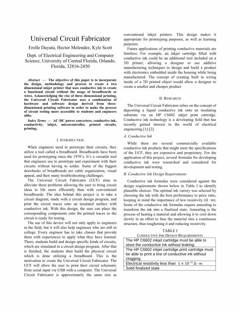
Upon testing the Gallium – Indium Conductive Ink, we
found that the alloy is highly electrically conductive as
seen below in Fig. 1. The Gallium – Indium Ink is liquid
at room temperature due to the chemical composition and
high concentration of Gallium. The viscosity of the ink
and its inability to cure to a solid finalized state makes this
ink formula incompatible with our design requirements.
Fig. 1. Test sample of Gallium-Indium conductive ink with a multimeter measuring electrical resistance of 2.6 Ω
D. Silver Acetate Ink
Silver Acetate Ink is produced using a chemical reaction
that yields elemental silver from a particulate free liquid.
It must be annealed to a substrate by heating, to form a
continuous trace with low resistivity that is solidified.
The Silver Acetate Ink is produced by combining 2.5mL
of Ammonium Hydroxide with 1 gram of Silver Acetate
in a beaker and mixed using a magnetic stir bar. Once the
Ammonium Hydroxide and Silver Acetate are fully
mixed, 0.2mL of Formic Acid is added to the solution one
drop at a time using a needle syringe while the magnetic
stir bar continues to mix the chemicals. The ink is left to
settle for 12 hours in an air tight container, allowing larger
silver particles settle at the bottom.
Using a 0.2µm syringe filter, the larger silver particles
are filtered from the solution. Once filtered, the ink is a
clear particulate free liquid. The ink is then stored in an air
tight container to prevent premature reaction of the ink.
When the Silver Acetate ink is exposed to air, the
Ammonium Hydroxide evaporates from the ink. The
Silver Acetate and Formic Acid are left behind to react
with each other. This reaction forms electrically
conductive elemental silver particles.
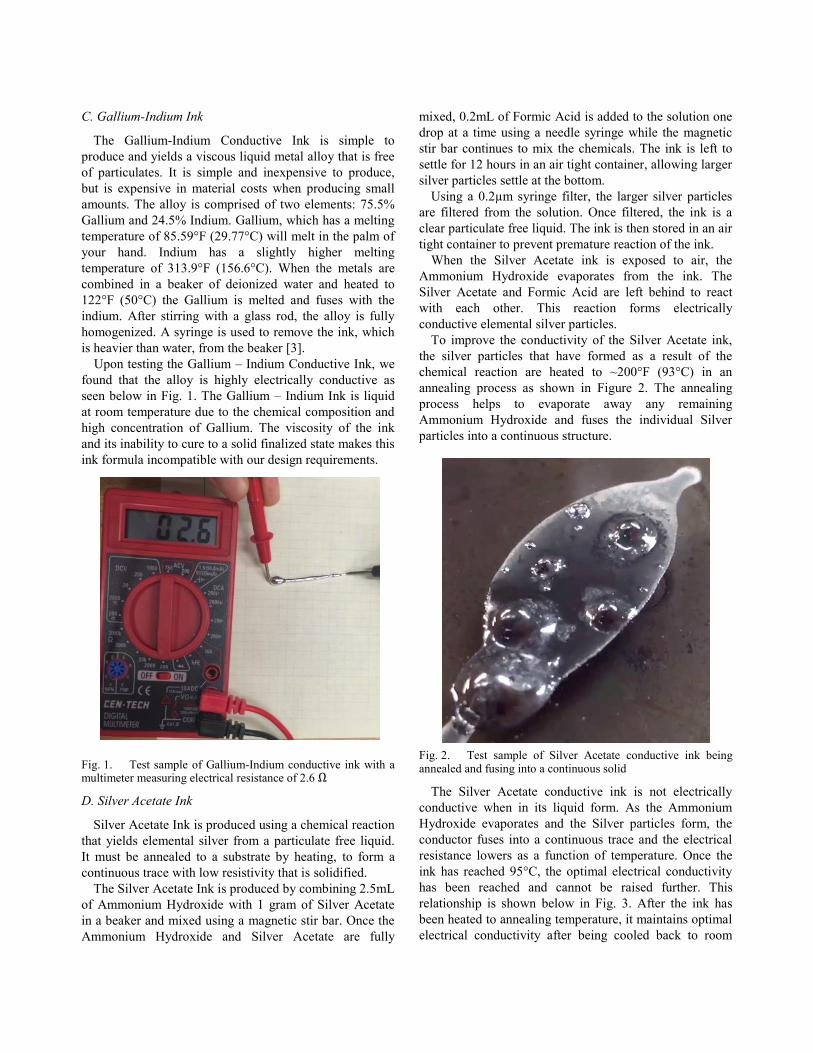
To improve the conductivity of the Silver Acetate ink,
the silver particles that have formed as a result of the
chemical reaction are heated to ~200°F (93°C) in an
annealing process as shown in Figure 2. The annealing
process helps to evaporate away any remaining
Ammonium Hydroxide and fuses the individual Silver
particles into a continuous structure.
Fig. 2. Test sample of Silver Acetate conductive ink being annealed and fusing into a continuous solid
The Silver Acetate conductive ink is not electrically
conductive when in its liquid form. As the Ammonium
Hydroxide evaporates and the Silver particles form, the
conductor fuses into a continuous trace and the electrical
resistance lowers as a function of temperature. Once the
ink has reached 95°C, the optimal electrical conductivity
has been reached and cannot be raised further. This
relationship is shown below in Fig. 3. After the ink has
been heated to annealing temperature, it maintains optimal
electrical conductivity after being cooled back to room
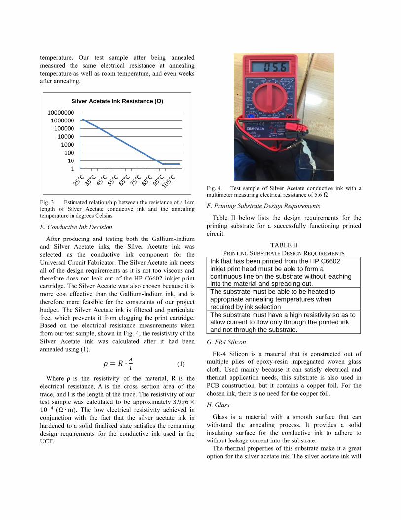
temperature. Our test sample after being annealed
measured the same electrical resistance at annealing
temperature as well as room temperature, and even weeks
after annealing.
Fig. 3. Estimated relationship between the resistance of a 1cm length of Silver Acetate conductive ink and the annealing temperature in degrees Celsius
E. Conductive Ink Decision
After producing and testing both the Gallium-Indium
and Silver Acetate inks, the Silver Acetate ink was
selected as the conductive ink component for the
Universal Circuit Fabricator. The Silver Acetate ink meets
all of the design requirements as it is not too viscous and
therefore does not leak out of the HP C6602 inkjet print
cartridge. The Silver Acetate was also chosen because it is
more cost effective than the Gallium-Indium ink, and is
therefore more feasible for the constraints of our project
budget. The Silver Acetate ink is filtered and particulate
free, which prevents it from clogging the print cartridge.
Based on the electrical resistance measurements taken
from our test sample, shown in Fig. 4, the resistivity of the
Silver Acetate ink was calculated after it had been
annealed using (1).
𝜌 = 𝑅 ∙𝐴
𝑙 (1)
Where ρ is the resistivity of the material, R is the
electrical resistance, A is the cross section area of the
trace, and l is the length of the trace. The resistivity of our
test sample was calculated to be approximately 3.996 ×10⁻⁴ (Ω ∙ m). The low electrical resistivity achieved in
conjunction with the fact that the silver acetate ink in
hardened to a solid finalized state satisfies the remaining
design requirements for the conductive ink used in the
UCF.
Fig. 4. Test sample of Silver Acetate conductive ink with a multimeter measuring electrical resistance of 5.6 Ω
F. Printing Substrate Design Requirements
Table II below lists the design requirements for the
printing substrate for a successfully functioning printed
circuit.
TABLE II
PRINTING SUBSTRATE DESIGN REQUIREMENTS
Ink that has been printed from the HP C6602 inkjet print head must be able to form a continuous line on the substrate without leaching into the material and spreading out.
The substrate must be able to be heated to appropriate annealing temperatures when required by ink selection
The substrate must have a high resistivity so as to allow current to flow only through the printed ink and not through the substrate.
G. FR4 Silicon
FR-4 Silicon is a material that is constructed out of
multiple plies of epoxy-resin impregnated woven glass
cloth. Used mainly because it can satisfy electrical and
thermal application needs, this substrate is also used in
PCB construction, but it contains a copper foil. For the
chosen ink, there is no need for the copper foil.
H. Glass
Glass is a material with a smooth surface that can
withstand the annealing process. It provides a solid
insulating surface for the conductive ink to adhere to
without leakage current into the substrate.
The thermal properties of this substrate make it a great
option for the silver acetate ink. The silver acetate ink will
110
1001000
10000100000
100000010000000
Silver Acetate Ink Resistance (Ω)

need to go through the annealing process; therefore the
substrate needs to withstand at least 200 degrees F.
I. Printing Substrate Decision
Based on the research, the substrate selection chosen
was glass. Glass is a good insulator that will minimize
leakage current between conductive traces. It is strong and
able to withstand the heating associated with the annealing
process of the Silver Acetate Ink. Glass is rigid and
inflexible which will reduce the risk of cracking the
conductive ink traces, once printed. In addition to the
electrical and material property benefits, glass is
transparent, which aids in the ability to read the layout of
printed circuit traces.
III. SYSTEM COMPONENTS
The Universal Circuit Fabricator features a steady
balance of hardware and software to achieve its purpose.
Each component is an integral part of the UCF design and
is described in detail in the following sections.
A. InkShield
The InkShield, designed by Nicholas C. Lewis [4]
allows you to connect an HP C6602 inkjet cartridge to a
microcontroller. The InkShield allows the user to control
all twelve nozzles within the inkjet cartridge, for better
printing accuracy. It uses pulse width modulation to
control the rate at which the nozzles release the ink. There
is also a power booster on the InkShield that increases the
12VDC input voltage to 20VDC to power the ink
cartridge.
B. Motor Control System
The Motor Control System is responsible for controlling
the movement of the X and Y axis stepper motors to
translate the print head across the print bed surface. It will
rely on data fed from the microprocessor as an input to
toggle the direction of the motor’s movements and the
amount of steps according to the circuit trace design. It
was chosen to operate the axes independent from each
other, in order to create a more accurate circuit trace.
C. Microcontroller
The microcontroller is a combination of the
microprocessor and the motor control system, featuring
the ATmega328P. The specifications are listed below on
Table III. The microcontroller features a USB connector,
in order to connect to a computer through an RS232 serial
connection. The microcontroller also uses headers that
allow it to interface directly with the InkShield. Also, the
microcontroller has additional headers in place, in case
additional features are added. The microcontroller can be
powered by two options, either the USB connection with
the computer that supplies 5VDC, or a barrel jack
connection that supplies 12VDC.
TABLE III
ATMEGA328P SPECIFICATIONS
Clock Speed 16 MHz
Voltage 7-12 V
EEPROM 1 KB
SRAM 2 KB
D. Power Supply
The power supply features a 120VAC/15VAC
transformer, an AC/DC full wave bridge rectifier, a large
capacitor to smooth ripple voltage, and two linear voltage
regulators. The first linear voltage regulator is the
LM7805 which reduces the input voltage to 5VDC to
power the motors and hardware switches. The second
linear voltage regulator is the LM7812 which reduces the
input voltage to 12VDC to power the InkShield
subsystem. Both linear voltage regulators are limited to
2.5A each. Fig. 5 below displays a schematic of the power
supply that was generated using the Multisim 12.0 circuit
simulation suite.
Fig. 5. Multisim schematic simulation of the Universal Circuit Fabricator power supply
IV. SYSTEM OVERVIEW
To represent a general overview of the Universal Circuit
Fabricator, software and hardware system representations
in the form of block diagrams were created. The block
diagrams serve to provide a top level view on how each
part of the system interacts. The following sections cover
both the hardware and software system overviews.

A. Hardware
Each block in the hardware block diagram on Fig. 6
below represents an important system component. The
figure also visualizes what systems are implemented in the
PCB and how it will integrate with external hardware.
Fig. 6. Universal Circuit Fabricator Hardware Block Diagram
B. Software
The software block diagram gives the complete
overview for all the software interactions in regards to the
Universal Circuit Fabricator. As seen in Fig. 7 below, the
microcontroller code is the main software system, which
receives user input data from the external PC, then goes
through a data conversion and processing system, then
into control software for each individual subsystem.
Finally, as the code moves out of the microcontroller, it
is converted into basic firmware code for each subsystem
in order to either move the motors or spray from the ink
nozzles.
Fig. 7. Universal Circuit Fabricator Software Block Diagram
V. HARDWARE DETAIL
The following section focuses on the primary hardware
systems both purchased and designed for the Universal
Circuit Fabricator. These components represent
components like the InkShield, the motor control drivers,
and finally, the ATMega328P microcontroller integrated
circuit within its own custom designed printed circuit
board (PCB).
A. InkShield
The InkShield is responsible for controlling the flow of
conductive ink from the HP C6602 inkjet cartridge. The
HP C6602 has a 96dpi resolution with 12 inkjet nozzles.
The InkShield drives the inkjet cartridge by supplying
20V to the HP C6602 via boost converter. The InkShield
also has a 4 to 16 multiplexer that allows the
microprocessor to only utilize four analog pins to control
the 12 nozzles on the inkjet. This gives the user the
possibility to trigger the nozzles in any possible
configuration. The InkShield utilizes pulse width
modulation to control the trigger mechanism of the inkjet
cartridge. The HP C6602 works by utilizing a PWM with
the following iterations: 5µs ON and 800µs OFF. This is
used because if there is no delay in between pulses, the
InkShield will overheat the nozzles, therefore making
them nonfunctional. In order to use this feature, the
InkShield uses one digital pin from the microprocessor,
which translates to using a total of five pins. Fig. 8 below
is a picture of the assembled InkShield inkjet control
system.
Fig. 8. Assembled InkShield circuit board
B. Motor Control System
The Motor Control system features a PWM Driver, and
two TB6612FNG DC motor drivers. The PWM Driver
allows us to only utilize two analog pins from the
microprocessor. The advantage of utilizing the
TB6612FNG motor driver is that it creates lower voltage
drops across the motors to increase torque and accuracy.
Motor Control
System
TI MSP430
Microprocessor
User Input
USB Interface
Inkjet Control
System
HP C6602 Ink
CartridgeX-Axis Motor
X-Axis Motor
Custom PCB containing
embedded subsystems
Microcontroller Code
(Universal Circuit Fabricator)
User Input
Data
Retrieval
Data
Conversion
and
Processing
Subsystem
Control
Software
Individual
Subsystem
Firmware
Code

The motor driver chip contains 2 H-Bridges, which allows
the UCF to utilize bidirectional motors. The H-Bridge
motor drivers will control two NEMA 17 stepper motors
for the X and Y axes. The use of only two analog pins
makes the use of this PWM driver essential in the design
of the Universal Circuit Fabricator.
C. Microcontroller
Discussed earlier, the Universal Circuit Fabricator uses
a customized version of an Arduino UNO development
board with an ATMega328P 8-bit AVR RISC-based
microcontroller. Within the design, only the components
that were necessary for the design functionality of the
UCF were used in the final PCB. The main use of the
ATMega328P was to interface the input circuit design
from the external PC with the primary components of the
UCF, such as the InkShield and the motor control system.
Other functions needed were the USB and UART
communications to communicate with the external PC, as
well as the digital I/O pins in order to interface the
ATMega328P with the motor control driver chips used to
move the stepper motors.
D. Printed Circuit Board Design
CADSOFT Eagle was utilized in order to create the
custom printed circuit board (PCB) design for the
Universal Circuit Fabricator. The PCB houses all the
subsystems of the UCF, as well as the ATMega328P
microcontroller. The PCB design contains a USB input for
both power and communication between the external PC
and the UCF, powered by the ATMEGA16U2 chip which
acts as a serial to USB converter. It also contains two
TB6612FNG motor control drivers which power the two
stepper motors. Finally, it includes a series of headers
from the I/O pins of the ATMega328P that interfaces
directly with the InkShield in order to provide seamless
integration.
The primary design considerations were simplicity to
control costs, as well as functionality within the original
design. For those reasons, it was decided that the primary
power supply of the system would remain off the board in
order to reduce troubleshooting. The PCB manufacturer
chosen for the UCF was OshPark as it provided great
service for a reasonable price, as well as providing three
copies of the printed circuit board in case an error in
assembly occurred. The PCB board layout is presented
below in Fig. 9 and the printed physical PCB in Fig. 10
Fig. 9. Universal Circuit Fabricator Custom Printed Circuit
Board layout
Fig. 10. Universal Circuit Fabricator Custom Printed Circuit
Board

VI. SOFTWARE DETAIL
The software of the Universal Circuit Fabricator
interacts with the user via serial communication over USB
with an external computer. The software is designed to
allow the user to create, on an external computer, a text
file (.txt) that contains G-Code commands which describe
the design to be printed. The user then opens
GcodeSender, a java based serial communication
graphical user interface, on an external computer to
connect to the USB COM port that the Universal Circuit
Fabricator is interfaced with. Once the UCF has been
successfully connected, the main menu is displayed in the
graphical user interface of GCodeSender. This allows the
user to type and send individual lines of GCode at a time.
GCodeSender also allows the user to select a .txt file from
the hard drive of the computer. Once selected, the text file
is sent to the UCF one line at a time until every command
has been performed.
A. Subsystem Software
The InkShield code utilizes a set of libraries that are
compatible with the ATMega328P. These libraries are
small in size which allows the user to use the memory
within the microprocessor with more flexibility. There are
a few commands incorporated in the libraries that allow
the user to set the configuration of the nozzles that will be
used during the printing process. Those commands were
made into functions that can be called within the overall
code for the UCF. The functions give us the flexibility to
create a more elaborate code.
The Motor Control System code utilizes four possible
ways to drive the motors: single steps, double steps, micro
steps, and interleave. The UCF uses the interleave setting
for all of the motor commands. The motor code takes the
commands from the G-Code text file and depending on
the type of command, will operate the respective stepper
motor. There are several motor command functions that
make the InkShield Code and motor commands run
simultaneously.
B. G-Code
G-Code is a common programming language used in the
CNC and 3D printing industries. It is a vector based motor
control algorithm that uses a Cartesian coordinate system
to define present location of the tool in use and standard
increments to precisely control movement in the X, Y, and
Z directions. In the software configuration of the UCF,
only a select number of G-code commands are necessary.
For example, Z axis control, alternate tool selection, and
circular movement are not required for printing two
dimensional lines for circuit traces.
Prior to a design being printed, the UCF requires that a
homing sequence be completed so that the print nozzle is
moved into the origin of the coordinate axis. The homing
sequence is initiated by sending “G28;” through the COM
port. The UCF then moves the X motor in the reverse
direction until a hardware switch mounted on the frame is
pressed, signaling that the carriage has been moved to the
origin of the X axis. Similarly, the Y axis origin is found
using a hardware switch mounted on the frame. Once the
homing sequence is completed the UCF is ready to print a
design.
Table IV lists all commands that the UCF has been
programmed to execute. These commands are sent to the
GcodeSender graphical user interface upon startup of the
UCF to tell the user what commands it is able to complete.
TABLE IV
UCF G-CODE COMMANDS
G00 [X(steps)] [Y(steps)] [F(feedrate)]
linear move – no ink
G01 [X(steps)] [Y(steps)] [F(feedrate)]
linear move – spray ink
G04 P[seconds] - delay
G28 move to Home-Position/Origin
G90 absolute mode
G91 relative mode
G92 [X(steps)] [Y(steps)] - change logical
position
M18 release motors
M100 this help message
M114 report position and feedrate
Multiple lines of G-Code commands can be completed
sequentially when saved in a .txt file and sent using the
GCodeSender graphical user interface. For example the
commands listed below in Fig. 11 result in the printing of
a star in Fig. 12.
G28;
G00 X7.523 Y6.275 F130;
G01 X4.865 Y4.451 F130;
G01 X5.776 Y7.544 F130;
G01 X3.221 Y9.509 F130;
G01 X6.444 Y9.598 F130;
G01 X7.523 Y12.635 F130;
G01 X8.603 Y9.596 F130;
G01 X11.825 Y9.509 F130;
G01 X9.270 Y7.544 F130;
G01 X10.183 Y4.452 F130;
G01 X10.182 Y4.451 F130;
G01 X10.181 Y4.451 F130;
G01 X7.523 Y6.275 F130;
Fig. 11. G-Code commands for printing a star
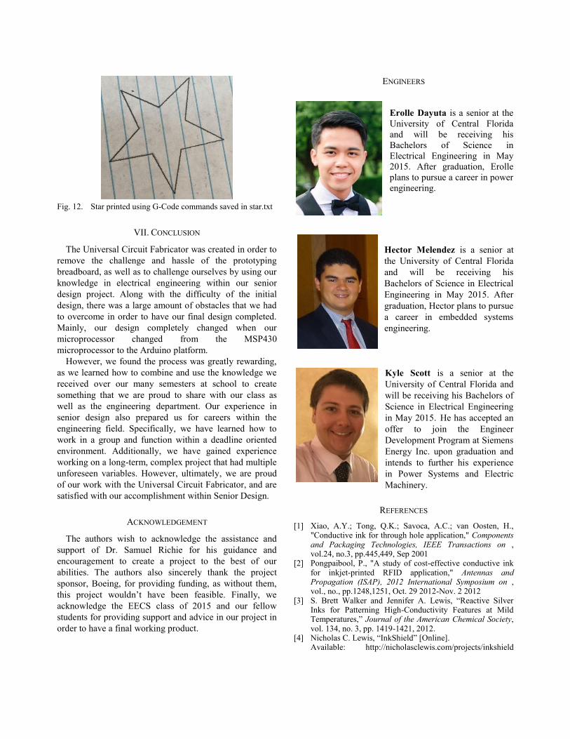
Fig. 12. Star printed using G-Code commands saved in star.txt
VII. CONCLUSION
The Universal Circuit Fabricator was created in order to
remove the challenge and hassle of the prototyping
breadboard, as well as to challenge ourselves by using our
knowledge in electrical engineering within our senior
design project. Along with the difficulty of the initial
design, there was a large amount of obstacles that we had
to overcome in order to have our final design completed.
Mainly, our design completely changed when our
microprocessor changed from the MSP430
microprocessor to the Arduino platform.
However, we found the process was greatly rewarding,
as we learned how to combine and use the knowledge we
received over our many semesters at school to create
something that we are proud to share with our class as
well as the engineering department. Our experience in
senior design also prepared us for careers within the
engineering field. Specifically, we have learned how to
work in a group and function within a deadline oriented
environment. Additionally, we have gained experience
working on a long-term, complex project that had multiple
unforeseen variables. However, ultimately, we are proud
of our work with the Universal Circuit Fabricator, and are
satisfied with our accomplishment within Senior Design.
ACKNOWLEDGEMENT
The authors wish to acknowledge the assistance and
support of Dr. Samuel Richie for his guidance and
encouragement to create a project to the best of our
abilities. The authors also sincerely thank the project
sponsor, Boeing, for providing funding, as without them,
this project wouldn’t have been feasible. Finally, we
acknowledge the EECS class of 2015 and our fellow
students for providing support and advice in our project in
order to have a final working product.
ENGINEERS
Erolle Dayuta is a senior at the
University of Central Florida
and will be receiving his
Bachelors of Science in
Electrical Engineering in May
2015. After graduation, Erolle
plans to pursue a career in power
engineering.
Hector Melendez is a senior at
the University of Central Florida
and will be receiving his
Bachelors of Science in Electrical
Engineering in May 2015. After
graduation, Hector plans to pursue
a career in embedded systems
engineering.
Kyle Scott is a senior at the
University of Central Florida and
will be receiving his Bachelors of
Science in Electrical Engineering
in May 2015. He has accepted an
offer to join the Engineer
Development Program at Siemens
Energy Inc. upon graduation and
intends to further his experience
in Power Systems and Electric
Machinery.
REFERENCES
[1] Xiao, A.Y.; Tong, Q.K.; Savoca, A.C.; van Oosten, H., "Conductive ink for through hole application," Components and Packaging Technologies, IEEE Transactions on , vol.24, no.3, pp.445,449, Sep 2001
[2] Pongpaibool, P., "A study of cost-effective conductive ink for inkjet-printed RFID application," Antennas and Propagation (ISAP), 2012 International Symposium on , vol., no., pp.1248,1251, Oct. 29 2012-Nov. 2 2012
[3] S. Brett Walker and Jennifer A. Lewis, “Reactive Silver Inks for Patterning High-Conductivity Features at Mild Temperatures,” Journal of the American Chemical Society, vol. 134, no. 3, pp. 1419-1421, 2012.
[4] Nicholas C. Lewis, “InkShield” [Online]. Available: http://nicholasclewis.com/projects/inkshield