UNIT-I Principles of Electromechanical Energy...
15
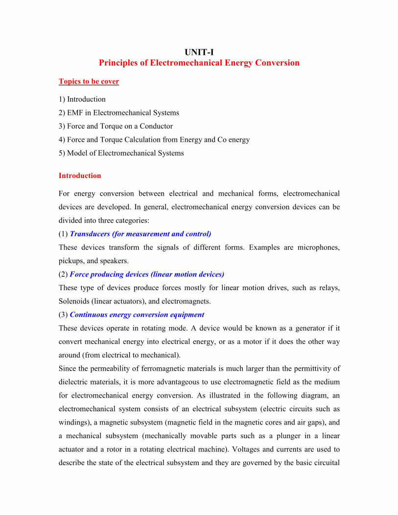
UNIT-I Principles of Electromechanical Energy Conversion Topics to be cover 1) Introduction 2) EMF in Electromechanical Systems 3) Force and Torque on a Conductor 4) Force and Torque Calculation from Energy and Co energy 5) Model of Electromechanical Systems Introduction For energy conversion between electrical and mechanical forms, electromechanical devices are developed. In general, electromechanical energy conversion devices can be divided into three categories: (1) Transducers (for measurement and control) These devices transform the signals of different forms. Examples are microphones, pickups, and speakers. (2) Force producing devices (linear motion devices) These type of devices produce forces mostly for linear motion drives, such as relays, Solenoids (linear actuators), and electromagnets. (3) Continuous energy conversion equipment These devices operate in rotating mode. A device would be known as a generator if it convert mechanical energy into electrical energy, or as a motor if it does the other way around (from electrical to mechanical). Since the permeability of ferromagnetic materials is much larger than the permittivity of dielectric materials, it is more advantageous to use electromagnetic field as the medium for electromechanical energy conversion. As illustrated in the following diagram, an electromechanical system consists of an electrical subsystem (electric circuits such as windings), a magnetic subsystem (magnetic field in the magnetic cores and air gaps), and a mechanical subsystem (mechanically movable parts such as a plunger in a linear actuator and a rotor in a rotating electrical machine). Voltages and currents are used to describe the state of the electrical subsystem and they are governed by the basic circuital
Transcript of UNIT-I Principles of Electromechanical Energy...
UNIT-I
Principles of Electromechanical Energy Conversion
Topics to be cover
1) Introduction
2) EMF in Electromechanical Systems
3) Force and Torque on a Conductor
4) Force and Torque Calculation from Energy and Co energy
5) Model of Electromechanical Systems
Introduction
For energy conversion between electrical and mechanical forms, electromechanical
devices are developed. In general, electromechanical energy conversion devices can be
divided into three categories:
(1) Transducers (for measurement and control)
These devices transform the signals of different forms. Examples are microphones,
pickups, and speakers.
(2) Force producing devices (linear motion devices)
These type of devices produce forces mostly for linear motion drives, such as relays,
Solenoids (linear actuators), and electromagnets.
(3) Continuous energy conversion equipment
These devices operate in rotating mode. A device would be known as a generator if it
convert mechanical energy into electrical energy, or as a motor if it does the other way
around (from electrical to mechanical).
Since the permeability of ferromagnetic materials is much larger than the permittivity of
dielectric materials, it is more advantageous to use electromagnetic field as the medium
for electromechanical energy conversion. As illustrated in the following diagram, an
electromechanical system consists of an electrical subsystem (electric circuits such as
windings), a magnetic subsystem (magnetic field in the magnetic cores and air gaps), and
a mechanical subsystem (mechanically movable parts such as a plunger in a linear
actuator and a rotor in a rotating electrical machine). Voltages and currents are used to
describe the state of the electrical subsystem and they are governed by the basic circuital

laws: Ohm's law, KCL and KVL. The state of the mechanical subsystem can be described
in terms of positions, velocities, and accelerations, and is governed by the Newton's laws.
The magnetic subsystem or magnetic field fits between the electrical and mechanical
subsystems and acting as a "ferry" in energy transform and conversion. The field
quantities such as magnetic flux, flux density, and field strength, are governed by the
Maxwell's equations. When coupled with an electric circuit, the magnetic flux interacting
with the current in the circuit would produce a force or torque on a mechanically movable
part. On the other hand, the movement of the moving part will could variation of the
magnetic flux linking the electric circuit and induces an electromotive force (emf) in the
circuit. The product of the torque and speed (the mechanical power) equals the active
component of the product of the emf and current. Therefore, the electrical energy and the
mechanical energy are inter converted via the magnetic field.
In this chapter, the methods for determining the induced emf in an electrical circuit and
force/torque experienced by a movable part will be discussed. The general concept of
electromechanical system modeling will also be illustrated by a singly excited rotating
system.
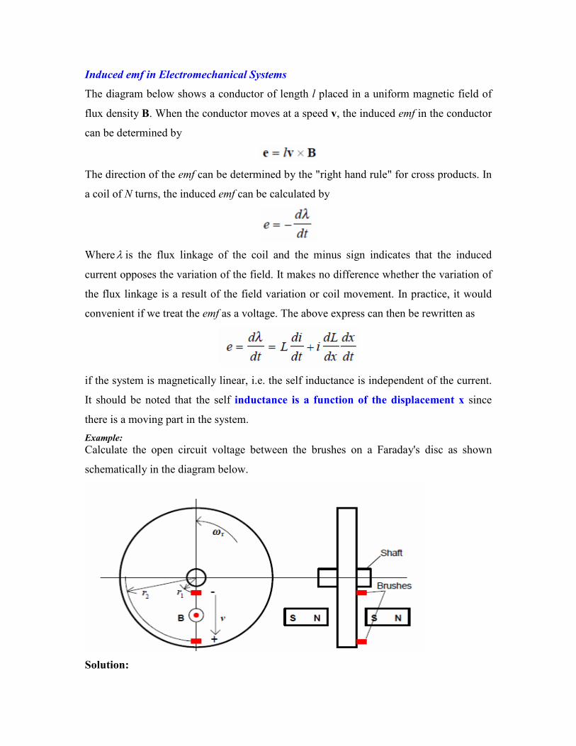
Induced emf in Electromechanical Systems
The diagram below shows a conductor of length l placed in a uniform magnetic field of
flux density B. When the conductor moves at a speed v, the induced emf in the conductor
can be determined by
The direction of the emf can be determined by the "right hand rule" for cross products. In
a coil of N turns, the induced emf can be calculated by
Whereλ is the flux linkage of the coil and the minus sign indicates that the induced
current opposes the variation of the field. It makes no difference whether the variation of
the flux linkage is a result of the field variation or coil movement. In practice, it would
convenient if we treat the emf as a voltage. The above express can then be rewritten as
if the system is magnetically linear, i.e. the self inductance is independent of the current.
It should be noted that the self inductance is a function of the displacement x since
there is a moving part in the system.
Example:
Calculate the open circuit voltage between the brushes on a Faraday's disc as shown
schematically in the diagram below.
Solution:
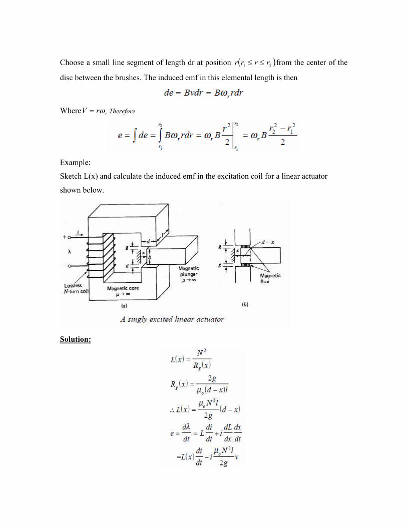
Choose a small line segment of length dr at position ( )21 rrrr ≤≤ from the center of the
disc between the brushes. The induced emf in this elemental length is then
Where rrV ω= Therefore
Example:
Sketch L(x) and calculate the induced emf in the excitation coil for a linear actuator
shown below.
Solution:

Force and Torque on a Current Carrying Conductor:
The force on a moving particle of electric charge q in a magnetic field is given by the
Lorentz's force law:
The force acting on a current carrying conductor can be directly derived from the
equation as
where C is the contour of the conductor. For a homogeneous conductor of length l
carrying current I in a uniform magnetic field, the above expression can be reduced to
In a rotating system, the torque about an axis can be calculated by
Where r is the radius vector from the axis towards the conductor
Force and Torque Calculation from Energy and Co energy:
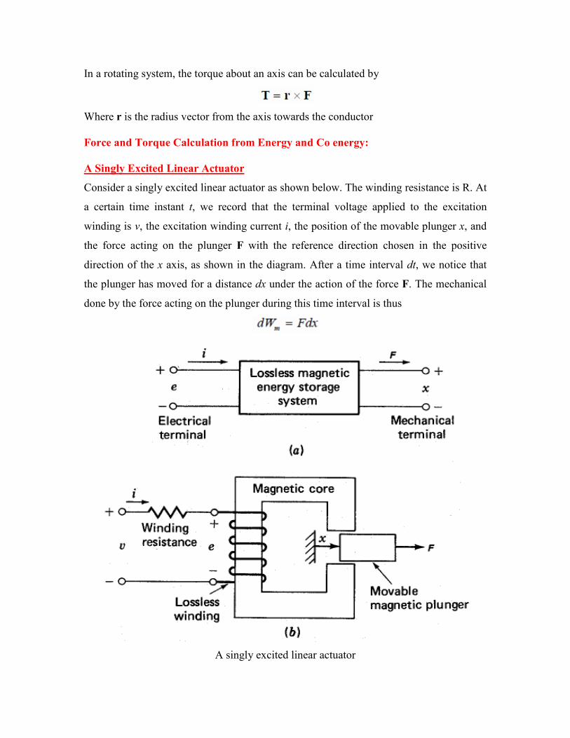
A Singly Excited Linear Actuator
Consider a singly excited linear actuator as shown below. The winding resistance is R. At
a certain time instant t, we record that the terminal voltage applied to the excitation
winding is v, the excitation winding current i, the position of the movable plunger x, and
the force acting on the plunger F with the reference direction chosen in the positive
direction of the x axis, as shown in the diagram. After a time interval dt, we notice that
the plunger has moved for a distance dx under the action of the force F. The mechanical
done by the force acting on the plunger during this time interval is thus
A singly excited linear actuator
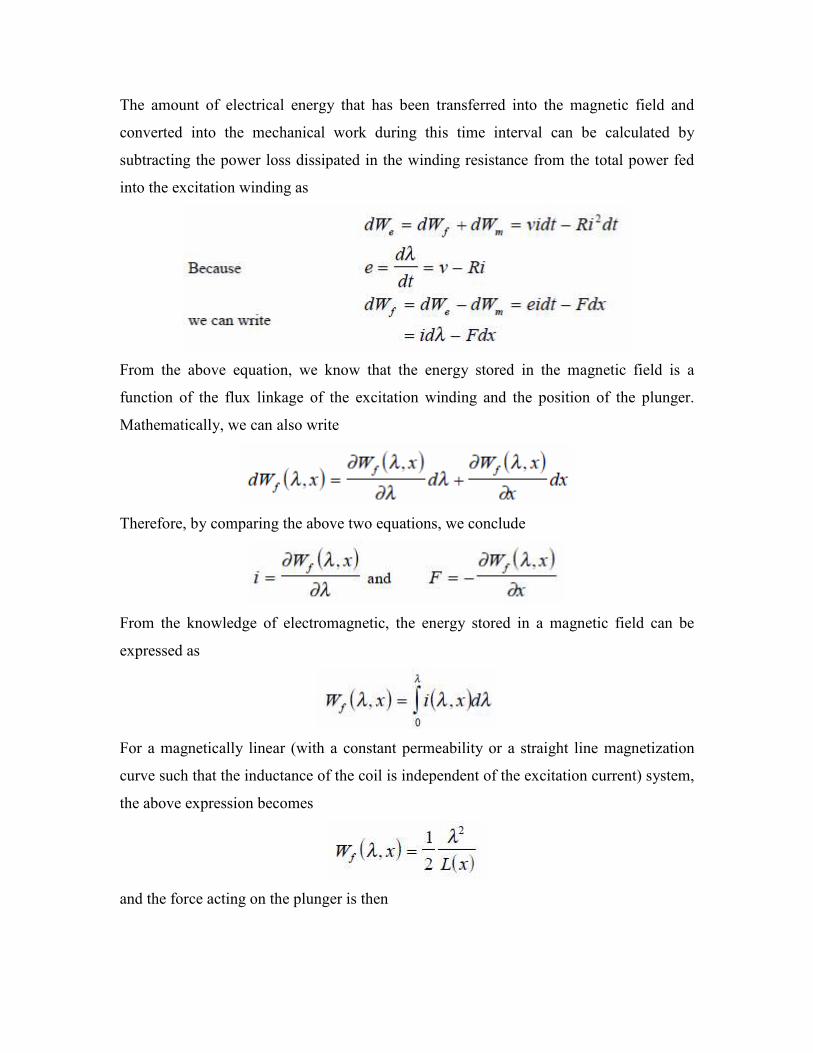
The amount of electrical energy that has been transferred into the magnetic field and
converted into the mechanical work during this time interval can be calculated by
subtracting the power loss dissipated in the winding resistance from the total power fed
into the excitation winding as
From the above equation, we know that the energy stored in the magnetic field is a
function of the flux linkage of the excitation winding and the position of the plunger.
Mathematically, we can also write
Therefore, by comparing the above two equations, we conclude
From the knowledge of electromagnetic, the energy stored in a magnetic field can be
expressed as
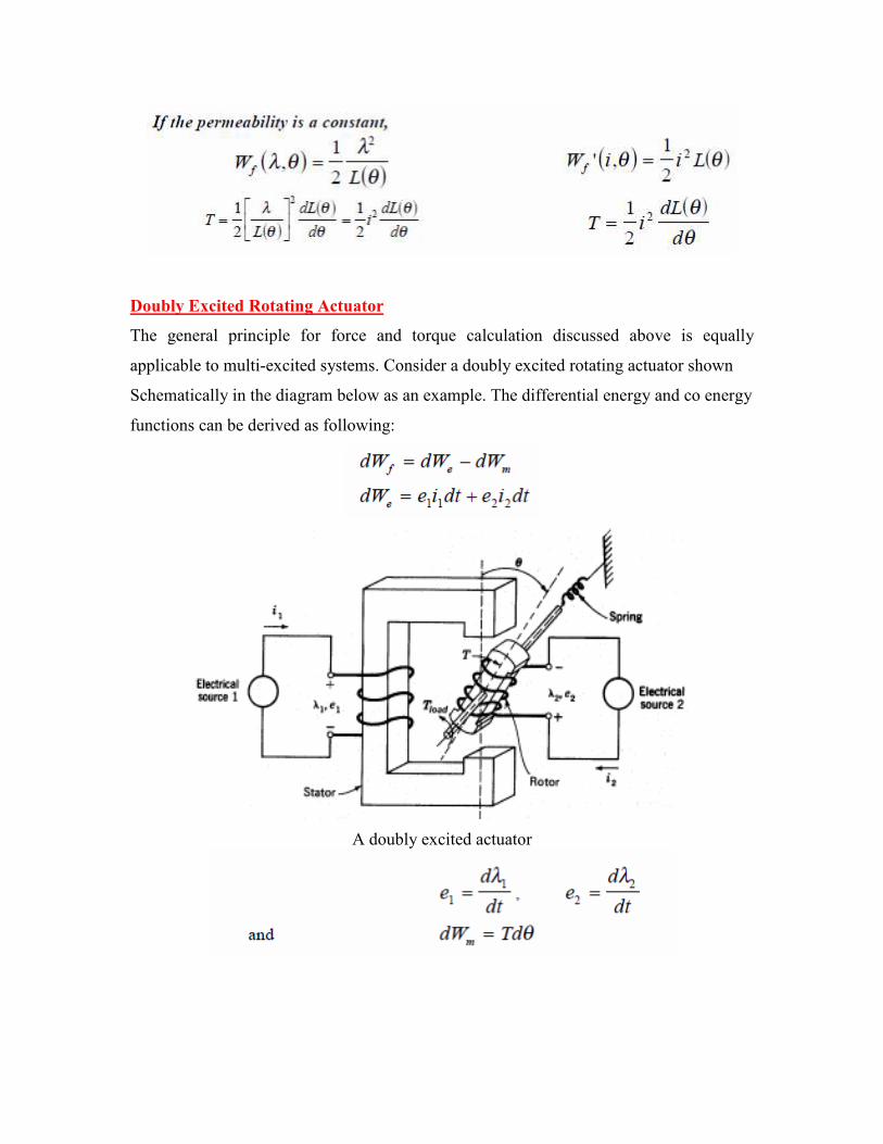
For a magnetically linear (with a constant permeability or a straight line magnetization
curve such that the inductance of the coil is independent of the excitation current) system,
the above expression becomes
and the force acting on the plunger is then
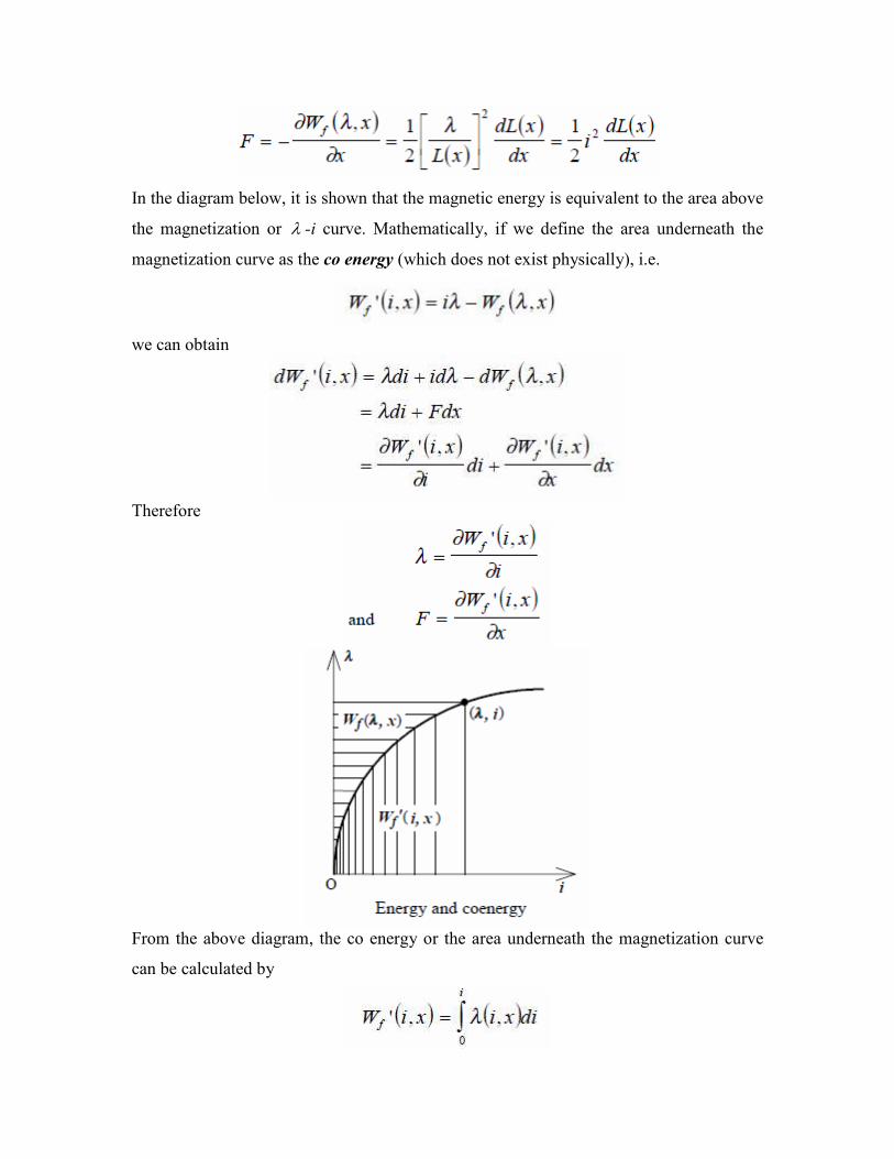
In the diagram below, it is shown that the magnetic energy is equivalent to the area above
the magnetization or λ -i curve. Mathematically, if we define the area underneath the
magnetization curve as the co energy (which does not exist physically), i.e.
we can obtain
Therefore
From the above diagram, the co energy or the area underneath the magnetization curve
can be calculated by

For a magnetically linear system, the above expression becomes
and the force acting on the plunger is then
Example:
Calculate the force acting on the plunger of a linear actuator discussed in this section.
Solution:
Assume the permeability of the magnetic core of the actuator is infinite, and hence the
system can be treated as magnetically linear. From the equivalent magnetic circuit of the
actuator shown in figure (c) above, one can readily find the self inductance of the
excitation winding as
Therefore, the force acting on the plunger is
The minus sign of the force indicates that the direction of the force is to reduce the
displacement so as to reduce the reluctance of the air gaps. Since this force is caused by
the variation of magnetic reluctance of the magnetic circuit, it is known as the reluctance
force.
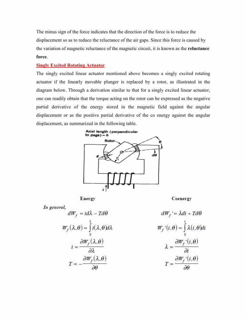
Singly Excited Rotating Actuator
The singly excited linear actuator mentioned above becomes a singly excited rotating
actuator if the linearly movable plunger is replaced by a rotor, as illustrated in the
diagram below. Through a derivation similar to that for a singly excited linear actuator,
one can readily obtain that the torque acting on the rotor can be expressed as the negative
partial derivative of the energy stored in the magnetic field against the angular
displacement or as the positive partial derivative of the co energy against the angular
displacement, as summarized in the following table.
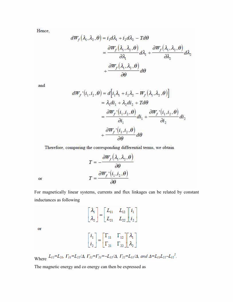
Doubly Excited Rotating Actuator
The general principle for force and torque calculation discussed above is equally
applicable to multi-excited systems. Consider a doubly excited rotating actuator shown
Schematically in the diagram below as an example. The differential energy and co energy
functions can be derived as following:
A doubly excited actuator
For magnetically linear systems, currents and flux linkages can be related by constant
inductances as following
Where
The magnetic energy and co energy can then be expressed as
Respectively, and it can be shown that they are equal.
Therefore, the torque acting on the rotor can be calculated as
Because of the salient (not round) structure of the rotor, the self inductance of the stator is
a function of the rotor position and the first term on the right hand side of the above
torque expression is nonzero for that 011 ≠θd
dL. Similarly, the second term on the right
hand side of the above torque express is nonzero because of the salient structure of the
stator. Therefore, these two terms are known as the reluctance torque component. The last
term in the torque expression, however, is only related to the relative position of the
stator and rotor and is independent of the shape of the stator and rotor poles.
Model of Electromechanical Systems
To illustrate the general principle for modeling of an electromechanical system, we still
use the doubly excited rotating actuator discussed above as an example. For convenience,
we plot it here again. As discussed in the introduction, the mathematical model of an
electromechanical system consists of circuit equations for the electrical subsystem and
force or torque balance equations for the mechanical subsystem, whereas the interactions
between the two subsystems via the magnetic field can be expressed in terms of the emf's
and the electromagnetic force or torque. Thus, for the doubly excited rotating actuator,
we can write
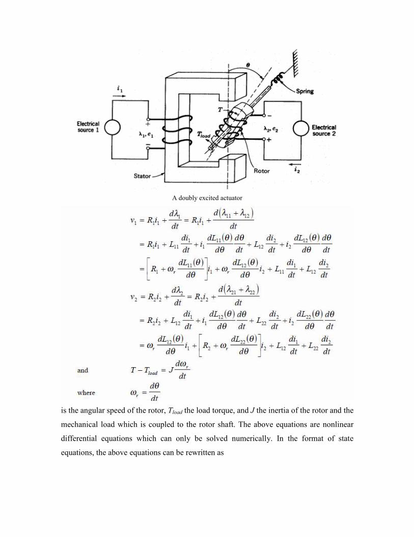
A doubly excited actuator
is the angular speed of the rotor, Tload the load torque, and J the inertia of the rotor and the
mechanical load which is coupled to the rotor shaft. The above equations are nonlinear
differential equations which can only be solved numerically. In the format of state
equations, the above equations can be rewritten as

Together with the specified initial conditions (the state of the system at time zero in terms
of the state variables):
the above state equations can be used to simulate the dynamic performance of the doubly
excited rotating actuator. Following the same rule, we can derive the state equation model
of any electromechanical systems.