Lecture 02-Design of Singly Reinforced Beam in Flexure 02-Design of Singly... · Lecture 02 Design...
32
1 Department of Civil Engineering, University of Engineering and Technology Peshawar, Pakistan Prof. Dr. Qaisar Ali CE 320 Reinforced Concrete Design-I Lecture 02 Design of Singly Reinforced Beam in Flexure By: Prof Dr. Qaisar Ali Civil Engineering Department UET Peshawar [email protected] 1 Department of Civil Engineering, University of Engineering and Technology Peshawar, Pakistan Prof. Dr. Qaisar Ali CE 320 Reinforced Concrete Design-I 2 Topics Addressed Behavior of RC Beams under gravity load Mechanics of RC Beams under gravity load ACI Code Recommendations Design Steps Example
Transcript of Lecture 02-Design of Singly Reinforced Beam in Flexure 02-Design of Singly... · Lecture 02 Design...
1
Department of Civil Engineering, University of Engineering and Technology Peshawar, Pakistan
Prof. Dr. Qaisar Ali CE 320 Reinforced Concrete Design-I
Lecture 02
Design of Singly Reinforced Beam in Flexure
By: Prof Dr. Qaisar Ali
Civil Engineering Department
1
Department of Civil Engineering, University of Engineering and Technology Peshawar, Pakistan
Prof. Dr. Qaisar Ali CE 320 Reinforced Concrete Design-I 2
Topics Addressed
Behavior of RC Beams under gravity load
Mechanics of RC Beams under gravity load
ACI Code Recommendations
Design Steps
Example
2
Department of Civil Engineering, University of Engineering and Technology Peshawar, Pakistan
Prof. Dr. Qaisar Ali CE 320 Reinforced Concrete Design-I 3
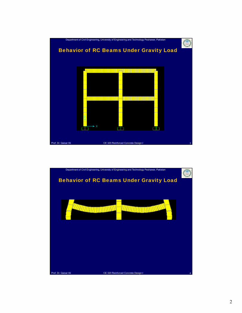
Behavior of RC Beams Under Gravity Load
Department of Civil Engineering, University of Engineering and Technology Peshawar, Pakistan
Prof. Dr. Qaisar Ali CE 320 Reinforced Concrete Design-I 4
Behavior of RC Beams Under Gravity Load
3
Department of Civil Engineering, University of Engineering and Technology Peshawar, Pakistan
Prof. Dr. Qaisar Ali CE 320 Reinforced Concrete Design-I
Beam Test
In order to clearly understand the behavior of RC members
subjected to flexure load only, the response of such members
at three different loading stages is discussed.
5
Behavior of RC Beams Under Gravity Load
Department of Civil Engineering, University of Engineering and Technology Peshawar, Pakistan
Prof. Dr. Qaisar Ali CE 320 Reinforced Concrete Design-I 6
Behavior of RC Beams Under Gravity Load Beam test video
4
Department of Civil Engineering, University of Engineering and Technology Peshawar, Pakistan
Prof. Dr. Qaisar Ali CE 320 Reinforced Concrete Design-I
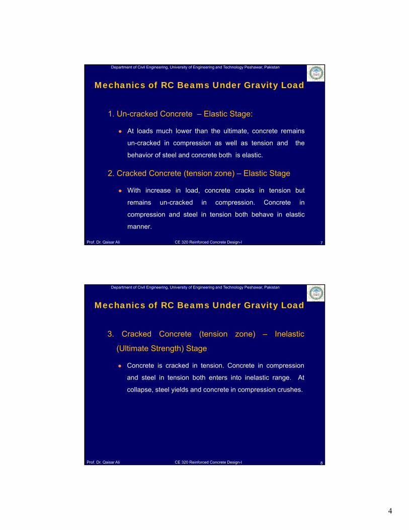
1. Un-cracked Concrete – Elastic Stage:
At loads much lower than the ultimate, concrete remains
un-cracked in compression as well as tension and the
behavior of steel and concrete both is elastic.
2. Cracked Concrete (tension zone) – Elastic Stage
With increase in load, concrete cracks in tension but
remains un-cracked in compression. Concrete in
compression and steel in tension both behave in elastic
manner.
7
Mechanics of RC Beams Under Gravity Load
Department of Civil Engineering, University of Engineering and Technology Peshawar, Pakistan
Prof. Dr. Qaisar Ali CE 320 Reinforced Concrete Design-I
3. Cracked Concrete (tension zone) – Inelastic
(Ultimate Strength) Stage
Concrete is cracked in tension. Concrete in compression
and steel in tension both enters into inelastic range. At
collapse, steel yields and concrete in compression crushes.
8
Mechanics of RC Beams Under Gravity Load
5
Department of Civil Engineering, University of Engineering and Technology Peshawar, Pakistan
Prof. Dr. Qaisar Ali CE 320 Reinforced Concrete Design-I
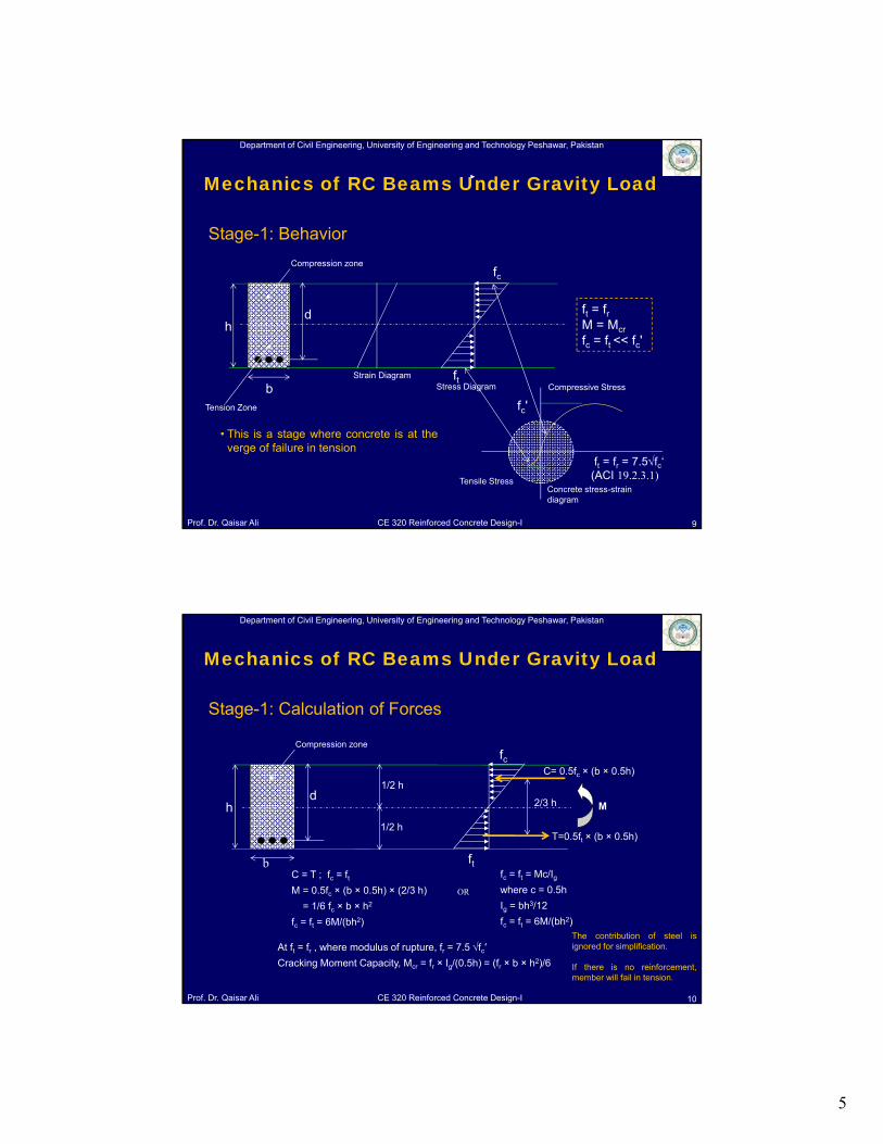
Stage-1: Behavior
ft = frM = Mcr
fc = ft << fc'
fc
ft
h
b
d
Compression zone
Tension Zone
Strain DiagramStress Diagram
Tensile Stress
Compressive Stress
fc'
ft = fr = 7.5fc‘ (ACI 19.2.3.1)
Concrete stress-strain diagram
• This is a stage where concrete is at theverge of failure in tension
9
Mechanics of RC Beams Under Gravity Load
Department of Civil Engineering, University of Engineering and Technology Peshawar, Pakistan
Prof. Dr. Qaisar Ali CE 320 Reinforced Concrete Design-I
bfc = ft = Mc/Igwhere c = 0.5h
Ig = bh3/12
fc = ft = 6M/(bh2)
OR
C = T ; fc = ftM = 0.5fc × (b × 0.5h) × (2/3 h)
= 1/6 fc × b × h2
fc = ft = 6M/(bh2)
At ft = fr , where modulus of rupture, fr = 7.5 fc′
Cracking Moment Capacity, Mcr = fr × Ig/(0.5h) = (fr × b × h2)/6
ft
hd
Compression zonefc
C= 0.5fc × (b × 0.5h)
T=0.5ft × (b × 0.5h)
2/3 h
1/2 h
1/2 h
M
Stage-1: Calculation of Forces
The contribution of steel isignored for simplification.
If there is no reinforcement,member will fail in tension.
10
Mechanics of RC Beams Under Gravity Load
6
Department of Civil Engineering, University of Engineering and Technology Peshawar, Pakistan
Prof. Dr. Qaisar Ali CE 320 Reinforced Concrete Design-I
c
t
fy
0.5fy
c < 0.003
s = fs/Es
0.45fc'
h
b
d
Compression zone
Tension Zone Concrete Cracked
Strain Diagram Stress Diagram
Compressive Stress
fc'
fs = 0.5 fy
Es
0.003
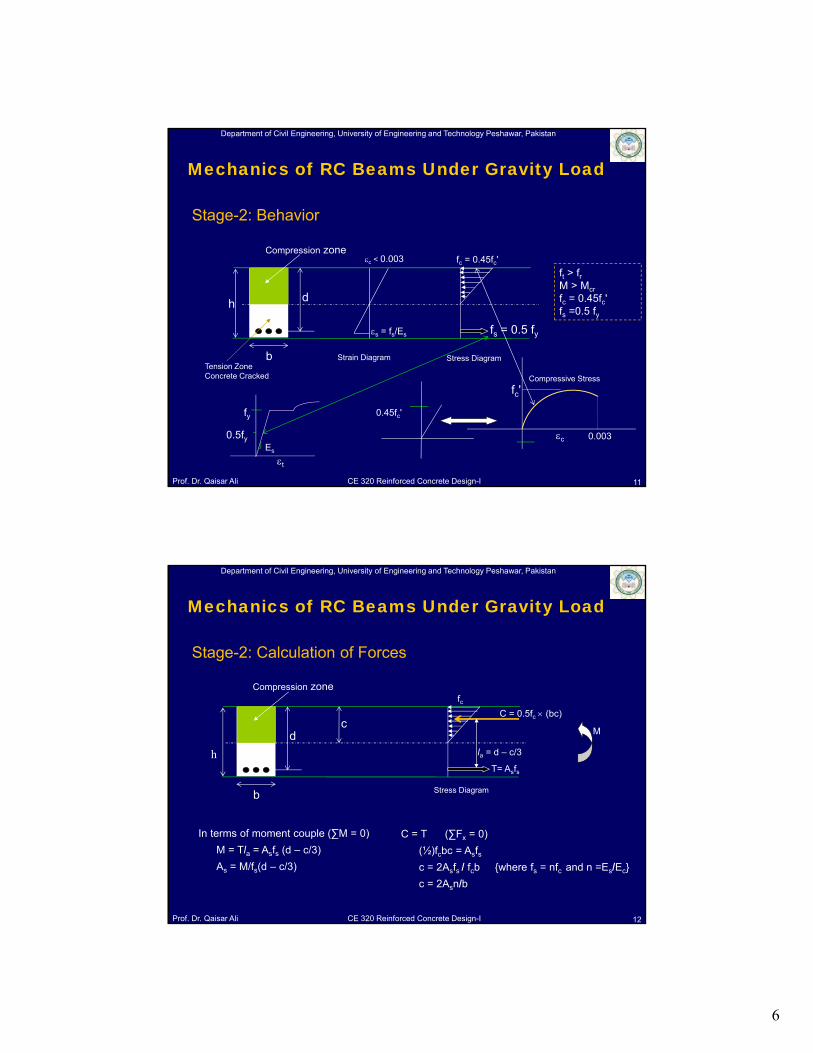
ft > frM > Mcr
fc = 0.45fc'fs =0.5 fy
fc = 0.45fc'
Stage-2: Behavior
11
Mechanics of RC Beams Under Gravity Load
Department of Civil Engineering, University of Engineering and Technology Peshawar, Pakistan
Prof. Dr. Qaisar Ali CE 320 Reinforced Concrete Design-I
h
In terms of moment couple (∑M = 0)
M = Tla = Asfs (d – c/3)
As = M/fs(d – c/3)
C = T (∑Fx = 0)
(½)fcbc = Asfsc = 2Asfs / fcb {where fs = nfc and n =Es/Ec}
c = 2Asn/b
C = 0.5fc (bc)
b
d
Compression zone
Stress Diagram
c
T= Asfs
la = d – c/3
M
fc
Stage-2: Calculation of Forces
12
Mechanics of RC Beams Under Gravity Load
7
Department of Civil Engineering, University of Engineering and Technology Peshawar, Pakistan
Prof. Dr. Qaisar Ali CE 320 Reinforced Concrete Design-I 13
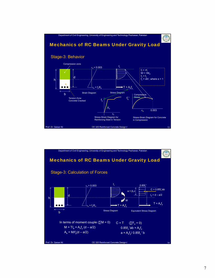
ft > >frM > >Mcr
fs = fyfc = αfc′, where α < 1 h
b
d
Compression zone
Tension Zone Concrete Cracked
Strain Diagram Stress DiagramCompressive Stressfc'
T = Asfy
t
fy
Stress-Strain Diagram for Concrete in Compression
Stress-Strain Diagram for Reinforcing Steel in Tension
c = 0.003
s = fy/Es
Es0.003c
fc
Stage-3: Behavior
Mechanics of RC Beams Under Gravity Load
Department of Civil Engineering, University of Engineering and Technology Peshawar, Pakistan
Prof. Dr. Qaisar Ali CE 320 Reinforced Concrete Design-I
In terms of moment couple (∑M = 0)
M = Tla = Asfy (d – a/2)
As = M/fy(d – a/2)
C = T (∑Fx = 0)
0.85fc ′ab = Asfya = Asfy/ 0.85fc ′ b
T = Asfy
C = 0.85fc′ab
la = d – a/2h
b
d
Stress Diagram
T = Asfy
c = 0.003
s = fy/Es
M
a = β1c
0.85fc′
Equivalent Stress Diagram
fc
Stage-3: Calculation of Forces
14
Mechanics of RC Beams Under Gravity Load
8
Department of Civil Engineering, University of Engineering and Technology Peshawar, Pakistan
Prof. Dr. Qaisar Ali CE 320 Reinforced Concrete Design-I 15
Basic Assumptions: (ACI 22.2)
A plane section before bending remains plane after bending.
Stresses and strain are approximately proportional up to moderate
loads (concrete stress ≤ 0.5fc′). When the load is increased, the
variation in the concrete stress is no longer linear.
Tensile strength of concrete is neglected in the design of reinforced
concrete beams.
The bond between the steel and concrete is perfect and no slip
occurs.
Strain in concrete and reinforcement shall be assumed proportional to
the distance from neutral axis.
Mechanics of RC Beams Under Gravity Load
Department of Civil Engineering, University of Engineering and Technology Peshawar, Pakistan
Prof. Dr. Qaisar Ali CE 320 Reinforced Concrete Design-I 16
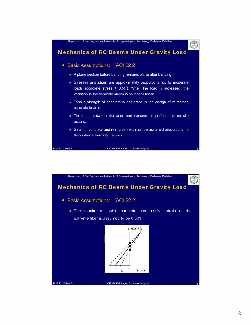
Basic Assumptions: (ACI 22.2)
The maximum usable concrete compressive strain at the
extreme fiber is assumed to be 0.003.
Mechanics of RC Beams Under Gravity Load
9
Department of Civil Engineering, University of Engineering and Technology Peshawar, Pakistan
Prof. Dr. Qaisar Ali CE 320 Reinforced Concrete Design-I 17
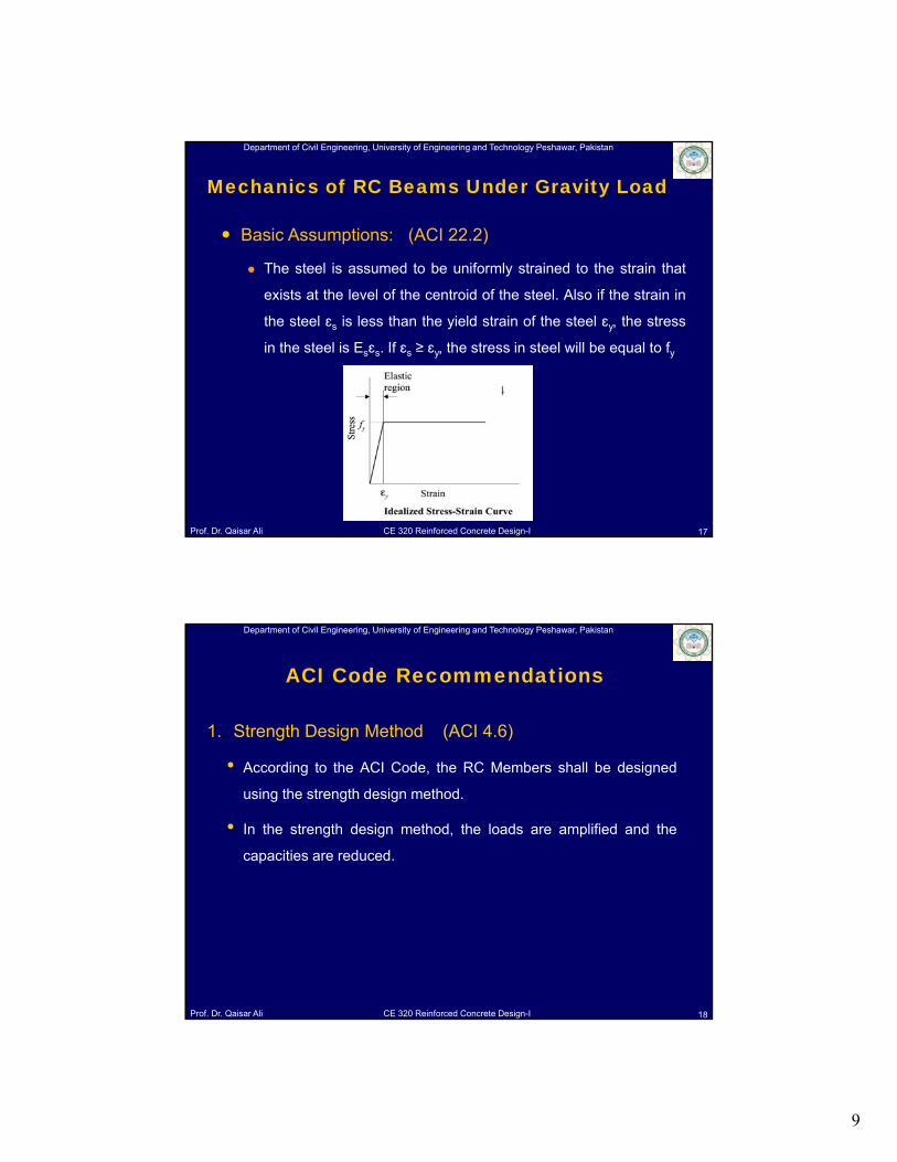
Basic Assumptions: (ACI 22.2)
The steel is assumed to be uniformly strained to the strain that
exists at the level of the centroid of the steel. Also if the strain in
the steel ɛs is less than the yield strain of the steel ɛy, the stress
in the steel is Esɛs. If ɛs ≥ ɛy, the stress in steel will be equal to fyFigure 9
Mechanics of RC Beams Under Gravity Load
Department of Civil Engineering, University of Engineering and Technology Peshawar, Pakistan
Prof. Dr. Qaisar Ali CE 320 Reinforced Concrete Design-I
1. Strength Design Method (ACI 4.6)
• According to the ACI Code, the RC Members shall be designed
using the strength design method.
• In the strength design method, the loads are amplified and the
capacities are reduced.
18
ACI Code Recommendations
10
Department of Civil Engineering, University of Engineering and Technology Peshawar, Pakistan
Prof. Dr. Qaisar Ali CE 320 Reinforced Concrete Design-I
1. Strength Design Method
• The loads are amplified in the following manner.
• Load combinations (ACI 5.3)
WU = 1.2 WD + 1.6 WL
MU = 1.2 MD + 1.6 ML
Where; WD = Dead load and WL = Service Live load
WU = Amplified load or Ultimate load
MU = Amplified moment or Ultimate moment
19
ACI Code Recommendations
Department of Civil Engineering, University of Engineering and Technology Peshawar, Pakistan
Prof. Dr. Qaisar Ali CE 320 Reinforced Concrete Design-I
1. Strength Design Method
• According to strength design method the resisting member
flexural capacity calculated from specified dimension (size of
members) and material strength called as the nominal flexural
capacity Mn = Asfy (d - a/2) shall be reduced by multiplying it with
strength reduction factor Φ = 0.9, to get the design flexural
capacity (Md).
Md = Φ Mn ; Φ = 0.9
For no failure; Φ Mn = Mu
20
ACI Code Recommendations
11
Department of Civil Engineering, University of Engineering and Technology Peshawar, Pakistan
Prof. Dr. Qaisar Ali CE 320 Reinforced Concrete Design-I
2. Nominal Flexural Capacity of RC Member
• The nominal flexural capacity of RC Members shall be calculated
from the conditions corresponding to stage 3.
• ACI-R21.2.2 — The Nominal Flexural Strength (Mn) of a RC
member is reached when the strain in the extreme
compression fiber reaches the assumed strain limit of 0.003,
(i.e. strains at stage 3.)
• In other words, the member finally fails by crushing of concrete,
even if steel in tension has yielded well before crushing of
concrete.
21
ACI Code Recommendations
Department of Civil Engineering, University of Engineering and Technology Peshawar, Pakistan
Prof. Dr. Qaisar Ali CE 320 Reinforced Concrete Design-I
3. Maximum Reinforcement (Asmax): (ACI 21.2.2)
• When concrete crushes at εc = 0.003, depending on the amount of
steel (As) present as tension reinforcement, following conditions are
possible for steel strain (εs)
1. εs = εy Balanced Failure Condition, Brittle Failure
2. εs < εy Over reinforced condition, Brittle failure
3. εs > εy Under Reinforced Condition, Ductile Failure
• For relative high amount of tension reinforcement, failure may occur
under conditions 1 & 2, causing brittle failure. It is for this reason
that ACI code restricts maximum amount of reinforcement in
member subjected to flexural load only.
22
ACI Code Recommendations
12
Department of Civil Engineering, University of Engineering and Technology Peshawar, Pakistan
Prof. Dr. Qaisar Ali CE 320 Reinforced Concrete Design-I
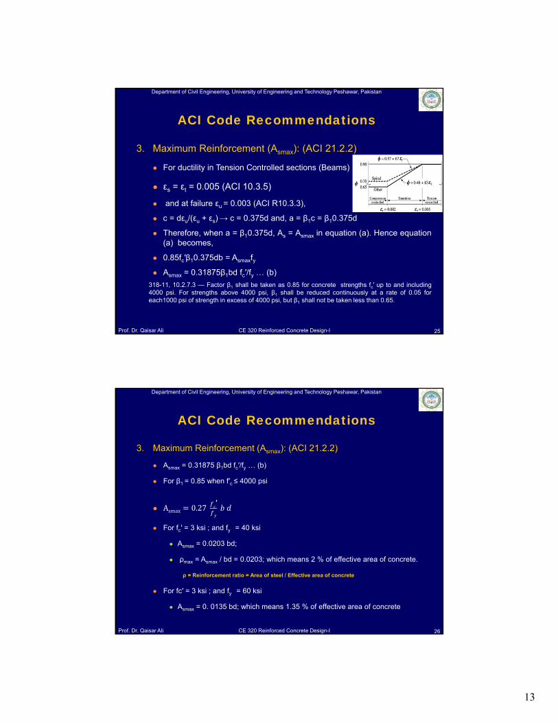
3. Maximum Reinforcement (Asmax): (ACI 21.2.2)
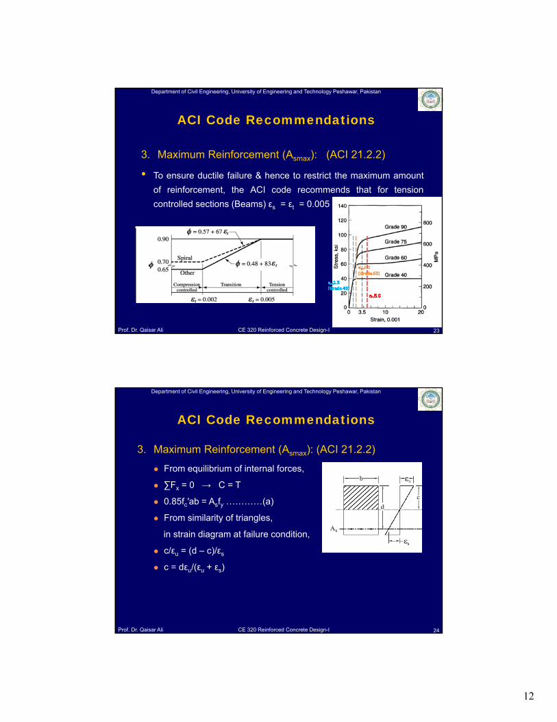
• To ensure ductile failure & hence to restrict the maximum amount
of reinforcement, the ACI code recommends that for tension
controlled sections (Beams) εs = εt = 0.005
23
ACI Code Recommendations
Department of Civil Engineering, University of Engineering and Technology Peshawar, Pakistan
Prof. Dr. Qaisar Ali CE 320 Reinforced Concrete Design-I
3. Maximum Reinforcement (Asmax): (ACI 21.2.2)
From equilibrium of internal forces,
∑Fx = 0 → C = T
0.85fc′ab = Asfy …………(a)
From similarity of triangles,
in strain diagram at failure condition,
c/εu = (d – c)/εs
c = dεu/(εu + εs)
24
ACI Code Recommendations
13
Department of Civil Engineering, University of Engineering and Technology Peshawar, Pakistan
Prof. Dr. Qaisar Ali CE 320 Reinforced Concrete Design-I
3. Maximum Reinforcement (Asmax): (ACI 21.2.2)
For ductility in Tension Controlled sections (Beams)
εs = εt = 0.005 (ACI 10.3.5)
and at failure εu = 0.003 (ACI R10.3.3),
c = dεu/(εu + εs) → c = 0.375d and, a = β1c = β10.375d
Therefore, when a = β10.375d, As = Asmax in equation (a). Hence equation(a) becomes,
0.85fc′β10.375db = Asmaxfy
Asmax = 0.31875β1bd fc′/fy … (b)
318-11, 10.2.7.3 — Factor β1 shall be taken as 0.85 for concrete strengths fc′ up to and including4000 psi. For strengths above 4000 psi, β1 shall be reduced continuously at a rate of 0.05 foreach1000 psi of strength in excess of 4000 psi, but β1 shall not be taken less than 0.65.
25
ACI Code Recommendations
Department of Civil Engineering, University of Engineering and Technology Peshawar, Pakistan
Prof. Dr. Qaisar Ali CE 320 Reinforced Concrete Design-I
3. Maximum Reinforcement (Asmax): (ACI 21.2.2)
Asmax = 0.31875 β1bd fc′/fy … (b)
For β1 = 0.85 when f′c ≤ 4000 psi
Asmax 0.27′
For fc′ = 3 ksi ; and fy = 40 ksi
Asmax = 0.0203 bd;
ρmax = Asmax / bd = 0.0203; which means 2 % of effective area of concrete.
For fc′ = 3 ksi ; and fy = 60 ksi
Asmax = 0. 0135 bd; which means 1.35 % of effective area of concrete
26
ACI Code Recommendations
ρ = Reinforcement ratio = Area of steel / Effective area of concrete
14
Department of Civil Engineering, University of Engineering and Technology Peshawar, Pakistan
Prof. Dr. Qaisar Ali CE 320 Reinforced Concrete Design-I
Video of beam having reinforcement more than maximum reinforcement
27
ACI Code Recommendations
Department of Civil Engineering, University of Engineering and Technology Peshawar, Pakistan
Prof. Dr. Qaisar Ali CE 320 Reinforced Concrete Design-I
4. Minimum Reinforcement (Asmin): (ACI 9.6.1.2)
At every section of a flexural member where tensile
reinforcement is required by analysis, the area As provided
shall not be less than that given by ρminbd where, ρmin is equal
to the greater of 3√ (fc′)/fy and 200/fy.
Asmin 3
28
ACI Code Recommendations
For a statically determinate beam, this reinforcement shall be doubled.
15
Department of Civil Engineering, University of Engineering and Technology Peshawar, Pakistan
Prof. Dr. Qaisar Ali CE 320 Reinforced Concrete Design-I 29
ACI Code Recommendations• Video of beam having reinforcement less than minimum reinforcement
Department of Civil Engineering, University of Engineering and Technology Peshawar, Pakistan
Prof. Dr. Qaisar Ali CE 320 Reinforced Concrete Design-I
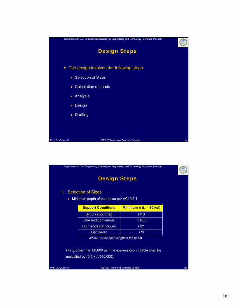
ρmax and ρmin for various values of fc′ and fy
30
Table 01: Maximum & Minimum Reinforcement Ratios
fc′ (psi) 3000 4000 5000
fy (psi) 40000 60000 40000 60000 40000 60000
ρmin 0.005 0.0033 0.005 0.0033 0.0053 0.0035
ρmax 0.0203 0.0135 0.027 0.018 0.0319 0.0213
ACI Code Recommendations
16
Department of Civil Engineering, University of Engineering and Technology Peshawar, Pakistan
Prof. Dr. Qaisar Ali CE 320 Reinforced Concrete Design-I
The design involves the following steps:
Selection of Sizes
Calculation of Loads
Analysis
Design
Drafting
31
Design Steps
Department of Civil Engineering, University of Engineering and Technology Peshawar, Pakistan
Prof. Dr. Qaisar Ali CE 320 Reinforced Concrete Design-I
1. Selection of Sizes
Minimum depth of beams as per ACI 9.3.1
Where l is the span length of the beam
32
Design Steps
Support Conditions Minimum h (fy = 60 ksi)
Simply supported l /16
One end continuous l /18.5
Both ends continuous l /21
Cantilever l /8
For fy other than 60,000 psi, the expressions in Table shall be
multiplied by (0.4 + fy/100,000).
17
Department of Civil Engineering, University of Engineering and Technology Peshawar, Pakistan
Prof. Dr. Qaisar Ali CE 320 Reinforced Concrete Design-I
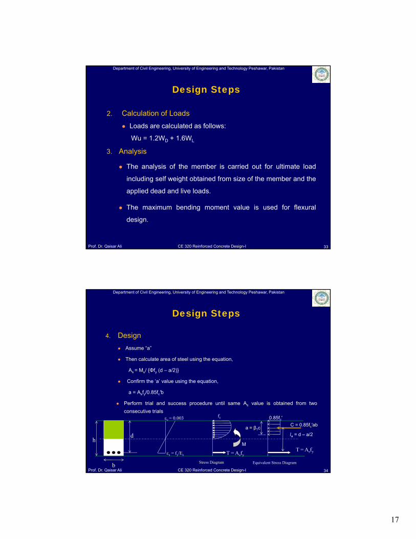
2. Calculation of Loads
Loads are calculated as follows:
Wu = 1.2WD + 1.6WL
3. Analysis
The analysis of the member is carried out for ultimate load
including self weight obtained from size of the member and the
applied dead and live loads.
The maximum bending moment value is used for flexural
design.
33
Design Steps
Department of Civil Engineering, University of Engineering and Technology Peshawar, Pakistan
Prof. Dr. Qaisar Ali CE 320 Reinforced Concrete Design-I
4. Design
Assume “a”
Then calculate area of steel using the equation,
As = Mu/ {Φfy (d – a/2)}
Confirm the ‘a’ value using the equation,
a = Asfy/0.85fc′b
Perform trial and success procedure until same As value is obtained from two
consecutive trials
34
Design Steps
T = Asfy
C = 0.85fc′ab
la = d – a/2h
b
d
Stress Diagram
T = Asfy
c = 0.003
s = fy/Es
M
a = β1c
0.85fc′
Equivalent Stress Diagram
fc
18
Department of Civil Engineering, University of Engineering and Technology Peshawar, Pakistan
Prof. Dr. Qaisar Ali CE 320 Reinforced Concrete Design-I
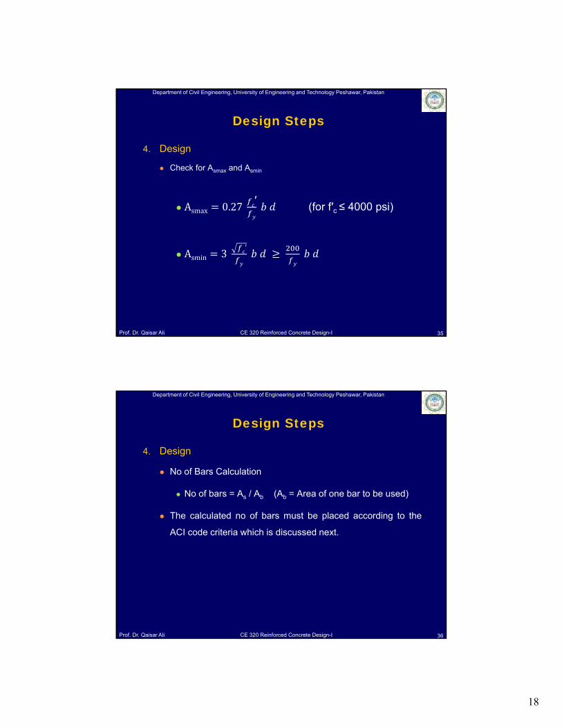
4. Design
Check for Asmax and Asmin
Asmax 0.27 ′ (for f′c ≤ 4000 psi)
Asmin 3
35
Design Steps
Department of Civil Engineering, University of Engineering and Technology Peshawar, Pakistan
Prof. Dr. Qaisar Ali CE 320 Reinforced Concrete Design-I
4. Design
No of Bars Calculation
No of bars = As / Ab (Ab = Area of one bar to be used)
The calculated no of bars must be placed according to the
ACI code criteria which is discussed next.
36
Design Steps
19
Department of Civil Engineering, University of Engineering and Technology Peshawar, Pakistan
Prof. Dr. Qaisar Ali CE 320 Reinforced Concrete Design-I
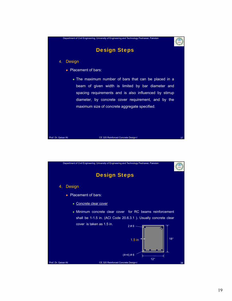
4. Design
Placement of bars:
The maximum number of bars that can be placed in a
beam of given width is limited by bar diameter and
spacing requirements and is also influenced by stirrup
diameter, by concrete cover requirement, and by the
maximum size of concrete aggregate specified.
37
Design Steps
Department of Civil Engineering, University of Engineering and Technology Peshawar, Pakistan
Prof. Dr. Qaisar Ali CE 320 Reinforced Concrete Design-I
4. Design
Placement of bars:
Concrete clear cover
Minimum concrete clear cover for RC beams reinforcement
shall be 1-1.5 in. (ACI Code 20.6.3.1 ). Usually concrete clear
cover is taken as 1.5 in.
38
Design Steps
(4+4) # 6
18″
12″
2 # 6
1.5 in
20
Department of Civil Engineering, University of Engineering and Technology Peshawar, Pakistan
Prof. Dr. Qaisar Ali CE 320 Reinforced Concrete Design-I
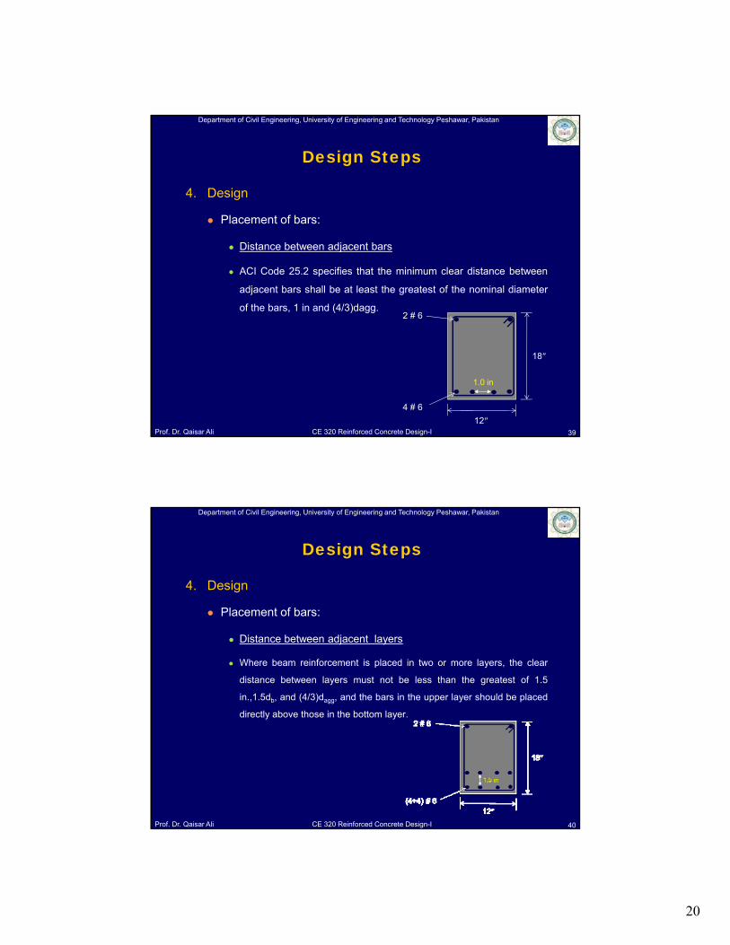
4. Design
Placement of bars:
Distance between adjacent bars
ACI Code 25.2 specifies that the minimum clear distance between
adjacent bars shall be at least the greatest of the nominal diameter
of the bars, 1 in and (4/3)dagg.
39
Design Steps
4 # 6
18″
12″
2 # 6
1.0 in
Department of Civil Engineering, University of Engineering and Technology Peshawar, Pakistan
Prof. Dr. Qaisar Ali CE 320 Reinforced Concrete Design-I
4. Design
Placement of bars:
Distance between adjacent layers
Where beam reinforcement is placed in two or more layers, the clear
distance between layers must not be less than the greatest of 1.5
in.,1.5db, and (4/3)dagg, and the bars in the upper layer should be placed
directly above those in the bottom layer.
40
Design Steps
21
Department of Civil Engineering, University of Engineering and Technology Peshawar, Pakistan
Prof. Dr. Qaisar Ali CE 320 Reinforced Concrete Design-I
4. Design
Placement of bars:
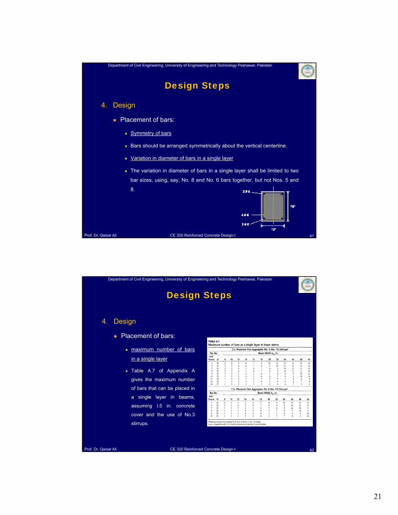
Symmetry of bars
Bars should be arranged symmetrically about the vertical centerline.
Variation in diameter of bars in a single layer
The variation in diameter of bars in a single layer shall be limited to two
bar sizes, using, say, No. 8 and No. 6 bars together, but not Nos. 5 and
8.
41
Design Steps
Department of Civil Engineering, University of Engineering and Technology Peshawar, Pakistan
Prof. Dr. Qaisar Ali CE 320 Reinforced Concrete Design-I
Design Steps
4. Design
Placement of bars:
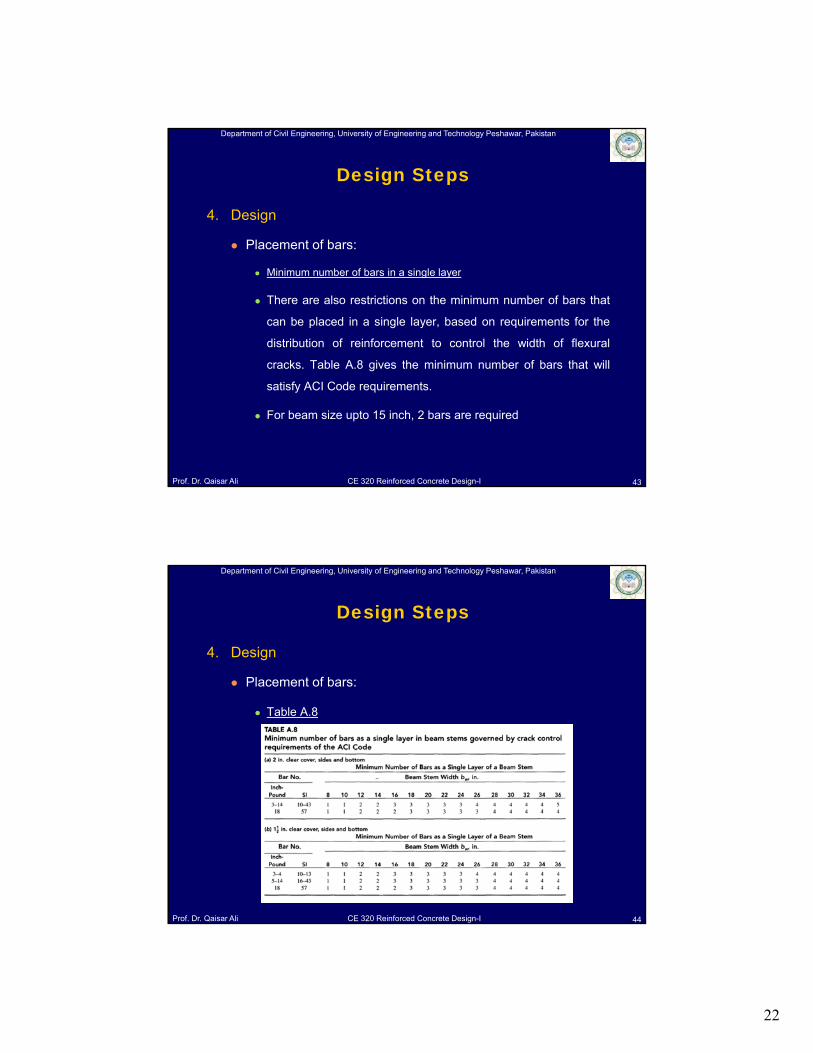
maximum number of bars
in a single layer
Table A.7 of Appendix A
gives the maximum number
of bars that can be placed in
a single layer in beams,
assuming I.5 in. concrete
cover and the use of No.3
stirrups.
42
22
Department of Civil Engineering, University of Engineering and Technology Peshawar, Pakistan
Prof. Dr. Qaisar Ali CE 320 Reinforced Concrete Design-I
4. Design
Placement of bars:
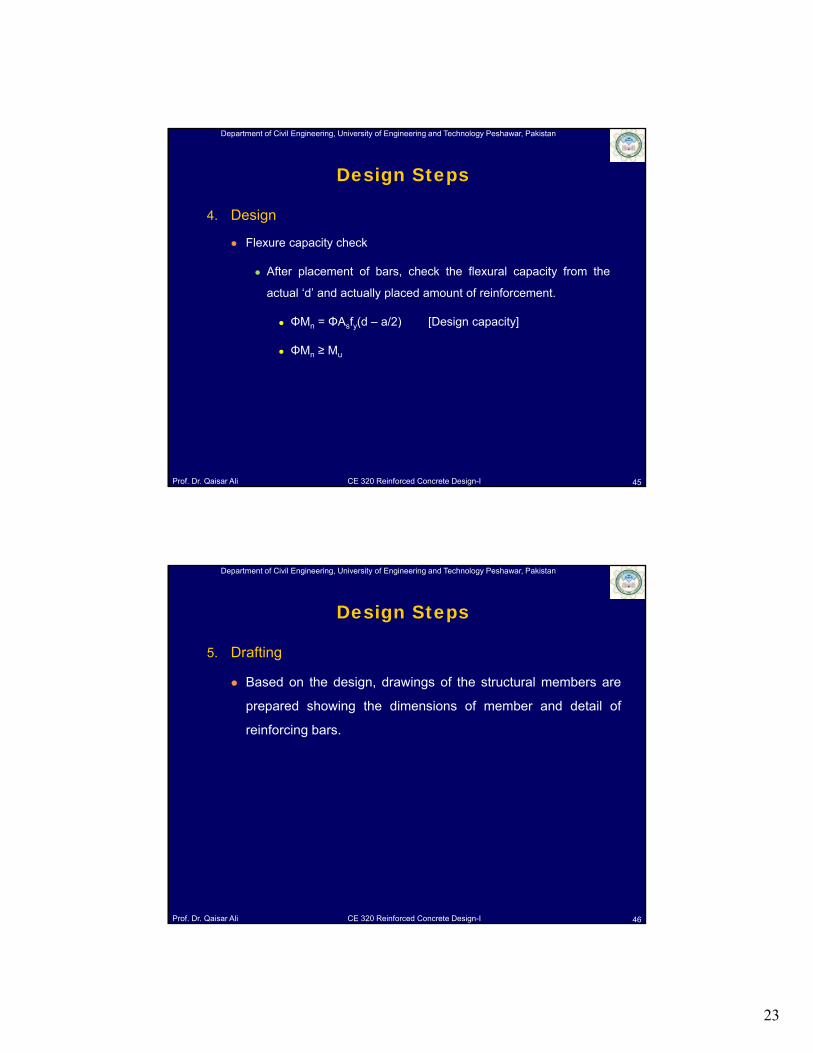
Minimum number of bars in a single layer
There are also restrictions on the minimum number of bars that
can be placed in a single layer, based on requirements for the
distribution of reinforcement to control the width of flexural
cracks. Table A.8 gives the minimum number of bars that will
satisfy ACI Code requirements.
For beam size upto 15 inch, 2 bars are required
43
Design Steps
Department of Civil Engineering, University of Engineering and Technology Peshawar, Pakistan
Prof. Dr. Qaisar Ali CE 320 Reinforced Concrete Design-I
4. Design
Placement of bars:
Table A.8
44
Design Steps
23
Department of Civil Engineering, University of Engineering and Technology Peshawar, Pakistan
Prof. Dr. Qaisar Ali CE 320 Reinforced Concrete Design-I
4. Design
Flexure capacity check
After placement of bars, check the flexural capacity from the
actual ‘d’ and actually placed amount of reinforcement.
ΦMn = ΦAsfy(d – a/2) [Design capacity]
ΦMn ≥ Mu
45
Design Steps
Department of Civil Engineering, University of Engineering and Technology Peshawar, Pakistan
Prof. Dr. Qaisar Ali CE 320 Reinforced Concrete Design-I
5. Drafting
Based on the design, drawings of the structural members are
prepared showing the dimensions of member and detail of
reinforcing bars.
46
Design Steps
24
Department of Civil Engineering, University of Engineering and Technology Peshawar, Pakistan
Prof. Dr. Qaisar Ali CE 320 Reinforced Concrete Design-I
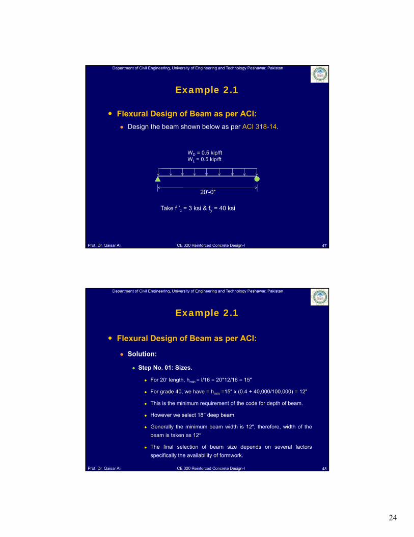
Flexural Design of Beam as per ACI:
Design the beam shown below as per ACI 318-14.
47
WD = 0.5 kip/ftWL = 0.5 kip/ft
20′-0″
Example 2.1
Take f ′c = 3 ksi & fy = 40 ksi
Department of Civil Engineering, University of Engineering and Technology Peshawar, Pakistan
Prof. Dr. Qaisar Ali CE 320 Reinforced Concrete Design-I
Flexural Design of Beam as per ACI:
Solution:
Step No. 01: Sizes.
For 20′ length, hmin = l/16 = 20*12/16 = 15″
For grade 40, we have = hmin =15″ x (0.4 + 40,000/100,000) = 12″
This is the minimum requirement of the code for depth of beam.
However we select 18″ deep beam.
Generally the minimum beam width is 12″, therefore, width of the
beam is taken as 12″
The final selection of beam size depends on several factors
specifically the availability of formwork.
48
Example 2.1
25
Department of Civil Engineering, University of Engineering and Technology Peshawar, Pakistan
Prof. Dr. Qaisar Ali CE 320 Reinforced Concrete Design-I
Flexural Design of Beam as per ACI:
Solution:
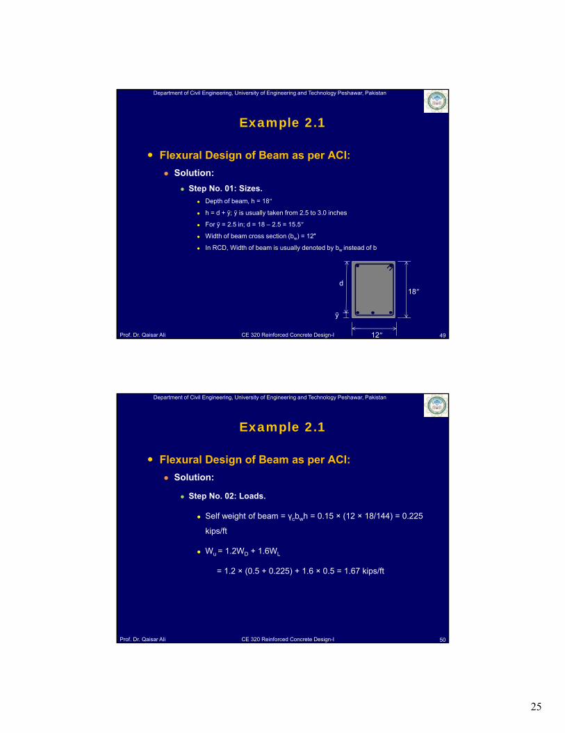
Step No. 01: Sizes.
Depth of beam, h = 18″
h = d + ȳ; ȳ is usually taken from 2.5 to 3.0 inches
For ȳ = 2.5 in; d = 18 – 2.5 = 15.5″
Width of beam cross section (bw) = 12″
In RCD, Width of beam is usually denoted by bw instead of b
49
Example 2.1
18″
12″
d
ȳ
Department of Civil Engineering, University of Engineering and Technology Peshawar, Pakistan
Prof. Dr. Qaisar Ali CE 320 Reinforced Concrete Design-I
Flexural Design of Beam as per ACI:
Solution:
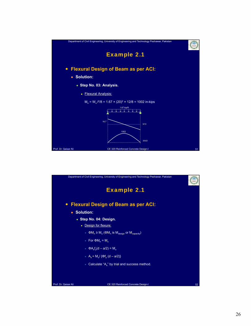
Step No. 02: Loads.
Self weight of beam = γcbwh = 0.15 × (12 × 18/144) = 0.225
kips/ft
Wu = 1.2WD + 1.6WL
= 1.2 × (0.5 + 0.225) + 1.6 × 0.5 = 1.67 kips/ft
50
Example 2.1
26
Department of Civil Engineering, University of Engineering and Technology Peshawar, Pakistan
Prof. Dr. Qaisar Ali CE 320 Reinforced Concrete Design-I
Flexural Design of Beam as per ACI:
Solution:
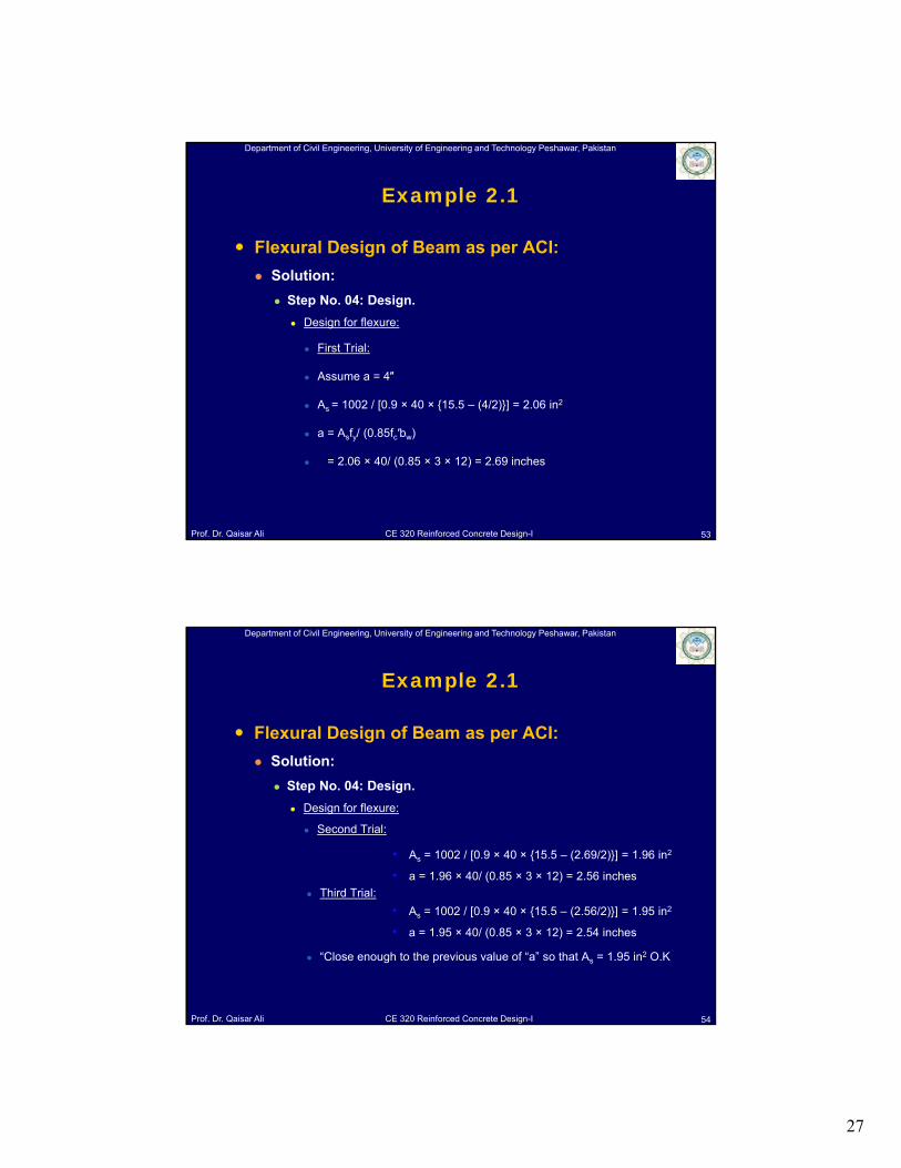
Step No. 03: Analysis.
Flexural Analysis:
Mu = Wu l2/8 = 1.67 × (20)2 × 12/8 = 1002 in-kips
51
SFD
BMD
1.67 kip/ft
1002
16.7
Example 2.1
Department of Civil Engineering, University of Engineering and Technology Peshawar, Pakistan
Prof. Dr. Qaisar Ali CE 320 Reinforced Concrete Design-I
Flexural Design of Beam as per ACI:
Solution:
Step No. 04: Design.
Design for flexure:
ΦMn ≥ Mu (ΦMn is Mdesign or Mcapacity)
For ΦMn = Mu
ΦAsfy(d – a/2) = Mu
As = Mu/ {Φfy (d – a/2)}
Calculate “As” by trial and success method.
52
Example 2.1
27
Department of Civil Engineering, University of Engineering and Technology Peshawar, Pakistan
Prof. Dr. Qaisar Ali CE 320 Reinforced Concrete Design-I
Flexural Design of Beam as per ACI:
Solution:
Step No. 04: Design.
Design for flexure:
First Trial:
Assume a = 4″
As = 1002 / [0.9 × 40 × {15.5 – (4/2)}] = 2.06 in2
a = Asfy/ (0.85fc′bw)
= 2.06 × 40/ (0.85 × 3 × 12) = 2.69 inches
53
Example 2.1
Department of Civil Engineering, University of Engineering and Technology Peshawar, Pakistan
Prof. Dr. Qaisar Ali CE 320 Reinforced Concrete Design-I
Flexural Design of Beam as per ACI:
Solution:
Step No. 04: Design.
Design for flexure:
Second Trial:
Third Trial:
“Close enough to the previous value of “a” so that As = 1.95 in2 O.K
54
• As = 1002 / [0.9 × 40 × {15.5 – (2.69/2)}] = 1.96 in2
• a = 1.96 × 40/ (0.85 × 3 × 12) = 2.56 inches
• As = 1002 / [0.9 × 40 × {15.5 – (2.56/2)}] = 1.95 in2
• a = 1.95 × 40/ (0.85 × 3 × 12) = 2.54 inches
Example 2.1

28
Department of Civil Engineering, University of Engineering and Technology Peshawar, Pakistan
Prof. Dr. Qaisar Ali CE 320 Reinforced Concrete Design-I
Flexural Design of Beam as per ACI:
Solution:
Step No. 04: Design.
Design for flexure:
Check for maximum and minimum reinforcement allowed by ACI:
Asmin = 3 ( f′ /fy) bwd ≥ (200/fy) bwd
3 ( f′ /fy) bwd = 3 × ( 3000 /40000) bwd = 0.004 x 12 x15.5 = 0.744 in2
(200/fy) bwd = (200/40000) x12 × 15.5 = 0.93 in2
Asmin = 0.93x2 in2 = 1.86 in2 (Statically determinate beam)
55
Example 2.1
Department of Civil Engineering, University of Engineering and Technology Peshawar, Pakistan
Prof. Dr. Qaisar Ali CE 320 Reinforced Concrete Design-I
Flexural Design of Beam as per ACI:
Solution:
Step No. 04: Design.
Design for flexure:
Asmax = 0.27 (fc′ / fy) bwd = 0.27 x (3/40) x 12 × 15.5 = 3.76 in2
Asmin (1.86) < As (1.95) < Asmax (3.76) O.K
56
Example 2.1
29
Department of Civil Engineering, University of Engineering and Technology Peshawar, Pakistan
Prof. Dr. Qaisar Ali CE 320 Reinforced Concrete Design-I
Flexural Design of Beam as per ACI:
Solution:
Step No. 04: Design.
Design for flexure:
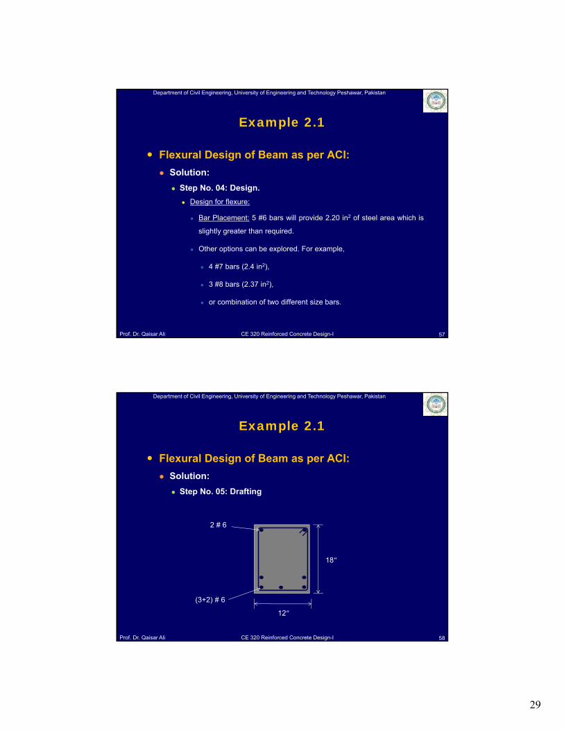
Bar Placement: 5 #6 bars will provide 2.20 in2 of steel area which is
slightly greater than required.
Other options can be explored. For example,
4 #7 bars (2.4 in2),
3 #8 bars (2.37 in2),
or combination of two different size bars.
57
Example 2.1
Department of Civil Engineering, University of Engineering and Technology Peshawar, Pakistan
Prof. Dr. Qaisar Ali CE 320 Reinforced Concrete Design-I
Flexural Design of Beam as per ACI:
Solution:
Step No. 05: Drafting
58
Example 2.1
(3+2) # 6
18″
12″
2 # 6
30
Department of Civil Engineering, University of Engineering and Technology Peshawar, Pakistan
Prof. Dr. Qaisar Ali CE 320 Reinforced Concrete Design-I
Example 2.1
Flexural Design of Beam as perACI:
Solution:
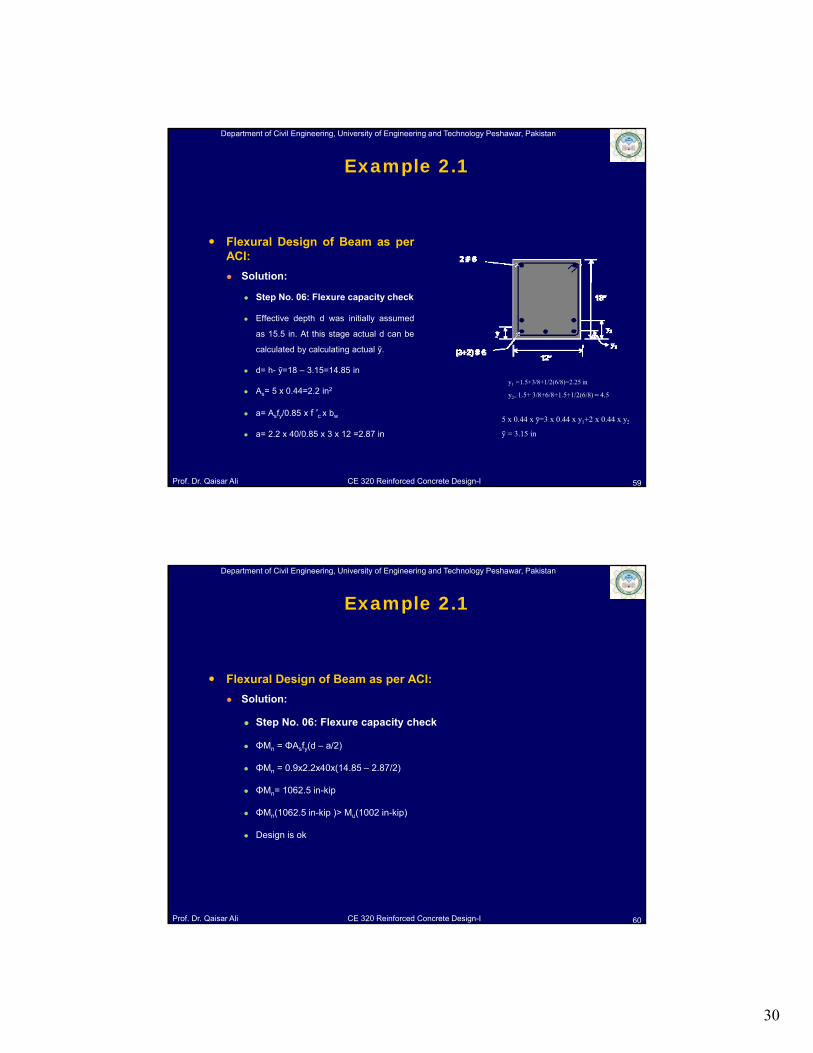
Step No. 06: Flexure capacity check
Effective depth d was initially assumed
as 15.5 in. At this stage actual d can be
calculated by calculating actual ȳ.
d= h- ȳ=18 – 3.15=14.85 in
As= 5 x 0.44=2.2 in2
a= Asfy/0.85 x f ′c x bw
a= 2.2 x 40/0.85 x 3 x 12 =2.87 in
59
5 x 0.44 x ȳ=3 x 0.44 x y1+2 x 0.44 x y2
ȳ = 3.15 in
y1 =1.5+3/8+1/2(6/8)=2.25 in
y2= 1.5+ 3/8+6/8+1.5+1/2(6/8) = 4.5
Department of Civil Engineering, University of Engineering and Technology Peshawar, Pakistan
Prof. Dr. Qaisar Ali CE 320 Reinforced Concrete Design-I
Example 2.1
Flexural Design of Beam as per ACI:
Solution:
Step No. 06: Flexure capacity check
ΦMn = ΦAsfy(d – a/2)
ΦMn = 0.9x2.2x40x(14.85 – 2.87/2)
ΦMn= 1062.5 in-kip
ΦMn(1062.5 in-kip )> Mu(1002 in-kip)
Design is ok
60
31
Department of Civil Engineering, University of Engineering and Technology Peshawar, Pakistan
Prof. Dr. Qaisar Ali CE 320 Reinforced Concrete Design-I
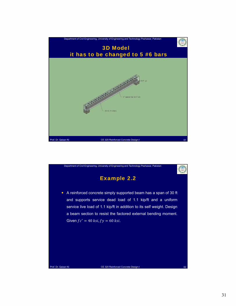
3D Modelit has to be changed to 5 #6 bars
SketchUp Model
61
Department of Civil Engineering, University of Engineering and Technology Peshawar, Pakistan
Prof. Dr. Qaisar Ali CE 320 Reinforced Concrete Design-I
A reinforced concrete simply supported beam has a span of 30 ft
and supports service dead load of 1.1 kip/ft and a uniform
service live load of 1.1 kip/ft in addition to its self weight. Design
a beam section to resist the factored external bending moment.
Given 40 , 60 .
62
Example 2.2
32
Department of Civil Engineering, University of Engineering and Technology Peshawar, Pakistan
Prof. Dr. Qaisar Ali CE 320 Reinforced Concrete Design-I
Design of Concrete Structures 14th / 15th edition by Nilson, Darwin
and Dolan.
ACI 318-14
63
References