ultraSonic energy meter, flow meter De/DB SerieS Flow/PDFs/DE-DB Series Catalog Page.pdfThe...
4
FLOW 368 FLOW 6 MORE OPTIONS AVAILABLE ON KELE.COM kele.com 877-8269037 USA September 2016 Supply Voltage 95-264 VAC, 47-63 Hz @ 17 VA 20-28 VAC, 47-63 Hz @ 8.4 VA 10-28 VDC @ 200 mA Accuracy Flow: ± 1.0% of reading above 1 fps (0.3 mps) velocity, ± 0.01% of reading below 1 fps (0.3 mps) Temperature (DE only): 0.45°F (0.25°C), NIST certification inlcuded Signal Output DE: 4-20 mA @ 400Ω internal power, can span negative-to-positive flow/ energy rates DB: 4-20 mA @ 400Ω internal power, can span negative-to-positive flow/ energy rates; two 0-1,000 Hz open collector transistors that can be configured for flow rate, alarming or totalizing Frequency DTTS small transducers: 2 MHz DTTN remote transducers: 1 MHz DTTL large pipe transducers: 500 kHz Repeatability 0.5% of reading Sensitivity Flow: 0.001 fps (.0003 mps) Temperature: 0.05°F (.025°C) Velocity Range 0.1 to 40 fps (feet/second), 0.03 to 12.4 mps (meters/second), bi-directional Wiring Transducer cables: RG59 coaxial 75Ω or Twinaxial 78Ω, (optional armored conduit), maximum length 990' (300 m) in 10' (3m) increments RTDs (DE meters only): Platinum 385, 1 kΩ, 3-wire PVC jacket cable Conduit Opening Two 1/2" FNPT and one 3/4" FNPT Cable Length Remote transducer models available with 20' (6.1m), 50' (15m), or 100' (30m) cables Communication USB: 2.0 for connection to PC running ULTRALINK™ configuration utility RS485: Modbus RTU command set, ENERGYLINK network monitoring software 10/100 Base-T: RJ45 communication via Modbus TCP/IP, Ethernet/IP and BACnet ® /IP Configuration PC running free ULTRALINK™ software or via integral display keypad (limited access to parameters) Display Two-line LCD, LED backlit, top row: 0.7" (1.8 cm) height, 7-segment; bottom row: .35" (0.9 cm) height, 14-segment; flow rate and totalization indication Engineering Units DB: flow rate in gallons, cubic feet, million gallons, barrels, acre-feet, lbs., meters, cubic meters, liters, million liters, kg. DE: flow rates above plus BTU, MBTU, MMBTU, Tons, kJ, kW, MW Pipe Size Range 1/2" (1.2 cm) and larger Media Compatibility Most clean liquids or liquids with some suspended solids or aeration; get factory approval for glycol applications Materials Of Construction Enclosure: powder-coated aluminum, polycarbonate, stainless steel, polyurethane, nickel-plated steel mounting brackets, Transducers: NEMA 6 (IP67), PVC/CPVC, Ultem ® , Nylon cord grip, PVC cable jacket Operating Temperature -40° to 185°F (-40° to 85°C); remote DTTS/DTTN transducers have upper limit of 250°F (121°C) and high temperature DTTH have upper limit of 400°F (200°C) Enclosure Rating NEMA 4 (IP65) as long as a liquid- tight connectors are used Approvals CSA C22.2 No. 61010-1 (24 VDC, 120 VAC only); CE EN61326-1:2006 Warranty 1 year ULTRASONIC ENERGY METER, FLOW METER DE/DB SERIES DESCRIPTION The Dynasonics DE Series ultrasonic energy meter and DB Series ultrasonic flow meter attach externally to water distribution piping to measure flow rate and (the DE Series) supply/return temperature difference to calculate energy consumption. Since they are non-invasive, they add no pressure head loss to the system and can be installed on existing piping systems without shutdown or interruption. Installation is easy and fast, there are no moving parts, and they measure bi-directional flow. The DE energy meter measures energy usage in BTU, MBTU, MMBTU, Tons, kJ, kW, MW and is perfect for retrofit of existing hot water or chilled water hydronic systems. Network communication models include Modbus RTU over RS485, Modbus TCP/IP, and Ethernet communication includes BACNet ® /IP, EtherNet/IP ® protocols. The DE and DB meters have a backlit display (available with or without a keypad interface), a USB port for programming, and integral or remote clamp-on flow transducer configurations. The DE Series uses strap-on RTD temperature sensors (immersion sensors are also available). The DE and DB meters work with pipe sizes 1/2" and up, are available in 24 VAC, 120 VAC, or 24 VDC power, and have a 4-20 mA analog output for flow rate and a pulse output for totalizing. Free ULTRALINK™ software is used to configure the meters. SPECIFICATIONS FEATURES • Backlit display for easy reading in low light • USB Port for configuration and monitoring • No fluid contact means no fluid compatibility issues, no pressure drop, and no plant shutdown necessary for installation • Bi-directional flow measurement for reversing flow systems • No moving parts to maintain or replace minimizes service costs • models available for large projects (up to 126 meters per network) • Keypad models allow access to many parameters • Free Ultralink™ software for configuration • 5 point NIST certification included
Transcript of ultraSonic energy meter, flow meter De/DB SerieS Flow/PDFs/DE-DB Series Catalog Page.pdfThe...

NEW!FLOW
368
NEW!FLOW
6
more options available on kele.comkele.com877-8269037 USA September 2016
supply Voltage 95-264 VAC, 47-63 Hz @ 17 VA 20-28 VAC, 47-63 Hz @ 8.4 VA 10-28 VDC @ 200 mAaccuracy Flow: ± 1.0% of reading above 1
fps (0.3 mps) velocity, ± 0.01% of reading below 1 fps (0.3 mps)
Temperature (DE only): 0.45°F (0.25°C), NIST certification inlcuded
signal output DE: 4-20 mA @ 400Ω internal power, can span negative-to-positive flow/energy rates
DB: 4-20 mA @ 400Ω internal power, can span negative-to-positive flow/energy rates; two 0-1,000 Hz open collector transistors that can be configured for flow rate, alarming or totalizing
Frequency DTTS small transducers: 2 MHz DTTN remote transducers: 1 MHz DTTL large pipe transducers: 500
kHzrepeatability 0.5% of readingsensitivity Flow: 0.001 fps (.0003 mps) Temperature: 0.05°F (.025°C)Velocity range 0.1 to 40 fps (feet/second), 0.03
to 12.4 mps (meters/second), bi-directional
Wiring Transducer cables: RG59 coaxial 75Ω or Twinaxial 78Ω, (optional armored conduit), maximum length 990' (300 m) in 10' (3m) increments
RTDs (DE meters only): Platinum 385, 1 kΩ, 3-wire PVC jacket cable
conduit opening Two 1/2" FNPT and one 3/4" FNPTcable Length Remote transducer models available
with 20' (6.1m), 50' (15m), or 100' (30m) cables
communication USB: 2.0 for connection to PC running ULTRALINK™ configuration utility
RS485: Modbus RTU command set,
ENERGYLINK network monitoring software 10/100 Base-T: RJ45 communication via Modbus TCP/IP, Ethernet/IP and BACnet®/IP
configuration PC running free ULTRALINK™ software or via integral display keypad (limited access to parameters)
Display Two-line LCD, LED backlit, top row: 0.7" (1.8 cm) height, 7-segment; bottom row: .35" (0.9 cm) height, 14-segment; flow rate and totalization indication
engineering units DB: flow rate in gallons, cubic feet, million gallons, barrels, acre-feet, lbs., meters, cubic meters, liters, million liters, kg.
DE: flow rates above plus BTU, MBTU, MMBTU, Tons, kJ, kW, MW
pipe size range 1/2" (1.2 cm) and largerMedia compatibility Most clean liquids or liquids with
some suspended solids or aeration; get factory approval for glycol applications
Materials of construction Enclosure: powder-coated aluminum, polycarbonate, stainless steel, polyurethane, nickel-plated steel mounting brackets, Transducers: NEMA 6 (IP67), PVC/CPVC, Ultem®, Nylon cord grip, PVC cable jacket
operating temperature -40° to 185°F (-40° to 85°C); remote DTTS/DTTN transducers have upper limit of 250°F (121°C) and high temperature DTTH have upper limit of 400°F (200°C)
enclosure rating NEMA 4 (IP65) as long as a liquid-tight connectors are used
approvals CSA C22.2 No. 61010-1 (24 VDC, 120 VAC only); CE EN61326-1:2006
Warranty 1 year
ultraSonic energy meter, flow meterDe/DB SerieS
DescriptionThe Dynasonics De series ultrasonic energy meter and DB series ultrasonic flow meter attach externally to water distribution piping to measure flow rate and (the De series) supply/return temperature difference to calculate energy consumption. Since they are non-invasive, they add no pressure head loss to the system and can be installed on existing piping systems without shutdown or interruption. Installation is easy and fast, there are no moving parts, and they measure bi-directional flow. The DE energy meter measures energy usage in BTU, MBTU, MMBTU, Tons, kJ, kW, MW and is perfect for retrofit of existing hot water or chilled water hydronic systems. Network communication models include Modbus RTU over RS485, Modbus TCP/IP, and Ethernet communication includes BACNet®/IP, EtherNet/IP® protocols.
The DE and DB meters have a backlit display (available with or without a keypad interface), a USB port for programming, and integral or remote clamp-on flow transducer configurations. The De series uses strap-on RTD temperature sensors (immersion sensors are also available). The De and DB meters work with pipe sizes 1/2" and up, are available in 24 VAC, 120 VAC, or 24 VDC power, and have a 4-20 mA analog output for flow rate and a pulse output for totalizing. Free ULTRALINK™ software is used to configure the meters.
speciFications
Features• Backlitdisplayforeasyreadinginlowlight• USBPortforconfigurationandmonitoring• Nofluidcontactmeansnofluidcompatibilityissues,
nopressuredrop,andnoplantshutdownnecessaryforinstallation
• Bi-directionalflowmeasurementforreversingflowsystems
• Nomovingpartstomaintainorreplaceminimizesservicecosts• modelsavailableforlargeprojects(upto126metersper
network)• Keypadmodelsallowaccesstomanyparameters• FreeUltralink™softwareforconfiguration• 5pointNISTcertificationincluded

NEW!
369
FLOWFLO
W
6
let kele source your hard-to-find options kele.com 877-826-9037 USASeptember 2016
Integral System
PipeMaterial
MeasuringRange
1-¼"
PipeSize
½"
¾"
1"
1-½"
2"
* Varies due to U-bolt configuration
2.375(60.3)*2.125(54.0)*
2 - 38 GPM8 - 144 LPM
1.8 - 27 GPM7 - 102 LPM
1.5 - 18 GPM6 - 68 LPM
2.75 - 66 GPM10 - 250 LPM2.5 - 54 GPM10 - 204 LPM2.5 - 45 GPM10 - 170 LPM
3.5 - 108 GPM13 - 409 LPM3.5 - 95 GPM13 - 360 LPM3.5 - 85 GPM13 - 320 LPM5 - 186 GPM
19 - 704 LPM4.5 - 152 GPM17 - 575 LPM4 - 136 GPM15 - 514 LPM6 - 250 GPM
23 - 946 LPM5 - 215 GPM19 - 814 LPM5 - 200 GPM
19 - 757 LPM8 - 420 GPM
30 - 1590 LPM8 - 375 GPM
30 - 1419 LPM8 - 365 GPM
30 - 1381 LPM
C
2.12(53.8)
B
A
D
4.32(110)
4.20(106.7)
2.12(53.8)
6.00(152.4)
Pipe mountWall mount6.50
(165.1)1.38(35.1)
2.30(58.4)
.19 DIA (4.8)2 Mounting
holes
2.90(73.7)
1.20(30.5)
Mechanical Dimensions: Inches (MM)Remote System
DTTS/DTTN Transducer Dimensions: Inches (MM)
ANSI/DN
ANSI/DN
ANSI/DN
ANSI/DN
ANSI/DN
ANSI/DN
DTTS U-Bolt ConnectionsANSI/DN & Copper 2" (50 mm) Models
DTTN/DTTHPipes larger than 2" (50 mm)
DTTSPipes/Tubing ½" to 2" (12 mm to 50 mm)
DTTN 2.95 2.75 3.00 (74.9) (69.8) (76.2)DTTH
DTTL
2.95 2.75 3.00 (74.9) (69.8) (76.2)
3.40 2.94 3.20 (86.4) (74.7) ( 81.3)
A B CA
B
C (Min Clearance)
BB
A
D D
C A C
ultraSonic energy meter, flow meterDe/DB SerieS
Supply
Return
RemoteFlow Transducers
Temperature TransducersTemperature Transducers
Supply
Return
Integral Flow Transducer
Bottom View
Front View
m ViewBottoom
Transmitter with integral transducers Transmitter with remote transducers
instaLLation (De MoDeL shoWn; DB Does not haVe teMperature transDucers)
DiMensions anD FLoW ranGes
NEW!FLOW
370
NEW!FLOW
6
more options available on kele.comkele.com877-8269037 USA September 2016
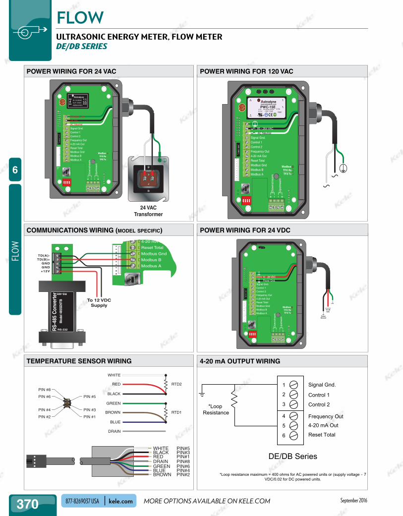
DE/DB Series
1
2
3
4
5
6
Signal Gnd.
Control 1
Control 2
Frequency Out
4-20 mA Out
Reset Total
*LoopResistance
*Loop resistance maximum = 400 ohms for AC powered units or (supply voltage – 7VDC/0.02 for DC powered units.
PIN #1
PIN #3
PIN #5
PIN #2
PIN #4
PIN #6
PIN #8RTD2
RTD1
WHITE
RED
BLACK
GREEN
BROWN
BLUE
DRAIN
WHITE BLACKRED
GREENBLUEBROWN
DRAIN
PIN#3
PIN#6
PIN#1PIN#8
PIN#4PIN#2
PIN#5
4-20 mA Out
Reset Total
Modbus Gnd
Modbus B
Modbus A
TD(A)-TD(B)+
GNDGND+12V
RS-
485
Con
vert
erM
odel
485
SD9T
B
RS-232
RS-485
To 12 VDCSupply
24 VACTransformer
Dow
nst
ream
Upst
ream
+ +- -
ModbusTFX RxTFX Tx
Signal Gnd.Control 1Control 2Frequency Out4-20 mA OutReset TotalModbus GndModbus BModbus A
1 2 3 4ON
-IN+
OU
T+O
UT−
IN: 18-36VAC
OUT: 15VDC
ASD06-24S15
TestP1
Chassis Gnd.24 VACAC Neutral
10 - 28 VDC Power Gnd.
Dow
nst
rea
m
Up
stre
am
+ +- -
ModbusTFX RxTFX Tx
1 2 3 4ON
Signal Gnd.Control 1Control 2Frequency Out4-20 mA OutReset TotalModbus GndModbus BModbus A
10 -28VDC
PowerGround
10 - 28 VDC Power Gnd.
Dow
nst
ream
Upst
ream
+ +- -
ModbusTFX RxTFX Tx
Signal Gnd.Control 1Control 2Frequency Out4-20 mA OutReset TotalModbus GndModbus BModbus A
R AC IN : 100-240VAC,50/60HzDC OUT : +15V / 0.3A
PWC-15E 0.15A
R2807
www.astrodyne.com
-Vo
+Vo
ACL
ACN strodyne
1 2 3 4ON
95 - 264 VACAC Neutral
coMMunications WirinG (model specific)
poWer WirinG For 120 VacpoWer WirinG For 24 Vac
poWer WirinG For 24 VDc
teMperature sensor WirinG
ultraSonic energy meter, flow meterDe/DB SerieS
4-20 ma output WirinG

NEW!
371
FLOWFLO
W
6
let kele source your hard-to-find options kele.com 877-826-9037 USASeptember 2016
orDerinG inForMation
accessoriesD005-0803-104 UltraLink PC software for DE/DB Meters (required accessory)D005-2117-003 USB A/B Cable, 10 ft. (3 m) for DE/DB Series Meters (required accessoryD005-2117-004 USB A/B Cable, 15 ft. (4.6 m) for DE/DB Series MetersD002-2007-005 72" stainless steel straps, 1 pair, for DTTN/DTTH, for pipes up to 20"D005-0350-300 RTD Connector Kit (required for non-standard sensors)D010-2102-010 Mounting track assembly for DTTN/DTTH transducers, for <10" pipesD010-2102-016 Mounting track assembly for DTTN/DTTH transducers, for 10" to 16" pipesD010-3000-120 RTD kit for DE Energy Meter, strap-on, 20 ft. cablesD010-3000-121 RTD kit for DE Energy Meter, strap-on, 50 ft. cablesD010-3000-122 RTD kit for DE Energy Meter, strap-on, 100 ft. cables
MODEL DESCRIPTIONDE BTU Meter
PIPE SIZEIA 1/2" ANSI pipeIB 3/4" ANSI pipeIC 1" ANSI pipeID 1 1/4" ANSI pipeIE 1 1/2" ANSI pipeIF 2" ANSI pipeIG 1/2" copperIH 3/4" copperII 1" copperIJ 1 1/4" copperIK 1 1/2" copperIL 2" copperIM 1/2" OD tubing IN 3/4" OD tubingIP 1" OD tubingIQ 1 1/4" OD tubingIR 1 1/2" OD tubingIS 2" OD tubing RZ Remote Flow Transducers (see DT, DS tables)
HNone (select for Remote Transducer Only)
A 90-264 VAC
TRANSDUCER MATERIAL/TEMPERATURE
L
N
PVC: -40 to +185˚F (-40 to +185˚C)CPVC: -40 to +250˚F (-40 to +121˚C)
POWER
C
D
20-28 VAC
11-28 VDC
KEYPAD
Y
N
Keypad
No keypad
COMMUNICATIONS
YH BACnet MSTP @ 7800 bandB BACnet MSTP
N
10/100 Base-T (EtherNet/IP, BACnet/IP, Modbus TCP/IP)
No communications
ENERGY TEMPERATURE RANGE (Separately ordered RTD kit required)
L
M
+32 to +122˚F (0 to +122˚C)
+32 to +212˚F (0 to +100˚C)
H
X
-40 to +350˚F (-40 to +177˚C)
-4 to +85˚F (-20 to +30˚C)
APPROVALS
N General safety (power supply C only)
OPTIONS
0
1
None, plugged ports
Cable Gland Kit
N None (for DB flowmeter)
DB Flowmeter
Note: Shaded selections are special order.*DT remote transducers come with 36" straps that fit pipes up to 10". (P/N D002-2007-001)
Two Remote transducers for small pipes (with “RZ” pipe size)
MODEL DESCRIPTIONDTTS Remote transducers for 1/2" to 2" pipes
PIPE SIZE*D 1/2"F 3/4"G 1"H 1 1/4"J 1 1/2"L 2"
PIPE TYPEP ANSI carbon steelC CopperT Tubing
CABLE LENGTH020 20 feet (6.1 m)050 50 feet (15 m)100 100 feet (30 m)
CABLE ARMOR OPTIONN No armorA Flexible armor
CABLE ARMOR LENGTH000 No armor020 20 feet (6.1 m)050 50 feet (15 m)100 100 feet (30 m)
Two Remote transducers for large pipes (with “RZ” pipe size)MODEL DESCRIPTION
CABLE LENGTH020 20 feet (6.1 m)050 50 feet (15 m)100 100 feet (30 m)
CABLE ARMOR OPTIONN No armorA Flexible armor
CABLE ARMOR LENGTH000 No armor020 20 feet (6.1 m)050 50 feet (15 m)100 100 feet (30 m)
OPTIONSN Normal area rating
DTTN Standard transducer for 2 1/2" to 20" pipes*DTTH High temperature transducer for 2 1/2" to 100" pipes*
DTTC High Temperature transducer for 1/2” to 2” pipesDTTL Large transducer for 22" to 100" pipes
ultraSonic energy meter, flow meterDe/DB SerieS