Ultraportable Spectrum Analyzer
15
Product Brochure Spectrum Master ™ Ultraportable Spectrum Analyzer MS2760A 9 kHz to 32, 44, 50, 70, 90, 110, 145, 170 GHz MS2762A 6 GHz to 32, 44, 50, 70, 90, 110, 145, 170 GHz
Transcript of Ultraportable Spectrum Analyzer
Product Brochure
Spectrum Master™
Ultraportable Spectrum Analyzer MS2760A 9 kHz to 32, 44, 50, 70, 90, 110, 145, 170 GHz
MS2762A 6 GHz to 32, 44, 50, 70, 90, 110, 145, 170 GHz
2
Introduction
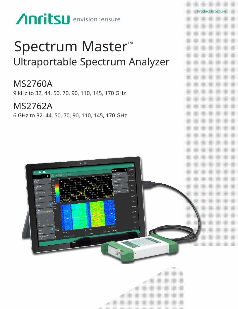
Utilizing Anritsu’s patented nonlinear transmission line (NLTL) technology, the Spectrum Master™ MS2760A and MS2762A ultraportable spectrum analyzer products deliver the best-in-class price/performance ratio unmatched by traditional benchtop instruments. This enables you to more efficiently advance your technology development and reduce your time to market. The Spectrum Master™ MS276xA series are pocket-sized, yet big on performance with leading dynamic range, sweep speed, and amplitude accuracy. The ultraportable size of these instruments enables a direct connection to almost any DUT, eliminating the need for lossy, expensive cables.
The 145 GHz and 170 GHz models are the world’s first handheld millimeter-wave spectrum analyzers to provide broadband, continuous coverage from 9 kHz to 170 GHz. These are the world’s first and only broadband spectrum analyzers that break through the 110 GHz barrier and enable research and development in the entire D band spectrum. They are perfect for advanced millimeter-wave applications like radio astronomy, automotive radar, antenna beam pattern testing, and more. The Spectrum Master™ MS2760A and MS2762A are USB-powered and controlled from a Windows-based PC, laptop, or tablet, making them uniquely flexible for use in the lab, on the manufacturing floor, or even in the field.
The Spectrum Master MS2760A models provide full broadband coverage from 9 kHz to 170 GHz with excellent dynamic range and DANL performance.
The Spectrum Master MS2762A models provide even better dynamic range and DANL performance than the Spectrum Master MS2760A models, for the most demanding sensitivity requirements, with frequency coverage starting at 6 GHz and a top frequency range of 170 GHz.
Spectrum Master MS2760A Highlights • Frequency from 9 kHz up to 170 GHz • DANL: as low as -134 dBm, 4 to 40 GHz• Dynamic Range: > 103 dB at 70 GHz
Spectrum Master MS2762A Highlights• Frequency from 6 GHz up to 170 GHz• DANL: as low as -142 dBm, 6 to 40 GHz • Dynamic Range: > 108 dB at 70 GHz
Spectrum Master MS2760A and MS2762A Highlights• Measure: Channel Power, Adjacent Channel Power, Occupied Bandwidth• Spectrum and Spectrogram Displays • Zero span• Resolution Bandwidth (RBW): 1 Hz to 3 MHz• Up to Six Spectrum Traces and Spectrogram Cursors, Three Trace Detectors, 12 Markers• External 10 MHz Frequency Reference• External TTL Trigger Input
3
Typical Applications
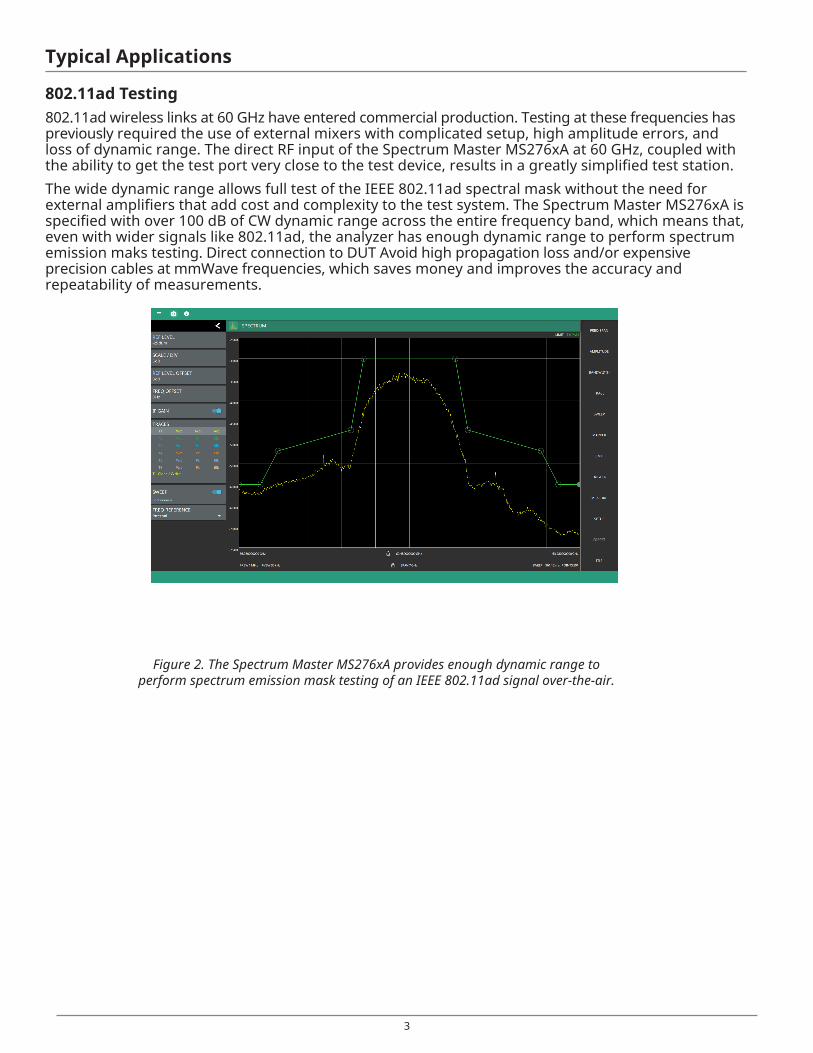
802.11ad Testing 802.11ad wireless links at 60 GHz have entered commercial production. Testing at these frequencies has previously required the use of external mixers with complicated setup, high amplitude errors, and loss of dynamic range. The direct RF input of the Spectrum Master MS276xA at 60 GHz, coupled with the ability to get the test port very close to the test device, results in a greatly simplified test station.The wide dynamic range allows full test of the IEEE 802.11ad spectral mask without the need for external amplifiers that add cost and complexity to the test system. The Spectrum Master MS276xA is specified with over 100 dB of CW dynamic range across the entire frequency band, which means that, even with wider signals like 802.11ad, the analyzer has enough dynamic range to perform spectrum emission maks testing. Direct connection to DUT Avoid high propagation loss and/or expensive precision cables at mmWave frequencies, which saves money and improves the accuracy and repeatability of measurements.
Figure 2. The Spectrum Master MS276xA provides enough dynamic range to perform spectrum emission mask testing of an IEEE 802.11ad signal over-the-air.
4
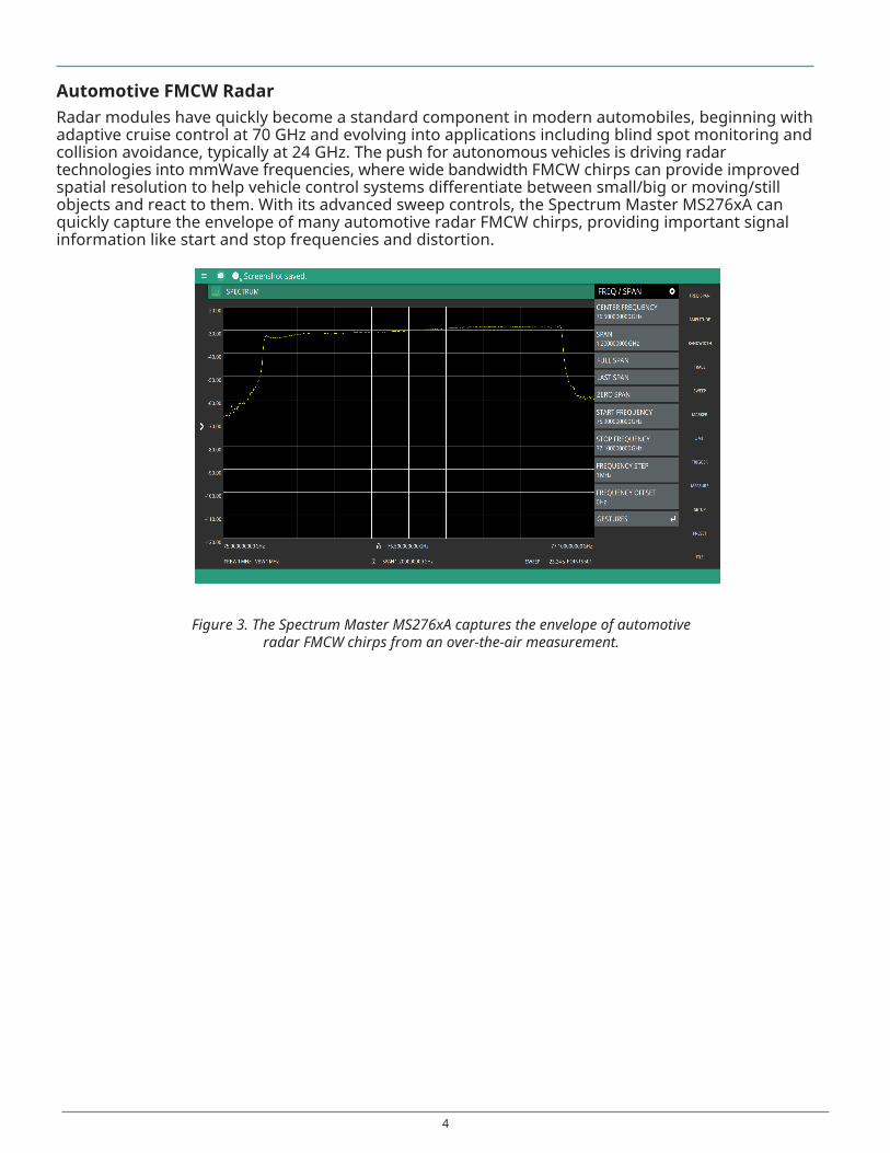
Automotive FMCW RadarRadar modules have quickly become a standard component in modern automobiles, beginning with adaptive cruise control at 70 GHz and evolving into applications including blind spot monitoring and collision avoidance, typically at 24 GHz. The push for autonomous vehicles is driving radar technologies into mmWave frequencies, where wide bandwidth FMCW chirps can provide improved spatial resolution to help vehicle control systems differentiate between small/big or moving/still objects and react to them. With its advanced sweep controls, the Spectrum Master MS276xA can quickly capture the envelope of many automotive radar FMCW chirps, providing important signal information like start and stop frequencies and distortion.
Figure 3. The Spectrum Master MS276xA captures the envelope of automotive radar FMCW chirps from an over-the-air measurement.
5
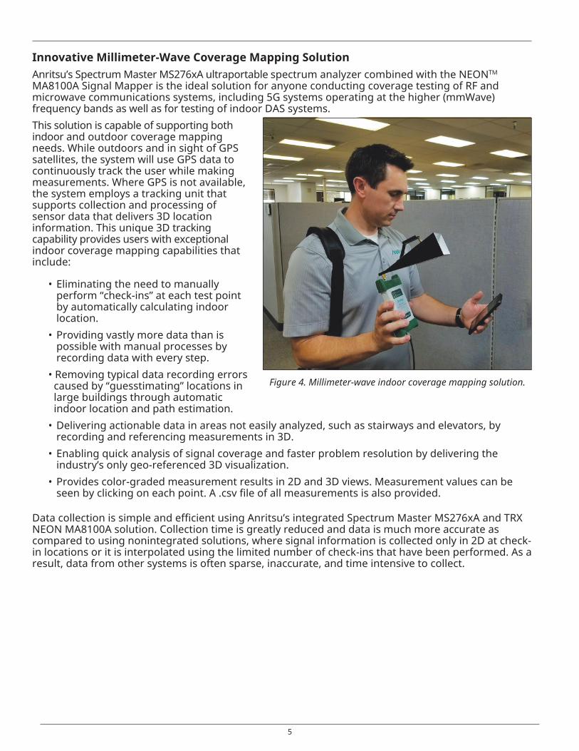
Innovative Millimeter-Wave Coverage Mapping Solution Anritsu’s Spectrum Master MS276xA ultraportable spectrum analyzer combined with the NEONTM
MA8100A Signal Mapper is the ideal solution for anyone conducting coverage testing of RF and microwave communications systems, including 5G systems operating at the higher (mmWave) frequency bands as well as for testing of indoor DAS systems.This solution is capable of supporting both indoor and outdoor coverage mapping needs. While outdoors and in sight of GPS satellites, the system will use GPS data to continuously track the user while making measurements. Where GPS is not available, the system employs a tracking unit that supports collection and processing of sensor data that delivers 3D location information. This unique 3D tracking capability provides users with exceptional indoor coverage mapping capabilities that include:
• Eliminating the need to manually perform “check-ins” at each test point by automatically calculating indoor location.
• Providing vastly more data than is possible with manual processes by recording data with every step.
• Removing typical data recording errors caused by “guesstimating” locations in large buildings through automatic indoor location and path estimation.• Delivering actionable data in areas not easily analyzed, such as stairways and elevators, by
recording and referencing measurements in 3D.• Enabling quick analysis of signal coverage and faster problem resolution by delivering the
industry’s only geo-referenced 3D visualization.• Provides color-graded measurement results in 2D and 3D views. Measurement values can be
seen by clicking on each point. A .csv file of all measurements is also provided.
Data collection is simple and efficient using Anritsu’s integrated Spectrum Master MS276xA and TRX NEON MA8100A solution. Collection time is greatly reduced and data is much more accurate as compared to using nonintegrated solutions, where signal information is collected only in 2D at check-in locations or it is interpolated using the limited number of check-ins that have been performed. As a result, data from other systems is often sparse, inaccurate, and time intensive to collect.
Figure 4. Millimeter-wave indoor coverage mapping solution.
6
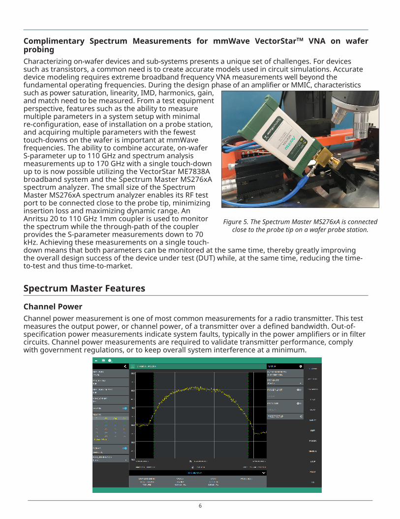
Complimentary Spectrum Measurements for mmWave VectorStarTM VNA on wafer probingCharacterizing on-wafer devices and sub-systems presents a unique set of challenges. For devices such as transistors, a common need is to create accurate models used in circuit simulations. Accurate device modeling requires extreme broadband frequency VNA measurements well beyond the fundamental operating frequencies. During the design phase of an amplifier or MMIC, characteristics such as power saturation, linearity, IMD, harmonics, gain, and match need to be measured. From a test equipment perspective, features such as the ability to measure multiple parameters in a system setup with minimal re-configuration, ease of installation on a probe station, and acquiring multiple parameters with the fewest touch-downs on the wafer is important at mmWave frequencies. The ability to combine accurate, on-wafer S-parameter up to 110 GHz and spectrum analysis measurements up to 170 GHz with a single touch-down up to is now possible utilizing the VectorStar ME7838A broadband system and the Spectrum Master MS276xA spectrum analyzer. The small size of the Spectrum Master MS276xA spectrum analyzer enables its RF test port to be connected close to the probe tip, minimizing insertion loss and maximizing dynamic range. An Anritsu 20 to 110 GHz 1mm coupler is used to monitor the spectrum while the through-path of the coupler provides the S-parameter measurements down to 70 kHz. Achieving these measurements on a single touch-down means that both parameters can be monitored at the same time, thereby greatly improving the overall design success of the device under test (DUT) while, at the same time, reducing the time-to-test and thus time-to-market.
Spectrum Master Features
Channel Power Channel power measurement is one of most common measurements for a radio transmitter. This test measures the output power, or channel power, of a transmitter over a defined bandwidth. Out-of-specification power measurements indicate system faults, typically in the power amplifiers or in filter circuits. Channel power measurements are required to validate transmitter performance, comply with government regulations, or to keep overall system interference at a minimum.
Figure 5. The Spectrum Master MS276xA is connected close to the probe tip on a wafer probe station.
7
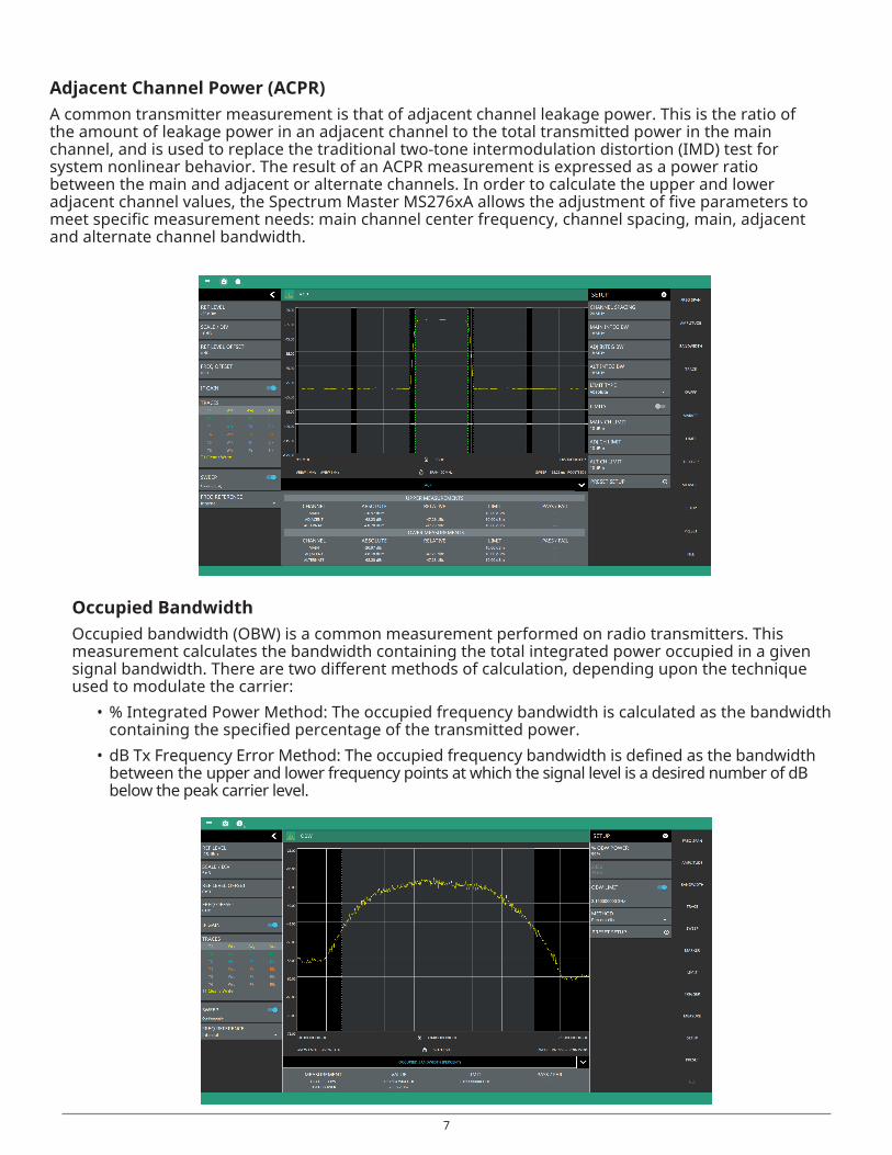
Adjacent Channel Power (ACPR)A common transmitter measurement is that of adjacent channel leakage power. This is the ratio of the amount of leakage power in an adjacent channel to the total transmitted power in the main channel, and is used to replace the traditional two-tone intermodulation distortion (IMD) test for system nonlinear behavior. The result of an ACPR measurement is expressed as a power ratio between the main and adjacent or alternate channels. In order to calculate the upper and lower adjacent channel values, the Spectrum Master MS276xA allows the adjustment of five parameters to meet specific measurement needs: main channel center frequency, channel spacing, main, adjacent and alternate channel bandwidth.
Occupied BandwidthOccupied bandwidth (OBW) is a common measurement performed on radio transmitters. This measurement calculates the bandwidth containing the total integrated power occupied in a given signal bandwidth. There are two different methods of calculation, depending upon the technique used to modulate the carrier:
• % Integrated Power Method: The occupied frequency bandwidth is calculated as the bandwidth containing the specified percentage of the transmitted power.
• dB Tx Frequency Error Method: The occupied frequency bandwidth is defined as the bandwidth between the upper and lower frequency points at which the signal level is a desired number of dB below the peak carrier level.
8
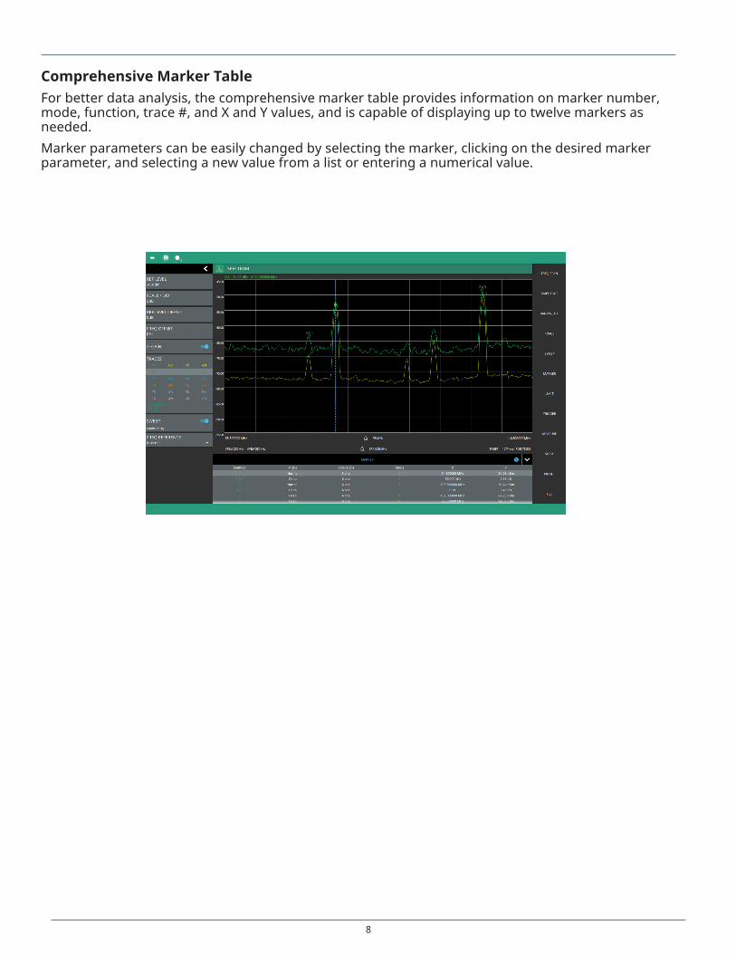
Comprehensive Marker TableFor better data analysis, the comprehensive marker table provides information on marker number, mode, function, trace #, and X and Y values, and is capable of displaying up to twelve markers as needed. Marker parameters can be easily changed by selecting the marker, clicking on the desired marker parameter, and selecting a new value from a list or entering a numerical value.
9
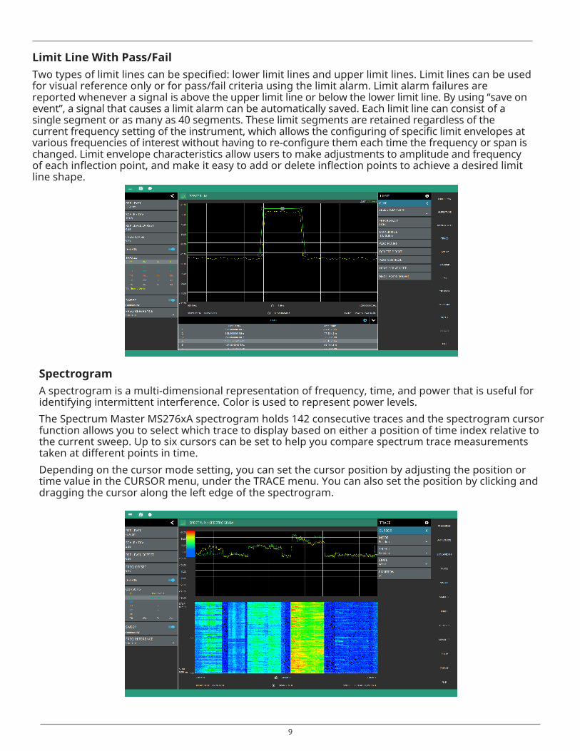
Limit Line With Pass/FailTwo types of limit lines can be specified: lower limit lines and upper limit lines. Limit lines can be used for visual reference only or for pass/fail criteria using the limit alarm. Limit alarm failures are reported whenever a signal is above the upper limit line or below the lower limit line. By using “save on event”, a signal that causes a limit alarm can be automatically saved. Each limit line can consist of a single segment or as many as 40 segments. These limit segments are retained regardless of the current frequency setting of the instrument, which allows the configuring of specific limit envelopes at various frequencies of interest without having to re-configure them each time the frequency or span is changed. Limit envelope characteristics allow users to make adjustments to amplitude and frequency of each inflection point, and make it easy to add or delete inflection points to achieve a desired limit line shape.
Spectrogram A spectrogram is a multi-dimensional representation of frequency, time, and power that is useful for identifying intermittent interference. Color is used to represent power levels. The Spectrum Master MS276xA spectrogram holds 142 consecutive traces and the spectrogram cursor function allows you to select which trace to display based on either a position of time index relative to the current sweep. Up to six cursors can be set to help you compare spectrum trace measurements taken at different points in time.Depending on the cursor mode setting, you can set the cursor position by adjusting the position or time value in the CURSOR menu, under the TRACE menu. You can also set the position by clicking and dragging the cursor along the left edge of the spectrogram.
10
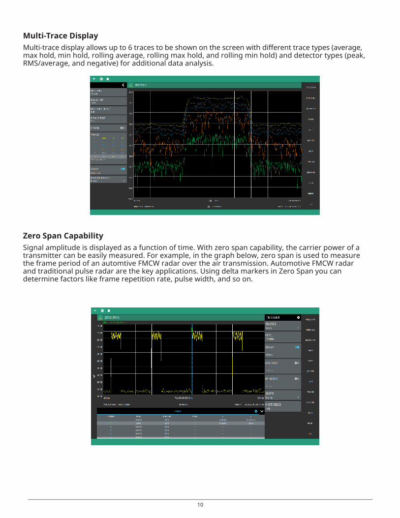
Multi-Trace Display Multi-trace display allows up to 6 traces to be shown on the screen with different trace types (average, max hold, min hold, rolling average, rolling max hold, and rolling min hold) and detector types (peak, RMS/average, and negative) for additional data analysis.
Zero Span Capability Signal amplitude is displayed as a function of time. With zero span capability, the carrier power of a transmitter can be easily measured. For example, in the graph below, zero span is used to measure the frame period of an automtive FMCW radar over the air transmission. Automotive FMCW radar and traditional pulse radar are the key applications. Using delta markers in Zero Span you can determine factors like frame repetition rate, pulse width, and so on.
11
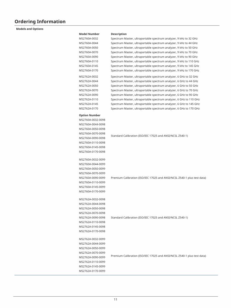
Ordering InformationModels and Options
Model Number DescriptionMS2760A-0032 Spectrum Master, ultraportable spectrum analyzer, 9 kHz to 32 GHz
MS2760A-0044 Spectrum Master, ultraportable spectrum analyzer, 9 kHz to 44 GHz
MS2760A-0050 Spectrum Master, ultraportable spectrum analyzer, 9 kHz to 50 GHz
MS2760A-0070 Spectrum Master, ultraportable spectrum analyzer, 9 kHz to 70 GHz
MS2760A-0090 Spectrum Master, ultraportable spectrum analyzer, 9 kHz to 90 GHz
MS2760A-0110 Spectrum Master, ultraportable spectrum analyzer, 9 kHz to 110 GHz
MS2760A-0145 Spectrum Master, ultraportable spectrum analyzer, 9 kHz to 145 GHz
MS2760A-0170 Spectrum Master, ultraportable spectrum analyzer, 9 kHz to 170 GHz
MS2762A-0032 Spectrum Master, ultraportable spectrum analyzer, 6 GHz to 32 GHz
MS2762A-0044 Spectrum Master, ultraportable spectrum analyzer, 6 GHz to 44 GHz
MS2762A-0050 Spectrum Master, ultraportable spectrum analyzer, 6 GHz to 50 GHz
MS2762A-0070 Spectrum Master, ultraportable spectrum analyzer, 6 GHz to 70 GHz
MS2762A-0090 Spectrum Master, ultraportable spectrum analyzer, 6 GHz to 90 GHz
MS2762A-0110 Spectrum Master, ultraportable spectrum analyzer, 6 GHz to 110 GHz
MS2762A-0145 Spectrum Master, ultraportable spectrum analyzer, 6 GHz to 145 GHz
MS2762A-0170 Spectrum Master, ultraportable spectrum analyzer, 6 GHz to 170 GHz
Option NumberMS2760A-0032-0098
Standard Calibration (ISO/IEC 17025 and ANSI/NCSL Z540-1)
MS2760A-0044-0098
MS2760A-0050-0098
MS2760A-0070-0098
MS2760A-0090-0098
MS2760A-0110-0098
MS2760A-0145-0098
MS2760A-0170-0098
MS2760A-0032-0099
MS2760A-0044-0099
MS2760A-0050-0099
MS2760A-0070-0099
MS2760A-0090-0099 Premium Calibration (ISO/IEC 17025 and ANSI/NCSL Z540-1 plus test data)
MS2760A-0110-0099
MS2760A-0145-0099
MS2760A-0170-0099
MS2762A-0032-0098
MS2762A-0044-0098
MS2762A-0050-0098
MS2762A-0070-0098
MS2762A-0090-0098 Standard Calibration (ISO/IEC 17025 and ANSI/NCSL Z540-1)
MS2762A-0110-0098
MS2762A-0145-0098
MS2762A-0170-0098
MS2762A-0032-0099
Premium Calibration (ISO/IEC 17025 and ANSI/NCSL Z540-1 plus test data)
MS2762A-0044-0099
MS2762A-0050-0099
MS2762A-0070-0099
MS2762A-0090-0099
MS2762A-0110-0099
MS2762A-0145-0099
MS2762A-0170-0099
12
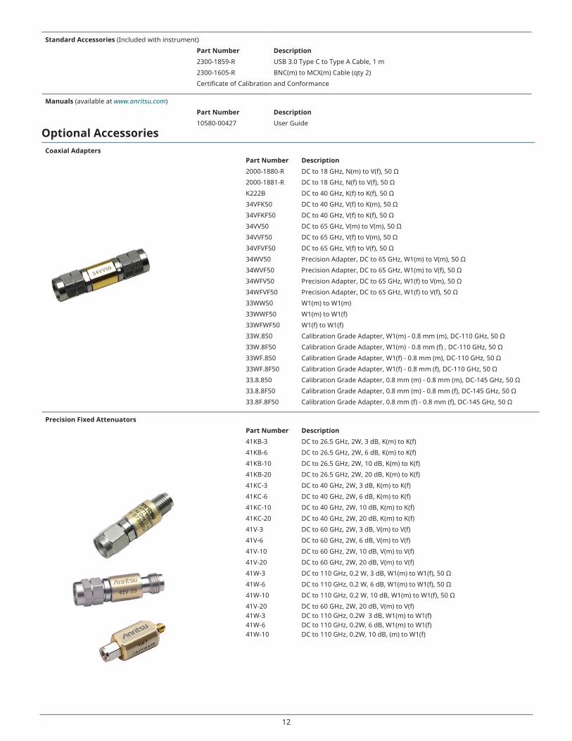
Standard Accessories (Included with instrument)
Part Number Description2300-1859-R USB 3.0 Type C to Type A Cable, 1 m
2300-1605-R BNC(m) to MCX(m) Cable (qty 2)
Certificate of Calibration and Conformance
Manuals (available at www.anritsu.com)
Part Number Description10580-00427 User Guide
Optional AccessoriesCoaxial Adapters
Part Number Description2000-1880-R DC to 18 GHz, N(m) to V(f), 50 Ω
2000-1881-R DC to 18 GHz, N(f) to V(f), 50 Ω
K222B DC to 40 GHz, K(f) to K(f), 50 Ω
34VFK50 DC to 40 GHz, V(f) to K(m), 50 Ω
34VFKF50 DC to 40 GHz, V(f) to K(f), 50 Ω
34VV50 DC to 65 GHz, V(m) to V(m), 50 Ω
34VVF50 DC to 65 GHz, V(f) to V(m), 50 Ω
34VFVF50 DC to 65 GHz, V(f) to V(f), 50 Ω
34WV50 Precision Adapter, DC to 65 GHz, W1(m) to V(m), 50 Ω
34WVF50 Precision Adapter, DC to 65 GHz, W1(m) to V(f), 50 Ω
34WFV50 Precision Adapter, DC to 65 GHz, W1(f) to V(m), 50 Ω
34WFVF50 Precision Adapter, DC to 65 GHz, W1(f) to V(f), 50 Ω
33WW50 W1(m) to W1(m)
33WWF50 W1(m) to W1(f)
33WFWF50 W1(f) to W1(f)
33W.850 Calibration Grade Adapter, W1(m) - 0.8 mm (m), DC-110 GHz, 50 Ω
33W.8F50 Calibration Grade Adapter, W1(m) - 0.8 mm (f) , DC-110 GHz, 50 Ω
33WF.850 Calibration Grade Adapter, W1(f) - 0.8 mm (m), DC-110 GHz, 50 Ω
33WF.8F50 Calibration Grade Adapter, W1(f) - 0.8 mm (f), DC-110 GHz, 50 Ω
33.8.850 Calibration Grade Adapter, 0.8 mm (m) - 0.8 mm (m), DC-145 GHz, 50 Ω
33.8.8F50 Calibration Grade Adapter, 0.8 mm (m) - 0.8 mm (f), DC-145 GHz, 50 Ω
33.8F.8F50 Calibration Grade Adapter, 0.8 mm (f) - 0.8 mm (f), DC-145 GHz, 50 Ω
Precision Fixed AttenuatorsPart Number Description41KB-3 DC to 26.5 GHz, 2W, 3 dB, K(m) to K(f)
41KB-6 DC to 26.5 GHz, 2W, 6 dB, K(m) to K(f)
41KB-10 DC to 26.5 GHz, 2W, 10 dB, K(m) to K(f)
41KB-20 DC to 26.5 GHz, 2W, 20 dB, K(m) to K(f)
41KC-3 DC to 40 GHz, 2W, 3 dB, K(m) to K(f)
41KC-6 DC to 40 GHz, 2W, 6 dB, K(m) to K(f)
41KC-10 DC to 40 GHz, 2W, 10 dB, K(m) to K(f)
41KC-20 DC to 40 GHz, 2W, 20 dB, K(m) to K(f)
41V-3 DC to 60 GHz, 2W, 3 dB, V(m) to V(f)
41V-6 DC to 60 GHz, 2W, 6 dB, V(m) to V(f)
41V-10 DC to 60 GHz, 2W, 10 dB, V(m) to V(f)
41V-20 DC to 60 GHz, 2W, 20 dB, V(m) to V(f)
41W-3 DC to 110 GHz, 0.2 W, 3 dB, W1(m) to W1(f), 50 Ω
41W-6 DC to 110 GHz, 0.2 W, 6 dB, W1(m) to W1(f), 50 Ω
41W-10 DC to 110 GHz, 0.2 W, 10 dB, W1(m) to W1(f), 50 Ω
41V-20 41W-341W-641W-10
DC to 60 GHz, 2W, 20 dB, V(m) to V(f)DC to 110 GHz, 0.2W 3 dB, W1(m) to W1(f)DC to 110 GHz, 0.2W, 6 dB, W1(m) to W1(f)DC to 110 GHz, 0.2W, 10 dB, (m) to W1(f)
13
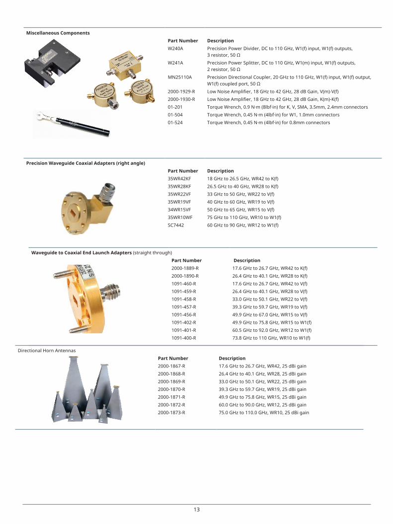
Miscellaneous ComponentsPart Number DescriptionW240A Precision Power Divider, DC to 110 GHz, W1(f) input, W1(f) outputs,
3 resistor, 50 Ω
W241A Precision Power Splitter, DC to 110 GHz, W1(m) input, W1(f) outputs,2 resistor, 50 Ω
MN25110A Precision Directional Coupler, 20 GHz to 110 GHz, W1(f) input, W1(f) output,W1(f) coupled port, 50 Ω
2000-1929-R Low Noise Amplifier, 18 GHz to 42 GHz, 28 dB Gain, V(m)-V(f)
2000-1930-R Low Noise Amplifier, 18 GHz to 42 GHz, 28 dB Gain, K(m)-K(f)
01-201 Torque Wrench, 0.9 N·m (8lbf·in) for K, V, SMA, 3.5mm, 2.4mm connectors
01-504 Torque Wrench, 0.45 N·m (4lbf·in) for W1, 1.0mm connectors
01-524 Torque Wrench, 0.45 N·m (4lbf·in) for 0.8mm connectors
Precision Waveguide Coaxial Adapters (right angle)Part Number Description35WR42KF 18 GHz to 26.5 GHz, WR42 to K(f)
35WR28KF 26.5 GHz to 40 GHz, WR28 to K(f)
35WR22VF 33 GHz to 50 GHz, WR22 to V(f)
35WR19VF 40 GHz to 60 GHz, WR19 to V(f)
34WR15VF 50 GHz to 65 GHz, WR15 to V(f)
35WR10WF 75 GHz to 110 GHz, WR10 to W1(f)
SC7442 60 GHz to 90 GHz, WR12 to W1(f)
Waveguide to Coaxial End Launch Adapters (straight through)
Part Number Description2000-1889-R 17.6 GHz to 26.7 GHz, WR42 to K(f)
2000-1890-R 26.4 GHz to 40.1 GHz, WR28 to K(f)
1091-460-R 17.6 GHz to 26.7 GHz, WR42 to V(f)
1091-459-R 26.4 GHz to 40.1 GHz, WR28 to V(f)
1091-458-R 33.0 GHz to 50.1 GHz, WR22 to V(f)
1091-457-R 39.3 GHz to 59.7 GHz, WR19 to V(f)
1091-456-R 49.9 GHz to 67.0 GHz, WR15 to V(f)
1091-402-R 49.9 GHz to 75.8 GHz, WR15 to W1(f)
1091-401-R 60.5 GHz to 92.0 GHz, WR12 to W1(f)
1091-400-R 73.8 GHz to 110 GHz, WR10 to W1(f)
Directional Horn Antennas
Part Number Description2000-1867-R 17.6 GHz to 26.7 GHz, WR42, 25 dBi gain
2000-1868-R 26.4 GHz to 40.1 GHz, WR28, 25 dBi gain
2000-1869-R 33.0 GHz to 50.1 GHz, WR22, 25 dBi gain
2000-1870-R 39.3 GHz to 59.7 GHz, WR19, 25 dBi gain
2000-1871-R 49.9 GHz to 75.8 GHz, WR15, 25 dBi gain
2000-1872-R 60.0 GHz to 90.0 GHz, WR12, 25 dBi gain
2000-1873-R 75.0 GHz to 110.0 GHz, WR10, 25 dBi gain
14
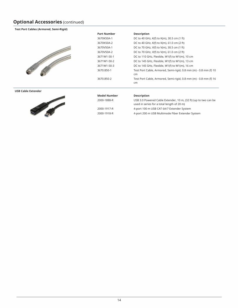
Optional Accessories (continued)
Test Port Cables (Armored, Semi-Rigid)Part Number Description3670K50A-1 DC to 40 GHz, K(f) to K(m), 30.5 cm (1 ft)
3670K50A-2 DC to 40 GHz, K(f) to K(m), 61.0 cm (2 ft)
3670V50A-1 DC to 70 GHz, V(f) to V(m), 30.5 cm (1 ft)
3670V50A-2 DC to 70 GHz, V(f) to V(m), 61.0 cm (2 ft)
3671W1-50-1 DC to 110 GHz, Flexible, W1(f) to W1(m), 10 cm
3671W1-50-2 DC to 145 GHz, Flexible, W1(f) to W1(m), 13 cm
3671W1-50-3 DC to 145 GHz, Flexible, W1(f) to W1(m), 16 cm
3670.850-1 Test Port Cable, Armored, Semi-rigid, 0.8 mm (m) - 0.8 mm (f) 10 cm
3670.850-2 Test Port Cable, Armored, Semi-rigid, 0.8 mm (m) - 0.8 mm (f) 16 cm
USB Cable ExtenderModel Number Description2000-1888-R USB 3.0 Powered Cable Extender, 10 m, (32 ft) (up to two can be
used in series for a total length of 20 m)
2000-1917-R 4-port 100 m USB CAT 6A/7 Extender System
2000-1918-R 4-port 200 m USB Multimode Fiber Extender System
® Anritsu All trademarks are registered trademarks of their respective owners. Data subject to change without notice. For the most recent specifications visit: www.anritsu.com
11410-01054, Rev. D Printed in United States 2019-09©2019 Anritsu Company. All Rights Reserved.
Anritsu utilizes recycled paper and environmentally conscious inks and toner.
• United States Anritsu Americas Sales Company50 Century Parkway, Suite 190,Allen, TX, 75013 U.S.A. Phone: +1-800-Anritsu (1-800-267-4878)
• Canada Anritsu Electronics Ltd.700 Silver Seven Road, Suite 120, Kanata, Ontario K2V 1C3, Canada Phone: +1-613-591-2003 Fax: +1-613-591-1006
• Brazil Anritsu Electrônica Ltda.Praça Amadeu Amaral, 27 - 1 Andar 01327-010 - Bela Vista - Sao Paulo - SP - Brazil Phone: +55-11-3283-2511 Fax: +55-11-3288-6940
• Mexico Anritsu Company, S.A. de C.V.Av. Ejército Nacional No. 579 Piso 9, Col. Granada 11520 México, D.F., México Phone: +52-55-1101-2370 Fax: +52-55-5254-3147
• United Kingdom Anritsu EMEA Ltd.200 Capability Green, Luton, Bedfordshire LU1 3LU, U.K. Phone: +44-1582-433280 Fax: +44-1582-731303
• France Anritsu S.A.12 avenue du Québec, Batiment Iris 1-Silic 612, 91140 Villebon-sur-Yvette, France Phone: +33-1-60-92-15-50 Fax: +33-1-64-46-10-65
• Germany Anritsu GmbHNemetschek Haus, Konrad-Zuse-Platz 1 81829 München, Germany Phone: +49-89-442308-0 Fax: +49-89-442308-55
• Italy Anritsu S.r.l.Via Elio Vittorini 129, 00144 Roma Italy Phone: +39-06-509-9711 Fax: +39-06-502-2425
• Sweden Anritsu ABKistagången 20B, 164 40 KISTA, Sweden Phone: +46-8-534-707-00 Fax: +46-8-534-707-30
• Finland Anritsu ABTeknobulevardi 3-5, FI-01530 VANTAA, Finland Phone: +358-20-741-8100 Fax: +358-20-741-8111
• Denmark Anritsu A/SKay Fiskers Plads 9, 2300 Copenhagen S, Denmark Phone: +45-7211-2200 Fax: +45-7211-2210
• Russia Anritsu EMEA Ltd. Representation Office in RussiaTverskaya str. 16/2, bld. 1, 7th floor. Moscow, 125009, Russia Phone: +7-495-363-1694 Fax: +7-495-935-8962
• Spain Anritsu EMEA Ltd. Representation Office in SpainEdificio Cuzco IV, Po. de la Castellana, 141, Pta. 5 28046, Madrid, Spain Phone: +34-915-726-761 Fax: +34-915-726-621
• United Arab Emirates Anritsu EMEA Ltd. Dubai Liaison OfficeP O Box 500413 - Dubai Internet City Al Thuraya Building, Tower 1, Suite 701, 7th floor Dubai, United Arab Emirates Phone: +971-4-3670352 Fax: +971-4-3688460
• India Anritsu India Pvt Ltd.2nd & 3rd Floor, #837/1, Binnamangla 1st Stage, Indiranagar, 100ft Road, Bangalore - 560038, India Phone: +91-80-4058-1300 Fax: +91-80-4058-1301
• Singapore Anritsu Pte. Ltd.11 Chang Charn Road, #04-01, Shriro House Singapore 159640 Phone: +65-6282-2400 Fax: +65-6282-2533
• P. R. China (Shanghai) Anritsu (China) Co., Ltd.27th Floor, Tower A, New Caohejing International Business Center No. 391 Gui Ping Road Shanghai, Xu Hui Di District, Shanghai 200233, P.R. China Phone: +86-21-6237-0898 Fax: +86-21-6237-0899
• P. R. China (Hong Kong) Anritsu Company Ltd.Unit 1006-7, 10/F., Greenfield Tower, Concordia Plaza, No. 1 Science Museum Road, Tsim Sha Tsui East, Kowloon, Hong Kong, P. R. China Phone: +852-2301-4980 Fax: +852-2301-3545
• Japan Anritsu Corporation8-5, Tamura-cho, Atsugi-shi, Kanagawa, 243-0016 Japan Phone: +81-46-296-6509 Fax: +81-46-225-8352
• Korea Anritsu Corporation, Ltd.5FL, 235 Pangyoyeok-ro, Bundang-gu, Seongnam-si, Gyeonggi-do, 13494 Korea Phone: +82-31-696-7750 Fax: +82-31-696-7751
• Australia Anritsu Pty Ltd.Unit 20, 21-35 Ricketts Road, Mount Waverley, Victoria 3149, Australia Phone: +61-3-9558-8177 Fax: +61-3-9558-8255
• Taiwan Anritsu Company Inc.7F, No. 316, Sec. 1, Neihu Rd., Taipei 114, Taiwan Phone: +886-2-8751-1816 Fax: +886-2-8751-1817
Specifications are subject to change without notice.