Site MasterTM Cable and Antenna Analyzer with Spectrum ......Spectrum Analyzer Verification 2-5...
80
Maintenance Manual Site Master TM Cable and Antenna Analyzer with Spectrum Analyzer S331E, 2 MHz to 4 GHz S332E, 2 MHz to 4 GHz, Spectrum Analyzer, 9 kHz to 4 GHz S361E, 2 MHz to 6 GHz S362E, 2 MHz to 6 GHz, Spectrum Analyzer, 9 kHz to 6 GHz P/N: 10580-00253 Revision K Published: August 2017 Copyright 2017 Anritsu Company Anritsu Company 490 Jarvis Drive Morgan Hill, CA 95037-2809 USA http://www.anritsu.com
Transcript of Site MasterTM Cable and Antenna Analyzer with Spectrum ......Spectrum Analyzer Verification 2-5...

Maintenance Manual
Site MasterTM
Cable and Antenna Analyzerwith Spectrum AnalyzerS331E, 2 MHz to 4 GHzS332E, 2 MHz to 4 GHz, Spectrum Analyzer, 9 kHz to 4 GHzS361E, 2 MHz to 6 GHzS362E, 2 MHz to 6 GHz, Spectrum Analyzer, 9 kHz to 6 GHz
P/N: 10580-00253Revision K
Published: August 2017Copyright 2017 Anritsu Company
Anritsu Company490 Jarvis DriveMorgan Hill, CA 95037-2809USAhttp://www.anritsu.com


S3xxE MM PN: 10580-00253 Rev. K Contents-1
Table of Contents
Chapter 1—General Information
1-1 Introduction . . . . . . . . . . . . . . . . . . . . . . . . . . . . . . . . . . . . . . . . . . . . . . . . . . . . . . . . . . . . . . . . 1-1
1-2 Contacting Anritsu . . . . . . . . . . . . . . . . . . . . . . . . . . . . . . . . . . . . . . . . . . . . . . . . . . . . . . . . . . 1-1
1-3 Product Information, Compliance, and Safety . . . . . . . . . . . . . . . . . . . . . . . . . . . . . . . . . . . . . 1-1
1-4 Recommended Test Equipment . . . . . . . . . . . . . . . . . . . . . . . . . . . . . . . . . . . . . . . . . . . . . . . . 1-2
1-5 Replaceable Parts . . . . . . . . . . . . . . . . . . . . . . . . . . . . . . . . . . . . . . . . . . . . . . . . . . . . . . . . . . 1-4
Chapter 2—Spectrum Analyzer Verification
2-1 Frequency Accuracy Verification and Adjustment . . . . . . . . . . . . . . . . . . . . . . . . . . . . . . . . . . 2-1
2-2 Single Side Band (SSB) Phase Noise Verification . . . . . . . . . . . . . . . . . . . . . . . . . . . . . . . . . . 2-3
2-3 Spurious Response (Second Harmonic Distortion) Verification . . . . . . . . . . . . . . . . . . . . . . . . 2-4
2-4 Resolution Bandwidth Accuracy Verification . . . . . . . . . . . . . . . . . . . . . . . . . . . . . . . . . . . . . . 2-6RBW Test . . . . . . . . . . . . . . . . . . . . . . . . . . . . . . . . . . . . . . . . . . . . . . . . . . . . . . . . . . . . . . 2-6
2-5 Spectrum Analyzer Absolute Amplitude Accuracy Verification. . . . . . . . . . . . . . . . . . . . . . . . . 2-750 MHz Amplitude Accuracy Verification. . . . . . . . . . . . . . . . . . . . . . . . . . . . . . . . . . . . . . . 2-7Amplitude Accuracy Across Frequency Verification . . . . . . . . . . . . . . . . . . . . . . . . . . . . . 2-10
2-6 Residual Spurious Response Verification. . . . . . . . . . . . . . . . . . . . . . . . . . . . . . . . . . . . . . . . 2-14Residual Spurious Response Test with Preamp Off . . . . . . . . . . . . . . . . . . . . . . . . . . . . . 2-14Residual Spurious Response Test with Preamp On . . . . . . . . . . . . . . . . . . . . . . . . . . . . . 2-15
2-7 Displayed Average Noise Level (DANL). . . . . . . . . . . . . . . . . . . . . . . . . . . . . . . . . . . . . . . . . 2-16
2-8 Third Order Intercept (TOI) Verification . . . . . . . . . . . . . . . . . . . . . . . . . . . . . . . . . . . . . . . . . 2-18
Chapter 3—Cable and Antenna Analyzer Verification
3-1 Frequency Accuracy Verification . . . . . . . . . . . . . . . . . . . . . . . . . . . . . . . . . . . . . . . . . . . . . . . 3-1
3-2 Return Loss Accuracy Verification . . . . . . . . . . . . . . . . . . . . . . . . . . . . . . . . . . . . . . . . . . . . . . 3-2
Chapter 4—Option Verification
4-1 Introduction . . . . . . . . . . . . . . . . . . . . . . . . . . . . . . . . . . . . . . . . . . . . . . . . . . . . . . . . . . . . . . . . 4-1
4-2 Option 10, Bias Tee Verification . . . . . . . . . . . . . . . . . . . . . . . . . . . . . . . . . . . . . . . . . . . . . . . . 4-1Low Current Test Verification . . . . . . . . . . . . . . . . . . . . . . . . . . . . . . . . . . . . . . . . . . . . . . . 4-1High Current Test Verification . . . . . . . . . . . . . . . . . . . . . . . . . . . . . . . . . . . . . . . . . . . . . . . 4-2Fault Verification . . . . . . . . . . . . . . . . . . . . . . . . . . . . . . . . . . . . . . . . . . . . . . . . . . . . . . . . . 4-3
4-3 Option 21, Transmission Measurement, System Dynamic Range . . . . . . . . . . . . . . . . . . . . . . 4-4
4-4 Option 29, Power Meter Level Accuracy . . . . . . . . . . . . . . . . . . . . . . . . . . . . . . . . . . . . . . . . . 4-5
4-5 Option 31, GPS Verification . . . . . . . . . . . . . . . . . . . . . . . . . . . . . . . . . . . . . . . . . . . . . . . . . . . 4-7Frequency Accuracy Verification (Only for models S332E and S362E) . . . . . . . . . . . . . . . 4-7GPS Antenna Bias Tee Verification. . . . . . . . . . . . . . . . . . . . . . . . . . . . . . . . . . . . . . . . . . . 4-8
Chapter 5—Battery Information
5-1 General Information . . . . . . . . . . . . . . . . . . . . . . . . . . . . . . . . . . . . . . . . . . . . . . . . . . . . . . . . . 5-1
5-2 Battery Pack Removal and Replacement . . . . . . . . . . . . . . . . . . . . . . . . . . . . . . . . . . . . . . . . 5-2

Contents-2 PN: 10580-00253 Rev. K S3xxE MM
Table of Contents (Continued)
Chapter 6—Assembly Replacement
6-1 Opening the Site Master Case . . . . . . . . . . . . . . . . . . . . . . . . . . . . . . . . . . . . . . . . . . . . . . . . . 6-1
6-2 PCB Assembly Removal. . . . . . . . . . . . . . . . . . . . . . . . . . . . . . . . . . . . . . . . . . . . . . . . . . . . . . 6-3
6-3 SPA Assembly Replacement . . . . . . . . . . . . . . . . . . . . . . . . . . . . . . . . . . . . . . . . . . . . . . . . . . 6-4
6-4 SPA and MB/VNA N Connector Replacement . . . . . . . . . . . . . . . . . . . . . . . . . . . . . . . . . . . . . 6-5
6-5 GPS (Opt. 31) Replacement . . . . . . . . . . . . . . . . . . . . . . . . . . . . . . . . . . . . . . . . . . . . . . . . . . . 6-6
6-6 Option Assembly Replacement. . . . . . . . . . . . . . . . . . . . . . . . . . . . . . . . . . . . . . . . . . . . . . . . . 6-7
6-7 Motherboard/VNA Assembly Replacement . . . . . . . . . . . . . . . . . . . . . . . . . . . . . . . . . . . . . . . 6-7
6-8 Fan Assembly Replacement . . . . . . . . . . . . . . . . . . . . . . . . . . . . . . . . . . . . . . . . . . . . . . . . . . 6-8
6-9 LCD Assembly Replacement . . . . . . . . . . . . . . . . . . . . . . . . . . . . . . . . . . . . . . . . . . . . . . . . . . 6-9
6-10 LCD Backlight PCB Removal and Replacement . . . . . . . . . . . . . . . . . . . . . . . . . . . . . . . . . . 6-11
6-11 Keypad and Keypad PCB Replacement . . . . . . . . . . . . . . . . . . . . . . . . . . . . . . . . . . . . . . . . 6-12
6-12 Touch Screen Replacement . . . . . . . . . . . . . . . . . . . . . . . . . . . . . . . . . . . . . . . . . . . . . . . . . 6-13
Chapter 7—Troubleshooting
7-1 Introduction . . . . . . . . . . . . . . . . . . . . . . . . . . . . . . . . . . . . . . . . . . . . . . . . . . . . . . . . . . . . . . . . 7-1
7-2 Turn-on Problems . . . . . . . . . . . . . . . . . . . . . . . . . . . . . . . . . . . . . . . . . . . . . . . . . . . . . . . . . . . 7-1
7-3 Other Problems. . . . . . . . . . . . . . . . . . . . . . . . . . . . . . . . . . . . . . . . . . . . . . . . . . . . . . . . . . . . . 7-2
Appendix A—Test Records
A-1 Test Records for Spectrum Analyzer Verification . . . . . . . . . . . . . . . . . . . . . . . . . . . . . . . . . . A-2
A-2 Test Records for Cable and Antenna Analyzer Verification . . . . . . . . . . . . . . . . . . . . . . . . . . A-12
A-3 Test Records for Options Verification . . . . . . . . . . . . . . . . . . . . . . . . . . . . . . . . . . . . . . . . . . . A-13

S3xxE MM PN: 10580-00253 Rev. K 1-1
Chapter 1 — General Information
1-1 Introduction This manual provides maintenance instructions for Anritsu Site Master Models S331E, S332E, S361E and S362E. The manual includes:
• General information in this chapter, including:
• Lists of necessary test equipment to perform verification testing (Table 1-1, Table 1-2, and Table 1-3)
• Replaceable parts list (Table 1-4)
• Performance verification procedures:
• Chapter 2, “Spectrum Analyzer Verification”
• Chapter 3, “Cable and Antenna Analyzer Verification”
• Chapter 4, “Option Verification”
• Battery pack information (Chapter 5, “Battery Information”)
• Parts replacement procedures (Chapter 6, “Assembly Replacement”)
• Blank test records are included in Appendix A.
• Copy the blank test records from Appendix A and use them to record measured values. These test records form a record of the performance of the instrument. Anritsu recommends that you make a copy of the blank test records to document the measurements each time a Performance Verification is performed. Continuing to document this process each time it is performed provides a detailed history of instrument’s performance, allowing trends to be observed.
Familiarity with the basic operation of the front panel keys (for example, how to change measurement mode, preset the unit, or the meaning of soft key or submenu) is assumed.
1-2 Contacting AnritsuTo contact Anritsu, visit the following URL and select the services in your region:http://www.anritsu.com/contact-us.
1-3 Product Information, Compliance, and SafetyRead the Handheld Instruments Product Information, Compliance, and Safety Guide (PN: 10100-00065) for important safety, legal, and regulatory notices before operating the equipment. For additional information and literature covering your product, visit the product page of your instrument and select the Library tab.
Caution Before making any measurement, verify that all equipment has warmed up for at least 30 minutes.

1-4 Recommended Test Equipment General Information
1-2 PN: 10580-00253 Rev. K S3xxE MM
1-4 Recommended Test EquipmentThe following test equipment is recommended for use in testing and maintaining Anritsu Site Master Model S3xxE. Table 1-1 is a list of test equipment that is required for verifying the Spectrum Analyzer functions. Table 1-2 is a list of test equipment that is required for verifying the Cable and Antenna Analyzer. Table 1-3 is a list of test equipment that is required for verifying the functions of installed options.
a. MG3692A models require Option 15 to achieve power of +16 dBm at 3.5 GHz. MG3692B models do not require Option 15 to achieve power of +16 dBm at 3.5 GHz.
Table 1-1. Test Equipment Required for Verifying Spectrum Analyzer Functions
Instrument Critical SpecificationRecommended
Manufacturer/Model
Synthesized Signal Generator Frequency: 0.1 Hz to 20 GHz, Power Output: +16 dBm, Step attenuator installed
Anritsu Model MG3692A/B/C (Qty 2) with Options 2A, 3, 4, 22, 15xa
Power Meter Power Range: –70 dBm to +20 dBm Anritsu Model ML2438A
Power Sensor Frequency: 10 MHz to 18 GHzPower Range: –67 dB to +20 dB
Anritsu Model MA2442D (Qty 2)
Frequency Reference Frequency: 10 MHz Symmetricom RubiSource T&M
Fixed Attenuator 10 dB Attenuation Aeroflex/Weinschel Model 44-10
Fixed Attenuator 2 dB Attenuation Aeroflex/Weinschel Model 44-2 (Qty 2)
Fixed Attenuator 6 dB Attenuation Aeroflex/Weinschel Model 44-6 (Qty 2)
Fixed Attenuator 20 dB Attenuation Aeroflex/Weinschel Model 44-20 (Qty 2)
Low Pass Filter 50 MHz Low Pass Filter Anritsu Model 1030-96
Power Splitter Frequency: DC to 18 GHz Aeroflex/Weinschel Model 1870A
Adapter Frequency: DC to 20 GHzN(m) to N(m), 50 ohm
Anritsu Model 34NN50A
Adapter Frequency: DC to 20 GHzN(m) to N(m), 50 ohm
Anritsu Model 34RKNF50
50 ohm Termination Frequency: DC to 18 GHz Anritsu Model 28N50-2
RF Coaxial Cable Frequency: DC to 18 GHzN(m) to N(m), 50 ohm
Anritsu Model 15NN50-1.5C
Coaxial Cable BNC(m) to BNC(m), 50 ohm Anritsu Model 2000-1627-R
General Information 1-4 Recommended Test Equipment
S3xxE MM PN: 10580-00253 Rev. K 1-3
Table 1-2. Test Equipment Required for Cable and Antenna Analyzer Verification
Instrument Critical Specification Recommended Manufacturer/Model
Frequency Counter Frequency: 2 GHz Anritsu Model MF2412B
Open/Short Frequency: DC to 18 GHz Anritsu Model 22N50
Termination Frequency: DC to 18 GHzReturn Loss: 40 dB min.
Anritsu Model 28N50-2
RF Coaxial Cable Frequency: DC to 18 GHz N(m) to N(f), 50 ohm
Anritsu Model 15NN50-1.5C
6 dB Offset Termination Frequency: DC to 6.0 GHz Anritsu Model SC7424
20 dB Offset Termination Frequency: DC to 6.0 GHz Anritsu Model SC7423
Table 1-3. Test Equipment Required for Verifying Options
Instrument Critical Specification Recommended Manufacturer/Model
Termination Frequency: DC to 18 GHzReturn Loss: 40 dB min.
Anritsu Model 28N50-2
Termination Frequency: DC to 18 GHzReturn Loss: 40 dB min.
Anritsu Model 28NF50-2
Adapter 40 ohm Load Anritsu Model T2904
Adapter 78 ohm Load Anritsu Model T3536
Adapter 105 ohm Load Anritsu Model T3377
Adapter SMA to BNC(f) Pomona 4290 or equivalent
Adapter GPS Terminator Amphenol B1004A1-ND3G-93R-0.05-1W or equivalent
Adapter Frequency: DC to 20 GHz N(m) to N(m), 50 ohm
Anritsu Model 34NN50A
Adapter Frequency: DC to 20 GHz K(m) to N(f), 50 ohm
Anritsu Model 34RKNF50
GPS Antenna Anritsu 2000-1528-R
Coaxial Cable Frequency: DC to 18 GHz N(m) to N(m), 50 ohm
Anritsu Model 15NN50-1.5C
Coaxial Cable BNC(m) to BNC(m), 50 ohm Any (Qty 2) Anritsu Model 2000-1627-R
Synthesized Signal Source Frequency: 0.1 Hz to 20 GHzPower Output to +13 dBm
Anritsu Model MG3692A or B with Options 2A, 4, 22, 15a
a. Option 15 is required for MG3692A models to achieve power of +13 dBm. MG3692B models do not require Option 15.
Power Meter Power Range: −70 to +20 dBm Anritsu Dual Channel Model ML2438A
Power Sensor Frequency: 10 MHz to 18 GHzPower Range: –67 to +20 dB
Anritsu Model MA2442D (quantity 2)
Fixed Attenuator 10 dB Attenuation Aeroflex/Weinschel Model 44-10
Power Splitter Frequency: DC to 18 GHz Aeroflex/Weinschel Model 1870A
Frequency Reference Frequency: 10 MHz Symmetricom Model RubiSource T&M

1-5 Replaceable Parts General Information
1-4 PN: 10580-00253 Rev. K S3xxE MM
1-5 Replaceable Parts
Table 1-4. List of Replaceable Parts (1 of 3)
Part Number Description
ND70931<R> S331E MB/VNA PCB Assembly (units without Option 21)a s/n < 1128048 and 1128247, 1129004
ND73215<R> S331E MB/VNA PCB Assembly (units without Option 21)a s/n > 1128047 except 1128247, 1129004, and s/n < 1226201, plus some additional units per Service Note S3xxE-035
ND75282<R> S331E MB/VNA PCB Assembly with Locking connector (units without Option 21)a
1233006 < s/n < 1608000, and some additional units per Service Note S3xxE-035
3-ND82168<R> S331E MB/VNA PCB Assembly(units without Option 21)a s/n > 1608000
ND70932<R> S331E MB/VNA PCB Assembly (units with Option 21)a s/n < 1123047 and 1123058
ND73217<R> S331E MB/VNA PCB Assembly (units with Option 21)a s/n > 1123046 except 1123058, and s/n < 1226201, plus some additional units per Service Note S3xxE-035
ND75284<R> S331E MB/VNA PCB Assembly with Locking connector (units with Option 21)a 1233006 < s/n < 1608000, plus some additional units per Service Note S3xxE-035
3-ND82169<R> S331E MB/VNA PCB Assembly(units with Option 21)a s/n > 1608000
ND70929<R> S361E MB/VNA PCB Assembly (units without Option 21)a s/n < 1128183 except 1127057 and 1125052
ND73216<R> S361E MB/VNA PCB Assembly (units without Option 21)a s/n > 1128182 and also 1127057, 1125052, and s/n < 1229073, except for 1228080, 1228175, 1229063
ND75283<R> S361E MB/VNA PCB Assembly with Locking connector (units without Option 21)a 1229072 < s/n < 1606000, and also 1228080, 1228175, 1229063
3-ND82170<R> S361E MB/VNA PCB Assembly(units without Option 21)a s/n > 1606000
ND70933<R> S361E MB/VNA PCB Assembly (units with Option 21)a s/n < 1128183 except 1127057 and 1125052
ND73218<R> S361E MB/VNA PCB Assembly (units with Option 21)a s/n > 1128182 and 1127057, 1125052, and s/n < 1229073, except for 1228080, 1228175, 1229063
ND75285<R> S361E MB/VNA PCB Assembly with Locking connector (units with Option 21)a 1229072 < s/n < 1606000, and also 1228080, 1228175, 1229063
3-ND82171<R> S361E MB/VNA PCB Assembly(units with Option 21)a s/n > 1606000
ND70934<R> S332E MB/VNA PCB Assemblya s/n < 1124046 and 1126145
ND73219<R> S332E MB/VNA PCB Assemblya s/n > 1124045 except 1126145 and s/n < 1227030, plus some additional units per Service Note S3xxE-035
ND75286<R> S332E MB/VNA PCB Assembly with Locking connectora 1230095 < s/n < 1606000, and some below s/n 1230095 per Service Note S3xxE-035
3-ND82172<R> S332E MB/VNA PCB Assemblya s/n > 1606000
ND70936<R> S362E MB/VNA PCB Assemblya s/n < 1125034
ND73220<R> S362E MB/VNA PCB Assemblya 1125033 < s/n < 1230104, except 1228065
ND75287<R> S362E MB/VNA PCB Assembly with Locking connectora 1230103 < s/n < 1606000, and also 1228065
3-ND82173<R> S362E MB/VNA PCB Assemblya s/n > 1606000
ND70937<R> S332E/S362E SPA Assembly s/n < 1124046 and 1126145 for S332E, s/n < 1125034 for S362E
3-ND73221<R> S332E/S362E SPA Assembly s/n > 1124045 except 1126145 for S332E, s/n > 1125033 for S362E

General Information 1-5 Replaceable Parts
S3xxE MM PN: 10580-00253 Rev. K 1-5
3-67304-9 Model S331E ID Label
3-67304-6 Model S332E ID Label
3-67304-5 Model S361E ID Label
3-67304-7 Model S362E ID Label
3-ND70320<R> GPS Module (Opt 31)
ND72101<R> Ethernet PCB Assy (Opt 411)
3-ND82741 Ethernet PCB Assy (Opt 413)
3-ND82421<R> CPRI PCB Assy (Opt 751 AND 759)
3-15-147 LCD Display, used with Inverter PCB (all unit s/n < 1329107, and some units with s/n < 1334000)
3-15-165 LCD Display for S331E unit serial number range: 1334000 < s/n < 1608000, All other S3xxE unit serial number range 1334000 < s/n < 1606000
3-15-174 LCD Display for S331E unit s/n > 1608000, all other S3xxE unit s/n > 1606000
3-68567-3 Inverter PCB (only used on all units with s/n < 1329107 and some units with s/n < 1334000)
2000-1654-R Soft Carrying Case
ND73191 Front Case with Gasket (Excludes LCD, touch screen, encoder and keypad assemblies.)
ND74508 Front Case Kit (Includes Keypad PCB, Rubber Keypad, Encoder, Encoder knob and Speaker assy
ND73199 Back Case (Excludes Tilt Bail)
ND73201 Battery Door
633-75 7500 mAH Li-ion Battery Pack
3-513-100 RF In Connector and RF Out Connector
40-187-R AC to DC Power Converter
3-410-103 Encoder (excluding knob)
3-61360-2 Knob (excluding encoder)
ND73200 Tilt Bail Assembly
3-69770-2 Top Bumper (Gray)
3-69771-2 Bottom Bumper (Gray)
ND81940 Fan Assembly
ND75294 Main Numeric Keypad PCB (Non-Locking connector)
3-ND80115 Main Numeric Keypad PCB (Locking connector)
3-72773 Rubber Keypad
3-72767 Keypad Washer
3-905-2744 Keypad Screw
ND73192 Speaker
3-72758 Vent 1 (Fan Vent, above battery door)
3-72759 Vent 2 (Intake Vent, top vent on keypad side)
3-72760 Vent 3 (Battery Vent, bottom vent on keypad side)
3-72771 Cable, Keypad to Main PCB, 15 cm, white (Non-locking connectors)
3-74842-3 Cable, Keypad to Main PCB, 15 cm, white (Locking connectors)
Table 1-4. List of Replaceable Parts (2 of 3)
Part Number Description

1-6 PN: 10580-00253 Rev. K S3xxE MM
3-72770 Cable, Keypad to Inverter PCB, 6cm, white
3-71625-1 Cable, LCD to Keypad, units with LCD Display 3-15-165
3-70675-1 Cable, LCD to Keypad, units with LCD Display 3-15-174
3-72621-4 Cable, LCD to Main PCB, units with LCD Display 3-15-147 and 3-15-165
3-70674-4 Cable, LCD to Main PCB, units with LCD Display 3-15-174
3-803-110 Cable, Ribbon, 2x20, Main PCB to SPA
3-806-197 Cable, MMCX-MMCX, DSP to SPA, 23.5 cm coaxial
3-ND80480 Touch Screen with Protective Film
2000-1797-R Protective Film (Touch Screen not included)
a.When ordering the Main/VNA PCB Assembly, in order to ensure installation of correct options, all options installed on the instrument must be declared on the order. The options are listed and shown in the System (Shift-8) / Status display.
Table 1-4. List of Replaceable Parts (3 of 3)
Part Number Description

S3xxE MM PN: 10580-00253 Rev. K 2-1
Chapter 2 — Spectrum Analyzer Verification
2-1 Frequency Accuracy Verification and AdjustmentThe following procedure is used to verify and adjust the CW frequency accuracy of the Spectrum Analyzer in the S332E and S362E Site Master. Adjustment to the frequency accuracy can be performed on units using Application Package version 1.56 or greater.
Equipment Required
• Anritsu MG3692X Synthesized Signal Source
• 10 MHz Reference Standard
• Anritsu 34RKNF50 50 ohm Adapter
• Anritsu 15NN50-1.5C RF Coaxial Cable
• BNC male to BNC male Coaxial Cable
Procedure
1. Connect the 10 MHz Reference source to the Anritsu MG3692X Synthesized Signal Source.
2. Turn on the 10 MHz Reference Standard and the Anritsu MG3692X Synthesized Signal Source.
3. Set the MG3692X output to 1 GHz CW, with an RF Output Level of –30 dBm.
4. Connect the output of the source to the RF In of the Site Master.
5. Turn on the Site Master.
6. Press the Shift key and then the Mode (9) key. Rotate the knob to highlight Spectrum Analyzer and then press the Enter key to switch to Spectrum Analyzer mode.
7. Press the Shift key, the Preset (1) key, and then the Preset soft key to reset the instrument to the default starting conditions.
8. Press the Shift key, the Sweep (3) key, then the Sweep Mode soft key, and press the Performance soft key.
9. Press the Amplitude soft key and then press the Reference Level soft key.
10. Use the keypad to enter –10 and press the dBm soft key.
11. Press the Span soft key, use the keypad to enter 10, and press the kHz soft key.
12. Press the BW soft key and press the RBW soft key.
13. Use the keypad to enter 100 and press the Hz soft key.
14. Press the VBW soft key, use the keypad to enter 30 and then press the Hz soft key.
15. Press the Freq soft key and press the Center Freq soft key.
16. Use the keypad to enter 1 and press the GHz soft key.
17. Press the Marker soft key, then the More soft key, set Counter Marker to On, press the Back soft key, and then press the Peak Search soft key.
18. Verify that the marker frequency is 1 GHz ± 1.5 kHz (± 1.5 ppm). If the marker frequency is within the specification, then record in Table A-1, “Spectrum Analyzer Frequency Accuracy”, skip Step 19 through
Note Do not connect the external 10 MHz Reference to the Site Master.
Note Without the Counter Marker On the frequency resolution will not allow viewing to kHz accuracy.

2-1 Frequency Accuracy Verification and Adjustment Spectrum Analyzer Verification
2-2 PN: 10580-00253 Rev. K S3xxE MM
Step 21, and proceed to Step 22. If the marker frequency is outside the specification, proceed to the next step for adjustment.
19. Perform Step 19 through Step 21 only if the previous step is out of specification. Press and hold the Shift key while simultaneously pressing the 9-5-3 keys all at once. Three quick beeps sound, and a Frequency Calibration soft key is displayed.
20. Press the Frequency Calibration soft key. The 10 MHz Ref DAC number will be shown and can be adjusted to bring the marker frequency within specification. Larger DAC numbers will decrease the measured frequency and smaller DAC numbers will increase the measured frequency.
21. Adjust the DAC number by entering a new DAC value and pressing the Decimal soft key. The instrument will take a few seconds to update, and then the peak can be remeasured using Marker, Peak Search. The System menu will return the Frequency Calibration soft key if readjustment is necessary. Continue adjusting the DAC value until the peak search marker value is within specification. After the instrument is adjusted, turn the instrument power off and back on to remove the Frequency Calibration menu. Record the marker frequency in Table A-1, “Spectrum Analyzer Frequency Accuracy”.
22. Set the MG3692X frequency to 3.9 GHz and then 5.9 GHz (for S362E only).
23. Set the S332E or S362E center freq to 3.9 GHz and then 5.9 GHz (for S362E only).
24. Press the Marker soft key, then the More soft key, set Counter Marker to On, press the Back soft key, and then press the Peak Search soft key.
25. Verify that the marker frequency is 3.9 GHz ± 5.85 kHz (± 1.5 ppm) and then 5.9 GHz ± 8.85 kHz (± 1.5 ppm) for the S362E only, and record in Table A-1.
NoteThe following steps to adjust the frequency accuracy can be performed on instruments with Application Package 1.56 or greater. The Application Package version can be found in the System > Status menu as “Package Version”.
NoteIf the instrument fails the Section 2-1 “Frequency Accuracy Verification and Adjustment” test, contact your local Anritsu Service Center at anritsu.com/contact-us.

Spectrum Analyzer Verification 2-2 Single Side Band (SSB) Phase Noise Verification
S3xxE MM PN: 10580-00253 Rev. K 2-3
2-2 Single Side Band (SSB) Phase Noise VerificationThis test is used to verify the single side band (SSB) phase noise of the spectrum analyzer in the S332E and S362E Site Master.
Equipment Required
• Anritsu MG3692X Synthesized Signal Source
• 10 MHz Reference Standard
• Anritsu 34RKNF50 50 ohm Adapter
• Anritsu 15NN50-1.5C RF Coaxial Cable
Procedure
1. Connect the 10 MHz reference source to the Anritsu MG3692X Synthesized Signal Source.
2. Turn on the 10 MHz reference source and the Anritsu MG3692X Synthesized Signal Source.
3. Set the MG3692X output to 1.00 GHz CW, with an RF output level of +0 dBm.
4. Connect the output of the MG3692X Synthesized Signal Source to the RF In connector of the Site Master.
5. Turn on the Site Master.
6. Press the Shift key and then the Mode (9) key. Rotate the knob to highlight Spectrum Analyzer and then press the Enter key to switch to Spectrum Analyzer mode.
7. Press the Shift key, the Preset (1) key, and then the Preset soft key to reset to the default starting conditions.
8. Press the Shift key, the Sweep (3) key, then the Sweep Mode soft key, and press the Performance soft key.
9. Press the Amplitude soft key, then press the Reference Level soft key.
10. Use the keypad to enter 0 and press the dBm soft key.
11. Press the Atten Lvl soft key, use the keypad to enter 15 and press the dB soft key.
12. Press the Freq soft key and press the Center Freq soft key.
13. Use the keypad to enter 1.00 and press the GHz soft key.
14. Press the Span soft key, use the keypad to enter 110, and press the kHz soft key.
15. Press the BW soft key and press the RBW soft key.
16. Use the keypad to enter 1 and press the kHz soft key.
17. Press the VBW soft key and use the keypad to enter 3, then press the Hz soft key.
18. Press the Shift key and then press the Trace (5) key, then press the Trace A Operations soft key.
19. Press the # of Average soft key, use the keypad to enter 7, then press the Enter key.
20. Wait until the Trace Count displays “7/7”.
21. Press the Marker key and press the Peak Search soft key.
22. Press the Delta On/Off soft key to turn Delta On.
23. Use the keypad to enter 10 and press the kHz soft key.
24. Enter the measured value into Table A-2, “Spectrum Analyzer SSB Phase Noise Verification”.
25. Subtract 30 dB from the average value and verify that the result is less than –100 dBc/Hz (for 10 kHz offset) or –105 dBc/Hz (for 100 kHz offset) or –115 dBc/Hz (for 1 MHz offset) and record the Calculated Value results in the test records. Use Table A-2.
For example: –70 dBc measured – 30 dB = –100 dBc/Hz
26. Repeat Step 16 through Step 25 for 100 kHz (set Span to 220 kHz) and 1 MHz offset (set Span to 2.04 MHz. Enter the test results and calculations in the appropriate rows of Table A-2.

2-3 Spurious Response (Second Harmonic Distortion) Verification Spectrum Analyzer Verification
2-4 PN: 10580-00253 Rev. K S3xxE MM
2-3 Spurious Response (Second Harmonic Distortion) VerificationThe following test is used to verify the input related spurious response of the spectrum analyzer in the S332E and S362E Site Master.
Equipment Required
• Anritsu MG3692X Synthesized Signal Source
• 10 MHz Reference Standard
• Anritsu 34RKNF50 50 ohm Adapter or equivalent
• Anritsu 15NN50-1.5C RF Coaxial Cable
• Anritsu 1030-96 50 MHz Low Pass Filter
• BNC male to BNC male Coaxial Cable
Procedure
1. Connect the 10 MHz reference source to the Anritsu MG3692X Synthesized Signal Source.
2. Turn on the 10 MHz reference source and the Anritsu MG3692X Synthesized Signal Source.
3. Set the MG3692X output to 50.1 MHz CW, with an RF Output Level of –30 dBm.
4. Connect one end of the 50 MHz Low Pass Filter to the output of the source and the other end to the Site Master RF In with the coaxial cable.
5. Turn on the Site Master.
6. Press the Shift key and then the Mode (9) key. Rotate the knob to highlight Spectrum Analyzer and then press the Enter key to switch to Spectrum Analyzer mode.
7. Press the Shift key, the Preset (1) key, and then the Preset soft key to reset to the default starting conditions.
8. Press the Shift key, the Sweep (3) key, then the Sweep Mode soft key, and select the Performance soft key.
9. Press the Amplitude soft key and then press the Reference Level soft key.
10. Use the keypad to enter –27 and press the dBm soft key.
11. Press the Atten Lvl soft key and enter 0, then press the dB soft key.
12. Press the Freq soft key and select the Center Freq soft key.
13. Use the keypad to enter 50.1 and press the MHz soft key.
14. Press the Span soft key, use the keypad to enter 100, and select the kHz soft key.
15. Press the BW soft key and select the RBW soft key.
16. Use the keypad to enter 1 and select the kHz soft key.
17. Press the VBW soft key. Use the keypad to enter 10 and then select the Hz soft key.
18. Press the Amplitude soft key.
19. Press the Detection soft key, and then the Peak soft key.
20. Press the Shift key and then press the Trace (5) key, then press the Trace A Operations soft key.
21. Press the # of Average soft key, use the keypad to enter 5 and then press the Enter key.
22. Wait until the Trace Count displays “5/5”.
23. Press the Marker key and press the Peak Search soft key.
24. Record the amplitude for 50.1 MHz. Use Table A-3, “Spectrum Analyzer Spurious Response (Second Harmonic Distortion)”.

Spectrum Analyzer Verification 2-3 Spurious Response (Second Harmonic Distortion) Verification
S3xxE MM PN: 10580-00253 Rev. K 2-5
25. Press the Freq soft key and press the Center Freq soft key.
26. Use the keypad to enter 100.2 and press the MHz soft key.
27. Press the Shift key and then press the Trace (5) key, then press the Trace A Operations soft key.
28. Press the # of Average soft key, use the keypad to enter 5 and then press the Enter key.
29. Wait until the Trace Count displays “5/5”.
30. Press the Marker key and press the Peak Search soft key.
31. Record the amplitude for 100.2 MHz in the test records. Use Table A-3.
32. Calculate the 2nd Harmonic level in dBc by subtracting the 50.1 MHz amplitude from the 100.2 MHz amplitude using this formula:
Second Harmonic Level Amplitude @ 100.2 MHz = 100.2 MHz amplitude – 50.1 MHz amplitude = _____ dBc
33. Verify that the calculated Second Harmonic Level is ≤ –56 dBc and record it in the test records. Use Table A-3.

2-4 Resolution Bandwidth Accuracy Verification Spectrum Analyzer Verification
2-6 PN: 10580-00253 Rev. K S3xxE MM
2-4 Resolution Bandwidth Accuracy VerificationThe following test is used to verify the resolution bandwidth accuracy of the spectrum analyzer in the S332E and S362E Site Master.
Equipment Required
• Anritsu MG3692X Synthesized Signal Source
• 10 MHz Reference Standard
• Anritsu 34RKNF50 50 ohm Adapter
• Anritsu 15NN50-1.5C RF Coaxial Cable
• BNC male to BNC male Coaxial Cable
Procedure
1. Connect the 10 MHz reference source to the Anritsu MG3692X Synthesized Signal Source and the S332E or S362E Site Master.
2. Turn on the MG3692X, set the frequency to 1 GHz CW and Level to –30 dBm.
3. Connect the output of the Anritsu MG3692X Synthesized Signal Source to the S332E or S362E Spectrum Analyzer RF In.
4. Turn on the S332E or S362E Site Master.
5. Press the Shift key and then the Mode (9) key. Rotate the knob to highlight Spectrum Analyzer and then press the Enter key to switch to Spectrum Analyzer mode.
6. Press the Shift key, the Preset (1) key, and then the Preset soft key to reset to the default starting conditions.
7. Press the Shift key, the Sweep (3) key, then the Sweep Mode soft key, and press the Performance soft key.
8. Press the Amplitude soft key and then press the Reference Level soft key.
9. Use the keypad to enter –10 and press the dBm soft key.
10. Press the Atten Lvl soft key and enter 0, then press the dB soft key.
11. Press the Scale soft key and enter 10, then press dB/div soft key.
12. Press the Freq soft key and press the Center Freq soft key.
13. Use the keypad to enter 1 and press the GHz soft key.
RBW Test
14. Press the Span soft key, use the keypad to enter the span listed in the test records. Refer to the Span column of Table A-4, “Spectrum Analyzer Resolution Bandwidth Accuracy”.
15. Press the BW soft key and press the RBW soft key.
16. Use the keypad to enter 3 and press the MHz soft key.
17. Set the VBW from the value listed in the test records. Refer to the VBW column of Table A-4.
18. Press the Shift key, press the Measure (4) key, press the Power and Bandwidth soft key and then press the OCC BW soft key.
19. Press the dBc soft key and enter 3, then press the Enter key.
20. Press the OCC BW On/Off soft key to turn on occupied bandwidth.
21. Record the OCC BW reading in the test records. Use the Measured Value column of Table A-4.
22. Verify that the OCC BW reading frequency is within 10 % of the RBW.
23. Repeat Step 14 through Step 22 for the other settings and record in Table A-4.

Spectrum Analyzer Verification 2-5 Spectrum Analyzer Absolute Amplitude Accuracy Verification
S3xxE MM PN: 10580-00253 Rev. K 2-7
2-5 Spectrum Analyzer Absolute Amplitude Accuracy VerificationThe tests in the following two sections verify the absolute amplitude accuracy of the Spectrum Analyzer in the S332E and S362E Site Master. The two parts of this test are “50 MHz Amplitude Accuracy Verification” immediately below and “Amplitude Accuracy Across Frequency Verification” on page 2-10.
50 MHz Amplitude Accuracy Verification
Equipment Required
• Anritsu MG3692X Synthesized Signal Source
• Anritsu ML2438A Dual Channel Power Meter
• Anritsu MA2442D High Accuracy Power Sensors (2)
• Anritsu 34NN50A 50 ohm Adapter
• Anritsu 34RKNF50 50 ohm Adapter
• Anritsu 15NN50-1.5C RF Coaxial Cable
• Aeroflex/Weinschel 1870A Power Splitter
• Aeroflex/Weinschel 44-10 10 dB Fixed Attenuator
Setup
Figure 2-1. Absolute Amplitude Accuracy Verification Pretest Setup
MG3692x Synthesized Signal Generator
10 MHzReference
ML2438A Power Meter
MA2442DSensor A
MA2442DSensor B
1870A Power Splitter
10 dB FixedAttenuator
Adapter
A
B

2-5 Spectrum Analyzer Absolute Amplitude Accuracy Verification Spectrum Analyzer Verification
2-8 PN: 10580-00253 Rev. K S3xxE MM
Test Setup Components Characterization
1. Turn on the ML2438A Power Meter, the MG3692X Signal Source, and the S332E or S362E Site Master.
2. On the power meter, press the Channel soft key, the Setup soft key and then the Channel soft key to display Channel 2 Setup menu.
a. Press the Input key twice to set the Input Configuration to B.
b. Press the Sensor key to display both Sensor A and Sensor B readings.
c. Connect the power sensors to the power meter and calibrate the sensors.
d. Connect the Power Splitter to the MG3692X Output and Sensor B to one of the Power Splitter Outputs.
3. Install the 10 dB Fixed Attenuator to the other Power Splitter Output and then connect Sensor A to the end of the attenuator as shown in Figure 2-1, “Absolute Amplitude Accuracy Verification Pretest Setup”.
4. Set the MG3692X to a frequency of 50 MHz.
5. On the Power Meter, press the Sensor key, the Cal Factor soft key, and then the Freq soft key.
a. Use the keypad to enter 50 MHz as the input signal frequency, do this for both sensor A and sensor B, which sets the power meter to the proper power sensor cal factor.
b. Press the Sensor key on the power meter to display the power reading.
6. Starting with 0 dBm, adjust the power level of the MG3692x to get a reading on Sensor A that matches the power level in the Test Power Level @ 50 MHz column of Table A-5, “Spectrum Analyzer 50 MHz Absolute Amplitude Accuracy Setup Table”.
7. Record the Sensor B reading in the Required Sensor B Reading column of Table A-5.
8. Repeat Step 6 and Step 7 for the other input levels from –4 dBm to –50 dBm.
Note Note Before continuing, allow a 30 minute warm up period for the internal circuitry to stabilize.

Spectrum Analyzer Verification 2-5 Spectrum Analyzer Absolute Amplitude Accuracy Verification
S3xxE MM PN: 10580-00253 Rev. K 2-9
Measuring the Unit for 50 MHz Amplitude Accuracy
1. Remove Sensor A, add the adapter and connect it to the Spectrum Analyzer RF In connector of the S332E or S362E Site Master as shown in Figure 2-2.
2. On the S332E or S362E, press the Shift key and then the Mode (9) key. Rotate the knob to highlight Spectrum Analyzer and then press the Enter key to switch to Spectrum Analyzer mode.
3. Press the Shift key, the Preset (1) key, and then the Preset soft key to reset to the default starting conditions.
4. Press the Shift key, the Sweep (3) key, then the Sweep Mode soft key, and press the Performance soft key.
5. Press the Freq soft key and press the Center Freq soft key.
6. Use the keypad to enter 50 and press the MHz soft key.
7. Press the BW soft key and the RBW soft key.
8. Use the keypad to enter 1 and press the kHz soft key.
9. Press the VBW soft key and use the keypad to enter 0, then press the Hz soft key.
10. Press the Span soft key, use the keypad to enter 10, and press the kHz soft key.
Figure 2-2. Absolute Amplitude Accuracy Verification Test Setup
S3xxE Site Master
Power Charge
+/-.0
3
Sweep
2
Calibrate
1
Preset
6
Limit
5
Trace
4
Measure
9
Mode
8
System
7
File
ShiftBack
Enter
ESC
SiteMasterS332E
MG3692x Synthesized Signal Generator
10 MHzReference
ML2438A Power Meter
MA2442DSensor B
1870A Power Splitter
Adapter
N(m) to N(m) Adaptor
10 dB Attenuator

2-5 Spectrum Analyzer Absolute Amplitude Accuracy Verification Spectrum Analyzer Verification
2-10 PN: 10580-00253 Rev. K S3xxE MM
11. Press the Amplitude soft key and then press the Reference Level soft key.
12. Use the keypad to enter 10 and press the dBm soft key.
13. Press the Atten Lvl soft key and enter 30, then press the dB soft key.
14. Adjust the source power so that the power meter displays the corresponding desired Sensor B reading as recorded for 0 dBm in the Required Sensor B Reading column of Table A-5.
15. Press the Marker soft key and press the Peak Search soft key.
16. Record the Marker 1 amplitude reading in the 0 dBm row of Table A-6, “Spectrum Analyzer 50 MHz Absolute Amplitude Accuracy”.
17. Verify that the Marker 1 amplitude reading is within the specification.
18. Repeat Step 14 through Step 17 for the other power level settings. Refer to Table A-5 for Required Sensor B Readings. Use Table A-6 to record test results. The last two power level settings are with the pre-amp turned on, to ensure pre-amp functionality.
Amplitude Accuracy Across Frequency Verification
This procedure is the second test used to verify the absolute amplitude accuracy of the Spectrum Analyzer in the S332E or S362E Site Master. The first procedure test was described above in “50 MHz Amplitude Accuracy Verification” on page 2-7.
Equipment Required
• Anritsu MG3692X Synthesized Signal Source
• Anritsu ML2438A Dual Channel Power Meter
• Anritsu MA2442D High Accuracy Power Sensors (2)
• Anritsu 34NN50A 50 ohm Adapter
• Anritsu 34RKNF50 50 ohm Adapter
• Anritsu 15NN50-1.5C RF Coaxial Cable
• Aeroflex/Weinschel 1870A Power Splitter
• Aeroflex/Weinschel 44-10 10 dB Fixed Attenuator

Spectrum Analyzer Verification 2-5 Spectrum Analyzer Absolute Amplitude Accuracy Verification
S3xxE MM PN: 10580-00253 Rev. K 2-11
Test Setup Component Characterization
1. Connect both MA2442D power sensors to the power meter and calibrate the sensors.
2. Connect the equipment as shown in Figure 2-3.
3. Set the MG3692x frequency to 10.1 MHz.
4. Set the power meter to display both Channel A and B. Press the Sensor key, the Cal Factor soft key, and then the Freq soft key. Use the keypad to enter the value matching the frequency of MG3692x as the input signal frequency, which sets the power meter to the proper power sensor cal factor. Repeat for Channel B. Press the System key to display the power reading.
5. Adjust the MG3692x output level so the Sensor A reading is –2 dBm ± 0.1 dB.
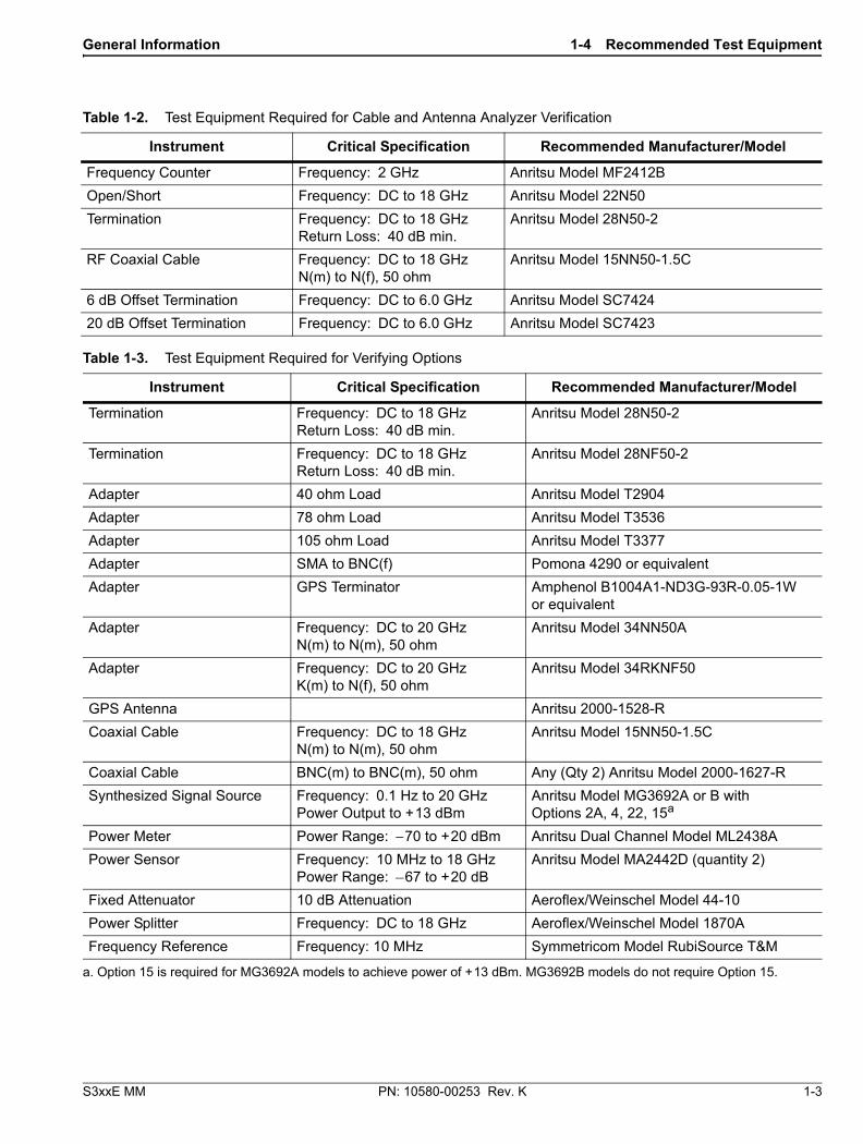
6. Record the Sensor B reading to the –2 dBm column of Table A-7, “Spectrum Analyzer Absolute Amplitude Accuracy Across Frequency Setup Table”.
7. Adjust the MG3692x output level so the Sensor A reading is –30 dBm ± 0.1 dB.
8. Record the Sensor B reading to the –30 dBm column of Table A-7.
9. Adjust the MG3692x output level so the Sensor A reading is –50 dBm ± 0.1 dB.
10. Record the Sensor B reading to the –50 dBm column of Table A-7.
11. Repeat Step 3 through Step 10 for all the frequencies listed in Table A-7.
Figure 2-3. Fixed Level with Varying Frequency Setup
Note Before continuing, allow a 30 minute warm up for the internal circuitry to stabilize.
MG3692x Synthesized Signal Generator
10 MHzReference
ML2438A Power Meter
MA2442DSensor A
MA2442DSensor B
1870A Power Splitter
10 dB FixedAttenuator
Adapter
A
B

2-5 Spectrum Analyzer Absolute Amplitude Accuracy Verification Spectrum Analyzer Verification
2-12 PN: 10580-00253 Rev. K S3xxE MM
Setup
Measuring Amplitude Accuracy Across Frequency
1. Connect the equipment as shown in Figure 2-4.
2. Set the S332E or S362E to Spectrum Analyzer mode and then preset the unit.
3. Press the Shift key, the Sweep (3) key, then the Sweep Mode soft key, and press the Performance soft key.
4. Press the BW soft key. Then set the RBW to 1 kHz and the VBW to 10 Hz.
5. Press the Span soft key, set span to 10 kHz.
6. Press the Freq soft key and set the Center Frequency to 10.1 MHz.
7. Press the Amplitude soft key and set the Reference Level to –40 dBm and turn the Pre-Amp On.
8. Set the Attenuation Level to 15 dB.
Figure 2-4. Absolute Amplitude Accuracy Across Frequency Verification Test Setup
Note To maintain test setup integrity, do not disconnect sensor B, the power splitter or the fixed attenuator.
S3xxE Site Master
Power Charge
+/-.0
3
Sweep
2
Calibrate
1
Preset
6
Limit
5
Trace
4
Measure
9
Mode
8
System
7
File
ShiftBack
Enter
ESC
SiteMasterS332E
MG3692x Synthesized Signal Generator
10 MHzReference
ML2438A Power Meter
MA2442DSensor B
1870A Power Splitter
Adapter
N(m) to N(m) Adaptor
10 dB Attenuator

Spectrum Analyzer Verification 2-5 Spectrum Analyzer Absolute Amplitude Accuracy Verification
S3xxE MM PN: 10580-00253 Rev. K 2-13
9. Set the power meter to display Channel B. Press the Sensor key, the Cal Factor soft key, and then the Freq soft key. Use the keypad to enter the value matching the frequency of MG3692x as the input signal frequency, which sets the power meter to the proper power sensor cal factor. Press the System key to display the power reading.
10. Set the MG3692x frequency to 10.1 MHz CW.
11. Adjust the MG3692x output power so the power meter displays a reading that matches the Sensor B reading for –50 dBm in Table A-7.
12. On the S3xxE, press the Marker key and press the Peak Search soft key.
13. Record the Marker 1 amplitude reading in Table A-8, “Spectrum Analyzer Absolute Amplitude Accuracy Across Frequency”.
14. Verify that the Marker 1 amplitude reading is within the specification.
15. Repeat Step 6 through Step 14 for other frequencies, input power, reference level, attenuation and pre-amp settings in Table A-8.

2-6 Residual Spurious Response Verification Spectrum Analyzer Verification
2-14 PN: 10580-00253 Rev. K S3xxE MM
2-6 Residual Spurious Response VerificationThe following two tests are used to verify the residual spurious response of the Spectrum Analyzer of the S332E and S362E Site Master and is performed using the positive peak detection mode. The two parts to this test are the “Residual Spurious Response Test with Preamp Off” immediately below and “Residual Spurious Response Test with Preamp On” on page 2-15.
Residual Spurious Response Test with Preamp Off
Equipment Required
• Anritsu 28N50-2 50 ohm Termination
Procedure
1. Connect the 50 ohm Termination to the S332E or S362E Spectrum Analyzer RF In connector.
2. Press the On/Off key to turn on the S332E or S362E Site Master.
3. On the S332E or S362E:
a. Press the Shift key and then the Mode (9) key.
b. Rotate the knob to highlight Spectrum Analyzer and then press the Enter key to switch to Spectrum Analyzer mode.
4. Press the Shift key, the Preset (1) key, and then the Preset soft key to reset the instrument to the default starting conditions.
5. Press the Shift key, the Sweep (3) key, then the Sweep Mode soft key, and press the Performance soft key.
6. Press the Amplitude soft key, then press the Reference Level soft key.
7. Use the keypad to enter –40 and press the dBm soft key.
8. Press the Atten Lvl soft key and enter 0, then press the dB soft key.
9. Make sure that the Pre Amp On/Off soft key is in the Off position.
• If the preamp is on, press the Pre Amp On/Off soft key to turn it off.
10. Press the Amplitude soft key, then press the Detection soft key and then the Peak soft key.
11. Press the Freq soft key and press the Start Freq soft key.
12. Use the keypad to enter 10 and press the MHz soft key.
13. Press the Stop Freq soft key, enter 50 and press the MHz soft key.
14. Press the BW soft key and press the RBW soft key.
15. Use the keypad to enter 1 and press the kHz soft key.
16. Press the VBW soft key, use the keypad to enter 300 and then press the Hz soft key.
17. Wait until one sweep is completed.
18. Press the Marker soft key and press the Peak Search soft key.
19. Verify that the Marker 1 amplitude reading is less than –90 dBm.
20. Record the “Marker 1 amplitude” reading to Table A-9, “Spectrum Analyzer Residual Spurious with Preamp Off”.
21. Repeat Step 11 through Step 20 for the other frequency band settings in Table A-9 as applicable to the unit under test.
Note
If a spur larger than –90 dBm appears, wait another full sweep and observe whether the spur reappears at the same point on the second sweep.
If the spur does not appear at the same point on the second sweep, then the spur on the first sweep was not real.

Spectrum Analyzer Verification 2-6 Residual Spurious Response Verification
S3xxE MM PN: 10580-00253 Rev. K 2-15
Residual Spurious Response Test with Preamp On
Equipment Required
• Anritsu 28N50-2 50 ohm Termination
Procedure
1. Connect the 50 ohm Termination to the S332E or S362E Spectrum Analyzer RF In connector.
2. Press the On/Off key to turn on the S332E or S362E Site Master.
3. On the S332E or S362E, press the Shift key and then the Mode (9) key. Rotate the knob to highlight Spectrum Analyzer and then press the Enter key to switch to Spectrum Analyzer mode.
4. Press the Shift key, the Preset (1) key, and then the Preset soft key to reset the instrument to the default starting conditions.
5. Press the Shift key, the Sweep (3) key, then the Sweep Mode soft key, and press the Performance soft key.
6. Press the Amplitude soft key, then press the Reference Level soft key.
7. Use the keypad to enter –50 and press the dBm soft key.
8. Press the Atten Lvl soft key and enter 0, then press the dB soft key.
9. Ensure that the Pre Amp On/Off soft key is in the On position. If the preamp is off, press the Pre Amp On/Off soft key to turn it On.
10. Press the Amplitude soft key, then press the Detection soft key and then the Peak soft key.
11. Press the BW soft key and press the RBW soft key.
12. Use the keypad to enter 10 and press the kHz soft key.
13. Press the VBW soft key and use the keypad to enter 1, then press the kHz soft key.
14. Press the Freq soft key and press the Start Freq soft key.
15. Use the keypad to enter 10 and press the MHz soft key.
16. Press the Stop Freq soft key, enter 1 and press the GHz soft key.
17. Wait until one sweep is completed.
18. Press the Marker soft key and press the Peak Search soft key.
19. Record the “Marker 1 amplitude” reading in the test records and verify that it is less than –90 dBm. Use Table A-10, “Spectrum Analyzer Residual Spurious with Preamp On”.
20. Repeat Step 14 through Step 19 for the other Start and Stop frequencies as applicable for the unit under test and record in Table A-10.
Note Before continuing, allow a 30 minute warm up period for the internal circuitry to stabilize.
Note
If a spur larger than –90 dBm appears, wait another full sweep and observe whether the spur reappears at the same point on the second sweep.
If the spur does not appear at the same point on the second sweep, then the spur on the first sweep was not real.

2-7 Displayed Average Noise Level (DANL) Spectrum Analyzer Verification
2-16 PN: 10580-00253 Rev. K S3xxE MM
2-7 Displayed Average Noise Level (DANL)The following test is used to verify the Displayed Average Noise Level (DANL) of the spectrum analyzer systems in the S332E and S362E Site Master. This test is performed using the RMS detection mode.
Equipment Required
• Anritsu 28N50-2 50 ohm Termination
Procedure
1. Connect the 50 ohm Termination to the S332E or S362E Spectrum Analyzer RF In connector.
2. Press the On/Off key to turn on the S332E or S362E Site Master.
3. On the S332E or S362E, press the Shift key and then the Mode (9) key. Rotate the knob to highlight Spectrum Analyzer and then press the Enter key to switch to Spectrum Analyzer mode.
4. Press the Shift key, the Preset (1) key, and then the Preset soft key to reset the instrument to the default starting conditions.
5. Press the Shift key, the Sweep (3) key, then the Sweep Mode soft key, and press the Performance soft key.
6. Press the Amplitude soft key, then press the Reference Level soft key.
7. Use the keypad to enter –20 and press the dBm soft key.
8. Press the Atten Lvl soft key and enter 0, then press the dB soft key.
9. Make sure that the Preamp is Off.
10. Press the Amplitude soft key, then press the Detection soft key and then the RMS/AVG soft key.
11. Press the BW soft key and press the RBW soft key.
12. Use the keypad to enter 100 and press the kHz soft key.
13. Press the VBW soft key.
14. Use the keypad to enter 1 and press the kHz soft key.
15. Press the Freq soft key and press the Start Freq soft key.
16. Use the keypad to enter 10 and press the MHz soft key.
17. Press the Stop Freq soft key, enter 2.4 and press the GHz soft key.
18. Wait until one sweep is completed.
19. Press the Marker soft key and then press Peak Search soft key.
20. Record the Marker reading to the test records. Use the Measured Value @ 100 kHz RBW column of Table A-11, “Spectrum Analyzer DANL with Pre Amp Off”.
21. Repeat Step 15 through Step 20 for the other frequency settings in Table A-11 that are applicable for the unit under test. Change the VBW setting as indicated in the VBW column of Table A-11.
22. For each measured 100 kHz RBW value in the test record, convert it to 10 Hz RBW value by subtracting 40 dB.
–100 dBm – 40 dB = –140 dBm
Note Before continuing, allow a 30 minute warm up period for the internal circuitry to stabilize.
NoteThe noise floor consists of totally random signals where a spur is a fixed spike of varying amplitude that is always visible.

Spectrum Analyzer Verification 2-7 Displayed Average Noise Level (DANL)
S3xxE MM PN: 10580-00253 Rev. K 2-17
For example, if the marker shows a value of –100 dBm at 100 kHz RBW, the calculated value at 10 Hz RBW is –140 dBm.
23. Enter the calculated values in the test records. Use the Calculated for 10 Hz RBW column of Table A-11.
24. Verify that the calculated value is less than or equal to the value in the Specification column of Table A-11.
25. Press the Amplitude soft key, then press the Reference Level soft key.
26. Use the keypad to enter –50 and press the dBm soft key.
27. Press the Preamp On/Off soft key to turn the preamp On.
28. Repeat Step 11 through Step 24.
29. Record the Marker reading and calculated value in the test record using Table A-12, “Spectrum Analyzer DANL with Pre Amp On”.

2-8 Third Order Intercept (TOI) Verification Spectrum Analyzer Verification
2-18 PN: 10580-00253 Rev. K S3xxE MM
2-8 Third Order Intercept (TOI) VerificationThe following test verifies the Third Order Intercept point (also known as TOI or IP3) of the Spectrum Analyzer in the S332E and S362.
Equipment Required
• Anritsu MG3692x Synthesizer (Qty 2)
• Anritsu ML2438A Power Meter
• Anritsu MA2442D Power Sensor
• Fixed Attenuator, Aeroflex/Weinschel Model 44-2 (Qty 2)
• Fixed Attenuator, Aeroflex/Weinschel Model 44-6 (Qty 2)
• Fixed Attenuator, Aeroflex/Weinschel Model 44-20 (Qty 2)
• Power Splitter, Aeroflex/Weinschel Model 1870A
• Adapter, Anritsu Model 34NN50A
• Frequency Reference Symmetricom Rubisource T&M
Procedure for 800 MHz TOI
1. Connect the 10 MHz Reference from the frequency reference to the 10 MHz Reference Inputs of the two MG3692x synthesizers and the S3x2E.
2. Zero/Cal the MA2442D Power Sensor, and set the calibration factor of the sensor to 800 MHz.
3. Connect the MA2442D Power Sensor to the input of the 1870A splitter.
4. Connect the 28 dB of Attenuation to each output side of the 1870A splitter.
5. Connect one MG3692x to one 28 dB attenuator and connect the other MG3692x to the other 28 dB attenuator. (The normal RF output connections will become input connections, and the normal input connection will become the RF output connection.
6. Set one MG3692x to 799.951 MHz and set the other to 800.051 MHz.
7. Turn the RF Output of one MG3692x Off and turn On the other RF Output. Set the level of the MG3692x that is On so that the MA2442D sensor reads –20 dBm.
8. Turn Off the MG3692x that is On, and turn On the one that is Off. Set the level so the MA2442D reads –20 dBm.
9. Disconnect the MA2442D from the splitter, and connect the splitter to the S3x2E RF In port using the 34NN50A adapter.
10. Turn On the RF Output of the Synthesizer that is off, so that both MG3692x Synthesizers are On.
11. Press the On/Off key to turn On the S3x2E Site Master.
12. Put S3x2E into SPA Mode and Preset the instrument.
13. Using the Frequency menu, set the Center Frequency to 799.851 MHz and the Span to 100 Hz.
14. Using the BW menu, set the RBW to 10 Hz and VBW to 1 Hz.
15. Using the Amplitude menu, set the Reference Level to –15 dBm, ensure that the Pre-Amp is Off, set the Attenuation Level to 10 dB, then choose the Detection sub-menu and press RMS/Avg.
16. Using the Marker menu, press Peak Search and write down the level value.
17. Using the Frequency menu, set the Center Frequency to 800.151 MHz.
18. Using the Marker menu, press Peak Search and write down the level value.
Caution Before continuing, allow a 30 minute warm up period for the internal circuitry to stabilize.

Spectrum Analyzer Verification 2-8 Third Order Intercept (TOI) Verification
S3xxE MM PN: 10580-00253 Rev. K 2-19
19. Choose the larger of the two values from Step 16 and Step 18, and put this value into the following equation as the “max” variable.
TOI = –20 + [(–20 – max) / 2] dBm
20. Record the maximum value and the calculated TOI value in the test record using Table A-13, “Third Order Intercept (TOI) Verification” on page A-11.
Procedure for 2400 MHz TOI
1. Connect the 10 MHz Reference from the frequency reference to the 10 MHz Reference Inputs of the two MG3692x synthesizers and the S3x2E.
2. Zero/Cal the MA2442D Power Sensor, and set the calibration factor of the sensor to 2400 MHz.
3. Connect the MA2442D Power Sensor to the input of the 1870A splitter.
4. Connect the 28 dB of Attenuation to each output side of the 1870A splitter.
5. Connect one MG3692x to one 28 dB attenuator and connect the other MG3692x to the other 28 dB attenuator. (The normal RF output connections will become input connections, and the normal input connection will become the RF output connection.
6. Set one MG3692x to 2399.951 MHz, and set the other to 2400.051 MHz.
7. Turn Off the RF Output of one MG3692x, and turn On the other RF Output. Set the level of the MG3692x that is On so that the MA2442D sensor reads –20 dBm.
8. Turn Off the MG3692x that is on, and turn On the one that is off, and set the level so that the MA2442D reads –20 dBm.
9. Disconnect the MA2442D from the splitter, and connect the splitter to the S3x2E’s RF In port using the 34NN50A adapter.
10. Turn On the RF Output of the Synthesizer that is off, so that both MG3692x Synthesizers are On.
11. Press the On/Off key to turn on the S3x2E Site Master.
12. Put S3x2E into SPA Mode and Preset the instrument.
13. Using the Frequency menu, set the Center Frequency to 2399.851 MHz and the Span to 100 Hz.
14. Using the BW menu, set the RBW to 10 Hz and VBW to 1 Hz.
15. Using the Amplitude menu, set the Reference Level to –15 dBm, ensure that the Pre-Amp is Off, set Attenuation Level to 10 dB, and then choose the Detection sub-menu and press RMS/Avg.
16. Using the Marker menu, press Peak Search and write down the level value.
17. Using the Frequency menu, set the Center Frequency to 2400.151 MHz.
18. Using the Marker menu, press Peak Search, and write down the level value.
19. Choose the larger of the two values from Step 16 and Step 18 and put this value into the following equation as the “max” variable.
TOI = –20 + [(–20 – max) / 2] dBm
20. Record the maximum value and calculated TOI value in the test record using Table A-13.
Caution Before continuing, allow a 30 minute warm up period for the internal circuitry to stabilize.

2-8 Third Order Intercept (TOI) Verification Spectrum Analyzer Verification
2-20 PN: 10580-00253 Rev. K S3xxE MM

S3xxE MM PN: 10580-00253 Rev. K 3-1
Chapter 3 — Cable and Antenna Analyzer Verification
3-1 Frequency Accuracy VerificationThe following test is used to verify the CW frequency accuracy of the RF source on the S3xxE in Cable and Antenna Analyzer mode.
Equipment Required
• Frequency Counter Frequency: 2 GHz Anritsu Model MF2412B
• RF Coaxial Cable Freq: DC to 18 GHz, N(m) to N(m), 50 ohm, Anritsu Model 15NN50-1.5C
Procedure
1. Verify that the S3xxE is in Cable and Antenna Analyzer mode and preset the unit.
2. Verify that no external 10 MHz reference is connected to the S3xxE.
3. Press Shift then the Sweep key.
4. Verify that the RF Immunity is set to High.
5. Press the Freq/Dist key and set both the Start Freq and Stop Freq to 2 GHz.
6. Connect the RF cable from the S3xxE VNA Reflection RF Out to the Frequency Counter.
7. Turn on the Frequency Counter and press the Preset key.
8. Record the frequency data in Table A-14, “VNA Frequency Accuracy.

3-2 Return Loss Accuracy Verification Cable and Antenna Analyzer Verification
3-2 PN: 10580-00253 Rev. K S3xxE MM
3-2 Return Loss Accuracy VerificationThe following test is used to verify the accuracy of return loss measurements on the S3xxE in Cable and Antenna Analyzer mode.
Equipment Required
• Open/Short Frequency: DC to 18 GHz Anritsu Model 22N50
• Termination Frequency: DC to 18 GHz, Return Loss: 40 dB min. Anritsu Model 28N50-2
• 6 dB Offset Termination Frequency: DC to 6.0 GHz Anritsu Model SC7424
• 20 dB Offset Termination Frequency: DC to 6.0 GHz Anritsu Model SC7423
Procedure
1. Verify that the S3xxE is in Cable and Antenna Analyzer mode and preset the unit.
2. Press the Measurement key, then press the Return Loss soft key.
3. Press the Shift key, then press the Calibrate (2) key.
4. Press the Start Cal soft key. Follow the instructions on the screen to perform a calibration.
5. After the calibration is complete, install the 20 dB offset termination.
6. Press the Amplitude key, set Top to 17 dB, and Bottom to 23 dB.
7. Verify that the trace is between 18.3 dB and 21.7 dB.
8. Press the Marker key and press the Marker to Peak soft key. Record the marker value, then press the Marker to Valley soft key and record the marker value. Record the worst case of the two values in Table A-15, “VNA Return Loss Accuracy Verification.
9. Remove the 20 dB offset and install the 6 dB offset.
10. Press the Amplitude key, set Top to 4.0 dB, and set Bottom to 8.0 dB.
11. Verify that the trace is between 4.8 dB and 7.2 dB.
12. Press the Marker key and press the Marker to Peak soft key. Record the marker value, then press the Marker to Valley soft key and record the marker value. Record the worst case of the two values in Table A-15.

S3xxE MM PN: 10580-00253 Rev. K 4-1
Chapter 4 — Option Verification
4-1 IntroductionThis chapter describes the verification process for options available on the S3xxE Site Master.
4-2 Option 10, Bias Tee VerificationThis test verifies that the optional Bias Tee in the Cable and Antenna Analyzer of the Model S3xxE Site Master is functional. These tests include:
• “Low Current Test Verification”
• “High Current Test Verification” on page 4-2
• “Fault Verification” on page 4-3
Low Current Test Verification
The tests in this section verify the Bias Tee, Option 10, low current operation of the S3xxE in Cable and Antenna Analyzer mode.
Equipment Required
• Anritsu 40-187-R External Power Supply
• Anritsu T3377 105 ohm Load
Procedure
1. Connect the external power supply to the S3xxE Site Master.
2. Press the On/Off key to turn on the S3xxE.
3. Set the S3xxE to Cable and Antenna Analyzer mode and preset the unit.
4. Press the Shift key, and then the System (8) key, press the Applications Options soft key.
Low Current Test
1. Press the Bias Tee Voltage soft key and change voltage from 15 V to 12 V, and then confirm that the Current soft key is set to Low.
2. Connect the Anritsu T3377 105 ohm load to the RF In test port.
3. Press the Bias Tee On/Off soft key to turn the Bias Tee On.
4. Record the Voltage and Current readings displayed on the left side of the screen in the 105 ohm Load Low Current section of Table A-16, “Option 10, Bias Tee”. Verify the voltage and current readings are within the specifications.
5. Press the Bias Tee On/Off soft key to turn the Bias Tee Off.
6. Repeat Step 3 through Step 5, entering each of the voltage settings listed in the 105 ohm Load Low Current section of Table A-16.

4-2 Option 10, Bias Tee Verification Option Verification
4-2 PN: 10580-00253 Rev. K S3xxE MM
High Current Test Verification
The tests in this section verify the Bias Tee, Option 10, high current operation of the S3xxE in Cable and Antenna Analyzer mode.
Equipment Required
• Anritsu 40-187-R External Power Supply
• Anritsu T2904 40 ohm Load
• Anritsu T3536 78 ohm Load
Procedure
1. Connect the external power supply to the S3xxE Site Master.
2. Press the On/Off key to turn on the S3xxE.
3. Set the S3xxE to Cable and Antenna Analyzer mode and preset the unit.
4. Press the Shift key, and then the System (8) key, press the Applications Options soft key.
High Current Test
1. Press the Bias Tee Voltage soft key and confirm the voltage is set to 15 V. Confirm the soft key is set to High.
2. Connect the Anritsu T2904 40 ohm load to the RF In test port.
3. Press the Bias Tee On/Off soft key to turn the Bias Tee On.
4. Record the Voltage and Current readings displayed on the left side of the screen in the 40 ohm Load High Current section of Table A-16. Verify the voltage and current readings are within the specifications.
5. Press the Bias Tee On/Off soft key to turn the Bias Tee Off. Disconnect the Anritsu T2904 40 ohm load and connect the Anritsu T3536 78 ohm load to the RF In port.
6. Press the Bias Tee Voltage soft key and enter 32 V.
7. Press the Bias Tee On/Off soft key to turn the Bias Tee On.
8. Record the Voltage and Current readings displayed on the left side of the screen in the 78 ohm Load High Current section of Table A-16. Verify the voltage and current readings are within the specifications.
9. Press the Bias Tee On/Off soft key to turn the Bias Tee Off.

Option Verification 4-2 Option 10, Bias Tee Verification
S3xxE MM PN: 10580-00253 Rev. K 4-3
Fault Verification
The tests in this section verify the Bias Tee, Option 10, fault condition of the S3xxE in Cable and Antenna Analyzer mode.
Equipment Required
• Anritsu 40-187-R External Power Supply
• Anritsu T2904 40 ohm Load
Procedure
1. Connect the external power supply to the S3xxE Site Master.
2. Press the On/Off key to turn on the S3xxE.
3. Set the S3xxE to Cable and Antenna Analyzer mode and preset the unit.
4. Press the Shift key, and then the System (8) key, press the Applications Options soft key.
Fault Test
5. Press the Bias Tee soft key and confirm that the Current soft key is set to Low.
6. Press the Bias Tee Voltage soft key and enter 32 V.
7. Connect the Anritsu T2904 40 ohm load to the RF In port.
8. Press the Bias Tee On/Off soft key to turn the Bias Tee On.
9. Verify that the instrument makes a clicking sound and that the Bias Tee current reading displayed on the left side of the screen is 0 mA.
10. Press the Bias Tee On/Off soft key to turn the Bias Tee Off.

4-3 Option 21, Transmission Measurement, System Dynamic Range Option Verification
4-4 PN: 10580-00253 Rev. K S3xxE MM
4-3 Option 21, Transmission Measurement, System Dynamic RangeThe following test is used to verify the system dynamic range for Site Masters with Option 21, 2-Port Transmission Measurement, installed.
Equipment Required
• Termination Frequency: DC to 18 GHz Return Loss: 40 dB min. Anritsu Model 28N50-2
• Termination Frequency: DC to 18 GHz Return Loss: 40 dB min. Anritsu Model 28NF50-2
• RF Coaxial Cable Freq: DC to 18 GHz N(m) to N(m), 50 ohm Anritsu Model 15NN50-1.5C
Procedure
1. Verify that the S3xxE is in Transmission Measurement mode and preset the unit.
2. Press the Shift key, then press the Sweep (3) key.
3. Verify that High Dynamic Range is set to On
4. Verify that the Output Power is set to High.
5. Press the Measure soft key.
6. Press the Start Cal soft key and follow the on screen instructions to perform calibration.
7. After the calibration is complete, disconnect one end of the cable and connect loads so both the RF Out (Reflection In) and RF In ports are terminated.
8. Press the Sweep soft key and then press Averaging. Confirm that Averaging Off is pressed, indicated by the red dot in the top right hand corner.
9. Press the Amplitude soft key and set the Top to –50 dB and Scale to 10 dB/div.
10. Press Shift, Limit (6), and set the Limit to On.
11. Press the Multi-Segment Edit soft key and verify that the Point Frequency is set to 2 MHz.
12. Press Amplitude vertical soft key and set the limit to –80 dB.
13. Press Add Point, press Point Frequency, and enter 4.0 GHz.
14. Press Amplitude vertical soft key and enter –80 dB.
Perform Step 15 through Step 18 for S36xE units only,
15. Press Add Point, press Point Frequency, and enter 4.01 GHz.
16. Press Amplitude vertical soft key and enter –70 dB.
17. Press Add Point and press Point Frequency, and enter 6.00 GHz.
18. Press Amplitude vertical soft key and enter –70 dB.
19. Verify the display of the system dynamic range is below the limit lines (the data will be unstable, but should remain below the limit lines.)
20. Use a marker to find the maximum peak of each frequency band and enter the value in dB in Table A-17, “Option 21, VNA System Dynamic Range Verification”.

Option Verification 4-4 Option 29, Power Meter Level Accuracy
S3xxE MM PN: 10580-00253 Rev. K 4-5
4-4 Option 29, Power Meter Level AccuracyThe following test verifies the level accuracy of the S332E or S362E Power Meter for Site Masters with Option 29 installed.
Equipment Required
• Anritsu MG3692X Synthesized Signal Source
• Anritsu ML2438A Dual Channel Power Meter
• Anritsu MA2442D High Accuracy Power Sensors (2)
• Anritsu 34NN50A 50 ohm Adapter
• Anritsu 34RKNF50 50 ohm Adapter
• Anritsu 15NN50-1.5C RF Coaxial Cable
• Aeroflex/Weinschel 1870A Power Splitter
• Aeroflex/Weinschel 44-10 10 dB Fixed Attenuator
Setup
Figure 4-1. Power Meter Measurement Accuracy
MG3692x Synthesized Signal Generator
10 MHzReference
ML2438A Power Meter
MA2442DSensor A
MA2442DSensor B
1870A Power Splitter
10 dB FixedAttenuator
Adapter
A
B

4-4 Option 29, Power Meter Level Accuracy Option Verification
4-6 PN: 10580-00253 Rev. K S3xxE MM
Procedure Component Characterization:
1. Connect both MA2442D power sensors to the power meter and calibrate the sensors.
2. Connect the model 1870A power splitter to the MG3692A/B output and sensor B to one of the power splitter outputs as shown on the previous page. (Figure 4-1 on page 4-5).
3. Install the 10 dB Fixed Attenuator to the other power splitter output and then connect sensor A to the end of the Attenuator.
4. Set the power meter to display both Channels A and B. Press the Sensor key, the Cal Factor soft key, and then the Freq soft key. Use the keypad to enter the value matching the frequency of MG3692A/B as the input signal frequency, which sets the power meter to the proper power sensor cal factor. Repeat for Channel B. Press the System key to display the power reading.
5. Adjust the power level of the MG3692A/B to get a reading on sensor A that matches the power level (within ± 0.1 dB) in the first column of Table A-18, “Option 29, Characterization Chart for Power Meter Verification” on page A-14.
6. Record the sensor B reading in the Required Sensor B Reading column of Table A-18.
7. Repeat Step 5 and Step 6 for the other power level in the first column of Table A-18, recording the Sensor B reading in the second column.
8. Repeat the above steps for the next input frequency.
Power Meter Measurement Accuracy Procedure
1. Connect the equipment as shown in Figure 4-2.
Figure 4-2. Power Meter Measurement Accuracy
S3xxE Site Master
Power Charge
+/-.0
3
Sweep
2
Calibrate
1
Preset
6
Limit
5
Trace
4
Measure
9
Mode
8
System
7
File
ShiftBack
Enter
ESC
SiteMasterS332E
MG3692x Synthesized Signal Generator
10 MHzReference
ML2438A Power Meter
MA2442DSensor B
1870A Power Splitter
Adapter
N(m) to N(m) Adaptor
10 dB Attenuator

Option Verification 4-5 Option 31, GPS Verification
S3xxE MM PN: 10580-00253 Rev. K 4-7
2. Verify that the S3xxE is in the Power Meter mode and preset the unit.
3. Set the S3xxE span to 3 MHz.
4. Set the S3xxE center frequency to 50 MHz.
5. Adjust the MG3692A/B power so that the power meter sensor B matches the sensor B value shown in the Table A-18.
6. Record the reading on the S3xxE display in Table A-19, “Option 29, Internal Power Meter Accuracy Verification” on page A-14.
7. Repeat Step 4 to Step 6 for the next test power level in Table A-19.
8. Repeat Step 4 to Step 6 for the next test frequency in Table A-19.
4-5 Option 31, GPS VerificationThis test verifies the GPS option on the S3xxE Site Master is functional.
Frequency Accuracy Verification (Only for models S332E and S362E)
The test in this section verifies the Spectrum Analyzer Frequency Accuracy with GPS, Option 31, of the S332E and S362E in Spectrum Analyzer mode.
Equipment Required
• Anritsu MG3692X Synthesized Signal Source
• 10 MHz Reference Standard
• Anritsu 34RKNF50 50 ohm Adapter
• Anritsu 15NN50-1.5C RF Coaxial Cable
• Anritsu 2000-1528-R GPS Antenna
Procedure
1. Connect the GPS antenna to the GPS Antenna connector on the S332E or S362E. On the S332E or S362E, change the mode to Spectrum Analyzer and preset the unit.
2. Press the Shift key and then the System key.
3. Press the GPS soft key, then press the GPS On/Off soft key to turn the GPS On.
4. When the GPS fix is acquired, the GPS indicator at the top of the LCD display will turn green.
5. The latitude and the longitude will also be displayed next to the GPS indicator.
6. Wait for about three minutes after the Reference Source indicator in the lower left hand corner of the LCD display has changed to GPS High Accuracy.
Note
If a fixed GPS antenna is not available, the Anritsu 2000-1528-R GPS antenna can be used for this test.
Confirm that the Anritsu 2000-1528-R GPS antenna is in direct line-of-sight relationship to the satellites by placing the antenna outside without any obstructions.
Note
If GPS fix is acquired using the Anritsu 2000-1528-R GPS antenna placed outside, bringing the instrument inside will lose satellite tracking. A red cross will appear on the green GPS indicator and the Reference Source indicator will change to “Int Hi Accy”. The following test will verify frequency accuracy to a lesser specification.

4-5 Option 31, GPS Verification Option Verification
4-8 PN: 10580-00253 Rev. K S3xxE MM
7. Connect the external 10 MHz Reference to the Anritsu MG3692x Synthesized Signal Generator.
8. Connect the output of the synthesized Signal Generator to the Spectrum Analyzer RF In of the S332E or S362E.
9. Set the MG3692x output to 4 GHz CW, with an RF output level of –30 dBm.
10. On the S332E or S362E, press the Amplitude key, and set the reference level to –10 dBm.
11. Press the Freq soft key and set the center frequency to 4.0 GHz.
12. Press the Span soft key and set the span to 10 kHz.
13. Press the BW soft key and set RBW to 100 Hz.
14. Press the VBW soft key and set to 30 Hz.
15. Press the Marker key, and press the Peak Search soft key.
16. Note the Reference Source value and use the appropriate row to record the data in the following steps.
17. Record the marker frequency in the Measured Value column of Table A-20, “Option 31, GPS Receiver Frequency Accuracy Verification”.
18. Subtract the marker value from 4 GHz and record the result in the Error column of Table A-20. Verify that it is within specification.
19. If the value of Reference Source indicates GPS High Accuracy, then remove the GPS antenna and wait until the Reference Source indicates “Int Hi Accy” and repeat Step 16 through Step 18.
GPS Antenna Bias Tee Verification
The tests in this section verify the GPS Antenna Bias Tee Voltages of Option 31 on the S3xxE Site Master.
Equipment Required
• Adapter SMA to BNC(f), Pomona 4290 or equivalent
• Adapter GPS Terminator, Amphenol B1004A1-ND3G-93R-0.05-1W or equivalent
Procedure
1. Connect the external power supply to the S3xxE Site Master.
2. Press the On/Off key to turn on the S3xxE.
3. Set the S3xxE to Spectrum Analyzer mode and preset the unit.
4. Press the Shift key, and then the System (3) key.
3.3 V Test
5. Connect the 4290 Adapter to the GPS Antenna SMA connector.
6. Connect the GPS Terminator to the 4290 Adapter.
7. Confirm the 3.3 V setting on the GPS Voltage soft key is selected (underlined)
8. Turn GPS On by toggling the GPS soft key so the On text is underlined.
9. Press the GPS Info soft key. Record the GPS Antenna Current reading in the Measured Value column of Table A-21, “Option 31, GPS Receiver Bias Tee Verification”. Verify that it is within specification.
5 V Test
10. Press the Escape key to dismiss the GPS Info dialog.
11. Press the GPS Voltage soft key and select 5 V.
Note Do not connect the external 10 MHz Reference to the S3xxE Site Master.

Option Verification 4-5 Option 31, GPS Verification
S3xxE MM PN: 10580-00253 Rev. K 4-9
12. Press the GPS Info soft key. Record the GPS Antenna Current reading in the Measured Value column of Table A-21. Verify that it is within specification.

4-5 Option 31, GPS Verification Option Verification
4-10 PN: 10580-00253 Rev. K S3xxE MM

S3xxE MM PN: 10580-00253 Rev. K 5-1
Chapter 5 — Battery Information
5-1 General InformationThe following information relates to the care and handling of the Anritsu battery pack and Lithium-Ion batteries.
• The battery supplied with the Site Master may need charging before use. Before using the Site Master, the internal battery may be charged either in the unit using the AC-DC Adapter (40-187-R) or the 12-Volt DC adapter (806-141-R), or separately in the optional Dual Battery Charger (2000-1374).
• Use only Anritsu approved battery packs.
• Recharge the battery only in the Site Master or in an Anritsu approved charger.
• When the Site Master or the charger is not in use, disconnect it from the power source.
• Do not charge batteries for longer than 24 hours; overcharging may shorten battery life.
• If left unused a fully charged battery will discharge itself over time.
• Temperature extremes affect the ability of the battery to charge: allow the battery to cool down or warm up as necessary before use or charging.
• Discharge the battery from time to time to improve battery performance and battery life.
• The battery can be charged and discharged hundreds of times, but it will eventually wear out.
• The battery may need to be replaced when the operating time between charging becomes noticeably shorter than normal.
• Never use a damaged or worn out charger or battery.
• Storing the battery in extreme hot or cold places will reduce the capacity and lifetime of the battery.
• Never short-circuit the battery terminals.
• Do not drop, mutilate or attempt to disassemble the battery.
• Do not dispose of batteries in a fire!
• Batteries must be recycled or disposed of properly. Do not place batteries in household garbage.
• Always use the battery for its intended purpose only.

5-2 Battery Pack Removal and Replacement Battery Information
5-2 PN: 10580-00253 Rev. K S3xxE MM
5-2 Battery Pack Removal and Replacement This section provides instructions for the removal and replacement of the Site Master battery pack.
1. Locate the battery access door illustrated in Figure 5-1.
2. Place a finger in the battery access door notch and push the door latch down towards the bottom of the instrument, as illustrated in Figure 5-2.
3. Remove the battery access door, the top will pop out a bit and then pull it up out of the access enclosure.
NoteMany of the procedures in this section are generic, and apply to many similar instruments. Photos and illustrations used are representative and may show instruments other than the Site Master.
Figure 5-1. Battery Access Door Location and Finger Notch
Figure 5-2. Opening the Battery Access Door
Battery DoorLocation and Finger Notch

Battery Information 5-2 Battery Pack Removal and Replacement
S3xxE MM PN: 10580-00253 Rev. K 5-3
4. With the battery access door completely removed, grasp the battery lanyard and pull the battery straight out of the unit, as illustrated in Figure 5-3.
5. Replacement is the opposite of removal. Note the orientation of the battery contacts, and be sure to insert the battery with the contacts facing the front of the unit, refer to Figure 5-3 and Figure 5-4.
Figure 5-3. Removing the Battery
Figure 5-4. Battery Contacts and Orientation
Battery Lanyard Battery
Contacts
Insert battery with this side facing the front of the unit.

5-2 Battery Pack Removal and Replacement Battery Information
5-4 PN: 10580-00253 Rev. K S3xxE MM

S3xxE MM PN: 10580-00253 Rev. K 6-1
Chapter 6 — Assembly Replacement
6-1 Opening the Site Master Case
This procedure provides instructions for opening the Site Master case. With the case opened, the internal assemblies can be removed and replaced, as detailed in the following sections.
1. Remove the battery door and battery as shown in Section 5-2 “Battery Pack Removal and Replacement ” on page 5-2.
2. Remove the top and bottom bumpers (Figure 6-1) to expose the screw holes on the back of the unit.
3. Place the Site Master face down on a stable work surface that will not scratch the display.
NoteMany of the procedures in this section are generic, and apply to many similar instruments. Photos and illustrations used are representative and may not match your instrument.
Caution
Only qualified personnel should open the case and replace internal assemblies. Assemblies shown in Table 1-4 are typically the only items that may be replaced. Because they are highly fragile, items that must be soldered may not be replaced without specialized training.
Removing RF shields from PC boards or adjustment of screws on or near the shields may detune sensitive RF circuits and will result in degraded instrument performance. All work should be performed in a static-safe work area.
Caution
Electrostatic Discharge (ESD) can damage the highly sensitive circuits in the instrument.
Repair of damage that is found to be caused by electrostatic discharge is not covered under warranty.
The Site Master contains components that can be easily damaged by electrostatic discharge (ESD). An ESD safe work area and proper ESD handling procedures that conform to ANSI/ESD S20.20-1999 or ANSI/ESD S20.20-2007 is mandatory to avoid ESD damage when handling subassemblies or components found in the instrument.
Figure 6-1. Top Bumper and Option 31
Top Bumper
GPS Connnector
for Option 31

6-1 Opening the Site Master Case Assembly Replacement
6-2 PN: 10580-00253 Rev. K S3xxE MM
4. Use a Phillips screwdriver to remove the six screws securing the two halves of the Site Master case together (Figure 6-2).
5. Carefully lift up on the side of the case indicated above and begin to separate the two halves.
6. Lay the Site Master flat and remove the battery connector cable between the two halves (Figure 6-3).
7. Closing the case is the reverse of opening. Ensure all cables are properly seated and none are pinched before closing the case. The torque setting for the 6 case screws is 7.5 lbf·in (0.85 N·m).
Figure 6-2. Remove the Four Screws
Figure 6-3. Site Master Opened 180 Degrees
Carefully lift
this side first
Location of the 6 screws to remove.
RTC Battery
Disconnect battery cable to
separate the case halves.

Assembly Replacement 6-2 PCB Assembly Removal
S3xxE MM PN: 10580-00253 Rev. K 6-3
6-2 PCB Assembly Removal
This procedure provides instructions to remove the Motherboard/VNA and SPA (if installed) from the Site Master case.
1. Open the case as described in Section 6-1 “Opening the Site Master Case”.
2. Disconnect the keypad PCB cable, the fan assembly cable, and the LCD cable.
3. Use a Phillips screwdriver to remove the 8 screws securing the assemblies to the case (Figure 6-4).
4. After the screws are removed the entire assembly (including the top connector panel) can slide out of the case.
5. Installation is the reverse of removal. Take care to properly fit the connector panel into the grooves in the top of the case and confirm none of the cables will be pinched when the back case is replaced. The torque setting for the 8 screws securing the PCB assembly to the front case is 7.5 lbf·in (0.85 N·m).
NoteProcedures in this section are generic, and apply to many similar instruments. Photos and illustrations of assemblies are representative, actual assemblies may vary.
Figure 6-4. Removing the PCB Assembly out of the Case
NoteThe MCX cable attached to SPA connector J61 (100 MHz) is shown passing above the SPA PCB ribbon cable. It must be routed under the ribbon cable, not as shown in Figure 6-4.
Disconnect
Keypad PCB
Cable
Remove
2 screws
on side
Remove
2 screws
on side
Disconnect
Fan Cable
Disconnect
LCD Cable
Remove 4 screws on the Motherboard

6-3 SPA Assembly Replacement Assembly Replacement
6-4 PN: 10580-00253 Rev. K S3xxE MM
6-3 SPA Assembly ReplacementThis procedure provides instructions to remove the SPA assembly.
1. Open the case as described in Section 6-1 “Opening the Site Master Case”.
2. Remove the PCB assembly from the front panel as described in Section 6-2 “PCB Assembly Removal”.
3. Remove the castle nuts from the External Reference connector and the External Trigger connector (Figure 6-5).
4. Disconnect the ribbon cable.
5. Disconnect the 2 MCX cables between the SPA PCB and the DSP PCB.
6. Remove the 6 screws securing the SPA PCB.
7. Slide the SPA PCB out of the top panel.
8. Installation is the reverse of removal. The torque setting for the 6 screws is 7.5 lbf·in (0.85 N·m).
Figure 6-5. Removing the SPA Assembly
NoteThe MCX cable attached to SPA connector J61 (100 MHz) is shown passing above the SPA PCB ribbon cable. It must be routed under the ribbon cable, not as shown in Figure 6-5.
Remove
3 screws
Remove Castle Nuts
Disconnect
Ribbon Cable
Disconnect
MCX Cables
SPA BoardRemove
3 Screws
DSP Board

Assembly Replacement 6-4 SPA and MB/VNA N Connector Replacement
S3xxE MM PN: 10580-00253 Rev. K 6-5
6-4 SPA and MB/VNA N Connector ReplacementThis procedure provides instructions to replace the N connector attached to the SPA (if installed) or MB/VNA assembly.
1. Open the case as described in Section 6-1 “Opening the Site Master Case”.
2. Remove the PCB assembly from the front panel as described in Section 6-2 “PCB Assembly Removal”.
3. Remove the SPA assembly as described in Section 6-3 “SPA Assembly Replacement”.
4. If removing the MB/VNA N connector, remove the top plate from the MB/VNA.
5. Remove the four screws attaching the N connector to the shield (Figure 6-6).
6. Disconnect the N connector from the SPA or MB/VNA by gently pulling the N connector away from the SPA or MB/VNA (Figure 6-7).
7. Installation is the reverse of removal. The torque setting for the screws is 7.5 lbf·in (0.85 N·m).
Figure 6-6. Remove 4 Screws
Figure 6-7. Remove N Connector from SPA or MB/VNA
Remove 4 Screws

6-5 GPS (Opt. 31) Replacement Assembly Replacement
6-6 PN: 10580-00253 Rev. K S3xxE MM
6-5 GPS (Opt. 31) ReplacementThis procedure provides instructions to replace the GPS assembly.
1. Open the case as described in Section 6-1 “Opening the Site Master Case”.
2. Remove the PCB assembly from the front panel as described in Section 6-2 “PCB Assembly Removal”.
3. Remove the SPA assembly as described in Section 6-3 “SPA Assembly Replacement”.
4. Use a 5/16 inch wrench to remove the nut and washer from the GPS SMA connector. Push the connector through the top panel.
5. Remove the 2 screws retaining the GPS PCB to the Motherboard.
6. Carefully lift straight up on the GPS PCB to remove. The back of the GPS PCB is directly connected to the Motherboard.
7. Installation is the reverse of removal.
NoteThe SPA to DSP cables and the DSP PCB do not need to be removed when replacing the GPS Module. Remove the screws securing the SPA to the bracket and move the SPA to the side.
Figure 6-8. Removing the GPS PCB from the Motherboard (SPA PCB already removed)
Remove
2 screws
Remove nut and waster
from GPS SMA connector

Assembly Replacement 6-6 Option Assembly Replacement
S3xxE MM PN: 10580-00253 Rev. K 6-7
6-6 Option Assembly ReplacementThis procedure provides instructions to replace the Ethernet (Option 411) or CPRI (Option 751) assembly.
1. Open the case as described in Section 6-1 “Opening the Site Master Case”.
2. Remove the PCB assembly from the front panel as described in Section 6-2 “PCB Assembly Removal”.
3. Remove the SPA PCB (if installed) as described in Section 6-3 “SPA Assembly Replacement”.
4. Remove the screws securing the Option PCB to the Main PCB as shown in Figure 6-9.
5. Installation is the reverse of removal.
6-7 Motherboard/VNA Assembly ReplacementThis procedure provides instructions to replace the Motherboard/VNA assembly.
1. Open the case as described in Section 6-1 “Opening the Site Master Case”.
2. Remove the PCB assembly from the front panel as described in Section 6-2 “PCB Assembly Removal”.
3. Remove the SPA PCB (if installed) as described in Section 6-3 “SPA Assembly Replacement”.
4. Remove the GPS PCB (if installed) as described in Section 6-5 “GPS (Opt. 31) Replacement”
5. Remove the Option PCB (if installed) as described in Section 6-6 “Option Assembly Replacement”.
6. Installation is the reverse of removal.
Figure 6-9. Remove Screws Securing Option PCB to Main PCB
NoteWhen ordering the Main/VNA PCB assembly all options that are installed on the instrument must be stated on the order.

6-8 Fan Assembly Replacement Assembly Replacement
6-8 PN: 10580-00253 Rev. K S3xxE MM
6-8 Fan Assembly Replacement This procedure provides instructions to replace the fan assembly.
1. Open the case as described in Section 6-1 “Opening the Site Master Case”.
2. Remove the PCB assembly from the front panel as described in Section 6-2 “PCB Assembly Removal”.
3. The fan is attached to the LCD housing by either three screws or three rubber mounts. If screws are used, remove the screws to remove the fan and re-use the existing screws to secure the replacement fan. If rubber mounts are used, cut the rubber mounts in order to remove the fan, and new rubber mounts will be included with the replacement fan assembly. Refer to (Figure 6-10).
4. Reverse the above steps to install the replacement fan assembly.
Note The fan connector cable is routed through the LCD housing
Figure 6-10. Front Panel Showing Fan Assembly
Fan Assembly
Fan Connector cables
go though the LCD
Assembly housing

Assembly Replacement 6-9 LCD Assembly Replacement
S3xxE MM PN: 10580-00253 Rev. K 6-9
6-9 LCD Assembly ReplacementThis procedure provides instructions to replace the liquid crystal display (LCD).
1. Open the case as described in Section 6-1 “Opening the Site Master Case”.
2. Remove the PCB assembly as described in Section 6-2 “PCB Assembly Removal”.
3. Remove the 9 screws connecting the LCD assembly to the front half of the case, see Figure 6-11.
Figure 6-11. Removing the LCD Assembly
Remove the 9 screws holding the LCD Assembly to the case.

6-9 LCD Assembly Replacement Assembly Replacement
6-10 PN: 10580-00253 Rev. K S3xxE MM
4. Turn the LCD assembly over and disconnect the front half of the case from the LCD assembly (Figure 6-12).
5. Use a Phillips screwdriver to remove the four screws securing the LCD to the housing, see Figure 6-13.
Figure 6-12. Replacing the LCD Assembly
Figure 6-13. Replacing the LCD
Disconnect Cable
LCD Cable to
Motherboard
Remove 4 screws to replace LCD
LCD Backlight
Cable
LCD Backlight
PCB

Assembly Replacement 6-10 LCD Backlight PCB Removal and Replacement
S3xxE MM PN: 10580-00253 Rev. K 6-11
6. Disconnect the LCD backlight cable from the LCD backlight PCB.
7. Disconnect the LCD cable from the side of the LCD.
8. Carefully remove the LCD.
9. Reverse the above steps to install the replacement LCD.
6-10 LCD Backlight PCB Removal and Replacement This procedure provides instructions to replace the Site Master LCD backlight PCB. (Newer units will not have this PCB.)
1. Open the case as described in Section 6-1 “Opening the Site Master Case”.
2. Remove the PCB assembly from the front panel as described in Section 6-2 “PCB Assembly Removal”.
3. Perform Step 1 through Step 4 of Section 6-9 “LCD Assembly Replacement”.
4. Disconnect the LCD backlight cable from the LCD backlight PCB.
5. Use a Phillips screwdriver to remove the two screws securing the LCD backlight PCB to the LCD bracket (Figure 6-14).
6. Carefully remove the LCD Backlight PCB.
7. Reverse the above steps to install the replacement LCD Backlight PCB.
NotePay attention to the routing of the LCD Backlight Cable. The cable must be positioned so it is not pinched when the unit is reassembled.
Figure 6-14. Replacing the LCD PCB
NotePay attention to the routing of the LCD Backlight Cable. The cable must be positioned so it is not pinched when the unit is reassembled.
Remove 2 screws to replace LCD PCB
LCD Backlight
Cable
Ribbon Cable
Connects to
Keypad PCB

6-11 Keypad and Keypad PCB Replacement Assembly Replacement
6-12 PN: 10580-00253 Rev. K S3xxE MM
6-11 Keypad and Keypad PCB Replacement This procedure provides instructions to replace the rubber keypad and the keypad PCB.
1. Open the case as described in Section 6-1 “Opening the Site Master Case”.
2. Remove the PCB assembly from the front panel as described in Section 6-2 “PCB Assembly Removal”.
3. Perform Step 1 through Step 4 of Section 6-9 “LCD Assembly Replacement”.
4. Remove the 8 screws and the cables attached to the keypad PCB allowing removal of the keypad PCB (Figure 6-15). The rubber keypad is located under the keypad PCB.
5. Reverse the above steps to install the replacement rubber keypad and/or keypad PCB.
6. The keypad PCB stores the touch screen calibration data. If the keypad PCB is replaced, then a touch screen calibration must be performed. If no touch screen calibration data is stored in the new keypad PCB when powering on a unit, it will stay at the boot up screen with the Anritsu logo shown and a message at the bottom of the screen stating:
Failed to load touch screen calibration data. Please reboot the instrument.
If this message is displayed, power off the unit and power the unit on in bootstrap mode by pressing and holding down the Shift - 4 - 0 keys while pressing the power on button. Now the unit will boot up in bootstrap mode and prompt you to perform a touch-screen calibration. After following the on-screen calibration directions, power the unit off and it will boot up correctly on the next power cycle.
7. If the keypad PCB was replaced with a PCB that has touch screen calibration data, the unit will boot up properly, but the touch-screen calibration data may not be accurate. Perform a touch-screen calibration by pressing the Shift key and then the 0 key, and follow the on-screen calibration directions.
Figure 6-15. Front Panel Keypad Bezel
Speaker
Rotary Knob
Encoder
Touch Screen
Connector
Touch Screen
Keypad Switch
Connector
Keypad PCB (Remove 8 Screws)
Backlight PCB
Connector

Assembly Replacement 6-12 Touch Screen Replacement
S3xxE MM PN: 10580-00253 Rev. K 6-13
6-12 Touch Screen Replacement This procedure provides instructions to replace the touch screen.
1. Open the case as described in Section 6-1 “Opening the Site Master Case”.
2. Remove the PCB assembly from the front panel as described in Section 6-2 “PCB Assembly Removal”.
3. Perform Step 1 through Step 4 of Section 6-9 “LCD Assembly Replacement”
4. Remove the touch screen flex circuit cable from the keypad PCB by pulling the tabs on each side of the connector away from the connector and in the direction of the flex circuit. Refer to Figure 6-16.
5. Pull the touch screen cable out of the connector housing.
6. Remove the touch screen from the bezel by pulling it straight up.
7. Reverse the above steps to install the replacement touch screen.
8. Perform a touch screen calibration by pressing the Shift key and then the 0 key, and follow the on-screen calibration directions.
Figure 6-16. Replacing the Touch Screen
Touch Screen
Touch Screen Connector.
Pull down on the Tabs at the
Sides of the Connector
to Remove.

6-12 Touch Screen Replacement Assembly Replacement
6-14 PN: 10580-00253 Rev. K S3xxE MM

S3xxE MM PN: 10580-00253 Rev. K 7-1
Chapter 7 — Troubleshooting
7-1 IntroductionThis chapter describes the primary troubleshooting operations that can be performed by all Anritsu Service Centers. Perform the troubleshooting suggestions in the order they are listed. Operators of the MP1026B should refer to the User Guide for troubleshooting help.
Only qualified Anritsu personnel should replace internal assemblies. Major subassemblies shown in Table 1-4, “List of Replaceable Parts” on page 1-4 are typically the items that may be replaced. Because they are highly fragile, items that must be soldered may not be replaced without special training. Removal of RF shields from PC boards or adjustment of screws on or near the shields will detune sensitive RF circuits and will result in degraded instrument performance.
7-2 Turn-on ProblemsUnit cannot boot-up, no activity occurs when the On/Off key is pressed:
1. Battery may be fully discharged. Confirm the battery is installed into the unit and connect the AC to DC converter (Anritsu part number 40-187-R) to the unit allowing the battery to charge.
2. Battery may be the wrong type. Use only Anritsu approved battery packs. Some non-approved battery packs will fit into the MP1026B, but are electrically incompatible and will not charge correctly.
3. External power supply may have failed or be the wrong type. Replace the external power supply.
4. The On/Off switch is damaged. Replace the keypad PCB or rubber keypad.
5. The Main PCB has failed. Replace the Main PCB/Spectrum Analyzer assembly.
Unit begins the boot process, but does not complete boot-up:
1. Using Master Software Tools, perform the Emergency Repair procedure, then update the system software (via the Tools menu).
2. During the boot-up process, the unit stops with the message:
Failed to load touch screen calibration data. Please reboot the instrument.
a. Power the unit off and boot up in boot strap mode (hold down the Shift - 4 - 0 keys while pressing the power on button).
b. In boot strap mode, the unit prompts you to perform a touch screen calibration. Follow the on-screen directions until the touch screen calibration is complete, and then power cycle the unit.
c. Once the unit boots up, ensure the firmware version is 1.30 or greater. If not, load the latest firmware and perform a touch screen calibration.
3. The Main PCB has failed. Replace the Main PCB/Spectrum Analyzer assembly.
Unit makes normal boot-up sounds, but the display has a problem:
1. If the display is dim, check the brightness setting under the System Menu / System Options.
2. Replace the Backlight Driver PCB.
3. Replace the LCD assembly.
4. The Main PCB has failed. Replace the Main PCB/Spectrum Analyzer assembly.
Boot-up Self Test fails:
1. Perform a Master Reset.
2. Verify the date and time are correct on the unit.
3. The Main PCB has failed. Replace the Main PCB/Spectrum Analyzer assembly

7-3 Other Problems Troubleshooting
7-2 PN: 10580-00253 Rev. K S3xxE MM
7-3 Other ProblemsTouch Screen Problems:
Unit boots correctly, but the touch screen is unresponsive.
1. The touch screen may have lost its calibration data. Press Shift then 0 to enter the touch screen calibration procedure. Follow the on-screen directions.
2. Check the firmware version installed on the unit and ensure it is version 1.30 or greater. If not, install the latest firmware version and redo the touch screen calibration as described in Step 1.
3. Replace the touch screen.
Battery Pack Charging Problems:
Refer to Chapter 5, “Battery Information”.
Lock Error messages:
1. This message normally appears for 2 to 3 seconds when an external 10 MHz Reference is applied.
2. Spectrum Analyzer PCB has failed. Replace the Main/Spectrum Analyzer assembly.
Option 5, Power Monitor Problems:
1. Verify correct operation of RF detector (see User’s Guide for a list of suitable detectors).
2. Replace the Option 5 PCB. No recalibration is required.
Spectrum Analyzer Problems:
1. Inspect the Spectrum Analyzer RF In connector for damage.
2. Refer to the User Guide.
3. Update system software using Master Software Tools (via Tools menu).
4. Spectrum Analyzer PCB has failed. Replace the Main/Spectrum Analyzer assembly.
Cable and Antenna Analyzer Problems:
1. Inspect the VNA RF In and VNA Reflection connectors for damage.
2. Inspect the Open, Short, Load and cable(s) for damage. Verify their operation on a suitable measurement instrument.
3. Refer to the User Guide.
4. Update system software using Master Software Tools (via Tools menu).
5. VNA module has failed. Replace the VNA module. No recalibration is required.
Option 50 Problems:
1. Replace the VNA Module with Option 50 assembly. This assembly has been calibrated at the factory.
Option 51, 52 or 53 Problems:
1. Replace the Option 51, 52, or 53 PCB (see Table 1-4, “List of Replaceable Parts” on page 1-4). No recalibration is required.
Other Issues:
1. Perform a Master Reset.
2. Refer to the User Guide.
3. Update system software using Master Software Tools (via Tools menu).
4. Replace the Main PCB/Spectrum Analyzer assembly.

S3xxE MM PN: 10580-00253 Rev. K A-1
Appendix A — Test RecordsThis appendix provides test records that can be used to record the performance of the S3xxE. Anritsu recommends that you make a copy of the following test record pages and document the measurements each time a Performance Verification is performed. Continuing to document this process each time provides a detailed history of the instrument’s performance, allowing for trends to be observed.

A-1 Test Records for Spectrum Analyzer Verification Test Records
A-2 PN: 10580-00253 Rev. K S3xxE MM
A-1 Test Records for Spectrum Analyzer Verification
S3____E Firmware Rev: ______________ Operator: ____________________ Date: _____________
Serial Number: _______________ Options: ___________________________________________________
Table A-1. Spectrum Analyzer Frequency Accuracy
Frequency Measured Value Deviation Specification
1 GHz GHz kHz ± 1.5 kHz (± 1.5 ppm)
3.9 GHz GHz kHz ± 5.85 kHz (± 1.5 ppm)
(S362E only) 5.9 GHz GHz kHz ± 8.85 kHz (± 1.5 ppm)
Table A-2. Spectrum Analyzer SSB Phase Noise Verification
Frequency Measured Value Calculated Value Specification
10 kHz dBc/Hz dBc/Hz ≤ –100 dBc/Hz
100 kHz dBc/Hz dBc/Hz ≤ –105 dBc/Hz
1 MHz dBc/Hz dBc/Hz ≤ –115 dBc/Hz
Table A-3. Spectrum Analyzer Spurious Response (Second Harmonic Distortion)
Frequency Measured Value 2nd Harmonic Distortion Specification
50.1 MHz
100.2 MHz dBc ≤ –56 dBc

Test Records A-1 Test Records for Spectrum Analyzer Verification
S3xxE MM PN: 10580-00253 Rev. K A-3
S3____E Firmware Rev: ______________ Operator: _________________ Date: _____________
Serial Number: _______________ Options: ___________________________________________________
Table A-4. Spectrum Analyzer Resolution Bandwidth Accuracy
BW Setting Span VBW Lower Limit Measured Values Upper Limit
3 MHz 4.5 MHz Auto 2.7 MHz Hz 3.3 MHz
1 MHz 1.5 MHz Auto 900 kHz Hz 1.1 MHz
300 kHz 450 kHz Auto 270 kHz Hz 330 kHz
100 kHz 150 kHz Auto 90 kHz Hz 110 kHz
30 kHz 45 kHz Auto 27 kHz Hz 33 kHz
10 kHz 15 kHz Auto 9 kHz Hz 11 kHz
3 kHz 4.5 kHz Auto 2.7 kHz Hz 3.0 kHz
1 kHz 2 kHz Auto 900 Hz Hz 1.1 kHz
300 Hz 450 Hz Auto 270 Hz Hz 330 Hz
100 Hz 150 Hz Auto 90 Hz Hz 110 Hz
30 Hz 50 Hz 3 Hz 27 Hz Hz 33 Hz
10 Hz 30 Hz 3 Hz 9 Hz Hz 11 Hz
Table A-5. Spectrum Analyzer 50 MHz Absolute Amplitude Accuracy Setup Table
Test Power Level @ 50 MHz Required Sensor B Reading
0 dBm dBm
–4 dBm dBm
–10 dBm dBm
–14 dBm dBm
–20 dBm dBm
–24 dBm dBm
–30 dBm dBm
–34 dBm dBm
–40 dBm dBm
–44 dBm dBm
–50 dBm dBm

A-1 Test Records for Spectrum Analyzer Verification Test Records
A-4 PN: 10580-00253 Rev. K S3xxE MM
S3____E Firmware Rev: ______________ Operator: _________________ Date: _____________
Serial Number: _______________ Options: ___________________________________________________
Table A-6. Spectrum Analyzer 50 MHz Absolute Amplitude Accuracy
Input Power Level Reference Level Input Atten. Level Measured Reading Specification
0 dBm 10 dBm 30 dB dBm ± 1.25 dB
–4 dBm 10 dBm 30 dB dBm ± 1.25 dB
–10 dBm 0 dBm 20 dB dBm ± 1.25 dB
–14 dBm 0 dBm 20 dB dBm ± 1.25 dB
–20 dBm –10 dBm 10 dB dBm ± 1.25 dB
–24 dBm –10 dBm 10 dB dBm ± 1.25 dB
–30 dBm –20 dBm 0 dB dBm ± 1.25 dB
–34 dBm –20 dBm 0 dB dBm ± 1.25 dB
–40 dBm –30 dBm 0 dB dBm ± 1.25 dB
–44 dBm –30 dBm 0 dB dBm ± 1.25 dB
–50 dBm –40 dBm 0 dB dBm ± 1.25 dB
Turn Pre-Amp On (for the below measurement)
–44 dBm –40 dBm 10 dB dBm ± 1.25 dB
–50 dBm –45 dBm 5 dB dBm ± 1.25 dB
Table A-7. Spectrum Analyzer Absolute Amplitude Accuracy Across Frequency Setup Table
Frequency
Required Sensor B reading for –2 dBm @
Attenuator output
Required Sensor B reading for –30 dBm @
Attenuator output
Required Sensor B reading for –50 dBm @
Attenuator output
10.1 MHz dBm dBm dBm
50 MHz dBm dBm dBm
100 MHz dBm dBm dBm
500 MHz dBm dBm dBm
1000 MHz dBm dBm dBm
2000 MHz dBm dBm dBm
3000 MHz dBm dBm dBm
3990 MHz dBm dBm dBm
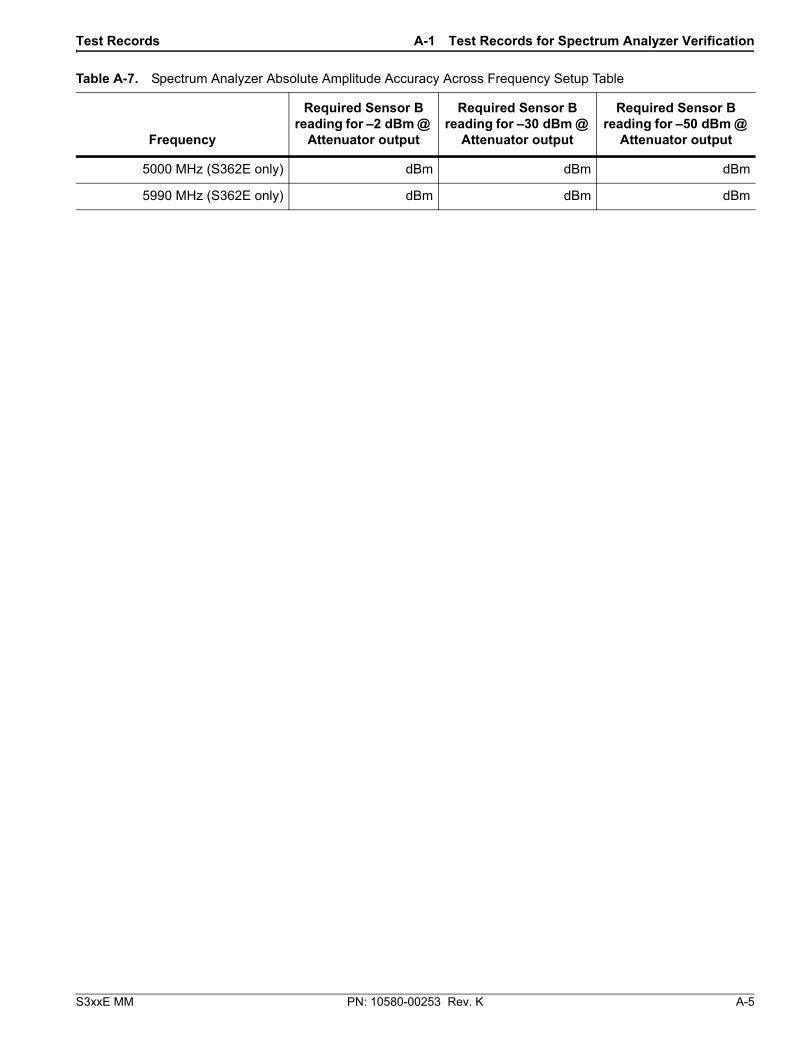
Test Records A-1 Test Records for Spectrum Analyzer Verification
S3xxE MM PN: 10580-00253 Rev. K A-5
5000 MHz (S362E only) dBm dBm dBm
5990 MHz (S362E only) dBm dBm dBm
Table A-7. Spectrum Analyzer Absolute Amplitude Accuracy Across Frequency Setup Table
Frequency
Required Sensor B reading for –2 dBm @
Attenuator output
Required Sensor B reading for –30 dBm @
Attenuator output
Required Sensor B reading for –50 dBm @
Attenuator output

A-1 Test Records for Spectrum Analyzer Verification Test Records
A-6 PN: 10580-00253 Rev. K S3xxE MM
S3____E Firmware Rev: ______________ Operator: _________________ Date: _____________
Serial Number: _______________ Options: ___________________________________________________
Table A-8. Spectrum Analyzer Absolute Amplitude Accuracy Across Frequency (Sheet 1 of 4)
Freq (MHZ)
Input Power (dBm)
Reference Level Setting
(dBm)Atten. Level Setting (dB) Pre-Amp Setting
Marker 1 Reading (dBm)
Spec (dB)
10.1 –50 –40 15 On ±1.25
–30 –20 0 Off ±1.25
–30 –20 5 Off ±1.25
–30 –20 10 Off ±1.25
–30 –20 20 Off ±1.25
–2 0 30 Off ±1.25
–2 0 40 Off ±1.25
–2 0 50 Off ±1.25
–2 0 55 Off ±1.25
50 –50 –40 15 On ±1.25
–30 –20 0 Off ±1.25
–30 –20 5 Off ±1.25
–30 –20 10 Off ±1.25
–30 –20 20 Off ±1.25
–2 0 30 Off ±1.25
–2 0 40 Off ±1.25
–2 0 50 Off ±1.25
–2 0 55 Off ±1.25
S3____E Firmware Rev: ______________ Operator: _________________ Date: _____________
Serial Number: _______________ Options: ___________________________________________________

Test Records A-1 Test Records for Spectrum Analyzer Verification
S3xxE MM PN: 10580-00253 Rev. K A-7
100 –50 –40 15 On ±1.25
–30 –20 0 Off ±1.25
–30 –20 5 Off ±1.25
–30 –20 10 Off ±1.25
–30 –20 20 Off ±1.25
–2 0 30 Off ±1.25
–2 0 40 Off ±1.25
–2 0 50 Off ±1.25
–2 0 55 Off ±1.25
500 –50 –40 15 On ±1.25
–30 –20 0 Off ±1.25
–30 –20 5 Off ±1.25
–30 –20 10 Off ±1.25
–30 –20 20 Off ±1.25
–2 0 30 Off ±1.25
–2 0 40 Off ±1.25
–2 0 50 Off ±1.25
–2 0 55 Off ±1.25
1000 –50 –40 15 On ±1.25
–30 –20 0 Off ±1.25
–30 –20 5 Off ±1.25
–30 –20 10 Off ±1.25
–30 –20 20 Off ±1.25
–2 0 30 Off ±1.25
–2 0 40 Off ±1.25
–2 0 50 Off ±1.25
–2 0 55 Off ±1.25
Table A-8. Spectrum Analyzer Absolute Amplitude Accuracy Across Frequency (Sheet 2 of 4)
Freq (MHZ)
Input Power (dBm)
Reference Level Setting
(dBm)Atten. Level Setting (dB) Pre-Amp Setting
Marker 1 Reading (dBm)
Spec (dB)

A-1 Test Records for Spectrum Analyzer Verification Test Records
A-8 PN: 10580-00253 Rev. K S3xxE MM
2000 –50 –40 15 On ±1.25
–30 –20 0 Off ±1.25
–30 –20 5 Off ±1.25
–30 –20 10 Off ±1.25
–30 –20 20 Off ±1.25
–2 0 30 Off ±1.25
–2 0 40 Off ±1.25
–2 0 50 Off ±1.25
–2 0 55 Off ±1.25
3000 –50 –40 15 On ±1.25
–30 –20 0 Off ±1.25
–30 –20 5 Off ±1.25
–30 –20 10 Off ±1.25
–30 –20 20 Off ±1.25
–2 0 30 Off ±1.25
–2 0 40 Off ±1.25
–2 0 50 Off ±1.25
–2 0 55 Off ±1.25
3990 –50 –40 15 On ±1.25
–30 –20 0 Off ±1.25
–30 –20 5 Off ±1.25
–30 –20 10 Off ±1.25
–30 –20 20 Off ±1.25
–2 0 30 Off ±1.25
–2 0 40 Off ±1.25
–2 0 50 Off ±1.25
–2 0 55 Off ±1.25
Table A-8. Spectrum Analyzer Absolute Amplitude Accuracy Across Frequency (Sheet 3 of 4)
Freq (MHZ)
Input Power (dBm)
Reference Level Setting
(dBm)Atten. Level Setting (dB) Pre-Amp Setting
Marker 1 Reading (dBm)
Spec (dB)

Test Records A-1 Test Records for Spectrum Analyzer Verification
S3xxE MM PN: 10580-00253 Rev. K A-9
5000
(S362E
only)
–50 –40 15 On ±1.50
–30 –20 0 Off ±1.50
–30 –20 5 Off ±1.50
–30 –20 10 Off ±1.50
–30 –20 20 Off ±1.50
–2 0 30 Off ±1.50
–2 0 40 Off ±1.50
–2 0 50 Off ±1.50
–2 0 55 Off ±1.50
5990(S362Eo
nly)
–50 –40 15 On ±1.50
–30 –20 0 Off ±1.50
–30 –20 5 Off ±1.50
–30 –20 10 Off ±1.50
–30 –20 20 Off ±1.50
–2 0 30 Off ±1.50
–2 0 40 Off ±1.50
–2 0 50 Off ±1.50
–2 0 55 Off ±1.50
Table A-8. Spectrum Analyzer Absolute Amplitude Accuracy Across Frequency (Sheet 4 of 4)
Freq (MHZ)
Input Power (dBm)
Reference Level Setting
(dBm)Atten. Level Setting (dB) Pre-Amp Setting
Marker 1 Reading (dBm)
Spec (dB)

A-1 Test Records for Spectrum Analyzer Verification Test Records
A-10 PN: 10580-00253 Rev. K S3xxE MM
S3____E Firmware Rev: ______________ Operator: _________________ Date: _____________
Serial Number: _______________ Options: ___________________________________________________
Table A-9. Spectrum Analyzer Residual Spurious with Preamp Off
Start Freq. Stop Freq. RBW VBW Measured Values Specification
10 MHz 50 MHz 1 kHz 300 Hz dBm ≤ –90 dBm
50 MHz 2.0 GHz 3 kHz 10 kHz dBm ≤ –90 dBm
2.0 GHz 4.0 GHz 1 kHz 1 kHz dBm ≤ –90 dBm
4.0 GHz(S362E only)
5.0 GHz 1 kHz 3 kHz dBm ≤ –90 dBm
5.0 GHz(S362E only)
5.2 GHz 1 kHz 1 kHz dBm ≤ –90 dBm
5.2 GHz(S362E only)
5.7 GHz 300 Hz 3 kHz dBm ≤ –90 dBm
5.7 GHz(S362E only)
5.9 GHz 300 Hz 3 kHz dBm ≤ –90 dBm
5.9 GHz(S362E only)
6.0 GHz 1 kHz 100 Hz dBm ≤ –90 dBm
Table A-10. Spectrum Analyzer Residual Spurious with Preamp On
Start Freq. Stop Freq. Measured Values Specification
10 MHz 1.0 GHz dBm ≤ –90 dBm
1.0 GHz 4.0 GHz dBm ≤ –90 dBm
4.0 GHz (S362E only) 6.0 GHz dBm ≤ –90dBm

Test Records A-1 Test Records for Spectrum Analyzer Verification
S3xxE MM PN: 10580-00253 Rev. K A-11
S3____E Firmware Rev: ______________ Operator: _________________ Date: _____________
Serial Number: _______________ Options: ___________________________________________________
Table A-11. Spectrum Analyzer DANL with Pre Amp Off
Start Freq Stop Freq RBW VBWMeasured Value at
100 kHz RBWCalculated for
10 Hz RBW Specification
10 MHz 2.4 GHz 100 kHz 1 kHz dBm dBm ≤ –131 dBm
2.4 GHz 4.0 GHz 100 kHz 1 kHz dBm dBm ≤ –127 dBm
4.0 GHz(S362E)
5.0 GHz 100 kHz 1 kHz dBm dBm ≤ –124 dBm
5.0 GHz(S362E)
6.0 GHz 100 kHz 1 kHz dBm dBm ≤ –116 dBm
Table A-12. Spectrum Analyzer DANL with Pre Amp On
Start Freq Stop Freq RBW VBWMeasured Value at
100 kHz RBWCalculated for
10 Hz RBW Specification
10 MHz 2.4 GHz 100 kHz 1 kHz dBm dBm ≤ –147 dBm
2.4 GHz 4.0 GHz 100 kHz 1 kHz dBm dBm ≤ –144 dBm
4.0 GHz(S362E)
5.0 GHz 100 kHz 1 kHz dBm dBm ≤ –140 dBm
5.0 GHz(S362E)
6.0 GHz 100 kHz 1 kHz dBm dBm ≤ –133 dBm
Table A-13. Third Order Intercept (TOI) Verification
Frequency Measured Max ValueCalculated TOI
TOI = –20 + [(–20 – max) / 2] Specification
800 MHz dBm dBm ≥ 16 dBm
2400 MHz dBm dBm ≥ 20 dBm

A-2 Test Records for Cable and Antenna Analyzer Verification Test Records
A-12 PN: 10580-00253 Rev. K S3xxE MM
A-2 Test Records for Cable and Antenna Analyzer Verification
S3____E Firmware Rev: ______________ Operator: _________________ Date: _____________
Serial Number: _______________ Options: ___________________________________________________
Table A-14. VNA Frequency Accuracy
Frequency Measured Value Specification
2 GHz (2000 MHz) MHz ± 5.0 kHz (± 2.5 ppm)
Table A-15. VNA Return Loss Accuracy Verification
Return Loss Measured Value Specification
Start Frequency = 2 MHz, Stop Frequency = 4 GHz (S33xE) or 6 GHz (S36xE)
6 dB dB –4.8 dB ≥ x ≥ –7.2 dB
20 dB dB –18.3 dB ≥ x ≥ −21.7 dB

Test Records A-3 Test Records for Options Verification
S3xxE MM PN: 10580-00253 Rev. K A-13
A-3 Test Records for Options Verification
S3____E Firmware Rev: ______________ Operator: _________________ Date: _____________
Serial Number: _______________ Options: ___________________________________________________
Table A-16. Option 10, Bias Tee
Voltage Setting Measured Values
Voltage Specification
Current Specification
105 ohm Load, Low Current
12 V V mA 12 ± 1.2 V 85 mA to 145 mA
18 V V mA 18 ± 1.8 V 142 mA to 202 mA
24 V V mA 24 ± 2.4 V 199 mA to 259 mA
40 ohm Load, High Current
15 V V mA 15 ± 1.5 V 325 mA to 425 mA
78 ohm Load, High Current
32 V V mA 32 ± 3.2 V 370 mA to 450 mA
Table A-17. Option 21, VNA System Dynamic Range Verification
Frequency Measured Value Specification
2 MHz to 4 GHz dB ≤ –80 dB
> 4 GHz to 6 GHz (S36xE) dB ≤ –70 dB

A-3 Test Records for Options Verification Test Records
A-14 PN: 10580-00253 Rev. K S3xxE MM
S3____E Firmware Rev: ______________ Operator: _________________ Date: _____________
Serial Number: _______________ Options: ___________________________________________________
Table A-18. Option 29, Characterization Chart for Power Meter Verification
Test Power Level @ 50 MHz Required Sensor B Reading
0 dBm dBm
–50 dBm dBm
Test Power Level @ 3900 MHz
(S332E only) Required Sensor B Reading
0 dBm dBm
–50 dBm dBm
Test Power Level @ 5900 MHz
(S362E only) Required Sensor B Reading
0 dBm dBm
–50 dBm dBm
Table A-19. Option 29, Internal Power Meter Accuracy Verification
Frequency Input Power Measured Values Specification
50 MHz 0 dBm dBm ± 1.25 dB
–50 dBm dBm ± 1.25 dB
3.9 GHz
(S332E only)
0 dBm dBm ± 1.25 dB
–50 dBm dBm ± 1.25 dB
5.9 GHz
(S362E only)
0 dBm dBm ± 1.50 dB
–50 dBm dBm ± 1.50 dB
Table A-20. Option 31, GPS Receiver Frequency Accuracy Verification
Frequency Measured Value Error Specification
Spectrum Analyzer Frequency Accuracy with GPS High Frequency Accuracy (S332E or S362E only)
4.0 GHz GHz Hz ± 350 Hz (± 50 ppb)
Spectrum Analyzer Frequency Accuracy with Internal High Frequency Accuracy (S332E or S362E only)
4.0 GHz GHz Hz ± 1.2 kHz (± 0.3 ppm)

Test Records A-3 Test Records for Options Verification
S3xxE MM PN: 10580-00253 Rev. K A-15
Table A-21. Option 31, GPS Receiver Bias Tee Verification
Voltage Setting Measured Value Specification
3.3 V mA 32 mA ± 15 % (27.2 mA to 36.8 mA)
5.0 V mA 55.6 mA ± 15 % (47.3 mA to 63.9 mA)

A-3 Test Records for Options Verification Test Records
A-16 PN: 10580-00253 Rev. K S3xxE MM


Anritsu utilizes recycled paper and environmentally conscious inks and toner.
Anritsu Company490 Jarvis Drive
Morgan Hill, CA 95037-2809USA
http://www.anritsu.com