UL Evaluation Report · UL design W419 – System A is similar to design U499 except that steel...
18
UL Evaluation Report UL ER R3501-02 Issued: June 12, 2015 Revised: December 7, 2015 Visit UL’s On-Line Certifications Directory: http://www.ul.com/erdirectory for current status of report. UL Category Code: ULFP CSI MasterFormat® DIVISION: 09 00 00 - FINISHES Sub-level 2: 09 20 00 – Plaster and Gypsum Board Sub-level 3: 09 21 00 – Plaster and Gypsum Board Assemblies Sub-level 4: 09 21 16 – Gypsum Board Assemblies Sub-level 5: 09 21 16.23 – Gypsum Board Shaft Wall Assemblies Sub-level 3: 09 29 00 – Gypsum Board Sub-level 4: 09 29 82 – Gypsum Board Fireproofing COMPANY: National Gypsum Company Technology & Innovation Center 5901 Carnegie Blvd Charlotte, NC 28209-4635 www.NationalGypsum.com 1. SUBJECT: One, Two, Three, and Four-Hour Fire-Resistive Interior Partition Systems One and Two-Hour Ceiling Assemblies Two-Hour Horizontal Membrane and Duct Protection Assemblies The assemblies consist of steel studs and tracks faced with Gold Bond Fire-Shield Shaftliner gypsum board on one side and Gold Bond gypsum board on the other side. Gold Bond Shaftliner Products UL PRODUCT DESIGNATION TRADENAME THICKNESS, inches FSW Gold Bond® Fire-Shield® Shaftliner 1 FSW Gold Bond® Fire-Shield® Shaftliner XP 1 FSW, FSW-7 Gold Bond® Fire-Shield® eXP Shaftliner 1 FSK-C Gold Bond® Kal-Kore® Fire-Shield® Plaster Base C 1/2 or 5/8
Transcript of UL Evaluation Report · UL design W419 – System A is similar to design U499 except that steel...

UL Evaluation Report UL ER R3501-02 Issued: June 12, 2015 Revised: December 7, 2015 Visit UL’s On-Line Certifications Directory: http://www.ul.com/erdirectory for current status of report. UL Category Code: ULFP CSI MasterFormat® DIVISION: 09 00 00 - FINISHES Sub-level 2: 09 20 00 – Plaster and Gypsum Board Sub-level 3: 09 21 00 – Plaster and Gypsum Board Assemblies Sub-level 4: 09 21 16 – Gypsum Board Assemblies Sub-level 5: 09 21 16.23 – Gypsum Board Shaft Wall Assemblies Sub-level 3: 09 29 00 – Gypsum Board Sub-level 4: 09 29 82 – Gypsum Board Fireproofing COMPANY: National Gypsum Company Technology & Innovation Center 5901 Carnegie Blvd Charlotte, NC 28209-4635 www.NationalGypsum.com 1. SUBJECT: One, Two, Three, and Four-Hour Fire-Resistive Interior Partition Systems One and Two-Hour Ceiling Assemblies Two-Hour Horizontal Membrane and Duct Protection Assemblies The assemblies consist of steel studs and tracks faced with Gold Bond Fire-Shield Shaftliner gypsum board on one side and Gold Bond gypsum board on the other side.
Gold Bond Shaftliner Products
UL PRODUCT DESIGNATION
TRADENAME THICKNESS, inches
FSW Gold Bond® Fire-Shield® Shaftliner 1 FSW Gold Bond® Fire-Shield® Shaftliner XP 1
FSW, FSW-7 Gold Bond® Fire-Shield® eXP Shaftliner 1 FSK-C Gold Bond® Kal-Kore® Fire-Shield® Plaster Base C 1/2 or 5/8

Gold Bond Gypsum Board Products
UL PRODUCT DESIGNATION
TRADENAME THICKNESS, inches
FSMR-C Gold Bond® XP® Fire-Shield® C Gypsum Board 1/2 or 5/8 FSW-C Gold Bond® Fire-Shield® C Gypsum Board 1/2 or 5/8
FSK Gold Bond® Kal-Kore® Fire-Shield® Plaster Base 5/8 FSW Gold Bond® Fire-Shield® Gypsum Board 5/8
FSW or FSW-3 Gold Bond® XP® Fire-Shield® Gypsum Board 5/8 FSW-5 Gold Bond® Hi Abuse® XP® Fire-Shield® Gypsum
Board 5/8
FSW-5 Gold Bond® Hi Impact® XP® Fire-Shield® Gypsum Board
5/8
SoundBreak XP Gold Bond® SoundBreak® XP® Gypsum Board 5/8 FSW-6 Gold Bond® eXP® Interior Extreme® Gypsum Panel 5/8 FSW-6 Gold Bond® eXP® Interior Extreme® AR Gypsum Panel 5/8 FSW-6 Gold Bond® eXP® Interior Extreme® IR Gypsum Panel 5/8 FSW-6 Gold Bond® eXP® Fire-Shield® Tile Backer 5/8
2. SCOPE OF EVALUATION Compliance with the following codes: 2006, 2009, 2012, 2015 International Building Code (IBC) 2006, 2009, 2012, 2015 International Residential Code (IRC)
The products were evaluated for the following properties: Fire-resistance-rated construction Structural Physical Properties Surface Burning Characteristics Noncombustibility 3. REFERENCED DOCUMENTS
Acceptance Criteria for Determining Limiting Heights of Composite Walls Constructed of Gypsum Board and Steel Studs, AC86, dated July 1995.
ANSI/UL 263, 14th Ed (ASTM E119), Fire Tests of Building Construction and Materials. ANSI/UL 723, 10th Ed (ASTM E 84), Test for Surface Burning Characteristics of Building Materials. ASTM E 136-12, Standard Test Method for Behavior of Materials in a Vertical Tube Furnace at 750°C. ASTM C1178-08, Standard Specification for Coated Glass Mat Water-Resistant Gypsum Backing Panel. ASTM C1396-13, Standard Specification for Gypsum Board. ASTM C1658-12, 12, Standard Specification for Glass Mat Gypsum Panels ASTM C1766-13, Standard Specification for Factory-Laminated Gypsum Panel Products. AC10, Acceptance Criteria for Quality Documentation, dated June 2014.
Page 2 of 18

4. USES
The Gold Bond® Interior Partition Systems are designed for use where one, two, three, or four-hour fire resistive non-load bearing partitions are required when installed in accordance with 2006 IBC Sections 707.5 and 708.4, 2009 IBC Sections 708.5 and 709.4 and 2012 IBC and 2015 Sections 708.4 and 713. The partitions may be erected from one side and left unfinished on the service equipment or shaft side. When used to enclose stairs or other occupied areas, they may be finished on both sides. The systems consist of 1 inch (25.4 mm) thick Gold Bond® Fire-Shield® Shaftliner and either 5/8 inch (16 mm) thick Gold Bond® Fire-Shield® Gypsum Board or 1/2 inch (13 mm) thick Gold Bond® Fire-Shield® C Gypsum Board, supported by 2-1/2 inch (63.5 mm), 4 inch (102 mm), or 6 inch (152 mm) No. 25 gage [0.020 inch (0.51 mm)] or No. 20 gage [0.033 inch (0.83 mm)] galvanized steel CT, CH, or I-studs, and J-tracks. Allowable partition heights are indicated in Tables 1 and 2, and are based on testing in accordance with the July 1995 edition of AC86.
5. PRODUCT DESCRIPTION
5.1 Steel:
The steel studs are fabricated from galvanized steel complying with ASTM A653 SS Grade 40, with a minimum yield strength of 40,000 psi (275 MPa). The J-tracks are fabricated from galvanized steel complying with ASTM A653 CS Grade 33, with a minimum yield strength of 33,000 psi (228 MPa). Studs and tracks are roll-formed from steel having a minimum design bare-steel thickness of 0.020 inch (0.51 mm) or 0.33 inch (0.83 mm) and a G40 galvanized coating.
5.2 Shaftliner Panels and Gypsum Board Panels:
For the purpose of this report, the trade name or UL product designation for any of the products may be used.
The Shaftliner Panels and Gypsum Board Panels described in this report are recognized as a Class A finish material with a flame spread index of 25 or less and smoke-developed index of 450 or less, when tested in accordance with UL723 (ASTM E84) as set forth in Section 803.1.1 of the 2006, 2009, 2012, or 2015 IBC. These boards, having a noncombustible core of gypsum complying with ASTM E136, are considered a noncombustible material, as described in Section 703.4.2 of the 2006 and 2009 IBC or 703.5.2 of the 2012 and 2015 IBC.
The products described comply with the requirements of ASTM C1396, C1658, C1178 or C1766 as noted below.
Gold Bond Shaftliner Products
Gold Bond Gypsum Board Products
TRADENAME ASTM STANDARD Gold Bond® Kal-Kore® Fire-Shield® Plaster Base C C1396
Gold Bond® XP® Fire-Shield® C Gypsum Board C1396 Gold Bond® Fire-Shield® C Gypsum Board C1396
Gold Bond® Kal-Kore® Fire-Shield® Plaster Base C1396 Gold Bond® Fire-Shield® Gypsum Board C1396
Gold Bond® XP® Fire-Shield® Gypsum Board C1396 Gold Bond® Hi Abuse® XP® Fire-Shield® Gypsum Board C1396 Gold Bond® Hi Impact® XP® Fire-Shield® Gypsum Board C1396
Gold Bond® SoundBreak® XP® Gypsum Board C1766 Gold Bond® eXP® Interior Extreme® Gypsum Panel C1658
Gold Bond® eXP® Interior Extreme® AR Gypsum Panel C1658 Gold Bond® eXP® Interior Extreme® IR Gypsum Panel C1658
Gold Bond® eXP® Fire-Shield® Tile Backer C1178
TRADENAME ASTM STANDARD Gold Bond® Fire-Shield® Shaftliner C1396
Gold Bond® Fire-Shield® Shaftliner XP C1396 Gold Bond® Fire-Shield® eXP Shaftliner C1658
Page 3 of 18
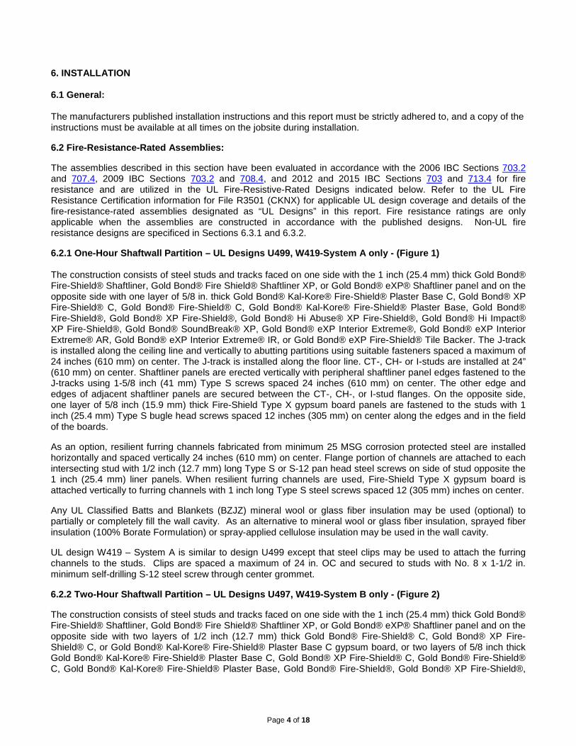
6. INSTALLATION 6.1 General: The manufacturers published installation instructions and this report must be strictly adhered to, and a copy of the instructions must be available at all times on the jobsite during installation.
6.2 Fire-Resistance-Rated Assemblies:
The assemblies described in this section have been evaluated in accordance with the 2006 IBC Sections 703.2 and 707.4, 2009 IBC Sections 703.2 and 708.4, and 2012 and 2015 IBC Sections 703 and 713.4 for fire resistance and are utilized in the UL Fire-Resistive-Rated Designs indicated below. Refer to the UL Fire Resistance Certification information for File R3501 (CKNX) for applicable UL design coverage and details of the fire-resistance-rated assemblies designated as “UL Designs” in this report. Fire resistance ratings are only applicable when the assemblies are constructed in accordance with the published designs. Non-UL fire resistance designs are specificed in Sections 6.3.1 and 6.3.2.
6.2.1 One-Hour Shaftwall Partition – UL Designs U499, W419-System A only - (Figure 1) The construction consists of steel studs and tracks faced on one side with the 1 inch (25.4 mm) thick Gold Bond® Fire-Shield® Shaftliner, Gold Bond® Fire Shield® Shaftliner XP, or Gold Bond® eXP® Shaftliner panel and on the opposite side with one layer of 5/8 in. thick Gold Bond® Kal-Kore® Fire-Shield® Plaster Base C, Gold Bond® XP Fire-Shield® C, Gold Bond® Fire-Shield® C, Gold Bond® Kal-Kore® Fire-Shield® Plaster Base, Gold Bond® Fire-Shield®, Gold Bond® XP Fire-Shield®, Gold Bond® Hi Abuse® XP Fire-Shield®, Gold Bond® Hi Impact® XP Fire-Shield®, Gold Bond® SoundBreak® XP, Gold Bond® eXP Interior Extreme®, Gold Bond® eXP Interior Extreme® AR, Gold Bond® eXP Interior Extreme® IR, or Gold Bond® eXP Fire-Shield® Tile Backer. The J-track is installed along the ceiling line and vertically to abutting partitions using suitable fasteners spaced a maximum of 24 inches (610 mm) on center. The J-track is installed along the floor line. CT-, CH- or I-studs are installed at 24” (610 mm) on center. Shaftliner panels are erected vertically with peripheral shaftliner panel edges fastened to the J-tracks using 1-5/8 inch (41 mm) Type S screws spaced 24 inches (610 mm) on center. The other edge and edges of adjacent shaftliner panels are secured between the CT-, CH-, or I-stud flanges. On the opposite side, one layer of 5/8 inch (15.9 mm) thick Fire-Shield Type X gypsum board panels are fastened to the studs with 1 inch (25.4 mm) Type S bugle head screws spaced 12 inches (305 mm) on center along the edges and in the field of the boards.
As an option, resilient furring channels fabricated from minimum 25 MSG corrosion protected steel are installed horizontally and spaced vertically 24 inches (610 mm) on center. Flange portion of channels are attached to each intersecting stud with 1/2 inch (12.7 mm) long Type S or S-12 pan head steel screws on side of stud opposite the 1 inch (25.4 mm) liner panels. When resilient furring channels are used, Fire-Shield Type X gypsum board is attached vertically to furring channels with 1 inch long Type S steel screws spaced 12 (305 mm) inches on center.
Any UL Classified Batts and Blankets (BZJZ) mineral wool or glass fiber insulation may be used (optional) to partially or completely fill the wall cavity. As an alternative to mineral wool or glass fiber insulation, sprayed fiber insulation (100% Borate Formulation) or spray-applied cellulose insulation may be used in the wall cavity.
UL design W419 – System A is similar to design U499 except that steel clips may be used to attach the furring channels to the studs. Clips are spaced a maximum of 24 in. OC and secured to studs with No. 8 x 1-1/2 in. minimum self-drilling S-12 steel screw through center grommet.
6.2.2 Two-Hour Shaftwall Partition – UL Designs U497, W419-System B only - (Figure 2)
The construction consists of steel studs and tracks faced on one side with the 1 inch (25.4 mm) thick Gold Bond® Fire-Shield® Shaftliner, Gold Bond® Fire Shield® Shaftliner XP, or Gold Bond® eXP® Shaftliner panel and on the opposite side with two layers of 1/2 inch (12.7 mm) thick Gold Bond® Fire-Shield® C, Gold Bond® XP Fire-Shield® C, or Gold Bond® Kal-Kore® Fire-Shield® Plaster Base C gypsum board, or two layers of 5/8 inch thick Gold Bond® Kal-Kore® Fire-Shield® Plaster Base C, Gold Bond® XP Fire-Shield® C, Gold Bond® Fire-Shield® C, Gold Bond® Kal-Kore® Fire-Shield® Plaster Base, Gold Bond® Fire-Shield®, Gold Bond® XP Fire-Shield®,
Page 4 of 18

Gold Bond® Hi Abuse® XP Fire-Shield®, Gold Bond® Hi Impact® XP Fire-Shield®, Gold Bond® eXP Interior Extreme®, Gold Bond® eXP Interior Extreme® AR, Gold Bond® eXP Interior Extreme® IR, or Gold Bond® eXP Fire-Shield® Tile Backer. The J-track is installed along the ceiling line and vertically to abutting partitions using suitable fasteners spaced a maximum of 24 inches (610 mm) on center. The J-track is installed along the floor line. CT-, CH- or I-studs are installed at 24 inches (610 mm) on center. Shaftliner panels are erected vertically with peripheral shaftliner panel edges fastened to the J-tracks using 1-5/16 inch (33 mm) Type S screws spaced 24 inches (610 mm) on center. The other edge and edges of adjacent shaftliner panels are secured between the CT-, CH- or I-stud flanges. On the opposite side, two layers of 1/2 inch (12.7 mm) thick Gold Bond® Fire-Shield® C, Gold Bond® XP Fire-Shield® C, or Gold Bond® Kal-Kore® Fire-Shield® Plaster Base C gypsum board panels, or two layers of 5/8 in. thick Gold Bond® Kal-Kore® Fire-Shield® Plaster Base C, Gold Bond® XP Fire-Shield® C, Gold Bond® Fire-Shield® C, Gold Bond® Kal-Kore® Fire-Shield® Plaster Base, Gold Bond® Fire-Shield®, Gold Bond® XP Fire-Shield®, Gold Bond® Hi Abuse® XP Fire-Shield®, Gold Bond® Hi Impact® XP Fire-Shield®, Gold Bond® eXP Interior Extreme®, Gold Bond® eXP Interior Extreme® AR, Gold Bond® eXP Interior Extreme® IR, or Gold Bond® eXP Fire-Shield® Tile Backer are fastened to the studs with the base layer installed vertically and fastened to the studs and tracks using 1 inch (25.4 mm) long Type S bugle head screws spaced 24 inches (610 mm) on center. The face layer is installed vertically over the base layer and fastened to the stud framing using 1-5/8 inch (41 mm) long Type S screws spaced 12 inches (305 mm) on center. Joints between base and face layers are staggered 24 inches (610 mm) horizontally and 12 inches (305 mm) vertically. Face layer joints covered with tape and joint compound. Exposed screw heads covered with joint compound.
As an option, resilient furring channels fabricated from minimum 25 MSG corrosion protected steel are installed horizontally and spaced vertically 24 inches (610 mm) on center. Flange portion of channels are attached to each intersecting stud with 1/2 inch (12.7 mm) long Type S or S-12 pan head steel screws on side of stud opposite the 1 inch (25.4 mm) liner panels. When resilient furring channels are used, the base layer is attached vertically to furring channels with 1 inch (25.4 mm) long Type S steel screws spaced 24 inches (610 mm) on center. The face layer is attached vertically and fastened to furring channels with 1-5/8 inch (25.4 mm) long Type S steel screws spaced 24 inches (610 mm) on center.
Any UL Classified Batts and Blankets (BZJZ) mineral wool or glass fiber insulation may be used (optional) to partially or completely fill the wall cavity. UL design W419 – System B is similar to design U497 except it allows the substitution of 2 layers of 5/16 inch (7.9 mm) thick gypsum board of the same types noted above in place of one layer of 5/8 inch (15.9 mm) thick gypsum board installed either vertically or horizontally. Horizontal joints on the same side need not be staggered. Inner layer of each double 5/16 inch (7.9 mm) thick layer is attached with fasteners as described above and spaced a maximum of 24 inches (610 mm) on center. 6.2.3 Two-Hour Shaftwall Partition (Finished Both Sides) – UL Designs U498, W419-System C only - (Figure 3)
The construction consists of steel studs and tracks faced on one side with the 1 inch (25.4 mm) thick Gold Bond® Fire-Shield® Shaftliner, Gold Bond® Fire Shield® Shaftliner XP, or Gold Bond® eXP® Shaftliner panel and one layer of 1/2 inch (12.7 mm) thick Gold Bond® Fire-Shield® C, Gold Bond® XP Fire-Shield® C, or Gold Bond® Kal-Kore® Fire-Shield® Plaster Base C gypsum board, or one layer of 5/8 inch thick Gold Bond® Kal-Kore® Fire-Shield® Plaster Base C, Gold Bond® XP Fire-Shield® C, Gold Bond® Fire-Shield® C, Gold Bond® Kal-Kore® Fire-Shield® Plaster Base, Gold Bond® Fire-Shield®, Gold Bond® XP Fire-Shield®, Gold Bond® Hi Abuse® XP Fire-Shield®, Gold Bond® Hi Impact® XP Fire-Shield®, Gold Bond® eXP Interior Extreme®, Gold Bond® eXP Interior Extreme® AR, Gold Bond® eXP Interior Extreme® IR, or Gold Bond® eXP Fire-Shield® Tile Backer gypsum board fastened to steel framing using 2-5/8 in. long Type S bugle head screws spaced 12 in. (305 mm) on centers. The J-track is installed along the ceiling line and vertically to abutting partitions using suitable fasteners spaced a maximum of 24 inches (610 mm) on center. The J-track is installed along the floor line. CT-, CH- or I-studs are installed at 24” (610 mm) on center. Shaftliner panels are erected vertically with peripheral shaftliner panel edges fastened to the J-tracks using 1-5/8 inch (41 mm) Type S screws spaced 24 inches (610 mm) on center. The other edge and edges of adjacent shaftliner panels are secured between the CT-, CH- or I-stud flanges. On each side, one layer of 1/2 inch (12.7 mm) thick Gold Bond® Fire-Shield® C, Gold Bond® XP Fire-Shield® C, or Gold Bond® Kal-Kore® Fire-Shield® Plaster Base C gypsum board, or one layer of 5/8 inch
Page 5 of 18

thick Gold Bond® Kal-Kore® Fire-Shield® Plaster Base C, Gold Bond® XP Fire-Shield® C, Gold Bond® Fire-Shield® C, Gold Bond® Kal-Kore® Fire-Shield® Plaster Base, Gold Bond® Fire-Shield®, Gold Bond® XP Fire-Shield®, Gold Bond® Hi Abuse® XP Fire-Shield®, Gold Bond® Hi Impact® XP Fire-Shield®, Gold Bond® eXP Interior Extreme®, Gold Bond® eXP Interior Extreme® AR, Gold Bond® eXP Interior Extreme® IR, or Gold Bond® eXP Fire-Shield® Tile Backer gypsum board panels are installed horizontally or vertically over the studs and fastened to the studs and tracks using 1 inch (25.4 mm) long Type S bugle head screws spaced 12 inches (305 mm) on center. Face layer joints are staggered horizontally 24 inches (610 mm) on each side of the wall. Face layer joints covered with tape and joint compound. Exposed screw heads covered with joint compound.
As an option, resilient furring channels fabricated from minimum 25 MSG corrosion protected steel are installed horizontally and spaced vertically 24 inches (610 mm) on center. Flange portion of channels are attached to each intersecting stud with 1/2 inch (12.7 mm) long Type S or S-12 pan head steel screws on side of stud opposite the 1 inch (25.4 mm) liner panels. When resilient furring channels are used, the base layer is attached vertically to furring channels with 1 inch long Type S steel screws spaced 12 (305 mm) inches on center.
Any UL Classified Batts and Blankets (BZJZ) mineral wool or glass fiber insulation may be used (optional) to partially or completely fill the wall cavity. As an alternative to mineral wool or glass fiber insulation, sprayed fiber insulation (100% Borate Formulation) or spray-applied cellulose insulation may be used in the wall cavity.
6.2.4 Three-Hour Shaftwall Partition – UL Designs W414, W419-System D only (Figure 4)
The construction consists of steel studs and tracks faced on one side with the 1 inch (25.4 mm) thick Gold Bond® Fire-Shield® Shaftliner, Gold Bond® Fire Shield® Shaftliner XP, or Gold Bond® eXP® Shaftliner panel and on the opposite side with three layers of 5/8 inch (15.9 mm) thick Gold Bond® Kal-Kore® Fire-Shield® Plaster Base C or Gold Bond® Fire-Shield® C gypsum board. The J-track is installed along the ceiling line and vertically to abutting partitions using suitable fasteners spaced a maximum of 24 inches (610 mm) on center. The J-track is installed along the floor line. CT-, CH- or I-studs are installed at 24 inches (610 mm) on center. Shaftliner panels are erected vertically with peripheral shaftliner panel edges fastened to the J-tracks using 1-5/8 inch (41 mm) Type S screws spaced 12 inches (305 mm) on center. The other edge and edges of adjacent shaftliner panels are secured between the CT-, CH- or I-stud flanges. On the opposite side, three layers of 5/8 inch (15.9 mm) thick Gold Bond® Kal-Kore® Fire-Shield® Plaster Base C or Gold Bond® Fire-Shield® C gypsum board panels are installed vertically over the studs with joints staggered 24 inches (610 mm) horizontally. The base layer is fastened to the studs and tracks using 1 inch (25.4 mm) long Type S bugle head screws spaced 24 inches (610 mm) on center at the perimeter and in the field. The second layer is fastened to the studs with 1-5/8 inch (41.3 mm) long Type S bugle head steel screws spaced 12 inches (305 mm) on center at the perimeter and in the field. Joints in second layer are fastened to the base layer of gypsum board with 1-1/2 inch (38.1 mm) long Type G screws spaced 12 inches (305 mm) on center vertically 2 inches (51 mm) from each side of the joint. The face layer is fastened to the studs with 2-1/4 inch (57.1 mm) long Type S bugle head screws spaced 12 inches (305 mm) on center and staggered 6 inches so as not to hit the screws in the previous layer. Joints in the third layer are fastened to inner layers with 1-1/2 inch (38.1 mm) long Type G screws spaced 12 inches (305 mm) on center vertically 2 inches (51 mm) from each side of the joint. Face layer joints covered with tape and joint compound. Exposed screw heads covered with joint compound. 6.2.5 Four-Hour Shaftwall Partition – UL Designs V451, W419-System E only (Figure 5)
The construction consists of steel studs and tracks faced on one side with the 1 inch (25.4 mm) thick Gold Bond® Fire-Shield® Shaftliner, Gold Bond® Fire Shield® Shaftliner XP, or Gold Bond® eXP® Shaftliner panel and on the opposite side with five layers of 5/8 inch (15.9 mm) thick Gold Bond® Kal-Kore® Fire-Shield® Plaster Base C or Gold Bond® Fire-Shield® C gypsum board. The J-track is installed along the ceiling line and vertically to abutting partitions using suitable fasteners spaced a maximum of 24 inches (610 mm) on center. The J-track is installed along the floor line. CT-, CH- or I-studs are installed at 24 inches (610 mm) on center. Shaftliner panels are erected vertically with peripheral shaftliner panel edges fastened to the J-tracks using 1-5/8 inch (41 mm) Type S screws spaced 24 inches (610 mm) on center. The other edge and edges of adjacent shaftliner panels are secured between the CT-, CH- or I-stud flanges. On the opposite side, five layers of 5/8 inch (15.9 mm) thick Gold Bond® Kal-Kore® Fire-Shield® Plaster Base C or Gold Bond® Fire-Shield® C gypsum board panels are installed vertically over the studs with joints staggered 24 inches (610 mm) horizontally. The base layer is fastened to the studs and tracks using 1-1/8 inch (28.5 mm) long Type S bugle head screws spaced 12 inches (610 mm) on
Page 6 of 18

center. The second layer is fastened to the studs with 1-5/8 inch (41.3 mm) long Type S bugle head steel screws spaced 12 inches (305 mm) on center. Butt joints in second layer are fastened to the base layer of gypsum board with 1-1/2 inch (38.1 mm) long Type G screws spaced 8 inches (203 mm) on each side of the joint. The third layer is fastened to studs with 2-1/4 inch long Type S bugle head screws spaced 12 inches on center. The third layer is fastened to inner layers with 1-1/2 inch long Type G screws space 12 inches on center vertically centered between the studs. Butt joints in the third layer are fastened to inner layers with 1-1/2 inch long Type G bugle head screws spaced 8 inches on center on both sides of the joint. Minimum 22 MSG galvanized steel hat-shaped furring channels spaced 16 inches on center are fastened to studs with 2-1/4 inch long Type S bugle head steel screws. Screws alternate from top to bottom flange at each stud intersection. The fourth layer is fastened to the furring channels with 1-1/8 inch long Type S bugle head steel screws spaced 12 inches (305 mm) on center. Butt joints in fourth layer shall be centered over furring channels and fastened with 1-1/8 inch long Type S bugle head screws spaced 8 inches on center on both sides of the joint. The face layer is fastened to the furring channels with 1-5/8 inch long Type S bugle head screws spaced 12 inches (305 mm) on center. The face layer is also fastened to the fourth layer with 1-1/2 inch long Type G screws spaced 16 inches on center along the vertical joints centered between the furring channels. Butt joints in the face layer are centered over the furring channels and fastened with 1-5/8 inch long Type S bugle head screws spaced 8 inches on center on both sides of the joint. Screws and butt joints are staggered. Face layer joints covered with tape and joint compound. Exposed screw heads covered with joint compound.
UL design V451 is identical to design W419 – System E except on the opposite side, five layers of 5/8 inch (15.9 mm) thick Gold Bond® Fire-Shield® C gypsum board panels are installed vertically over the studs with joints staggered 24 inches (610 mm) horizontally.
6.3 Ceiling and Horizontal Applications
6.3.1 One- and Two-Hour Ceilings or Underside of Stair Application (Figure 6)
The system provides fire-resistive protection on corridor ceilings and on the underside of stairs. The I-stud system, as described in section 6.2.1 for one-hour construction and in section 6.2.2 for two-hour construction, is installed in a horizontal orientation. The I-studs are supported by J-tracks that are attached to existing vertical wall framing members using mechanical fasteners spaced a maximum of 24 inches (610 mm) on center. The fasteners must have a minimum allowable load of 200 pounds (889.6 N) in shear or pullout. The I-studs are attached to the J-tracks at each end using two 1/2 inch (12.7 mm) Type S pan head screws. Maximum horizontal spans are noted in Table 3.
6.3.2 Two-Hour Ceiling, Horizontal Membrane and Duct Protection (Figure 7)
The test was conducted in accordance with the method specified ASTM E119-83, except for the sample size. The assembly constructed measured 6 ft. 6 in. by 6 ft. 6 in. (2 m by 2 m)) and was exposed to the fire over an area of 5 ft. 4 in. by 5 ft. 4 in. (1.6 m by 1.6 m). The standard specifies that the area exposed to the fire shall not be less than 180 ft2 with neither dimension less than 12 ft. (3.66 m). The J-track and I-stud systems are installed in a horizontal orientation as described for two-hour construction in section 6.2.2 except three layers of 1/2 inch (12.7 mm) Fire-Shield C gypsum board are attached to the open stud face side. The base and middle layers are applied parallel to the stud framing with edge joints offset one stud cavity. The base layer is fastened to studs with 1 inch (25.4 mm) long Type S screws spaced 24 inches (610 mm) on center. The middle layer is fastened to the studs with 1-5/8 inch (41 mm) long Type S screws spaced 24 inches (610 mm) on center. The face layer is applied perpendicular to the stud framing with butt joints between studs. Face layer fastened to studs with 2-1/4 inch (57 mm) type S screws spaced 12 inches (305 mm) on center. Butt joints are fastened to inner layers with 1-1/2 inch (38 mm) long Type G screws spaced 8 inches (203 mm) on center. Face layer joints and screw heads may be exposed or sealed with a joint tape system.
6.3.3 Two-Hour Ceiling, Horizontal Membrane and Duct Protection UL Design G586 (Figures 7 & 8)
Page 7 of 18

The construction consists of steel studs, C-Channels and J-tracks faced on one side with the 1 inch (25.4 mm) thick Gold Bond® Fire-Shield® Shaftliner, Gold Bond® Fire Shield® Shaftliner XP, or Gold Bond® eXP® Shaftliner panel and on the opposite side with three layers of 5/8 inch (15.9 mm) thick Gold Bond® Fire-Shield® C gypsum board. The steel studs are C-T shaped and measure nominally 1-1/2 in. (38 mm) wide by 4 in.(101 mm) deep and are fabricated from No. 20 MSG galvanized steel. Studs fit into J-track and fastened at top and bottom with 1/2 in. (12.7 mm) Type S screws. “T” shaped section of the studs face upward for installation of gypsum board shaftliner panels. “C” shaped section of studs face downward for attachment of gypsum board. Bottom screws fastened through bottom leg of J-track into stud. Top screws fastened through top of studs into top leg of J-track. Shaftliner panels measuring 1 in. (25.4 mm) thick and supplied in 24 in. (610 mm) widths. The panels are cut 1 in. (25.4 mm) less that the J-track to J-track spacing. The long edges of the shaftliner panels are inserted into the T-shaped section of the C-T studs. The corners of the panels are secured to the J-tracks using 1-5/8 in. (41 mm) Type S screws. On the opposite side, 5/8 inch (15.9 mm) thick Gold Bond® Fire-Shield® C gypsum board panels are installed in three layers. The base layer is installed with the long direction perpendicular to the direction of the studs with 1 in. (25.4 mm) Type S screws spaced 12 in.(305 mm) on center, starting 1-1/2 in. (38 mm) from the side joints. Butt joint screws are placed 1/2 in. (12.7 mm) from joint edge. The second layer is attached with the long direction perpendicular to the direction of the studs with the side joints staggered a minimum of 24 in. (610 mm) from the base layer. The second layer is attached using 1-5/8 in. (41 mm) Type S screws spaced 12 in. (305 mm) on center starting 1-1/2 in. (38 mm) and then 6 in. (152 mm) from the side joints. The butt joint screws are placed 1/2 in. (12.7 mm) from joint edge and staggered a minimum of 24 in. (610 mm) from base layer. Face layer is attached with long dimension parallel to the direction of the studs with 2-1/4 in. (57 mm) Type S screws spaced 12 in. (305 mm) on center starting 1/2 in. (12.7 mm) and then 3 in. (76 mm) from butt joints. The side joint screws are 1-1/2 in. ( 38 mm) from joint edges.
Maximum unsupported length of studs not to exceed 96 in. (2.4 m). When spans exceed 96 inches, a splice shall be constructed using minimum 6 in. (152 mm) deep, minimum 1-1/4 in. (32 mm) legs C-Channels fabricated from No. 25 MSG galvanized steel. The C-Channels are attached to minimum 8 gauge steel hanger wire hung through holes in the C-Channel. The hanger wire is spaced nominally 24 in. (610 mm) on center. The J-track is formed from No. 20 MSG galvanized steel and is used to support the C-T studs. The J-track is secured to both sides of the C-Channel and edges of the adjacent wall assembly so that the 2 in. (51 mm) leg is on top and the 1 in. (25.4 mm) leg is on the bottom facing the finished gypsum side of the ceiling, and flush with the bottom leg of the C-Channel. The J-track is secured to the C-Channel and wall assembly with 1/2 in. (12.7 mm) Type S screws spaced 24 in. (610 mm) on center along centerline of the J-tracks. Where the J-tracks form a butt joint, screws are placed at both the top and bottom of both sides of the butt joint. Nominal 2 in. (51 mm) thick by 6 in. (152 mm) wide mineral wool glued to surface of gypsum board on both sides and across full length of C-Channel with construction adhesive.
7. CONDITIONS OF USE
7.1 General:
The Shaftliner Gypsum Panels and Gypsum Board products described in sections 5.2 of this report, comply with, or are suitable alternatives to what is specified in, those codes listed in section 2.0 of this report, subject to the following conditions:
7.2 The products must be manufactured, identified, and installed in accordance with this report, the manufacturer’s published installation instructions, and the applicable code. If there is a conflict between the manufacturers published installation instructions and this report, this report governs.
7.3 All fire resistive assemblies shall be built in accordance with the applicable published UL design(s) or as otherwise described within this report.
7.4 Studs are manufactured by one of the following:
Page 8 of 18

1. ClarkDietrich Building Systems 2. Marino\WARE 3. SCAFCO 4. CEMCO
7.5 See UL Online Certifications Directory for products evaluated as a part of fire-resistance-rated assemblies in accordance with UL263, Gypsum Board (CKNX).
7.6 See UL Online Certifications Directory for products evaluated for Surface Burning Characteristics in accordance with UL723, Gypsum Board (BWFR).
7.7 The Shaftliner, gypsum panels and gypsum board products described in this report are manufactured by National Gypsum Company, located at the manufacturing locations named below, under the UL LLC Classification and Follow-Up Service Program, which includes inspections in accordance with the quality elements of ICC-ES Acceptance Criteria for Quality Documentation, AC10.
Manufacturing locations: Gibsonton, FL Burlington, NJ Baltimore, MD Ft. Dodge, IA Medicine Lodge, KS Long Beach, CA Mt. Holly, NC National City, MI Phoenix, AZ Portsmouth, NH Richmond, CA Rotan, TX Garden City, GA Shippingport, PA Shoals, IN Waukegan, IL Westwego, LA
8. SUPPORTING EVIDENCE
8.1 Manufacturer’s product literature and quality documentation.
8.2 Reports in accordance with AC86, Acceptance Criteria for Determining Limiting Heights of Composite Walls Constructed of Gypsum Board and Steel Studs, dated July 1995.
8.3 UL Classification reports in accordance with UL263 (ASTM E119). See UL Product Certification Category for Gypsum Board (CKNX).
8.4 Reports in accordance ASTM E119 for Horizontal Membrane and Duct Protection
8.5 UL Classification reports in accordance with UL723 (ASTM E84). See UL Product Certification Categories, Gypsum Board (BWFR).
8.6 Reports in accordance with ASTM C1396, C1177, C1658 and C1766.
8.7 Reports in accordance with ASTM E136.
9. IDENTIFICATION
Page 9 of 18
The gypsum board products described in section 5.2 of this evaluation report are identified by a marking bearing the report holder’s name (National Gypsum Company), the plant identification, the product designation, and the UL Classification Mark. Gold Bond Shaftliner products are also identified with the evaluation report number UL ER3501-02. The validity of the evaluation report is contingent upon this identification appearing on the product. Each stud member as described in this evaluation report is identified by the manufacturer’s name, the steel thickness, and the yield strength.
10. USE OF UL EVALUATION REPORT
10.1 The approval of building products, materials or systems is under the responsibility of the applicable authorities having jurisdiction.
10.2 UL Evaluation Reports shall not be used in any manner that implies an endorsement of the product, material or system by UL.
10.3 The current status of this report, as well as a complete directory of UL Evaluation Reports may be found at UL.com via UL Online Certifications Directory: www.ul.com/erdirectory
Page 10 of 18

FIGURE 1 FIGURE 2
FIGURE 3 FIGURE 4
Page 11 of 18

FIGURE 5
FIGURE 6
Page 12 of 18
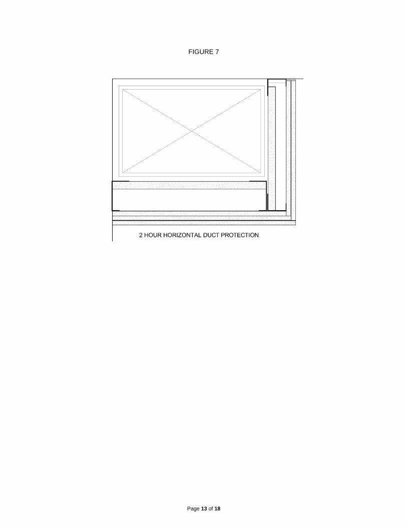
FIGURE 7
Page 13 of 18

Page 14 of 18
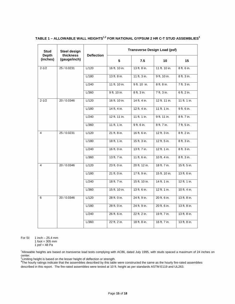
TABLE 1 – ALLOWABLE WALL HEIGHTS1,2 FOR NATIONAL GYPSUM 2 HR C-T STUD ASSEMBLIES3
Stud Depth
(inches)
Steel design thickness
(gauge/inch) Deflection
Transverse Design Load (psf)
5 7.5 10 15
2-1/2 25 / 0.0231 L/120 16 ft. 10 in. 13 ft. 8 in. 11 ft. 10 in. 8 ft. 6 in.
L/180 13 ft. 8 in. 11 ft. 3 in. 9 ft. 10 in. 8 ft. 3 in.
L/240 11 ft. 10 in. 9 ft. 10 in. 8 ft. 8 in. 7 ft. 3 in.
L/360 9 ft. 10 in. 8 ft. 3 in. 7 ft. 3 in. 6 ft. 2 in.
2-1/2 20 / 0.0346 L/120 16 ft. 10 in. 14 ft. 4 in. 12 ft. 11 in. 11 ft. 1 in.
L/180 14 ft. 4 in. 12 ft. 4 in. 11 ft. 1 in. 9 ft. 6 in.
L/240 12 ft. 11 in. 11 ft. 1 in. 9 ft. 11 in. 8 ft. 7 in.
L/360 11 ft. 1 in. 9 ft. 6 in. 8 ft. 7 in. 7 ft. 5 in.
4 25 / 0.0231 L/120 21 ft. 8 in. 16 ft. 6 in. 12 ft. 3 in. 8 ft. 2 in.
L/180 18 ft. 1 in. 15 ft. 3 in. 12 ft. 5 in. 8 ft. 3 in.
L/240 16 ft. 0 in. 13 ft. 7 in. 12 ft. 1 in. 8 ft. 3 in.
L/360 13 ft. 7 in. 11 ft. 6 in. 10 ft. 4 in. 8 ft. 3 in.
4 20 / 0.0346 L/120 23 ft. 0 in. 20 ft. 12 in. 18 ft. 7 in. 15 ft. 5 in.
L/180 21 ft. 0 in. 17 ft. 9 in. 15 ft. 10 in. 13 ft. 6 in.
L/240 18 ft. 7 in. 15 ft. 10 in. 14 ft. 1 in. 12 ft. 1 in.
L/360 15 ft. 10 in. 13 ft. 6 in. 12 ft. 1 in. 10 ft. 4 in.
6 20 / 0.0346 L/120 28 ft. 0 in. 24 ft. 9 in. 20 ft. 6 in. 13 ft. 8 in.
L/180 28 ft. 0 in. 24 ft. 9 in. 20 ft. 6 in. 13 ft. 8 in.
L/240 26 ft. 6 in. 22 ft. 2 in. 19 ft. 7 in. 13 ft. 8 in.
L/360 22 ft. 2 in. 18 ft. 8 in. 16 ft. 7 in. 13 ft. 8 in.
For SI: 1 inch – 25.4 mm 1 foot = 305 mm 1 psf = 48 Pa 1Allowable heights are based on transverse load tests complying with AC86, dated July 1995, with studs spaced a maximum of 24 inches on center. 2Limiting height is based on the lesser height of deflection or strength. 3The hourly ratings indicate that the assemblies described by this table were constructed the same as the hourly fire-rated assemblies described in this report. The fire-rated assemblies were tested at 10 ft. height as per standards ASTM E119 and UL263.
Page 15 of 18

TABLE 2 – ALLOWABLE WALL HEIGHTS1,2 FOR NATIONAL GYPSUM 1- and 2 HR I-STUD ASSEMBLIES3
Wall System
Steel thickness
(gage/inch) Deflection
Transverse Design Load (psf)
5 7.5 10 15
1 hour 2-1/2 in. Shaftwall
25 / 0.0183 L/120
13 ft. 4 in. 11 ft. 7 in. 10 ft. 1 in. 8 ft. 3 in.
L/240
10 ft. 7 in. 9 ft. 3 in. 8 ft. 5 in. 7 ft. 4 in.
L/360
9 ft. 3 in. 8 ft. 11 in. 7 ft. 4 in. 6 ft. 5 in.
1 hour 2-1/2 in. Shaftwall
20 / 0.0325 L/120
15 ft. 2 in. 13 ft. 3 in. 12 ft. 1 in. 10 ft. 7 in.
L/240
12 ft. 1 in. 10 ft. 7 in. 9 ft. 7 in. 8 ft. 4 in.
L/360
10 ft. 7 in. 9 ft. 2 in. 8 ft. 4 in. 7 ft. 4 in.
1 hour 4 in.
Shaftwall
25 / 0.0183 L/120
17 ft. 11 in. 14 ft. 10 in. 12 ft. 10 in. 9 ft. 9 in.
L/240
14 ft. 3 in. 12 ft. 5 in. 11 ft. 4 in. 9 ft. 5 in.
L/360
12 ft. 5 in. 10 ft. 10 in. 9 ft. 5 in. 8 ft. 3 in.
1 hour 4 in.
Shaftwall
20 / 0.0325 L/120
20 ft. 0 in. 18 ft. 2 in. 16 ft. 6 in. 14 ft. 3 in.
L/240
16 ft. 6 in. 14 ft. 5 in. 13 ft. 1 in. 11 ft. 5 in.
L/360
14 ft. 5 in. 12 ft. 7 in. 11 ft. 5 in. 9 ft. 4 in.
1 hour 6 in.
Shaftwall
20 / 0.0325 L/120
24 ft. 0 in. 22 ft. 10 in. 19 ft. 9 in. 16 ft. 2 in.
L/240
20 ft. 11 in. 18 ft. 4 in. 16 ft. 8 in. 14 ft. 6 in.
L/360
18 ft. 4 in. 16 ft. 0 in. 14 ft. 6 in. 10 ft. 11 in.
2 hour 2-1/2 in. Shaftwall
25 / 0.0183 L/120
14 ft. 7 in. 12 ft. 4 in. 10 ft. 9 in. 8 ft. 9 in.
L/240
11 ft. 7 in. 10 ft. 1 in. 9 ft. 2 in. 8 ft. 0 in.
L/360
10 ft. 1 in. 8 ft. 10 in. 8 ft. 0 in. 7 ft. 0 in.
2 hour 2-1/2 in. Shaftwall
20 / 0.0325 L/120
17 ft. 9 in. 15 ft. 6 in. 14 ft. 1 in. 12 ft. 4 in.
L/240
14 ft. 1 in. 12 ft. 4 in. 11 ft. 2 in. 8 ft. 9 in.
L/360
12 ft. 4 in. 9 ft. 8 in. 8 ft. 9 in. 7 ft. 8 in.
2 hour 4 in.
Shaftwall
25 / 0.0183
L/120
19 ft. 10 in. 16 ft. 3 in. 14 ft. 0 in. 10 ft. 2 in.
L/240
16 ft. 2 in. 14 ft. 2 in. 11 ft. 6 in. 10 ft. 0 in.
L/360
14 ft. 2 in. 11 ft. 0 in. 10 ft. 0 in. 8 ft. 9 in.
2 hour 4 in.
Shaftwall
20 / 0.0325 L/120
23 ft. 2 in. 20 ft. 2 in. 18 ft. 1 in. 14 ft. 9 in.
L/240
18 ft. 4 in. 16 ft. 1 in. 14 ft. 7 in. 11 ft. 1 in.
L/360
16 ft. 1 in. 14 ft. 0 in. 11 ft. 1 in. 9 ft. 8 in.
Page 16 of 18
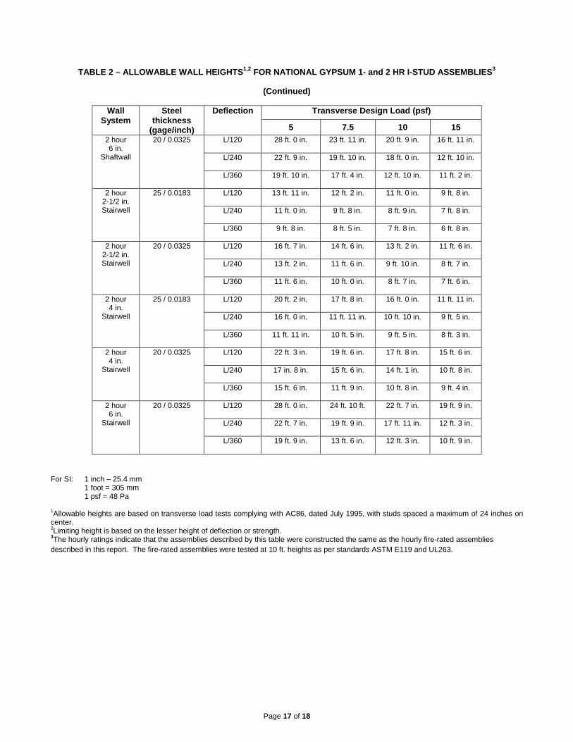
TABLE 2 – ALLOWABLE WALL HEIGHTS1,2 FOR NATIONAL GYPSUM 1- and 2 HR I-STUD ASSEMBLIES3
(Continued)
Wall System
Steel thickness
(gage/inch)
Deflection Transverse Design Load (psf)
5 7.5 10 15 2 hour 6 in.
Shaftwall
20 / 0.0325 L/120
28 ft. 0 in. 23 ft. 11 in. 20 ft. 9 in. 16 ft. 11 in.
L/240
22 ft. 9 in. 19 ft. 10 in. 18 ft. 0 in. 12 ft. 10 in.
L/360
19 ft. 10 in. 17 ft. 4 in. 12 ft. 10 in. 11 ft. 2 in.
2 hour 2-1/2 in. Stairwell
25 / 0.0183 L/120
13 ft. 11 in. 12 ft. 2 in. 11 ft. 0 in. 9 ft. 8 in.
L/240
11 ft. 0 in. 9 ft. 8 in. 8 ft. 9 in. 7 ft. 8 in.
L/360
9 ft. 8 in. 8 ft. 5 in. 7 ft. 8 in. 6 ft. 8 in.
2 hour 2-1/2 in. Stairwell
20 / 0.0325 L/120
16 ft. 7 in. 14 ft. 6 in. 13 ft. 2 in. 11 ft. 6 in.
L/240
13 ft. 2 in. 11 ft. 6 in. 9 ft. 10 in. 8 ft. 7 in.
L/360
11 ft. 6 in. 10 ft. 0 in. 8 ft. 7 in. 7 ft. 6 in.
2 hour 4 in.
Stairwell
25 / 0.0183 L/120
20 ft. 2 in. 17 ft. 8 in. 16 ft. 0 in. 11 ft. 11 in.
L/240
16 ft. 0 in. 11 ft. 11 in. 10 ft. 10 in. 9 ft. 5 in.
L/360
11 ft. 11 in. 10 ft. 5 in. 9 ft. 5 in. 8 ft. 3 in.
2 hour 4 in.
Stairwell
20 / 0.0325 L/120
22 ft. 3 in. 19 ft. 6 in. 17 ft. 8 in. 15 ft. 6 in.
L/240
17 in. 8 in. 15 ft. 6 in. 14 ft. 1 in. 10 ft. 8 in.
L/360
15 ft. 6 in. 11 ft. 9 in. 10 ft. 8 in. 9 ft. 4 in.
2 hour 6 in.
Stairwell
20 / 0.0325 L/120
28 ft. 0 in. 24 ft. 10 ft. 22 ft. 7 in. 19 ft. 9 in.
L/240
22 ft. 7 in. 19 ft. 9 in. 17 ft. 11 in. 12 ft. 3 in.
L/360
19 ft. 9 in. 13 ft. 6 in. 12 ft. 3 in. 10 ft. 9 in.
For SI: 1 inch – 25.4 mm 1 foot = 305 mm 1 psf = 48 Pa 1Allowable heights are based on transverse load tests complying with AC86, dated July 1995, with studs spaced a maximum of 24 inches on center. 2Limiting height is based on the lesser height of deflection or strength. 3The hourly ratings indicate that the assemblies described by this table were constructed the same as the hourly fire-rated assemblies described in this report. The fire-rated assemblies were tested at 10 ft. heights as per standards ASTM E119 and UL263.
Page 17 of 18

TABLE 3 – MAXIMUM HORIZONTAL SPANS1,2
I-STUD SIZE AND
THICKNESS Inches (Gauge)
CORRIDOR CEILINGS AND UNDERSIDE OF STAIRS HORIZONTAL MEMBRANE AND DUCT PROTECTION
One layer of 5/8”
gypsum on one side and one layer 1” Shaftliner on the
other side
Two layers of 1/2" gypsum board one
side and one layer of 1” Shaftliner on the
other side
Two layers of 5/8” gypsum board on one side and one
layer of 1” Shaftliner on the
other side
Three layers of 1/2” gypsum board on one side
and one layer of 1” Shaftliner on the other side
2-1/2 (25) 7’ 8” 7’ 8” 7’ 7” 5’ 4””
2-1/2 (20) 8’ 8” 9’ 4” 9’ 2” 5’ 4”
4 (25) 10’ 3” 10’ 9” 10’ 7” 5’ 4”
4 (20) 11’ 9” 12’ 1” 11’ 11” 5’ 4”
6 (20) 14’ 10’ 14’ 10” 14’ 8” 5’ 4”
For SI: 1 inch = 25.4 mm, 1 foot = 305 mm 1 Calculations based on systems supporting twice their own dead weights and should not be used where there is access to an attic or loft
space above, or anywhere where there is any probability of storage above. 2 Spans are based upon a deflection limitation of L/240.
© 2015 UL LLC
This UL Evaluation Report is not an endorsement or recommendation for use of the subject and/or product described herein. This report is not the UL Listing or UL Classification Report that covers the subject product. The subject product’s UL Listing or UL Classification is covered under a separate UL Report. UL disclaims all representations and warranties whether express or implied, with respect to this report and the subject or product described herein. Contents of this report may be based on data that has been generated by laboratories other than UL that are accredited as complying with ISO/IEC Standard17025 by the International Accreditation Service (IAS) or by any other accreditation body that is a signatory to the International Laboratory Accreditation Cooperation (ILAC) Mutual Recognition Arrangement (MRA). The scope of the laboratory’s accreditation shall include the specific type of testing covered in the test report. As the accuracy of any non-UL data is the responsibility of the accredited laboratory, UL does not accept responsibility for the accuracy of this data.
Page 18 of 18