UEL Manual
41
High Intensity Unidirectional Elevated Light for Approach, Threshold and Runway End and for Sequenced Flashing Lights (SFLS) or Runway Threshold Identification (RTILS) Systems Type UEL Instruction Manual AM.02.630e Edition 1.3
-
Upload
cevikmesut -
Category
Documents
-
view
201 -
download
1
Transcript of UEL Manual
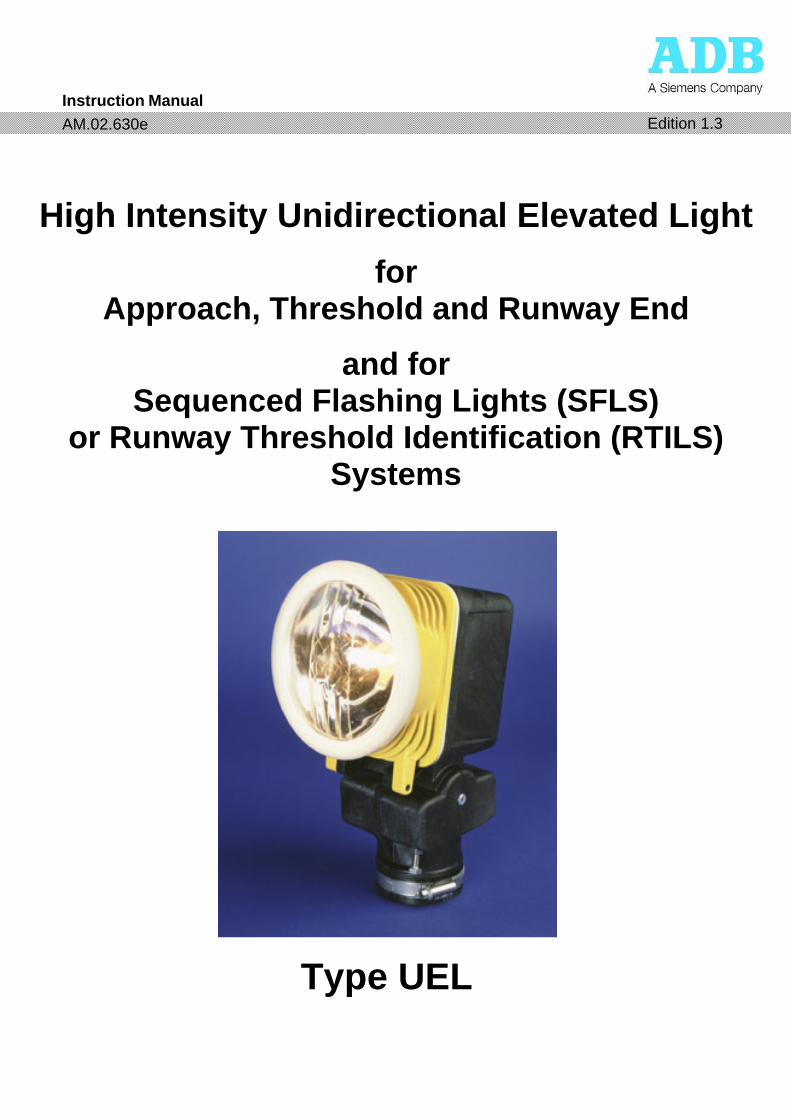
High Intensity Unidirectional Elevated Light
for Approach, Threshold and Runway End
and for Sequenced Flashing Lights (SFLS)
or Runway Threshold Identification (RTILS) Systems
Type UEL
Instruction Manual AM.02.630e Edition 1.3
AM.02.630e edition 1
1
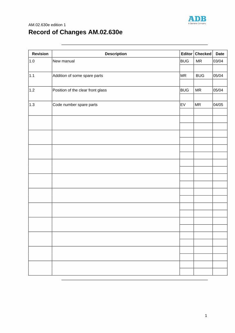
Record of Changes AM.02.630e
Revision Description Editor Checked Date
1.0 New manual BUG MR 03/04
1.1 Addition of some spare parts MR BUG 05/04
1.2 Position of the clear front glass BUG MR 05/04
1.3 Code number spare parts EV MR 04/05
AM.02.630e edition 1
2
Safety Instructions
Operating and maintenance personnel should refer to ICAO Airport Services Manual Part 9, “Airport Maintenance Practices” and to FAA Advisory Circular AC 150/5340-26 "Maintenance of Airport Visual Aid Facilities" for instructions on safety precautions. Personnel must always observe the safety regulations. The equipment has been designed and manufactured to allow safe and secure operation, however, the following rules must be strictly observed.
Operating and maintenance personnel must always observe all safety regulations.
Do not change lamps or components or make adjustments to equipment when the light circuit is switched on.
See FAA Advisory Circular AC 150/5340-26 concerning safety.
Operating and maintenance personnel should get acquainted with the resuscitation techniques described in the First Aid Instruction Manual as issued by the Red Cross Organisation or similar.
Safety precautions
Keep away from live circuits
Resuscitation
AM.02.630e edition 1
3
Use Restriction Notice and Warranty
The content of this Instruction Manual is the property of
n.v. ADB s.a.
585, Leuvensesteenweg
B-1930 Zaventem - Belgium
Tel. 32 2 722 17 11 Fax 32 2 722 17 64
E-mail: [email protected]
Internet: http://www.adb-air.com
This manual or parts thereof may not be reproduced, stored in a retrieval system or transmitted, in any form or by any means, electronic, mechanical, photocopying, recording or otherwise, without ADB's prior written consent.
N.V. ADB S.A. guarantees that the performance of the products described in this manual, when sold by ADB or its licensed representatives, meets the requirements of ICAO Annex 14, Volume 1, and FAA specification AC 150/5345-46.
Any defect in design, material or workmanship, which may occur during proper and normal use over a period of one (1) year from date of shipment, will be repaired or replaced by ADB free of charge, ex works. Operational failure resulting from lamp burnt out, improper maintenance or installation, damage due to runway maintenance equipment, snow ploughs or aircraft arresting gear hooks is not considered a result of proper use and is beyond the scope of the warranty.
Warranty does not cover natural wear and tear nor damage arising after delivery owing to faulty or negligent handling, excessive strain, unsuitable materials for operation, deficient civil engineering work, unsuitable soil conditions, and such chemical, electrochemical or electrical influences as were not assumed at the time of the contract.
All liability for consequences of any inexpert alterations or repairs carried out by Purchaser or a third party shall be waived.
N.V. ADB S.A. shall in no event be liable to Purchaser for any further claims, particularly claims for damages not affecting the goods themselves.
The above constitutes the limits of ADB’s liabilities in connection with the products covered by this manual.
Use restriction notice
Warranty
AM.02.630e edition 1
4
Information about this Manual
Each chapter starts with an overview of the topics treated in that chapter.
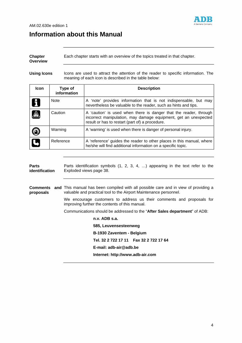
Icons are used to attract the attention of the reader to specific information. The meaning of each icon is described in the table below:
Icon Type of information
Description
Note A ‘note’ provides information that is not indispensable, but may
nevertheless be valuable to the reader, such as hints and tips.
Caution A ‘caution’ is used when there is danger that the reader, through
incorrect manipulation, may damage equipment, get an unexpected result or has to restart (part of) a procedure.
Warning A ‘warning’ is used when there is danger of personal injury.
Reference A ‘reference’ guides the reader to other places in this manual, where
he/she will find additional information on a specific topic.
Parts identification symbols (1, 2, 3, 4, …) appearing in the text refer to the Exploded views page 38.
This manual has been compiled with all possible care and in view of providing a valuable and practical tool to the Airport Maintenance personnel.
We encourage customers to address us their comments and proposals for improving further the contents of this manual.
Communications should be addressed to the “After Sales department” of ADB:
n.v. ADB s.a.
585, Leuvensesteenweg
B-1930 Zaventem - Belgium
Tel. 32 2 722 17 11 Fax 32 2 722 17 64
E-mail: [email protected]
Internet: http://www.adb-air.com
Chapter Overview
Using Icons
Parts identification
Comments and proposals
AM.02.630e edition 1
5
Table of Contents
Safety Instructions 2
Use Restriction Notice and Warranty 3
Information about this Manual 4
Chapter 1: General Information and Requirements 6 General information 7 Product data 8
Chapter 2: Installation 10 General recommendations 11 Equipment required for installation 12 How to mount the UEL at ground level 13 How to mount the UEL on a 60mm O.D. conduit 16 How to mount the UEL on a safety approach mast 20
Chapter 3: Orientation and elevation settings 22 Standard levelling device 23 Electronic levelling device 25 Commissioning 27
Chapter 4: Maintenance 28 Preventive maintenance 29 How to replace the lamp 30 How to dismantle the optical assembly 32
Chapter 5: Troubleshooting 33
Chapter 6: Assemblies and Exploded Views 34 Assemblies 35 Exploded views 38
AM.02.630e edition 1
Chapter 1: General Information and Requirements 6
Chapter 1: General Information and Requirements
Overview
In this chapter you will find general information about the UEL lights.
This chapter contains the following topics.
Topic See Page
General information 7
Product data 8
Introduction
Contents
AM.02.630e edition 1
Chapter 1: General Information and Requirements 7
General information
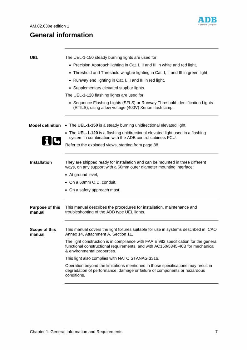
The UEL-1-150 steady burning lights are used for:
• Precision Approach lighting in Cat. I, II and III in white and red light,
• Threshold and Threshold wingbar lighting in Cat. I, II and III in green light,
• Runway end lighting in Cat. I, II and III in red light,
• Supplementary elevated stopbar lights.
The UEL-1-120 flashing lights are used for:
• Sequence Flashing Lights (SFLS) or Runway Threshold Identification Lights (RTILS), using a low voltage (400V) Xenon flash lamp.
• The UEL-1-150 is a steady burning unidirectional elevated light.
• The UEL-1-120 is a flashing unidirectional elevated light used in a flashing system in combination with the ADB control cabinets FCU.
Refer to the exploded views, starting from page 38.
They are shipped ready for installation and can be mounted in three different ways, on any support with a 60mm outer diameter mounting interface:
• At ground level,
• On a 60mm O.D. conduit,
• On a safety approach mast.
This manual describes the procedures for installation, maintenance and troubleshooting of the ADB type UEL lights.
This manual covers the light fixtures suitable for use in systems described in ICAO Annex 14, Attachment A, Section 11.
The light construction is in compliance with FAA E 982 specification for the general functional constructional requirements, and with AC150/5345-46B for mechanical & environmental properties.
This light also complies with NATO STANAG 3316.
Operation beyond the limitations mentioned in those specifications may result in degradation of performance, damage or failure of components or hazardous conditions.
UEL
Model definition
Installation
Purpose of this manual
Scope of this manual
AM.02.630e edition 1
Chapter 1: General Information and Requirements 8
Product data
UEL units are either packed individually in a durable, cushioned and corrugated cardboard box, labelled with ADB and ordering numbers, or on pallet boxes in larger quantities.
Depending on the ordered code number, the fittings are supplied:
• with lamp (packed separately),
• with or without power supply cable cable (packed separately),
• with or without top light (see page 38).
Unless contractually specified differently, one instruction manual is delivered per order.
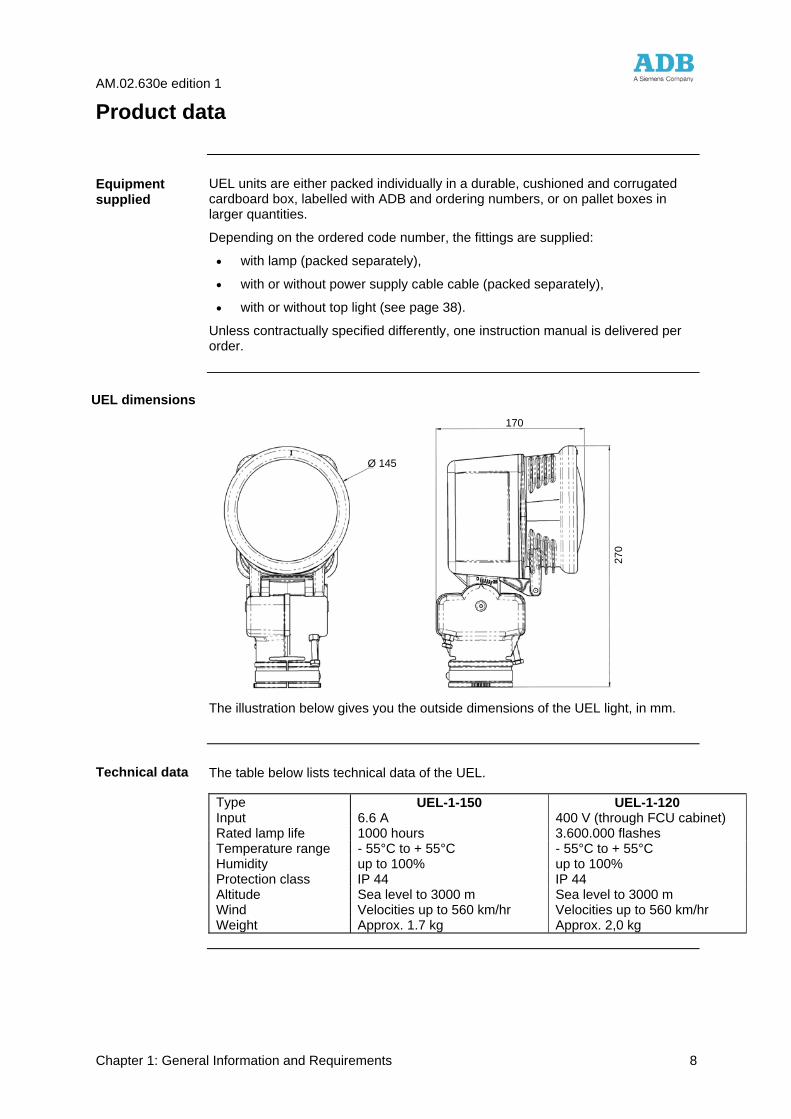
The illustration below gives you the outside dimensions of the UEL light, in mm.
The table below lists technical data of the UEL.
Type UEL-1-150 UEL-1-120 Input 6.6 A 400 V (through FCU cabinet) Rated lamp life 1000 hours 3.600.000 flashes Temperature range - 55°C to + 55°C - 55°C to + 55°C Humidity up to 100% up to 100% Protection class IP 44 IP 44 Altitude Sea level to 3000 m Sea level to 3000 m Wind Velocities up to 560 km/hr Velocities up to 560 km/hr Weight Approx. 1.7 kg Approx. 2,0 kg
Equipment supplied
UEL dimensions
Technical data
Ø 145
270
170
AM.02.630e edition 1
Chapter 1: General Information and Requirements 9
Ordering codes and reference data pertinent to the product are listed in the tables on page 36.
References
AM.02.630e edition 1
Chapter 2: Installation 10
Chapter 2: Installation
Overview
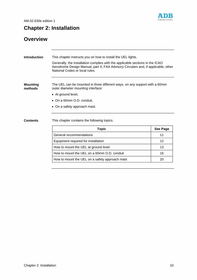
This chapter instructs you on how to install the UEL lights.
Generally, the installation complies with the applicable sections in the ICAO Aerodrome Design Manual, part 4, FAA Advisory Circulars and, if applicable, other National Codes or local rules.
The UEL can be mounted in three different ways, on any support with a 60mm outer diameter mounting interface:
• At ground level,
• On a 60mm O.D. conduit,
• On a safety approach mast.
This chapter contains the following topics.
Topic See Page
General recommendations 11
Equipment required for installation 12
How to mount the UEL at ground level 13
How to mount the UEL on a 60mm O.D. conduit 16
How to mount the UEL on a safety approach mast 20
Introduction
Mounting methods
Contents
AM.02.630e edition 1
Chapter 2: Installation 11
General recommendations
1. Upon receipt of goods at the site store, check all packings for visible damage.
Every damaged box should be opened and its content inspected for damage.
If equipment is damaged, a claim form shall be filed with the carrier immediately. It may then be necessary for the carrier to inspect the equipment.
2. Store the light assembly preferably in its original packing in a protected area. When stored unpacked, please take care not to damage the cable insulation.
3. Unpack the light assembly at the installation site to avoid damage during transportation and handling.
The UEL-1-150 light assemblies are designed for connection to 6.6 or 20
Amps series circuits via one FAA L-830 or L-831 isolation transformer (type ADB : RST), with a nominal secondary current of 6,6A. Refer to ADB cat. leaflet A.06.110 or Instruction manual AM.06.110 for more information on isolation transformers. The isolation transformers are to be ordered separately.
The UEL-1-120 light assemblies are designed for connection to a FCU control cabinet by means of a 5-core cable. Refer to ADB Instruction Manual A.02.6200 for more information on the connection to the FCU control cabinet and the type of cable to use. The FCU control cabinets are to be ordered separately.
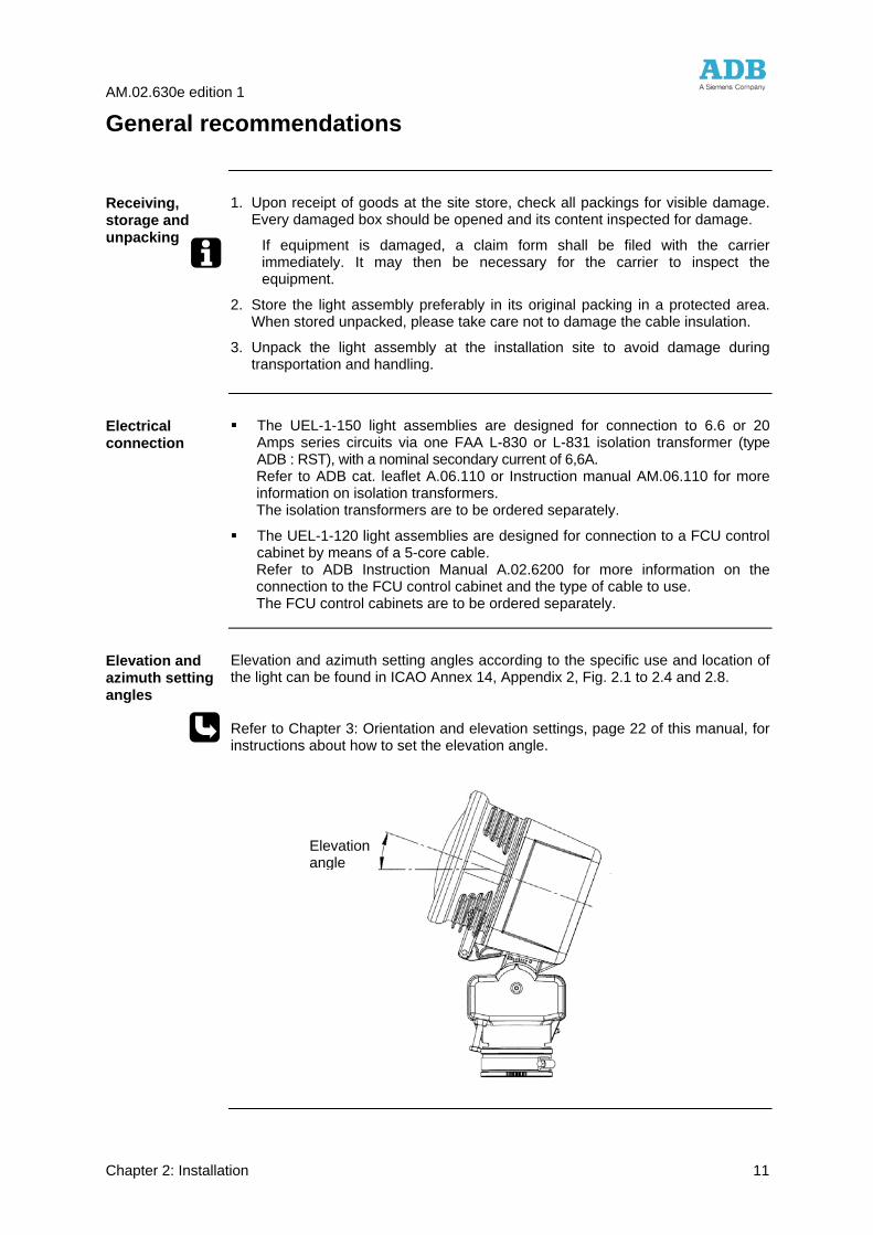
Elevation and azimuth setting angles according to the specific use and location of the light can be found in ICAO Annex 14, Appendix 2, Fig. 2.1 to 2.4 and 2.8.
Refer to Chapter 3: Orientation and elevation settings, page 22 of this manual, for instructions about how to set the elevation angle.
Receiving, storage and unpacking
Electrical connection
Elevation and azimuth setting angles
Elevation angle
AM.02.630e edition 1
Chapter 2: Installation 12
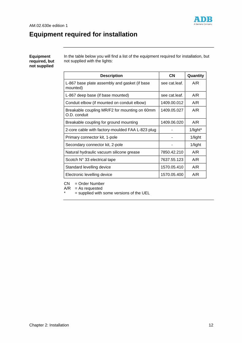
Equipment required for installation
In the table below you will find a list of the equipment required for installation, but not supplied with the lights:
Description CN Quantity
L-867 base plate assembly and gasket (if base mounted)
see cat.leaf. A/R
L-867 deep base (if base mounted) see cat.leaf. A/R
Conduit elbow (if mounted on conduit elbow) 1409.00.012 A/R
Breakable coupling MR/F2 for mounting on 60mm O.D. conduit
1409.05.027 A/R
Breakable coupling for ground mounting 1409.06.020 A/R
2-core cable with factory-moulded FAA L-823 plug - 1/light*
Primary connector kit, 1-pole - 1/light
Secondary connector kit, 2-pole - 1/light
Natural hydraulic vacuum silicone grease 7850.42.210 A/R
Scotch N° 33 electrical tape 7637.55.123 A/R
Standard levelling device 1570.05.410 A/R
Electronic levelling device 1570.05.400 A/R
CN = Order Number A/R = As requested * = supplied with some versions of the UEL
Equipment required, but not supplied
AM.02.630e edition 1
Chapter 2: Installation 13
How to mount the UEL at ground level
The UEL is mounted on a breakable coupling which is screwed into a mounting device such as a conduit elbow or a deep base with cover.
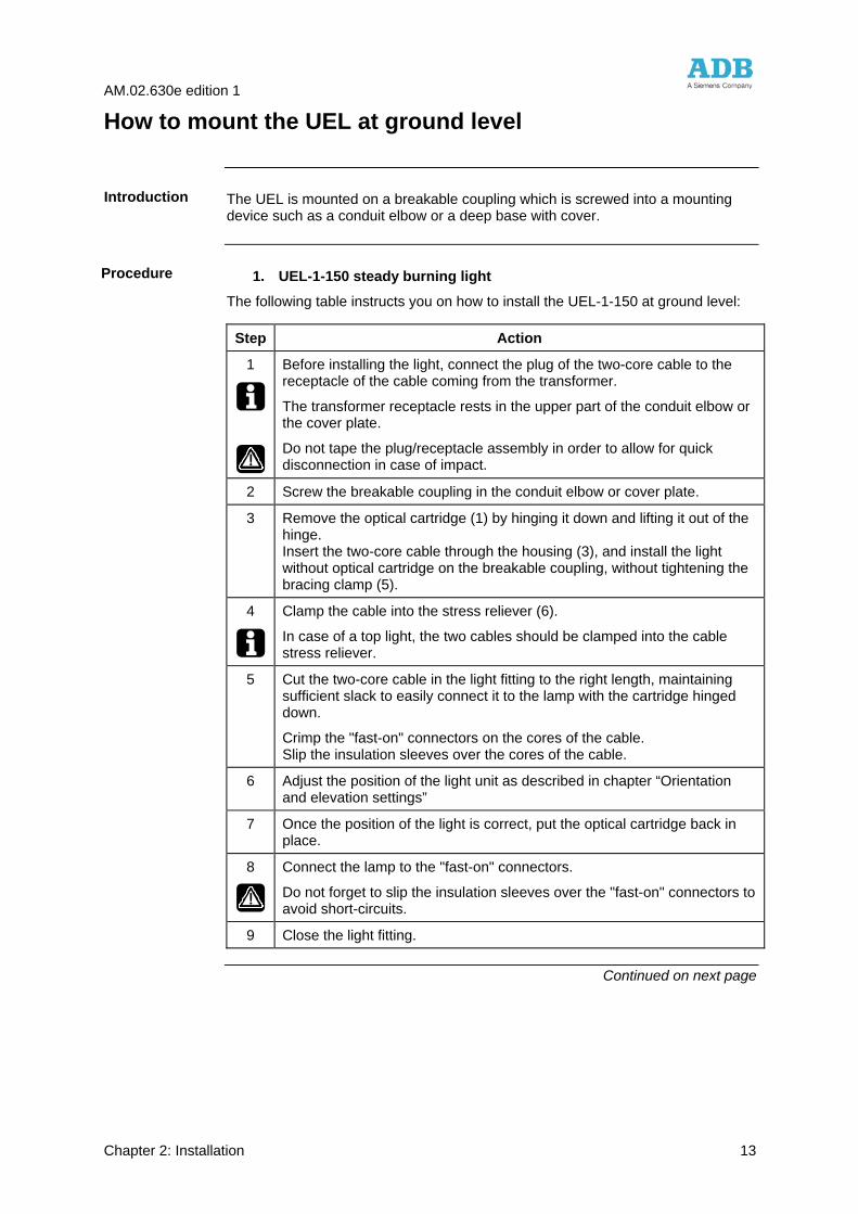
1. UEL-1-150 steady burning light
The following table instructs you on how to install the UEL-1-150 at ground level:
Step Action
1
Before installing the light, connect the plug of the two-core cable to the receptacle of the cable coming from the transformer.
The transformer receptacle rests in the upper part of the conduit elbow or the cover plate.
Do not tape the plug/receptacle assembly in order to allow for quick disconnection in case of impact.
2 Screw the breakable coupling in the conduit elbow or cover plate.
3 Remove the optical cartridge (1) by hinging it down and lifting it out of the hinge. Insert the two-core cable through the housing (3), and install the light without optical cartridge on the breakable coupling, without tightening the bracing clamp (5).
4
Clamp the cable into the stress reliever (6).
In case of a top light, the two cables should be clamped into the cable stress reliever.
5 Cut the two-core cable in the light fitting to the right length, maintaining sufficient slack to easily connect it to the lamp with the cartridge hinged down.
Crimp the "fast-on" connectors on the cores of the cable. Slip the insulation sleeves over the cores of the cable.
6 Adjust the position of the light unit as described in chapter “Orientation and elevation settings”
7 Once the position of the light is correct, put the optical cartridge back in place.
8
Connect the lamp to the "fast-on" connectors.
Do not forget to slip the insulation sleeves over the "fast-on" connectors to avoid short-circuits.
9 Close the light fitting.
Continued on next page
Introduction
Procedure
AM.02.630e edition 1
Chapter 2: Installation 14
How to mount the UEL at ground level, continued
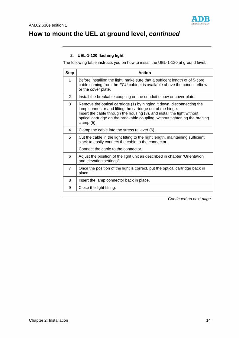
2. UEL-1-120 flashing light
The following table instructs you on how to install the UEL-1-120 at ground level:
Step Action
1 Before installing the light, make sure that a sufficent length of of 5-core cable coming from the FCU cabinet is available above the conduit elbow or the cover plate.
2 Install the breakable coupling on the conduit elbow or cover plate.
3 Remove the optical cartridge (1) by hinging it down, disconnecting the lamp connector and lifting the cartridge out of the hinge. Insert the cable through the housing (3), and install the light without optical cartridge on the breakable coupling, without tightening the bracing clamp (5).
4 Clamp the cable into the stress reliever (6).
5 Cut the cable in the light fitting to the right length, maintaining sufficient slack to easily connect the cable to the connector.
Connect the cable to the connector.
6 Adjust the position of the light unit as described in chapter “Orientation and elevation settings”.
7 Once the position of the light is correct, put the optical cartridge back in place.
8 Insert the lamp connector back in place.
9 Close the light fitting.
Continued on next page
AM.02.630e edition 1
Chapter 2: Installation 15
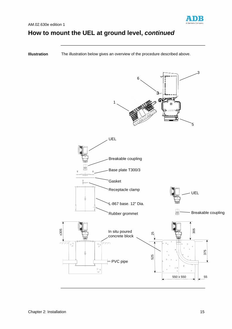
How to mount the UEL at ground level, continued
The illustration below gives an overview of the procedure described above.
Illustration
550 x 550 55
±305
305
375
525
25
UEL
Breakable coupling
Base plate T300/3
Gasket
Receptacle clamp
L-867 base, 12” Dia.
Rubber grommet
In situ poured concrete block
PVC pipe
Breakable coupling
UEL
1
6
5
3
AM.02.630e edition 1
Chapter 2: Installation 16
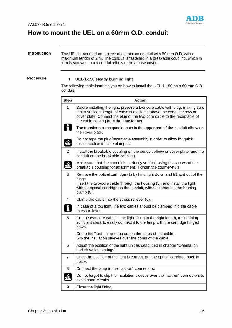
How to mount the UEL on a 60mm O.D. conduit
The UEL is mounted on a piece of aluminium conduit with 60 mm O.D, with a maximum length of 2 m. The conduit is fastened in a breakable coupling, which in turn is screwed into a conduit elbow or on a base cover.
1. UEL-1-150 steady burning light
The following table instructs you on how to install the UEL-1-150 on a 60 mm O.D. conduit:
Step Action
1
Before installing the light, prepare a two-core cable with plug, making sure that a sufficent length of cable is available above the conduit elbow or cover plate. Connect the plug of the two-core cable to the receptacle of the cable coming from the transformer.
The transformer receptacle rests in the upper part of the conduit elbow or the cover plate.
Do not tape the plug/receptacle assembly in order to allow for quick disconnection in case of impact.
2
Install the breakable coupling on the conduit elbow or cover plate, and the conduit on the breakable coupling.
Make sure that the conduit is perfectly vertical, using the screws of the breakable coupling for adjustment. Tighten the counter-nuts.
3 Remove the optical cartridge (1) by hinging it down and lifting it out of the hinge. Insert the two-core cable through the housing (3), and install the light without optical cartridge on the conduit, without tightening the bracing clamp (5).
4
Clamp the cable into the stress reliever (6).
In case of a top light, the two cables should be clamped into the cable stress reliever.
5 Cut the two-core cable in the light fitting to the right length, maintaining sufficient slack to easily connect it to the lamp with the cartridge hinged down.
Crimp the "fast-on" connectors on the cores of the cable. Slip the insulation sleeves over the cores of the cable.
6 Adjust the position of the light unit as described in chapter “Orientation and elevation settings”
7 Once the position of the light is correct, put the optical cartridge back in place.
8
Connect the lamp to the "fast-on" connectors.
Do not forget to slip the insulation sleeves over the "fast-on" connectors to avoid short-circuits.
9 Close the light fitting.
Introduction
Procedure
AM.02.630e edition 1
Chapter 2: Installation 17
Continued on next page
AM.02.630e edition 1
Chapter 2: Installation 18
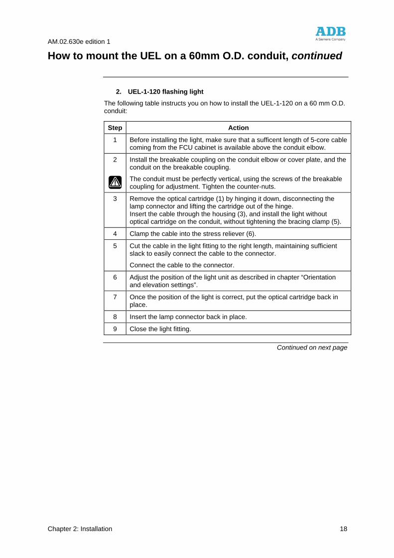
How to mount the UEL on a 60mm O.D. conduit, continued
2. UEL-1-120 flashing light
The following table instructs you on how to install the UEL-1-120 on a 60 mm O.D. conduit:
Step Action
1 Before installing the light, make sure that a sufficent length of 5-core cable coming from the FCU cabinet is available above the conduit elbow.
2
Install the breakable coupling on the conduit elbow or cover plate, and the conduit on the breakable coupling.
The conduit must be perfectly vertical, using the screws of the breakable coupling for adjustment. Tighten the counter-nuts.
3 Remove the optical cartridge (1) by hinging it down, disconnecting the lamp connector and lifting the cartridge out of the hinge. Insert the cable through the housing (3), and install the light without optical cartridge on the conduit, without tightening the bracing clamp (5).
4 Clamp the cable into the stress reliever (6).
5 Cut the cable in the light fitting to the right length, maintaining sufficient slack to easily connect the cable to the connector.
Connect the cable to the connector.
6 Adjust the position of the light unit as described in chapter “Orientation and elevation settings”.
7 Once the position of the light is correct, put the optical cartridge back in place.
8 Insert the lamp connector back in place.
9 Close the light fitting.
Continued on next page
AM.02.630e edition 1
Chapter 2: Installation 19
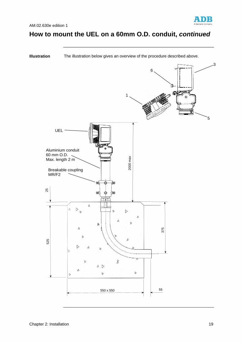
How to mount the UEL on a 60mm O.D. conduit, continued
The illustration below gives an overview of the procedure described above.
Illustration
UEL
Aluminium conduit 60 mm O.D. Max. length 2 m
Breakable coupling MR/F2
550 x 550 55
2000
max
375
525
25
1
6
5
3
AM.02.630e edition 1
Chapter 2: Installation 20
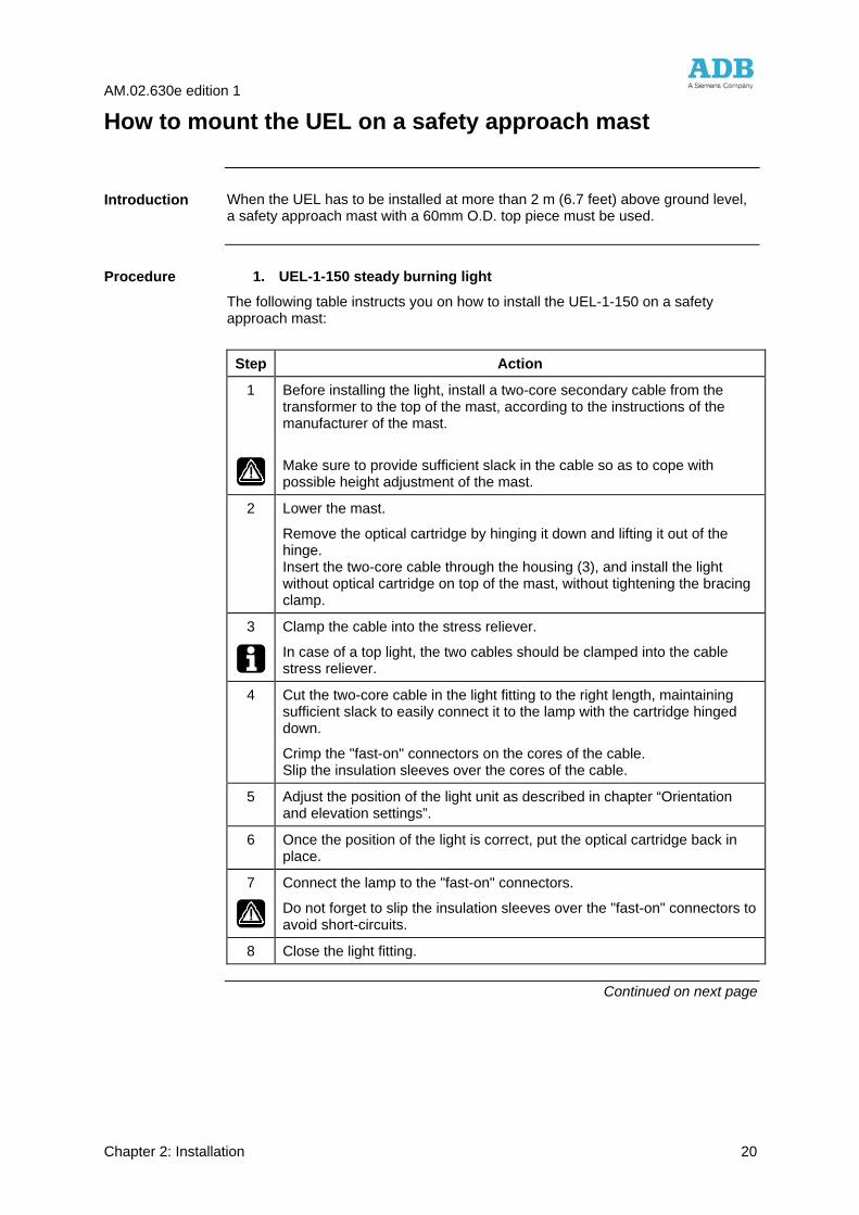
How to mount the UEL on a safety approach mast
When the UEL has to be installed at more than 2 m (6.7 feet) above ground level, a safety approach mast with a 60mm O.D. top piece must be used.
1. UEL-1-150 steady burning light
The following table instructs you on how to install the UEL-1-150 on a safety approach mast:
Step Action
1
Before installing the light, install a two-core secondary cable from the transformer to the top of the mast, according to the instructions of the manufacturer of the mast.
Make sure to provide sufficient slack in the cable so as to cope with possible height adjustment of the mast.
2 Lower the mast.
Remove the optical cartridge by hinging it down and lifting it out of the hinge. Insert the two-core cable through the housing (3), and install the light without optical cartridge on top of the mast, without tightening the bracing clamp.
3
Clamp the cable into the stress reliever.
In case of a top light, the two cables should be clamped into the cable stress reliever.
4 Cut the two-core cable in the light fitting to the right length, maintaining sufficient slack to easily connect it to the lamp with the cartridge hinged down.
Crimp the "fast-on" connectors on the cores of the cable. Slip the insulation sleeves over the cores of the cable.
5 Adjust the position of the light unit as described in chapter “Orientation and elevation settings”.
6 Once the position of the light is correct, put the optical cartridge back in place.
7
Connect the lamp to the "fast-on" connectors.
Do not forget to slip the insulation sleeves over the "fast-on" connectors to avoid short-circuits.
8 Close the light fitting.
Continued on next page
Introduction
Procedure
AM.02.630e edition 1
Chapter 2: Installation 21
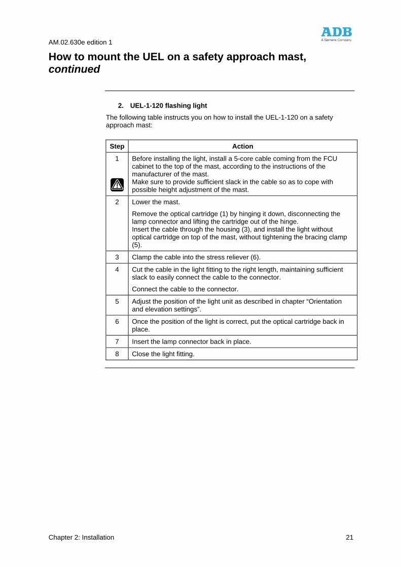
How to mount the UEL on a safety approach mast, continued
2. UEL-1-120 flashing light
The following table instructs you on how to install the UEL-1-120 on a safety approach mast:
Step Action
1
Before installing the light, install a 5-core cable coming from the FCU cabinet to the top of the mast, according to the instructions of the manufacturer of the mast. Make sure to provide sufficient slack in the cable so as to cope with possible height adjustment of the mast.
2 Lower the mast.
Remove the optical cartridge (1) by hinging it down, disconnecting the lamp connector and lifting the cartridge out of the hinge. Insert the cable through the housing (3), and install the light without optical cartridge on top of the mast, without tightening the bracing clamp (5).
3 Clamp the cable into the stress reliever (6).
4 Cut the cable in the light fitting to the right length, maintaining sufficient slack to easily connect the cable to the connector.
Connect the cable to the connector.
5 Adjust the position of the light unit as described in chapter “Orientation and elevation settings”.
6 Once the position of the light is correct, put the optical cartridge back in place.
7 Insert the lamp connector back in place.
8 Close the light fitting.
AM.02.630e edition 1
Chapter 3: Orientation and elevation settings 22
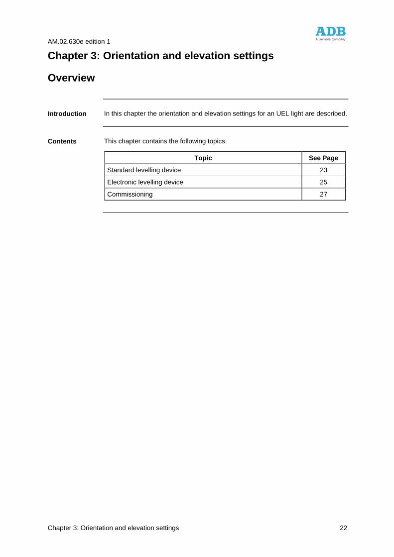
Chapter 3: Orientation and elevation settings
Overview
In this chapter the orientation and elevation settings for an UEL light are described.
This chapter contains the following topics.
Topic See Page
Standard levelling device 23
Electronic levelling device 25
Commissioning 27
Introduction
Contents
AM.02.630e edition 1
Chapter 3: Orientation and elevation settings 23
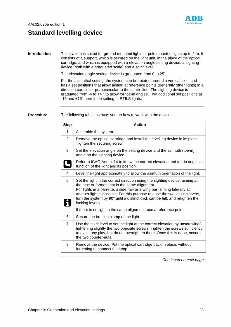
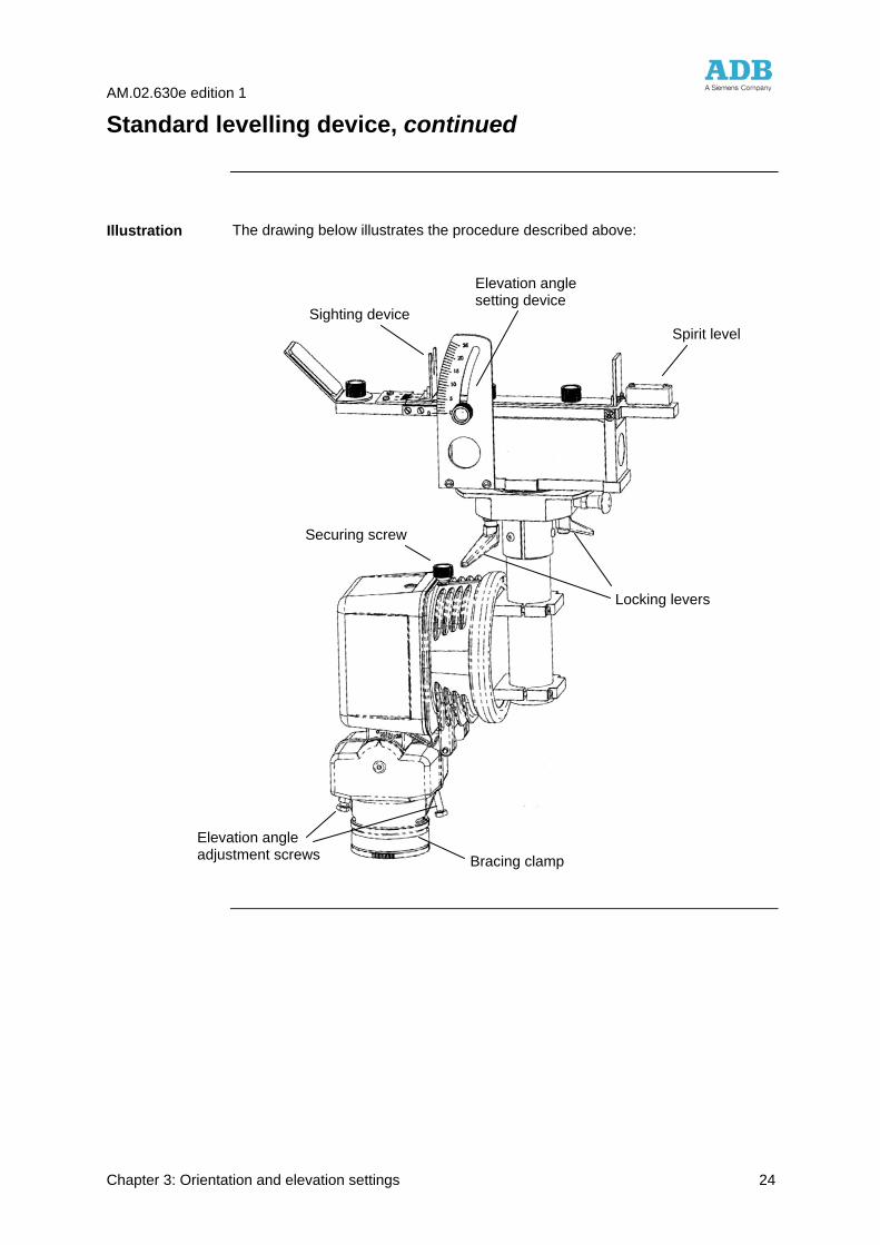
Standard levelling device
This system is suited for ground mounted lights or pole mounted lights up to 2 m. It consists of a support, which is secured on the light unit, in the place of the optical cartridge, and which is equipped with a elevation angle setting device, a sighting device (both with a graduated scale) and a spirit level.
The elevation angle setting device is graduated from 0 to 25°.
For the azimuthal setting, the system can be rotated around a vertical axis, and has 4 set positions that allow aiming at reference points (generally other lights) in a direction parallel or perpendicular to the centre line. The sighting device is graduated from -4 to +4 ° to allow for toe-in angles. Two additional set positions at -15 and +15° permit the setting of RTILS lights.
The following table instructs you on how to work with the device:
Step Action
1 Assemble the system.
2 Remove the optical cartridge and install the levelling device in its place. Tighten the securing screw.
3
Set the elevation angle on the setting device and the azimuth (toe-in) angle on the sighting device.
Refer to ICAO Annex 14 to know the correct elevation and toe-in angles in function of the light and its position.
4 Level the light approximately to allow the azimuth orientation of the light.
5
Set the light in the correct direction using the sighting device, aiming at the next or former light in the same alignment. For lights in a barrette, a side row or a wing bar, aiming laterally at another light is possible. For this purpose release the two locking levers, turn the system by 90° until a distinct click can be felt, and retighten the locking levers.
If there is no light in the same alignment, use a reference pole.
6 Secure the bracing clamp of the light.
7 Use the spirit level to set the light at the correct elevation by unscrewing/ tightening slightly the two opposite screws. Tighten the screws sufficiently to avoid any play, but do not overtighten them. Once this is done, secure the two counter-nuts.
8 Remove the device. Put the optical cartridge back in place, without forgetting to connect the lamp.
Continued on next page
Introduction
Procedure
AM.02.630e edition 1
Chapter 3: Orientation and elevation settings 24
Standard levelling device, continued
The drawing below illustrates the procedure described above:
Illustration
Securing screw
Elevation angle setting device
Sighting device Spirit level
Locking levers
Elevation angle adjustment screws Bracing clamp
AM.02.630e edition 1
Chapter 3: Orientation and elevation settings 25
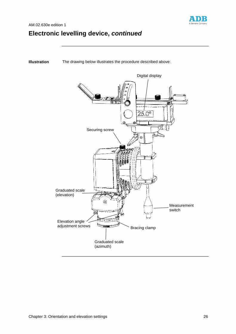
Electronic levelling device
This system is suited for fittings mounted on safety approach masts, when it is not possible to get access to the top of the mast in its standing position.
The system consists of a support similar to the one used with the standard simplified levelling device (see page 23). However, the support is equipped with a sensor activated with a switch, with a 10 m long cable. The operator can then operate the sensor from the ground, and read the elevation angle measurement when the mast is tilted to the ground.
The following table instructs you on how to work with the device:
Step Action
1
Lower the mast.
See instruction manual of the supplied masts.
2 If the mast has been correctly installed, i.e. its tilting axis is perpendicular to the centre line, a light with 0° toe-in will have its front surface fully horizontal when the mast is tilted over 90° (down to the horizontal). With the mast in this position, adjust the light by turning it around the tube, and then tighten the bracing clamp.
For lights with a toe-in, first adjust the light for 0° toe-in. Make a reference mark on the tube just below the zero mark at the bottom of the slip fitter. Using the graduated scale, turn the light around the tube to the desired toe-in, and tighten the bracing clamp.
3 Remove the optical cartridge and install the levelling device in its place. Tighten the securing screw.
4 Raise the mast. Operate the switch to take a measurement.
5 Lower the mast and read the angle indicated on the digital display. Calculate the difference between the real angle and the required one.
6
If necessary, adjust the elevation angle by unscrewing/tightening slightly the two opposite screws. Tighten the screws sufficiently to avoid any play, but do not overtighten them. Once this is done, secure the two counter-nuts. While doing the correction, two measurements means are useable: - The elevation scale on the side of the light body (coarse measurement); - The levelling device itself, by taking a measurement before and after correction (fine measurement).
7 Raise the mast and repeat the operation 6 until the adjustment is correct.
8 Lower the mast and remove the device. Put the optical cartridge back in place, without forgetting to connect the lamp.
Note:
During the installation of the approach line, a quicker method is to use a platform at the light level for an easy initial adjustment.
Continued on next page
Introduction
Composition
Procedure
AM.02.630e edition 1
Chapter 3: Orientation and elevation settings 26
Electronic levelling device, continued
The drawing below illustrates the procedure described above:
Illustration
Securing screw
Digital display
Graduated scale (azimuth)
Measurement switch
Elevation angle adjustment screws Bracing clamp
Graduated scale (elevation)
AM.02.630e edition 1
Chapter 3: Orientation and elevation settings 27
Commissioning
A flight check shall be performed to detect gross misalignment in the approach and runway threshold lighting system.
Errors shall be corrected and the system shall not be put in operation until it has been found satisfactory during the flight test.
Final check
AM.02.630e edition 1
Chapter 4: Maintenance 28
Chapter 4: Maintenance
Overview
In this chapter, maintenance of the UEL light is described as well as the procedures of how to replace the lamp and the optical cartridge.
Preventive maintenance of the light fixtures should be performed as listed in the table on the next page.
Maintenance frequency depends on the conditions under which the runway is used (i.e. climate, traffic, etc.). The recommended practices for maintenance are described in the FAA Advisory Circular no. AC 150/5340-26.
For the numbering of the components mentioned in this chapter, refer to the exploded view on page 38.
This chapter contains the following topics.
Topic See Page
Preventive maintenance 29
How to replace the lamp 30
How to dismantle the optical assembly 32
Introduction
Contents
AM.02.630e edition 1
Chapter 4: Maintenance 29
Preventive maintenance
In the table below you will find a checklist of preventive maintenance tasks.
Before attempting to service, de-energize and lockout the circuit or the regulator so that the fixture can not be energized by remote means.
Interval Check Action
Daily Lamp failure Replace lamp.
Dimly burning lamp Replace lamp if discoloured, blackened or distorted.
Broken lens Replace optical cartridge.
Weekly Obtrusion of the light beam by vegetation
1. Remove vegetation.
2. Use weed killer.
Dirty lens Clean with glass cleaner.
Monthly Fixture misalignment Straighten level and align fixture.
Semi-annually * Presence of water in optical cartridge
Inspection of the light: check drain holes and status of the lens and gaskets.
Paint flaking off Paint anew.
Annually Cracks, corrosion, shorts Repair or replace.
Dirty contacts Clean when system is deactivated.
Loose connections Tighten loose connections.
In prediction of heavy snowfall
Mark location of low mounted fixtures (use red flags or sticks) to facilitate snow removal and lessen the risk of damage to the fixtures by snow removal equipment.
* More frequently during rainy seasons.
Preventive maintenance tasks
AM.02.630e edition 1
Chapter 4: Maintenance 30
How to replace the lamp
Lamp replacement can be performed preferably in the maintenance base, or on site, at the location of installation. The following table instructs you on how to replace a lamp in the maintenance base:
Step Action
1 Open the fitting by hinging down the optical cartridge (1).
2 (UEL-1-150): Slide the insulating sleeves away from the "fast-on" connectors and disconnect the lamp (2) from the cable wires.
(UEL-1-120): Disconnect the cable from the lamp (2).
3 Remove the optical cartridge and replace it by another one of the same model, in overhauled condition. If damaged, replace the insulation sleeves.
4 (UEL-1-150): Reconnect the lamp. Apply a light coat of silicone grease on the fast-on connectors. Slide the insulating sleeves back in place over the fast - on connectors
(UEL-1-150): Re-connect the lamp cable
5 Close the optical cartridge.
6 Back in the maintenance base:
1- Remove the lamp (on the UEL-1-120, by unscrewing the four fixation screws) 2- Clean the cartridge and especially the front glass (1b), check the condition of the reflector (1c), the gaskets (1a and 1d) and the spring (7), and replace if needed. 3- Carefully install the new lamp in the keyed aperture at the rear of the optical cartridge (on the UEL-1-120, retighten the four screws).
The optical cartridge is now ready to be used again.
1. In case of relamping executed in the field, the lamp can be changed without removing the optical cartridge from the light. The quality of the result can be affected, most of all in case of night work, rain or cold conditions.
2. Touching the quartz bulb with bare fingers may seriously shorten the lamp’s life. If the bulb has been touched, wipe it carefully with a piece of lens cleaning tissue or similar material moistened with alcohol.
Continued on next page
Procedure
AM.02.630e edition 1
Chapter 4: Maintenance 31
How to replace the lamp, continued
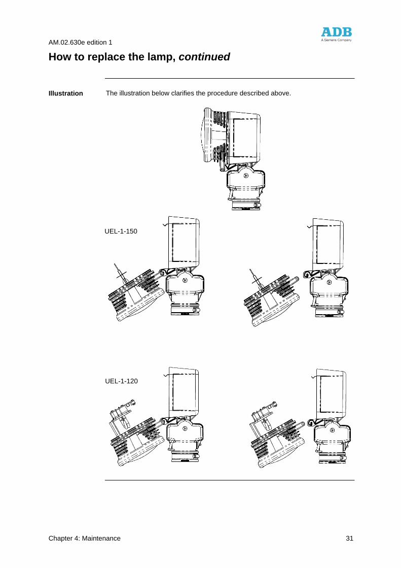
The illustration below clarifies the procedure described above.
Illustration
UEL-1-150
UEL-1-120
AM.02.630e edition 1
Chapter 4: Maintenance 32
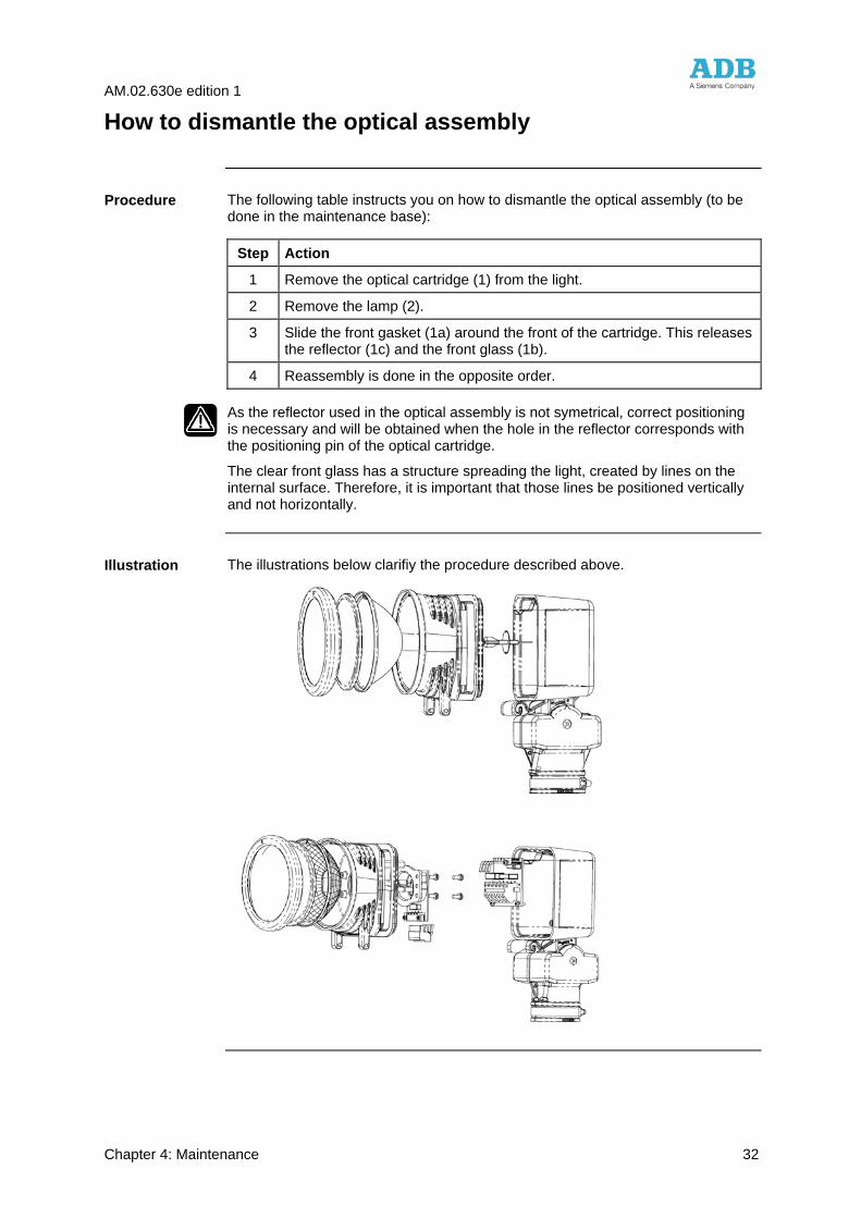
How to dismantle the optical assembly
The following table instructs you on how to dismantle the optical assembly (to be done in the maintenance base):
Step Action
1 Remove the optical cartridge (1) from the light.
2 Remove the lamp (2).
3 Slide the front gasket (1a) around the front of the cartridge. This releases the reflector (1c) and the front glass (1b).
4 Reassembly is done in the opposite order.
As the reflector used in the optical assembly is not symetrical, correct positioning is necessary and will be obtained when the hole in the reflector corresponds with the positioning pin of the optical cartridge.
The clear front glass has a structure spreading the light, created by lines on the internal surface. Therefore, it is important that those lines be positioned vertically and not horizontally.
The illustrations below clarifiy the procedure described above.
Procedure
Illustration
AM.02.630e edition 1
Chapter 5: Troubleshooting 33
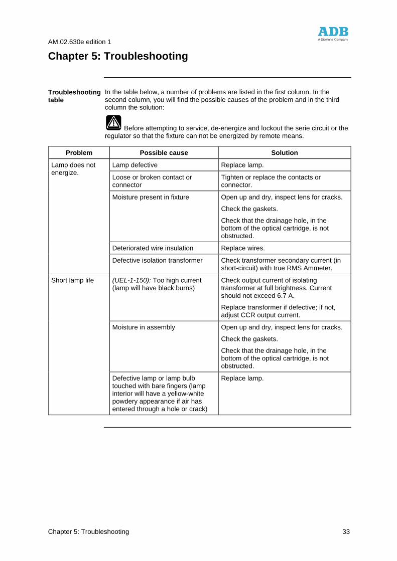
Chapter 5: Troubleshooting
In the table below, a number of problems are listed in the first column. In the second column, you will find the possible causes of the problem and in the third column the solution:
Before attempting to service, de-energize and lockout the serie circuit or the regulator so that the fixture can not be energized by remote means.
Problem Possible cause Solution
Lamp defective Replace lamp. Lamp does not energize.
Loose or broken contact or connector
Tighten or replace the contacts or connector.
Moisture present in fixture Open up and dry, inspect lens for cracks.
Check the gaskets.
Check that the drainage hole, in the bottom of the optical cartridge, is not obstructed.
Deteriorated wire insulation Replace wires.
Defective isolation transformer Check transformer secondary current (in short-circuit) with true RMS Ammeter.
Short lamp life (UEL-1-150): Too high current (lamp will have black burns)
Check output current of isolating transformer at full brightness. Current should not exceed 6.7 A.
Replace transformer if defective; if not, adjust CCR output current.
Moisture in assembly Open up and dry, inspect lens for cracks.
Check the gaskets.
Check that the drainage hole, in the bottom of the optical cartridge, is not obstructed.
Defective lamp or lamp bulb touched with bare fingers (lamp interior will have a yellow-white powdery appearance if air has entered through a hole or crack)
Replace lamp.
Troubleshooting table
AM.02.630e edition 1
Chapter 6: Assemblies and Exploded Views 34
Chapter 6: Assemblies and Exploded Views
Overview
This chapter gives an overview of the main and sub-assemblies and the exploded views of the UEL lights.
This chapter contains the following topics.
Topic See Page
Assemblies 35
Exploded views 38
Introduction
Contents
AM.02.630e edition 1
Chapter 6: Assemblies and Exploded Views 35
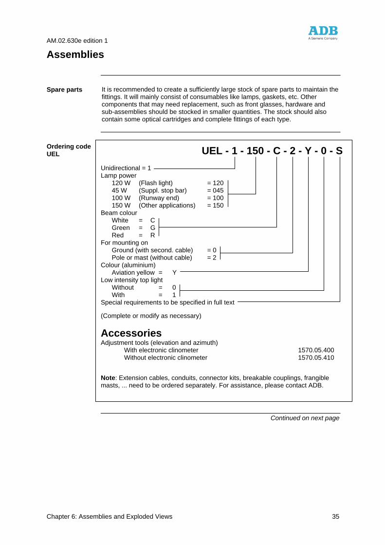
Assemblies
It is recommended to create a sufficiently large stock of spare parts to maintain the fittings. It will mainly consist of consumables like lamps, gaskets, etc. Other components that may need replacement, such as front glasses, hardware and sub-assemblies should be stocked in smaller quantities. The stock should also contain some optical cartridges and complete fittings of each type.
Continued on next page
Spare parts
Ordering code UEL UEL - 1 - 150 - C - 2 - Y - 0 - S
Unidirectional = 1 Lamp power 120 W (Flash light) = 120 45 W (Suppl. stop bar) = 045 100 W (Runway end) = 100 150 W (Other applications) = 150 Beam colour White = C Green = G Red = R For mounting on Ground (with second. cable) = 0 Pole or mast (without cable) = 2 Colour (aluminium) Aviation yellow = Y Low intensity top light Without = 0 With = 1 Special requirements to be specified in full text (Complete or modify as necessary)
Accessories Adjustment tools (elevation and azimuth) With electronic clinometer 1570.05.400 Without electronic clinometer 1570.05.410
Note: Extension cables, conduits, connector kits, breakable couplings, frangible masts, ... need to be ordered separately. For assistance, please contact ADB.
AM.02.630e edition 1
Chapter 6: Assemblies and Exploded Views 36
Assemblies, continued
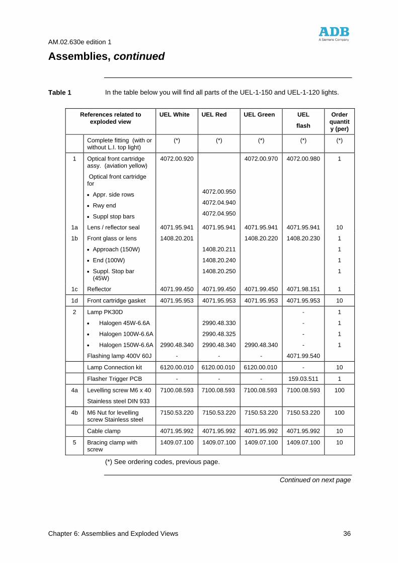
In the table below you will find all parts of the UEL-1-150 and UEL-1-120 lights.
(*) See ordering codes, previous page.
Continued on next page
References related to exploded view
UEL White UEL Red UEL Green UEL
flash
Order quantity (per)
Complete fitting (with or without L.I. top light)
(*) (*) (*) (*) (*)
1 Optical front cartridge assy. (aviation yellow)
Optical front cartridge for
• Appr. side rows
• Rwy end
• Suppl stop bars
4072.00.920
4072.00.950
4072.04.940
4072.04.950
4072.00.970 4072.00.980 1
1a Lens / reflector seal 4071.95.941 4071.95.941 4071.95.941 4071.95.941 10
1b Front glass or lens
• Approach (150W)
• End (100W)
• Suppl. Stop bar (45W)
1408.20.201
1408.20.211
1408.20.240
1408.20.250
1408.20.220 1408.20.230 1
1
1
1
1c Reflector 4071.99.450 4071.99.450 4071.99.450 4071.98.151 1
1d Front cartridge gasket 4071.95.953 4071.95.953 4071.95.953 4071.95.953 10
2 Lamp PK30D
• Halogen 45W-6.6A
• Halogen 100W-6.6A
• Halogen 150W-6.6A
Flashing lamp 400V 60J
2990.48.340
-
2990.48.330
2990.48.325
2990.48.340
-
2990.48.340
-
-
-
-
-
4071.99.540
1
1
1
1
Lamp Connection kit 6120.00.010 6120.00.010 6120.00.010 - 10
Flasher Trigger PCB - - - 159.03.511 1
4a Levelling screw M6 x 40
Stainless steel DIN 933
7100.08.593 7100.08.593 7100.08.593 7100.08.593 100
4b M6 Nut for levelling screw Stainless steel
7150.53.220 7150.53.220 7150.53.220 7150.53.220 100
Cable clamp 4071.95.992 4071.95.992 4071.95.992 4071.95.992 10
5 Bracing clamp with screw
1409.07.100 1409.07.100 1409.07.100 1409.07.100 10
Table 1
AM.02.630e edition 1
Chapter 6: Assemblies and Exploded Views 37
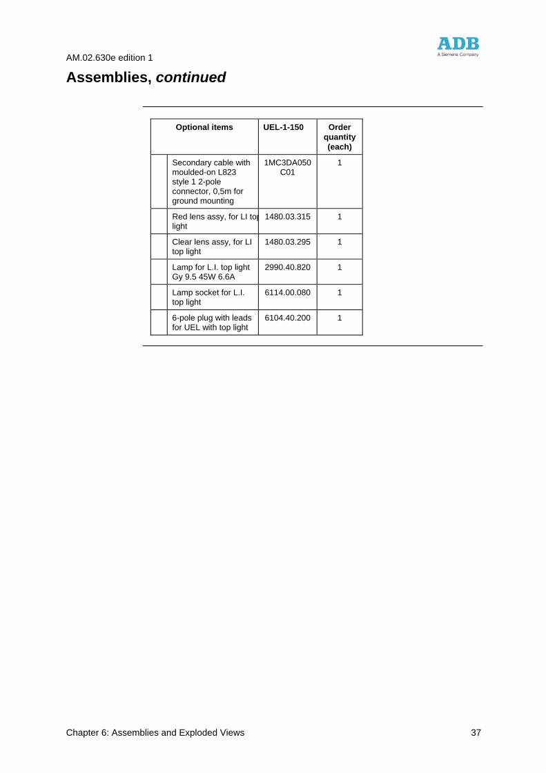
Assemblies, continued
Optional items UEL-1-150 Order
quantity (each)
Secondary cable with moulded-on L823 style 1 2-pole connector, 0,5m for ground mounting
1MC3DA050 C01
1
Red lens assy, for LI toplight
1480.03.315 1
Clear lens assy, for LI top light
1480.03.295 1
Lamp for L.I. top light Gy 9.5 45W 6.6A
2990.40.820 1
Lamp socket for L.I. top light
6114.00.080 1
6-pole plug with leads for UEL with top light
6104.40.200 1
AM.02.630e edition 1
Chapter 6: Assemblies and Exploded Views 38
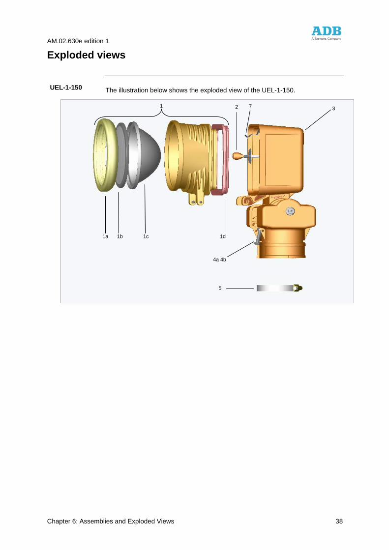
Exploded views
The illustration below shows the exploded view of the UEL-1-150.
Herebelow the execution with low intensity top light.
Continued on next page
UEL-1-150
1a 1b 1c 1d
2
4a 4b
5
1 3 7
AM.02.630e edition 1
Chapter 6: Assemblies and Exploded Views 39
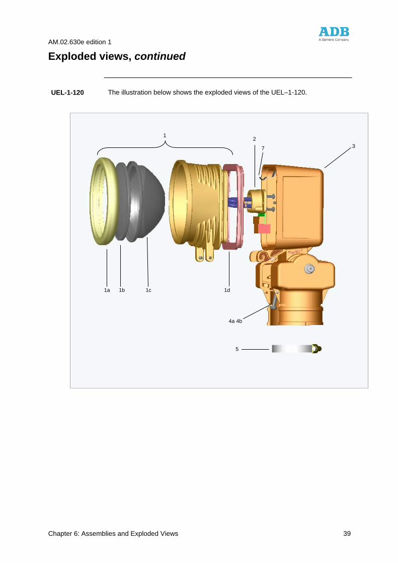
Exploded views, continued
The illustration below shows the exploded views of the UEL–1-120.
UEL-1-120
2
4a 4b
5
1
3
1a 1b 1c 1d
7
AM.02.630e edition 1
Chapter 6: Assemblies and Exploded Views 40
N.V. ADB S.A. Leuvensesteenweg, 585 – B 1930 Zaventem – Belgium Tel. : 32/2/722.17.11 – Fax : 32/2/722.17.64 Companies in France, U.K. and U.S.A. – Agents all over the world

![UEL Library Search [Catalogue]](https://static.fdocuments.in/doc/165x107/56812d9d550346895d92bb8a/uel-library-search-catalogue.jpg)


![WELCOME! [] · or in print form. See the UEL website for more information. • Review the UEL website for materials and content. • Visit the UEL office to view the application and](https://static.fdocuments.in/doc/165x107/5e96faee3df7f64bc756d11d/welcome-or-in-print-form-see-the-uel-website-for-more-information-a-review.jpg)