UBMITTED TO - Gov
27
Transcript of UBMITTED TO - Gov


ii
SUBMITTED TO MANITOBA CONSERVATION ON BEHALF:
URBANMINE INC. ENVIRONMENT ACT PROPOSAL Scrap Metal Processing Facility 72 Rothwell Road City of Winnipeg
APRIL, 2014 Prepared by: D. Ediger Consult ing Services
:

iii
T A B L E O F C O N T E N T S
1.0 INTRODUCTION ...................................................................................................................... 1 2.0 DESCRIPTION OF DEVELOPMENT ...................................................................................... 2
2.1 PROPERTY OWNERSHIP ............................................................................................................. 2 2.2 LAND USE DESIGNATION ............................................................................................................. 2 2.3 ADJOINING PROPERTIES ............................................................................................................. 2 2.4 PROXIMITY TO RESIDENCES ........................................................................................................ 2 2.5 SITE ACCESS .............................................................................................................................. 2 2.6 FACILITY DESIGN ....................................................................................................................... 3
2.6.1 FERROUS SCRAP YARD ........................................................................................................... 3 2.6.2 VEHICLE STORAGE & PROCESSING AREA .................................................................................. 3 2.6.3 MATERIAL HANDLING & PROCESSING EQUIPMENT ...................................................................... 3 2.6.4 NON FERROUS METAL RECEIVING AND STORAGE AREA ............................................................... 4
2.7 STAFF FACILITIES ....................................................................................................................... 4 2.8 FIRE PROTECTION ...................................................................................................................... 4
3.0 SITE OPERATION ................................................................................................................... 5 3.1 RECEIVING SHIPMENTS .............................................................................................................. 5
3.1.1 FERROUS METAL .................................................................................................................... 5 3.1.2 VEHICLES ............................................................................................................................... 5 3.1.3 NON-FERROUS METALS ........................................................................................................... 5
3.2 FERROUS METAL PROCESSING .................................................................................................... 5 3.3 VEHICLE PROCESSING ................................................................................................................ 6 3.4 OPERATING HOURS .................................................................................................................... 6
4.0 ENVIRONMENTAL SETTING ................................................................................................. 7 4.1 TOPOGRAPHY ............................................................................................................................ 7 4.2 SUBSURFACE DESCRIPTION ........................................................................................................ 7 4.3 PREVIOUS LAND USE .................................................................................................................. 7 4.4 SITE DESIGNATIONS ................................................................................................................... 7
5.0 ENVIRONMENTAL IMPACTS AND MITIGATION MEASURES ............................................ 8 5.1 NOISE ........................................................................................................................................ 8
5.1.1 POTENTIAL IMPACTS ................................................................................................................ 8 5.1.2 MITIGATION ............................................................................................................................. 8
5.2 AIRBORNE PARTICULATE ............................................................................................................. 9 5.2.1 POTENTIAL IMPACTS ................................................................................................................ 9 5.2.2 MITIGATION ............................................................................................................................. 9
5.3 GROUNDWATER ......................................................................................................................... 9 5.3.1 POTENTIAL IMPACTS ................................................................................................................ 9 5.3.2 MITIGATION ............................................................................................................................. 9
5.4 SURFACE WATER ..................................................................................................................... 10 5.4.1 POTENTIAL IMPACTS .............................................................................................................. 10
iv
5.4.2 MITIGATION ........................................................................................................................... 10 6.0 EMERGENCY PLANNING .................................................................................................... 12 7.0 DECOMMISSIONING ............................................................................................................ 13
FIGURES
APPENDIX A: PROPERTY CERTIFICATE OF TITLE
1
1.0 I N T R O D U C T I O N
Urbanmine Inc. operates a scrap metal processing facility at 72 Rothwell Road in the City of Winnipeg. The site is on a 2 hectare parcel of land in an industrial area.
Scrap metal is delivered to the site by truck and is sorted and processed prior to being shipped to other recycling facilities. Ferrous metal processing steps may include size reduction using a fixed or mobile shear or a cutting torch and sorting into various scrap grades. Ferrous metal is stored outdoors on an unpaved lot. Non-ferrous metals, including automotive batteries are generally stored in the building on the east side of the property. Potential environmental impacts resulting from the operation of the Urbanmine facility are related primarily to noise levels and surface drainage. The company has taken steps to mitigate these impacts and is in the planning stage for further site improvements to address any environmental issues.

2
2.0 D E S C R I P T I O N O F D E V E L O P M E N T
2 . 1 P R O P E R T Y O W N E R S H I P
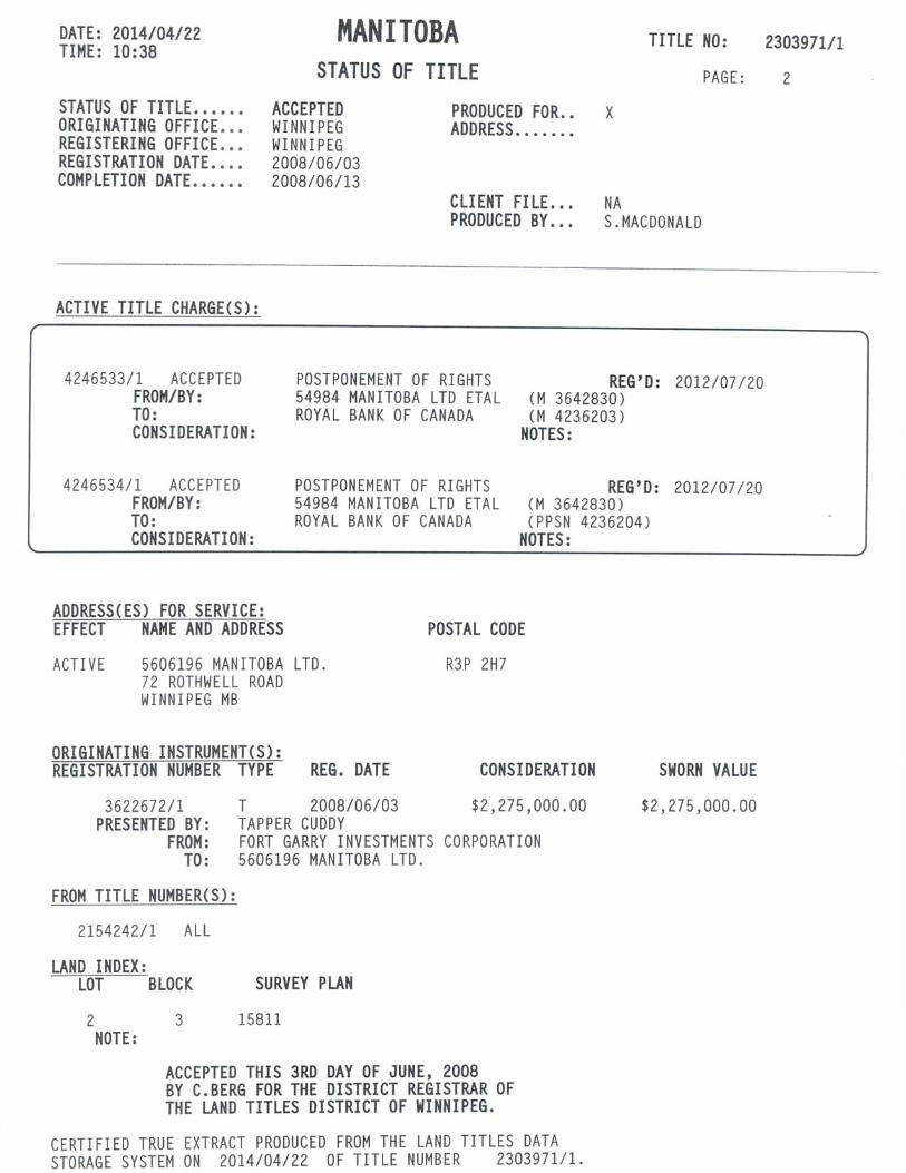
The Urbanmine facility is situated on approximately 2 hectares of land located at 72 Rothwell Road in the City of Winnipeg. The location is shown on Figure 1. The land is owned by Urbanmine Inc. A copy of the current Status of Title is included as Appendix A.
2 . 2 L A N D U S E D E S I G N A T I O N
According to the City of Winnipeg website the property is zoned as M3, Manufacturing - Heavy
2 . 3 A D J O I N I N G P R O P E R T I E S
The properties immediately adjacent to the parcel of land where the development is being proposed are described as follows: North: Warehouse East: CN Rail Line, CP Rail Line South: Rothwell Road, West: Lowson Cres., equipment dealer, private gym, one building currently
vacant
2 . 4 P R O X I M I T Y T O R E S I D E N C E S
The closest residential area to the Urbanmine facility is the Lindenwoods development located to the east. The closest residence is located approximately 175 metres from the centre of the Urbanmine property.
2 . 5 S I T E A C C E S S
The Urbanmine site is accessed from the south side of the property on Rothwell Road as shown on Figure 1. Truck traffic enters and exits Rothwell Road at Kenaston Ave. Traffic volumes coming to and from the site are estimated at 30 to 100 vehicles per day with the highest volumes occurring during the summer months.

3
2 . 6 F A C I L I T Y D E S I G N
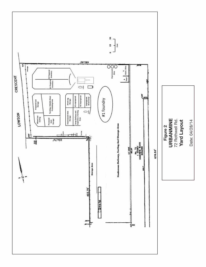
The Urbanmine facility consists of an outdoor yard where ferrous scrap metal is managed and a building. The building, which is used for storage of non-ferrous products and for office and staff space, extends along the entire east property line. A truck scale is located inside the entrance gate on the south end of the yard. The yard layout is shown in Figure 2.
2.6.1 FE R R O U S S C R A P Y A R D
The north and west perimeters of the yard where scrap is being stored and handled is surrounded by a 3 metre high solid fence. The north portion of the yard is used for stockpiling of unprocessed and processed ferrous metal.
2.6.2 V E H IC LE S TO R A G E & P R O C E S S IN G A R E A
Scrap vehicles are stored in a designated portion of the ferrous scrap yard prior to processing. Adjacent to the storage area is the "car evac” area where fluids and other hazardous components are removed for the vehicle before it placed in the crusher. Tanks and containers for storing the products removed from the vehicle are located in the car evac area. Currently this area is situated on a slag aggregate base.
2.6.3 M A T E R IA L H A N D L IN G & P R O C E S S IN G E Q U IP M E N T Ferrous scrap is handled and processed in the yard using various types of equipment as listed below.
• 2 - 934A Liebherr material handlers • 1 - 924A Liebherr material handler • 1 - Volvo L90 Wheel Loader • 1 - 780E Gehl Skidsteer • 1 - T750 SL Sierra Shear • 1 - E-Z Crusher Logger/Baler • 1 - Hitachi 270 with Genesis Shear • 1 – Overbilt Car Crusher Material handlers are equipped with grapples to pick up and move scrap metal through the various stages of sorting and processing. The shear is used to reduce metals pieces to standard sizes for shipping to downstream processers. All of the listed pieces of equipment area gasoline or diesel powered with the exception of the shear, which is operated by an electric motor. Metal cutting in the yard is also carried out using oxy-propane or plasma cutting torches or a mobile shear.

4
2 .6.4 N O N F E R R O U S M E T A L R E C E IV IN G A N D S TO R A G E A R E A
Loads of non-ferrous scrap are brought to the loading dock on the west side of the building as indicated in Figure 1. Most incoming material is sorted and stored in the building prior to shipping to processers.
2 . 7 S T A F F F A C I L I T I E S
Approximately 35 staff are employed at the Urbanmine facility. All staff facilities are located within the main building.
2 . 8 F I R E P R O T E C T I O N
One fire hydrant is located in the yard and additional fire hose connections are accessible at the building. Fire extinguishers are maintained in strategic locations in the yard and building. Two additional fire hydrants are situated immediately adjacent to the Urbanmine property.
5
3.0 S I T E O P E R A T I O N
3 . 1 R E C E I V I N G S H I P M E N T S
All vehicles delivering materials to the Urbanmine site are required to check in with staff at the scale office. After the contents of the load have been confirmed, the delivery vehicle will be directed to the appropriate location for unloading. A hand held radiation detection unit is kept on site to scan incoming loads or individual components if required
3.1.1 FE R R O U S M E TA L
Incoming loads of ferrous scrap are placed in the designated yard area for unsorted scrap as indicated in Figure 2. Trucks are unloaded using the site’s material handlers.
3.1.2 V E H IC LE S
Scrap vehicles delivered to the site are placed in a designated area as indicated in Figure 2.
3.1.3 N O N-F E R R O U S M E T A LS
Non-ferrous scrap is delivered to the loading dock on the main building. These materials are categorized and stored in the building pending shipment to a recycling facility. Some non-ferrous metals are sorted and baled outside of the building adjacent to the loading dock.
3 . 2 F E R R O U S M E T A L P R O C E S S I N G
Ferrous scrap taken from the inspection/sorting area is separated into one of several storage piles in the yard depending on the classification of the material. Large pieces of metal are fed through the shear to reduce the size for more efficient shipping and processing. Prepared ferrous scrap is placed in designated storage areas pending shipment to a recycler.

6
3 . 3 V E H I C L E P R O C E S S I N G
Prior to being placed into the crusher unit, vehicles are processed by Urbanmine staff to remove hazardous components. Processing includes the following steps:
• removal of any remaining fuel • removal of mercury switches • removal of catalytic converters • removal of lead acid batteries • draining antifreeze from radiators • checking trunks and interiors for hazardous materials (e.g. propane tanks) which
may have been left in the vehicle Following these processing steps, the vehicle hulk is placed in the crusher and flattened using a diesel powered Overbuilt crusher unit. In some instances the Sierra Shear is used to bale vehicles. The vehicle is placed in the processed auto storage area pending shipment off site.
3.4 OPERATING HOURS
The Urbanmine facility operates on Monday to Saturday 7:00 a.m. to 9:00 p.m.
7
4.0 E N V I R O N M E N T A L S E T T I N G
4 . 1 T O P O G R A P H Y
The Urbanmine site and adjoining properties are relatively flat prairie with no significant elevation fluctuations. Original land features and surface drainage patterns have been altered by urban development in the general area.
4 . 2 S U B S U R F A C E D E S C R I P T I O N
There are no identified wells located on the property. A search of the Manitoba government’s GWDrill database did not record any well locations in the vicinity of the Urbanmine site. The soil stratigraphy described in the GWDrill database for wells in the south western part of Winnipeg typically consist of 30 to 35 ft. of clay underlain by 10 to 20 ft. of till/gravel over the limestone formation which is the primary water bearing formation. Due to the relative consistency in well logs for the general area, it is assumed that a similar soil structure exists under the Urbanmine site.
4 . 3 P R E V I O U S L A N D U S E
The site on the current Urbanmine facility was originally developed as a trucking operation. No major changes have been made to the structure on the site.
4 . 4 S I T E D E S I G N A T I O N S
Based on information on the Government of Manitoba website, the Urbanmine site is not in the vicinity of any designated protected areas or historic sites.

8
5.0 E N V I R O N M E N T A L I M P A C T S A N D M I T I G A T I O N M E A S U R E S
5 . 1 N O I S E
5.1.1 P O TE N TIA L IM P A C TS
Elevated sound levels have the potential to have an adverse impact on residential occupants and commercial operations in the vicinity of the sound source. In the case of the Urbanmine facility, the closest residential development is 175 metres east of the centre of the outdoor processing area. It is noted that the space between the Urbanmine property and the residential development includes two railway lines which can also contribute to elevated sound levels in the area on an intermittent basis. The primary sound sources at the Urbanmine site include the handling of ferrous scrap outdoors, the operation of the shear and the engines in the equipment operating on the site.
5.1.2 M IT IG A T IO N
The handling of scrap metal, such as extracting metal pieces from a stockpile, will result in sound generation regardless of how diligent the equipment operator is. Some material will fall from the grapple during handling and the only mitigation option is to minimize the height to which the material is lifted. The manufacturer’s data on the motorized equipment used on the site indicates an average sound level outside the machine of approximately 95 to 105 dBA. The building located on the east side of the property is expected to provide some measure of sound reduction between the sound source and the adjacent residential development. Based on data published in other North American jurisdictions, sound levels in the residential area resulting from activities at the Urbanmine facility are projected to be in the 70 to 75 dBA range, although these figures can only be considered to be an approximate initial estimate. Urbanmine has acquired instrumentation for measuring sound levels and will be recording sound levels at the facility and in the surrounding area starting in the spring of 2014.

9
5 . 2 A I R B O R N E P A R T I C U L A T E
5.2.1 P O TE N TIA L IM P A C TS
Particulate emission sources at the Urbanmine facility include: • road dust raised by vehicles driving through the facility • dust generated from scrap loads being unloaded from delivery vehicles.
5.2.2 M IT IG A T IO N
Road dust is minimized through the application of magnesium chloride as a dust suppressant on unpaved surfaces in traffic areas. Dust generated from unloading operations can be minimized by misting the area with a water spray during unloading. This option would only be required for loads originating in conditions where the scrap includes mud and other similar debris. The decision to mist a load would be at the discretion of the Urbanmine staff based on previous experience with shippers and scrap sources.
5 . 3 G R O U N D W A T E R
5.3.1 P O TE N TIA L IM P A C TS
Potential groundwater contaminants resulting from the operation of the development consist primarily of fluids contained in the vehicles brought on to the site. Fluids could be released accidentally during the depolluting of vehicles or while the fluids are in storage pending removal from the site.
5.3.2 M IT IG A T IO N
• The depth of clay cover over the limestone aquifer under the site provides a significant degree of protection from any contaminants released on the ground surface.
• Fluids will be stored in appropriate containers • A paved pad will be installed for the vehicle evac area to ensure that any spilled
fluids can be contained and recovered before they migrate into the subsurface • The emergency plan developed for the facility includes procedures for
responding to spills. Absorbent and/or neutralizing products to contain and recover spilled materials before they can impact the environment will be kept available on site.

10
5 . 4 S U R F A C E W A T E R
5.4.1 P O TE N TIA L IM P A C TS
Runoff water from the development site can potentially carry contaminants from the areas where scrap metals and other materials associated with the site operation are stored. The most probable contaminants are metals and hydrocarbons. Metals could be introduced into surface runoff as corrosion products from the metal storage areas and in particulate matter from the shear operation. Sources of hydrocarbons that could potentially impact surface runoff would include leakage from vehicles stored at the site and from leaks or spills during the handling of oil, fuels and other fluids during the depollution processes. The design of the fluids recovery processes and storage systems has been completed in accordance with sound industry practices and is expected to meet all applicable regulatory standards. Surface water runoff from the site is not expected to impact the aquatic environment, based on the distance to the nearest surface water features that support aquatic life. Currently, surface water runoff from the southern half of the site is directed to the drainage ditch at the southwest corner of the property. This ditch then flows west along the north side of Rothwell Road for a short distance before an underground drainage pipe carries the flow to the south side of Rothwell. The northern portion of the site is drained by a ditch along the north edge of the site that flows both west to Lowson Crescent and east towards the rail line. Another ditch that flows west to Lowson Crescent is located south of the vehicle evacuation process (bordering 207 Lowson Crescent). A recent examination of the site drainage for the Urbanmine site revealed possible infiltration of surface water from some of the adjoining properties. Further work will be conducted to determine the effect of this infiltration on the Urbanmine site and the need to take corrective measures.
5.4.2 M IT IG A T IO N
Urbanmine has recently completed site drainage and process modifications to minimize the release of contaminants from the site via the surface water drainage pathway. This has included:
• Constructing a perimeter roadway around the vehicle processing and shear location at the northwest corner of the property to act as a berm in order to reduce/eliminate surface runoff from leaving the facility to the west and north.

11
• Removing a temporary stormwater drainage pipe that previously discharged site runoff from the northwest corner of the site to the drainage ditch located at the north property limit.
• Relocating the used oil filter recovery and consolidation operations away from the drainage ditch at the southwest corner of the property.
• Undertaking a site elevation survey to establish the surface runoff characteristics of the site to more fully understand and control site drainage. The surface drainage map developed from this survey is shown as Figure 3
• Retaining an engineering consultant to undertake site runoff sampling in the spring of 2014 in order to develop additional surface water management and mitigation options for the property, if necessary. The site runoff monitoring includes collecting four surface water samples from the drainage ditches at the southwest corner, northwest corner (two samples) and northeast corner of the property to characterize the quality of the runoff leaving the property for the potential contaminants identified above. The water quality results will be compared with the existing City of Winnipeg Limits for Discharges to the Land Drainage System contained in Schedule D of the City of Winnipeg Sewer By-Law (No. 92/2010).
12
6.0 E M E R G E N C Y P L A N N I N G
Urbanmine has developed an emergency response plan (ERP) for the facility. Specific sections in the plan address fire and hazardous material spills
All Urbanmine employees working at the facility are trained on the contents of the ERP. The ERP will be reviewed and updated as required on an annual basis.

13
7.0 D E C O M M I S S I O N I N G
A preliminary decommissioning plan will be prepared shortly after the facility is operational. The plan will identify the key areas to be addressed including potential environmental impacts and restoration of the site to its previous condition. The decommissioning plan will generally follow the procedures described in the National Guidelines for Decommissioning Industrial Sites (CCME, 1991).

14
DISCLAIMER
This report was prepared by D. Ediger Consulting Services. Although all reasonable efforts were made to ensure the scientific accuracy and completeness of the information provided, D. Ediger Consulting Services makes no warranty, expressed or implied, as to the overall impact of the Development described in this proposal.

FIGURES

Fig
ure
1U
RB
AN
MIN
E72
Rot
hwel
l Rd
.S
ite
Loca
tio
n
Dat
e: 0
4/28
/14
Entrance
Fig
ure
2U
RB
AN
MIN
E72
Rot
hwel
l Rd
.Ya
rd L
ayo
ut
Dat
e: 0
4/28
/14

Fig
ure
3U
RB
AN
MIN
E72
Rot
hwel
l Rd
.Ya
rd D
rain
age
Co
nto
urs
Dat
e: 0
4/28
/14
A P P E N D I X A
Certificate of Title