.u. - NASA · ambient pressure. Application of Bernoulli's equation indicates that this is...
41
AN ANALYTICAL INVESTIGATION OF THE IMPINGEMENT OF JETS ON CURVED DEFLECTORS N. M. Schnurr* + J. W. Williamson =I J. W. Tatom (NASA-CR-129136) AN ANALYTICAL INVESTIGATION OF THE IMPINGEMENT CURVED DEFLECTORS N M S h ( .u. c nurr, Vanderb11t Univ.) [1972] 41 P JETS ON et al CSCL 20D G3/12 N73-11252 Unclas 16655 / /' Vanderbilt University Nashvillf;l, Tennessee This work was supported by NASA Grant NGR-43-003-034. Th e authors wish to acknowledge the contributions of Larry J. HucY whose work led to the research reported here. AIRCHAFT DECELERATION SYSTEMS *Associate Professor of Mechanical Engineering +Associate Professor of Mechanical Engineering IAssociate Professor of IvIechanical Engi.neering, Member 1\1/..A . - - - . ---- ,.- REPRODUCED BY NATIONAL TECHNICAL INFORMATION SE.RVICE u.s. DEPARTMENT OF COMMERCE SPRINGFIELD, VA 22161 . https://ntrs.nasa.gov/search.jsp?R=19730002525 2020-02-13T12:02:47+00:00Z
Transcript of .u. - NASA · ambient pressure. Application of Bernoulli's equation indicates that this is...

AN ANALYTICAL INVESTIGATION OF THE IMPINGEMENT
OF JETS ON CURVED DEFLECTORS
N. M. Schnurr*
+J. W. Williamson
=IJ. W. Tatom
(NASA-CR-129136) AN ANALYTICALINVESTIGATION OF THE IMPINGEMENTCURVED DEFLECTORS N M S h( .'~ .u. c nurr,
Vanderb11t Univ.) [1972] 41 P
JETS ONet al
CSCL 20DG3/12
N73-11252
Unclas16655
//'
Vanderbilt UniversityNashvillf;l, Tennessee
This work was supported by NASA Grant NGR-43-003-034. Th e authorswish to acknowledge the contributions of Larry J. HucY whose work ledto the research reported here.
AIRCHAFT DECELERATION SYSTEMS
*Associate Professor of Mechanical Engineering
+Associate Professor of Mechanical Engineering
IAssociate Professor of IvIechanical Engi.neering, Member 1\1/..A
. - - - ~. ---- ,.-
REPRODUCED BYNATIONAL TECHNICALINFORMATION SE.RVICE
u.s. DEPARTMENT OF COMMERCESPRINGFIELD, VA 22161 .
https://ntrs.nasa.gov/search.jsp?R=19730002525 2020-02-13T12:02:47+00:00Z

ABSTRACT
Numerical solutions are obtained for the cases of straight circular
jets impinging on axisymmetric curved surfaces and plane jets impinging
symmetrically on two-dimensional curved surfaces ~ These geometries are
representative of some types of thrust reversers for transport aircraft.
The solutions are based on the assumptions of incompressible am potential
flow. The velocity field, pressure distribution at the deflector surface
and reverser effectivenes s are predicted for deflector turning angles of
150 to 75 0, deflector width to jet diameter ratios -of 1.5 to 2.0, and ratios
of deflector clearance to jet diameter of 1.0 to 3.0. Reverser effectiveness
is found to be a maximum for a ratio of deflector clearance to jet diameter
of about 2.0. The effect of back pressuring due to the presence of the
deflector is predicted. Experimental verification of the theoretical pre
dictions is obtained. A compressible solution obtained for a limited
number of cases indicates that the incompressible solution is satisfactory
for jet exit Mach numbers less than 0.8.
Preceding page blank-,ii
c
h
n
P
Pco
s
...v
vs
x
NOMENCLATURE
Local sonic velocity (ft/sec)
Deflector depth (ft)
Jet half width (ft)
Length of duct from which jet flows (ft)
Jet exit to deflector spacing (ft)
Reflector wid th (ft)
Normal distance (ft)
Pressure (lb/ft2
)
Static pressure (lb/ft2
)
2 .Ambient pressure (lb/ft )
Tangential distance (ft)
Velo/clty (ft/sec)
Magnitude of the velocity along the free streamline (ft/sec)
Distance measured from the stagnation point normal to the jet
symmetry line or plane (ft)
y Distance measured from the stagnation point along the jet
symmetry line or plane (ft)
T1 Reverser effectiveness
T\r Turning effectiveness
iii

e Deflector turning angle
p Fluid density (lb /ft3
)m
¢ Dimensionless velocity potential = "¢/VsLl
¢ 2Velocity potential (ft /sec)
iv

1
INTROD DCTIO N
The purpose of the work described in this paper is to provide an
analytical method for predicting the flow field and resulting forces pro-
duced by the impingement of a jet on a curved surface. The shapes of the
surfaces investigated are representative of a type of thrust reverser
proposed for STOL and conventional aircraft. The analytical method is
~hen used to predict the effects of several geometrical parameters on
revers er performa nee.
The authors are not aware of any previous analytical solutions of
jets impinging on curved surfaces. A variety of methods have been used
to study the impingement of axisymmetric or plane jets on flat surfaces
D. -6] *. In all of these analyses the flow was assumed potential and
incompressible. The work which most closely approximates the case of
a curved deflector is that of Chang and Conly C7 ] and Chang and
Waidelich [8]. They used conformal mapping to solve the case of the
deflection of an incompressible I two-dimensional jet by a series of
straight segments of arbitrary number I length I and angles. This work is
limited to incompressible plane jets of uniform velocity I however I and
the effects of back pressuring are not included.
*Numbers in brackets designate references at end of paper.

The present authors have recently attempted to develop an
analytical solution similar to that used by Shen [1] and apply it to the
cases of a circular radial jet impinging on a hemispherical surface and
a plane radial jet impinging on a cylindrical surface [9 I 10]. Series
solutions were obtained for both cases but were not satisfactory from a
practical standpoint due to the extremely large size of the coefficients
and erratic behavior in certain regions of the flow.
All of the analytical methods referred to above are limited to the
simplest geometries and could not be applied to target thrust reversers
of arbitrary shape. It is unlikely that a closed form solution applicable
to a variety of thrust reverser shapes is possible and it appears that a
purely numerical method is the best approach.
/,/
2

3
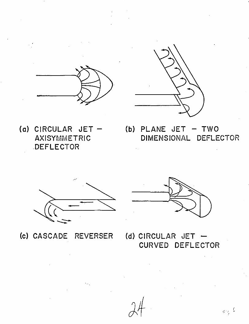
GEOMETRICAL CONFIG URATIONS
Analytical solutions were obtained for both straight circular jets
impinging on axisymmetric curved surfaces and plane jets impinging
symmetrically on two-dimensional curved surfaces. These two cases are
. illustrated in Figure 1 (a) and (b). The circular jet case (a) is repre-
sentative of a type of thrust reverser which has received some con-
sideration. The plane jet case (b) is not an exact representation of a
practical target thrust reverser but is nevertheless of interest for several
reasons. First of all, by proper selection of the shape, the deflector
may correspond to a type of cascade thrust reverser, Figure 1 (c).
Secondly I it may give at least qualitative information for the performance
of the type of target thrust reverser shown in Figure 1 (d). Finally,
case (b) is easier to duplicate experimentally for the purpose of checking/
/'
the validity of the inviscis flow assumption used in the analysis.
It should be noted that most target thrust reversers produce three-
dimensional flows (i.e. the velocity potential is a function of three
independent space coordina tes). A three-dimensional solution is
exceedingly complex and beyond the scope of the present analysis.
Nevertheless, the solutions reported here may be considered to be
elements of most three-dimensional cases and may yield qualitatively
useful results.

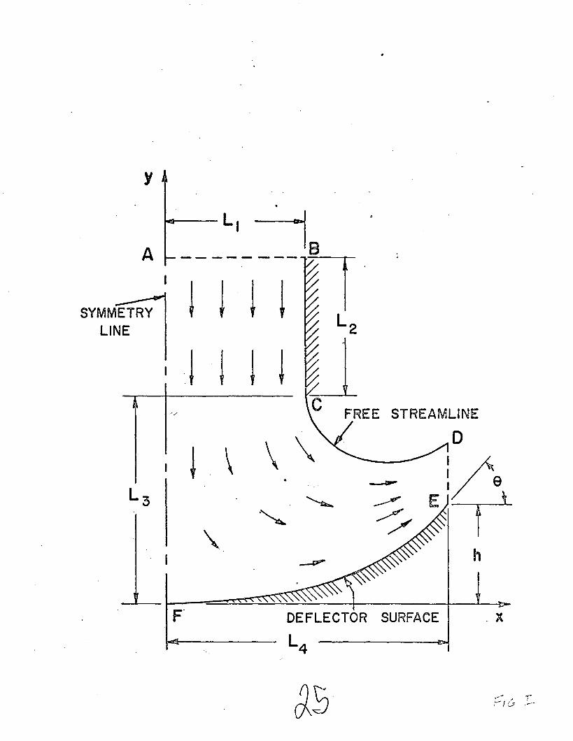
ANALYTICAL METHOD
The flow region to be analyzed is shown in Figure 2. This
diagram serves for both the circular and plane jet cases with the
distance Ll
being either the jet radius or half width depending on which
case is being considered. The analytical procuedure is discussed only
for the plane jet solution since the procedure for the circular jet case
is essentially the same with minor modifications to account for the
different geometry.
The analysis is based on the assumptions of incompressible I
inviscid and irrotational flow. Therefore I the flow field is completely
specified when the velocity potential field is known. The governing
differential equation for the velocity potential is the Laplace equation
A dimensionless velocity potential may be defined as
where Ll
is the jet half width and V is the velocity at point C. Thes .
nondimensional velocity potential also satisfies Laplace's equation
4
5
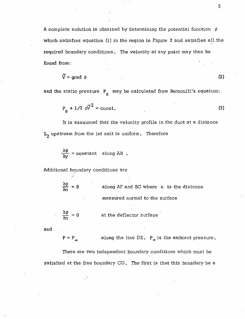
A complete solution is obtained by determining the potential function ¢
which s'atisfies equation (1) in the region in Figure 2 and satisfies all the
required boundary conditions. The velocity at any point may then be
found from:
--V = grad ¢ (2)
and the static pressure P may be calculated from Bernoulli ,'s equation:s
--2P + 1/2 pV = const.s
It is assuumed that the velocity profile in the duct at a distance
L2
upstream from the jet exit is uniform. Therefore
~¢ = constant along AB •uy
Additional boundary conditions are/"
/
(3)
and
o¢ = 0on
o¢= 0on
P=Pco
along AF and Be where n is the distance
measured normal to the surface
at the deflector surface
along the line DE. P (Xl is the ambient pres sure.
There are two independent boundary conditions which must be
satisfied at the free boundary CD. The first is that this boundary be a

6
streamline. This condition may be stated mathematically as
M. = 0on where n is the distance normal to the streamline.
Therefore I lines of constant potential intersect the free boundary at
right angles. The other condition is that the pressure be equal to the
ambient pressure. Application of Bernoulli's equation indicates that this
is equivalent to specifying a constant velocity along the streamline.
The second condition for the free boundary is, then
o¢ = VOS s
where s is distance measured tangentially along the curve and V iss
the velocity along the freestream boundary.
The major difficulty in solving this type of problem arises from/
/'
the fact that the location of the free streamline is unknown. The pro-
cedure used here is similar to a method which has been applied to flow
in a Borda mouthpiece and flow past an orifice plate by Southwell and
Vaisey Ul J. This procedure may be summarized as follows. A first
guess of the location of the freestream boundary is made. This original
estimate need not be very accurate but should have the qualitatively
correct shape. A rectangular mesh is then selected which is small
enough to produce at least 200 node points. Additional node points are
located at all intersections of the grid lines with the deflector and with

7
the free streamline. The values of velocity potential at the node points
on the free boundary are determined by using the constant velocity con-
dition along that 'line. The velocity potential is arbitrarily set equal to
zero at point C and values of ¢ are computed at successive points
along the boundary by using the relationship tl¢/t::.s = V where s iss
the distance measured along the curve.
A relaxation solution is used to obtain the velocity potential at
each node point in the flow field. It must then be determined whether
the assumed free boundary is the correct one. The remaining condition
which must be satisfied at the free boundary is that it be a streamline.
A necessary and sufficient condition is that a streamline be everywhere
normal to lines of constant ¢.
The method of checking this condition may be explained with the
aid of Figure 3., The slope (Sl) of the free streamline at point 1 is com-
puted in finite difference form. The ¢ value at point 1 is then compared
to values at 2, 3, and 4. It mus t fall between the values at 2 and 3 or
those at 3 and 4. * Linear interpolation is used to locate the point I'
which has the same value of velocity potential as point 1. The slope (S2)
*An exception may arise if the free boundary is nearly horizontal or has a
positive slope. Such cases are handled in a similar fashion using node
points below and to the right of the boundary point in question.

\
8
of a line normal to the line I' - 1 is computed. If 81 = 82 at all points
along the free boundary the solutionis complete. If not, the difference
in the slopes is used as a guide in reshaping the free streamline and the
process is repeated until a suitable solution is obtained.
Several checks were made to insure that the solution was satis-
factory. A criterion for sufficient relaxation was determined by carrying
out an extremely large number of iterations for a fixed boundary shape.
It was found that the relaxation was essentially complete when the change
in ¢ for successive iterations was less than .002% for every node point
in the grid. The necessary number of node points was determined by
successively increasing the number of node points and comparing the
solutions. About 15 divisions in both the x and y direction were
sufficient./
The boundary shape adjusted in an orderly fashion and did not
change appreciably after about ten iterations. The final solution was
checked by plotting isopotential lines and streamlines for the entire
flow field as well as the pressure distribution along the solid surface and
jet symmetry line.
Before the analytical results are discussed, experimental
verification of the analysis will be presented.

9
Experimental Program
The purpos e of the experimental program was to examine the
validity of the potential flow assumption. Therefore I it was necessary
to determine deflector surface pressures I reverse thrust loads I and free
streamline location for comparison with the analytical results.
A nozzle that would produce a uniform free jet exit velocity
profile was designed and built. The deflector shapes which were
investigated were:
1. a symmetrical deflector of constant radius of curvature I
2. an asymmetrical deflector intended to model a cascade
thurs t revers er •
Figure 4 illustrates the apparatus used in generating the two-
dimensional jet. The flow of air was produced by a centrifugal blower./
/
Air flow rate was closely controlled by a sliding cover valve located a t the
blower exit. The air flowed through a horizontal 15 inch square duct
seven feet long before entering the convergen t nozzle. The two-
dimensional nozzle which was 15 inches long I was formed with an
elliptical pattern and produced a straight jet 1.5 inches wide and 16
inches long. This represents an aspect ratio of 10.7. Because of the
large area ratio between the inlet and exit of the nozzle (approximately
10) I the jet was symmetrical about the centerline and nearly uniform.
The variation in velocity across the center portion of the jet was less than
5%. Exit jet veloc'ities of 250 fps could be attained.

10
Two of the deflector models tested were cylindrical with a radius
of curvature of 13.5 inches and a height of 16 inches. One had a 45 o.
turning angle and the other a 150 turning angle. Each of these had a
plywood base covered with a surface of 1/16 inch thick plexiglas.
Pressure taps were angularly spaced from the centerline to the edge of the
deflector in the plane at the center of the deflector. The third deflector
model consisted of a wood structure covered with a smooth aluminum
sheet. The ends of these deflectors were covered to prevent any end
flow and provision was made for the velocity probe to be inserted from
the top.
All velocity measurements were made with United Sensor and
Control Corporation yaw probes. These were used to determine the total
pressure and static pressure with a strobotac, the fluid temperature at/
exit of the jet was measured by an iron-constantan thermocouple, and the
axial thrust exerted on the deflector surface was measured by a BLH
Electronics, Inc. ·load cell. The deflector surface pressures were used
as an alternate method of determining the total thrust load.
Results from the cylindrical deflector with a radius of 13.5 inches
and with an included angle of 30 0 are representative of the da ta obtained
in the experimental study. In this test, static and total pressures through-
out the field, deflector surface pressures, and the position of the edge
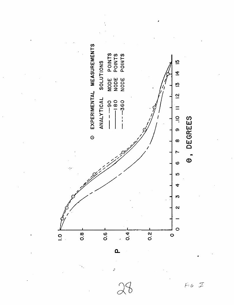
of the jet were measured. Figure 5 shows the deflector surface pressures

11
in dimensionless form for direct comparison to the predicted values of the
analytical method. The predicted values of pressure distribution are
quite sensitive to the number of node points used. The three predicted
curves were produced by using 90 I 180 and 360 node points in generating
solutions. The agreement between the experimental and predicted
pressures was very good when 180 or more node points were used. Figure
6 shows a comparison between the measured position and the predicted
position of the free streamline. Again, the agreement is excellent.
The measured position was quite sharp I and could be determined easily.
It is unfortunate that the edge of the jet could not be measured beyond
the x = 1.6 inches position because of the limitations of the measuring
ins trumenta tion.
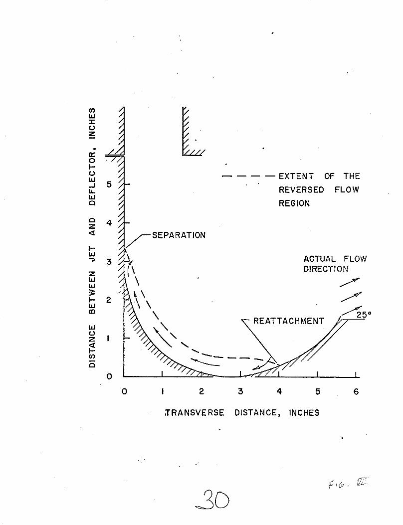
The last deflector shape investigated was the cascade thrus t//
reverser model .. A sketch of this model is presented in Figure 7 • This
reverser produced a deflector loading of 27 lb. at a flow rate of 2210 cfm.
Since the angle of the deflector (8) at exit was 54 0, the ideal reversed
thrust should have been 33.7 lb. The difference between these values
indicates a significant amount of spillage has occurred, and indeed this
result has been verified by making velocity traverses at the edge of the
deflector. The dimensionless deflector pressure ratio is plotted in
Figure 8 and compared with the analytical prediction. The predicted
results are generally much higher and the maximum variation between the

12
experimental and the theoretical results is about 28% 0 The reason for
this significant variation is separation that occurred in the curved portion
of the deflector surface because of the large adverse pressure gradient.
The size of the separation bubble was determined by flow visualization
and is shown in Figure 7.
The experimental tests indicate that the potential flow assumption
used in the analysis is justified for all two-dimensional cases which have
favorable pressure gradients along the deflector surface. However I in
those cases having adverse pressure gradients there is the likelihood that
separation will occur and the analytical solution discussed here is
inapplicable.
0 •• ".

.~ .
13
ANALYTICAL RESULTS
Solutions were obtained for a variety of geometries for both the plane
jet and circular jet cases. * The shape selected for a cross section of the
deflector was an ellipse having its center on the jet axis and passing
through points F and E (see Figure 2:). The additional requirement that the
slope of the deflector be a fixed value (tan 8) at E makes the curve unique.
The geometrical parameters which were specified include the non-dimensional
The results obtained for each case included the free streamline location,
the velocity potential field, the velocity vector at each node point, the
pressure distribution along the deflector surface and jet centerline, the
turning effectiveness, and the reverser effectiveness, 'll. The turning
effectiveness, 'llr' is defined as the ratio of reverse thrust to the momentum//
flux measured at the cross section a distance L2
upstream of the jet exit. It
may be calculated by simply determining the angle through which the flow is
turned. Comparison of actual turning effectiveness with the ideal turning
effectiveness which would result if the flow left the deflector exactly parallel
to the deflector surface is an indication of the spillage. The reverser effective-
ness, 'll, is the ratio of reverse thrust to the momentum flux which would exis t
at the jet exit cross section in the absence of back pressuring effects (i.e., if
the deflector were not present). It, therefore, includes the loss in thrust due
*These solutions are discussed in greater detail in reference 13.

14
to reduced flow caused by the back pressuring effect. The flow field and
pressure distributions for a typical case for a circular jet are shown in
Figures 9 and 10. .
A series of runs was made for both the plane and circular jet cases to
investigate the effects of geometry on performance. The results for all cases
are summarized in Table 1. The effect of jet exit to deflector spacing is per-
haps of most interest. The effect of this parameter on reverser performance i.s
shown in Figure 11 for the round jet case. The turning effectiveness increases
with decreasing jet to deflector spacing as expected since "spillage" is
decreased. There is, however, an accompanying decrease in mass flow rate
with decreased spacing causing an eventual decrease in reverser effectiveness.
Note than an optimum spacing occurs at a deflector to jet spacing of
approximately two. Povolny, et al [12] experimentally inves tigated the effect/'
/'
of jet to deflector spacing for the case of a round jet impinging on a hemi-
sphere. Although their case is not identical to the one considered here it is
quite similar. They found an optimum spacing of about 1.8 diameters.
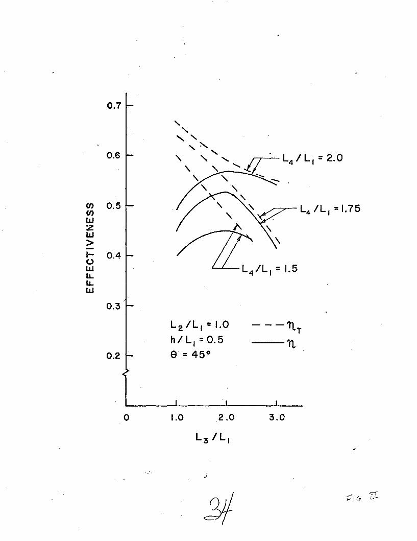
Th~ effect of deflector width is shown in Figure 12. Note that there is
little to be gained by increasing deflector width above about 1.75 diameters.
This conclusion is also in agreement with Povolny's experimental results.
Figure 12 also clearly illustrates the effect of back pressuring. A jet to
deflector spacing of one diameter gives much better turning effectiveness
than a spacing of two diameters but the higher back pressuring causes the
reverser effectivenes's to be lower.

TA8LE 1 - ANALYTICAL RESULTS
CIRCU IAR JET CASES
Case L IL L3(11 L/1 hiLl 8(0).z.. -l 4 .}
A-I 1.0 1.0 1.5 .5 45 .60 .40
A-2 1.0 1.5 1.5 .5 45 .54 .44
A-3 1.0 2.0 1.5 .5 45 .48 .45
A-4 1.0 2.5 1.5 .5 45 .44 .43
A-5 1.0 1.0 1.75 .5 45 .64 .45
A-6 1.0 1.5 1. 75 .5 45 .60 .51
A-7 .10 2.0 1. 75 .5 45 .56 .53
A-8 1.0 3.0 1. 75 .5 45 .43 042
A-9 1.0 1.0 2.0 .5 45 .66 .49j
A-I0 1.0 1.5 2.0 .5 45 .63 .55
A-II 1.0 2.0 2.0 .5 45 .59 .57
A-12 1.0 3.0 2.0 .5 45 .55 .54
A-13 2.0 /' 1.0 2.0 .5 45 .66 049,
A-14 1.0 1.5 1. 75 .5 60 .75 .64
A-IS 1.0 1.5 1. 75 .5 30 .42 .36
A-16 1.0 .1.5 1. 75 .5 75 .86 .73
PLANE JET CASES
8-1 2.0 2.0 2.0 .34 15 .19 .13
B-2 2.0 2.0 2.0 .34 30 .38 .28
8-3 2.0 2.0 2.0 .34 45 .53 .39
8-4 2.0 2.0 3.0 .80 30 .47 .34
8-5 2.0 3.0 3.0 .80 30 .45 .40
8-6 2.0 4.0 3.0 .80 30 .43 Al
8-7 2.0 5.0 3.0 .80 30 .41 AD
15

16
The effect of turning angle is illustrated in Figure 13. As 8 increases
'both the turning effectiveness and reverser effectiveness increase monotoni-
cally. The back pressuring loss shows essentially no increase with turning
angle for the geometry considered here.
The purpose of including a length of duct L2
was to investigate the
effect of back pressuring. Since the resulting straight section of duct may
not be representative of practical cases, the effect of L2/L
1was not studied
exhaustively. It was assumed that increasing L2/L
1beyond 1.0 would have
little effect on the predicted performance. The validity of this assumption is
demonstrated by comparison of cases A-9 and A-13 in Table 1.
The results discussed above were obtained using the incompressible
equations for potential flow. The effect of compressibility was investigated
for a few cases for the round jet by using the compressible flow equations for/"
potential flow
¢ 2 ¢ 2
(1__r )¢ +(1-~)2 . rr 2
c c
where c is the local sonic velocity and subscripts indicated partial differen-
tiation with respect to that variable. This equation was converted to finite
difference form and some linearizing approximations were made so that it
could be solved explicitly for the velocity potential at a point as a function
of the potential at surrounding node points. The added complexity of these

17
equations caused a subs tantial increase in computer time so that only one
case was solved for various values of reference Mach number, M. The
reference Mach number was based on the velocity V and a statics
temperature of 70° F. It was found that the cases for.M = .1 and .5 yielded
results extremely close to those obtained using the incompressible equations.
At M = .8 some deviation in the pressure distribution along the deflector
surface was noted (see Figure 14) but the difference in reverser effective-
ness was still within about 1% of the incompressible results. This indicates
that the incompressible results are adequate up to M = .8. This conclusion
is not unexpected in view of the fact that the specified Mach number applies
to the free streamline where the velocity is highest, and the Mach number
throughout most of the flow field is significantly lower.
//'

18
CONCLUSIONS
A numerical method has been· developed to predict the flow field
and reverse thrust for the cases of straight circular jets impinging on
axisymmetric curved surfaces and plane jets impinging symmetrically on
two-dimensional curved surfaces. The method is much more flexible
than previous analytical solutions since it can be used for a wide range
of geometries, can include effects of back pressuring, and can be
extended to compressible flow cases.
The inviscid flow assumption has been experimentally verified.
Compressibility effects have been shown to be unimportant for jet exit
Mach numbers less than .8. Results have been presented for a range of
geometrical parameters. The effect of these parameters on reverser
performa nce are:/
1. Reverser effectiveness increases monotonically with
deflector width but there is little further increase as
the ratio of deflector width to jet diameter is increased
above 1.75.
2. Reverser effectiveness increases monotonically with
. increased turning angle, e. The turning angle has
negligible effect on back pressuring for the range of
geometries cons idered here.

3. Reverser effectiveness is a maximum for a ratio of
deflector clearance to jet diameter of about 2.0.
Closer spacing results in decreased flow rate caused
by the back pres suring effect.
19
20
REFERENCES
1. Shen, Y. C., "Theoretical Analys is of Jet-Ground Plane Interaction, II
lAS Paper No. 62-144, presented at the lAS National Summer
Meeting, Los Angeles, California, June 19 -2 2, 1962.
2. Strand, T., "Inviscid-Incompressible-Flow Theory of Static Two-
Dimensional Solid Jets in Proximity to the Ground, II Journal
of the Aerospace Sciences, Vol. 29, No.2, pp. 170-184,
February, 1962.
3. Brady, W. G. , and Ludwig, Gary, "Theoretical and Experimental
Studies of Impinging Uniform Jets, II rAS Paper No. 63-29,
presented at the lAS 31st Annual Meeting, New York, New
York, January 21-23, 1963.
4 • Brady) W. G., and Ludwig, Gary, IITheoretical and Experimental./
Studies of Impinging Uniform and Non-Uniform Jets, II Cornell
Aeronautical Laboratory Report TG-1818-S-1, August, 1964,
Ithica, New York.
5. Schach, W., IIUmlenking eines Kreisformigen Flussigkeitsstrahles and
einer ebenen Platte Senkrecht zur Stromungsrichtung, II
. (Deflection of a Circular Fluid Jet by a Flat Plate Perpendicular
to the Flow Direction), Ingenieur-Archiv, Vol. VI, pp. 51-59,
1935 •
....

21
6. Milne-Thomson, L. M., Theoretical Hydrodynamics, 5th Ed. ,
The Macmillan Company, 1950, New York, New York.
7. Chang, H. Y. , and Conly, J. F., "Potential Flow of Segmental
Jet Deflectors," Journal of Fluid Mechanics (1971), Vol. 46,
Part 3, pp. 465 -4 75 •
8. Chang, H. Y., and Waidelich, J. P., "A Mathematical Model for
the Behavior of-Thrust Reversers," Journal of Aircraft, Vol. 7,
No.2, p. 164, March, 1970.
9. Huey, Larry J., "An Analytical Investigation of Jets Impinging on
Curved Surfaces, II. M. Sc. Thesis, Department of Mechanical
Engineering, Vanderbilt University, Nashville, Tennessee,
May, 1970.
10. Tatom, J. W., et al., "A Study of Jet Impingement on Curved".//
Surfaces Followed by Oblique Introduction into a Freestream
Flow, " First Annual Report under NASA Grant NGR-43-002-034,
April, 19 71 •
11. Southwell, R. V., and Vaisey, G., "Relaxation Methods Applied
to Engineering Problems; XII. Fluid Motions Characterized
by Free Streamlines, II Phil. Trans. of the Royal Society,
SeL A., Vol. 240,1946, pg. 117.
12 ~ Povolny, et al., "Summary of Scale-Model Thrus t Reverser
Investigation, " NACA Report 1314.

22
13. Tatom I J. W. I et ale I "A Study of Jet Impingement on Curved
Surfaces Followed by Oblique Introduction into a Freestr'eam
Fldw I" Second Annual Report Under NASA Grant I
NGR-43-002-034 I February I 1972.
Figure 1.
Figure 2.
Figure 3.
Figure 4.
Figure 5.
Figure 6.
Figure 7.
Figure 8.
CAPTIONS FOR ILLUSTRATIONS
Thrust reverser configurations.
Jet impingement flow field.
Illustration of boundary adjustment procedure.
Schematic diagram of jet impingement test apparatus.
Deflector surface pressure distribution.
Free streamline location I 15 0 turning angle.
Cascade thrust reverser flow field.
Pressure distribUtion at the surface of the cascade thrust
reverser.
23
Figure 9. Velocity potential field for case A-6.
Figure 10. Pressure distributions for case A-6.
Figure 11. The effect of jet exit to deflector spacing on reverser//
performance.
Figure 12.
Figure 13.
Figure 14.
The effect of deflector width on reverser performance.
The effect of turning angle on reverser performance.
The effect of compressibility on pressure distribution at
deflector surface.
(0) CIRCULAR JETAXISY~d1METRIC
-DEFLECTOR
..-
(b) PLANE JET - T\\'ODIMENSJONAL DEFLECTOR
(e) CASCADE REVERSER (d) CIRCULAR JET -CURVED DEFLECTOR
1/· (/ '
!
.x
h
STREAMLINE
o
!/eEy
DEFLECTOR SURFACE
~---- L4 -----oboI
A
y
SYMMETRYLINE
1"-" .,--,..-/ r'.-/ .f _

4
SLOPE = SI--"
2
3
\....-- FREE BOUNDARY
.//'

a:otO~
cr:W~0...I
f
m
I-0::J0
0::
~.~
WI-~L!J
a..O...J
n....J z
::JCD-
C/)
!I1J...I'NN" ~... ~/ I-W
c..J<t..JOW..10
1.0~
oE
XP
ER
IME
NT
AL
ME
AS
UR
EM
EN
TS
AN
AL
YT
ICA
LS
OLU
TIO
NS
--
-9
0N
OD
EP
OIN
TS
---1
80
NO
DE
PO
INT
S----3
60
NO
DE
PO
INT
S
.~
oI
II
.I
II
II
II
II
II
I~
oI
23
45
67
89
.10
II12
1314
15
0.4
0.2
0.6
0.8
p".
;1
~ "-r-'\
\;"
atD
EGRE
ES~,\

,
Cf)W:I:(,)Z
•wz-...J0.:W....ZWU
o.(\J
oo
~
10o
(\J
10o
~
U')
~0~lJ...
00
w(,)
ZLO «. ....0 (J)-
0
00 It'> 0 LO 0 LO 0. . . .It> (\J (\J 0
°NI 11IX3 .l3r ONV ~Ol:>3ld3a N33M138 3:>NV1SIO
enLLJ:I:oZ
•0:o....o~ 5lLlJJo
o 4z<t
....LLJ~ 3
zLLJLLJ~.... 2LLJCD
LLJoz~eno
o
- - - - EXTENT OF THE
REVERSED FLOW
REGION
ACTUAL FLOWDIRECTION
//~5°
REATTACHMENT
o 2 3 4 5 6
:TRANSVERSE DISTANCE, INCHES

p
0.9
0.8
0.7
O.G
0.5 --0-- EXPERIMENTAL DATA
ANALYTICAL RESULTS
0.4 -
0.3/'
O~2
O. i
oo 3 4 5 6
JRANSVERSE DISTANCE, INCHES
3\

\\ 1.11
II\ 0.81
\
...-. - -----
- 0.44
¢ = -0.86
0.00
// /
// /
// /0.51 /' /
,."
-~ //0.59
//
II
0.'3\ _ ~ ..-- - .-'-- ---
o
1.2
1.6
2.0
0.4
i
2.4
o 0.4 0.8
X IL,
1.2 1.6 2.0

1.0 r------:...--~
p.
0.8
0.6
0.4
0.2
oo 0.2 0.8 1.0
0.2 0.4 0.6 0.8
;IcL3 + L 2 )
33
1.0
0.7
0.6
(f) 0.5V)
wZlJJ>-I- 0.4(,)wlL.lL.W
0.3
0.2
L 2 /L,=1.0
hI L, =0.5e = 45 0
- - -1lT
---11,
o 1.0 3.0

·'
1.5 1.6 1.7 1.8 1.9 2.0
• ~i'


p
1.0 t---__
0.8
0.6
/
0.4 /
0.2
oo 0.4
M=0.8
0.8 .
37
1.2 1.6 2.0