Tuning an Eddystone AGC System
4
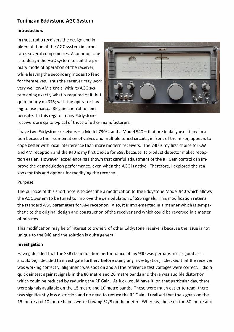
Tuning an Eddystone AGC System Introducon. In most radio receivers the design and im- plementaon of the AGC system incorpo- rates several compromises. A common one is to design the AGC system to suit the pri- mary mode of operaon of the receiver, while leaving the secondary modes to fend for themselves. Thus the receiver may work very well on AM signals, with its AGC sys- tem doing exactly what is required of it, but quite poorly on SSB; with the operator hav- ing to use manual RF gain control to com- pensate. In this regard, many Eddystone receivers are quite typical of those of other manufacturers. I have two Eddystone receivers – a Model 730/4 and a Model 940 – that are in daily use at my loca- on because their combinaon of valves and mulple tuned circuits, in front of the mixer, appears to cope beer with local interference than more modern receivers. The 730 is my first choice for CW and AM recepon and the 940 is my first choice for SSB, because its product detector makes recep- on easier. However, experience has shown that careful adjustment of the RF Gain control can im- prove the demodulaon performance, even when the AGC is acve. Therefore, I explored the rea- sons for this and opons for modifying the receiver. Purpose The purpose of this short note is to describe a modificaon to the Eddystone Model 940 which allows the AGC system to be tuned to improve the demodulaon of SSB signals. This modificaon retains the standard AGC parameters for AM recepon. Also, it is implemented in a manner which is sympa- thec to the original design and construcon of the receiver and which could be reversed in a maer of minutes. This modificaon may be of interest to owners of other Eddystone receivers because the issue is not unique to the 940 and the soluon is quite general. Invesgaon Having decided that the SSB demodulaon performance of my 940 was perhaps not as good as it should be, I decided to invesgate further. Before doing any invesgaon, I checked that the receiver was working correctly; alignment was spot on and all the reference test voltages were correct. I did a quick air test against signals in the 80 metre and 20 metre bands and there was audible distoron which could be reduced by reducing the RF Gain. As luck would have it, on that parcular day, there were signals available on the 15 metre and 10 metre bands. These were much easier to read; there was significantly less distoron and no need to reduce the RF Gain. I realised that the signals on the 15 metre and 10 metre bands were showing S2/3 on the meter. Whereas, those on the 80 metre and
Transcript of Tuning an Eddystone AGC System
Tuning an Eddystone AGC System
Introduction.
In most radio receivers the design and im-
plementation of the AGC system incorpo-
rates several compromises. A common one
is to design the AGC system to suit the pri-
mary mode of operation of the receiver,
while leaving the secondary modes to fend
for themselves. Thus the receiver may work
very well on AM signals, with its AGC sys-
tem doing exactly what is required of it, but
quite poorly on SSB; with the operator hav-
ing to use manual RF gain control to com-
pensate. In this regard, many Eddystone
receivers are quite typical of those of other manufacturers.
I have two Eddystone receivers – a Model 730/4 and a Model 940 – that are in daily use at my loca-
tion because their combination of valves and multiple tuned circuits, in front of the mixer, appears to
cope better with local interference than more modern receivers. The 730 is my first choice for CW
and AM reception and the 940 is my first choice for SSB, because its product detector makes recep-
tion easier. However, experience has shown that careful adjustment of the RF Gain control can im-
prove the demodulation performance, even when the AGC is active. Therefore, I explored the rea-
sons for this and options for modifying the receiver.
Purpose
The purpose of this short note is to describe a modification to the Eddystone Model 940 which allows
the AGC system to be tuned to improve the demodulation of SSB signals. This modification retains
the standard AGC parameters for AM reception. Also, it is implemented in a manner which is sympa-
thetic to the original design and construction of the receiver and which could be reversed in a matter
of minutes.
This modification may be of interest to owners of other Eddystone receivers because the issue is not
unique to the 940 and the solution is quite general.
Investigation
Having decided that the SSB demodulation performance of my 940 was perhaps not as good as it
should be, I decided to investigate further. Before doing any investigation, I checked that the receiver
was working correctly; alignment was spot on and all the reference test voltages were correct. I did a
quick air test against signals in the 80 metre and 20 metre bands and there was audible distortion
which could be reduced by reducing the RF Gain. As luck would have it, on that particular day, there
were signals available on the 15 metre and 10 metre bands. These were much easier to read; there
was significantly less distortion and no need to reduce the RF Gain. I realised that the signals on the
15 metre and 10 metre bands were showing S2/3 on the meter. Whereas, those on the 80 metre and

20 metre bands were showing S4/6; they need to, in order to be above the local noise floor. As soon as
the appropriate test gear was deployed, the problem became clear; the standard AGC system – at least
on my particular 940 – was setting the input to the product detector at too high a level and overloading
it.
While making these measurements, I realised that C91 in my receiver was 4 pF not the 6 pF that is
shown in the circuit diagram/parts list. It looked original and there were no signs that it had ever been
changed. Therefore, I conducted some more listening tests with values of C91 from 2.2 pF to 10 pF.
The results were clear; values in the 2.2 to 3.3 range worked much better than those in the 5.6 to 10
range. C91 forms the top half of a potential divider; consequently, reducing its value reduces the input
to the product detector. Thus, it looks as if Eddystone or an early operator of my particular 940 were
aware of the issue and had reduced C91 to improve the situation.
Design Aim.
Armed with the information gained from the tests and measurements outlined above, I decided to
modify my 940. There were three components to the design aim:
to retain the standard AGC system – that is the circuit and its operating parameters – for
use when demodulating AM signals.
to provide a modified version of the AGC system for use when demodulating SSB signals
to retain the ability to turn Off the AGC system and rely on manual gain control
Plus, of course, any modification had to be easily reversible and not look out of place.
Description of Modification
This modification is quite simple to implement because it makes use of the existing Eddystone circuit
and employs only a multi-pole switch to change component values. There is even an insulted stand-off
in the 940, just where one is needed. The only mechanical work involves swapping a front panel toggle
switch for a 3-pole, 4-way rotary switch.
The description which follows refers to the published Eddystone circuit diagram for the Model 940
downloaded from the Eddystone Users Group website.
The first step is to remove the AGC toggle switch – S4 – from the front panel; retaining the standard
connecting wires for attachment to the new rotary switch.
The second step is to fit a 3-pole, 4-way rotary switch in the front-panel hole vacated by the toggle
switch. This is a little bit of a fiddle because the hole is not the correct size, but my spares box yielded
the necessary nuts and bushes to make it work. Also, it yielded a very nice switch – NSN 5930-99-051-
0462 – which looks in keeping with the rest of the receiver.
The third step is to wire up the new rotary switch.
The rotary switch has four positions, these are:
AGC Off
AM – when the AGC operates as standard; with the same attack and decay times that Eddy-
stone employed and the same 45 Volt delay voltage on the cathode of V7B
SSB Fast – when the AGC system operates in its new ‘tuned’ manner, with the faster of two

decay times
SSB Slow – when the AGC system operates in its new ‘tuned’ manner, with the slower of two
decay times
The first pole of the new switch is wired so as to replace the standard toggle switch – S4. That is to say,
it shorts the AGC line to ground in Position 1; otherwise, it does nothing. The second pole of the switch
is used to provide much longer AGC decay times for SSB reception. It does this by switching an addi-
tional capacitor of 2.2 μF in parallel with C81 when the switch is in Position 3 and an additional capaci-
tor of 4.7 μF in parallel with C81 when the switch is in Position 4. I tried various values from 1.0 to 10
μF before settling on 2.2 and 4.7 as my preferred values. The third pole adds a new 220 kΩ resistor in
series with R44 when the switch is in Position 3 and Position 4; otherwise this pole does nothing. This
reduces the delay voltage to 20 Volts and causes the AGC system to start to reduce receiver gain at -90
dBm instead of -80 dBm (at the antenna input).
Finally, C91 was reduced from 6 pF to 2.2 pF - this reduces the input to the product detector at all input
signal levels.
As an optional extra, R41 was changed from 470 kΩ to 100 kΩ, because I think I prefer the slightly faster
AGC shorter attack time that this yields.
A circuit diagram of these connections/modifications is given below.

Impact of the Modifications.
Clearly, there is a visual impact on the front panel of any Model 940 modified in this way. However, this
can be minimised and done sympathetically - by using a standard Eddystone knob on the new rotary
switch - so that there would be no evidence were the modification to be removed at a future date.
In performance terms, the receiver operates as standard when the new AGC control switch is in the Off
and AM positions. In the two SSB positions, the AGC system starts to act earlier and reduces the steady-
state level of the IF input to the product detector by 5 dBs to 7 dBs over the range of receiver RF inputs
from -80 dBm upwards. This is in addition to the reduction brought about by changing C91 to 2.2 pF.
I have been using the receiver in its modified form for the past three weeks and I will not be changing
back any time soon. It is much easier to operate – on SSB – and the quality of the recovered audio is no-
ticeably better. At my location and with my antenna system, the RF Gain can be left on maximum, when
receiving SSB, and the modified AGC system handles the full range of signals. The input presented to the
product detector is about 10 dBs less than standard; right in the sweet spot where it works well and pro-
duces little distortion. The longer decay times make a big difference as well; it may not be a proper audio-
derived AGC system but, for most brief amateur transmissions, it is a good second best.
Victor Jenkins