The ‘Best Receiver Eddystone Ever Built’? - Ponderings …eddystoneusergroup.org.uk/Tech...
34
1 The ‘Best Receiver Eddystone Ever Built’? - Ponderings on the Eddystone EC958 ‘High-Stability Receiver’ - by Gerry O’Hara, G8GUH/VE7GUH Introduction Some of the best things in life come your way by accident rather than by design. Being a keen admirer of Eddystone receivers for some considerable time, albeit with many years in the wilderness, I often wondered what was the best receiver Eddystone ever made? On joining the ‘old’ EUG (just before its demise) Graeme Wormald sent me the Quick Reference Guide (QRG) which I must say Graeme, is a font of knowledge – mine is getting well worn even after this short time! While reading through this, and perusing the various copies of ‘Lighthouse’ and the earlier ‘Newsletter’, I found quotes that in some folks opinion at least, the EC958 series was possibly ‘the best receiver Eddystone had ever built’, while the S.830 series was noted as being ‘the Jewel in the Crown’. Hmmm… how could this be? Ok, one of these receivers, the S.830, is a late- model valve set built to a very high specification for its day and solely for ‘professional applications’ (aka well-healed and discerning customers) – this being at the ‘pinnacle’ of valve technology in receiver design. But the EC958? – come on, a relatively early solid- state set designed in the mid/late-1960’s using mid-1960’s semiconductors? What about all those professional HF sets made in the 1980’s and 1990’s? - you know, the 1837, 1838, 1650 and 6100 for example. Surely they must be better than a soup’d-up 1960’s ‘tranny’? Even though I am really a valve guy at heart I thought one day I must have access to an EC958 and see why someone thought fit to make that accolade… A Fortuitous Find – and thank Heaven for the EUG Forum… So, back in September 2007 ‘lady-luck’ struck by way of a self-admitted ‘lurker’, and namesake, on the EUG Forum who posted this innocent little note (thanks Gerald!): Hi All, I have been a lurker on here for a while and enjoy just reading the mail. I have a very nice example of the EC 958/3 which was delivered to the Canadian government for service at an airport in Quebec many years ago. It is in excellent cosmetic condition and very good operating as well. It is housed in a desktop cabinet and feels as if it is built like a tank. I do have printed manuals as well for it. I have been considering selling it because it see's so very little use here in my shack and I could really use the space. I wonder if anyone on the group might be able to give me some idea of what a fair market value might be for this awesome receiver? Cheers and thanks Gerald VE4ACE Winnipeg, Manitoba, Canada
Transcript of The ‘Best Receiver Eddystone Ever Built’? - Ponderings …eddystoneusergroup.org.uk/Tech...

‘Best Receiver Eddystone Ever Built’? – The EC958 Gerry O’Hara
1
The ‘Best Receiver Eddystone Ever Built’? - Ponderings on the Eddystone EC958 ‘High-Stability Receiver’ - by Gerry O’Hara, G8GUH/VE7GUH Introduction Some of the best things in life come your way by accident rather than by design. Being a keen admirer of Eddystone receivers for some considerable time, albeit with many years in the wilderness, I often wondered what was the best receiver Eddystone ever made? On joining the ‘old’ EUG (just before its demise) Graeme Wormald sent me the Quick Reference Guide (QRG) which I must say Graeme, is a font of knowledge – mine is getting well worn even after this short time! While reading through this, and perusing the various copies of ‘Lighthouse’ and the earlier ‘Newsletter’, I found quotes that in some folks opinion at least, the EC958 series was possibly ‘the best receiver Eddystone had ever built’, while the S.830 series was noted as being ‘the Jewel in the Crown’. Hmmm… how could this be? Ok, one of these receivers, the S.830, is a late-model valve set built to a very high specification for its day and solely for ‘professional applications’ (aka well-healed and discerning customers) – this being at the ‘pinnacle’ of valve technology in receiver design. But the EC958? – come on, a relatively early solid-state set designed in the mid/late-1960’s using mid-1960’s semiconductors? What about all those professional HF sets made in the 1980’s and 1990’s? - you know, the 1837, 1838, 1650 and 6100 for example. Surely they must be better than a soup’d-up 1960’s ‘tranny’? Even though I am really a valve guy at heart I thought one day I must have access to an EC958 and see why someone thought fit to make that accolade… A Fortuitous Find – and thank Heaven for the EUG Forum…
So, back in September 2007 ‘lady-luck’ struck by way of a self-admitted ‘lurker’, and namesake, on the EUG Forum who posted this innocent little note (thanks Gerald!):
Hi All, I have been a lurker on here for a while and enjoy just reading the mail. I have a very nice example of the EC 958/3 which was delivered to the Canadian government for service at an airport in Quebec many years ago. It is in excellent cosmetic condition and very good operating as well. It is housed in a desktop cabinet and feels as if it is built like a tank. I do have printed manuals as well for it. I have been considering selling it because it see's so very little use here in my shack and I could really use the space. I wonder if anyone on the group might be able to give me some idea of what a fair market value might be for this awesome receiver? Cheers and thanks Gerald VE4ACE Winnipeg, Manitoba, Canada

‘Best Receiver Eddystone Ever Built’? – The EC958 Gerry O’Hara
2
I followed-up on this ‘pronto’ (actually 12 minutes) via the forum and later that evening I was corresponding directly with Gerald off-line, finding out more about his EC958/3, checking-out some photos (eg. as shown right, ‘in the thick of it’ in Gerald’s shack!), sensing this was one of the few opportunities I would likely have of obtaining one of these sets on this side of the ‘Pond’ and thus avoid ridiculous shipping charges – I think I had only seen one such set for sale in the previous 2 years over here, somewhere in the US. I found out what the ‘/3’ suffix actually meant and asked many questions of Gerald until I was convinced this set was for me. I liked the 1960’s ‘Mk II’ front panel styling of this particular set, but I was a little concerned at first that the ‘/3’ circuitry was focused on AM and CW modes, with no switchable USB/LSB facility as per its siblings with a 2.4KHz bandpass filter (the ‘/3’ specification having a 150Hz filter instead for CW reception), and that this version always operates in ‘High Stability mode’ above 1.6MHz. So it took a couple of weeks for me to decide and for Gerald and I to agree to a mutually-acceptable deal. The EC958/3 receiver finally arrived here via Greyhound’s delivery service on October 19, 2007 in some of the best packaging I have ever seen – double-boxed, with foam and custom-trimmed polystyrene sheets, weighing in at around 50lbs. It was actually delivered to my company’s lab and caused quite a few comments from the technicians on how unwrapping it was like a giant ‘pass the parcel’ game. Many thanks Gerald! The set was complete with its original manual and a well-made homebrew wooden plinth speaker and looked even better ‘in the flesh’ than on the many photos Gerald had sent me. What a beauty! – love at first sight… The ‘EC958 Family’ – One for the Album!
Graeme Wormald’s ‘QRG” introduces the EC958 series thus:
‘A very large and successful range. The EC958 was the company’s first high stability solid state receiver and was by far the most complicated set undertaken by that time (late-‘60’s). It was designed by Don Ford, a brilliant Stratton engineer who sadly died young.

‘Best Receiver Eddystone Ever Built’? – The EC958 Gerry O’Hara
3
The mechanical tuning system was more complicated than a clock and had over 100 parts. All models had a fully-tuned front end turret with interpolation frequency setting (ie. two knobs, one for course, the other for fine). It could be re-set within a few Hz then locked. A triple superhet, it covered 10KHz – 30 MHz in 10 bands. It is considered by some aficionados to be the finest set the company ever built. [my emphasis]
The various models ran from 1969 to 1984. During this period the prices started at £7501 and finished at around £6,000 (EC958/12). It was an era of high inflation. Specific models may be rare, but a little patience will locate one version or another…’
The QRG lists 9 variants but notes that there are likely others ‘out there’ – Eddystone have a reputation of making modifications for anyone who would pay for them. Some were very minor, such as changes to the socket types or even the badge, others, such as in the case of sets made for export to Canada, eg. the S.830/4 and EC958/3, were more far-reaching. The EC958 (no suffix) is identified as the ‘basic model’ which ran from 1969 to 1973 along with the EC958/1 (special SSB filter), EC958/2 (special CW filter),
EC958/3 (‘Canadian specifications’ – more on this later), EC958/4 (military specifications), EC958/5 (marine version badged as the Marconi ‘ Nebula’), EC958/D (badged as ‘Debeg’, Germany), EC958/H (badged as ‘Hagenuk’, Germany), EC958/7E (new model introduced in 1973 with digital readout, also badged as the Marconi H2311) and EC958/12 (with added independent sideband facility).
High Stability Techniques
The QRG notes that the EC958 was Eddystones first attempt at a solid state ‘high-stability’ receiver. However, it was not the firms first high-stability receiver – this title goes back to development work at the Bath Tub in the 1950’s, culminating in the S.880 in 1959, followed by the S.880/2 (1962), S.880/3 (1964) and S.880/4 (1966). Check out ‘A Short History of Receiver Development From 1965 to 1995’ (Parts 1 and 2) 1 Coincidentally this was equivalent to an entire annual grant in my first year at Sheffield University in the early 1970’s. If only I had known, I could have sobered-up, quit my girlfriend, sold my Triumph Herald, lived on the streets, starved to death and bought a Bath Tub fresh EC958…

‘Best Receiver Eddystone Ever Built’? – The EC958 Gerry O’Hara
4
by Roger Sutton (‘Lighthouse’, Issues 62 and 63).
So, what is a ‘high-stability’ receiver? Why would this be a requirement of a receiver specification over and above that normally expected of an HF receiver? And what technologies can produce a very high level of
oscillator stability? Good questions, and I am sure a book could be written answering them! – for the purposes of this short article I will just scratch the surface…
The easiest way to make a stable oscillator is to use a crystal as the frequency-determining component. Although still subject to frequency drift with temperature changes of the crystal element, the stability of a well-designed crystal oscillator is an order of
magnitude or so better than a well-designed, so-called ‘free-running’ oscillator (usually termed a variable frequency oscillator or ‘VFO’), ie. one that does not
incorporate a crystal as its frequency-determining element. Of course using a crystal in an oscillator is rather limiting unless you are interested in only one (or a few) frequencies or their harmonics. Even given that a crystal can be made to
oscillate slightly off-frequency by varying its operating conditions, eg. loading with a variable capacitor, tuning across a wide range of even spot frequencies would be impractical. Ok, so what if we focus on improving a free-running oscillator, eg. by using rigid mechanical construction, selection of one of the more stable oscillator types (eg. Hartley, Colpitts or Vackar) and apply good design/construction practices - see sidebar, right. At HF these techniques can certainly reduce drift
Above: the Hartley oscillator. Below: the Colpitts oscillator
Oscillator ‘101’ Every oscillator has at least one active device (valve, transistor, FET or IC) acting as an amplifier. This device is arranged in a circuit such that a portion of its (amplified) output is fed back to its input in the correct phase such that this signal gets amplified and thus a sustained oscillation occurs. The frequency of the oscillation is determined by tuned circuit elements, eg. a crystal, or capacitors and inductors. Frequency or phase stability of an oscillator is usually thought of in the long-term case – measured over minutes, hours, days through years… Of interest here are effects of component changes with ambient conditions, eg. temperature, humidity, mechanical stability and, over longer periods, component aging. Short-term stability is also of interest and the higher the ‘Q’ of the tuned circuit element, the higher the stability of the oscillator and the greater its ability to filter out undesirable harmonics and noise (which is amplified along with the desired oscillator signal frequency). Frequency drift can be minimized by: - Isolating the oscillator by using a buffer
stage - Careful choice of oscillator circuit - Ensuring mechanical stability - Maintaining constant ambient
temperature/humidity - Providing a clean, well-regulated power
supply - Minimizing circuit changes by selecting
appropriate and high-quality components, eg. silver mica or polystyrene capacitors
- Using low-loss, high-‘Q’ coil construction
- Using NPO ceramic ‘drift-cancelling’ capacitors to compensate for temperature changes
- Selection of a low-noise active device and operate it at a low power level
- Use of a low LC ratio: maximise reactive energy

‘Best Receiver Eddystone Ever Built’? – The EC958 Gerry O’Hara
5
to very acceptable levels <200Hz per hour or so – and certainly more than adequate for AM, SSB and even CW reception using very narrow IF filters. But what if you need to keep to within a few Hz using very narrow bandwidths? - or be able to reliably return to exactly the same frequency time after time? - these are the requirements of many surveillance applications, the military, or where systems such as ‘piccolo’ were in use to ensure confidentiality of diplomatic traffic. To obtain such stability and reproducibility of received frequency more sophisticated techniques are needed.
Below and right: the ‘famous’ Barlow-Wadley XCR30. At $225 new in the early-1970’s these were no ‘cheap trannie’! – today, these very collectable sets fetch around $1,000 on EBay. Note the MHz (left) and KHz (right) tuning scales on the enlargement below. Here, the radio is tuned to 10.750MHz.
‘Best Receiver Eddystone Ever Built’? – The EC958 Gerry O’Hara
6
One early technique aimed at achieving enhanced stability was to use a stable high-frequency crystal-controlled oscillator heterodyned with a reasonably stable VFO in a single conversion receiver design. This technique can achieve high stability, but only over a fairly small tuning range of up to 1MHz. Some 28 or more crystals would be needed to cover the entire HF band (2MHz - 30MHz) – perhaps not that practical. Another technique developed was to use a double-conversion approach, with the first local oscillator (LO) being crystal-controlled and the second using a VFO tuned over a relatively small range (VFO’s designed to operate over a small frequency range and at low frequencies can be made relatively stable). Such an approach was adopted by Eddystone in the S.880-series of valve receivers and later in the EA12 and S.830-series (sort-of). The S.880 models used only 10 crystals to cover the entire 0.5MHz to 30.5MHz by using lower and upper mixer frequencies on alternate 1MHz bands and by multiplying the crystal fundamental up to 3 times, with a tunable IF (VFO) covering the range 2.5MHz to 3.5Mhz (block diagram shown at top of page and the receivers innards in the photo, above). The EA12, covering only the (then) six HF amateur bands in 600KHz ranges: 160, 80, 40, 20, 15 and 10 metres, the latter being covered in 4x 600kHz ranges. This design used 9 crystals in the first LO stage with the second LO tuning from

‘Best Receiver Eddystone Ever Built’? – The EC958 Gerry O’Hara
7
1.1MHz to 1.7MHz. The S.830-series utilized VFO’s for both first and second LO operation, the former being the main tuning control and the latter being for incremental tuning (the first IF tuning from 1.25MHz to 1.45MHz, the second IF fixed at 100KHz). Whilst in this configuration this receiver could not be considered to be true ‘high stability’, it was a very stable design, due mainly to careful electrical and mechanical design, coupled with quality construction. However, in addition, this model had a facility
to switch up to 8 crystals into circuit instead of the first VFO, thus effectively becoming a quasi-high stability design similar in concept to the S.880-series and EA12 (perhaps it could be an ‘S.880 ‘light’?).
Another fairly early concept capable of achieving high stability was the ‘Wadley Loop’, developed in the post WWII years by Dr. Trevor Wadley (1920-1981). Wadley was a
Block Diagram and Circuit Description of the Barlow-Wadley XRC-30

‘Best Receiver Eddystone Ever Built’? – The EC958 Gerry O’Hara
8
South African Engineer who had worked during WWII for the Telecommunications Research Establishment in England. Working later for RACAL in the UK, Wadley designed the famous RA17 and RA117 communications receivers in the mid-1950’s which was the first to use this technique2. These receivers were supplied to the Royal Navy and later to other military and surveilance outfits. The Wadley Loop was subsequently incorporated into several solid-state receivers, including the famous Barlow-Wadley XCR-30 in the early 1970’s (see illustrations on Page 6). The XCR-30 was the first transistor portable claimed to achieve a tuning accuracy of 5KHZ over the 0.5-30 MHz spectrum and was actually a fairly simple 18 bipolar transistor design (14 transistor plus one audio IC in later models), without the optional FM adapter. The circuit description and block diagram are provided on the previous page. In this set, one knob was used to choose one of thirty 1MHz bands, with the second knob tuning within the selected 1MHz band, these being displayed on adjacent rotating dials. The XCR-30 was followed by the Yaesu FRG-7 and FRG-7000, and by several less famous/popular sets, including the Drake SSR-1, Realistic DX-300 and the Standard C6500 (see Page 31).
The basic Wadley Loop principle is shown in the figure below. The values are those of the Yaesu FRG-7, but the principle is essentially the same for other receivers using this technique (the LO and IF frequencies may change from design to design).
In the FRG-7 design, the coarse tuning is achieved via a VFO covering the 30MHz range from 55.5MHz to 84.5MHz without bandswitching. The VFO output is sent to Mixer 1 of the receiver and to balanced Mixer 2. Mixer 2 combines the VFO signal with the output of a 1MHz harmonic generator (produced by a very stable crystal oscillator).
2 Now, it so-happens that I have a RACAL RA117 spread all over my workshop at the moment. It is quite a sight – but I fear not for sore eyes. This particular set is one of five the SPARC museum in Coquitlam BC acquired over the years, this particular one being one of three donated to the museum one Sunday afternoon. The museum decided to retain the two best-condition receivers out of the five, and sell the other three to members of SPARC. The deal was that those buying would also have to restore the two sets being retained by the museum. My set is in a particularly dilapidated state and I suspect that I will end up virtually rebuilding it – all new capacitors and resistors - months of work… Check out the article on restoring an RA-117 by Peter Holtham in a recent Radio Bygones (Issue 114, August/September, 2008).

‘Best Receiver Eddystone Ever Built’? – The EC958 Gerry O’Hara
9
Of the multitude of harmonics produced, only the one giving a mixing product close to 52.5 MHz is amplified. The amplified signal is then sent to Mixer 3, where it is combined with the output of the IF amplifier to produce a signal in the 2 to 3 MHz range. This signal is then tuned in a 2 to 3 MHz receiver (tunable IF) where it is converted to a standard 455KHz IF. As a result of this process, all the Wadley Loop receivers are inherently triple-conversion designs. So, why is it called a ‘drift cancelling loop’? Suppose we want to tune a signal at 5.05MHZ. Then the MHz knob has to be set to ‘5.0MHz’ and the KHz knob to ‘50KHz’. With these settings, the VFO will produce a 60.5MHz signal (55.5 + 5) from which, by subtraction, a 55.45MHz signal is delivered to the (first) IF amplifier. Notice that the VFO frequency is added and the signal frequency is subtracted. The balanced Mixer 2 combines the 60.5MHz with the 8th harmonic of the 1MHz crystal oscillator (8MHz) and, by subtraction, produces a 52.5MHz signal. The VFO frequency is then again added. Finally the 52.5MHz signal is subtracted from the 55.45MHz signal from the (first) IF amplifier, producing a 2.95MHz signal which is tuned in the last (2 to 3MHz tunable IF) section of the receiver. So, the 2.95MHz signal is the result of an operation where the VFO frequency is first added and then subtracted from the input signal's frequency. This is the trick to achieve drift cancellation.
To illustrate this, suppose that the VFO is not exactly at 60.5MHz, or that it drifts 150KHz upwards, and goes to 60.65MHz. The (first) IF signal is now at 55.60MHz, still within the first IF bandpass (the bandwidth of the first IF is carefully set to allow a desired range of frequencies through). The balanced mixer now produces a 52.65MHz output, also within the amplifier bandpass (notice that if the drift is excessive, the signal will fall outside the bandpass, activating the lock indicator light). The result of this is that the output signal is still 2.95MHz (55.60-52.65). So, despite the VFO drifting 150KHz upwards (that’s pretty poor by any standards!) the output frequency did not change, ie.
the drift was cancelled.
In the RACAL RA17, block-diagram, left, the Wadley Loop system again uses a single 1MHz crystal to generate a ‘comb’ of harmonics at 1MHz intervals and a mixing process with a tuneable 45.5MHz to 75.5MHz
‘Best Receiver Eddystone Ever Built’? – The EC958 Gerry O’Hara
10
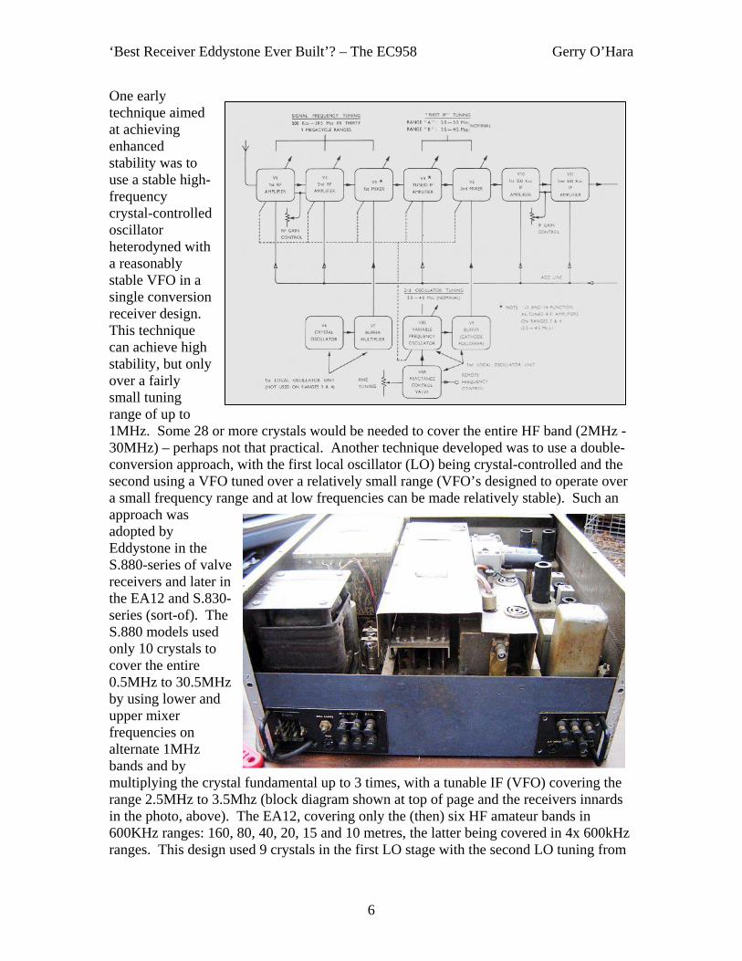
oscillator providing 30 tuneable ranges from 500KHz to 30MHz. The outputs of the first mixer (42.5MHz) and second mixer (45MHz) are amplified and then fed to the third mixer. With the 45MHz IF amplifier having a flat bandpass range of 1MHz, the output of the third mixer is 2.5MHz +/- 500KHz. This 2MHz to 3MHz IF signal is then amplified and tuned with a 2.455MHz to 3.455MHz mixer/oscillator, passing through a 455KHz IF to the AM and SSB detectors.
To summarise, the main advantages of the Wadley Loop principal are:
- Continuous frequency coverage, eg. from 1MHz to 30Mhz - Constant tuning rate - Good bandspread (eg. 1MHz per traverse of the dial) - High level of frequency stability (in the order of <10Hz/hour) - Good repeatability due to electronic rather than mechanical band
switching
Given a high-grade tuning mechanism and dial on the tunable IF, eg. the RA17/RA117 models use a 35mm film scale some 145 feet long which has only to cover a range of 1MHz (photo, right), the frequency of the received signal may be read off and re-set very accurately. This is a very good feature where it is necessary to pre-set the receiver in readiness for an expected signal, as for many professional applications.
The main disadvantage of the Wadley Loop is the need for a triple-conversion receiver topology which is implicit in its design: multiple-conversion receivers are prone to overload and cross-modulation effects in the presence of strong signals, as well as excessive mixer noise as they violate the principle that the main selectivity elements in a receiver should immediately follow the mixer. However, these effects can be reduced by careful design, for example using balanced mixers and special transistors or valves, but can never be entirely eliminated. Also, a price must be paid for all the advantages which
‘Best Receiver Eddystone Ever Built’? – The EC958 Gerry O’Hara
11
this system provides: efficient low-pass and band-pass filters are required, in order to obtain correct operation and considerable care must be taken to shield various sections from each other to prevent the harmonics from the 1MHz crystal oscillator from being injected and received as incoming signals. Power supplies must be stabilized and their connections to the various circuits must be well-filtered. Very careful mechanical layout is needed, including the use of screened compartments for the various oscillators and filters. All this effort cost money.
Phase-locked loops/frequency synthesizers were the next techniques to be developed for obtaining high-stability, these having stability figures similar to (or better than) a quartz crystal oscillator. A single-conversion or dual-conversion receiver using a phase-locked synthesizer is, in principle, the best approach and this is the reason why the Wadley Loop eventually disappeared from use. On the other hand, with the Wadley Loop the noise problems that affect receivers with poorly-designed/constructed (aka cheap) synthesizers are not present, and this is a redeeming quality of this technique.
Trannies v Valves – Which is best for Stability? Early semiconductor devices suffered from a variety of issues when used in receiver front-ends when compared with their contemporaneous valve counterparts: higher noise, much more easily overloaded/susceptible to cross-modulation/blocking and could be damaged due to local transmitters or static discharges. Newer devices and improved circuit techniques gradually mitigated many of these shortcomings. In oscillator applications, their lower energy dissipation helped in developing stable oscillators, however, this benefit was only fully realized if they were incorporated into carefully designed circuits coupled with solid mechanical construction techniques. Even so, true ‘high-stability’ at HF still needs to utilize the techniques described above. One big advantage that semiconductors have though is being able to incorporate complex circuitry in a relatively small space and at lower cost than a valve-based equivalent, eg. compare the size and weight of the (discrete semiconductor) Barlow Wadley with the (valve) RA17... not really a fair comparison I know, but it illustrates my point. The EC958-series was the first to incorporate such relatively-sophisticated techniques in the solid state Eddystone receiver range (ok, so it took me 11 pages to get there – I bet you were getting your hopes up when you saw a photo of an EC958 on page 2 eh?). Overview of the EC958/3 Features and Circuit The basic EC958 sported 41 transistors, 46 diodes and 12 integrated circuits. The 1973 model EC958/7E with its digital readout sported 48 transistors, 53 diodes and 42 integrated circuits and the ‘ultimate’ EC958/12 model, with its independent sideband facility, had a whopping 75 transistors, 99 diodes and 70 integrated circuits! The EC958 operates as a single, double or triple-conversion superhet, depending on the actual tuning range in use – bit of a clue there: the Wadley Loop is not used all the time

‘Best Receiver Eddystone Ever Built’? – The EC958 Gerry O’Hara
12
(not much point for the lower frequencies, where quality VFO design/construction affords adequate frequency stability). A total of 10 ranges cover 10KHz to 30MHz thus: Range Coverage Conversion IF1 IF2 IF3 1 20 to 30MHz Triple Tunable 1235-
1335KHz 250KHz 100KHz
2 10 to 20 MHz Triple Tunable 1235-1335KHz
250KHz 100KHz
3 4 to 10MHz Triple Tunable 1235-1335KHz
250KHz 100KHz
4 1.6 to 4MHz Triple Tunable 1235-1335KHz
250KHz 100KHz
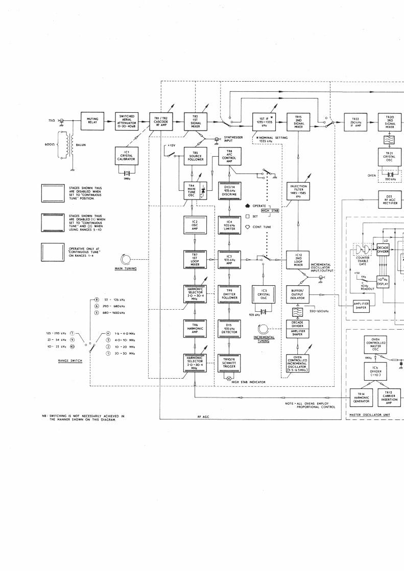
5 680 to 1650KHz Double 250KHz 100KHz - 6 290 to 680KHz Double 250KHz 100KHz - 7 125 to 295KHz Single 100KHz - - 8 53 to 126KHz Double 250KHz 100KHz - 9 23 to 54KHz Single 100KHz - - 10 10 to 23KHz Single 100KHz - - Availability of the tunable IF on the four highest frequency ranges provides an incremental tuning facility that is absent on the other ranges. The incremental tuning control covers 100KHz, directly readable to within 200Hz. Provision is made on the four upper frequency ranges to operate the receiver in ‘high-stability’ mode. In this configuration, the 1st LO drives a drift-canceling loop (you got it, the ‘Wadley Loop’ – see, I knew those 11 pages weren’t wasted…), locked to harmonics from an oven-controlled 1MHz master oscillator. Tuning is carried out with the ‘Incremental Tuning’ control after setting the ‘Main Tune’ control to the 0.1MHz calibration point at the low edge of the 100KHz segment in which the required signal frequency lies. A crystal calibrator is provided to permit accurate settings of the tuning scales. A full description of the circuit is included in the very comprehensive manuals, downloadable from the EUG site (the block diagram page is reproduced as an attachment to this article for easy reference), and is briefly summarized below. It should be noted that the EC958/7E model (and later versions), introduced in the early 1970’s incorporated significant improvements to the circuit, enhancing the receivers stability as well as providing digital frequency display (details can be found in ‘Improved General Purpose Communications Receiver’ by CJ Mellor and RT Sutton, 1974).
RF Amplifier/1st Mixer An n-channel junction FET and an n-channel single-gate MOSFET are deployed in a ‘cascode’ configuration as the RF amplifier stage, preceded by a switched attenuator, protection diodes and muting relay. A dual-gate n-channel MOSFET is used in the 1st mixer stage with signal input to gate 1 and local oscillator injection to gate 2. All signal-frequency circuits are gang-tuned by the main tuning control.

‘Best Receiver Eddystone Ever Built’? – The EC958 Gerry O’Hara
13
1st Local Oscillator A single-gate MOSFET is used in a tuned-gate oscillator configuration, tuned by a further section of the main tuning gang. A source-follower is used to buffer the oscillator from the mixer stage. A varicap diode forms part of the tuned circuit, this being used in the ‘high-stability’ mode (see later). 1MHz Crystal Calibrator The crystal calibrator deploys a linear integrated circuit (IC), the output of which couples into the RF section via a small probe close to the RF amplifier stage. It provides 1MHz markers across the bands and a mechanical adjustment to the scale graticule can be made to accommodate minor scale non-linearity. 10KHz markers are provided across ranges 5 to 10 in the EC958/3 version. Tunable IF This section of the receiver circuitry only operates in ranges 1 to 4 (1.6MHZ to 30MHz). It includes the 2nd mixer (dual-gate MOSFET), 2nd loop-mixer (an IC, part of the drift cancelling loop), incremental oscillator (550KHz to 650KHz), deploying an FET and two bipolar devices as emitter-followers, and an IC as the 935KHz crystal oscillator - this being used only in the ‘continuous tune’ mode (this mode is absent in the EC958/3 model). The tunable IF covers the range 1235KHz to 1335KHz and all frequencies in this range are converted to the 250KHz IF in the 2nd mixer. Oscillator injection in the range 1485KHz to 1585KHz is derived from a ‘pre-mixing’ technique which combines the output of the incremental oscillator with the 935KHz crystal oscillator – this technique allows the incremental oscillator to run at a third of the required injection frequency, contributing to the high stability of this stage. Drift-cancelling Circuitry (the ‘Wadley Loop’) This circuitry is used only when the receiver is operating in high-stability mode on the HF ranges (1 to 4). In this mode of operation, the incremental oscillator provides 550KHZ to 650KHz drive to the 2nd loop mixer. However, the 935KHz drive is now derived from the first loop mixer, with the 935KHz crystal oscillator disabled. Output from the first loop mixer is derived from heterodyning the main tune oscillator with the appropriate harmonic derived from the 1MHz-based master oscillator (sound familiar, per the RACAL and Barlow Wadley? – different frequencies and hardware, but same principle). The resultant harmonic will be a multiple of 100KHz and is selected to lie 400KHz higher than the chosen 100KHz calibration point to which the main tuning control is set.

‘Best Receiver Eddystone Ever Built’? – The EC958 Gerry O’Hara
14
Master Oscillator and Harmonic Amplifier
This master oscillator is a 1MHz, oven-controlled crystal oscillator housed in a double-screened box to minimize radiation. This unit provides two independent outputs via emitter-follower stages: one at 100KHz to provide carrier insertion for CW/SSB, the second comprising a ‘comb’ of 100KHZ ‘spikes’ up to at least 30.4MHz, derived from an IC decade divider. The output is fed to a harmonic amplifier stage, tuned in the range 2.0MHz to 30.4MHz by the main tuning gang, thus selecting the desired 100KHz harmonic. 1st Loop Mixer and Oscillator Amplifier A dual-gate MOSFET is deployed as the 1st loop mixer. Here, the selected 100KHz harmonic is applied to gate 1, with gate 2 being fed from the main tune oscillator via a wideband (IC) amplifier. The difference between the two frequencies appears on the drain of the MOSFET, which is tuned to 935KHz (note: output is only at discrete 100KHz settings of the main tune control). 935KHz Loop Stages Output from the 1st loop mixer is coupled to a double-tuned bandpass filter at 935KHz, feeding an IC loop amplifier stage, its output being fed via an emitter-follower to a second 935KHz double-tuned bandpass filter. A detector and Schmitt Trigger circuit drives a relay that operates the ‘High Stab’ indicator light when 935KHz drive is available, confirming correct setting of the main tune control for high-stability operation. An additional 935KHz filter provides output to the 2nd loop mixer. Also, the circuit provides a 935KHz signal to the AFC discriminator and control amplifier, the off-tune voltage of which is applied to the varicap diode in the main tune oscillator circuit (noted above) to mitigate drift. 250KHz and 100KHz IFs The 250KHz IF operates on all ranges except 7, 9 and 10. The input is derived from either the 1st or 2nd mixer, depending on which range is in use: for ranges 1 to 4, ie. when the tunable IF is in use, input is taken from the drain of the 2nd mixer stage; whereas on ranges 5, 6 and 8, the drain of the 1st mixer stage. Selectivity at 250Khz is provided by an 11-element ceramic ladder filter, feeding gate 1 of the 3rd mixer stage dual-gate MOSFET via a single bipolar amplifier. The associated local oscillator comprises an IC and discrete amplifier stage, injecting either 150KHz or 350KHz, depending on the selected sideband. Output from the oscillator amplifier is fed to gate 2 of the 3rd mixer. The 100KHz IF output is developed at the drain of the 3rd mixer stage. The 100KHz IF comprises an L/C filter with four switchable bandwidths (400Hz, 1.3KHz, 3KHz and 8KHz), a multi-pole crystal filter for SSB, four cascaded FET amplifier stages and two independent AGC circuits. An emitter-follower provides
‘Best Receiver Eddystone Ever Built’? – The EC958 Gerry O’Hara
15
drive for separate AM (diode) and CW/SSB detectors. In the EC958/3, the SSB filter is replaced with a narrow-band CW filter with a bandwidth of 150Hz. AGC Systems Separate AGC lines are available for control of the RF amplifier stage and the first three 100KHz IF stages. The RF AGC is derived from the final 100KHz filter, whereas the IF AGC is derived from the final IF amplifier stage. A rapid discharge characteristic is available in the AM and CW/SSB modes, with a ‘hang’ characteristic when in SSB mode. CW/SSB Detector and BFO An n-channel dual MOSFET is used as a product detector for CW/SSB reception, with signal input to gate 1 and oscillator injection to gate 2. Output is taken from the drain via a low-pass filter to remove the 100KHz component. Oscillator injection for CW reception is derived from the tunable BFO, and SSB signals can be received using either the tunable BFO or the high-stability 100KHz outlet from the master oscillator unit (the latter facility is not available in the EC958/3 model circuit configuration without modifying the set’s wiring). Also, USB/LSB switching is not available on ranges 7, 9 and 10, when the receiver operates with conversion direct from the signal frequency to the 100KHz IF (it is unlikely that SSB mode transmissions will be found below 300KHz anyway). Audio Circuits Two independent audio amplifier channels are provided with separate gain controls. The AF gain control feeds the High Level audio channel, whereas a pre-set line-level control feeds the Low Level audio channel, this being intended for connection to 600 ohm line circuits. The High Level Channel can feed an internal monitor speaker, external speaker or phones. Conventional bipolar transistor circuitry is used in both amplifiers. Metering and Power Supply The built-in panel meter can be switched to read carrier or line (audio) level, and is operated with centre-zero for use as an FSK tuning monitor (when an optional FSK module is fitted). The receiver can be operated from 100v to 125v, or 200v to 250v AC. Operating voltages are obtained from a high-grade potted transformer with four secondary windings. Two of these windings feed bridge rectifiers and provide zener-stabilized 12v and 15v DC supplies, the others provide low-voltage AC to the indicator lamps and to the master oscillator crystal oven.
‘Best Receiver Eddystone Ever Built’? – The EC958 Gerry O’Hara
16
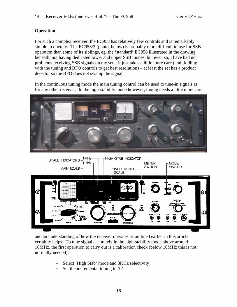
Operation For such a complex receiver, the EC958 has relatively few controls and is remarkably simple to operate. The EC958/3 (photo, below) is probably more difficult to use for SSB operation than some of its siblings, eg, the ‘standard’ EC958 illustrated in the drawing beneath, not having dedicated lower and upper SSB modes, but even so, I have had no problems receiving SSB signals on my set – it just takes a little more care (and fiddling with the tuning and BFO controls to get best resolution) – at least the set has a product detector so the BFO does not swamp the signal. In the continuous tuning mode the main tuning control can be used to tune-in signals as for any other receiver. In the high-stability mode however, tuning needs a little more care
and an understanding of how the receiver operates as outlined earlier in this article certainly helps. To tune signal accurately in the high-stability mode above around 10MHz, the first operation to carry out is a calibration check (below 10MHz this is not normally needed):
- Select ‘High Stab’ mode and 3KHz selectivity - Set the incremental tuning to ‘0’

‘Best Receiver Eddystone Ever Built’? – The EC958 Gerry O’Hara
17
- Tune to the ‘MHz’ calibration point nearest to the required signal frequency
- Press the ‘Cal’ button and adjust the main tuning to locate the marker signal, tuning for zero beat
- Release the ‘Cal’ button and adjust the scale graticule to coincide with the MHz marking on the scale
Next, move the ‘High Stab/Cont Tune’ switch to ‘set’ and
- Adjust the main tuning to the 0.1MHz calibration point at the low-frequency end of the desired 100KHz segment. Tune around this setting until the ‘High Stab’ legend illuminates
- Move the ‘High Stab/Cont Tune’ switch to ‘Operate’. This introduces the automatic frequency control (AFC) system on the first LO
- Use the incremental tune control to tune the desired frequency within the selected range (the tuning rate is sensibly constant at around 2.5KHz per revolution of the tuning knob), adding the incremental (film scale or digital, model dependant) reading to the main scale reading, eg.
Desired signal frequency 20.635MHz Set main tuning control to 20.6MHz Set incremental tuning control to 35KHz
- Adjust the Peak-RF control for maximum signal This all sounds rather complicated and time-consuming, but with a little practice it becomes second nature and is very quick. To change from continuous tuning to the high-stability mode for a signal already tuned-in, the main tune and incremental tuning controls can be manipulated simultaneously to maintain the signal in tune until the main tuning control coincides with the 0.1MHz set point immediately below the signal frequency. Then select ‘High Stab’ mode and tweak the main tune control (if necessary) to illuminate the ‘High Stab’ legend, and then tune the desired signal in accurately using the incremental tuning control. Again, this is much more complicated to describe than to actually do in practice, honest! Tuning the EC958/3 model is somewhat different in operation to the above as this model is always in the high-stability mode on ranges 1 to 4 (1.6MHz to 30MHz). The main tuning control functions in the normal manner on ranges 5 to 10 (10KHz to 1.65MHz), allowing the receiver to be continuously tuned. On these ranges, the incremental tuning control is inoperative and the scale projection is extinguished. On ranges 1 to 4 however, the main tuning control is tuned in steps of 100KHz by reference to the ‘High Stab’ indicator (or, more accurately, by observing the panel meter for centre-zero indication when the tuning is set to a 100KHz step). Interpolation between adjacent 100KHz points is achieved by using the incremental tuning control as described above. SSB reception using the EC958/3 model is achieved by setting the mode to CW, selecting 3KHz selectivity and then offsetting the BFO to either + or – 1.5KHz to suit the transmitted sideband.

‘Best Receiver Eddystone Ever Built’? – The EC958 Gerry O’Hara
18
Construction Details Early models were housed in a wrap-around desk cabinet as per the early-model S.990R VHF receiver (photo, right) introduced a little earlier, and who’s styling reflected the MkII valve set lineage as per the S.840C, S.830-series, S.940, EA12 etc, ie. grey finish, similar knobs and chrome-plated carrying handles. Later models were rack-mounted with an optional desk cabinet - as per the one I own (photo, below), though retaining similar front panel cosmetics. Subsequently (early-1970’s), further cosmetic changes occurred, including a different front panel colour scheme and rectangular-shaped black carrying handles.
The front panel is reasonably ergonomic and ‘looks right’: the band changing and tuning controls can all be handled by the left hand, with the mode, gain, BFO, selectivity and other controls by the right. The frequency display on the early models (such as mine) is less than ideal by modern standards, but is perfectly adequate, allowing resolution to around 100Hz by interpolation between the 200Hz marks on the film scale. The later, digital display versions were a significant improvement. Nevertheless, the older display reminds me of a RACAL RA17/RA117 and in my book at least that is no bad thing (Gordon, please forgive me for saying that…).

‘Best Receiver Eddystone Ever Built’? – The EC958 Gerry O’Hara
19
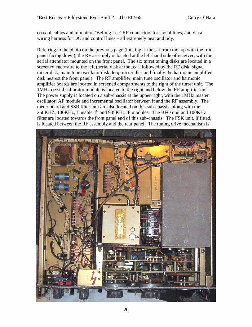
Internally the set is a ‘modular masterpiece’ (photo below) and, I think, is a sight to behold – very impressive. This set has as much mechanical engineering built into it as it has electronics – from the high-quality gearbox/flywheel tuning mechanism to the layout of the chassis and the neat wiring harnesses. One day I will take a peek into the various modules and take photos of the ‘innards’, but not for this overview article. The range switch (turret) is an interesting construction, this being a series of six circular double-sided printed circuit boards (‘discs’) holding the RF tuned circuits. The remaining RF components are mounted on a further six printed circuit boards, these being the crystal calibrator, ‘peak-RF’, the RF amplifier, main-tune oscillator, harmonic amplifier and AFC boards. The remaining circuitry is housed in six fully-screened modules, these being the 935KHz loop amplifier, tunable IF, 250KHz IF, 100KHz IF, audio amplifiers and the optional FSK unit. Other circuit boards hold the meter circuitry and pre-sets, aerial attenuator, master oscillator, incremental oscillator, 100KHZ filter, the CW/SSB detector and BFO. The various boards and modules are connected using
‘Best Receiver Eddystone Ever Built’? – The EC958 Gerry O’Hara
20
coaxial cables and miniature ‘Belling Lee’ RF connectors for signal lines, and via a wiring harness for DC and control lines – all extremely neat and tidy. Referring to the photo on the previous page (looking at the set from the top with the front panel facing down), the RF assembly is located at the left-hand side of receiver, with the aerial attenuator mounted on the front panel. The six turret tuning disks are located in a screened enclosure to the left (aerial disk at the rear, followed by the RF disk, signal mixer disk, main tune oscillator disk, loop mixer disc and finally the harmonic amplifier disk nearest the front panel). The RF amplifier, main tune oscillator and harmonic amplifier boards are located in screened compartments to the right of the turret unit. The 1MHz crystal calibrator module is located to the right and below the RF amplifier unit. The power supply is located on a sub-chassis at the upper-right, with the 1MHz master oscillator, AF module and incremental oscillator between it and the RF assembly. The meter board and SSB filter unit are also located on this sub-chassis, along with the 250KHZ, 100KHz, Tunable 1st and 935KHz IF modules. The BFO unit and 100KHz filter are located towards the front panel end of this sub-chassis. The FSK unit, if fitted, is located between the RF assembly and the rear panel. The tuning drive mechanism is

‘Best Receiver Eddystone Ever Built’? – The EC958 Gerry O’Hara
21
located between the RF unit/incremental oscillator and the front panel. This assembly includes the dial scale projection system. The under-chassis (photo, base of previous page) is reserved mainly for interconnect cables and power distribution, however the ‘peak RF’ board is also located here, adjacent to the RF assembly.
The rear panel varies between models: the EC958/3 (photo, above) includes a ‘chocolate block connector’ for various outputs (of course! - us Canadians love chocolate...) Performance I have not attempted any re-alignment of my set (yet), so the following comments are for the set in its ‘as-received’ condition. Interestingly, my set came with a service record from VE4KR dated May 12, 1999, where it was noted, amongst other things, that the alignment had been checked and was found to be ‘within specs’ – good to know! (even if
it was 9 years ago). I checked the dial calibration and found it to be slightly out on some ranges, but certainly nothing much to be concerned-over (leave well-alone I think). On the bands it compares very well with my S.830/4 and S.940 receivers (photo, right), though it seems slightly more sensitive and definitely more stable.
The filters are very good and the 400Hz and 150Hz settings are very useful for CW. SSB reception is also ok – just need to adjust the BFO when moving from upper to lower sideband: the 3Khz (or even the 1.3KHz) position of the filter works well in this mode.

‘Best Receiver Eddystone Ever Built’? – The EC958 Gerry O’Hara
22
Conclusion My conclusion is that there is probably really no such thing as the ‘best receiver Eddystone ever made’ as what may be considered ‘the best’ is a very subjective thing: Best for CW? Best for SSB? Best for AM? Best for RTTY? Best in the presence of strong signals? Best for weak signal performance? Best for strong adjacent signal performance? Best coverage? Best bandspread? Best for ‘bandcruising? Best frequency stability….. etc, etc. Then there comes the question of whether a decades-old receiver is meeting its original specs or not? – not many of us have the correct (and recently calibrated) test gear and expertise to check this, so instead we rely on comparisons with sets of known performance and other relative checks. Having said all that, I must admit that the EC958 is probably one of the best receivers Eddystone ever made: it has adequate sensitivity, good cross-modulation performance (that RF attenuator helps), has excellent frequency stability, good filters, that smooooth Eddystone tuning (x2!!) and ease of use. On the down-side it seems to be a little noisier than some other receivers I have used, but I have not attempted to make any quantative measurements. All-in-all though, I think this set would be on my Eddystone favourites shortlist… 73’s © Gerry O’Hara, G8GUH/VE7GUH ([email protected]), Vancouver, BC, Canada, November, 2008 Some Further Reading/References on the EC958 Series/High Stability: • ‘The Ultimate Quick Reference Guide’ (QRG) 2nd Ed. Graeme Wormald, 2002 • ‘The Cooke Report’, Bill Cooke, 1998/9 • Manuals for EC958/1, EC958/3 and EC958/7E • Various ‘Data Sheets’ covering several EC958 models • Various ‘Lighthouse’ and “Newsletter’ articles (see Page 23), including • ‘A Short History of Receiver Development From 1965 to 1995’ (Parts 1 and 2), RT
Sutton, 1995 (reprinted in ‘Lighthouse’, Issues 62 and 63) • ‘Improved General Purpose Communications Receiver’, CJ Mellor and RT Sutton,
Point-to-Point Communication Vol. 18 No. 1, 1974 All the above can be downloaded from the EUG website, http://eddystoneusergroup.org.uk/)

‘Best Receiver Eddystone Ever Built’? – The EC958 Gerry O’Hara
23
EUG Newsletter/Lighthouse (from ‘Super Index’) Issue Page advert .................................................................................... 15................18 assessment, School of Signals (1977)............................................ 94.................6 bulbs, query as to voltage ............................................................... 77................20 catalogue extract ............................................................................. 49.................9 comparison, different versions ......................................................... 8.................13 co-ax, coupling, corrosion ............................................................... 26................11 .................................................................................... 27.................2 .................................................................................... 37................11 .................................................................................... 38.................2 eBay .................................................................................... 91................21 faults .................................................................................... 38.................9 .................................................................................... 67................31 featured receiver ............................................................................. 14.................6 Hagenuk & Marconi equivalents...................................................... 79................15 intermittent function ......................................................................... 33................19 Isle of Wight museum...................................................................... 26................19 manuals available............................................................................ 47................30 maritime radio, used by ................................................................... 94.................9 MoD reference numbers.................................................................. 20................12 overhaul .................................................................................... 12................15 .................................................................................... 35.................3 prices .................................................................................... 24................17 restoration (Graham Gosling).......................................................... 88................28 scale cursor query ........................................................................... 57................10 problem cured ....................................................................... 58................18 servicing .................................................................................... 17................13 success of .................................................................................... 44.................5 suffix, query as to ............................................................................ 47................17 tuning ratio arm, setting ................................................................... 56................17 display, fault .......................................................................... 12................13 /H, Hagenuk version......................................................................... 5..................2 /D, Debeg version............................................................................. 5..................2 /1, P.O. acquires 50 sets ................................................................. 85................43 /4, MIMCO H2310 equivalent .......................................................... 54................13 /5 MIMCO Nebula .................................................................... 52................12 manual.................................................................................. 19................11 /7E featured model ...................................................................... 67................17 first with digital readout ......................................................... 46.................6

‘Best Receiver Eddystone Ever Built’? – The EC958 Gerry O’Hara
24
Some Web References and Links: - http://www.chiark.greenend.org.uk/~alanb/ec958.html - http://www.radiomuseum.org/r/eddystone_ec9587ec9587ec_958.html - http://www.radiomuseum.org/r/eddystone_8802s880.html - http://www.recelectronics.demon.co.uk/ra17.htm - http://www.g3ynh.info/Racal/ra17.html - http://freespace.virgin.net/mark.roper/racal_model_ra17_series_of_commu.htm - http://www.eham.net/reviews/detail/6147 - http://www.vmarsmanuals.co.uk/ra117/ra117index.htm - http://ra117.blogspot.com/2007/04/above-is-front-view-of-ra117-receiver.html - http://www.dr-boesch.ch/radio/radio-e/standard-c6500-e.htm - http://www.dxing.com/rx/dx200.htm - http://www.geocities.com/pa2ohh/06ssr1.htm - http://televideo.ws/FRG-7.html - http://www.youtube.com/watch?v=R0pQoMSq4Ak - http://www.qsl.net/vk3jeg/b_wadley.html - http://members.ozemail.com.au/~radio/wadley.html - http://www.barlowwadley.it/ - http://www.lannuier.com/nrd505/historical.html - http://www.geocities.com/pa2ohh/06barlow.htm - http://www.suertenich.com/html/radios/ra17l/racal_RA17L.html - http://www.bookrags.com/wiki/Trevor_Wadley - http://en.wikipedia.org/wiki/Hartley_oscillator - http://www.electronics-tutorials.com/oscillators/hartley-oscillator.htm - http://en.wikipedia.org/wiki/Colpitts_oscillator - http://www.radio-electronics.com/info/receivers/synth_basics/synth_basics.php - http://en.wikipedia.org/wiki/Frequency_synthesiser - http://www.tpub.com/neets/book9/35e.htm - http://sss-mag.com/cosc.html - http://www.electronics-manufacturers.com/info/electronic-components/crystal-
oscillator.html - http://www.millitech.com/pdfs/g3.pdf - http://www.plextek.co.uk/papers/awdpaper.pdf - http://my.integritynet.com.au/purdic/oscillators.htm - http://www.ieee-
uffc.org/freqcontrol/quartz/vig/vigtypes.htm
- http://www.radio-electronics.com/info/circuits/transistor_crystal_oscillator/crystal_oscillator.php
- http://www.qsl.net/va3diw/vackar.html

‘Best Receiver Eddystone Ever Built’? – The EC958 Gerry O’Hara
25
Above: the 100:1 reduction gearing – note the dual flywheels and loads of lovely brass anti-backlash gearing. Below: Power supply and IF sub-chassis in the EC958/3

‘Best Receiver Eddystone Ever Built’? – The EC958 Gerry O’Hara
26
Above: close-up of the EC958/3 output panel. The ‘Normal/Slave’ switch is used for diversity reception with another receiver (it disables the incremental oscillator in the ‘slave’ receiver). Below: The scale projection unit. Also note the 10KHZ calibrator unit located on top of the incremental oscillator module (only present in the 958/3)

‘Best Receiver Eddystone Ever Built’? – The EC958 Gerry O’Hara
27
Above: front panel of the EC958/3 – the set sitting proudly on the well-built homebrew wooden plinth speaker it was supplied with (I must get around to spraying it black…) Below: a slightly later model EC958 – not just a colour scheme and handles change here – look carefully at the legends on the Mode and Selectivity switches. Also, note the absence of the ‘Operate-Hi Stab-Cont Tune’ switch on the display bezel on the EC958/3 above (see next page for close-up)

‘Best Receiver Eddystone Ever Built’? – The EC958 Gerry O’Hara
28
Above: close-up of the EC958 display panel. Below: Same view of the EC958/3 – note the ‘cozy-looking’ projection frequency display (very, er… ‘valvey’)
‘Best Receiver Eddystone Ever Built’? – The EC958 Gerry O’Hara
29
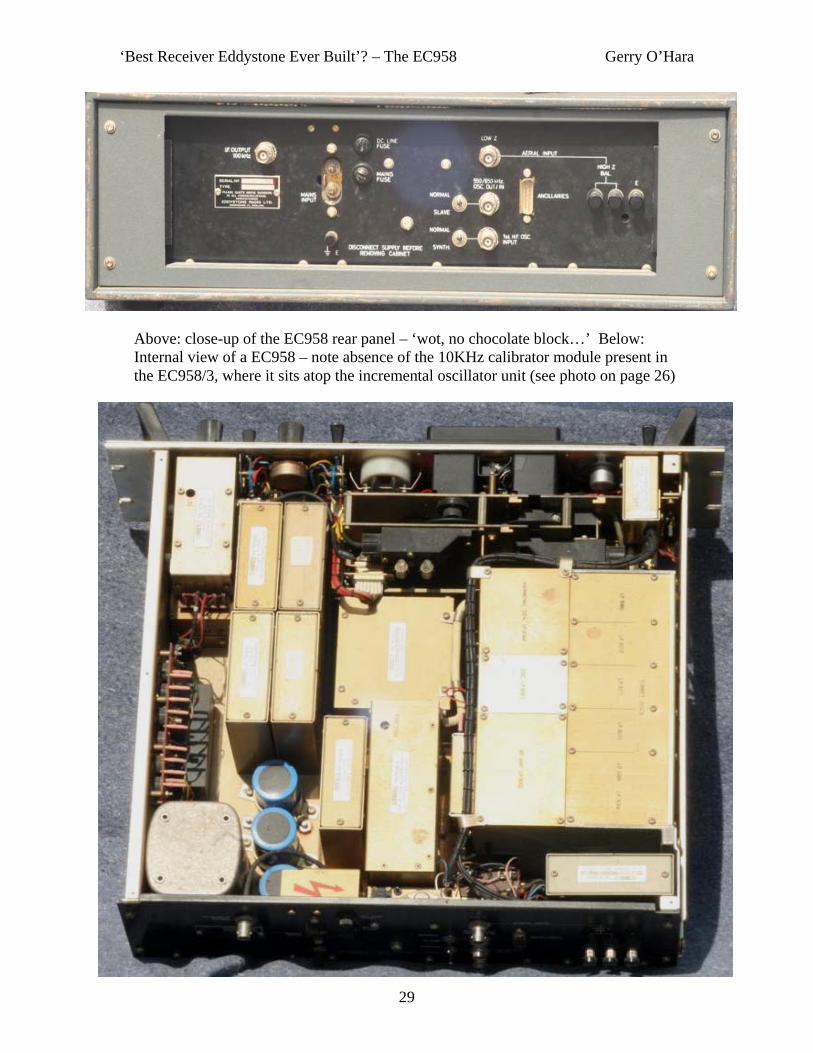
Above: close-up of the EC958 rear panel – ‘wot, no chocolate block…’ Below: Internal view of a EC958 – note absence of the 10KHz calibrator module present in the EC958/3, where it sits atop the incremental oscillator unit (see photo on page 26)

‘Best Receiver Eddystone Ever Built’? – The EC958 Gerry O’Hara
30
Above: close-up of the EC958 gain controls, Meter switch, Mode switch, Selectivity, BFO, and switch bank. Below: some more Wadley Loop ‘trannies’ mentioned in this article – clockwise from top left are the Yaesu FRG7, Standard C6500, Drake SSR-1 and Realistic DX-300

‘Best Receiver Eddystone Ever Built’? – The EC958 Gerry O’Hara
31
…and finally, an inside glance at one of the grand-daddies of Wadley Loop receivers, the RACAL RA117. Left: Under-chassis view of my RACAL RA117 (with screening covers removed) before I stripped it down for restoration (note - some bits are missing completely!). The main chassis is a single aluminium casting – the compartments are needed to keep spurious signals from the various LO’s and harmonic generator leaking through and interfering. Below left: identification of the various compartments. Below right: top view of my RA117 as received – a bit mucky innit?

Owner
Text Box
EC958/7E

Owner
Text Box
EC958/7E