
TS_100-1-1.pdf
161
Sanitary Waste & Vent TS 100‐1‐1 Friday 9:00am‐12:00pm Peter Kraut PE
Transcript of TS_100-1-1.pdf

Sanitary Waste & Vent
TS 100‐1‐1
Friday 9:00am‐12:00pm
Peter Kraut PE

Waste & VentWaste & Vent
Part 1Part 1October 28 2011October 28 2011 –– 9:009:00 –– 10:30 AM10:30 AMOctober 28, 2011 October 28, 2011 –– 9:00 9:00 –– 10:30 AM10:30 AM

Peter A Kraut P EPeter A Kraut P EPeter A. Kraut, P.E.Peter A. Kraut, P.E.
B.S. Architectural Engineering TechnologyB.S. Architectural Engineering TechnologyWentworth Institute of Technology, BostonWentworth Institute of Technology, Boston
Professional Engineer MechanicalProfessional Engineer MechanicalProfessional Engineer, MechanicalProfessional Engineer, MechanicalState of CaliforniaState of CaliforniaArizona, Connecticut, Hawaii, Indiana, Maryland, Arizona, Connecticut, Hawaii, Indiana, Maryland, Nevada, New Jersey, New York, North Carolina, Nevada, New Jersey, New York, North Carolina, Oregon, Pennsylvania, Texas, Virginia, Washington, Oregon, Pennsylvania, Texas, Virginia, Washington, WisconsinWisconsin
Over 15 years experience designing plumbing systemsOver 15 years experience designing plumbing systemsSouth Coast Engineering Group, Inc., South Coast Engineering Group, Inc., 20012001

IntroductionIntroductionIntroductionIntroduction
DefinitionsDefinitionsMaterialsMaterialsEngineeringEngineeringLayoutLayoutLayoutLayoutWasteWasteVentVent

IntroductionIntroductionIntroductionIntroduction
Uniform Plumbing Uniform Plumbing CodeCodeInternationalInternationalInternational International Plumbing CodePlumbing CodeNational StandardNational StandardNational Standard National Standard Plumbing CodePlumbing Code
State Plumbing State Plumbing CodesCodes

Drawings can be Drawings can be confusing…confusing…

DefinitionsDefinitions

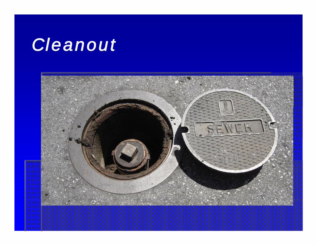
CleanoutCleanoutCleanoutCleanout
CleanoutCleanoutWall cleanoutWall cleanoutFloor CleanoutFloor CleanoutCleanout to gradeCleanout to grade
CleanoutCleanoutCleanoutCleanout
CleanoutCleanoutCleanoutCleanout
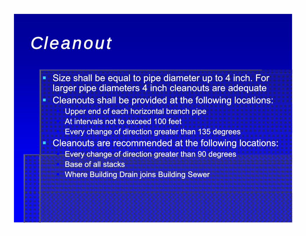
Size shall be equal to pipe diameter up to 4 inch. For Size shall be equal to pipe diameter up to 4 inch. For larger pipe diameters 4 inch cleanouts are adequatelarger pipe diameters 4 inch cleanouts are adequateCleanouts shall be provided at the following locations:Cleanouts shall be provided at the following locations:Cleanouts shall be provided at the following locations:Cleanouts shall be provided at the following locations:
Upper end of each horizontal branch pipeUpper end of each horizontal branch pipeAt intervals not to exceed 100 feetAt intervals not to exceed 100 feetEvery change of direction greater than 135 degreesEvery change of direction greater than 135 degreesEvery change of direction greater than 135 degreesEvery change of direction greater than 135 degrees
Cleanouts are recommended at the following locations:Cleanouts are recommended at the following locations:Every change of direction greater than 90 degreesEvery change of direction greater than 90 degreesB f ll t kB f ll t kBase of all stacksBase of all stacksWhere Building Drain joins Building SewerWhere Building Drain joins Building Sewer

CleanoutCleanoutCleanoutCleanout
Cleanouts are not required at the following Cleanouts are not required at the following locationslocations
Horizontal drain lines less than 5 feet except those Horizontal drain lines less than 5 feet except those serving sinks and urinalsserving sinks and urinalsHorizontal pipe installed on a slope of 72 degrees orHorizontal pipe installed on a slope of 72 degrees orHorizontal pipe installed on a slope of 72 degrees or Horizontal pipe installed on a slope of 72 degrees or less from the vertical angleless from the vertical angleAbove the first floor except the building drain and its Above the first floor except the building drain and its horizontal brancheshorizontal branchesWhere a two way building sewer cleanout can serve Where a two way building sewer cleanout can serve as the upper terminal cleanoutas the upper terminal cleanoutas the upper terminal cleanoutas the upper terminal cleanout

Fixture Unit (fu)Fixture Unit (fu)Fixture Unit (fu)Fixture Unit (fu)
A measure of the probable discharge into A measure of the probable discharge into the drainage system by various types of the drainage system by various types of plumbing fixtures.plumbing fixtures.Introduced in 1923 by Dr. Roy B. HunterIntroduced in 1923 by Dr. Roy B. Huntery yy y
TrapTrapTrapTrap
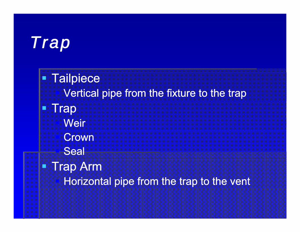
TailpieceTailpieceVertical pipe from the fixture to the trapVertical pipe from the fixture to the trap
TrapTrapWeirWeirCrownCrownSealSeal
Trap ArmTrap ArmHorizontal pipe from the trap to the ventHorizontal pipe from the trap to the vent

TrapTrapTrapTrap
a fitting or device that provides a liquid seal t t thto prevent the emission of sewer gas back through thegas back through the fixture

TrapTrapTrapTrap
Horizontal Distance of Trap Arms1
1 ¼” 2’-6”1 ½” 3’-6”2” 5’-0”3” 6’-0” 2
4” and larger 10’ 0”4 and larger 10 -01 ¼” per foot slope2 includes closet flange to vent
TrapTrapTrapTrap
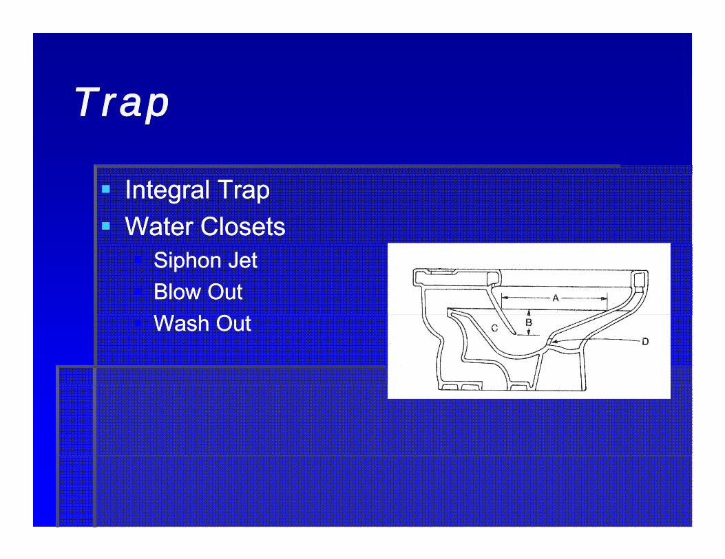
Integral TrapIntegral TrapWater ClosetsWater Closets
Siphon JetSiphon JetBlow OutBlow Out
OOWash OutWash Out

TrapTrapTrapTrap
Traps are subject to Traps are subject to positive and negative positive and negative pressurespressuresDeeper traps Deeper traps withstand greaterwithstand greaterwithstand greater withstand greater pressurespressuresProper trap armProper trap armProper trap arm Proper trap arm lengths prevent self lengths prevent self siphoningsiphoningsiphoningsiphoning

StackStackStackStack
StackStackVertical (waste) pipeVertical (waste) pipe( ) p p( ) p p
Vent StackVent StackVertical vent pipeVertical vent pipeVertical vent pipeVertical vent pipe
Stack VentStack VentVent off the top of the waste stackVent off the top of the waste stackVent off the top of the waste stackVent off the top of the waste stack

VentVentVentVent
Individual VentIndividual VentBranch VentBranch Vent
HorizontalHorizontalOne or more fixturesOne or more fixtures
Common VentCommon VentMore than oneMore than one
VentVentVentVent
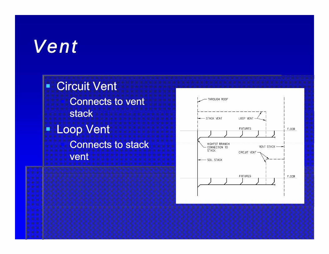
Circuit VentCircuit VentConnects to vent Connects to vent t kt kstackstack
Loop VentLoop VentConnects to stackConnects to stackConnects to stack Connects to stack ventvent

VentVentVentVent
Island VentIsland Vent

VentVentVentVent
Relief VentRelief Vent

Coordination is keyCoordination is keyCoordination is keyCoordination is key

VentVentVentVent
Wet VentWet Vent
WasteWasteWasteWaste
Building SewerBuilding SewerBuilding DrainBuilding DrainggBranchBranch

WasteWasteWasteWaste
Branch of the Building Drain
2 feet
Exterior Wall
Building DrainBuildingBuilding
Sewer
aBuilding Cleanout

MaterialsMaterials

PipePipePipePipe
Hubless CastHubless Cast--Iron Iron ––ASTM A 74; CISPI ASTM A 74; CISPI 301301301301

PipePipePipePipe

PipePipePipePipe
Copper (Type K,L, or Copper (Type K,L, or DWV) DWV) –– ASTM B 75; ASTM B 75; ASTM B 88ASTM B 88ASTM B 88ASTM B 88
PipePipePipePipe
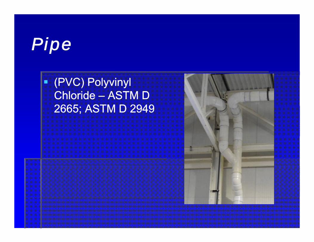
(PVC) Polyvinyl (PVC) Polyvinyl Chloride Chloride –– ASTM D ASTM D 2665 ASTM D 29492665 ASTM D 29492665; ASTM D 29492665; ASTM D 2949
PipePipePipePipe
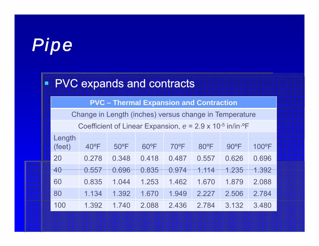
PVC expands and contractsPVC expands and contractsPVC – Thermal Expansion and Contraction
Change in Length (inches) versus change in TemperatureCoefficient of Linear Expansion, e = 2.9 x 10⁻⁵ in/in·ºF
LengthLength (feet) 40ºF 50ºF 60ºF 70ºF 80ºF 90ºF 100ºF20 0.278 0.348 0.418 0.487 0.557 0.626 0.69640 0 557 0 696 0 835 0 974 1 114 1 235 1 39240 0.557 0.696 0.835 0.974 1.114 1.235 1.39260 0.835 1.044 1.253 1.462 1.670 1.879 2.08880 1.134 1.392 1.670 1.949 2.227 2.506 2.784100 1.392 1.740 2.088 2.436 2.784 3.132 3.480

PipePipePipePipe
(ABS) Acrylonitrile (ABS) Acrylonitrile Butadiene Styrene Butadiene Styrene ––ASTM D 2661ASTM D 2661ASTM D 2661ASTM D 2661

PipePipePipePipe
ABS expands and contracts even more…ABS expands and contracts even more…ABS – Thermal Expansion and Contraction
Change in Length (inches) versus change in TemperatureCoefficient of Linear Expansion, e = 5.5 x 10⁻⁵ in/in·ºF
LengthLength (feet) 40ºF 50ºF 60ºF 70ºF 80ºF 90ºF 100ºF20 0.536 0.670 0.804 0.938 1.072 1.206 1.34040 1 070 1 340 1 610 1 880 2 050 2 420 2 69040 1.070 1.340 1.610 1.880 2.050 2.420 2.69060 1.609 2.010 2.410 2.820 3.220 3.620 4.02080 2.143 `2.680 3.220 3.760 4.290 4.830 5.360100 2.680 3.350 4.020 4.700 5.360 6.030 6.700

PipePipePipePipe
Allow for expansion Allow for expansion with bends, offsets, with bends, offsets,
i l di l dexpansion loops and expansion loops and expansion fittings expansion fittings where necessarywhere necessarywhere necessarywhere necessaryDo not strap pipe Do not strap pipe tight to structuraltight to structuraltight to structural tight to structural membersmembers

PipePipePipePipe
It is often less expensive to install all 2” It is often less expensive to install all 2” pipe in commercial projects than to carry, pipe in commercial projects than to carry, install and make transitions to 1½” and install and make transitions to 1½” and 1¼” fittings1¼” fittings
Not true in residential projectsNot true in residential projects2 ½” and 5” cast iron pipe are not2 ½” and 5” cast iron pipe are not2 ½ and 5 cast iron pipe are not 2 ½ and 5 cast iron pipe are not commercially available in most locationscommercially available in most locations

FittingsFittingsFittingsFittings
Quarter BendQuarter Bend Eight BendEight Bend
Sixteenth BendSixteenth Bend Long SweepLong SweepSixteenth BendSixteenth Bend Long SweepLong Sweep

FittingsFittingsFittingsFittings
Bends are named for the number of fittings to Bends are named for the number of fittings to make a full circle. Divide into 360 to get the make a full circle. Divide into 360 to get the
l E ll E langle. Examples:angle. Examples:quarter bend = 360/4 = 90 degreesquarter bend = 360/4 = 90 degreesSixth bend = 360/6 = 60 degressSixth bend = 360/6 = 60 degressSixth bend = 360/6 = 60 degressSixth bend = 360/6 = 60 degress
Use 45 degree and 90 degree bends when Use 45 degree and 90 degree bends when laying out waste and vent systemslaying out waste and vent systemslaying out waste and vent systemslaying out waste and vent systemsPerpendicular lines are easier to lay out and Perpendicular lines are easier to lay out and follow lines of structurefollow lines of structurefollow lines of structurefollow lines of structure

FittingsFittingsFittingsFittings
Combination Wye Combination Wye Double CombinationDouble Combinationand Eight Bendand Eight Bend
Sanitary TeeSanitary Tee Double Quarter BendDouble Quarter BendDouble Quarter BendDouble Quarter Bend
FittingsFittingsFittingsFittings
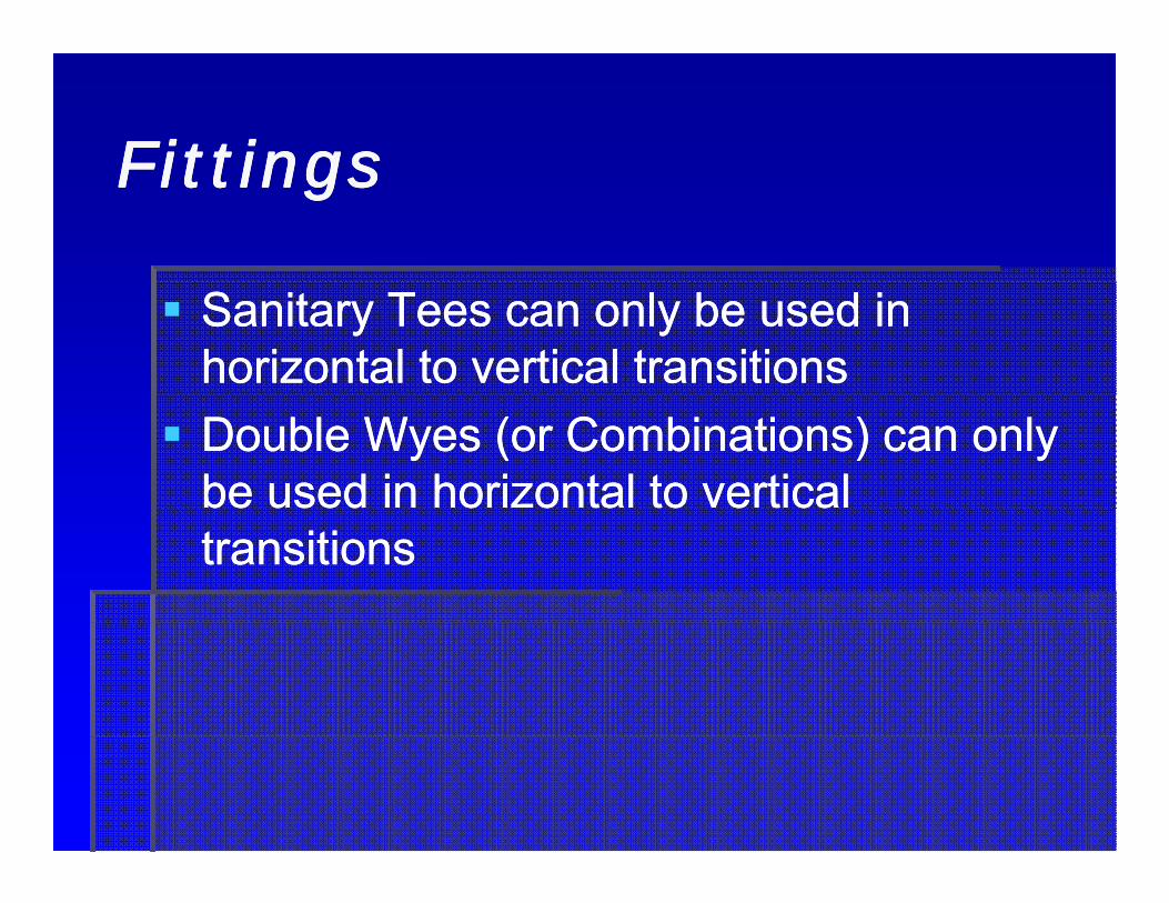
Sanitary Tees can only be used in Sanitary Tees can only be used in horizontal to vertical transitionshorizontal to vertical transitionsDouble Wyes (or Combinations) can only Double Wyes (or Combinations) can only be used in horizontal to vertical be used in horizontal to vertical transitionstransitions
EngineeringEngineering

DrainageDrainageDrainageDrainage
Gravity accelerates Gravity accelerates all mass 32 ft/secall mass 32 ft/sec22
DOWNDOWNDOWNDOWN

Slope is a dangerous thingSlope is a dangerous thingSlope is a dangerous thingSlope is a dangerous thing

DrainageDrainageDrainageDrainage
Assumes parallel flow Assumes parallel flow and atmospheric and atmospheric pressurepressurepressurepressureWaste pipe is sized to Waste pipe is sized to flow half fullflow half fullAir circulates in the Air circulates in the upper halfupper halfVelocity should beVelocity should beVelocity should be Velocity should be maintained at a maintained at a minimum of 2 feet per minimum of 2 feet per secondsecond

DrainageDrainageDrainageDrainage
The flow of sewage in an open channel is governed by The flow of sewage in an open channel is governed by the Manning formula:the Manning formula:
1 491 49V = V = 1.491.49 RRhh2/32/3 SS1/21/2
Where:Where: nnV = velocity in feet per secondV = velocity in feet per secondn = roughness coefficient of the pipen = roughness coefficient of the pipeRR = hydraulic radius in feet= hydraulic radius in feetRRhh = hydraulic radius in feet= hydraulic radius in feetS = slope in feet/footS = slope in feet/foot

DrainageDrainageDrainageDrainage
Values of S and S1/2
Slope(inches per foot)
S(feet per foot) S1/2
1/8 0.0104 0.1021/4 0.0208 0.1441/2 0.0416 0.2041/2 0.0416 0.204

DrainageDrainageDrainageDrainage
The hydraulic radius, RThe hydraulic radius, Rhh is equal to the cross sectional is equal to the cross sectional area of flow divided by the wetted perimeter.area of flow divided by the wetted perimeter.With partially filled pipes it can be difficult to calculateWith partially filled pipes it can be difficult to calculateWith partially filled pipes, it can be difficult to calculateWith partially filled pipes, it can be difficult to calculateWhen half full, it is equal to D/4When half full, it is equal to D/4When full, it is also equal to D/4When full, it is also equal to D/4When full, it is also equal to D/4When full, it is also equal to D/4

DrainageDrainageDrainageDrainageValues of Rh, Rh
2/3 and A for Half-full FlowPi Si R D/4 R 2/3 APipe Size(inches)
Rh = D/4(feet)
Rh2/3 A
(square feet)1 ½” 0.0335 0.1040 0.007062” 0 0417 0 1200 0 010902” 0.0417 0.1200 0.010902 ½” 0.0521 0.1396 0.017043” 0.0625 0.1570 0.024554” 0.0833 0.1910 0.043655” 0.1040 0.2210 0.068206” 0 1250 0 2500 0 098206 0.1250 0.2500 0.098208” 0.1670 0.3030 0.1746010” 0.2080 0.3510 0.2727012” 0.2500 0.3970 0.3927015” 0.3125 0.4610 0.61350

DrainageDrainageDrainageDrainage
For a 6” cast iron pipe flowing half full at For a 6” cast iron pipe flowing half full at 1% slope the velocity is:1% slope the velocity is:
V =V =1.491.49
0.123750.123752/32/3 0.010.011/21/2 = 2.6= 2.60 01450 0145
For a 6” cast iron pipe flowing For a 6” cast iron pipe flowing full full at 1% at 1% slope the velocityslope the velocity is the sameis the same
0.01450.0145
slope the velocity slope the velocity is the same …is the same …V =V =
1.491.490.123750.123752/32/3 0.010.011/21/2 = 2.6= 2.6
0 01450 01450.01450.0145

DrainageDrainageDrainageDrainage
To calculate flow rate from velocity:To calculate flow rate from velocity:
qq = 7.481 · 60 · V A= 7.481 · 60 · V Aqqqq ≈ 449 · ≈ 449 · V AV A
Where:Where:Where:Where:q = flow rate in gallons per minuteq = flow rate in gallons per minuteV = velocity in feet per secondV = velocity in feet per secondy py pA = area of the A = area of the flowflow in square feetin square feet

DrainageDrainageDrainageDrainage
A 6” cast iron pipe flowing A 6” cast iron pipe flowing half full at 2.6 half full at 2.6 feet per second will feet per second will convey:convey:
q = 449 · 2.6 · (0.09820 / 2) = 57.32q = 449 · 2.6 · (0.09820 / 2) = 57.32
A 6” cast iron pipe flowing half full at 2.6 A 6” cast iron pipe flowing half full at 2.6 feet per second will convey twice asfeet per second will convey twice asfeet per second will convey twice as feet per second will convey twice as muchmuch

DrainageDrainageDrainageDrainageUniform Flow Velocity and Flow Rate of Drains at ¼” per foot Slope
Pi Si F ll H lf F ll V H lf F ll F llPipe Size(inches)
Full or Half Full, V(feet per second)
Half Full, q(gallons per min.)
Full, q(gallons per min.)
1 ½” 1.85 5.85 11.72” 1 98 9 70 19 42” 1.98 9.70 19.42 ½” 2.30 17.60 35.23” 2.59 28.60 57.24” 2.91 57.00 114.05” 3.15 96.50 193.06” 3 58 157 50 315 06 3.58 157.50 315.08” 4.07 318.50 637.010” 4.69 574.00 1148.012” 5.31 936.00 1872.015” 6.15 1690.00 3380.0

DrainageDrainageDrainageDrainage
The flow of sewage in a The flow of sewage in a vertical pipe is governed by vertical pipe is governed by the stack formula:the stack formula:
Q = 27.8 rQ = 27.8 r5/35/3 d d 8/38/3
Where:Where:Q fl t i llQ fl t i llQ = flow rate in gallons Q = flow rate in gallons per minuteper minuter = area ratio of water to r = area ratio of water to t kt kstackstack
d = diameter in inchesd = diameter in inches77//2424
thsths fullfull2424

EngineeringEngineeringEngineeringEngineering
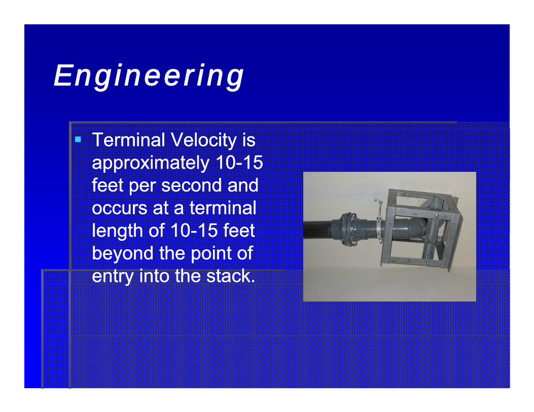
Terminal Velocity is Terminal Velocity is approximately 10approximately 10--15 15 f t d df t d dfeet per second and feet per second and occurs at a terminal occurs at a terminal length of 10length of 10--15 feet15 feetlength of 10length of 10--15 feet 15 feet beyond the point of beyond the point of entry into the stack.entry into the stack.yy

EngineeringEngineeringEngineeringEngineering

EngineeringEngineeringEngineeringEngineering
Hydraulic Jump Suds Pressure Zones
EngineeringEngineeringEngineeringEngineering
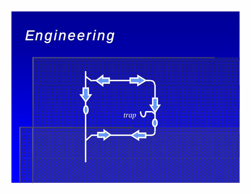
trap

LayoutLayout
LayoutLayoutLayoutLayout
ConsiderationsConsiderationsInstallation CostInstallation CostMaintenanceMaintenanceFinished AppearanceFinished Appearancepppp

Installation CostInstallation CostInstallation CostInstallation Cost
Layout at 90 degrees to structure for easy field Layout at 90 degrees to structure for easy field reference and even hanger spacingreference and even hanger spacingWhen turning odd angles roll in from the top atWhen turning odd angles roll in from the top atWhen turning odd angles, roll in from the top at When turning odd angles, roll in from the top at 45 degrees45 degrees
Elevation lossElevation lossSwing joints (2 elbows) require a cleanoutSwing joints (2 elbows) require a cleanout
Piping from smaller loads towards larger loads Piping from smaller loads towards larger loads ill k i i i iill k i i i iwill keep pipe sizes to a minimumwill keep pipe sizes to a minimum
Minimize pipe slopeMinimize pipe slope

MaintenanceMaintenance
Maximize pipe slopeMaximize pipe slopeFaster velocitiesFaster velocities
Do NOT oversize pipeDo NOT oversize pipeSlower velocitiesSlower velocitiesSlower velocitiesSlower velocities
Provide cleanouts everywhereProvide cleanouts everywhereIn backIn back ofof house areashouse areasIn backIn back--ofof--house areashouse areasLocate cleanouts above urinalsLocate cleanouts above urinals

Finished AppearanceFinished AppearanceFinished AppearanceFinished Appearance
Locate cleanouts below urinalsLocate cleanouts below urinalsCareful with ADACareful with ADA
Indicate all necessary access panels, Indicate all necessary access panels, cleanouts, etc.cleanouts, etc.cleanouts, etc.cleanouts, etc.
Group trap primers with water hammer Group trap primers with water hammer arrestors and valvesarrestors and valves
Coordinate pipe chasesCoordinate pipe chases

LayoutLayoutLayoutLayout

LayoutLayoutLayoutLayout

LayoutLayoutLayoutLayout
LayoutLayoutLayoutLayout
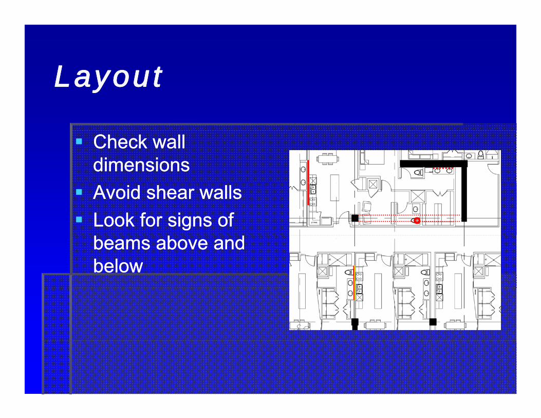
Check wall Check wall dimensionsdimensionsAvoid shear wallsAvoid shear wallsLook for signs of Look for signs of beams above and beams above and belowbelow

LayoutLayoutLayoutLayout
Avoid venting across Avoid venting across beamsbeams24” max tailpiece24” max tailpieceBeam penetrations Beam penetrations may be allowed in may be allowed in the middle 1/3 of the the middle 1/3 of the structural memberstructural memberstructural memberstructural member
Check with Structural Check with Structural EngineerEngineergg

LayoutLayoutLayoutLayout
Avoid Wall and Avoid Wall and Column FootingsColumn FootingsFollow CodesFollow CodesCheck with structural Check with structural engineerengineerSleeve Footings Sleeve Footings
hhwhere necessarywhere necessary

LayoutLayoutLayoutLayout

Check what’s belowCheck what’s belowCheck what s belowCheck what s below

LayoutLayoutLayoutLayout
Grease wasteGrease waste¼” per foot slope¼” per foot slopep pp pGrease producing fixtures onlyGrease producing fixtures onlyHeat trace if necessaryHeat trace if necessaryyyProvide additional cleanoutsProvide additional cleanouts
LayoutLayoutLayoutLayout
National Electric CodeNational Electric Code
Stay out of the electric room !Stay out of the electric room !Stay out of the electric room !Stay out of the electric room !Avoid passing over any equipment where Avoid passing over any equipment where l k dl k dleakage may cause damageleakage may cause damage

National Electric CodeNational Electric CodeNational Electric CodeNational Electric Code
Depth of Working Space. Depth of Working Space. The depth of the working The depth of the working space in the direction of space in the direction of access to live parts shall access to live parts shall not be less than not be less than indicated. Distances indicated. Distances shall be measured from shall be measured from the live parts if such are the live parts if such are exposed or from the exposed or from the ppenclosure front or enclosure front or opening if such are opening if such are enclosed.enclosed.

National Electric CodeNational Electric CodeNational Electric CodeNational Electric Code
Width of Working Space. Width of Working Space. The width of the working The width of the working space in front of thespace in front of thespace in front of the space in front of the electric equipment shall electric equipment shall be the width of the be the width of the eq ipment or 30 in (762eq ipment or 30 in (762equipment or 30 in. (762 equipment or 30 in. (762 mm), whichever is mm), whichever is greater. In all cases, the greater. In all cases, the work space shall permit work space shall permit at least a 90 degree at least a 90 degree opening of equipmentopening of equipmentopening of equipment opening of equipment doors or hinged panels.doors or hinged panels.

National Electric CodeNational Electric CodeNational Electric CodeNational Electric Code
Height of Working Space. The minimum Height of Working Space. The minimum headroom of working spaces about headroom of working spaces about
i i t it hb di i t it hb dservice equipment, switchboards, service equipment, switchboards, panelboards, or motor control centers panelboards, or motor control centers shall be 6 ½ ft (1 98 m) Where theshall be 6 ½ ft (1 98 m) Where theshall be 6 ½ ft (1.98 m). Where the shall be 6 ½ ft (1.98 m). Where the electrical equipment exceeds 6½ ft (1 .98 electrical equipment exceeds 6½ ft (1 .98 m) in height, the minimum headroomm) in height, the minimum headroomm) in height, the minimum headroom m) in height, the minimum headroom shall not be less than the height of the shall not be less than the height of the equipment.equipment.q pq p

National Electric CodeNational Electric CodeNational Electric CodeNational Electric Code
The space equal to the width and depth The space equal to the width and depth of the equipment and extending from the of the equipment and extending from the fl t h i ht f 6 ft (1 83 ) b thfl t h i ht f 6 ft (1 83 ) b thfloor to a height of 6 ft (1.83 m) above the floor to a height of 6 ft (1.83 m) above the equipment or to the structural ceiling, equipment or to the structural ceiling, whichever is lower shall be dedicated towhichever is lower shall be dedicated towhichever is lower, shall be dedicated to whichever is lower, shall be dedicated to the electrical installation. No piping, the electrical installation. No piping, ducts, or equipment foreign to theducts, or equipment foreign to theducts, or equipment foreign to the ducts, or equipment foreign to the electrical installation shall be located in electrical installation shall be located in this zone.this zone.

National Electric CodeNational Electric CodeNational Electric CodeNational Electric Code

Damn electrical Damn electrical engineers!engineers!

WasteWasteWasteWaste
Drainage Fixture Unit ValuesFixture Min. Branch Private Public AssemblyBathtub 1 ½” 2.0 2.0ClothesWasher 3.0 3.0 3.0Dishwasher 1 ½” 2.0 2.0 2.0DrinkingFountain 1 ¼” 0 5 0 5 1 0Drinking Fountain 1 ¼ 0.5 0.5 1.0Floor Drain 2” 2.0 2.0 2.0Shower 2” 2.0 2.0 2.0Kitchen Sink 1 ½” 2.0 2.0Mop Sink 2” 3.0 3.0Urinal 2” 2.0 2.0 5.0Urinal 2 2.0 2.0 5.0Water Closet 3” 3.0 4.0 6.0

WasteWasteWasteWasteMaximum Loading and Length of Waste Piping
Pipe Size (inches) 1 ¼ 1 ½ 2 2 ½ 3 4 5 6 8Fixture Units- ¼” per foot slope 1 1 1 8 2 14 2 35 3 216 428 720 2640
- 1/8” per foot slope n/a n/a n/a n/a n/a 172 342 576 2112
- vertical 1 2 16 32 48 4 256 600 1380 3600
Length (feet)Length (feet)- horizontal unlimited- vertical 45 65 85 148 212 300 390 510 750
1 except sinks, urinals, dishwashers
2 except water closets
3 maximum 3 water closets
4 maximum 4 water closets

WasteWasteWasteWaste
Discharge Capacity(for intermittent flow)
Flow Rate( ll i )
Load(fi t it )(gallons per min) (fixture units)
Up to 7 ½ 18 – 15 2 Maximum Trap Loading
16 – 30 431 - 50 6For continuous flow allow 2 fixture
Pipe Size(inches)
Loading(fixture units)
1 ¼” 1For continuous flow, allow 2 fixture units for each gallon per minute 1 ½” 3
2” 43” 63 64” 8


VentVent
VentVentVentVent
Sized based on load in fixture unitsSized based on load in fixture units… and total developed length… and total developed lengthp gp g
Distance from the vent connection at the Distance from the vent connection at the waste system to the open airwaste system to the open airy py p

VentVentVentVentMaximum Loading and Length of Vent Piping
Pipe Size (inches) 1 ¼ 1 ½ 2 2 ½ 3 4 5 6 8Fixture Units 1 8 24 48 84 256 600 1380 3600
Length (feet) 45 60 120 180 212 300 390 510 750g ( )- total 45 60 120 180 212 300 390 510 750- horizontal 15 20 40 60 70 100 130 170 250Fixture UnitsFixture Units(unlimited length) n/a 1 8 24 48 84 256 600 1380

VentVentVentVent
Vents must rise vertically a minimum of 6 Vents must rise vertically a minimum of 6 inches above flood level rim of fixture inches above flood level rim of fixture before they turn horizontalbefore they turn horizontal
Flat ventFlat ventVent pipes slope back to fixturesVent pipes slope back to fixturesTerminate through roof 10 feet minimumTerminate through roof 10 feet minimumTerminate through roof 10 feet minimum Terminate through roof 10 feet minimum from air intakesfrom air intakes

VentVentVentVent
Vents shall be at least oneVents shall be at least one--half the diameter of half the diameter of the drain servedthe drain servedVent shall not be less than 1¼ inches inVent shall not be less than 1¼ inches inVent shall not be less than 1¼ inches in Vent shall not be less than 1¼ inches in diameterdiameter(IPC) Every Building shall have a main vent(IPC) Every Building shall have a main vent(IPC) Every Building shall have a main vent (IPC) Every Building shall have a main vent sized not less than half the building drain and sized not less than half the building drain and not less than 2 inchesnot less than 2 inches(UPC) The total cross sectional area of all (UPC) The total cross sectional area of all vents shall be equal to or greater than the total vents shall be equal to or greater than the total cross sectional area of the building sewercross sectional area of the building sewercross sectional area of the building sewercross sectional area of the building sewer

VentVentVentVent
Assuming 200 fixture units, the building Assuming 200 fixture units, the building sewer is 6”Ø ≈ 28.26 sq.in.sewer is 6”Ø ≈ 28.26 sq.in.(3) 3” Ø vents might work for fixture units, (3) 3” Ø vents might work for fixture units, but (3) 3”Ø ≈ 21.20 sq.in.but (3) 3”Ø ≈ 21.20 sq.in.( ) Ø q( ) Ø q
Separate some fixtures to a fourth 3”Ø ventSeparate some fixtures to a fourth 3”Ø ventor Increase two vents to 4”or Increase two vents to 4”or Increase two vents to 4 or Increase two vents to 4


Waste & Vent Part 1Waste & Vent Part 1Waste & Vent, Part 1Waste & Vent, Part 1

BibliographyBibliographyBibliographyBibliography
Alf d S l P EAlf d S l P E Ad d Pl bi T h lAd d Pl bi T h l C iC iAlfred Steele, P.E., Alfred Steele, P.E., Advanced Plumbing TechnologyAdvanced Plumbing Technology, Construction , Construction Industry Press, Elmhurst, IL 1984Industry Press, Elmhurst, IL 1984Alfred Steele, P.E., Alfred Steele, P.E., Engineered Plumbing DesignEngineered Plumbing Design, Second edition, , Second edition, Construction Industry Press, Elmhurst, IL, 1982Construction Industry Press, Elmhurst, IL, 1982American Society of Plumbing Engineers, American Society of Plumbing Engineers, Sanitary Drainage And Vent Sanitary Drainage And Vent Piping SystemsPiping Systems, Chicago, IL, 2006, Chicago, IL, 2006Cast Iron Soil Pipe Institute, Cast Iron Soil Pipe Institute, Cast Iron Soil Pipe & Fittings Specifier’s Cast Iron Soil Pipe & Fittings Specifier’s GuideGuide, Chattanooga, TN, Chattanooga, TNInternational Association of Plumbing and Mechanical Officials, International Association of Plumbing and Mechanical Officials, Uniform Uniform Plumbing Code Illustrated Training ManualPlumbing Code Illustrated Training Manual, Walnut, CA, 1997, Walnut, CA, 1997International Association of Plumbing and Mechanical Officials, International Association of Plumbing and Mechanical Officials, 2006 2006 Uniform Plumbing Code, Uniform Plumbing Code, Ontario, CA 2006Ontario, CA 2006International Code Council Inc., International Code Council Inc., 2006 International Plumbing Code2006 International Plumbing Code, , Country Club Hills, IL, 2006Country Club Hills, IL, 2006National Fire Protection Association, National Fire Protection Association, National Electrical CodeNational Electrical Code, Quincy, , Quincy, MA, 2001MA, 2001

QuestionsQuestionsQuestionsQuestions

Waste & VentWaste & Vent
Part 2Part 2October 28 2011 10:45October 28 2011 10:45––12:15 AM12:15 AMOctober 28, 2011 10:45October 28, 2011 10:45––12:15 AM12:15 AM

IntroductionIntroductionIntroductionIntroduction
Indirect WasteIndirect WasteCombination Waste and VentCombination Waste and VentWet VentingWet VentingAlternative VentingAlternative VentingBackwater ValvesBackwater ValvesInterceptorsInterceptorsppSeptic SystemsSeptic SystemsSewage EjectorsSewage EjectorsSewage EjectorsSewage Ejectors

Indirect WasteIndirect Waste

Indirect WasteIndirect WasteIndirect WasteIndirect Waste
A waste pipe that A waste pipe that does not connect does not connect directly with thedirectly with thedirectly with the directly with the drainage system, but drainage system, but that discharges into that discharges into the drainage system the drainage system through an air break through an air break or air gap into a trapor air gap into a trapor air gap into a trap, or air gap into a trap, fixture, receptor or fixture, receptor or interceptorinterceptor
Indirect WasteIndirect WasteIndirect WasteIndirect Waste
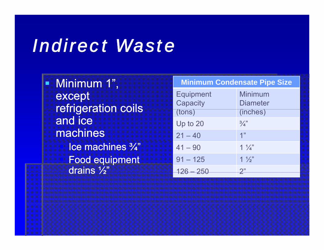
Minimum 1”, Minimum 1”, except except refrigeration coilsrefrigeration coils
Minimum Condensate Pipe SizeEquipment Capacity(t )
MinimumDiameter(i h )refrigeration coils refrigeration coils
and ice and ice machinesmachines
(tons) (inches)Up to 20 ¾”21 – 40 1”
Ice machines ¾”Ice machines ¾”Food equipment Food equipment drains ½”drains ½”
41 – 90 1 ¼”91 – 125 1 ½”126 – 250 2”drains ½drains ½ 126 250 2

Indirect WasteIndirect WasteIndirect WasteIndirect Waste
Maximum length 15’Maximum length 15’Or, trapped but not necessarily ventedOr, trapped but not necessarily ventedBar sinks 5’Bar sinks 5’
Food handling fixtures may not be Food handling fixtures may not be combinedcombinedCleanoutsCleanouts

Air BreakAir BreakAir BreakAir Break
A physical separation A physical separation which may be a low which may be a low i l t i t th i di ti l t i t th i di tinlet into the indirect inlet into the indirect waste receptor from waste receptor from the fixture appliancethe fixture appliancethe fixture, appliance, the fixture, appliance, or device indirectly or device indirectly connectedconnected
Air GapAir GapAir GapAir Gap
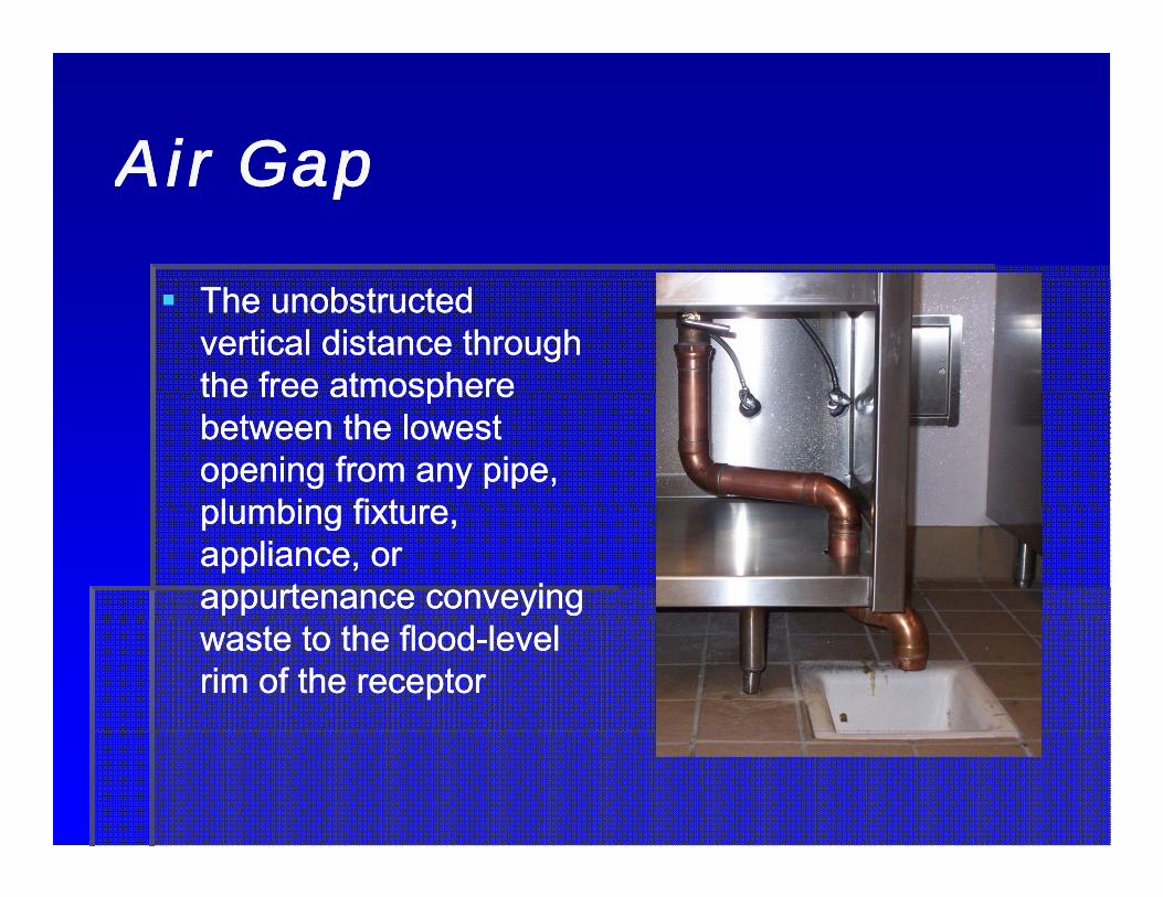
The unobstructed The unobstructed vertical distance through vertical distance through the free atmospherethe free atmospherethe free atmosphere the free atmosphere between the lowest between the lowest opening from any pipe, opening from any pipe, pl mbing fi t repl mbing fi t replumbing fixture, plumbing fixture, appliance, or appliance, or appurtenance conveying appurtenance conveying waste to the floodwaste to the flood--level level rim of the receptorrim of the receptor

Indirect Waste ReceptorsIndirect Waste ReceptorsIndirect Waste ReceptorsIndirect Waste Receptors
Readily accessible (no access panel)Readily accessible (no access panel)No toilet room, closet, cupboard or No toilet room, closet, cupboard or , , p, , pstoreroomstoreroomCondensate to a sink or lavatory tailpieceCondensate to a sink or lavatory tailpieceCondensate to a sink or lavatory tailpiece Condensate to a sink or lavatory tailpiece must discharge in the area controlled by must discharge in the area controlled by the same person controlling the airthe same person controlling the airthe same person controlling the air the same person controlling the air conditioning unitconditioning unit

Access is importantAccess is importantAccess is importantAccess is important
Combination Waste and Combination Waste and VentVentVentVent

Comb Waste and VentComb Waste and VentComb Waste and VentComb Waste and Vent
Only where structural conditions prevent Only where structural conditions prevent conventional ventingconventional ventingMust be approved by AHJMust be approved by AHJNo water closets or urinalsNo water closets or urinalsNo water closets or urinalsNo water closets or urinalsAdditional vent required for branches Additional vent required for branches longer than 15’longer than 15’longer than 15longer than 15

Comb Waste and VentComb Waste and VentComb Waste and VentComb Waste and Vent
Waste pipes two (2) pipe sizes larger Waste pipes two (2) pipe sizes larger than codethan code
2 → 2 ½” → 32 → 2 ½” → 34” → 5” → 6”4” → 5” → 6”
No vertical pipe except tailpiecesNo vertical pipe except tailpieces24” maximum tailpieces24” maximum tailpieces45 degree vertical offsets allowed in 45 degree vertical offsets allowed in branch piping, onlybranch piping, only

Comb Waste and VentComb Waste and VentComb Waste and VentComb Waste and Vent

Wet VentingWet Venting

Wet VentingWet VentingWet VentingWet Venting
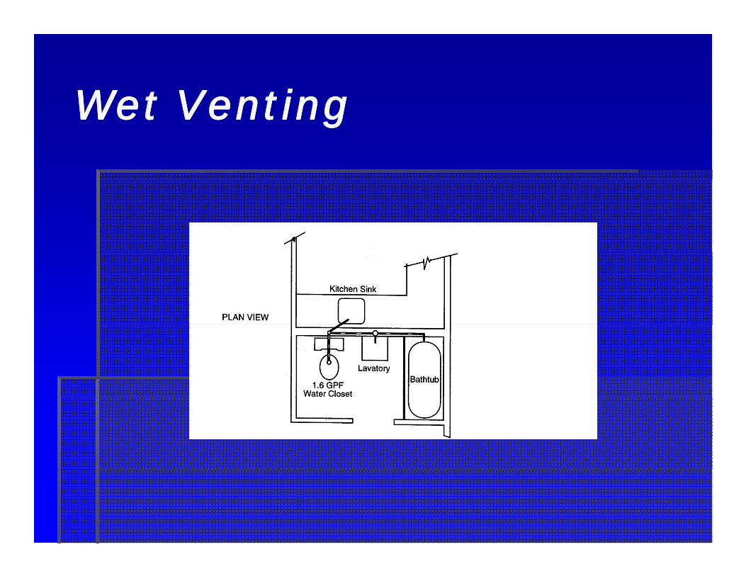
A vent that vents a particular fixture and A vent that vents a particular fixture and at the same time serves as a waste to at the same time serves as a waste to
i th di h f th fi ti th di h f th fi treceive the discharge from other fixturesreceive the discharge from other fixturesFixtures must be located on the same Fixtures must be located on the same flflfloorfloorExamples: high low drinking fountains, Examples: high low drinking fountains, b th l t t t l tb th l t t t l tbathroom groups, lavatory to water closetbathroom groups, lavatory to water closetCheck local codesCheck local codes
Wet VentingWet VentingWet VentingWet Venting

Wet VentingWet VentingWet VentingWet Venting

Alternative VentingAlternative Venting

Alternative VentingAlternative Venting
Air Admittance ValveAir Admittance ValvePrevents selfPrevents self--siphoningsiphoningIndividual fixturesIndividual fixturesAir flows in not outAir flows in not out

Alternative VentingAlternative VentingAlternative VentingAlternative Venting
AeratorAeratorDisrupts stack actionDisrupts stack action

Backwater ValvesBackwater Valves

Backwater ValvesBackwater ValvesBackwater ValvesBackwater Valves
A device or valve installed in the building drain or sewer pipe A device or valve installed in the building drain or sewer pipe where a sewer is subject to backflow, and which prevents where a sewer is subject to backflow, and which prevents drainage or waste from backing into a low level or fixtures and drainage or waste from backing into a low level or fixtures and g gg gcausing a flooding condition.causing a flooding condition.Required for fixtures below the next upstream manholeRequired for fixtures below the next upstream manholeNot allowed on fixtures Not allowed on fixtures aboveabove the next upstream manholethe next upstream manholepp

Backwater ValvesBackwater ValvesBackwater ValvesBackwater Valves

Backwater ValvesBackwater ValvesBackwater ValvesBackwater Valves

It looked good in plan It looked good in plan view …view …

InterceptorsInterceptors

InterceptorsInterceptorsInterceptorsInterceptors
A device designed and installed to separate and retain A device designed and installed to separate and retain for removal, by automatic or manual means, for removal, by automatic or manual means, deleterious, hazardous or undesirable matter from deleterious, hazardous or undesirable matter from normal wastes, while permitting normal sewage or normal wastes, while permitting normal sewage or wastes to discharge into the drainage system by wastes to discharge into the drainage system by gravity, but that discharges into the drainage system gravity, but that discharges into the drainage system g y g g yg y g g ythrough an air break or air gap into a trap, fixture, through an air break or air gap into a trap, fixture, receptor or interceptorreceptor or interceptor
GreaseGreaseOilOilSolidsSolidsLintLint

InterceptorsInterceptorsInterceptorsInterceptors

InterceptorsInterceptorsInterceptorsInterceptorsGrease Interceptor SizingGrease Interceptor Sizing
Drainage Fixture Units Interceptor Volume (gallons)8 50021 75021 75035 1,00090 1,250172 1,500216 2,000307 2 500307 2,500342 3,000428 4,000576 5,000720 7,500

InterceptorsInterceptorsInterceptorsInterceptorsHydromechanical Grease Interceptor (HGI) SizingHydromechanical Grease Interceptor (HGI) Sizing
Drainage Fixture Units Interceptor Volume (gallons)8 2010 2510 2513 3520 5035 75172 100216 150216 150342 200428 250576 350720 500

Septic SystemsSeptic Systems
Septic systemsSeptic systemsSeptic systemsSeptic systems
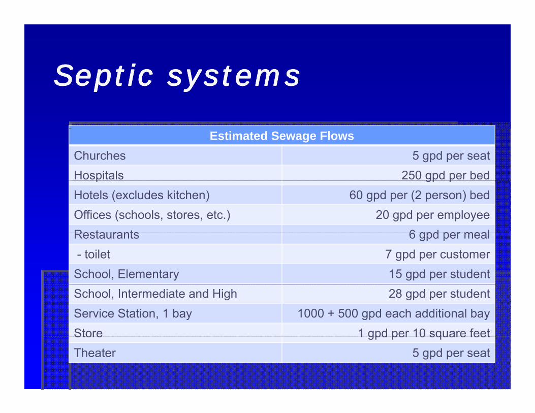
Estimated Sewage FlowsChurches 5 gpd per seatHospitals 250 gpd per bedp gp pHotels (excludes kitchen) 60 gpd per (2 person) bedOffices (schools, stores, etc.) 20 gpd per employeeRestaurants 6 gpd per mealRestaurants 6 gpd per meal- toilet 7 gpd per customerSchool, Elementary 15 gpd per studentSchool, Intermediate and High 28 gpd per studentService Station, 1 bay 1000 + 500 gpd each additional bayStore 1 gpd per 10 square feetStore 1 gpd per 10 square feetTheater 5 gpd per seat

Septic systemsSeptic systemsSeptic systemsSeptic systemsCapacity of Septic Tanksp y p
Single Family 1(bedrooms)
Multi-Family 2(1 bedroom units)
Other 3(fixture units)
1 – 2 15 7501 2 15 7503 20 1,0004 2 25 1,2005 6 3 33 1 5005 – 6 3 33 1,500
4 45 2,0005 55 2,2506 60 2,500
1 Each additional bedroom, add 150 gallons2 Each additional unit add 250 gallonsEach additional unit, add 250 gallons3 Each additional fixture unit, add 25 gallons

Septic systemsSeptic systemsSeptic systemsSeptic systems
Leach Field DimensionsMinimum Maximum
Leach 100 ft
Square Feet of Leaching Area / 100 gal Septic
Maximum Septic Tank
Size (gallons)20 25 7500Lines
Width 18 in 36 inSpacing 6 ft
20-25 750040 500090 3500Spacing 6 ft
Depth 12 inGrade Level 3 in /100 ftFill 12 i
120 3000
Filler Under
12 in
Filler Over 2 in

Septic systemsSeptic systemsSeptic systemsSeptic systems
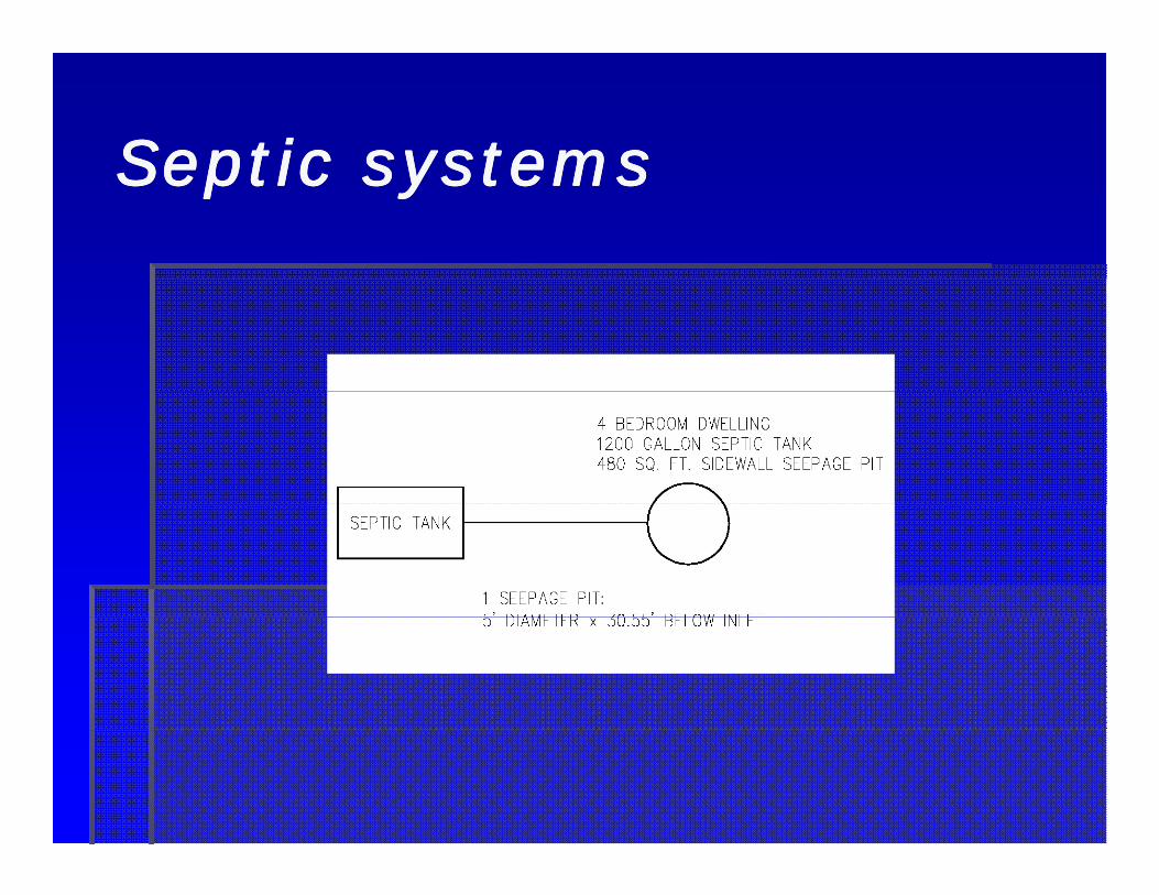
Septic systemsSeptic systemsSeptic systemsSeptic systems

Septic systemsSeptic systemsSeptic systemsSeptic systems
Design Criteria of Five Typical SoilsType of Soil Square Feet of
Leaching Area / 100 gal S ti
Maximum absorption (gal /sf /24 hr)
SepticCoarse Sand or Gravel 20 5.0Fine Sand 25 4.0Sandy Loam or SandyClay
40 2.5
Clay with Considerable 90 1.1Sand or GravelClay with Little Sand or Gravel
120 0.8
Septic systemsSeptic systemsSeptic systemsSeptic systems
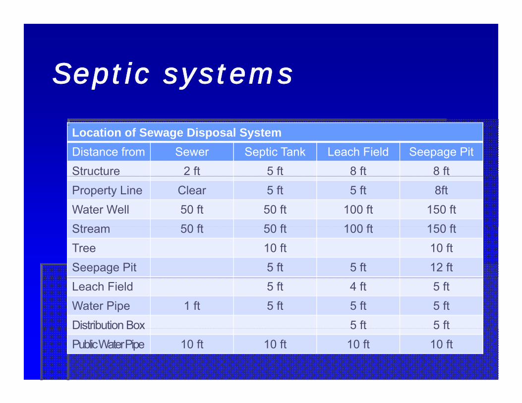
Location of Sewage Disposal SystemDistance from Sewer Septic Tank Leach Field Seepage PitStructure 2 ft 5 ft 8 ft 8 ftProperty Line Clear 5 ft 5 ft 8ftWater Well 50 ft 50 ft 100 ft 150 ftStream 50 ft 50 ft 100 ft 150 ftStream 50 ft 50 ft 100 ft 150 ftTree 10 ft 10 ftSeepage Pit 5 ft 5 ft 12 ftLeach Field 5 ft 4 ft 5 ftWater Pipe 1 ft 5 ft 5 ft 5 ftDistribution Box 5 ft 5 ftDistribution Box 5 ft 5 ftPublic Water Pipe 10 ft 10 ft 10 ft 10 ft

Sewage EjectorsSewage Ejectors

Sewage EjectorsSewage EjectorsSewage EjectorsSewage Ejectors
A device (pump) for lifting sewage A device (pump) for lifting sewage automatically up into the gravity drainage automatically up into the gravity drainage
ttsystemsystemSimplexSimplexDuplexDuplex
100% / 100%100% / 100%Required for commercial installationsRequired for commercial installationsRequired for commercial installationsRequired for commercial installations
50% / 50%50% / 50%Some protection during pump failureSome protection during pump failure

Sewage EjectorsSewage EjectorsSewage EjectorsSewage Ejectors
Fiberglass BasinsFiberglass BasinsAntiAnti--Floatation flange keeps basin from Floatation flange keeps basin from g pg p“floating” when the groundwater rises“floating” when the groundwater rises
Concrete PitsConcrete PitsReinforcement holds back weight of earth on Reinforcement holds back weight of earth on side wallsside walls

Sewage EjectorsSewage EjectorsSewage EjectorsSewage Ejectors
How many things How many things can go wrong with can go wrong with
i t ll ti ?i t ll ti ?one installation?one installation?

Sewage EjectorsSewage EjectorsSewage EjectorsSewage Ejectors
Trash cans are not Trash cans are not an approved materialan approved materialPits must be water Pits must be water proofproofEjector pits must be Ejector pits must be located away from located away from foundation loadsfoundation loadsfoundation loadsfoundation loads

Sewage EjectorsSewage EjectorsSewage EjectorsSewage Ejectors
Conduits must be sealedConduits must be sealedThe inlet must be higher The inlet must be higher than the working volumethan the working volumethan the working volumethan the working volumeThe pump stop must be The pump stop must be high enough to keep the high enough to keep the g g pg g ppump wetpump wetDischarge pipes require Discharge pipes require shut off valves andshut off valves andshut off valves and shut off valves and check valvescheck valves

Sewage EjectorsSewage EjectorsSewage EjectorsSewage Ejectors
Duplex pumps must Duplex pumps must share the same share the same
l f tl f tvolume of watervolume of waterPump basins should Pump basins should be sized for 3 minutebe sized for 3 minutebe sized for 3 minute be sized for 3 minute run timerun timeBasin must beBasin must beBasin must be Basin must be ventedvented

Sewage EjectorsSewage EjectorsSewage EjectorsSewage Ejectors
Flow rate of pump = peak flow rate of Flow rate of pump = peak flow rate of sewage coming insewage coming inMultiply fixture units by 0.5 to get gallons Multiply fixture units by 0.5 to get gallons per minuteper minutepp
ororConvert fixture units to gallons perConvert fixture units to gallons perConvert fixture units to gallons per Convert fixture units to gallons per minute using Hunter’s Curveminute using Hunter’s Curve

Sewage EjectorsSewage EjectorsSewage EjectorsSewage Ejectors
Head is a measure of resistanceHead is a measure of resistance1 psi = 2.31 feet of head1 psi = 2.31 feet of headpp
Pump head = suction head + friction Pump head = suction head + friction head + lifthead + lifthead lifthead lift
Suction head = 0 for submersible pumpsSuction head = 0 for submersible pumpsFriction head = resistance in pipe +Friction head = resistance in pipe +Friction head resistance in pipe + Friction head resistance in pipe + resistance in fittingresistance in fittingLift = elevation change from the bottom ofLift = elevation change from the bottom ofLift elevation change from the bottom of Lift elevation change from the bottom of the basin to the dischargethe basin to the discharge

Sewage EjectorsSewage EjectorsSewage EjectorsSewage Ejectors
Total Developed Length = Pipe length + Total Developed Length = Pipe length + Equivalent fitting length (depends on pipe Equivalent fitting length (depends on pipe
t i l)t i l)material)material)
Diameter of Diameter of fitting (in)fitting (in)
4545°° bend (ft)bend (ft) 9090°° bend (ft)bend (ft) Gate valve Gate valve (ft)(ft)
check valve check valve (ft)(ft)
22 4’4’ 7’7’ 1 3’1 3’ 11’11’22 4’4’ 7’7’ 1.3’1.3’ 11’11’33 6’6’ 10’10’ 2’2’ 16’16’44 8’8’ 14’14’ 2.7’2.7’ 22’22’66 12’12’ 20’20’ 4’4’ 31’31’

Sewage EjectorsSewage EjectorsSewage EjectorsSewage Ejectors
ExampleExample60’ of 3” straight pipe60’ of 3” straight pipeg p pg p p(3) 3” 45(3) 3” 45°° bendsbends(2) 3” 90(2) 3” 90°° bendsbends( )( )(1) 3” gate valve(1) 3” gate valve(1) 3” check valve(1) 3” check valve(1) 3 check valve(1) 3 check valve60 + 3x(6) + 2x(10) + 2 + 1660 + 3x(6) + 2x(10) + 2 + 16= 116 feet equivalent length= 116 feet equivalent length 116 feet, equivalent length 116 feet, equivalent length

Sewage EjectorsSewage EjectorsSewage EjectorsSewage Ejectors
ExampleExample250 GPM in a 3” pipe250 GPM in a 3” pipeFriction = 6.5 psi per Friction = 6.5 psi per 100 feet of pipe100 feet of pipe
6.5 x 116 / 1006.5 x 116 / 1006.5 x 116 / 1006.5 x 116 / 100= 7.54 psi= 7.54 psi
Convert psi to feetConvert psi to feet= 7.54 x 2.31 = 7.54 x 2.31 ftft/psi/psi= 17.4 feet= 17.4 feet
Note: 10Note: 10 ftft/sec/secNote: 10 Note: 10 ftft/sec/sec

Sewage EjectorsSewage EjectorsSewage EjectorsSewage Ejectors
Pump head = suction head + friction Pump head = suction head + friction head + lifthead + liftExampleExample
Elevation of discharge = 167’Elevation of discharge = 167’Elevation of discharge 167Elevation of discharge 167Elevation of sump cover = 148’Elevation of sump cover = 148’Depth of basin 8’ (assumed)Depth of basin 8’ (assumed)Depth of basin 8 (assumed)Depth of basin 8 (assumed)Lift = 167 Lift = 167 -- 148 + 8 = 27 feet148 + 8 = 27 feet

Sewage EjectorsSewage EjectorsSewage EjectorsSewage Ejectors
Pump Head =Pump Head =0’, suction head0’, suction head17.4’, friction head17.4’, friction head27’, lift27’, lift,,
44.4’ total head44.4’ total head250 gpm at 44 4’ head is difficult to find250 gpm at 44 4’ head is difficult to find250 gpm at 44.4 head is difficult to find250 gpm at 44.4 head is difficult to findUse duplex pumps (50% / 50%) at 125 Use duplex pumps (50% / 50%) at 125
hhgpm eachgpm each
Sewage EjectorsSewage EjectorsSewage EjectorsSewage Ejectors

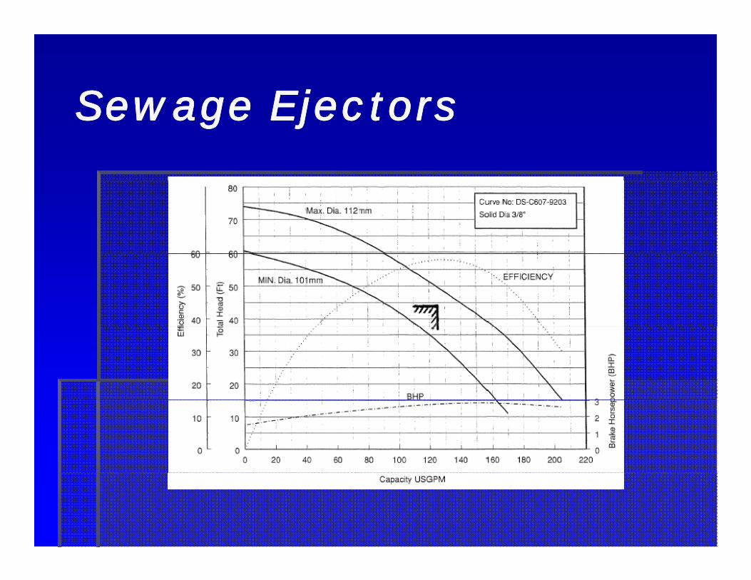
Sewage EjectorsSewage EjectorsSewage EjectorsSewage Ejectors
Pump curves represent the performancePump curves represent the performanceWhen the operating point does not fall on When the operating point does not fall on p g pp g pthe curve …the curve …Trim the impellerTrim the impellerTrim the impellerTrim the impeller
Actual operating pointActual operating point125 gpm125 gpm125 gpm125 gpm44.4 ft head44.4 ft head2.8 HP2.8 HP58% efficient58% efficient

Sewage EjectorsSewage EjectorsSewage EjectorsSewage Ejectors

Sewage EjectorsSewage EjectorsSewage EjectorsSewage Ejectors
Extend the system curveExtend the system curveActual operating pointActual operating pointp g pp g p
125 125 133 gpm133 gpmChanges may affect basin sizingChanges may affect basin sizing
44 444 4 47 ft h d47 ft h d44.4 44.4 47 ft head47 ft headChanges may affect pipe materialChanges may affect pipe material
2 82 8 2 9 HP2 9 HP2.8 2.8 2.9 HP2.9 HPChanges may affect motor selectionChanges may affect motor selection
58% efficient58% efficientChanges may affect economics of operationChanges may affect economics of operation

Sewage EjectorsSewage EjectorsSewage EjectorsSewage Ejectors

Sewage EjectorsSewage EjectorsSewage EjectorsSewage Ejectors
SubmersibleSubmersibleHHxx = pump stop, see = pump stop, see manufacturermanufacturerHHminmin = working volume: Q = working volume: Q in gpm x 60 / number of in gpm x 60 / number of starts per hour (typically Q starts per hour (typically Q x 3 see manufacturer)x 3 see manufacturer)x 3, see manufacturer)x 3, see manufacturer)HHlaglag = 2nd pump delay: = 2nd pump delay: typically 2 in, see typically 2 in, see manufacturermanufacturerHHresres = reserve: typically 2”= reserve: typically 2”Vent must be above inletVent must be above inlet
Sewage EjectorsSewage EjectorsSewage EjectorsSewage Ejectors
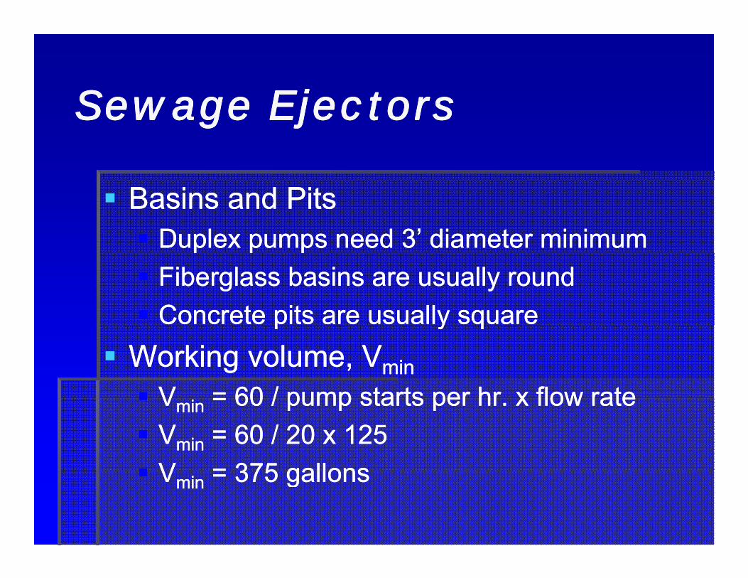
Basins and PitsBasins and PitsDuplex pumps need 3’ diameter minimumDuplex pumps need 3’ diameter minimump p pp p pFiberglass basins are usually roundFiberglass basins are usually roundConcrete pits are usually squareConcrete pits are usually squarep y qp y q
Working volume, VWorking volume, VminminVV = 60 / pump starts per hr x flow rate= 60 / pump starts per hr x flow rateVVminmin = 60 / pump starts per hr. x flow rate= 60 / pump starts per hr. x flow rateVVminmin = 60 / 20 x 125= 60 / 20 x 125VV = 375 gallons= 375 gallonsVVminmin = 375 gallons= 375 gallons

Sewage EjectorsSewage EjectorsSewage EjectorsSewage Ejectors
Working depth, HWorking depth, Hminmin36” x 36” pit36” x 36” pit375 gallons x 0.134 ft375 gallons x 0.134 ft33/gal = 50 ft/gal = 50 ft33gg gg
50 ft50 ft33 / 9 ft/ 9 ft22 = 5.556 ft deep working volume= 5.556 ft deep working volume
Pump stop, HPump stop, Hxx = 4” = 0.333’= 4” = 0.333’Pump lag HPump lag H = 2” = 0 167’= 2” = 0 167’Pump lag, HPump lag, Hlaglag = 2 = 0.167= 2 = 0.167Pump res, HPump res, Hresres = 2” = 0.167’= 2” = 0.167’Invert = 18” = 1.5’Invert = 18” = 1.5’Basin DepthBasin Depth
5.556’ + 0.333” + 0.167’ + 0.167’ + 1.5’5.556’ + 0.333” + 0.167’ + 0.167’ + 1.5’= 7.723 ft deep= 7.723 ft deep 7.723 ft deep 7.723 ft deep

Sewage EjectorsSewage EjectorsSewage EjectorsSewage Ejectors
Each pump requires independentEach pump requires independentCheck ValveCheck ValveGate Valve, check local codes for ball valvesGate Valve, check local codes for ball valves
Locate valves outside of pitsLocate valves outside of pitsValve boxValve boxWall mountedWall mounted
Backwater valves may be required when Backwater valves may be required when combining fixtures at different elevationscombining fixtures at different elevations
Sewage EjectorsSewage EjectorsSewage EjectorsSewage Ejectors
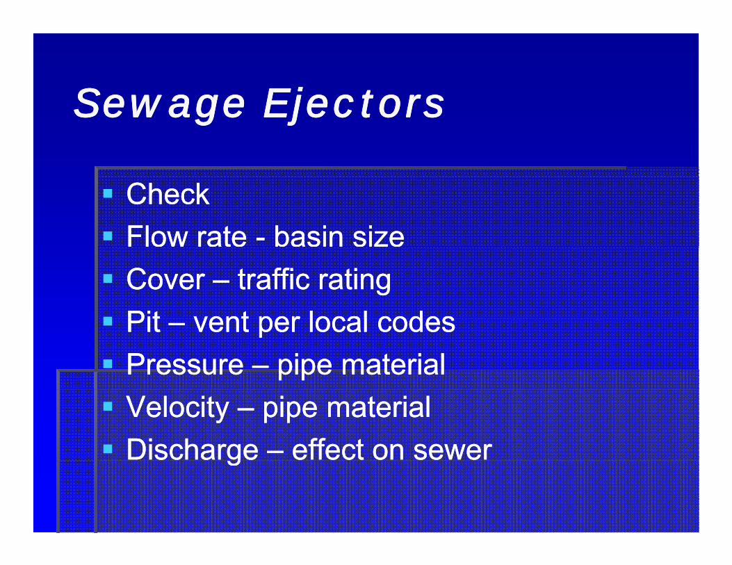
CheckCheckFlow rate Flow rate -- basin sizebasin sizeCover Cover –– traffic ratingtraffic ratingPitPit vent per local codesvent per local codesPit Pit –– vent per local codesvent per local codesPressure Pressure –– pipe materialpipe materialVelocity Velocity –– pipe materialpipe materialDischarge Discharge –– effect on sewereffect on sewergg

Core drill carefullyCore drill carefullyCore drill carefully…Core drill carefully…

BibliographyBibliographyBibliographyBibliography
Alf d St l P EAlf d St l P E Ad d Pl bi T h lAd d Pl bi T h l C t ti I d t PC t ti I d t PAlfred Steele, P.E., Alfred Steele, P.E., Advanced Plumbing TechnologyAdvanced Plumbing Technology, Construction Industry Press, , Construction Industry Press, Elmhurst, IL 1984Elmhurst, IL 1984Alfred Steele, P.E., Alfred Steele, P.E., Engineered Plumbing DesignEngineered Plumbing Design, Second edition, Construction , Second edition, Construction Industry Press, Elmhurst, IL, 1982Industry Press, Elmhurst, IL, 1982American Society of Plumbing EngineersAmerican Society of Plumbing Engineers Sanitary Drainage And Vent PipingSanitary Drainage And Vent PipingAmerican Society of Plumbing Engineers, American Society of Plumbing Engineers, Sanitary Drainage And Vent Piping Sanitary Drainage And Vent Piping SystemsSystems, Chicago, IL, 2006, Chicago, IL, 2006Cast Iron Soil Pipe Institute, Cast Iron Soil Pipe Institute, Cast Iron Soil Pipe & Fittings Specifier’s GuideCast Iron Soil Pipe & Fittings Specifier’s Guide, , Chattanooga, TNChattanooga, TNInternational Association of Plumbing and Mechanical Officials, International Association of Plumbing and Mechanical Officials, Uniform Plumbing Uniform Plumbing C d Ill t t d T i i M lC d Ill t t d T i i M l W l t CA 1997W l t CA 1997Code Illustrated Training ManualCode Illustrated Training Manual, Walnut, CA, 1997, Walnut, CA, 1997International Association of Plumbing and Mechanical Officials, International Association of Plumbing and Mechanical Officials, 2006 Uniform 2006 Uniform Plumbing Code, Plumbing Code, Ontario, CA 2006Ontario, CA 2006International Code Council Inc., International Code Council Inc., 2006 International Plumbing Code2006 International Plumbing Code, Country Club , Country Club Hills IL 2006Hills IL 2006Hills, IL, 2006Hills, IL, 2006Submersible Wastewater Pump Association, Submersible Wastewater Pump Association, Submersible Sewage Pumping Submersible Sewage Pumping Systems (SWPA) HandbookSystems (SWPA) Handbook, Second Edition, Glenview, IL, 1997, Second Edition, Glenview, IL, 1997

QuestionsQuestionsQuestionsQuestions


![Media kit 2010[1].pdf low res..pdf-1](https://static.fdocuments.in/doc/165x107/58f19a9f1a28aba8488b45d9/media-kit-20101pdf-low-respdf-1.jpg)