![1 habit 1[1].pdf](https://static.fdocuments.in/doc/165x107/55cf92cb550346f57b999be7/1-habit-11pdf.jpg)
Euro_IV_BH117L_ABS6_Diagnostic_sys_for_DwBus_080226 (1) (1).pdf
64
Knorr-Bremse Group Knorr-Bremse ABS6 Diagnostic system Knorr-Bremse Korea, April, 2007 Area to fit in a picture - facultative For Daewoo Bus application Ver.1.4
-
Upload
denis-butuci -
Category
Documents
-
view
235 -
download
2
Transcript of Euro_IV_BH117L_ABS6_Diagnostic_sys_for_DwBus_080226 (1) (1).pdf

Knorr-Bremse Group
Knorr-BremseABS6 Diagnostic system
Knorr-Bremse Korea, April, 2007
Area to fit in a picture - facultative
For Daewoo Bus application
Ver.1.4
Knorr-Bremse Group
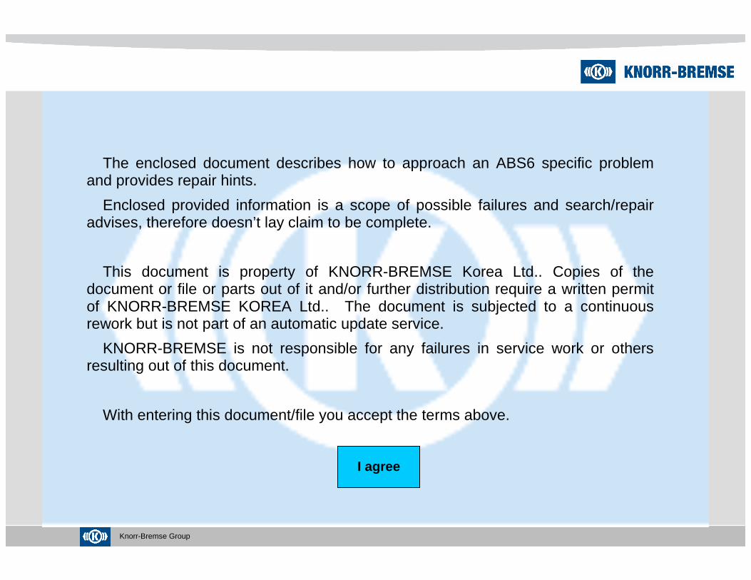
The enclosed document describes how to approach an ABS6 specific problem and provides repair hints.
Enclosed provided information is a scope of possible failures and search/repair advises, therefore doesn’t lay claim to be complete.
This document is property of KNORR-BREMSE Korea Ltd.. Copies of the document or file or parts out of it and/or further distribution require a written permit of KNORR-BREMSE KOREA Ltd.. The document is subjected to a continuous rework but is not part of an automatic update service.
KNORR-BREMSE is not responsible for any failures in service work or others resulting out of this document.
With entering this document/file you accept the terms above.
I agree

Knorr-Bremse Group 3
Feature
Agenda
point 1
point 2
Overview
Troubleshooting and Fault-findingpoint 3
System Componentspoint 4
Wiring Diagramspoint 5
3.1 Blink code 3.2 Fault code list 3.3 PC diagnostics 3.4 Workshop diagnositcs

Knorr-Bremse Group
ABS6 ECU Family Overview
+ Covers the complete range from “basic ABS” to “hig h end drive stability features”
with one modular system family
- STANDARD - a cost optimized ABS system up to 4S/4M
(coverage > 80% of the vehicles)
- PREMIUM - system including configurations up to 6S/6M
and additional functions (ATC, brake diagnostic, et c.)
- ADVANCED - system including configurations up to 6S/4M
with ABS based drive stability
+ Available for cab and frame mounting (Advanced fo r cab only)
+ Available for 12V and 24V power supply
+ Pin compatible ECU family with modular connectors and similar mounting
1. Overview

Knorr-Bremse Group
ABS6 – Design for Global Application of Global Customers
1. Overview

Knorr-Bremse Group
ABS6 – Cab ECU Mounting
2. Feature
P/No : 0 486 107 007 P/No : 0 486 107 105

Knorr-Bremse Group
ABS6 – Modular Connector (Cab-ECU)
2. Feature

Knorr-Bremse Group
ABS6 – Standard System
2. Feature

Knorr-Bremse Group
ABS6 – Premium System
2. Feature

Knorr-Bremse Group
ABS6 – 4 x 2 Vehicles, 4S/4M
2. Feature

Knorr-Bremse Group
Fault DetectionThe ECU continuously monitors the condition of the ABS components while the
vehicle is in use. If the ECU detects any malfuncti on or problem (either with the
brake released or applied) it will switch on the AB S warning lamp and shut down,
either partially or completely, the operation of th e ABS.
Once the ABS warning lamp has been switched on to s ignify that a fault exists in
the system the nature and location of the fault mus t be identified as soon as
possible by one of two methods :
- Use of the Blink Codes
- Use of PC Diagnostics
3. Troubleshooting and Fault-finding
Note: Even a not working ABS (warning lamp “on”) has no i nfluence to the normal brake function, the safety aspect and country speci fic regulations require anImmediate repair work in an authorized workshop !

Knorr-Bremse Group
Using Blink Codes
The ABS warning Lamp is used not only to display th e fact that a fault exists but
also to display blink codes.
The blink code function within the ECU can be used to display two types of blink
code :
- Configuration Blink Codes
showing the system configuration of the ECU program ming
- Fault Blink Codes
giving information on faults detected and stored by the ECU
3. Troubleshooting and Fault-finding

Knorr-Bremse Group
Operation of the Blink Codes Switch
3. Troubleshooting and Fault-finding
Knorr-Bremse Group
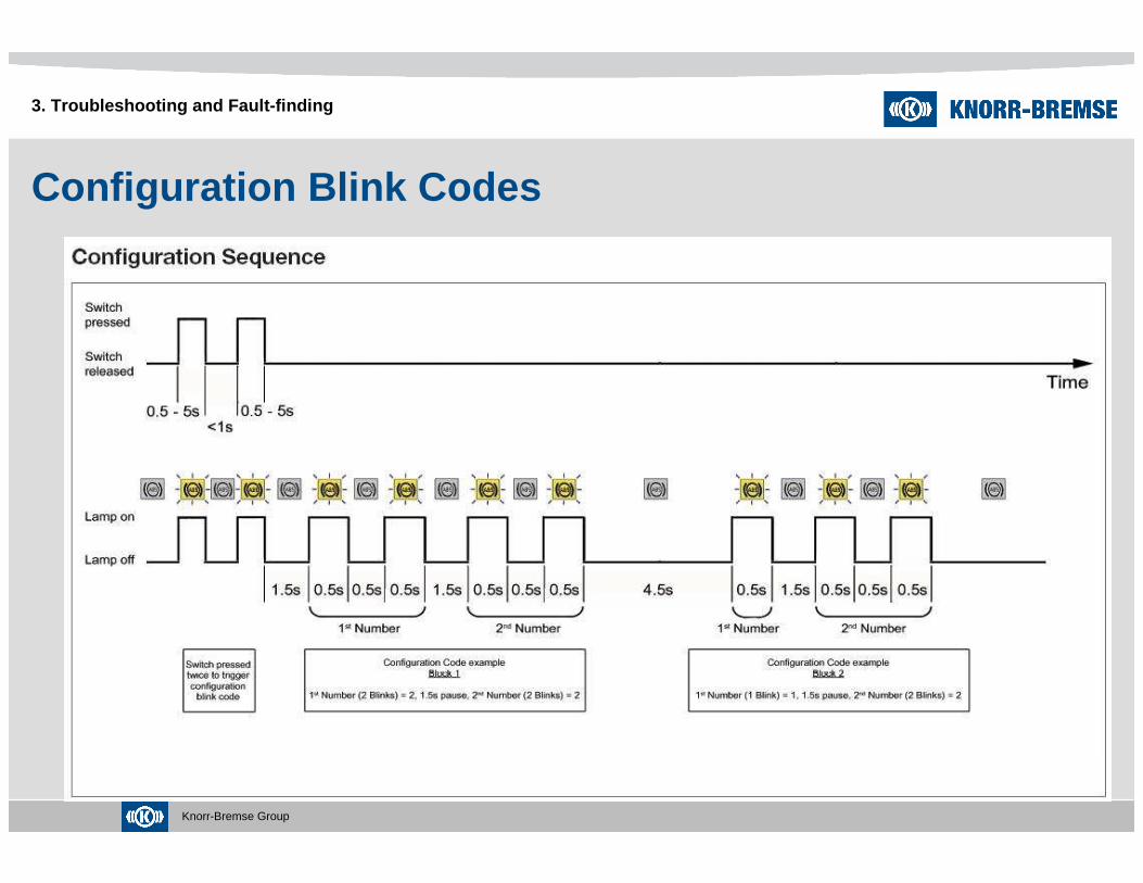
Configuration Blink Codes
3. Troubleshooting and Fault-finding
Knorr-Bremse Group
Configuration Blink Codes
3. Troubleshooting and Fault-finding
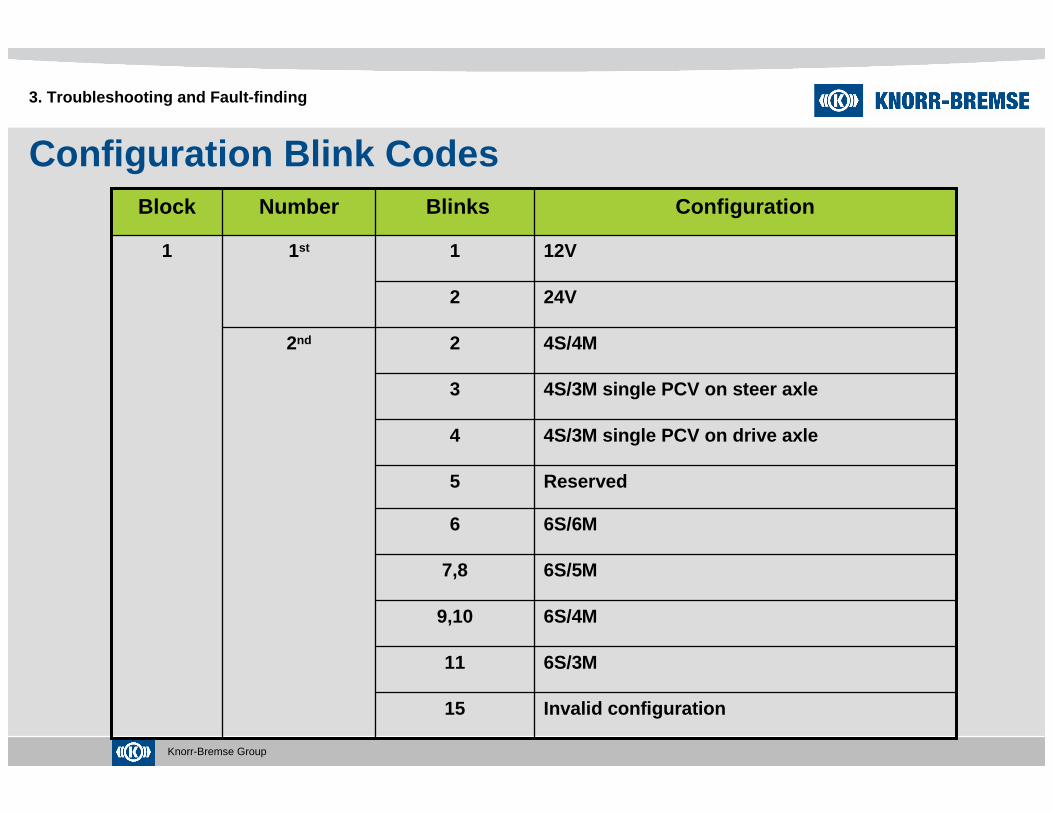
6S/4M9,10
6S/3M11
Invalid configuration15
6S/5M7,8
6S/6M6
Reserved5
4S/3M single PCV on drive axle4
4S/3M single PCV on steer axle3
4S/4M22nd
24V2
12V11st1
ConfigurationBlinksNumberBlock

Knorr-Bremse Group
Configuration Blink Codes
3. Troubleshooting and Fault-finding
2nd
No J1939 engine link, with tcv on drive axle4
with J1939 engine link, with tcv on drive axle5
with J1939 engine link, no tcv on drive axle3
No J1939 engine link, no tcv on drive axle2
with J1939 retarder link, with retarder relay4
No J1939 retarder link, with retarder relay3
With J1939 retarder link, no retarder relay2
No J1939 retarder link, no retarder relay11st2
ConfigurationBlinksNumberBlock
Knorr-Bremse Group
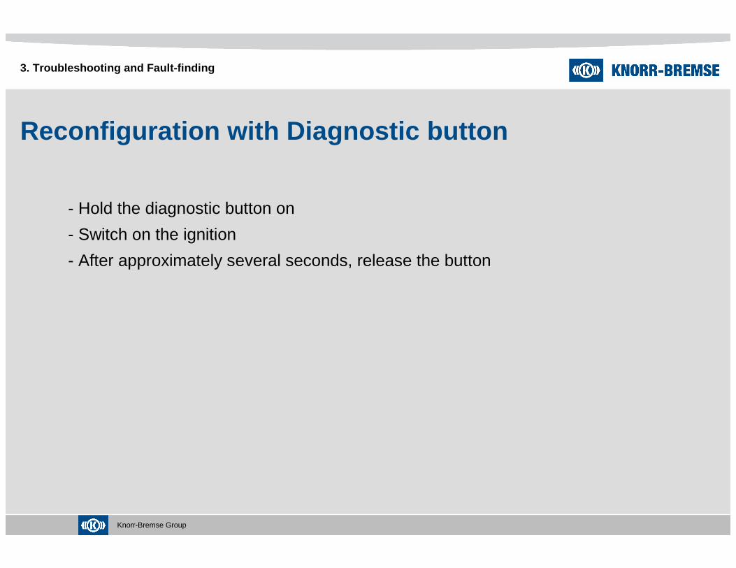
Reconfiguration with Diagnostic button
- Hold the diagnostic button on
- Switch on the ignition
- After approximately several seconds, release the button
3. Troubleshooting and Fault-finding
Knorr-Bremse Group
Configuration Blink Codes
3. Troubleshooting and Fault-finding

Knorr-Bremse Group
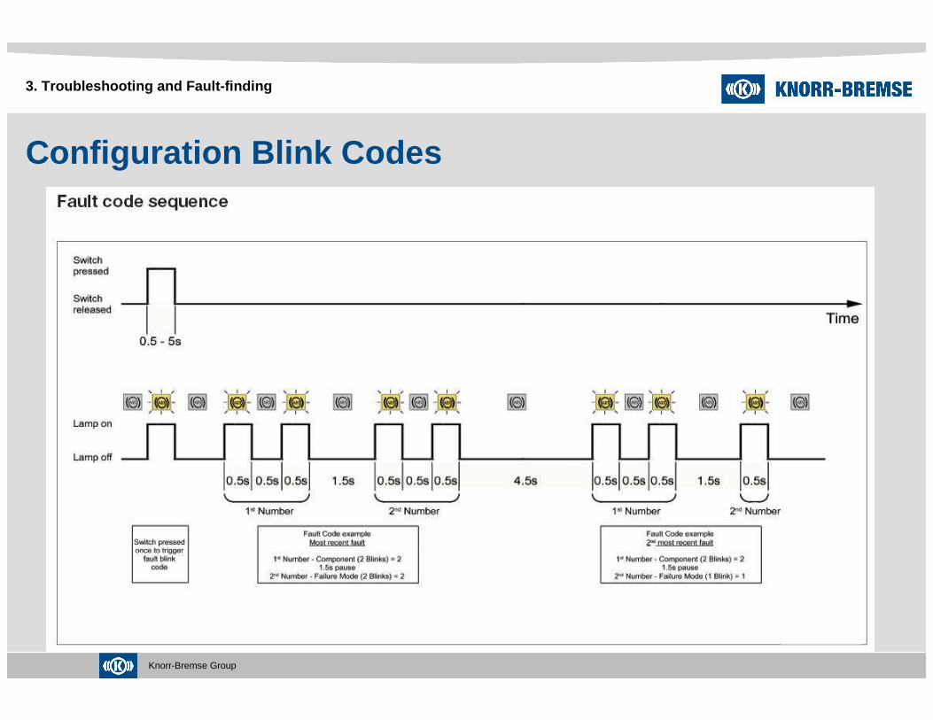
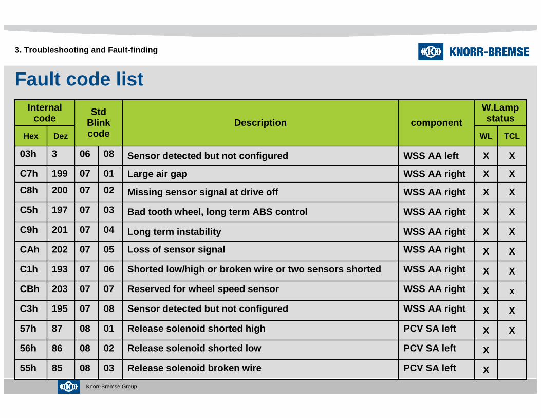
Fault code list
3. Troubleshooting and Fault-finding
XXWSS SA leftShorted low/high or broken wire or two sensors shor ted06026541h
X
X
X
X
X
X
X
X
X
X
WL
W.Lampstatus
WSS SA right
WSS SA right
WSS SA right
WSS SA right
WSS SA left
WSS SA left
WSS SA left
WSS SA left
WSS SA left
WSS SA left
component
XLong term instability04027349h
xLong term instability040313789h
XBad tooth wheel, long term ABS control030313385h
XMissing sensor signal at drive off020313688h
XLarge air gap 010313587h
XReserved for wheel speed sensor0702754Bh
XLoss of sensor signal0502744Ah
XBad tooth wheel, long term ABS control03026945h
xMissing sensor signal at drive off02027248h
xLarge air gap 01027147h
No failure0101000h
TCLDezHex
DescriptionStd
Blink code
Internal code

Knorr-Bremse Group
Fault code list
3. Troubleshooting and Fault-finding
XXWSS DA leftLong term instability0404169A9h
X
X
X
X
X
X
X
X
X
X
X
WL
W.Lampstatus
WSS DA right
WSS DA right
WSS DA left
WSS DA left
WSS DA left
WSS DA left
WSS DA left
WSS DA left
WSS SA right
WSS SA right
WSS SA right
component
XMissing sensor signal at drive off0204168A8h
xMissing sensor signal at drive off020510468h
XLarge air gap 010510367h
XReserved for wheel speed sensor0704171ABh
XShorted low/high or broken wire or two sensors shor ted0604161A1h
XLoss of sensor signal0504170AAh
XBad tooth wheel, long term ABS control0304165A5h
XLarge air gap 0104167A7h
xReserved for wheel speed sensor07031398Bh
xShorted low/high or broken wire or two sensors shor ted060312981h
XLoss of sensor signal05031388Ah
TCLDezHex
DescriptionStd
Blink code
Internal code

Knorr-Bremse Group
Fault code list
3. Troubleshooting and Fault-finding
XXWSS AA leftMissing sensor signal at drive off0206808h
X
X
X
X
X
X
X
X
X
X
X
WL
W.Lampstatus
WSS AA left
WSS AA left
WSS AA left
WSS AA left
WSS AA left
WSS AA left
WSS DA right
WSS DA right
WSS DA right
WSS DA right
WSS DA right
component
XReserved for wheel speed sensor07051076Bh
xReserved for wheel speed sensor0706110Bh
XShorted low/high or broken wire or two sensors shor ted0606101h
XLoss of sensor signal0506100Ah
XLong term instability0406909h
XBad tooth wheel, long term ABS control0306505h
XLarge air gap 0106707h
XShorted low/high or broken wire or two sensors shor ted06059761h
xLoss of sensor signal05051066Ah
xLong term instability040510569h
XBad tooth wheel, long term ABS control030510165h
TCLDezHex
DescriptionStd
Blink code
Internal code
Knorr-Bremse Group
Fault code list
3. Troubleshooting and Fault-finding
XXWSS AA rightShorted low/high or broken wire or two sensors shor ted0607193C1h
X
X
X
X
X
X
X
X
X
X
X
WL
W.Lampstatus
PCV SA left
PCV SA left
PCV SA left
WSS AA right
WSS AA right
WSS AA right
WSS AA right
WSS AA right
WSS AA right
WSS AA right
WSS AA left
component
XLong term instability0407201C9h
Release solenoid broken wire03088555h
Release solenoid shorted low02088656h
XRelease solenoid shorted high01088757h
XSensor detected but not configured0807195C3h
xReserved for wheel speed sensor0707203CBh
XLoss of sensor signal0507202CAh
XBad tooth wheel, long term ABS control0307197C5h
XMissing sensor signal at drive off0207200C8h
XLarge air gap 0107199C7h
XSensor detected but not configured0806303h
TCLDezHex
DescriptionStd
Blink code
Internal code
Knorr-Bremse Group
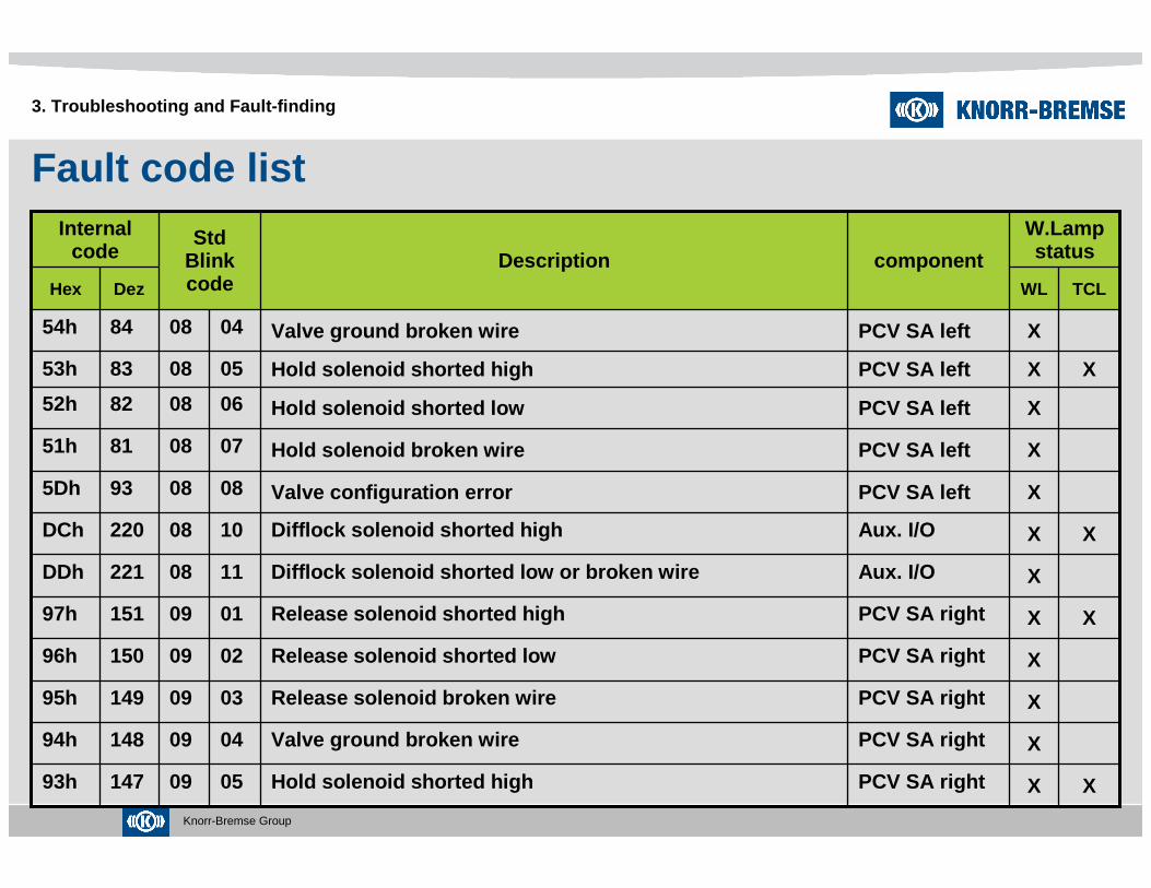
Fault code list
3. Troubleshooting and Fault-finding
XAux. I/ODifflock solenoid shorted low or broken wire1108221DDh
X
X
X
X
X
X
X
X
X
X
X
WL
W.Lampstatus
PCV SA right
PCV SA right
PCV SA right
PCV SA right
PCV SA right
Aux. I/O
PCV SA left
PCV SA left
PCV SA left
PCV SA left
PCV SA left
component
Valve configuration error0808935Dh
XHold solenoid shorted high050914793h
Valve ground broken wire040914894h
Release solenoid broken wire030914995h
Release solenoid shorted low020915096h
XRelease solenoid shorted high010915197h
XDifflock solenoid shorted high1008220DCh
Hold solenoid broken wire07088151h
Hold solenoid shorted low06088252h
XHold solenoid shorted high05088353h
Valve ground broken wire04088454h
TCLDezHex
DescriptionStd
Blink code
Internal code

Knorr-Bremse Group
Fault code list
3. Troubleshooting and Fault-finding
XXPCV DA leftValve ground broken wire0410180B4h
X
X
X
X
X
X
X
X
X
X
X
WL
W.Lampstatus
PCV
PCV DA left
PCV DA left
PCV DA left
PCV DA left
PCV DA left
PCV DA left
PCV DA left
PCV SA right
PCV SA right
PCV SA right
component
XRelease solenoid shorted low0210182B6h
XValve ground or solenoid shunt to supply voltage10104129h
XValve configuration error0810189BDh
XHold solenoid broken wire0710177B1h
XHold solenoid shorted low0610178B2h
XHold solenoid shorted high0510179B3h
XRelease solenoid broken wire0310181B5h
XRelease solenoid shorted high0110183B7h
Valve configuration error08091579Dh
Hold solenoid broken wire070914591h
Hold solenoid shorted low060914692h
TCLDezHex
DescriptionStd
Blink code
Internal code

Knorr-Bremse Group
Fault code list
3. Troubleshooting and Fault-finding
XXPCV DA rightHold solenoid shorted low061111472h
X
X
X
X
X
X
X
X
X
X
X
WL
W.Lampstatus
PCV AA left
PCV AA left
PCV AA left
PCV DA right
PCV DA right
PCV DA right
PCV DA right
PCV DA right
PCV DA right
PCV DA right
PCV
component
XValve ground broken wire041111674h
XRelease solenoid broken wire0312229E5h
XRelease solenoid shorted low0212230E6h
XRelease solenoid shorted high0112231E7h
XValve configuration error08111257Dh
XHold solenoid broken wire071111371h
XHold solenoid shorted high051111573h
XRelease solenoid broken wire031111775h
XRelease solenoid shorted low021111876h
XRelease solenoid shorted high011111977h
XValve GND or sol. shunt to GND or int.GND SW defecti ve1110422Ah
TCLDezHex
DescriptionStd
Blink code
Internal code
Knorr-Bremse Group
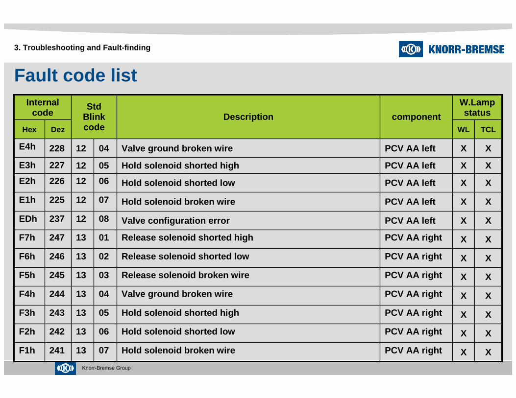
Fault code list
3. Troubleshooting and Fault-finding
XXPCV AA rightRelease solenoid shorted low0213246F6h
X
X
X
X
X
X
X
X
X
X
X
WL
W.Lampstatus
PCV AA right
PCV AA right
PCV AA right
PCV AA right
PCV AA right
PCV AA right
PCV AA left
PCV AA left
PCV AA left
PCV AA left
PCV AA left
component
XValve configuration error0812237EDh
XHold solenoid broken wire0713241F1h
XHold solenoid shorted low0613242F2h
XHold solenoid shorted high0513243F3h
XValve ground broken wire0413244F4h
XRelease solenoid broken wire0313245F5h
XRelease solenoid shorted high0113247F7h
XHold solenoid broken wire0712225E1h
XHold solenoid shorted low0612226E2h
XHold solenoid shorted high0512227E3h
XValve ground broken wire0412228E4h
TCLDezHex
DescriptionStd
Blink code
Internal code

Knorr-Bremse Group
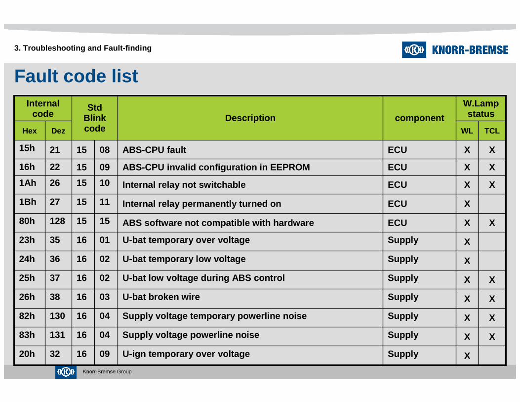
Fault code list
3. Troubleshooting and Fault-finding
XXECUABS-CPU fault02151711h
X
X
X
X
X
X
X
X
X
WL
W.Lampstatus
ECU
ECU
ECU
ECU
ECU
ECU
TCV DA
TCV DA
TCV DA
TCV DA
PCV AA right
component
TC valve configuration error0814613Dh
XABS-CPU fault07151812h
XABS-CPU fault06152014h
XABS-CPU fault05151913h
XABS-CPU EEPROM not programmable04152418h
XABS-CPU EEPROM data error03152317h
XABS-CPU fault01151610h
XTC solenoid broken wire0714583Ah
XTC solenoid shorted low0614593Bh
XTC solenoid shorted high0514603Ch
XValve configuration error0813253FDh
TCLDezHex
DescriptionStd
Blink code
Internal code
Knorr-Bremse Group
Fault code list
3. Troubleshooting and Fault-finding
XSupplyU-bat temporary low voltage02163624h
X
X
X
X
X
X
X
X
X
X
X
WL
W.Lampstatus
Supply
Supply
Supply
Supply
Supply
Supply
ECU
ECU
ECU
ECU
ECU
component
XABS software not compatible with hardware151512880h
U-ign temporary over voltage09163220h
XSupply voltage powerline noise041613183h
XSupply voltage temporary powerline noise041613082h
XU-bat broken wire03163826h
XU-bat low voltage during ABS control02163725h
U-bat temporary over voltage01163523h
Internal relay permanently turned on 1115271Bh
XInternal relay not switchable1015261Ah
XABS-CPU invalid configuration in EEPROM09152216h
XABS-CPU fault08152115h
TCLDezHex
DescriptionStd
Blink code
Internal code
Knorr-Bremse Group
Fault code list
3. Troubleshooting and Fault-finding
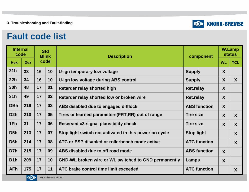
XXTire sizeReserved c3-signal plausibility check0617311Fh
X
X
X
X
X
X
X
X
WL
W.Lampstatus
ATC function
Lamps
ABS function
ATC function
Stop light
Tire size
ABS function
Ret.relay
Ret.relay
Supply
Supply
component
ABS disabled due to engaged difflock0317219DBh
XATC brake control time limit exceeded1117175AFh
GND-WL broken wire or WL switched to GND permanentl y1017209D1h
ABS disabled due to off road mode0917215D7h
XATC or ESP disabled or rollerbench mode active0817214D6h
XStop light switch not activated in this power on cy cle0717213D5h
XTires or learned parameters(FRT,RR) out of range0517210D2h
Retarder relay shorted low or broken wire02174931h
Retarder relay shorted high01174830h
XU-ign low voltage during ABS control10163422h
U-ign temporary low voltage10163321h
TCLDezHex
DescriptionStd
Blink code
Internal code

Knorr-Bremse Group
Fault code list
3. Troubleshooting and Fault-finding
XJ1939/IESTimeout or invalid data on ETC1..2 (J1939) / INS,EP S (IES)06185436h
X
X
X
X
X
WL
W.Lampstatus
J1939/IES
J1939/IES
J1939/IES
Stop light
WSS
WSS
component
Timeout or invalid data on ERC1 (J1939) / FMR2 (IES )04185234h
All others reserved or unused
XTimeout or invalid data on EEC1..3 (J1939) / FMR1.. 3 (IES)05185335h
XJ1939 or IES CAN bus off detected03185133h
Stop light switch defective1417216D8h
XWSS mixed up1317212D4h
XWSS failure in previous power on cycle1217208D0h
TCLDezHex
DescriptionStd
Blink code
Internal code
Note: When WSS or Airgap related fault occurred, the warni ng lamp won’t go off even after the cause is corrected. Fault code D0h will be erase automatically after ECU get valid WSS signal in several driving.
Knorr-Bremse Group
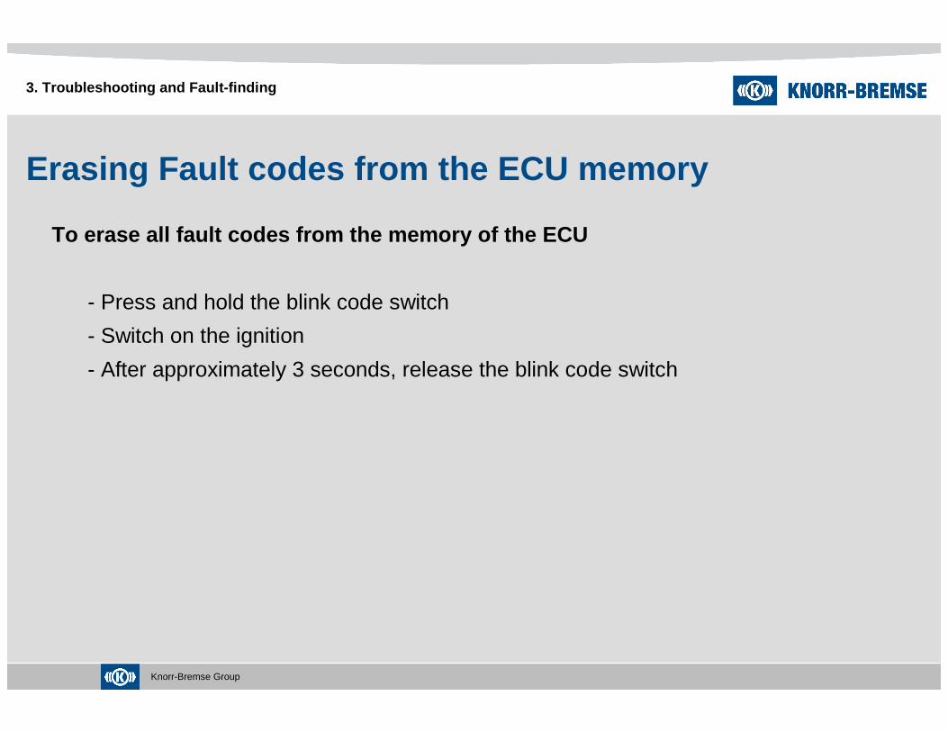
Erasing Fault codes from the ECU memory
To erase all fault codes from the memory of the ECU
- Press and hold the blink code switch
- Switch on the ignition
- After approximately 3 seconds, release the blink code switch
3. Troubleshooting and Fault-finding

Knorr-Bremse Group
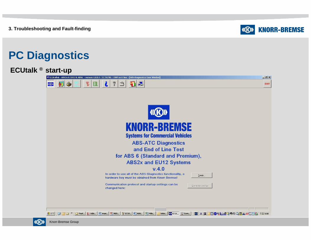
PC Diagnostics
A computer based program ECUtalk ® – ABS Diagnostics is available and provides
several functions :
- Assists workshop diagnosis of ABS problems.
- Enables system check after servicing of the ABS system
- Includes a database to enable storage and retrieval of information
relating to customer, vehicle and test results
- Knowledge base covering the function and servicing advice for ABS systems
and their components, wiring diagrams and a software manual for the program
3. Troubleshooting and Fault-finding

Knorr-Bremse Group
PC DiagnosticsSystem Requirements
3. Troubleshooting and Fault-finding
The required operating system should follow this specification :
Pentium processor or higher,
100 Mbytes of HDD
Windows 98 and/or NT4 with service pack 4 or higher
800x600 display resolution
For optimum performance the following system specification is recommended :
1024x768 display resolution (or higher)
Pentium Ⅱ processor
Laser printer
Windows 2000 or XP
UDIF software
Version 1.15r or later is a must
Knorr-Bremse Group
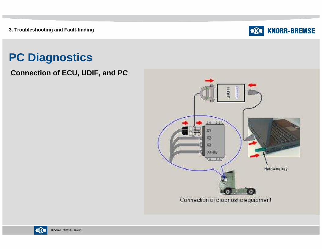
PC DiagnosticsConnection of ECU, UDIF, and PC
3. Troubleshooting and Fault-finding
Knorr-Bremse Group 35
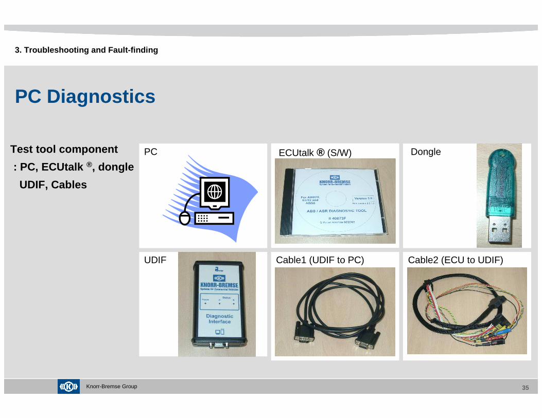
PC Dongle
Cable1 (UDIF to PC) Cable2 (ECU to UDIF)
PC Diagnostics
Test tool component
: PC, ECUtalk ®, dongle
UDIF, Cables
UDIF
ECUtalk ® (S/W)
3. Troubleshooting and Fault-finding
Knorr-Bremse Group
PC DiagnosticsECUtalk ® start-up
3. Troubleshooting and Fault-finding

Knorr-Bremse Group
PC DiagnosticsECUtalk ® EOL test
3. Troubleshooting and Fault-finding

Knorr-Bremse Group
PC DiagnosticsECUtalk ® Workshop test
3. Troubleshooting and Fault-finding

Knorr-Bremse Group
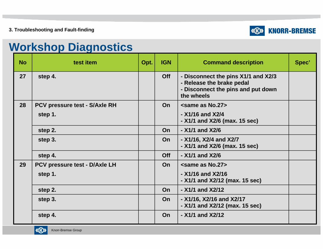
Workshop Diagnostics
3. Troubleshooting and Fault-finding
21-29 V- Measure the voltage between X1-1 and X1-16
OnPower supply of PCV4
SW on- Disconnect X1-1 and X1-17OnOpt.Retarder relay -switch on6
SW off- Switch the RET on.- Connect X1-1 and X1-17
OnOpt.Retarder relay -switch off5
21-29 V- Measure the voltage between X1-1 and X1-3
OnPower supply of ECU3
≤3Ω- Remove fuse for permanent vehicle supply, replace fuse after test step- Connect pin X1-1 to battery ground
OffGround for ECU2
≤3Ω- Remove fuse for permanent vehicle supply, replace fuse after test step- Connect pin X1-12 to battery ground
OffGround for Warning lamp1
- Disconnect ECU and UDIF from the vehicle peripheries
OffPreparation for test0
Spec’Command descriptionIGNOpt.test itemNo

Knorr-Bremse Group
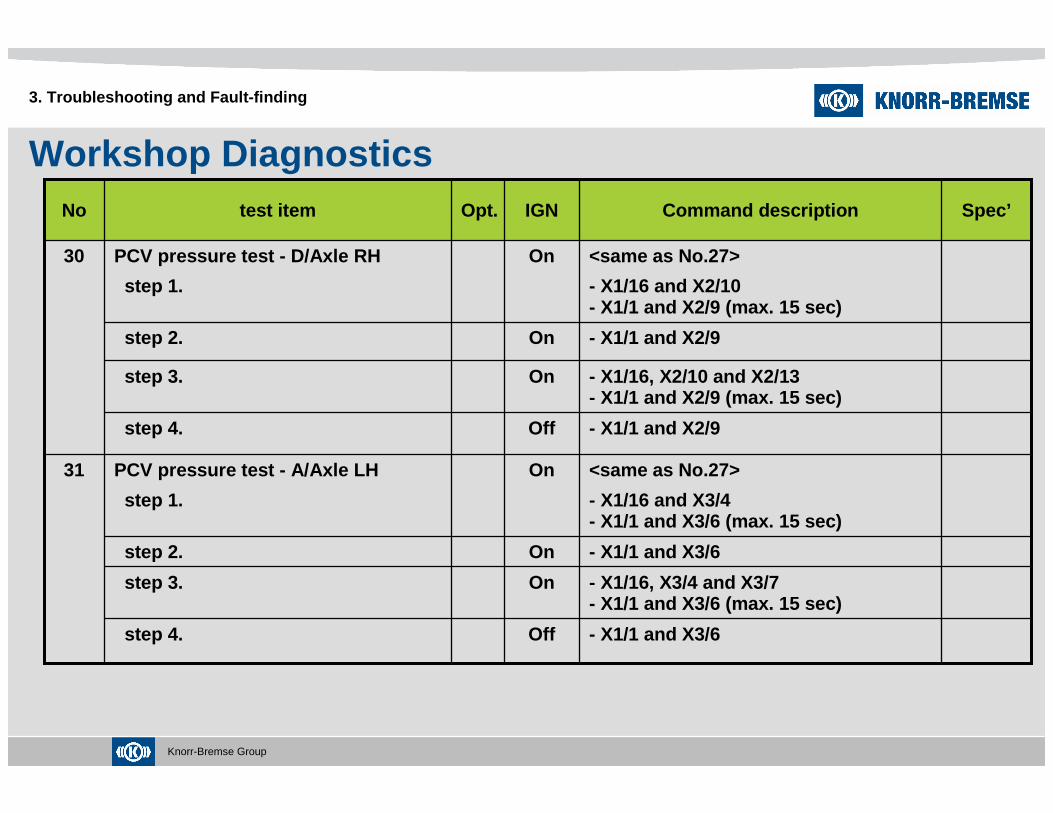
Workshop Diagnostics
3. Troubleshooting and Fault-finding
14-21Ω- Measure the resistance between X2-12 and X2-16
OffResistance of PCV - inlet valve -D/Axle LH
13
≤4.5Ω- Remove fuse for permanent vehicle supply, replace fuse after test step- Switch the ABS off-road switch on- Measure the resistance between X1-1 and X3-1
OffOpt.ABS off-road switch - switch on7
14-21Ω- Measure the resistance between X2-3 and X2-2
OffResistance of PCV - outlet valve -S/Axle LH
10
14-21Ω- Measure the resistance between X2-12 and X2-17
OffResistance of PCV - outlet valve -D/Axle LH
14
14-21Ω- Measure the resistance between X2-6 and X2-7
OffResistance of PCV - outlet valve -S/Axle RH
12
14-21Ω- Measure the resistance between X2-6 and X2-4
OffResistance of PCV - inlet valve -S/Axle RH
11
14-21Ω- Measure the resistance between X2-3 and X2-1
OffResistance of PCV - inlet valve -S/Axle LH
9
≥1 MΩ- Switch the ABS off-road switch off- Measure the resistance between X1-1 and X3-1
OffOpt.ABS off-road switch - switch off8
Spec’Command descriptionIGNOpt.test itemNo

Knorr-Bremse Group
Workshop Diagnostics
3. Troubleshooting and Fault-finding
0.8 - 2.2 kΩ
- Measure the resistance between X2-11 and X2-14
OffResistance of Speed sensor - S/Axle RH
22
0.8 - 2.2 kΩ
- Measure the resistance between X2-5 and X2-8
OffResistance of Speed sensor - S/Axle LH
21
14-21Ω- Measure the resistance between X2-9 and X2-10
OffResistance of PCV - inlet valve -D/Axle RH
15
14-21Ω- Measure the resistance between X3-6 and X3-7
OffResistance of PCV - outlet valve -A/Axle LH
18
0.8 - 2.2 kΩ
- Measure the resistance between X2-15 and X2-18
OffResistance of Speed sensor - D/Axle LH
23
14-21Ω- Measure the resistance between X3-9 and X3-13
OffResistance of PCV - outlet valve -A/Axle RH
20
14-21Ω- Measure the resistance between X3-9 and X3-10
OffResistance of PCV - inlet valve -A/Axle RH
19
14-21Ω- Measure the resistance between X3-6 and X3-4
OffResistance of PCV - inlet valve -A/Axle LH
17
14-21Ω- Measure the resistance between X2-9 and X2-13
OffResistance of PCV - outlet valve -D/Axle RH
16
Spec’Command descriptionIGNOpt.test itemNo

Knorr-Bremse Group
Workshop Diagnostics
3. Troubleshooting and Fault-finding
0.8 - 2.2 kΩ
- Measure the resistance between X1-10 and X1-11
OffResistance of Speed sensor - D/Axle RH
24
0.8 - 2.2 kΩ
- Measure the resistance between X3-11 and X3-14
OffResistance of Speed sensor - A/Axle LH
25
0.8 - 2.2 kΩ
- Measure the resistance between X3-12 and X3-15
OffResistance of Speed sensor - A/Axle RH
26
The wheels on SAare freely rotating
- Lift the Steer axle- Connect the pins X1/16 and X2/1- Connect the pins X1/1 and X2/3 (max. 15 sec)- Push the brake pedal- Turn the wheels and check the result
OnPCV pressure test - S/Axle LH
step 1.
27
are freely rotating
- Keep brake pushed- Connect the pins X1/16, X2/1 and X2/2- Connect the pins X1/1 and X2/3 (max. 15 sec)- Turn the wheels and check the result
Onstep 3.
are braked
- Keep brake pushed- Disconnect the pins X1/1 and X2/3
Onstep 2.
Spec’Command descriptionIGNOpt.test itemNo
Knorr-Bremse Group
Workshop Diagnostics
3. Troubleshooting and Fault-finding
- X1/16, X2/16 and X2/17- X1/1 and X2/12 (max. 15 sec)
Onstep 3.
- X1/1 and X2/12Onstep 2.
<same as No.27>
- X1/16 and X2/16- X1/1 and X2/12 (max. 15 sec)
OnPCV pressure test - D/Axle LH
step 1.
29
- X1/1 and X2/6Offstep 4.
- X1/16, X2/4 and X2/7- X1/1 and X2/6 (max. 15 sec)
Onstep 3.
- Disconnect the pins X1/1 and X2/3- Release the brake pedal- Disconnect the pins and put down the wheels
Offstep 4.27
<same as No.27>
- X1/16 and X2/4- X1/1 and X2/6 (max. 15 sec)
OnPCV pressure test - S/Axle RH
step 1.
28
- X1/1 and X2/12Onstep 4.
- X1/1 and X2/6Onstep 2.
Spec’Command descriptionIGNOpt.test itemNo
Knorr-Bremse Group
Workshop Diagnostics
3. Troubleshooting and Fault-finding
- X1/16, X3/4 and X3/7- X1/1 and X3/6 (max. 15 sec)
Onstep 3.
- X1/1 and X3/6Onstep 2.
<same as No.27>
- X1/16 and X3/4- X1/1 and X3/6 (max. 15 sec)
OnPCV pressure test - A/Axle LH
step 1.
31
- X1/1 and X2/9Offstep 4.
<same as No.27>
- X1/16 and X2/10- X1/1 and X2/9 (max. 15 sec)
OnPCV pressure test - D/Axle RH
step 1.
30
- X1/1 and X2/9Onstep 2.
- X1/1 and X3/6Offstep 4.
- X1/16, X2/10 and X2/13- X1/1 and X2/9 (max. 15 sec)
Onstep 3.
Spec’Command descriptionIGNOpt.test itemNo
Knorr-Bremse Group
Workshop Diagnostics
3. Troubleshooting and Fault-finding
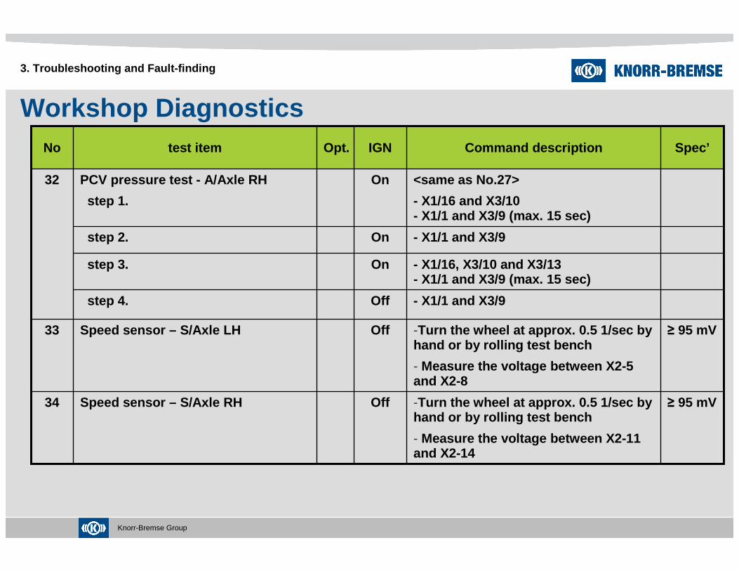
≥ 95 mV-Turn the wheel at approx. 0.5 1/sec by hand or by rolling test bench
- Measure the voltage between X2-11 and X2-14
OffSpeed sensor – S/Axle RH34
≥ 95 mV-Turn the wheel at approx. 0.5 1/sec by hand or by rolling test bench
- Measure the voltage between X2-5 and X2-8
OffSpeed sensor – S/Axle LH33
- X1/1 and X3/9Offstep 4.
<same as No.27>
- X1/16 and X3/10- X1/1 and X3/9 (max. 15 sec)
OnPCV pressure test - A/Axle RH
step 1.
32
- X1/1 and X3/9Onstep 2.
- X1/16, X3/10 and X3/13- X1/1 and X3/9 (max. 15 sec)
Onstep 3.
Spec’Command descriptionIGNOpt.test itemNo

Knorr-Bremse Group
Workshop Diagnostics
3. Troubleshooting and Fault-finding
≥ 95 mV-Turn the wheel at approx. 0.5 1/sec by hand or by rolling test bench
- Measure the voltage between X3-12 and X3-15
OffSpeed sensor – A/Axle RH38
≥ 95 mV-Turn the wheel at approx. 0.5 1/sec by hand or by rolling test bench
- Measure the voltage between X2-15 and X2-18
OffSpeed sensor – D/Axle LH35
≥ 95 mV-Turn the wheel at approx. 0.5 1/sec by hand or by rolling test bench
- Measure the voltage between X1-10 and X1-11
OffSpeed sensor – S/Axle RH36
≥ 95 mV-Turn the wheel at approx. 0.5 1/sec by hand or by rolling test bench
- Measure the voltage between X3-11 and X3-14
OffSpeed sensor – A/Axle LH37
Spec’Command descriptionIGNOpt.test itemNo

Knorr-Bremse Group
Workshop Diagnostics
3. Troubleshooting and Fault-finding
> 30 kΩ-Measure the resistance between X2-8 and X1-3
OffSpeed sensor up to Ubatt - S/Axle LH
45
> 30 kΩ-Measure the resistance between X2-14 and X1-3
OffSpeed sensor up to Ubatt - S/Axle RH
46
> 30 kΩ-Measure the resistance between X2-11 and X1-1
OffSpeed sensor up to GND - S/Axle RH40
> 30 kΩ-Measure the resistance between X2-15 and X1-1
OffSpeed sensor up to GND - D/Axle LH41
> 30 kΩ-Measure the resistance between X1-10 and X1-1
OffSpeed sensor up to GND - D/Axle RH42
> 30 kΩ-Measure the resistance between X3-11 and X1-1
OffSpeed sensor up to GND - A/Axle LH43
> 30 kΩ-Measure the resistance between X3-12 and X1-1
OffSpeed sensor up to GND - A/Axle RH44
> 30 kΩ-Measure the resistance between X2-5 and X1-1
OffSpeed sensor up to GND - S/Axle LH39
> 30 kΩ-Measure the resistance between X2-18 and X1-3
OffSpeed sensor up to Ubatt - D/Axle LH
47
Spec’Command descriptionIGNOpt.test itemNo

Knorr-Bremse Group
Workshop Diagnostics
3. Troubleshooting and Fault-finding
> 30 kΩ-Measure the resistance between X3-14 and X1-3
OffSpeed sensor up to Ubatt - A/Axle LH
49
> 30 kΩ-Measure the resistance between X3-15 and X1-3
OffSpeed sensor up to Ubatt - A/Axle RH
50
≤1Ω-Connect DIAL and DIAK pins in diag. connector
-Measure the resistance between X1-13 and X1-14
OffOpt.DIAK and DIAL51
21-29 V- Push brake pedal- Check the proc result- Release the brake pedal
- Measure the voltage between X1-9 and X1-1
OnStop light switch52
32-42 Ω-Measure the resistance between X1-4 and X1-5
OffInternal resistance of ATC valve53
> 30 kΩ-Measure the resistance between X1-11 and X1-3
OffSpeed sensor up to Ubatt - D/Axle RH
48
Spec’Command descriptionIGNOpt.test itemNo

Knorr-Bremse Group
Workshop Diagnostics
3. Troubleshooting and Fault-finding
The wheels L and Ron DAare braked
- Connect the pins X1/4 and X1/1- Connect the pins X1/5 and X1/16
OnPressure test of ATC valve
step 1
54
are freely rotating
- Disconnect the pinsOnstep 2
Spec’Command descriptionIGNOpt.test itemNo
Knorr-Bremse Group
System componentsECU
4. System components
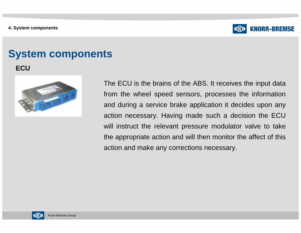
The ECU is the brains of the ABS. It receives the input data
from the wheel speed sensors, processes the information
and during a service brake application it decides upon any
action necessary. Having made such a decision the ECU
will instruct the relevant pressure modulator valve to take
the appropriate action and will then monitor the affect of this
action and make any corrections necessary.
Knorr-Bremse Group
System componentsABS Warning Lamp
4. System components
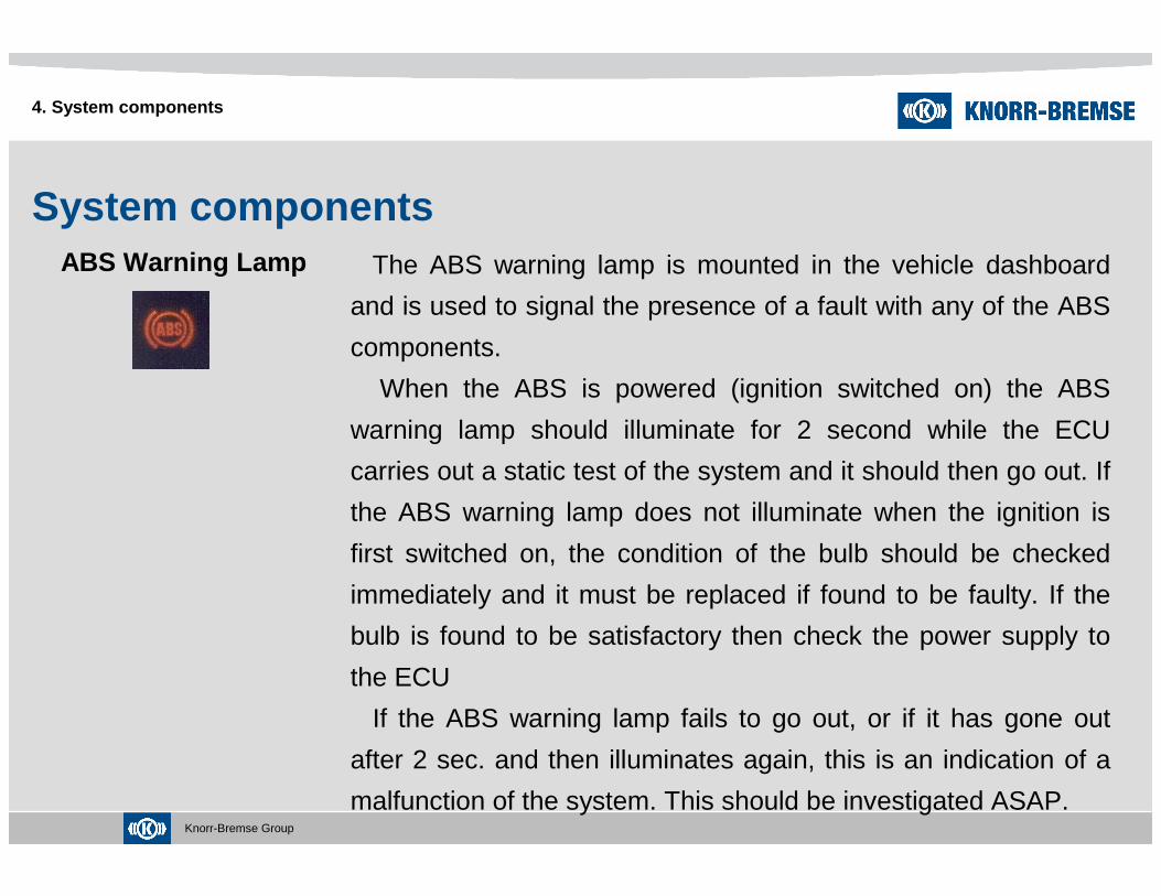
The ABS warning lamp is mounted in the vehicle dashboard
and is used to signal the presence of a fault with any of the ABS
components.
When the ABS is powered (ignition switched on) the ABS
warning lamp should illuminate for 2 second while the ECU
carries out a static test of the system and it should then go out. If
the ABS warning lamp does not illuminate when the ignition is
first switched on, the condition of the bulb should be checked
immediately and it must be replaced if found to be faulty. If the
bulb is found to be satisfactory then check the power supply to
the ECU
If the ABS warning lamp fails to go out, or if it has gone out
after 2 sec. and then illuminates again, this is an indication of a
malfunction of the system. This should be investigated ASAP.

Knorr-Bremse Group
System componentsSensing Ring
4. System components
The sensing ring is a toothed ring rigidly mounted to the
axle end so that it rotates with the wheel.
The sensing ring rotates relative to the wheel speed
sensor, which in turn provides a sinusoidal electrical signal
to the ECU. This signal can be used to measure the
rotational speed of the wheel.
* If any of the teeth become chipped, then the ECU will recognize that the signal
received from WSS is of poor quality.
Knorr-Bremse Group
System componentsWheel Speed sensor
4. System components
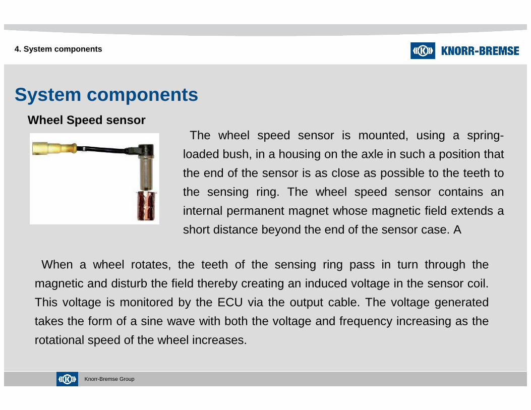
The wheel speed sensor is mounted, using a spring-
loaded bush, in a housing on the axle in such a position that
the end of the sensor is as close as possible to the teeth to
the sensing ring. The wheel speed sensor contains an
internal permanent magnet whose magnetic field extends a
short distance beyond the end of the sensor case. A
When a wheel rotates, the teeth of the sensing ring pass in turn through the
magnetic and disturb the field thereby creating an induced voltage in the sensor coil.
This voltage is monitored by the ECU via the output cable. The voltage generated
takes the form of a sine wave with both the voltage and frequency increasing as the
rotational speed of the wheel increases.
Knorr-Bremse Group
System componentsWheel Speed sensor
4. System components
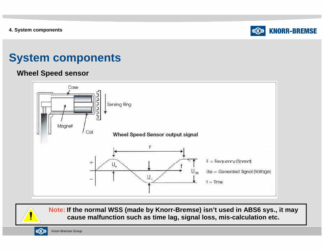
Note: If the normal WSS (made by Knorr-Bremse) isn’t used in ABS6 sys., it may cause malfunction such as time lag, signal loss, mi s-calculation etc.
Knorr-Bremse Group 55
4. System components
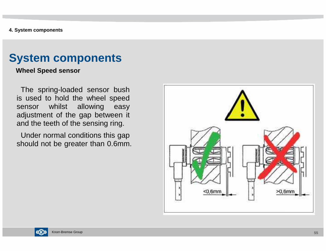
System componentsWheel Speed sensor
The spring-loaded sensor bush is used to hold the wheel speed sensor whilst allowing easy adjustment of the gap between it and the teeth of the sensing ring.
Under normal conditions this gap should not be greater than 0.6mm.

Knorr-Bremse Group 56
4. System components
System componentsWheel Speed sensor
The wheel speed sensor and its extension cable can be checked with multi-meter.

Knorr-Bremse Group
System componentsSensor Extension
Cable
4. System components
The sensor extension cable is used to connect the wheel
speed sensor to the ECU. The connector on the wheel speed
sensor output cable is designed to join with the sensor extension
cable and provide a weatherproof seal. It is therefore important
that the connectors are inserted correctly and are fully engaged.
If a sensor extension cable is replaced and it is secured with
cable ties then they should never by tightened excessively as the
insulation of the cable can become crushed and a short circuit
could result.

Knorr-Bremse Group
System componentsPressure Control Valve
4. System components
The pressure control valve is rigidly mounted on the
vehicle chassis as close as possible to the brake
actuator that it controls. The valve is part of the
service brake system, its inlet port (labeled ‘1’) is
supplied with air pressure from the foot valve when
the brake is applied and the delivery port (labeled ‘2’)
supplies air pressure to the service brake actuator.
The valve is connected electrically to the ECU,
enabling it to the operation of the two internal
solenoids ‘C’ and ‘D’ (normally de-energized). The
valve has two internal non-return valves ‘A’ and ‘B’
held closed by light springs.

Knorr-Bremse Group
System componentsPressure Control Valve
4. System components

Knorr-Bremse Group 60
4. System components
System components
The pressure control valve can be checked with multimeter.
Pressure Control Valve
Knorr-Bremse Group
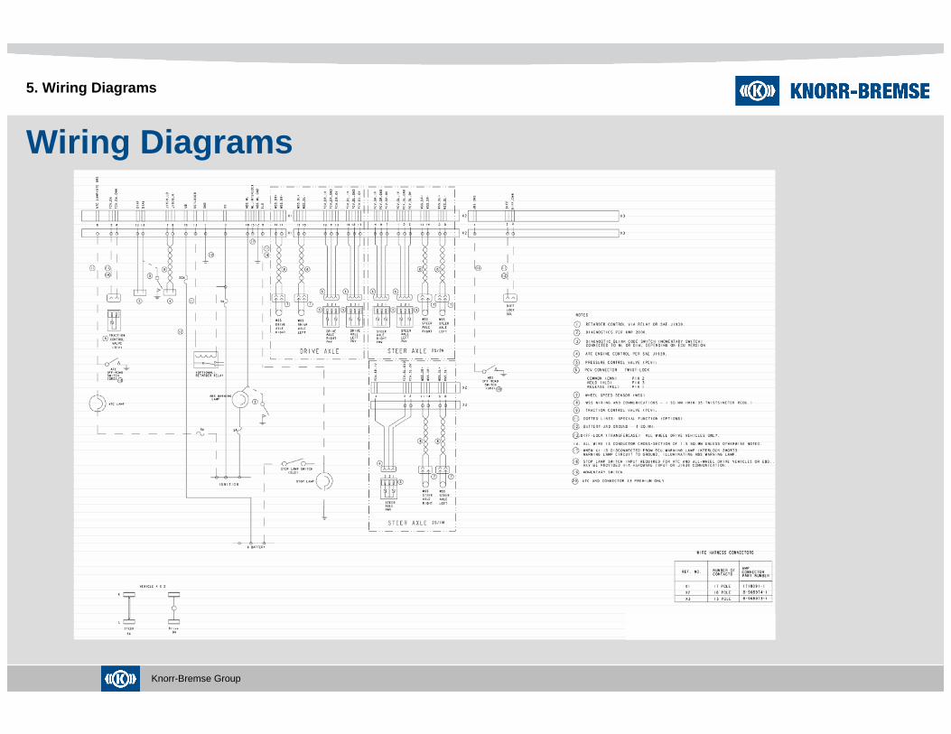
Wiring Diagrams
5. Wiring Diagrams
Knorr-Bremse Group
Wiring Diagrams
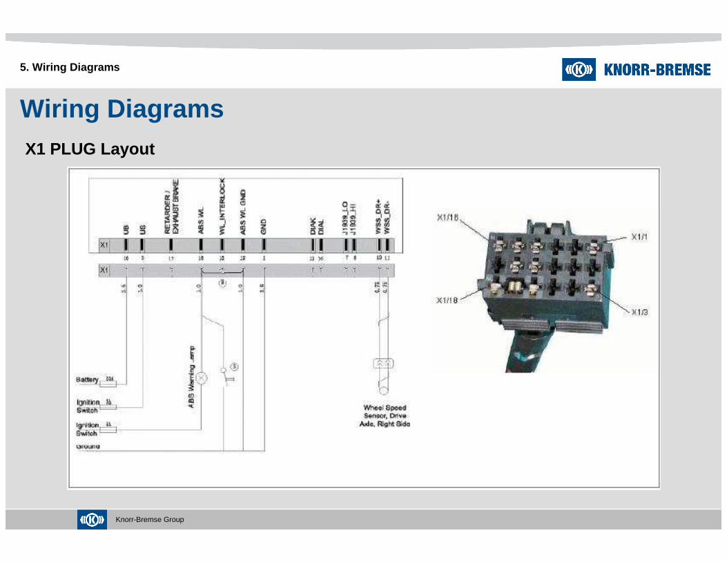
5. Wiring Diagrams
X1 PLUG Layout

Knorr-Bremse Group
Wiring Diagrams
5. Wiring Diagrams
X2 PLUG Layout

Knorr-Bremse Group 64
Thank you for your attention.
Contact
KNORR-BREMSE Korea Ltd.Truck Brake Division6th Floor, Bongwoo B/D, 31-7, 1-Ga, Jangchung-Dong,Jung-Gu, Seoul, 100-391, KoreaPhone: +82 2 2273 1182~3 Fax: +82 2 2273 1184mailto: [email protected]://www.knorr-bremse.com


![Media kit 2010[1].pdf low res..pdf-1](https://static.fdocuments.in/doc/165x107/58f19a9f1a28aba8488b45d9/media-kit-20101pdf-low-respdf-1.jpg)