Trellis and Trestles – Innovative Busway Bridge...
19
Trellis and Trestles – Innovative Busway Bridge Design Dr. S (Bala) Balakrishnan, Ph.D., P.Eng. Associated Engineering, Edmonton Paper prepared for presentation at the Bridges – Links to a Sustainable Future (B) Session of the 2008 Annual Conference of the Transportation Association of Canada Toronto, Ontario
Transcript of Trellis and Trestles – Innovative Busway Bridge...

Trellis and Trestles – Innovative Busway Bridge Design
Dr. S (Bala) Balakrishnan, Ph.D., P.Eng. Associated Engineering, Edmonton
Paper prepared for presentation
at the Bridges – Links to a Sustainable Future (B) Session
of the 2008 Annual Conference of the Transportation Association of Canada
Toronto, Ontario

Trellis and Trestles – Innovative Busway Bridge Design
Page 2 of 19
ABSTRACT An innovative design and construction of a bridge in Edmonton to carry bus traffic from a Light Rail Transit Station is described. The overpass crosses a high volume road at a very high skew and traverses a highly sensitive ground slope. The 455 m long bridge consists of 70 m long “Trellis” structure over the roadway and two “Trestles” type structures, 63 m and 322 m long. The “Trellis” structure consists of twelve 30 m long simple spam precast prestressed concrete NU girders at approximately 6 m spacing, placed perpendicular to the roadway below, over which are placed partial depth precast concrete panels and cast-in-place concrete deck slab. This arrangement avoided the traffic disruption on the roadway and is more economical than a conventional bridge. The “Trestles” consists of 1.5 m diameter cast-in-place concrete piles at 7 m spacing along the length of the bridge, extended up to carry a cast-in-place concrete deck slab, 7.7 m wide and 0.4 m average thickness. The cast-in-place concrete piles act as “shear keys” to provide stability to the soil slopes. The entire structure is designed and constructed as a contractor proposed value engineering alternative to the original tendered design consisting of a conventional two span bridge over the roadway and tangent pile retaining walls at the ground slope, resulting in over $ 0.5 M savings to the Owner.
1. INTRODUCTION
The Belgravia Busway Project is a part of the Light Rail Transit Project in Edmonton, which has been revived in recent years due to increased awareness of the need for sustainability in civil infrastructure. The Belgravia busway is designed for the busses leaving the Neil Crawford Centre Station, currently close to completion, west to merge with Fox Drive, over the Belgraviia Road (see Figure 1). The flyover intersection with Belgravia Road is highly skewed (skew angle of about 70 degrees) and the busway traverses a hill which is potentially unstable. A design involving a two span bridge over Belgravia Road and retaining walls on the cut in the slope was tendered and contract awarded to Albercp Construction of Edmonton. Associated Engineering/Alberco team submitted a value engineering alternative, involving reduction in cost, less traffic disruption, less disturbance of the slope and other advantages. The City of Edmonton has accepted the alternative proposal and is under construction. This paper describes the value engineered busway design and some aspects of construction.
2. COMPARISON OF TENDERED DESIGN AND THE VALUE ENGINEERING DESIGN
2.1 Belgravia Road Flyover (see Figures 1 through 5)
The crossing is highly skewed (about 70 degrees skew). The original tendered design involved a four span bridge (25m – 25m – 50m – 50m spans) with a pier in the median of Belgravia Road. This required widening of the Belgravia Road and traffic accommodation.

Trellis and Trestles – Innovative Busway Bridge Design
Page 3 of 19
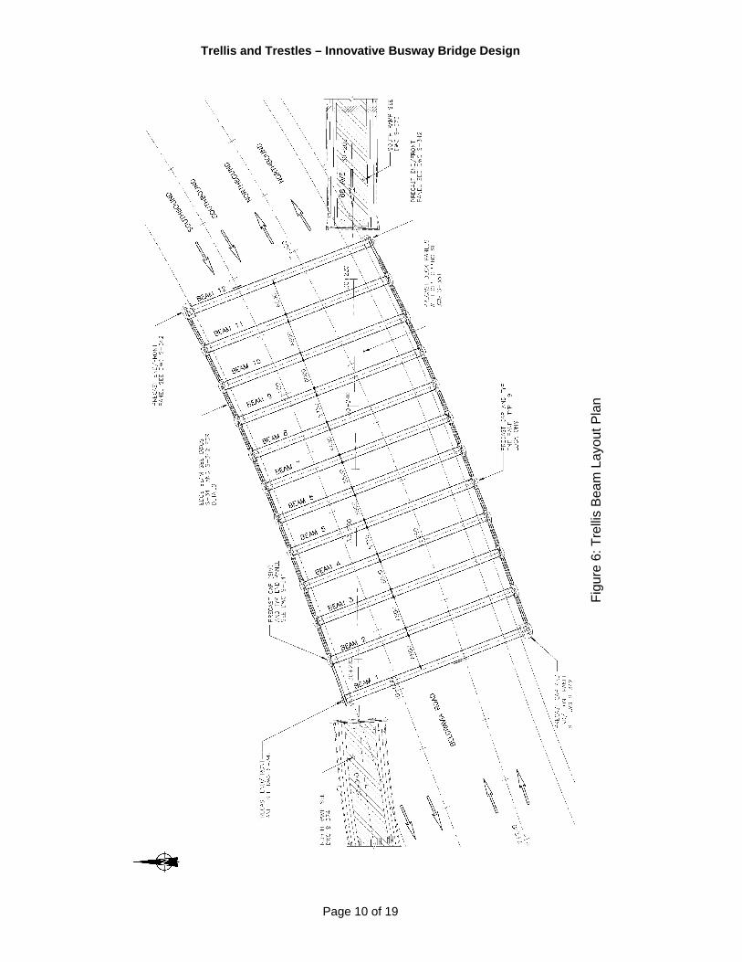
At the east abutment, a Mechanically Stabilized Earth Wall about 240m long was to be built, with height varying from 2m to 4.25m. The depth of superstructure was 2.4m. The value engineering design use the “Trellis Beam” concept developed by the author and was used at the Calgary Trail/Anthony Henday Drive interchange in Edmonton (see “Trellis Beam Bridges – Innovative Solutions for Highly Skewed Flyovers, 2005 TAC Conference Proceedings). The “Trellis Beam Concept” is the structural arrangement wherein the main girders are perpendicular to the underpassing roadway, thus resulting in the least span and shallowest superstructure depth (see Figure 4: Bridge Plan). The flyover structure consists of twelve precast concrete girders spanning 30m, with spacing varying from 5.5m to 6.5m (see Figure 6: Trellis Beam Layout Plan). The girders are 1.35m deep and total superstructure depth is 1.8m. Each girder is supported by a 1.2m diameter column at each end, which in turn is supported by a 0.9m shaft diameter cast-in-place concrete drilled belled pile. The girders are inclined to closely follow the superelevation of the deck surface (see Figure 7: Beam Section). The deck slab consists of 150mm thick precast-prestressed stay-in-place panels with 225mm cast-in-place reinforced concrete topping. This arrangement eliminated the need for pier in the median of the Belgravia Road and the precast panels eliminated the need for any formwork over the road. The need for road widening has also been eliminated. The MSE wall on the east side was eliminated by providing a ‘Trestle’ structure.
2.2 Trestle Structure The tendered design required cutting into the slope for about 200m on the north side (see Figure 2A: Retaining Walls – Tendered Design) and filling on the southside for about 80m (see Figure 2B: Retaining Walls – Tendered Design). Tangent pile wall (with piles varying in diameter from 900mm to 1500mm) is to be used to retain the soil on the northside and cast-in-place concrete wall supported on pile foundation was to be used on the southside. The value engineering design involved the horizontal alignment to be closer to the toe of the slope (towards Belgravia Road) and lowering the vertical profile taking advantage of the reduced superstructure depth at the flyover Trellis structure. The entire ramp is supported on a Trestle type structure, consisting of 1.5m diameter columns spaced at 7m, supporting a cast-in-place reinforced slab, trapezoidal in cross-section (see Figure 9: Cross-Section of Trestle) . A report by AMEC Earth and Environmental Ltd. of Edmonton noted that the project area was originally underlain by a system of creeks that flowed to the northwest towards the river. The thalawegs of these old creeks correspond roughly to the existing alignments of Belgravia Road and Fox Drive. A number of slope instabilities were identified on the north and south slopes of Belgravia Road. Generalized stratigraphy comprised of top soil and fill layers at surface followed by glacio locustrine clays, on top of out-wash sand and silt deposits (see Figure 10: Bridge Profile). The tangent pile walls required pile installation techniques that minimize ground disturbance, such as bored piles using vibro casing or continuous Flight-Augur (CFA). The piles are also required to act as “shear keys” to provide additional resistance against bedrock controlled failure mechanism through a weak bentonite layer at shallow depth.

Trellis and Trestles – Innovative Busway Bridge Design
Page 4 of 19
In the value engineering design the use of 1.5m diameter piles at relatively close spacing of 7m, provides resistance against the slope failure, to a level at least equal to the tangent pile wall. Each column is an extension of the 1.5m diameter cast-in-place concrete pile.
Summary of Slope Stability Analysis
Station Estimated Factor of Safety (ignoring the piles)
Required Horizontal Force to Provide a Minimum Factor of Safety of 1.5
(kN/m of slope)
30+350 1.16 20
30+400 1.14 50
30+440 1.12 40
The ramp slab consists of four segments A,B,C and D. Ramp A on the east side of Belgravia is 63m long, Ramp B is 133m long, Ramp C is 105m long and Ramp D is 82.5m long for a total length of 458m including the Trellis structure. The Trellis structure and the ramp structure segments are allowed to displace independently using expansion joints. The length of the ramp structure segments have been chosen such that the stresses due to volume change movements are minimized. The deck slab is monolithic with the columns, which deflect to accommodate the slab length changes. Ramp B consists of columns with the greatest unsupported length from the ground level, therefore this ramp segment is the longest, at 133m. Soil-structure interaction analyses were performed, taking into account the lateral stiffness of the soil (i.e., modules of subgrade reaction in the horizontal direction), and for cracked and uncracked stiffness of the columns. The 1m wide swale on each side of the deck allows for drainage of the busway without requiring the cross flow where the superelevation changes direction. These swales discharge into catch basins at the west end of the ramp, which are connected to the city sewer system. The top layer of reinforcement in the deck slab is epoxy coated, the High Performance Concrete with Silica Fume (45 MPa strength) and polymer modified asphalt wearing surface provide waterproofing and wear resistance to improve the durability of the bridge. Acknowledgements Alberco Construction is the contractor, whose willingness and enthusiasm in working through this value engineering alternative was instrumental in making this design a reality.

Trellis and Trestles – Innovative Busway Bridge Design
Page 5 of 19
Figu
re 1
: Pla
n –
Tend
ered
Des
ign
Tend
ered
Des
ign
Val
ue E
ngin
eerin
g D
esig
n A
lignm
ent

Trellis and Trestles – Innovative Busway Bridge Design
Page 6 of 19
Figu
re 2
B:
Ret
aini
ng W
alls
– T
ende
red
Des
ign
Figu
re 2
A:
Ret
aini
ng W
alls
– T
ende
red
Des
ign

Trellis and Trestles – Innovative Busway Bridge Design
Page 7 of 19
Figu
re 3
: Val
ue E
ngin
eerin
g D
esig
n

Trellis and Trestles – Innovative Busway Bridge Design
Page 8 of 19
Figu
re 4
: Brid
ge P
lan

Trellis and Trestles – Innovative Busway Bridge Design
Page 9 of 19
Figu
re 5
: Brid
ge E
leva
tion
Trellis and Trestles – Innovative Busway Bridge Design
Page 10 of 19
Figu
re 6
: Tre
llis
Bea
m L
ayou
t Pla
n

Trellis and Trestles – Innovative Busway Bridge Design
Page 11 of 19
Figu
re 7
: Bea
m S
ectio
n
Figu
re 8
: Cro
ss-S
ectio
n of
the
Trel
lis B
ridge
Dec
k

Trellis and Trestles – Innovative Busway Bridge Design
Page 12 of 19
Figure 9: Cross-Section of Trestle

Trellis and Trestles – Innovative Busway Bridge Design
Page 13 of 19
Figu
re 1
0: B
ridge
Pro
file
and
Soi
l Log
s

Trellis and Trestles – Innovative Busway Bridge Design
Page 14 of 19
Figure 11: 3D View of Trellis Structure

Trellis and Trestles – Innovative Busway Bridge Design
Page 15 of 19
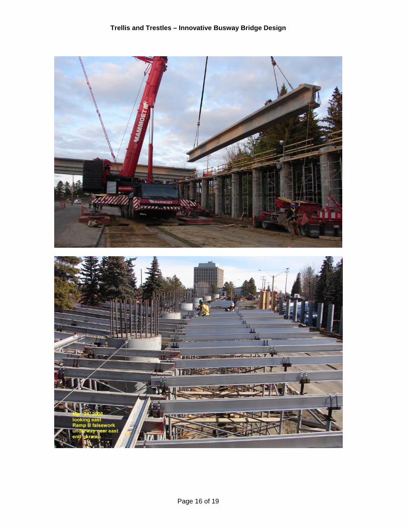
Construction Photos
Trellis and Trestles – Innovative Busway Bridge Design
Page 16 of 19

Trellis and Trestles – Innovative Busway Bridge Design
Page 17 of 19

Trellis and Trestles – Innovative Busway Bridge Design
Page 18 of 19

Trellis and Trestles – Innovative Busway Bridge Design
Page 19 of 19