Transforming Energy Making Use of Pyroelectric: A ...jocet.org/papers/200-E0008.pdf · are...
4
Abstract—A lot of energy around us gets wasted, keeping in mind, the increasing energy demand and scarcity of resources, we have devised an idea to conserve the heat energy, which gets emitted out by the refrigerator. The technique works as follows : a pyrolectric transducer is attached to the compressor pump of the refrigerator, aligned in such a way that one side of it is line other contact with the compressor and other with the wall( ceiling ) or the other part is at room temperature. This temperature of the compressor is approx. 50-75 celsius higher than the room temperature. This creates a temperature difference between the two sided of the transducer which in turn modifies the orientation of the atoms, leading to the change in polarization and thus giving rise to a constant voltage across the transducer(pyroelectric).This transducer is further connected to a capacitor. Due to this voltage across the transducer, the capacitor gets charged up and this can be further used as a supply to any appliance (operating at low voltage). Index Terms—Capacitor, compressor, pyroelectric, sustainable energy. I. INTRODUCTION The heat energy is emitted by the compressor of the refrigerator which leads to an increase in its temperature (dT). dt. Here, denotes the change in the temperature. The compressor is further attached to the pyroelectric substance [1]. A pyroelectric substance when experience a temperature change that generates voltage across it [2]. This temperature change is sensed by the pyro electric, thus generating a voltage across it. The Voltage is generated only if dT/dt>0 or dT/dt<0 (dT/dt represents the change in temperature with respect to time), and no voltage is observed when dT/dt=0. In order to utilize this voltage across the pyroelectric substance [1], the setup is further connected in the capacitor. Since, the connection is in parallel, the same voltage drop occurs across the capacitor [3]. Now, this charged capacitor can be used for small voltage rating appliances. II. COMPRESSOR The refrigerator compressor is both a motor and a pump that move the refrigerant through the system. Temperature sensors signal the compressor to start when the temperature inside the refrigerator rises above its set point [4]. No Manuscript received September 25, 2013; revised April 27, 2014. Shivam Dewan is with the Northern India Engineering College, Guru Gobind Singh Indraprastha University, Delhi, India (e-mail: [email protected]). Paras Arya was with Guru Gobind Singh Indraprastha University, Delhi India (e-mail: [email protected]). refrigerator is completely airtight; cold air leaks out, and warmer air leaks in, causing the temperature to rise above its set point. As the compressor starts, it draws in the cold refrigerant gas in liquid form as it leaves the evaporator [5]. Refrigerators use a type of refrigerant gas that turns into a liquid at very cold temperatures. The compressor then puts pressure on the gas---compressing it. As the gas is compressed, its temperature goes up. The compressor pushes out the hot, compressed gas through the outside metal coils (tubes) on the back or bottom of the refrigerator. These coils allow the heat to dissipate into the surrounding air. Because it is under pressure, the gas changes into a liquid as it cools. The liquid gas continues to flow through the system until it reaches the expansion valve. The valve forces the liquid through a very small hole, turning it into a very cold mist, which evaporates as it moves through the freezer coils. As the cold liquid gas moves through the coils, it draws heat out of the surrounding air in the freezer and refrigerator compartments. This is based on the second law of thermodynamics: heat moves from warmer objects to colder objects. The colder object is the evaporating gas, and the warmer object is the air. The coils lead back to the compressor [4]. When the liquid reaches the compressor, pressure is applied. The compressor sends the hot gas back through the outside coils to release heat into the air. The process of compression and evaporation continues until the refrigerator temperature has returned to its set point. Once the temperature is at its set point, the temperature sensors signal the compressor to stop. As per the observations the temperature of the compressor reaches to a value approximately 50-75*C higher than the room temperature [6]. The compressor works on the second law of the thermodynamics. After the set point is reached, the compressor stops working. Fig. 1. Working of compressor. Transforming Energy Making Use of Pyroelectric: A Conservation Technique Shivam Dewan and Paras Arya Journal of Clean Energy Technologies, Vol. 3, No. 3, May 2015 232 DOI: 10.7763/JOCET.2015.V3.200
Transcript of Transforming Energy Making Use of Pyroelectric: A ...jocet.org/papers/200-E0008.pdf · are...
Abstract—A lot of energy around us gets wasted, keeping in
mind, the increasing energy demand and scarcity of resources,
we have devised an idea to conserve the heat energy, which
gets emitted out by the refrigerator. The technique works as
follows : a pyrolectric transducer is attached to the compressor
pump of the refrigerator, aligned in such a way that one side of
it is line other contact with the compressor and other with the
wall( ceiling ) or the other part is at room temperature. This
temperature of the compressor is approx. 50-75 celsius higher
than the room temperature. This creates a temperature
difference between the two sided of the transducer which in
turn modifies the orientation of the atoms, leading to the
change in polarization and thus giving rise to a constant
voltage across the transducer(pyroelectric).This transducer is
further connected to a capacitor. Due to this voltage across the
transducer, the capacitor gets charged up and this can be
further used as a supply to any appliance (operating at low
voltage).
Index Terms—Capacitor, compressor, pyroelectric,
sustainable energy.
I. INTRODUCTION
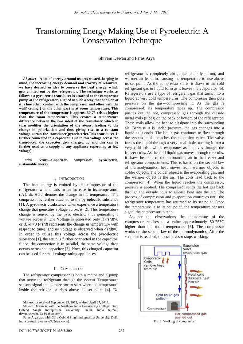
The heat energy is emitted by the compressor of the
refrigerator which leads to an increase in its temperature
(dT). dt. Here, denotes the change in the temperature. The
compressor is further attached to the pyroelectric substance
[1]. A pyroelectric substance when experience a temperature
change that generates voltage across it [2]. This temperature
change is sensed by the pyro electric, thus generating a
voltage across it. The Voltage is generated only if dT/dt>0
or dT/dt<0 (dT/dt represents the change in temperature with
respect to time), and no voltage is observed when dT/dt=0.
In order to utilize this voltage across the pyroelectric
substance [1], the setup is further connected in the capacitor.
Since, the connection is in parallel, the same voltage drop
occurs across the capacitor [3]. Now, this charged capacitor
can be used for small voltage rating appliances.
II. COMPRESSOR
The refrigerator compressor is both a motor and a pump
that move the refrigerant through the system. Temperature
sensors signal the compressor to start when the temperature
inside the refrigerator rises above its set point [4]. No
Manuscript received September 25, 2013; revised April 27, 2014.
Shivam Dewan is with the Northern India Engineering College, Guru
Gobind Singh Indraprastha University, Delhi, India (e-mail: [email protected]).
Paras Arya was with Guru Gobind Singh Indraprastha University, Delhi
India (e-mail: [email protected]).
refrigerator is completely airtight; cold air leaks out, and
warmer air leaks in, causing the temperature to rise above
its set point. As the compressor starts, it draws in the cold
refrigerant gas in liquid form as it leaves the evaporator [5].
Refrigerators use a type of refrigerant gas that turns into a
liquid at very cold temperatures. The compressor then puts
pressure on the gas---compressing it. As the gas is
compressed, its temperature goes up. The compressor
pushes out the hot, compressed gas through the outside
metal coils (tubes) on the back or bottom of the refrigerator.
These coils allow the heat to dissipate into the surrounding
air. Because it is under pressure, the gas changes into a
liquid as it cools. The liquid gas continues to flow through
the system until it reaches the expansion valve. The valve
forces the liquid through a very small hole, turning it into a
very cold mist, which evaporates as it moves through the
freezer coils. As the cold liquid gas moves through the coils,
it draws heat out of the surrounding air in the freezer and
refrigerator compartments. This is based on the second law
of thermodynamics: heat moves from warmer objects to
colder objects. The colder object is the evaporating gas, and
the warmer object is the air. The coils lead back to the
compressor [4]. When the liquid reaches the compressor,
pressure is applied. The compressor sends the hot gas back
through the outside coils to release heat into the air. The
process of compression and evaporation continues until the
refrigerator temperature has returned to its set point. Once
the temperature is at its set point, the temperature sensors
signal the compressor to stop.
As per the observations the temperature of the
compressor reaches to a value approximately 50-75*C
higher than the room temperature [6]. The compressor
works on the second law of the thermodynamics. After the
set point is reached, the compressor stops working.
Fig. 1. Working of compressor.
Transforming Energy Making Use of Pyroelectric: A
Conservation Technique
Shivam Dewan and Paras Arya
Journal of Clean Energy Technologies, Vol. 3, No. 3, May 2015
232DOI: 10.7763/JOCET.2015.V3.200
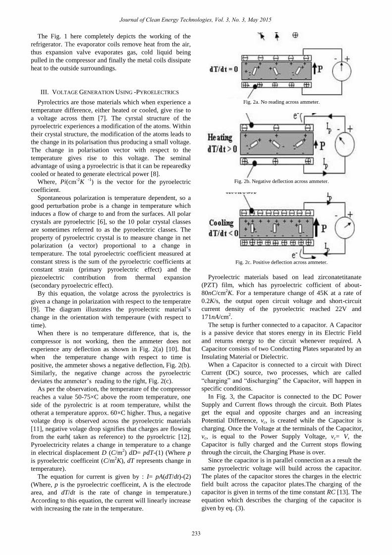
The Fig. 1 here completely depicts the working of the
refrigerator. The evaporator coils remove heat from the air,
thus expansion valve evaporates gas, cold liquid being
pulled in the compressor and finally the metal coils dissipate
heat to the outside surroundings.
III. VOLTAGE GENERATION USING -PYROELECTRICS
Pyrolectrics are those materials which when experience a
temperature difference, either heated or cooled, give rise to
a voltage across them [7]. The cyrstal structure of the
pyroelectric experiences a modification of the atoms. Within
their crystal structure, the modification of the atoms leads to
the change in its polarisation thus producing a small voltage.
The change in polarisation vector with respect to the
temperature gives rise to this voltage. The seminal
advantage of using a pyroelectric is that it can be repearedky
cooled or heated to generate electrical power [8].
Where, Pi(cm-2
K -1
) is the vector for the pyroelectric
coefficient.
Spontaneous polarization is temperature dependent, so a
good perturbation probe is a change in temperature which
induces a flow of charge to and from the surfaces. All polar
crystals are pyroelectric [6], so the 10 polar crystal classes
are sometimes referred to as the pyroelectric classes. The
property of pyroelectric crystal is to measure change in net
polarization (a vector) proportional to a change in
temperature. The total pyroelectric coefficient measured at
constant stress is the sum of the pyroelectric coefficients at
constant strain (primary pyroelectric effect) and the
piezoelectric contribution from thermal expansion
(secondary pyroelectric effect).
By this equation, the volatge across the pyrolectrics is
given a change in polarization with respect to the temperatre
[9]. The diagram illustrates the pyroelectric material’s
change in the orientation with temperaure (with respect to
time).
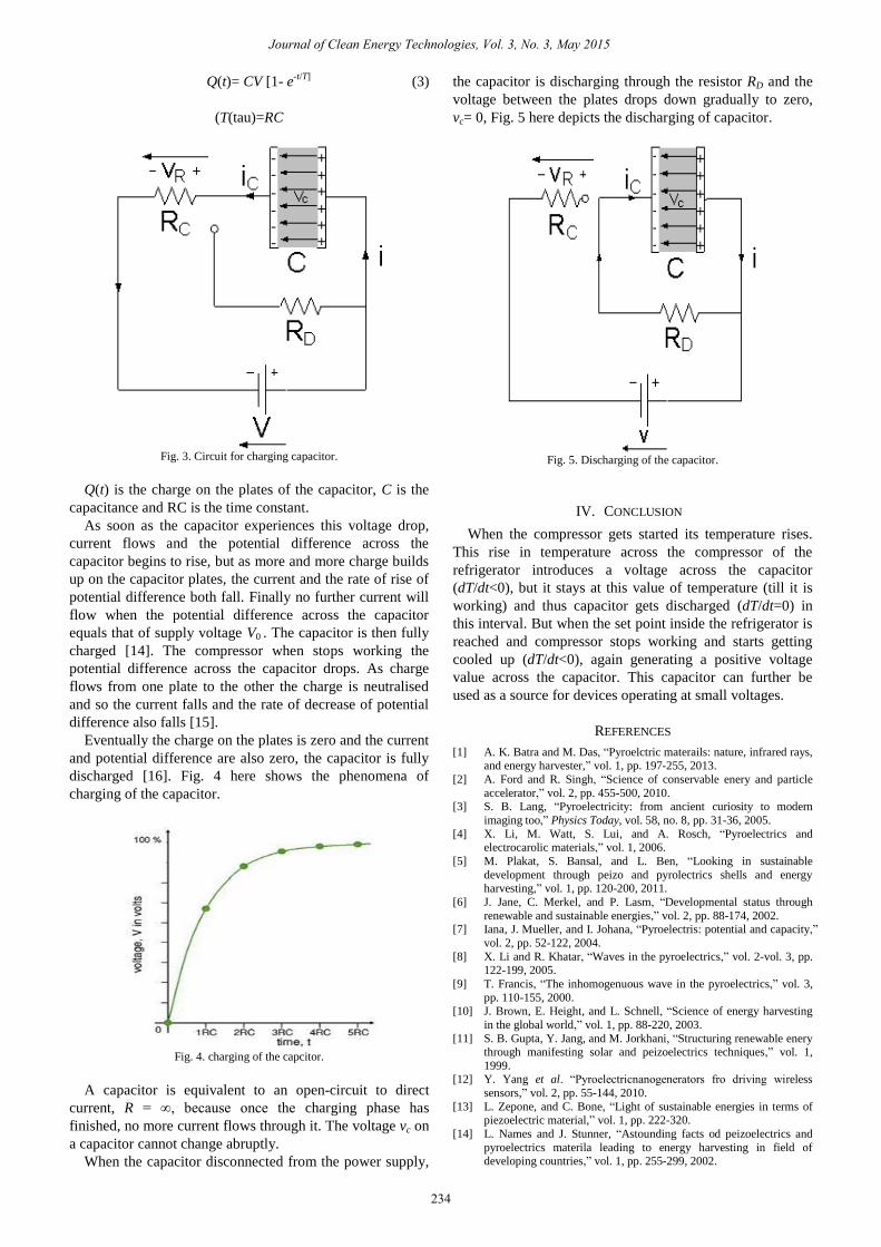
When there is no temperature difference, that is, the
compressor is not working, then the ammeter does not
experience any deflection as shown in Fig. 2(a) [10]. But
when the temperature change with respect to time is
positive, the ammeter shows a negative deflection, Fig. 2(b).
Similarly, the negative change across the pyroelectric
deviates the ammeter’s reading to the right, Fig. 2(c).
As per the observation, the temperature of the compressor
reaches a value 50-75×C above the room temperature, one
side of the pyrolectric is at room temperature, whilst the
otherat a temperature approx. 60×C higher. Thus, a negative
volatge drop is observed across the pyroelectric materials
[11], negative volage drop signifies that charges are flowing
from the earh( taken as reference) to the pyroelctric [12].
Pyroelectricity relates a change in temperature to a change
in electrical displacement D (C/m2) dD= pdT-(1) (Where p
is pyroelectric coefficeint (C/m2K), dT represents change in
temperature).
The equation for current is given by : I= pA(dT/dt)-(2)
(Where, p is the pyroelectric coefficeint, A is the electrode
area, and dT/dt is the rate of change in temperature.)
According to this equation, the current will linearly increase
with increasing the rate in the temperature.
Fig. 2a. No reading across ammeter.
Fig. 2b. Negative deflection across ammeter.
Fig. 2c. Positive deflection across ammeter.
Pyroelectric materials based on lead zirconatetitanate
(PZT) film, which has pyroelectric cofficient of about-
80nC/cm2K. For a temperature change of 45K at a rate of
0.2K/s, the output open circuit voltage and short-circuit
current density of the pyroelectric reached 22V and
171nA/cm2.
The setup is further connected to a capacitor. A Capacitor
is a passive device that stores energy in its Electric Field
and returns energy to the circuit whenever required. A
Capacitor consists of two Conducting Plates separated by an
Insulating Material or Dielectric.
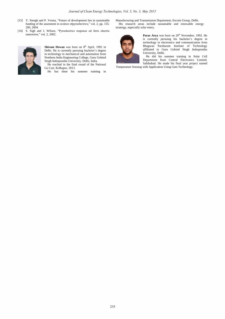
When a Capacitor is connected to a circuit with Direct
Current (DC) source, two processes, which are called
“charging” and “discharging” the Capacitor, will happen in
specific conditions.
In Fig. 3, the Capacitor is connected to the DC Power
Supply and Current flows through the circuit. Both Plates
get the equal and opposite charges and an increasing
Potential Difference, vc, is created while the Capacitor is
charging. Once the Voltage at the terminals of the Capacitor,
vc, is equal to the Power Supply Voltage, vc= V, the
Capacitor is fully charged and the Current stops flowing
through the circuit, the Charging Phase is over.
Since the capacitor is in parallel connection as a result the
same pyroelectric voltage will build across the capacitor.
The plates of the capacitor stores the charges in the electric
field built across the capacitor plates.The charging of the
capacitor is given in terms of the time constant RC [13]. The
equation which describes the charging of the capacitor is
given by eq. (3).
Journal of Clean Energy Technologies, Vol. 3, No. 3, May 2015
233
Q(t)= CV [1- e-t/T]
(3)
(T(tau)=RC
Fig. 3. Circuit for charging capacitor.
Q(t) is the charge on the plates of the capacitor, C is the
capacitance and RC is the time constant.
As soon as the capacitor experiences this voltage drop,
current flows and the potential difference across the
capacitor begins to rise, but as more and more charge builds
up on the capacitor plates, the current and the rate of rise of
potential difference both fall. Finally no further current will
flow when the potential difference across the capacitor
equals that of supply voltage V0 . The capacitor is then fully
charged [14]. The compressor when stops working the
potential difference across the capacitor drops. As charge
flows from one plate to the other the charge is neutralised
and so the current falls and the rate of decrease of potential
difference also falls [15].
Fig. 4. charging of the capcitor.
Fig. 5. Discharging of the capacitor.
IV. CONCLUSION
When the compressor gets started its temperature rises.
This rise in temperature across the compressor of the
refrigerator introduces a voltage across the capacitor
(dT/dt<0), but it stays at this value of temperature (till it is
working) and thus capacitor gets discharged (dT/dt=0) in
this interval. But when the set point inside the refrigerator is
reached and compressor stops working and starts getting
cooled up (dT/dt<0), again generating a positive voltage
value across the capacitor. This capacitor can further be
used as a source for devices operating at small voltages.
REFERENCES
[1] A. K. Batra and M. Das, “Pyroelctric materails: nature, infrared rays, and energy harvester,” vol. 1, pp. 197-255, 2013.
[2] A. Ford and R. Singh, “Science of conservable enery and particle
accelerator,” vol. 2, pp. 455-500, 2010. [3] S. B. Lang, “Pyroelectricity: from ancient curiosity to modern
imaging too,” Physics Today, vol. 58, no. 8, pp. 31-36, 2005.
[4] X. Li, M. Watt, S. Lui, and A. Rosch, “Pyroelectrics and electrocarolic materials,” vol. 1, 2006.
[5] M. Plakat, S. Bansal, and L. Ben, “Looking in sustainable
development through peizo and pyrolectrics shells and energy harvesting,” vol. 1, pp. 120-200, 2011.
[6] J. Jane, C. Merkel, and P. Lasm, “Developmental status through
renewable and sustainable energies,” vol. 2, pp. 88-174, 2002. [7] Iana, J. Mueller, and I. Johana, “Pyroelectris: potential and capacity,”
vol. 2, pp. 52-122, 2004.
[8] X. Li and R. Khatar, “Waves in the pyroelectrics,” vol. 2-vol. 3, pp. 122-199, 2005.
[9] T. Francis, “The inhomogenuous wave in the pyroelectrics,” vol. 3,
pp. 110-155, 2000. [10] J. Brown, E. Height, and L. Schnell, “Science of energy harvesting
in the global world,” vol. 1, pp. 88-220, 2003.
[11] S. B. Gupta, Y. Jang, and M. Jorkhani, “Structuring renewable enery through manifesting solar and peizoelectrics techniques,” vol. 1,
1999. [12] Y. Yang et al. “Pyroelectricnanogenerators fro driving wireless
sensors,” vol. 2, pp. 55-144, 2010.
[13] L. Zepone, and C. Bone, “Light of sustainable energies in terms of piezoelectric material,” vol. 1, pp. 222-320.
[14] L. Names and J. Stunner, “Astounding facts od peizoelectrics and
pyroelectrics materila leading to energy harvesting in field of developing countries,” vol. 1, pp. 255-299, 2002.
Journal of Clean Energy Technologies, Vol. 3, No. 3, May 2015
234
Eventually the charge on the plates is zero and the current
and potential difference are also zero, the capacitor is fully
discharged [16]. Fig. 4 here shows the phenomena of
charging of the capacitor.
A capacitor is equivalent to an open-circuit to direct
current, R = ∞, because once the charging phase has
finished, no more current flows through it. The voltage vc on
a capacitor cannot change abruptly.
When the capacitor disconnected from the power supply,
the capacitor is discharging through the resistor RD and the
voltage between the plates drops down gradually to zero,
vc= 0, Fig. 5 here depicts the discharging of capacitor.
[15] Y. Siengh and P. Verma, “Future of development lies in sustainable
funding of the assesment in sceince ofpyroelectrics,” vol. 2, pp. 155-
200, 2004. [16] S. Sigh and J. Wilson, “Pyroelectrics response od ferro electric
nanowires,” vol. 2, 2002.
Shivam Dewan was born on 8th April, 1992 in
Delhi. He is currently persuing bachelor’s degree in technology in mechanical and automation from
Northern India Engineering College, Guru Gobind
Singh Indraprastha University, Delhi, India. He reached in the final round of the National
Go Cart, Kolhapur, 2013.
He has done his summer training in
Manufacturing and Transmission Department, Escorts Group, Delhi.
His research areas include sustainable and renewable energy
stratergy, especially solar enery.
Journal of Clean Energy Technologies, Vol. 3, No. 3, May 2015
235
Paras Arya was born on 20th November, 1992. He
is currently persuing his bachelor’s degree in technology in electronics and communication from
Bhagwan Parshuram Institute of Technology
affiliated to Guru Gobind Singh Indraprastha University, Delhi.
He did his summer training in Solar Cell
Department from Central Electronics Limited,Sahibabad. He made his final year project named
Temperature Sensing with Application Using Gsm Technology.


![FT-infrared and pyroelectric studies on calix[8]arene ...shura.shu.ac.uk/20141/1/10697448.pdf · FT-infrared and pyroelectric studies on calix[8]arene Langmuir-Blodgett films Pyroelectric](https://static.fdocuments.in/doc/165x107/5ed0d44f92578a06cf4a87dd/ft-infrared-and-pyroelectric-studies-on-calix8arene-shurashuacuk201411.jpg)
![OPTICAL PROPERTIES · Piezoelectric 2(s E or E s) d α 10 – 103 pm/V [3 pm/V in quartz] actuators, sensors, transducers, motors, MEMS, energy harvesters Pyroelectric (DT 3E) p α](https://static.fdocuments.in/doc/165x107/607ab373621b70758013cea0/optical-properties-piezoelectric-2s-e-or-e-s-d-10-a-103-pmv-3-pmv-in-quartz.jpg)