
Transformer's Book a Travel Over Different Aspects of Transformers, Inductors and Transductors -...
304
-
Upload
hisonecks72 -
Category
Documents
-
view
282 -
download
11
Transcript of Transformer's Book a Travel Over Different Aspects of Transformers, Inductors and Transductors -...

7/25/2019 Transformer's Book a Travel Over Different Aspects of Transformers, Inductors and Transductors - Humberto de So…
http://slidepdf.com/reader/full/transformers-book-a-travel-over-different-aspects-of-transformers-inductors 1/304

7/25/2019 Transformer's Book a Travel Over Different Aspects of Transformers, Inductors and Transductors - Humberto de So…
http://slidepdf.com/reader/full/transformers-book-a-travel-over-different-aspects-of-transformers-inductors 2/304
Transformers, Inductors and transductors Design with different aspects like ski
depth, eddy currents, proximity, strange, final and gap effects. Optimization of size an
discussion of special featured transformers, like Kfactor transformers design.
Rio de Janeiro
Transformer’s Book
A travel over different aspects of transformers,
inductors and transductors
Humberto de Souza
First Edition
2015

7/25/2019 Transformer's Book a Travel Over Different Aspects of Transformers, Inductors and Transductors - Humberto de So…
http://slidepdf.com/reader/full/transformers-book-a-travel-over-different-aspects-of-transformers-inductors 3/304
50729S Souza, Humberto de, 1948
Transformer’s Book - A travel over different aspects of transformers,
inductors and transductors / Humberto de Souza. – Rio de Janeiro:
2015
306 P.: 25.4 Cm
ISBN 978-85-920396-0-8
1.Transformers 2.Additional Losses and Design
1 Title
CCD: 600
CDU: 537.37
First Edition

7/25/2019 Transformer's Book a Travel Over Different Aspects of Transformers, Inductors and Transductors - Humberto de So…
http://slidepdf.com/reader/full/transformers-book-a-travel-over-different-aspects-of-transformers-inductors 4/304
Humberto de Souza - 2015 - All Rights Reserved. No part of this publication may be
reproduced or stored in any form or by any means without the prior permission of the
Author.

7/25/2019 Transformer's Book a Travel Over Different Aspects of Transformers, Inductors and Transductors - Humberto de So…
http://slidepdf.com/reader/full/transformers-book-a-travel-over-different-aspects-of-transformers-inductors 5/304
To my Father and Mother

7/25/2019 Transformer's Book a Travel Over Different Aspects of Transformers, Inductors and Transductors - Humberto de So…
http://slidepdf.com/reader/full/transformers-book-a-travel-over-different-aspects-of-transformers-inductors 6/304
Index:
A Brief History
What Is a Transformer?
The physics behind the scenes
Structure of the Matter and a brief view over atomic physics
Magnetism and Magnetic Materials
Magnetism
Ferromagnetic Materials
The ferromagnetic domains
Ferromagnetic Domains and domain walls
Initial Concepts
Ampere´s Law
Magnetization
Flux Density B:
Matlab Model:
Permeability
Measurement of permeability:
Amplitude permeability
Initial Permeability, Rayleigh Constant and Rayleigh law.
Absolute and relative permeability
Complex permeability
Apparent permeability
Differential permeability
Magnetostriction
Inductance and Inductors
What is Inductance?

7/25/2019 Transformer's Book a Travel Over Different Aspects of Transformers, Inductors and Transductors - Humberto de So…
http://slidepdf.com/reader/full/transformers-book-a-travel-over-different-aspects-of-transformers-inductors 7/304
Reluctance
Losses in Magnetics Materials
Losses
The measurement of losses:
Representation of losses
General Losses
Hysteresis losses:
Classical losses:
Excess Losses
Facts affecting the total losses
Loss behavior in different magnetic materials.
Soft ferrites for high frequency applications:
Searching for a general loss model which could include harmonics and DC
currents:
The MSE Approach - (Modified Steinmetz Equation)
The GSE Approach (General Steinmetz Equation)
Combination of fields
Ampere´s Law in depth.
For the Sake of simplicity
Magnetic field produced by currents in endless sheets
Addition of fields in two parallel plates
Infinite Solenoid
Addition of fields in several layers:
Two overlapping solenoids
Simulation by FEA (Finite Element Analysis)
Equivalent Circuit of a transformer:
Leakage Inductance
7/25/2019 Transformer's Book a Travel Over Different Aspects of Transformers, Inductors and Transductors - Humberto de So…
http://slidepdf.com/reader/full/transformers-book-a-travel-over-different-aspects-of-transformers-inductors 8/304
What is leakage Inductance
The definition of a fundamental inductance equation departing from the
energy stored in magnetic field:
Inductance formula definition (Toroidal Case):
Inductance Formula definition (Leakage inductance Case):
The equivalent circuit of a transformer and measurements of AC Resistance:
The equivalent circuit:
AC resistance Measurement
Measurement of DC resistance
High frequencies response:
Medium frequencies Response
Low frequencies response
Skin Depth and Proximity Effect
Skin Depth
Ampere Law in more Detail:
Diffusion of magnetic field in a Conductor
Simple Rules in order to handle fields and currents in a single face.
Direction of the current
Simple Rules
Diffusion interrupted by change of field or current direction
Proximity Effect:
The proximity effect develops considerable losses.
Proximity Effect three-dimensional configurations.
Simplifying assumptions
Consequences:
Transformation from a round conductor winding to metal plate or sheet
Dowell transformed circular wire windings into an “Equivalent Sheet” as

7/25/2019 Transformer's Book a Travel Over Different Aspects of Transformers, Inductors and Transductors - Humberto de So…
http://slidepdf.com/reader/full/transformers-book-a-travel-over-different-aspects-of-transformers-inductors 9/304
follows.
Eddy Currents
Forming a unique sheet:
Square of the current
Second Layer
Determination of Fr for the entire coil:
Sample Calculation of AC resistance for primary and secondary windings
due to skin and proximity effect
Dowell Relations – Simplifying the figure:
Expanding in series for simplification:
Applicability
Skin and Proximity effects facing complex waveforms
Behavior for complex waveforms
We need to treat the problem through losses:
Determination of the Kr Curve.
Using Kr for loss calculation.
Further simplification with harmonics
First Example: Calculation of a 4 Layers transformer with Copper sheet in
the two coils.
Second example: Calculating ht losses:
Another method for the calculation of Fr
Solution other than for paper and pencil:
Calculation in the design of a 20Kva inverter filter inductor
Design of a ferrite 3Kva 200Khz power transformer for a ZVS-QRC
telecommunication SMPS.
The Gap Losses - The approach
The visual effect of the gaps

7/25/2019 Transformer's Book a Travel Over Different Aspects of Transformers, Inductors and Transductors - Humberto de So…
http://slidepdf.com/reader/full/transformers-book-a-travel-over-different-aspects-of-transformers-inductors 10/304
Determination of losses by finite elements:
The calculation of losses in Litz Wires
The End Effect
The problem of the size
The definition of the equation that determines the flux density B, departing from
frequency, voltage and magnetic cross sectional area of the core:
EI Core transformer:
Calculating over a single Phase EI lamination transformer
Design of a sample E I transformer:
Determination of the better cost for a three phase transformer
K Factor and K Factor transformers
The problem of the loads and the current spectrum
The K Factor definition:
Different topologies of non linear loads and the K Factor:
A simplified but full precision, Matlab-Simulink K Factor Calculator.
The IEC 62040 standard for UPS systems and the non linear input interface
power supply for personal computers.
The effect on the neutral current
Classification of K factor according to loads and lines.
Formulas group:
Sample project of a 50Kva three Phase distribution transformer for Kfactor = 13
Solutions for skin depth
Conductor plate or foil
Interleaving winding
Winding Construction for Minimum Losses:
Planar Windings
REFERENCES

7/25/2019 Transformer's Book a Travel Over Different Aspects of Transformers, Inductors and Transductors - Humberto de So…
http://slidepdf.com/reader/full/transformers-book-a-travel-over-different-aspects-of-transformers-inductors 11/304
Index of all volumes

7/25/2019 Transformer's Book a Travel Over Different Aspects of Transformers, Inductors and Transductors - Humberto de So…
http://slidepdf.com/reader/full/transformers-book-a-travel-over-different-aspects-of-transformers-inductors 12/304
Transformer’s Book
Introduction

7/25/2019 Transformer's Book a Travel Over Different Aspects of Transformers, Inductors and Transductors - Humberto de So…
http://slidepdf.com/reader/full/transformers-book-a-travel-over-different-aspects-of-transformers-inductors 13/304
A Brief History
The transformer was primarily invented in 1831 by Michael Faraday and since
then, scattered over the history in many industrial and residential applications.
Its great impulse took place after the win of Nicholas Tesla over Thomas AlvaEdison in the “War of Currents” where both, defended opposed positions about AC or DC
distribution of electrical Energy.
In that occasion, the selection of the Alternating Current demonstrated being more
attractive then Direct Current distribution, due to its natural properties of manageability
and easily conversion of voltage levels.
Exactly in the center of this discussion, was the transformer, the main responsiblefor the conversion of the levels of voltages in the electrical distribution systems.

7/25/2019 Transformer's Book a Travel Over Different Aspects of Transformers, Inductors and Transductors - Humberto de So…
http://slidepdf.com/reader/full/transformers-book-a-travel-over-different-aspects-of-transformers-inductors 14/304
What Is a Transformer?
A transformer is basically composed by two coils of metallic wires, insulated
superficially by varnish, allowing being mounted together in a same iron core.
The existence of the Iron core, allows to couple magnetically the two coils in abetter way, and due to its magnetic properties, reducing the currents developed in the coils.
This particular is going to be seen later on.
When exists an AC voltage applied in the input coil called “Primary” will appear
in the other coil, called “Secondary” a voltage that is proportional to the relation of turns
between the two coils.
That property of transformation of the voltage from one level of voltage to anotheror several others is the main feature of it. The level of voltage is changed but the power is
invariable, meaning that isn´t changed the energy level

7/25/2019 Transformer's Book a Travel Over Different Aspects of Transformers, Inductors and Transductors - Humberto de So…
http://slidepdf.com/reader/full/transformers-book-a-travel-over-different-aspects-of-transformers-inductors 15/304
The physics behind the scenes
We must understand that the main objective of this brief discussion is to give an
aerial view about the mechanisms of the magnetism in magnetic materials. In addition a
remembering of the magnetic terms and the definition of certain values involved in them.
We depart from the principle that everyone that opens this book understands
entirely such subject.
This book is far from being a beginners book. It is intended to be a book for
experienced engineers or technicians, that already design transformers and is concerned in
advanced topics of optimization.
It’s a book of few words . The subjects are treated in mathematics and visual basisin order to transmit concepts mainly through the experience of visual effects.
The mathematical is intentionally kept in a low level with the main aim to be
understood by most of the people.
The book was designed in tree independent volumes that obeys a logical and a
structural knowledge sequence oriented for better understanding.

7/25/2019 Transformer's Book a Travel Over Different Aspects of Transformers, Inductors and Transductors - Humberto de So…
http://slidepdf.com/reader/full/transformers-book-a-travel-over-different-aspects-of-transformers-inductors 16/304
Structure of the Matter and a brief view over atomic physics
Democritus, a philosopher of antiquity, proposed that the matter is formed of tiny
invisible particles called “Atoms” that means “indivisible”. This idea was followed by His
group called Atomists and during a lot of time; this theory was maintained as the main
explanation of the matter.
For Democritus the huge variety of materials in nature came from the movements
of the different types of the atoms
Others contributed with this theory, like Epicurus proposed a limit for the size of
the atoms explaining its invisibility.
Aristotle changed the path, proposing that everything is composed bycombinations of 4 elements, Fire, Air, Earth and Water.
John Dalton, in 1803, trying to explain the behavior of the various atmospheric
gases and gas mixtures, resumed the atomic hypothesis. Just as Leucippus, Democritus
and Epicurus, Dalton they believed that matter was composed of indivisible atoms and
empty space. They imagined the atom as a small sphere with mass defined and
characteristic properties. Thus, all chemical transformations could be explained by the
arrangement of atoms. All matter is composed of atoms. These are the smallest particles
that constitute it, are indivisible and indestructible, and cannot be transformed into other,
even during chemical phenomena. The atoms of the same chemical element are identical
in mass and behave equally in chemical transformations. Chemical transformations occur
by separation and union of atoms. That is, atoms of a substance that are combined in a
certain way, separate, joining together again in a different way.
The British Joseph John Thomson discovered the electron in 1897 through
experiments involving cathode ray tubes. The cathode ray tube is in a vial containing only
vacuum and an electrical device that makes the electrons jump from any conductive
material and form bundles, which are themselves cathode. Thomson, studying cathode
rays, discovered that these are affected by electric and magnetic fields and deduced that
the deflection of cathode rays by these fields are deviations from trend of very small
particles of negatively charged electrons.
Thomson proposed that the atom was therefore divisible, in positively and
negatively charged particles, contrary to the indivisible atom model proposed by Dalton
(and atomistic in Ancient Greece). The atom consists of several electrons embedded and

7/25/2019 Transformer's Book a Travel Over Different Aspects of Transformers, Inductors and Transductors - Humberto de So…
http://slidepdf.com/reader/full/transformers-book-a-travel-over-different-aspects-of-transformers-inductors 17/304
incorporating in a large particle positive, like raisins in a pudding. The atomic model of
the “pudding with raisins” remained in vogue until the discovery of the atomic nucleus by
Ernest Rutherford.
In 1911, experimenting bombing sheets of gold with alpha particles (positively
charged particles, released by radioactive elements), Rutherford made an important
observation: the vast majority of particles passed through directly to the blade, and some
others suffered minor deviations in very small number (one hundred thousand), suffered
large deviations in the opposite direction.
From these observations, Rutherford came to the following conclusions:
In the atom there are empty spaces; most of the particles passed through the bypass
without conceding any effect…
In the center of the atom has a nucleus very small and dense, some alpha particles
collide with this core and returned without crossing the blade.
The nucleus has a positive charge; alpha particles passing near him were repelled
and therefore suffered deviation in its trajectory.
By Rutherford atomic model, the atom consists of a central core, provided with
positive electric charges (protons) surrounded by a cloud of negative charges (electrons).
Rutherford has also shown that virtually all mass is concentrated in the small atom
core region.
Two years after Rutherford have created your model; the Danish scientist Niels
Bohr completed it, creating what is now called planetary model. For Bohr, the electrons
revolve in circular orbits around the nucleus. After these new studies were made and new
atomic models were created. The model represents the atom as having a central part called
core, containing protons and neutrons, serves to explain a large number of comments on
materials.
Niels Bohr in the beginning of the XX century described the atom, departing from
Quantum electromagnetic radiations, proposed by Albert Einstein and Max Plank,
depicted more completely an atom as a planetary system like the model of Rutherford,
where negative charges turns around positive and neutral charges. In reality the electrons
are clouds of probability surrounding the nucleus.
There are many problems with this model, like there is with any model that is
proposed, because the behavior of those mechanisms, are not completely understood,

7/25/2019 Transformer's Book a Travel Over Different Aspects of Transformers, Inductors and Transductors - Humberto de So…
http://slidepdf.com/reader/full/transformers-book-a-travel-over-different-aspects-of-transformers-inductors 18/304
being all, mere parables about reality.
There are many constituents of universe and matter, space, time, particles and
forces. The main forces of our interest are gravity and electromagnetic forces, being the
last one, derived from the photons interactions.
Today there are so many theories about the fundamental structure of our universeand matter, but many of all are no totally understood, like string theory, super string
theory, M theory and other that depicts partially the behavior of particles movements, time
and forces. All in elegant theories and even opening ways for a most ambitious and vast
theory of everything, where the relativity theory and Quantum mechanics could be
unified, being the dream and the Holy Grail of the modern physicists.
But still today where such theories didn´t gain their structure to evolves the
explanation of our physical and engineering models, explaining our daily life. The Bohr
atomic model is still in the practice to explain them.

7/25/2019 Transformer's Book a Travel Over Different Aspects of Transformers, Inductors and Transductors - Humberto de So…
http://slidepdf.com/reader/full/transformers-book-a-travel-over-different-aspects-of-transformers-inductors 19/304
Magnetism and Magnetic Materials

7/25/2019 Transformer's Book a Travel Over Different Aspects of Transformers, Inductors and Transductors - Humberto de So…
http://slidepdf.com/reader/full/transformers-book-a-travel-over-different-aspects-of-transformers-inductors 20/304
Magnetism
To understand the cause of magnetism we must begin with the atoms, from which
the materials are built, and consider first of all the structure of the individual atom. At the
center there is the nucleus around which electrons orbit in a complicated manner.
We need concern ourselves here only with the electrons; we can ignore the nucleus
because of its small magnetic contribution.
Each single electron possesses in the first place an electric charge; more important
for us, however, is the fact that it also has its own magnetic (spin) moment. The single
electron already behaves like a tiny bar magnet, and the ferromagnetism that we are trying
to explain is ultimately only the effect, summed under prescribed conditions in a specific
way, of a huge number of such electron magnets. Besides the spin each electron of the
atom possesses a further magnetic moment (Orbital moment) caused by its rotation around
the nucleus. A movement of charge of this kind produces a magnetic effect exactly as does
an ordinary circulating current.
In a larger atom numerous electrons with spins and orbital moments, are present; in
an iron atom, for example, there are 26 electrons arranged in shells. The abundance of
magnetic moments in the individual atoms seems at first impossible to estimate.Fortunately, however there are very strict laws in the atom governing the magnitude and
direction of the individual contributions. Their effect is for contributions either wholly or
partially to cancel out, so that frequently there is no resultant magnetic moment in the
single atom or in some cases only that of one or a few electrons.
For a single in isolation there is thus a definite magnetic moment which we may
ascribe to a conceptual atomic magnet (Elementary magnet).
In a metal we are not therefore dealing with individual atoms existing completely
independently of one another; on the contrary there is an interaction between the atoms
which is of vital importance to the metal performance. We must therefore turn first to the
structure of metals.
Metals are normally crystalline solid bodies consisting of a large number of grains
(Crystallites) tightly united by grain boundaries (Fig 1.1)
Magnetism in Materials

7/25/2019 Transformer's Book a Travel Over Different Aspects of Transformers, Inductors and Transductors - Humberto de So…
http://slidepdf.com/reader/full/transformers-book-a-travel-over-different-aspects-of-transformers-inductors 21/304
In nature, magnetism is presented by some substances .Depending their individual
natures; they present different amount and properties like ferromagnetism,
ferrimagnetisms, anti-ferromagnetism paramagnetism and diamagnetism.
Ferromagnetism is a physical phenomenon where there is an existence of a
magnetic ordainment of all the magnetic momentum of material that externally presents an
observable force of attraction and retention by a magnet. At same form in the
ferrimagnetism, is observed an ordainment of the magnetic momentum, but in this case,
some of them in the opposite direction, but they are randomly distributed and is not
enough to cancel the attraction effect.
In the Anti-ferromagnetism, is observed the same ordainment of all magnetic
Momentum, but in both direction in a so ordered way, that cancels any observable
attraction
Paramagnetism is the trend of all free individual momentum of the material to
align parallel with an applied field. When do not exist any applied field it does not present
any magnetic property.
The great majority the substances are diamagnetic. This property was first
observed by Sebald Justinus Brugmans in 1778 and first nominated by Michael Faraday
in September of 1945, when he had seen a piece of bismuth be repulsed by a magnetizedbar. An interesting experience is a piece of a diamagnetic material being levitated by a
magnetic bar. The experience of a superconductor being levitated by a magnetic field is
due to this diamagnetic property.
At present we are interested only with the strongest of those five “magnetisms”
Called ferromagnetism.

7/25/2019 Transformer's Book a Travel Over Different Aspects of Transformers, Inductors and Transductors - Humberto de So…
http://slidepdf.com/reader/full/transformers-book-a-travel-over-different-aspects-of-transformers-inductors 22/304
Ferromagnetic Materials
An iron atom presents numerous electrons, with spins and orbital moments.
In this example 26 electrons are arranged in shells. The contribution of the
magnetic moments of individual atoms seems to be impossible to predict. Fortunately
there are ways to describe the magnetism phenomena. We need to descent to the interior of
the matter and begin with the atoms, from which the matter is built. In its simplified model
in the center of the atoms are the protons and neutrons that form the nucleus around witch
the electrons revolves in a complicated manner.
Our worry need be only with the electrons, because the amount of magnetism
presented by the nucleus is negligible
An Electron presents an electrical charge and has its own magnetic (spin) moment.
The single electron already behaves like tiny magnetic bar. The ferromagnetism we are
beginning to explain is ultimately only the effect, summed under prescribed conditions in
a specific way, of a huge number of such electron magnets. Besides the spin effect, each
electron of the atom possesses an additional magnetic moment (Orbital Moment) caused
by its rotation around the nucleus. A movement of charge of this kind produces a magnetic
effect, exactly as done by awes of physics governing the magnitude and direction of the
individual contributions.
For a single isolated atom there is a magnetic moment which we may relate to a
conceptual atomic magnet. In a metal we are not therefore dealing with individual atoms.
There are groups of atoms related. They are intrinsically coupled by their individual
magnetic forces this groups we call “Domains”.

7/25/2019 Transformer's Book a Travel Over Different Aspects of Transformers, Inductors and Transductors - Humberto de So…
http://slidepdf.com/reader/full/transformers-book-a-travel-over-different-aspects-of-transformers-inductors 23/304
The ferromagnetic domains
In magnetic materials, there are groups of atoms linked together through their
forces. We call them domains. Such domains works like them were a single magnet. The
coupling forces between those domains are of big importance in such phenomena. In
ferromagnetic materials they are of so technical importance, that at room temperature theyare so aligned, that are all entirely paralleled working all like they were one only magnet.
If the temperature rises, atomic agitation contributes to misalignment of such domains.
Reaching such point where this alignment is lost. This temperature is called the Curie
temperature, being approximately 770 ºC for iron and 360 ºC for nickel
Metals are normally Crystalline solid bodies consisting of a large number of grains
(Crystallites) tightly united by grain boundaries. In all crystallites the atoms are arrangedregularly in a space structure; in individual crystallites however, the structure is generally
oriented in different ways. There are quite a number of such structures; for example, at
room temperature nickel has a cubic-face-centered structure, iron a cubic-space-centered
structure (figs 1 and 2).
Fig. 1 – Space structure of the nickel

7/25/2019 Transformer's Book a Travel Over Different Aspects of Transformers, Inductors and Transductors - Humberto de So…
http://slidepdf.com/reader/full/transformers-book-a-travel-over-different-aspects-of-transformers-inductors 24/304
Fig. 2 Space structure of the iron
In a metal crystal of this type the electrons of the atoms are more weakly bound to
the atomic nuclei than in a single free atom.
The outermost electrons specially make them independent and move around
almost freely in the metal crystal. This leads to the high electrical conductivity of metals.
The electrons are then, however, in a state of mutual interaction and as a result
their magnetic moments arrange themselves ant parallel almost exception. The free
electrons are thus able to contribute virtually nothing to the magnetism of the metal, but
the situation is different with the other electrons that have remained in the vicinity of their
atomic nucleus. They do in fact to large extent cancel one another out of their magnetic
effect. I a number of cases, however, as with the individual atoms, some magnetic
moments remain uncompensated at each lattice site in the metal crystal there reposes, in a
manner of speaking , a small magnet. These magnets are in fact prerequisite of
ferromagnetism. If these tiny magnets were not intercooled in some way, they would
possess all possible directions, as long as no external magnetic field is present. Just as the
lattice atoms themselves execute thermal vibrations caused by temperature, the atomic
magnets are continually changing their directions.
In most cases, however the atomic magnets in the solid are intercoupled. If the
effect of coupling forces is to make the atomic magnets arrange themselves parallel at the
lattice sites, we are concerned with ferromagnetism. The moments of the individual atoms
then add up. These conditions apply, for example, for iron, nickel, and cobalt.
The coupling forces between atomic magnets at lattice sites thus decide the
occurrence of ferromagnetism.

7/25/2019 Transformer's Book a Travel Over Different Aspects of Transformers, Inductors and Transductors - Humberto de So…
http://slidepdf.com/reader/full/transformers-book-a-travel-over-different-aspects-of-transformers-inductors 25/304
Ferromagnetic Domains and domain walls
In the ferromagnetic materials of technical importance the coupling forces inside
are generally so powerful that atomic magnetic magnets at room temperature are almost
entirely parallel-aligned. If, however, we raise the temperature, then thermal directional
oscillations of the atomic magnets increase steadily and finally become so strong that thecoupling forces are overcome. This occurs with various ferromagnetic metals and alloys at
Cleary defined temperatures, known as the Curie temperatures. For iron, the Curie
temperatures is 770 ºC; for nickel, 360 ºC.
Fig. 3 Randomly arranged domains
Thus, it is only below the Curie temperature that the atomic magnets in a
ferromagnetic material are aligned in parallel by the coupling forces.
The boundaries between the domains are called domain walls or Bloch walls
(After F. Bloch). Such a wall is not only a boundary; it is more a transition layer with its
own system of laws. Its thickness may range from several hundred of thousand atomic
distances.
Fig. 4 Aligned arranged domains
Within the wall the orientation of the atomic magnets changes in screw like
fashion from the direction of the one domain into that of the other, as fig. 5 shows
diagrammatically. In so doing, torsions arise opposing the forces acting (for example the
coupling and anisotropy forces); the wall has thereby certain energy content

7/25/2019 Transformer's Book a Travel Over Different Aspects of Transformers, Inductors and Transductors - Humberto de So…
http://slidepdf.com/reader/full/transformers-book-a-travel-over-different-aspects-of-transformers-inductors 26/304
Fig. 5 – Domain and domain Wall

7/25/2019 Transformer's Book a Travel Over Different Aspects of Transformers, Inductors and Transductors - Humberto de So…
http://slidepdf.com/reader/full/transformers-book-a-travel-over-different-aspects-of-transformers-inductors 27/304
Initial Concepts

7/25/2019 Transformer's Book a Travel Over Different Aspects of Transformers, Inductors and Transductors - Humberto de So…
http://slidepdf.com/reader/full/transformers-book-a-travel-over-different-aspects-of-transformers-inductors 28/304
Ampere´s Law
Fig. 6 A current produces a surrounding magnetic field
Fig. 7 – One turns crossing the center of the toroid
Fig. 8 – The magnetic path length in a toroidal core

7/25/2019 Transformer's Book a Travel Over Different Aspects of Transformers, Inductors and Transductors - Humberto de So…
http://slidepdf.com/reader/full/transformers-book-a-travel-over-different-aspects-of-transformers-inductors 29/304
Fig. 8A The Cross Sectional area Aeff in green
The cross sectional area is that one perpendicular with the lines of magnetic force.
The numer of line crossing it constitutes the flux and the number of lines per unit square is
the flux density like gauss and Tesla units.
Fig. 9 - Two turns passing through the center of the toroid
The concept of one turn is like show in fig 7 and Fig. 9, where the turn is passing
through the center of a Toroid. In this sense can be said in fig. 9 that there is one turn of 2
ampere or 2 turns of 1 ampere each.

7/25/2019 Transformer's Book a Travel Over Different Aspects of Transformers, Inductors and Transductors - Humberto de So…
http://slidepdf.com/reader/full/transformers-book-a-travel-over-different-aspects-of-transformers-inductors 30/304

7/25/2019 Transformer's Book a Travel Over Different Aspects of Transformers, Inductors and Transductors - Humberto de So…
http://slidepdf.com/reader/full/transformers-book-a-travel-over-different-aspects-of-transformers-inductors 31/304
Flux Density B:
We saw determining the flux density over the field H. The final imposition of flux
density is dependent on the material characteristics such as permeability, but there is a way
to directly impose flux density. Let consider de faraday´s law in its differential notation:
Solving:
Making:
Solving both sides:
Rearranging:
We can see in a rather simplified form that, with the arrangement of the coil and
core was produced an integrator. Translating to the Simulink of the MatLab We can shownow the dynamic System:
Fig. 12 The number of turns in a core with a cross sectional area produces an “Integrator”
This is produced by the growing field that induces an equal voltage in the oppositedirection. The field is forced to grow slowly behaving like an integrator. The integrator
constant is dependent solely of the number of turns and the cross sectional area of the

7/25/2019 Transformer's Book a Travel Over Different Aspects of Transformers, Inductors and Transductors - Humberto de So…
http://slidepdf.com/reader/full/transformers-book-a-travel-over-different-aspects-of-transformers-inductors 32/304
core.

7/25/2019 Transformer's Book a Travel Over Different Aspects of Transformers, Inductors and Transductors - Humberto de So…
http://slidepdf.com/reader/full/transformers-book-a-travel-over-different-aspects-of-transformers-inductors 33/304
Matlab Model:
Fig. 13 - Simulink flux density calculator
In this model, we can see that the flux density is not dependent of the iron
characteristics. It can be represented solely by a linear integrator and a constant term.
This can apparently be simple, but it is a very powerful model, since it is modeledin Laplace, where all models can be analyzed algebraically, without any difficulty. Besides
the fact that structured on this basic model, we can build more complex structures.
We have experienced the construction of many complex systems involving
different disciplines, like electrical circuits, thermal behavior and some mechanical
structures like inertial movements of trains and more, all working together and giving
dozens of information at same time, including animation and visualization, like in a simple
videogame.
Let us consider 100 Volts applied to a coil of 100 Turns in a Core with cross
sectional area of 100 Cm2. At the end of 10 milliseconds:
Let us see in the Matlab the behavior with the time:

7/25/2019 Transformer's Book a Travel Over Different Aspects of Transformers, Inductors and Transductors - Humberto de So…
http://slidepdf.com/reader/full/transformers-book-a-travel-over-different-aspects-of-transformers-inductors 34/304
Fig. 14 – Behavior of the flux density in the core (Totally independent of the core material)
From this approach we can see now that the plotting of B-H curve can be done in amore simple way.
In a core at virgin state (Remanence=0), we can apply a constant voltage in the
coil. By other side we can measure the H strength through the current, as shown in fig 15
Fig. 15 – Simulink block diagram to plot the virgin curve of the core
Close the switch during the time required to the flux density reaching the
maximum value of interest. Plot the results in a osciloscope of memory as illustrated in the
fig.16
The voltage is applied to the vertical chanel input that will show the flux density
axis. The Output of the const2 is applied to the Horizontal chanel, that will plot the field
strenght H.

7/25/2019 Transformer's Book a Travel Over Different Aspects of Transformers, Inductors and Transductors - Humberto de So…
http://slidepdf.com/reader/full/transformers-book-a-travel-over-different-aspects-of-transformers-inductors 35/304
In the screen of the scope will be plotted the curve shown in fig.16 that represents
the behaviour of the field strenght H as a function of the flux density stimulation of the
core.
The analog to digital conversion is not represented in our circutry and they are
represented soleily by the current and voltage “Meas” interfaces, stardards of the Matlab
Symulink CAE system.
The addoption of any commercial interface with the real world for data acquisition
is possisble and we have some special tools that can be used.
National Instruments also has a lot of DAQ (Data acquisition systems like
Analog/Digital converters and many other appliances). They also have softwares for use
for the implementation of such measurement systems.
Fig. 16 Virgin B-H curve
Using the same system we can plot the entire hysteresis loop, changing only the
switch and battery by a voltage generator. The constants are same.

7/25/2019 Transformer's Book a Travel Over Different Aspects of Transformers, Inductors and Transductors - Humberto de So…
http://slidepdf.com/reader/full/transformers-book-a-travel-over-different-aspects-of-transformers-inductors 36/304
Fig. 17 - Simulink Block diagram for complete hysteresis loop plotting
Voltage applied
Fig 18
Fig. 18 – Voltage waveform of the oscillator
The Amplitude of voltage and frequency must be calculated for each case.
Flux Density

7/25/2019 Transformer's Book a Travel Over Different Aspects of Transformers, Inductors and Transductors - Humberto de So…
http://slidepdf.com/reader/full/transformers-book-a-travel-over-different-aspects-of-transformers-inductors 37/304
Fig. 19
Plotting using such system in which we connect the Vertical and horizontal
channels of the oscilloscope to B and H signals respectively. In the oscilloscope will be
formed a parametric Lissajous figure, we will observe the hysteresis loop like presented in
fig. 20
Fig. 20
Such figure, we can see the “Virgin curve” formed by the dashed line O-L. In this
condition, the domains of the core will be aligned gradually without any anterior
influences. Can be noted in the reverse path, when the curve L-M passes through the
vertical axis (H=0). The core is not demagnetized, presenting a B, which is calledremanence. This is due to the fact that there is a mutual influence between domains that
keeps them aligned, maintaining the magnetization effect. To demagnetize, rearranging

7/25/2019 Transformer's Book a Travel Over Different Aspects of Transformers, Inductors and Transductors - Humberto de So…
http://slidepdf.com/reader/full/transformers-book-a-travel-over-different-aspects-of-transformers-inductors 38/304
them to a rest state, where there isn’t any mutual influence, we need to apply a reverse
magnetic field called “Coercive force.”

7/25/2019 Transformer's Book a Travel Over Different Aspects of Transformers, Inductors and Transductors - Humberto de So…
http://slidepdf.com/reader/full/transformers-book-a-travel-over-different-aspects-of-transformers-inductors 39/304
Permeability
Magnetic permeability is a physical quantity that defines the ability of a magnetic
material to develop a magnetic flux density B, departing from a magnetic strength field H.
Normally is represented by the Greek letter μ.
The relation between flux density B and the field strength H is:
μ =B/H
The development of the flux density follows the alignment of the domains of the
magnetic material contributing each one with its own magnetic field. Due to this fact is
shown a (Multiplicative effect) of the flux density from the applied field strength.
Additionally, such multiplication factor is not constant, showing that thepermeability presents a strong non linear behavior.
When all the domains were aligned the magnetic material reaches a condition that
we call “Saturation” and the extra amount of flux density would be only that generated by
the extra field strength.
Between the initial and final flux density (Saturation) there is a point where the
permeability presents its maximum value.
There are many different permeability values:

7/25/2019 Transformer's Book a Travel Over Different Aspects of Transformers, Inductors and Transductors - Humberto de So…
http://slidepdf.com/reader/full/transformers-book-a-travel-over-different-aspects-of-transformers-inductors 40/304
Measurement of permeability:
Permeability of the virgin curve (Magnetization Curve):
With the same circuit with few modifications, we can plot the virgin curve directly
in the oscilloscope or in a computer. In the circuit of fig 21, we are using two delayed
steps (Step 1 and Step 2), Delayed one in relation to the other with a time window
required to the measurement.
The comparator at the bottom of the diagram is responsible to open the window in
the time required to the measurement.
Fig. 21 Diagram in Simulink for the plotting the permeability of the “Virgin Curve”

7/25/2019 Transformer's Book a Travel Over Different Aspects of Transformers, Inductors and Transductors - Humberto de So…
http://slidepdf.com/reader/full/transformers-book-a-travel-over-different-aspects-of-transformers-inductors 41/304
Amplitude permeability
The relative permeability periodically alternating, following the flux density and
field strength variation in an alternating fashion, forms a waveform of permeability.
The peak of such permeability waveform is called amplitude permeability.

7/25/2019 Transformer's Book a Travel Over Different Aspects of Transformers, Inductors and Transductors - Humberto de So…
http://slidepdf.com/reader/full/transformers-book-a-travel-over-different-aspects-of-transformers-inductors 42/304
Initial Permeability, Rayleigh Constant and Rayleigh law.
At low alternating periodic fields the magnetism behaves like a quadratic curve as
described by Lord Rayleigh. This quadratic equation is known as Rayleigh law and occurs
at Rayleigh´s region. The field, bellow certain level like shown in Fig. 22 the permeability
is constant and the hysteresis loop obey the Rayleigh Law. The main parameters are the
initial permeability μi and Rayleigh constant n.
The initial permeability is that incremental permeability found at very low ac fieldsof excitation. It is found in the data sheet of magnetic material, with this name: Initial
permeability end have to be used only at very low excitation fields.
Fig. 22 Below certain point the permeability is constant

7/25/2019 Transformer's Book a Travel Over Different Aspects of Transformers, Inductors and Transductors - Humberto de So…
http://slidepdf.com/reader/full/transformers-book-a-travel-over-different-aspects-of-transformers-inductors 43/304
Absolute and relative permeability
This is manly referenced as the permeability of vacuum and can be found in many
constant table of Physics as μo, however the absolute permeability of a certain material is
the total permeability found in it:
Always in this book we will be dealing with relative permeability.

7/25/2019 Transformer's Book a Travel Over Different Aspects of Transformers, Inductors and Transductors - Humberto de So…
http://slidepdf.com/reader/full/transformers-book-a-travel-over-different-aspects-of-transformers-inductors 44/304
Complex permeability
Due to the phase shift between flux density and field strength in the alternating
field their quotient in complex notation is likewise a complex quantity. In such a view the
permeability comprises a real and imaginary part.
The customary notation applicable is in particular for a small excitation and under
sinusoidal magnetization during linear behavior.

7/25/2019 Transformer's Book a Travel Over Different Aspects of Transformers, Inductors and Transductors - Humberto de So…
http://slidepdf.com/reader/full/transformers-book-a-travel-over-different-aspects-of-transformers-inductors 45/304
Apparent permeability
The relation is between the inductance of a coil with core and the inductance of the
same coil without core.
Mapp=L/L’

7/25/2019 Transformer's Book a Travel Over Different Aspects of Transformers, Inductors and Transductors - Humberto de So…
http://slidepdf.com/reader/full/transformers-book-a-travel-over-different-aspects-of-transformers-inductors 46/304
Differential permeability
Is the permeability Mdiff at any point on the hysteresis loop for small values of B
and H, that H, Thai is, db and dh tending to zero and gives the local gradients of the loop.
In the case of materials with a rectangular it is the quoted, for example, for the
point of the coercive field strength end the point of remanence.

7/25/2019 Transformer's Book a Travel Over Different Aspects of Transformers, Inductors and Transductors - Humberto de So…
http://slidepdf.com/reader/full/transformers-book-a-travel-over-different-aspects-of-transformers-inductors 47/304
Magnetostriction
The deformation observed in a body of magnetic material when submitted to a
magnetic field. It is observed a change in length or in volume. Both are important featuresof magnetic materials.
With alternating fields the behavior is rather different due to the fact that the skin
depth of the eddy currents restricts the penetration and the material behaves differently in
each surface layer in the direction towards the interior of the body.
The Magnetostriction is an important feature, mainly as a noise source in
transformers.

7/25/2019 Transformer's Book a Travel Over Different Aspects of Transformers, Inductors and Transductors - Humberto de So…
http://slidepdf.com/reader/full/transformers-book-a-travel-over-different-aspects-of-transformers-inductors 48/304
Inductance and Inductors
7/25/2019 Transformer's Book a Travel Over Different Aspects of Transformers, Inductors and Transductors - Humberto de So…
http://slidepdf.com/reader/full/transformers-book-a-travel-over-different-aspects-of-transformers-inductors 49/304
What is Inductance?
The inductance is the property of one component called inductor that presents a
voltage drop proportional to the variation of current that flow through it.
There are two principles that govern the inductance:
1)A steady current creates a steady magnetic field as governed by Ampere’s Law.
2)A Variation of magnetic field produces a voltage in its terminals as governed by
Faraday’s Law.
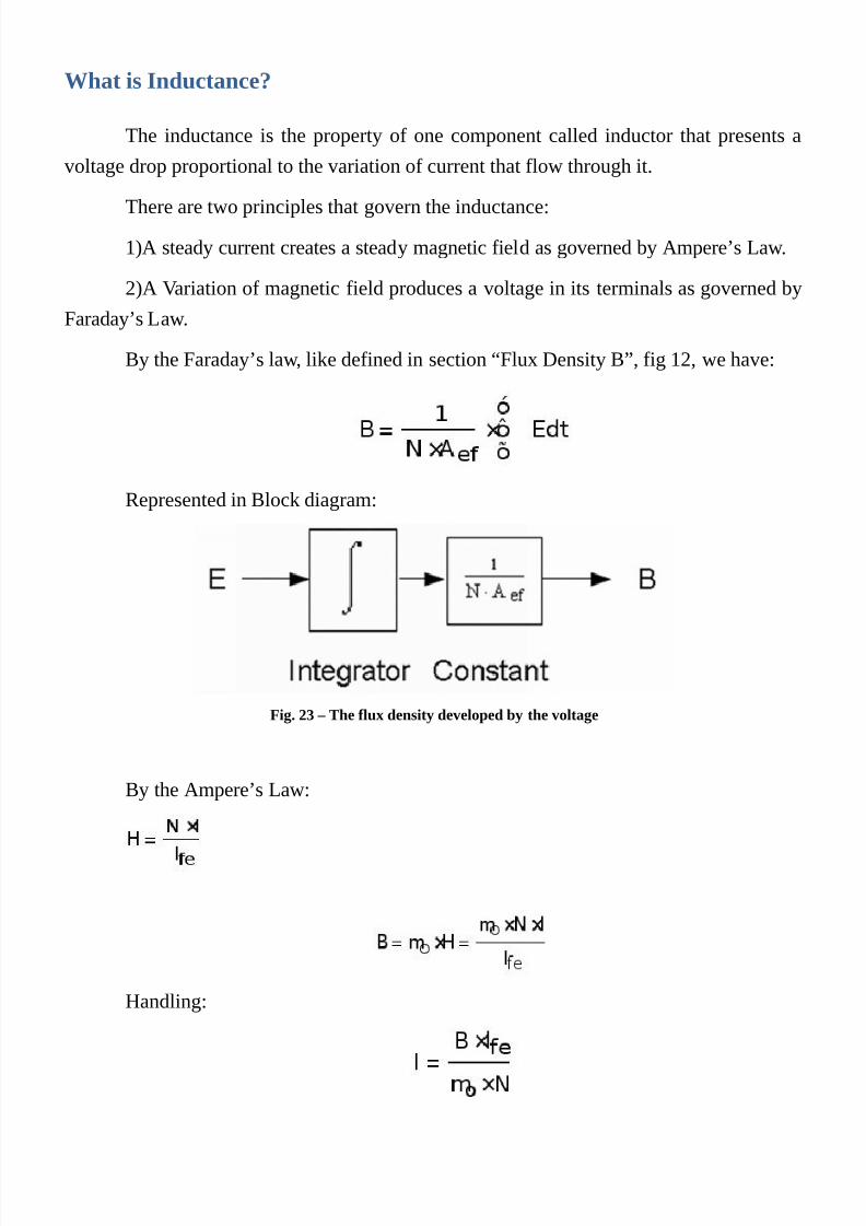
By the Faraday’s law, like defined in section “Flux Density B”, fig 12, we have:
Represented in Block diagram:
Fig. 23 – The flux density developed by the voltage
By the Ampere’s Law:
Handling:

7/25/2019 Transformer's Book a Travel Over Different Aspects of Transformers, Inductors and Transductors - Humberto de So…
http://slidepdf.com/reader/full/transformers-book-a-travel-over-different-aspects-of-transformers-inductors 50/304
Fig. 24 – There isn´t any time delay between flux density and the current
Chaining the two blocks diagrams, we have:
Fig. 25 I(t) as function of e(t)
Simplifying, we get:
Fig. 26 I(t) as a function of E(t) in an inductor
Or in differential form:
Fig. 27 Voltage as a function of the variation of current
In other words:

7/25/2019 Transformer's Book a Travel Over Different Aspects of Transformers, Inductors and Transductors - Humberto de So…
http://slidepdf.com/reader/full/transformers-book-a-travel-over-different-aspects-of-transformers-inductors 51/304
Where:
We have simultaneously defined two things:
The first one is the inductance that is the ability of the inductor to inducing a
voltage due to a variation of the current that flows through it.
The second one is the calculation of an inductor, departing from their dimensions
and Physical parameters.
The term Inductance was named by the English Physicist and mathematician
Olivier Heaviside. The unity for inductance is the Henry with the symbol H in honor of
Joseph Henry.
Is attributed the value of 1 Henry to an inductor that submitted to a current
variation of 1 Amp per second, display a voltage drop of 1 volt. Inversely if an inductor of
1 Henry is submitted to a voltage of 1 volt, it will present a variation of current of 1 amp
per second.
By the same origin, other consequent relations must be defined:
The complete formula for inductance:

7/25/2019 Transformer's Book a Travel Over Different Aspects of Transformers, Inductors and Transductors - Humberto de So…
http://slidepdf.com/reader/full/transformers-book-a-travel-over-different-aspects-of-transformers-inductors 52/304
Including the relative Permeability, we have:

7/25/2019 Transformer's Book a Travel Over Different Aspects of Transformers, Inductors and Transductors - Humberto de So…
http://slidepdf.com/reader/full/transformers-book-a-travel-over-different-aspects-of-transformers-inductors 53/304

7/25/2019 Transformer's Book a Travel Over Different Aspects of Transformers, Inductors and Transductors - Humberto de So…
http://slidepdf.com/reader/full/transformers-book-a-travel-over-different-aspects-of-transformers-inductors 54/304
Reluctance
The reluctance of the magnetic circuit is the ratio of the MMF to the magnetic flux.
It is analogous to a resistance in an electrical circuit.
Thus:

7/25/2019 Transformer's Book a Travel Over Different Aspects of Transformers, Inductors and Transductors - Humberto de So…
http://slidepdf.com/reader/full/transformers-book-a-travel-over-different-aspects-of-transformers-inductors 55/304
The reluctance can be used exactly as resistances in an electric circuit that can be
put in series or parallel or even combination of them in a more complex array.
Let us see some possibilities:
Fig. 28 – Core geometry for the calculation of reluctance
There are 2 parts of an iron core; the length of each piece is 50 cm. Theeffective area is 29 * 35 = 1015Cm2. There is an air gap of 10 cm. The permeability of the
core is 2000. What is the total reluctance?
There is an silicon iron core with lfe=158cm, lg=2cm, Aef=100Cm2

7/25/2019 Transformer's Book a Travel Over Different Aspects of Transformers, Inductors and Transductors - Humberto de So…
http://slidepdf.com/reader/full/transformers-book-a-travel-over-different-aspects-of-transformers-inductors 56/304
Fig. 29 – Core geometry for the calculation of reluctance
Now let us arrange the formula to calculate the inductance.

7/25/2019 Transformer's Book a Travel Over Different Aspects of Transformers, Inductors and Transductors - Humberto de So…
http://slidepdf.com/reader/full/transformers-book-a-travel-over-different-aspects-of-transformers-inductors 57/304
Adjusting the unit for centimeter, we get:
Having 100 turns, we get:
If we neglect the spreading of the flux in the gap, we can consider that we have
reluctance with a resultant permeability:

7/25/2019 Transformer's Book a Travel Over Different Aspects of Transformers, Inductors and Transductors - Humberto de So…
http://slidepdf.com/reader/full/transformers-book-a-travel-over-different-aspects-of-transformers-inductors 58/304
Calculating:
This is the resultant permeability of the total magnetic circuit:
And the total reluctance is:
Calculating the flux density of the Inductor:
Considering the current in the inductor equal to100A, we have:

7/25/2019 Transformer's Book a Travel Over Different Aspects of Transformers, Inductors and Transductors - Humberto de So…
http://slidepdf.com/reader/full/transformers-book-a-travel-over-different-aspects-of-transformers-inductors 59/304

7/25/2019 Transformer's Book a Travel Over Different Aspects of Transformers, Inductors and Transductors - Humberto de So…
http://slidepdf.com/reader/full/transformers-book-a-travel-over-different-aspects-of-transformers-inductors 60/304
Losses in Magnetics Materials

7/25/2019 Transformer's Book a Travel Over Different Aspects of Transformers, Inductors and Transductors - Humberto de So…
http://slidepdf.com/reader/full/transformers-book-a-travel-over-different-aspects-of-transformers-inductors 61/304
Losses
Among the most important features of the cores used in magnetic components are
the losses.
They are responsible for heating and efficiency in most applications. Mostly thelosses are surveyed by their own manufactures that presents their behavior in the
specifications sheets, through graphs or tables as a function of frequency and flux density.
In the last times is customary that they present the losses in the format of a
modified Steinmetz equation for their manufactured materials.

7/25/2019 Transformer's Book a Travel Over Different Aspects of Transformers, Inductors and Transductors - Humberto de So…
http://slidepdf.com/reader/full/transformers-book-a-travel-over-different-aspects-of-transformers-inductors 62/304
The measurement of losses:
The classical method of measurement of losses is through the observation of the
behavior of the current and voltage as response for an excitation applied to a sample.
The application of the excitation can be done through a curled coil in the core
sample with has a convenient shape. There is another coil that is used to read the voltage,
measuring indirectly the flux density by the application of a numerical external constant
over the value measured. This numerical constant depends on the core geometry and the
number of turns of the coil.
A sinusoidal voltage is applied, the voltage and current are measured andcomputed the instantaneous product of both. The average value over each cycle is also
computed and the result is the average loss in watts of that material. Plotting all the values,
changing the frequency and the flux density (By the voltage), the total figure of the
material can be surveyed.
In many cases the measurement can be done through an digital oscilloscope that
can perform the measurements, multiplication and integration, giving at the end, the
average calculation of the product over the entire cycle.
Another solution is the employment of special data acquisition modules like that
one’s of National Instruments, which can acquire data in a fast fashion. All the other
calculation done, inside a computer through, MatLab or even in NI software Labview or
on an specially designed software.
In certain materials like ferrites is important that all the measurements must be
made under rigorous temperature control.
Mostly there are two ways to control the temperature in the samples being tested:
one is the employment of a environmental chamber, but the problem is that a massive
body with a wide external surface, must be attached, to get good coupling between
internal environment temperature controlled and the material under test.
One other method is the “Bath method” that the material is steeped in a bath of
vegetal oil with controlled temperature.
The two methods must take in consideration of the influence of the observer in the
measurement and consequently care must be taken to not influence the measures with the

7/25/2019 Transformer's Book a Travel Over Different Aspects of Transformers, Inductors and Transductors - Humberto de So…
http://slidepdf.com/reader/full/transformers-book-a-travel-over-different-aspects-of-transformers-inductors 63/304
excitations that must be done in a short period of time to no lead power to the DUT
(Device under test). Is interesting to give some calculated interval, between test in
accordance with the total mass and the power delivered in each measurement.

7/25/2019 Transformer's Book a Travel Over Different Aspects of Transformers, Inductors and Transductors - Humberto de So…
http://slidepdf.com/reader/full/transformers-book-a-travel-over-different-aspects-of-transformers-inductors 64/304
Representation of losses
The modeling of losses in the cores is complex and many attempts have been made
toward this, direction in order to we get the means to calculate losses in different
formulations of problems, in the broad spectrum of applications that we try to cover.
The historical model is the famous equation proposed by Steinmetz in 1892,
known as Steinmetz equation.
In which Pi was the average loss per unit volume or Weight, K a constant, B the
flux density, and b a coefficient.
Currently, most manufacturers provide data through a “Modified Steinmetz
equation”, in which has been introduced the dependence of frequency f.
Unfortunately, these data relate only to sinusoidal excitation, and for theapplications of oriented grain silicon steel, used in distribution applications, is useful, but
for others, with rich harmonic waveforms or in cases of ferrite to switching power
supplies or even inductors with rich harmonic currents, it is impossible to use them.

7/25/2019 Transformer's Book a Travel Over Different Aspects of Transformers, Inductors and Transductors - Humberto de So…
http://slidepdf.com/reader/full/transformers-book-a-travel-over-different-aspects-of-transformers-inductors 65/304
General Losses
Due to the complexity of the matter, one looks for the phenomenological laws
summarizing in simple terms the regularities observed in experiments.
The natural path is the separation of the phenomena involved, to study in detail
each one of them.
We can then classify 3 different aspects contributing to the total losses. Ph, Pcl and
Pexc, termed hysteresis loss, classical loss, and excess loss.
Such separation of terms reflects the existence of three scales in the magnetization
process; the scale set by the specimen geometry (Classical loss), the scale of domain wall-
pinning mechanisms (Hysteresis loss) and the scale of magnetic domains.
As can be seen the strongly nonlinear character of the magnetization process, there
is no obvious reason why the superposition law expressed should hold true under broad
conditions.

7/25/2019 Transformer's Book a Travel Over Different Aspects of Transformers, Inductors and Transductors - Humberto de So…
http://slidepdf.com/reader/full/transformers-book-a-travel-over-different-aspects-of-transformers-inductors 66/304
Hysteresis losses:
Hysteresis losses are the consequence of the fact that on microscopic scale the
magnetization process proceeds through sudden jumps of the magnetic domains walls thatare pressed by the external field. The local eddy currents induced by induction, change
accompanying the wall jump, dissipating a finite amount of energy through the Joule
effect. The sum over the jumps gives the hysteresis loss associated with the jump
sequence.
The jumps are so short (Of the order of 10-8 ~10 -9 S) that the external field is
unable to influence the internal jump dynamics.
The only effect of the field is to compress or expand the time interval between
subsequent jumps in inverse proportion to the field rate of change which yield a number of
umps per unit time and an amount of energy dissipated per unit time, proportional to the
magnetization frequency. Therefore for the hysteresis loss in a loop of peak induction B,
one obtains the typical expression:
The loss per cycle Wh=Ph/f is thus independent of frequency.
The parameters Khyst and b, include the structural aspects affecting domain wall
pinning and magnetization reversal.
Their value will differ from material to material. The rule b =1.6 has claimed to
have some general validity and is known as Stainmetz Law.

7/25/2019 Transformer's Book a Travel Over Different Aspects of Transformers, Inductors and Transductors - Humberto de So…
http://slidepdf.com/reader/full/transformers-book-a-travel-over-different-aspects-of-transformers-inductors 67/304
Classical losses:
The classical loss is that one calculated directly from Maxwell Equations for a
perfect homogeneous conducting medium, that is, with non structural inhomogenities andmagnetic domains.
The scale relevant to the classical loss is the scale set by the system geometry. For
example in a lamination, the slab thickness d. This scale controls the boundary condition
for Maxwell equations, which in turn determine the distribution of eddy currents in the
specimen cross-section and ensuring joule dissipation.
It is calculated for a lamination of thickness d, and electrical conductivity s ,
frequency f and peak induction B.
7/25/2019 Transformer's Book a Travel Over Different Aspects of Transformers, Inductors and Transductors - Humberto de So…
http://slidepdf.com/reader/full/transformers-book-a-travel-over-different-aspects-of-transformers-inductors 68/304
Excess Losses
The excess loss results from the smooth, large scale motion of domain walls across
the specimen cross section, when the fine scale jumps responsible for the hysteresis loss
are disregarded.
Eddy currents tends to concentrate around the moving domain walls, as a fact that
gives rise to loss higher than the classical ones because of the quadratic dependence of the
local loss (J2*s)/Dn) on the intensity of the eddy current density.
According to the picture just described, excess losses are expected to be ubiquitous
as the presence of magnetic domains. However the importance of excess losses in
comparison with classical and hysteresis losses will substantially depend on the size and
arrangement of magnetic domains.
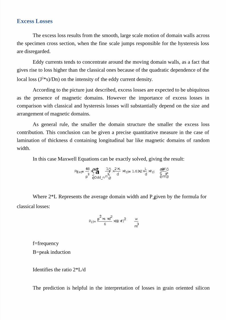
As general rule, the smaller the domain structure the smaller the excess loss
contribution. This conclusion can be given a precise quantitative measure in the case of
lamination of thickness d containing longitudinal bar like magnetic domains of random
width.
In this case Maxwell Equations can be exactly solved, giving the result:
Where 2*L Represents the average domain width and Pcl given by the formula for
classical losses:
f=frequency
B=peak induction
Identifies the ratio 2*L/d
The prediction is helpful in the interpretation of losses in grain oriented silicon
7/25/2019 Transformer's Book a Travel Over Different Aspects of Transformers, Inductors and Transductors - Humberto de So…
http://slidepdf.com/reader/full/transformers-book-a-travel-over-different-aspects-of-transformers-inductors 69/304

7/25/2019 Transformer's Book a Travel Over Different Aspects of Transformers, Inductors and Transductors - Humberto de So…
http://slidepdf.com/reader/full/transformers-book-a-travel-over-different-aspects-of-transformers-inductors 70/304
Facts affecting the total losses
According to the previous explanations an approximate expression for the total power
loss, valid at frequencies low enough to avoid the onset off important eddy current
shielding is:
This equation applies to the particular case of a material magnetized under controlled
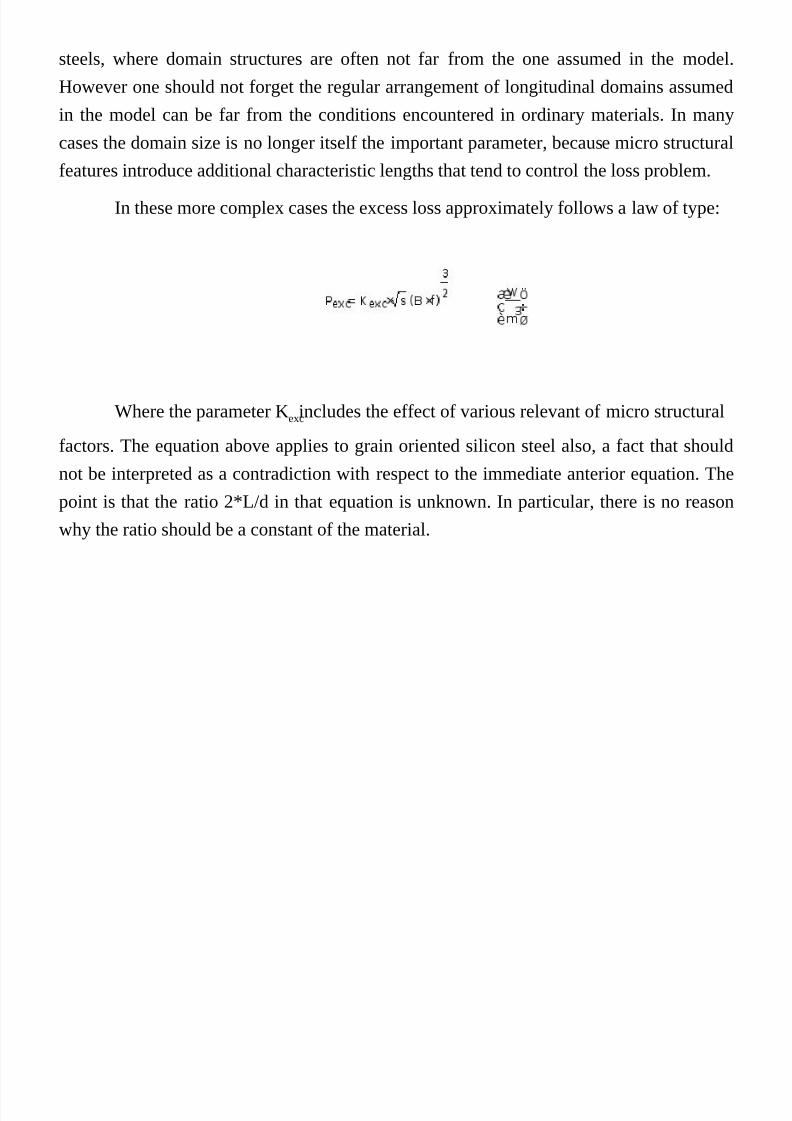
sinusoidal induction rate. However there are several situations where magnetic material
operates under distorted flux conditions, for which a generalization of above is needed.
This generalization is obtained by calculating the instantaneous power loss at individualpoints of the magnetization cycle and then by carrying out the time average over the
particular wave shape involved. This more general expression reads:
Where the arrows are not meaning “vectorize”, but instead time averaging over the
magnetization cycle.
The hysteresis loss is independent of the induction wave-shape , provided the
induction is monotone in each magnetization half-cycle.
7/25/2019 Transformer's Book a Travel Over Different Aspects of Transformers, Inductors and Transductors - Humberto de So…
http://slidepdf.com/reader/full/transformers-book-a-travel-over-different-aspects-of-transformers-inductors 71/304
Loss behavior in different magnetic materials.
The dependence of losses on frequency and induction from the combination of the
three terms of the equation above, the final behavior can be rather different from material
to material. Ferrites, Silicon Iron, Nickel Iron and others, present different amounts of
each of them. Unfortunately the manufactures do not separate their losses, but this is not a
problem because generally they present curves and even coefficients of the Steinmetz
equation.

7/25/2019 Transformer's Book a Travel Over Different Aspects of Transformers, Inductors and Transductors - Humberto de So…
http://slidepdf.com/reader/full/transformers-book-a-travel-over-different-aspects-of-transformers-inductors 72/304
Soft ferrites for high frequency applications:
Most applications at high frequencies up to 100Mhz, leads to the use of soft
ferrites due to their non metallic nature partially avoid eddy current dissipation. In mostapplications, mixed Mn-Zn or Ni-Zn are employed, in which it is possible to tailor
material properties to an specific application by trimming the concentration of the
component atoms.
The electrical resistivity is in the order of 107Wm for Ni-Zn and 10-2 up to 10 Wm
for Zn-Mn ferrites. The initial susceptibility is constant and the loss angle is negligible up
to frequencies of some Mhz to Mn-Zn and 100Mhz for Ni-Zn ferrites.

7/25/2019 Transformer's Book a Travel Over Different Aspects of Transformers, Inductors and Transductors - Humberto de So…
http://slidepdf.com/reader/full/transformers-book-a-travel-over-different-aspects-of-transformers-inductors 73/304
Searching for a general loss model which could include harmonics and
DC currents:
The MSE Approach - (Modified Steinmetz Equation)
Based on the physical understanding as mentioned above that the loss depends of
the average of derivative of the flux density over time [16] we can obtain
Where D B is the peak-to-peak flux amplitude and T is the period of the flux
waveform. From this, an “equivalent frequency” is defined as:
The loss is then estimated with the modified Steinmetz equation (MSE)
Where B is the peak flux density amplitude, PV with the bar on the top meaning
time average of power loss per unit volume and:
Is the repetition frequency.

7/25/2019 Transformer's Book a Travel Over Different Aspects of Transformers, Inductors and Transductors - Humberto de So…
http://slidepdf.com/reader/full/transformers-book-a-travel-over-different-aspects-of-transformers-inductors 74/304
The GSE Approach (General Steinmetz Equation)
The work presented in [17] by Jieli Li, Tarek Abdallah, and Sullivan presents the
approach of the GSE formulation that can be used to calculate loss for any given
waveform:
As presented by the Authors the equation above is the Generalized Steinmetz
equation.
They presented the case where the waveform is sinusoidal, the equation must
behave like the Steinmetz equation for sinusoidal case. For that, they replaced B(t) by a
sinusoidal wave, resulting in:
With:
The integral here is independent of ώ, and so the equation agrees with Steinmetz
equation. But before, we need to get the value of k1 in the equation.
As mentioned and presented by the Authors in their work, the GSE has good
results within determined limits.
Now, we can give a Simulink system that can calculate the GSE presented above.
Firstly we must calculate the value of K1, a and b ,
The values a and b can be taken from the values given by the manufacturer in the
specifications for the ordinary (Sinusoidal) Steinmetz equation. We can calculate K1 from
a given sinusoidal B signal in the input and adjusting K1 in the system fo a same result of
the Steinmetz equation. That is all!
An advantage is that the GSE has a DC-bias sensitivity. A disadvantage of the GSE
is the accuracy limitation if the third or another relatively low-ordered harmonic of the

7/25/2019 Transformer's Book a Travel Over Different Aspects of Transformers, Inductors and Transductors - Humberto de So…
http://slidepdf.com/reader/full/transformers-book-a-travel-over-different-aspects-of-transformers-inductors 75/304
flux density becomes significant, i.e. if multiple peaks are occurring in the flux density
waveform.
To overcome this problem, the GSE was upgraded to the improved Generalized
Steinmetz Equation The AGES splits the waveform in one major and one or more minor
loops and thus takes sub loops of the full hysteresis loop into account. This is
achieved by a recursive algorithm which calculates the iron losses for each loop separately
by
where B is the peak-to-peak flux density of the current major or minor loop of the
waveform.
It should be pointed out that all modifications of the Steinmetz equation have the
well known problem that the Steinmetz coefficients vary with frequency. Thus, forwaveforms with a high harmonic content, it can be difficult to find applicable coefficients
which give good result sover the full frequency range of the applied waveform.

7/25/2019 Transformer's Book a Travel Over Different Aspects of Transformers, Inductors and Transductors - Humberto de So…
http://slidepdf.com/reader/full/transformers-book-a-travel-over-different-aspects-of-transformers-inductors 76/304
Combination of fields

7/25/2019 Transformer's Book a Travel Over Different Aspects of Transformers, Inductors and Transductors - Humberto de So…
http://slidepdf.com/reader/full/transformers-book-a-travel-over-different-aspects-of-transformers-inductors 77/304
Ampere´s Law in depth.
Fig. 30 The representation of the Apere´s Law
The current in a conductor always creates a magnetic field around it with the
intensity of 1.25 Oersted for each Amp/cm.
A tangential field to a conductor generates current in it. They are fundamentally
interrelated, generating one, intrinsically creates another (Inter-causality).
Practical Example:
In a plier’s ammeter, the current is measured by the intensity of the magnetic field,
no matter the size of the pickup ring instrument which is around the conductor.
The current is measured, only in the conductor that is going through inside of the
pickup ring.

7/25/2019 Transformer's Book a Travel Over Different Aspects of Transformers, Inductors and Transductors - Humberto de So…
http://slidepdf.com/reader/full/transformers-book-a-travel-over-different-aspects-of-transformers-inductors 78/304
For the Sake of simplicity
To simplify the analysis, we will establish the hypothesis of an infinite height
Planar Conductor with a flat field on their faces. This assumption of course, is a
simplification of the effect, do not existing in practice, however, serving for the present
purposes and not introducing any misconception. In reality the field decays while going
away from the conductor.

7/25/2019 Transformer's Book a Travel Over Different Aspects of Transformers, Inductors and Transductors - Humberto de So…
http://slidepdf.com/reader/full/transformers-book-a-travel-over-different-aspects-of-transformers-inductors 79/304
Magnetic field produced by currents in endless sheets
As will be shown in the following figure, an uniform current in an infinite plate,
produces a uniform field on each side of the sheet, but with opposite polarities. A current
density of 1A / Cm generates a field of 0.628 Oersted on each face. With m =1, B=
(Gauss), H (Oersted)
In a real conductor, the field quickly decays as it leaves the conductor but in our
hypothetical infinite sheet, remains constant.
The creation of this model, aims to simplify the understanding of the combinations
of the fields in different configurations, avoiding the detailed description of its variations.
The main objective is to be able to show the different interactions between themagnetic fields that result from combinations of windings in various structures.
Minor differences in decay in the spaces for these representations show no
significant deviations when compared to real models, and its real conceptual goal is the
representation of all the interactions between fields in a more simple way.
Besides, this book is not intended to be a matter for beginners, but a source of
information for experienced designers. The subjects contained in this book, are far of
being information found in any common book of transformers. Due to this fact, we feel
ourselves very free to make such suppositions, considering that the reader would not make
absurd considerations about the subjects being approached.
Fig. 31 Suposition of an infinite bar surrounded by a magnetic field

7/25/2019 Transformer's Book a Travel Over Different Aspects of Transformers, Inductors and Transductors - Humberto de So…
http://slidepdf.com/reader/full/transformers-book-a-travel-over-different-aspects-of-transformers-inductors 80/304
Fig. 32 The direction of the fiel obeys the right hand rule
7/25/2019 Transformer's Book a Travel Over Different Aspects of Transformers, Inductors and Transductors - Humberto de So…
http://slidepdf.com/reader/full/transformers-book-a-travel-over-different-aspects-of-transformers-inductors 81/304
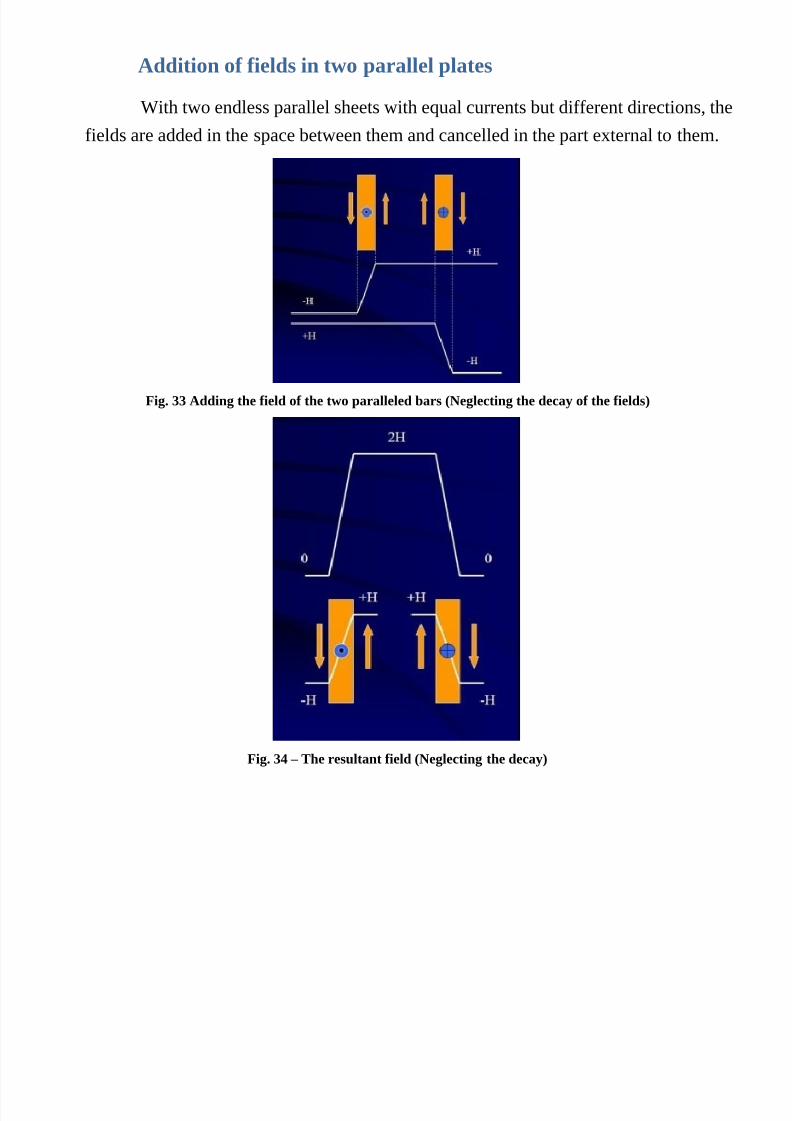
Addition of fields in two parallel plates
With two endless parallel sheets with equal currents but different directions, the
fields are added in the space between them and cancelled in the part external to them.
Fig. 33 Adding the field of the two paralleled bars (Neglecting the decay of the fields)
Fig. 34 – The resultant field (Neglecting the decay)

7/25/2019 Transformer's Book a Travel Over Different Aspects of Transformers, Inductors and Transductors - Humberto de So…
http://slidepdf.com/reader/full/transformers-book-a-travel-over-different-aspects-of-transformers-inductors 82/304
Infinite Solenoid
This distribution field, does not change when we join the sheets to allow
current to flow in a continuous loop.
This forms the classical non finite length solenoid in which the flow is uniform
inside and on the outside is zero
Fig. 35
If the solenoid consisting of a coil rather than a sheet, then:

7/25/2019 Transformer's Book a Travel Over Different Aspects of Transformers, Inductors and Transductors - Humberto de So…
http://slidepdf.com/reader/full/transformers-book-a-travel-over-different-aspects-of-transformers-inductors 83/304
Fig. 36 – If the coil has two layers the interaction of the fields can be seen.
Fig. 37 – Flux = 0 outside and H inside

7/25/2019 Transformer's Book a Travel Over Different Aspects of Transformers, Inductors and Transductors - Humberto de So…
http://slidepdf.com/reader/full/transformers-book-a-travel-over-different-aspects-of-transformers-inductors 84/304
Addition of fields in several layers:
Two overlapping solenoids
As a solenoid is on top of another, the field of each solenoid is added to the field
formed by the previous. Thus we have over the first solenoid H = 0, on top of the second
solenoid H = 1 on the third solenoid H = 2 and beneath the third solenoid H = 3.
Fig. 38
We can see that inside the solenoid H=2;
Fig. 39
We can see that inside the solenoid H=3
Permeability:
Relutance:

7/25/2019 Transformer's Book a Travel Over Different Aspects of Transformers, Inductors and Transductors - Humberto de So…
http://slidepdf.com/reader/full/transformers-book-a-travel-over-different-aspects-of-transformers-inductors 85/304
In reality, the magnetic core may be of ferrite, iron, or metal composition, their
internal fields depends solely of the reluctance, and H Field manipulated by the solenoid.
In transformers, the secondary current produces an “H field comparison thatinduces a counter current in the primary winding (as defined by Lenz’s law), and this
additional field, does not contribute to the core flux.
We can call this phenomenon “countercurrent confrontation “and the fields
produced by the primary and secondary are the same, the only difference being the H field
necessary for the magnetization of the core.
Np=Number of Turns
Ip=Current of Primary
Ns=Number of turns of Secondary
Is=current of secondary
The above relationship provides relation of currents in a transformer:
In transformers with adjacent primary and secondary, the MMF distribution
depends only on the relative arrangements between them. The overall curvatures are
irrelevant, as well as their position in the core.
In inductors, MMF produced by the current is absorbed or “confronted” by the
reluctance of core instead of “countercurrent confrontation ” of another winding. Thus,
(portions of high reluctance) of the core relative to the winding diagram determine the
FMM profile.

7/25/2019 Transformer's Book a Travel Over Different Aspects of Transformers, Inductors and Transductors - Humberto de So…
http://slidepdf.com/reader/full/transformers-book-a-travel-over-different-aspects-of-transformers-inductors 86/304
Fig. 40
Note that the core is shaped like a pot, and the axis the dotted line ending below in the “C”
inside the square. The same pattern will be repeated to the right from the center.
The more reddish shows the increase in the H field toward the high reluctance
element (low permeability).
Note that we are advancing very slowly with the intention to fix very well the
concepts involved in the combination of fields. This is a part of my course of transformers
Fig. 41 Evolution of MMF (H Field) diagram due to low mu material in both sides
Fig. 42 Evolution of MMF diagram due to low mu material at right

7/25/2019 Transformer's Book a Travel Over Different Aspects of Transformers, Inductors and Transductors - Humberto de So…
http://slidepdf.com/reader/full/transformers-book-a-travel-over-different-aspects-of-transformers-inductors 87/304
Low m material (High reluctance) in the top side of the core.
Fig. 43Evolution of H Field due to low mu material at the top
Low mu material (High reluctance) in the top and in the bottom side of the core.
We can see very clear that the mmf (H) diagrams grows toward the low magnetic
material (Higher reluctance).
Fig. 44

7/25/2019 Transformer's Book a Travel Over Different Aspects of Transformers, Inductors and Transductors - Humberto de So…
http://slidepdf.com/reader/full/transformers-book-a-travel-over-different-aspects-of-transformers-inductors 88/304
Simulation by FEA (Finite Element Analysis)
On a core ‘E’ “curled up a primary and a secondary winding, passing cross
currents” I “in each. Each coil has 3 layers and currents are equal. The core is of silicon-
Iron sheet. There is no concern for the flux in the core.
This research is going to be done in FEMM.
Simulation by FEA (Finite Elements Analysis by FEMM
We use the FEMM because it is very powerfull and can analise skin depth
problems and in addition can be found in Tnternet totally free.
The software was developed by David Meeker, Ph.D and is in the words of it´s
own author:A Windows finite element solver for 2D and axisymmetric magnetic, electrostatic, heat flow, and
current flow problems with graphical pre- and post-processors.
Is a very powerfull tool and can be foun at Internet in:
http://www.femm.info/wiki/HomePage
Other parts of the software like the Triangle was developed in Computer Sciencedivision at Uinversity of California at Berkeley and the software LUA, developed inPontifícia Universidade Católica do Rio de Janeiro – Brasil.
Fig. 45 Can be seen the regions and the setting of materials and the definition of air spaces.
Although the differential equations that describe magnetic phenomena in
transformers (And other magnetic components), are relatively compact, it is very difficult
to get closed solutions, except for extremely simple geometries. Here is where the idea of

7/25/2019 Transformer's Book a Travel Over Different Aspects of Transformers, Inductors and Transductors - Humberto de So…
http://slidepdf.com/reader/full/transformers-book-a-travel-over-different-aspects-of-transformers-inductors 89/304
finite elements breaks the problem of complex geometries in a large number of simple
structural elements, for example triangles. The process solution is reduced through simple
geometries.
The advantage of breaking the complex geometry in a large number of simple
elements, it is that turned a small problem, but difficult to solve in a big problem, but of
relatively simple solution. Specifically the triangulation serves this purpose, as the case
that reduces to a simple linear algebra solution with perhaps tens of thousands of
unknowns
The FEMM uses triangular elements. About each element, the solution is
approximated by linear interpolation of the values of the three vertices of the triangle. The
linear algebra problem is formed by the choice of A based on the minimization of the total
energy.
Triangulating …
Fig. 46 – The mesh of triangles is generated by the software
Fig. 47 – Now we can see a closed view of the definitions of material and the mesh of triangles

7/25/2019 Transformer's Book a Travel Over Different Aspects of Transformers, Inductors and Transductors - Humberto de So…
http://slidepdf.com/reader/full/transformers-book-a-travel-over-different-aspects-of-transformers-inductors 90/304
Solving the model:
Fig. 48 – The flux seen at distance
The figure below, show the contours of the magnetic strength H in the window of
the transformer.
Fig. 49 The field strength lines
The red line at left define the path where we will measure the H field.

7/25/2019 Transformer's Book a Travel Over Different Aspects of Transformers, Inductors and Transductors - Humberto de So…
http://slidepdf.com/reader/full/transformers-book-a-travel-over-different-aspects-of-transformers-inductors 91/304
Fig. 50 – Path for definition of the H field
Calculating the field H over the path:
Fig. 51 – H field over the path
This is behaving exactly as we have seen in fig 36.
We can see the evolution of H, rising to as it approaches the secondary, reaching
the maximum amplitude and reducing from there. Note clearly, the effect of the “counter
current”.
The energy in the windings is proportional to the square of the magnetic field (H2
).
Note that the H2 is directly related to the energy of the magnetic field and is a
valuable measure of the energy stored in the volume of the entire coil.

7/25/2019 Transformer's Book a Travel Over Different Aspects of Transformers, Inductors and Transductors - Humberto de So…
http://slidepdf.com/reader/full/transformers-book-a-travel-over-different-aspects-of-transformers-inductors 92/304
We can see the total energy per unit area by measuring the magnetic energy
contained in the window of the transformer. The Finite elements software is a valuable
tool in order to get this value.
Defining an area where we will measure the energy of the magnetic field.
This will be done within the primary windingregion (Marked in green)
Fig. 52 The area of measurement was defined by the color green
Fig. 53 – The kind of measurement is selected (Magnetic field Energy
After solution…
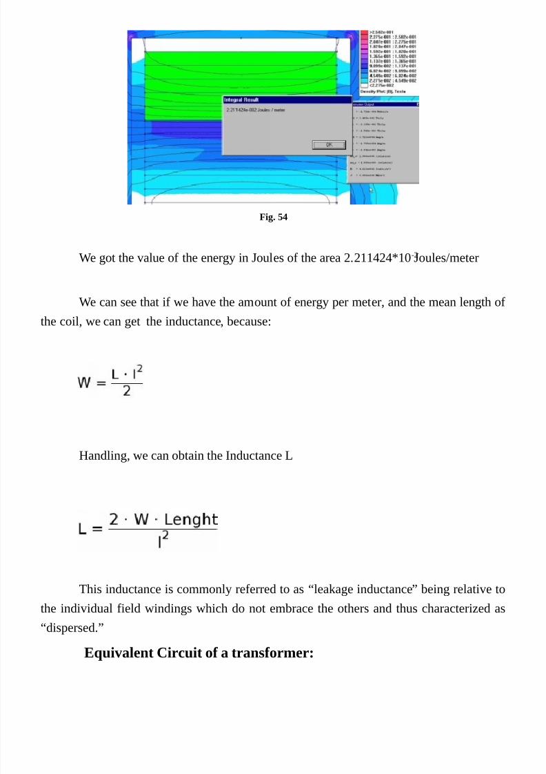
7/25/2019 Transformer's Book a Travel Over Different Aspects of Transformers, Inductors and Transductors - Humberto de So…
http://slidepdf.com/reader/full/transformers-book-a-travel-over-different-aspects-of-transformers-inductors 93/304
Fig. 54
We got the value of the energy in Joules of the area 2.211424*10-2 Joules/meter
We can see that if we have the amount of energy per meter, and the mean length of
the coil, we can get the inductance, because:
Handling, we can obtain the Inductance L
This inductance is commonly referred to as “leakage inductance” being relative to
the individual field windings which do not embrace the others and thus characterized as
“dispersed.”
Equivalent Circuit of a transformer:

7/25/2019 Transformer's Book a Travel Over Different Aspects of Transformers, Inductors and Transductors - Humberto de So…
http://slidepdf.com/reader/full/transformers-book-a-travel-over-different-aspects-of-transformers-inductors 94/304
Fig. 55 – The equivalent diagram considering the turns relation n between prim and sec = 1
Ldp=Leakage inductance related to the primary
Rp=Core loss related to the primary
Lm=Mutual Inductance Related to the primary
Rsec=Resistance of the winding of the secondary
Lds=Leakage inductance related to the secondary

7/25/2019 Transformer's Book a Travel Over Different Aspects of Transformers, Inductors and Transductors - Humberto de So…
http://slidepdf.com/reader/full/transformers-book-a-travel-over-different-aspects-of-transformers-inductors 95/304
Leakage Inductance
What is leakage Inductance
The definition of a fundamental inductance equation departing
from the energy stored in magnetic field:For considerations of leakage inductance due to a particular layer, it is only
necessary to consider the other winding layers which influence in it.
The distribution of leakage flux through any layer depends only on its current and
summation of the currents of the layers that lay between it and the layer which is adjacent
to MMF zero position. For leakage inductance analysis purposes, we should consider the
spaces of winding layers as parts that lie between zero and the maximum field. To these
parts we will call “Portion”.
Fig. 56 – Definition of “Portion”
Fig. 57 Portion in interleaved coils
As a result of interleaving windings, we have a reduction of amplitudes of the
magnetic fields in the transformer. Consequently we can drastically reduce the leakage
inductance.

7/25/2019 Transformer's Book a Travel Over Different Aspects of Transformers, Inductors and Transductors - Humberto de So…
http://slidepdf.com/reader/full/transformers-book-a-travel-over-different-aspects-of-transformers-inductors 96/304
The density of the energy in the magnetic field is:
And the total energy field with constant density in a given volume is:
W
At this point the flux density B is merely the current in the windings multiplied by
the permeability of vacuum, number of Turns of coils, etc … and is not the flux density
present in the core (determined by the effective cross-sectional area, voltage, frequency,
etc.)
If the field is not homogeneous, this relationship can be applied to all units of
infinitesimal volume and the total energy can be determined by integration:
If we combine with the relations:
We get:
That we can call “Inductance general equation”
Inductance formula definition (Toroidal Case):Initially we will determine the formula of inductance of an inductor with toroidal
core. Additionally we will determine the formula for the leakage inductance of a

7/25/2019 Transformer's Book a Travel Over Different Aspects of Transformers, Inductors and Transductors - Humberto de So…
http://slidepdf.com/reader/full/transformers-book-a-travel-over-different-aspects-of-transformers-inductors 97/304
transformer
As in a toroidal Core the field is homogeneous we can calculate de volume of the
Core simply by:
Replacing V:
At present case de measures are in Centimeters.
We have:
Replacing H2, We have:

7/25/2019 Transformer's Book a Travel Over Different Aspects of Transformers, Inductors and Transductors - Humberto de So…
http://slidepdf.com/reader/full/transformers-book-a-travel-over-different-aspects-of-transformers-inductors 98/304
Simplifying:
~
Introducing the relative permeability, we get:
Inductance Formula definition (Leakage inductance Case):
Fig. 58

7/25/2019 Transformer's Book a Travel Over Different Aspects of Transformers, Inductors and Transductors - Humberto de So…
http://slidepdf.com/reader/full/transformers-book-a-travel-over-different-aspects-of-transformers-inductors 99/304
Fig. 59 - Circular coil for the determination of the leakage inductance equation
Equation of general inductance arranged for circular winding. In this way we arechanging dv by dr, then rearranging:
Soon:
Finally:
Decomposition of the Equation illustrating the elements of the leakage inductance:
Primary Leakage Inductance:

7/25/2019 Transformer's Book a Travel Over Different Aspects of Transformers, Inductors and Transductors - Humberto de So…
http://slidepdf.com/reader/full/transformers-book-a-travel-over-different-aspects-of-transformers-inductors 100/304
Secondary Leakage Inductance:
Contribution of the Intersection gap:
It is common practice to be considered the contribution of the intersection gaps as
part of the primary leakage inductance, however, this depends on the settings, primaries
and secondaries, number of layers and etc
Fig. 60 – Account of the intersection gaps
The inductance of the gap is due to the local field. ASimple way to treat the
problem, is to check the proportion of the field that acts on that layer are relative to the
total field, creating the proportionality constant k For each intersection gap.
The total leakage inductance is the contribution given by inductances of the
layers plus the contribution given by spaces (intersection Gaps).
Ltot=L cam(1) +…L cam(n) +L inter(1) +…L inter(n)

7/25/2019 Transformer's Book a Travel Over Different Aspects of Transformers, Inductors and Transductors - Humberto de So…
http://slidepdf.com/reader/full/transformers-book-a-travel-over-different-aspects-of-transformers-inductors 101/304
Fig. 61 The null field spaces
We should note that the spaces that are experiencing null fields should not be taken
into consideration because it does not contribute to the total energy.
This is the case of the previous slide, where we have the field H = 0 in the inter-
section of gap between secondary 1 and primary 2.
Applying the same principle:
Solving:
Doing Eprim1=Eprim2=Eprim e Esec1=Esec2=Esec, We Have:

7/25/2019 Transformer's Book a Travel Over Different Aspects of Transformers, Inductors and Transductors - Humberto de So…
http://slidepdf.com/reader/full/transformers-book-a-travel-over-different-aspects-of-transformers-inductors 102/304
That simplifying finally crops:
Final Formula:
Where:
Dm=Average diameter of the coil
L=Length of the coil
N = Number of the turns of that coil.
Eprim and Esec = Height of primary and secondary coils respectively.
S1 e S3 width of gap space between coils
We can note Ldp and Lds as the dispersion inductances on the primary andsecondary. These inductances are in series with the resistance of the primary and
secondary (Rprim and rsec). The mutual inductance and loss resistance (Lm and Rp) are
part of the diagram, but they are out of our present interest.
With the inductance general equation, we are free to define (deduce) any formula
for any arrangement of coils, to calculate the stray (Dispersion) inductances. We need only
arrange the problem strategically to solve the particular problem.

7/25/2019 Transformer's Book a Travel Over Different Aspects of Transformers, Inductors and Transductors - Humberto de So…
http://slidepdf.com/reader/full/transformers-book-a-travel-over-different-aspects-of-transformers-inductors 103/304
The equivalent circuit of a transformer and
measurements of AC Resistance:

7/25/2019 Transformer's Book a Travel Over Different Aspects of Transformers, Inductors and Transductors - Humberto de So…
http://slidepdf.com/reader/full/transformers-book-a-travel-over-different-aspects-of-transformers-inductors 104/304
The equivalent circuit:
As defined in the anterior chapter a transformer has a general equivalent circuit
like presented Below in which we now add a load Z.
The general transfer function to it, using chain matrix is:
Solving:

7/25/2019 Transformer's Book a Travel Over Different Aspects of Transformers, Inductors and Transductors - Humberto de So…
http://slidepdf.com/reader/full/transformers-book-a-travel-over-different-aspects-of-transformers-inductors 105/304
AC resistance Measurement
For the first work we must to measure the input impedance with output short
circuited. The effect of Zm will be neglected and we can do it infinite impedance. Thus
considering this, our expression change to:
Zin is:
Consider that the turn’s relation n, must be taken into consideration to the proper
reflection of Zsec to the primary.
For the measurement of the AC resistance, we must connect the secondary in short
circuit, injecting in the primary ac voltage or current, measuring the active power.
The measurement instrument must have a wide band to assure precision . A
digital oscilloscope would be a good choice.
With the power and the current measured, we can calculate the value of the total
AC resistance for the given frequency (That of measurement).
A precise impedance bridge can be used for this measurement and also we can
directly measure the dispersion inductance of primary and secondary. There are
impedance bridges with various measurement frequencies that would be useful in our
testing’s.

7/25/2019 Transformer's Book a Travel Over Different Aspects of Transformers, Inductors and Transductors - Humberto de So…
http://slidepdf.com/reader/full/transformers-book-a-travel-over-different-aspects-of-transformers-inductors 106/304
Measurement of DC resistance
For the measurement of the DC resistance a Thomson bridge that works in Direct
Current is the correct choice. There are other instruments with four terminals for
measurement of DC resistance that guarantee good precision.
This same chosen instrument will be used in the transformer temperature tests,
elsewhere in this book.

7/25/2019 Transformer's Book a Travel Over Different Aspects of Transformers, Inductors and Transductors - Humberto de So…
http://slidepdf.com/reader/full/transformers-book-a-travel-over-different-aspects-of-transformers-inductors 107/304
High frequencies response:
For High frequency, is customary introduce the stray capacitance in the output of
the transformer, but the Zm in this case also, is considered virtually infinite. Then, our
complete matrix change to:
The transfer function:
Considering that:

7/25/2019 Transformer's Book a Travel Over Different Aspects of Transformers, Inductors and Transductors - Humberto de So…
http://slidepdf.com/reader/full/transformers-book-a-travel-over-different-aspects-of-transformers-inductors 108/304
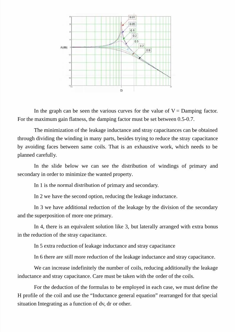
7/25/2019 Transformer's Book a Travel Over Different Aspects of Transformers, Inductors and Transductors - Humberto de So…
http://slidepdf.com/reader/full/transformers-book-a-travel-over-different-aspects-of-transformers-inductors 109/304
In the graph can be seen the various curves for the value of V = Damping factor.For the maximum gain flatness, the damping factor must be set between 0.5-0.7.
The minimization of the leakage inductance and stray capacitances can be obtained
through dividing the winding in many parts, besides trying to reduce the stray capacitance
by avoiding faces between same coils. That is an exhaustive work, which needs to be
planned carefully.
In the slide below we can see the distribution of windings of primary and
secondary in order to minimize the wanted property.
In 1 is the normal distribution of primary and secondary.
In 2 we have the second option, reducing the leakage inductance.
In 3 we have additional reduction of the leakage by the division of the secondary
and the superposition of more one primary.
In 4, there is an equivalent solution like 3, but laterally arranged with extra bonusin the reduction of the stray capacitance.
In 5 extra reduction of leakage inductance and stray capacitance
In 6 there are still more reduction of the leakage inductance and stray capacitance.
We can increase indefinitely the number of coils, reducing additionally the leakage
inductance and stray capacitance. Care must be taken with the order of the coils.
For the deduction of the formulas to be employed in each case, we must define the
H profile of the coil and use the “Inductance general equation” rearranged for that special
situation Integrating as a function of dv, dr or other.

7/25/2019 Transformer's Book a Travel Over Different Aspects of Transformers, Inductors and Transductors - Humberto de So…
http://slidepdf.com/reader/full/transformers-book-a-travel-over-different-aspects-of-transformers-inductors 110/304

7/25/2019 Transformer's Book a Travel Over Different Aspects of Transformers, Inductors and Transductors - Humberto de So…
http://slidepdf.com/reader/full/transformers-book-a-travel-over-different-aspects-of-transformers-inductors 111/304
Medium frequencies Response
For this condition, the complete equation will be used:
The transfer function would be:
Where:
Due to other considerations the power factor of the Zload can be added for a more
correct response of the system.

7/25/2019 Transformer's Book a Travel Over Different Aspects of Transformers, Inductors and Transductors - Humberto de So…
http://slidepdf.com/reader/full/transformers-book-a-travel-over-different-aspects-of-transformers-inductors 112/304
Low frequencies response
Evidently the transformer is not intended to work below its operating frequency,
but in certain cases, certain classes of transformers need transiently to work in very lowfrequencies, like instrumentation transformers and so forth.
With the decreasing of frequency, the transformer is lead to the short circuit or
something near that, when frequency approaches 0.
We must consider the impedance of the generator to compute the real frequency
response, manly in applications of audio amplifiers or instrumentation. Someone can smile
or even To laugh when hearing about transformers to audio amplifiers, but still today thebest of the best of audio amplifier use Vacuum Tubes and transformers. Vacuum tubes and
transformers working besides last generation DSP, wireless and so forth. Is incredible but
it’s true. The transistors with their non linear natures are very strange in audio
environment. The feedback is improper to correct inter modulation products and other
transients generated in the nonlinearities and dynamic properties of such amplifiers.
We can modify our equation to work with generator impedance, considering that
the Zprim and Zsec are Zero, reducing our equation, and we get:
Where:

7/25/2019 Transformer's Book a Travel Over Different Aspects of Transformers, Inductors and Transductors - Humberto de So…
http://slidepdf.com/reader/full/transformers-book-a-travel-over-different-aspects-of-transformers-inductors 113/304

7/25/2019 Transformer's Book a Travel Over Different Aspects of Transformers, Inductors and Transductors - Humberto de So…
http://slidepdf.com/reader/full/transformers-book-a-travel-over-different-aspects-of-transformers-inductors 114/304
Skin Depth and Proximity Effect

7/25/2019 Transformer's Book a Travel Over Different Aspects of Transformers, Inductors and Transductors - Humberto de So…
http://slidepdf.com/reader/full/transformers-book-a-travel-over-different-aspects-of-transformers-inductors 115/304
Skin Depth
Ampere Law in more Detail:
The surface current in a conductor always creates a magnetic field around it
It can be said that a tangential field to a conductor generates this surface current.
They are fundamentally related, generating one inherently creates another (Inter
causal)
This may seem counterintuitive therefore a magnet placed on a conductive plate do
not creates a perpetual flow of current (except in a superconductor).
To understand the principle on which a field always has a corresponding surfacecurrent, it requires that we analyze how surface currents evolve over time.
We are assuming that this matter in most cases is not of full reader’s knowledge
and thus we are going to present it step by step in order to make it the most clearly
possible.

7/25/2019 Transformer's Book a Travel Over Different Aspects of Transformers, Inductors and Transductors - Humberto de So…
http://slidepdf.com/reader/full/transformers-book-a-travel-over-different-aspects-of-transformers-inductors 116/304
Diffusion of magnetic field in a Conductor
If a magnetic field “H” is suddenly generated at = 0 in the neighborhood of a
conductive plate. A corresponding surface current will flow in the conductor perpendicular
to the field (right hand rule). Resistive effects quickly try to reduce this surface current,
allowing the magnetic field penetrating the short distance in the conductor. By the fact, inthe ampere law the current and field are inter causal, if a conductor is subjected to a
sudden current, the diffusion chain will also be gradual, starting from the outer surface
toward the inside
Fig. 62
The current now flows at a finite depth in the conductor. The IxR resistive drops
are smaller but still present, and the magnetic field continues to spread toward the inside
of the conductor. But at a lower rate. As the surface current will gradually gaining a larger
flow area, the magnetic field diffusion rate reduces its speed to the square root of the time
(t = 1,4,16, etc.).
Eventually the field reaches the opposite surface where the field now develops.
Since then the total current begins to decrease as comes into being an oppositesurface current on the other side of the conductor, who now has the same magnetic field,
until t = infinity when the current will be zero.

7/25/2019 Transformer's Book a Travel Over Different Aspects of Transformers, Inductors and Transductors - Humberto de So…
http://slidepdf.com/reader/full/transformers-book-a-travel-over-different-aspects-of-transformers-inductors 117/304
Fig. 63

7/25/2019 Transformer's Book a Travel Over Different Aspects of Transformers, Inductors and Transductors - Humberto de So…
http://slidepdf.com/reader/full/transformers-book-a-travel-over-different-aspects-of-transformers-inductors 118/304
Simple Rules in order to handle fields and currents in a single
face.
(Follows the right hand rule)

7/25/2019 Transformer's Book a Travel Over Different Aspects of Transformers, Inductors and Transductors - Humberto de So…
http://slidepdf.com/reader/full/transformers-book-a-travel-over-different-aspects-of-transformers-inductors 119/304
Direction of the current
Fig. 64
Simple Rules
Fig. 65 Field towards up in the right side
Fig. 66 Field Towards up in the left side
Fig. 67 Field towards down in the left side

7/25/2019 Transformer's Book a Travel Over Different Aspects of Transformers, Inductors and Transductors - Humberto de So…
http://slidepdf.com/reader/full/transformers-book-a-travel-over-different-aspects-of-transformers-inductors 120/304
Fig. 68 Field towards down in the right side
If a conductor is suddenly subjected to a homogeneous field
will be formed two films that will gradually grow toward the inside of the
conductor as shown in the following figure.
Fig. 69 Field suddenly subjected by an homogeneous field
Note that the current gradual diffusion is contrary, according to the directions of
the fields on both sides of the bar.
Fig. 70 The difusing in both directions
For t = Infinite the currents will be diffusing across the bar equally in both
directions, canceling each other. Therefore the final resulting current is zero.
Looking from another angle, bar dipped in a homogeneous field shows no
electrical potential, as described by the Faraday Law, where the time variation of the field
is required to produce voltage potential.
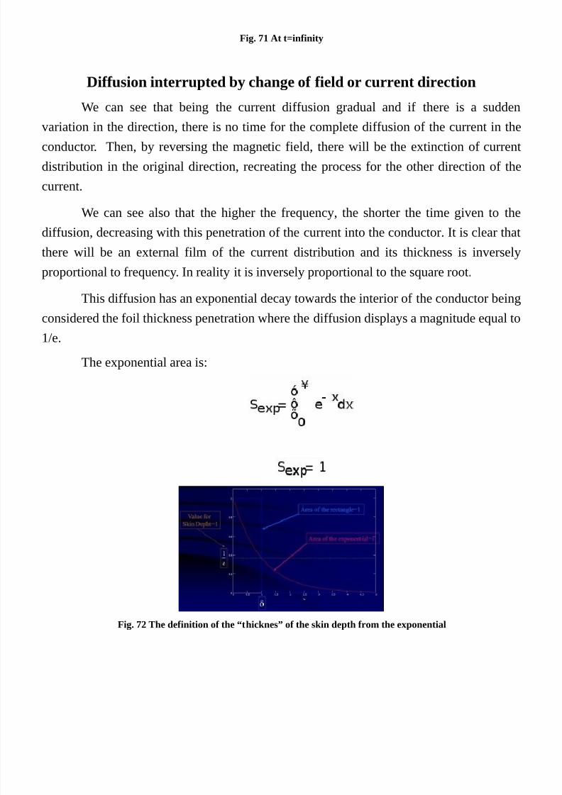
7/25/2019 Transformer's Book a Travel Over Different Aspects of Transformers, Inductors and Transductors - Humberto de So…
http://slidepdf.com/reader/full/transformers-book-a-travel-over-different-aspects-of-transformers-inductors 121/304
Fig. 71 At t=infinity
Diffusion interrupted by change of field or current direction
We can see that being the current diffusion gradual and if there is a sudden
variation in the direction, there is no time for the complete diffusion of the current in the
conductor. Then, by reversing the magnetic field, there will be the extinction of current
distribution in the original direction, recreating the process for the other direction of the
current.
We can see also that the higher the frequency, the shorter the time given to the
diffusion, decreasing with this penetration of the current into the conductor. It is clear that
there will be an external film of the current distribution and its thickness is inversely
proportional to frequency. In reality it is inversely proportional to the square root.
This diffusion has an exponential decay towards the interior of the conductor being
considered the foil thickness penetration where the diffusion displays a magnitude equal to
1/e.
The exponential area is:
Fig. 72 The definition of the “thicknes” of the skin depth from the exponential

7/25/2019 Transformer's Book a Travel Over Different Aspects of Transformers, Inductors and Transductors - Humberto de So…
http://slidepdf.com/reader/full/transformers-book-a-travel-over-different-aspects-of-transformers-inductors 122/304
Fig. 73 The logaritimic exponential
The instantaneous current is also delayed of one radian per deepening of the skin,thus the vector of AC current forms a logarithmic spiral, as was shown in the previous
figure.
Fig. 74 - Current diffusion in a circular conductor
Fig. 75 The exponential diffusion

7/25/2019 Transformer's Book a Travel Over Different Aspects of Transformers, Inductors and Transductors - Humberto de So…
http://slidepdf.com/reader/full/transformers-book-a-travel-over-different-aspects-of-transformers-inductors 123/304
Fig. 76 Considering the skin depth of the circular wire, working like a circular pipe
It can be seen in the figure above the distribution of field in a conductor for an
alternating current with a given frequency.
Skin Depth
Where:
μo= Vacuum permeability.
μr=Conductorpermeability.
f = Frequency in Hertz.
λ =Wavelength of the frequency.
C= Speed of light in Vacuum.

7/25/2019 Transformer's Book a Travel Over Different Aspects of Transformers, Inductors and Transductors - Humberto de So…
http://slidepdf.com/reader/full/transformers-book-a-travel-over-different-aspects-of-transformers-inductors 124/304
Fig. 77 – Main constants and values of the temperatures
Calculation of resistivity of copper for each
temperature
Fig. 78 – Resistivity as a function of temperature and resistivity at each temperature
Values of “Constanted” for Copper and Aluminum in function of temperatures

7/25/2019 Transformer's Book a Travel Over Different Aspects of Transformers, Inductors and Transductors - Humberto de So…
http://slidepdf.com/reader/full/transformers-book-a-travel-over-different-aspects-of-transformers-inductors 125/304
Fig. 79 Constants of Cu and Al at each temperature

7/25/2019 Transformer's Book a Travel Over Different Aspects of Transformers, Inductors and Transductors - Humberto de So…
http://slidepdf.com/reader/full/transformers-book-a-travel-over-different-aspects-of-transformers-inductors 126/304
Proximity Effect:
Fig. 80 the diffusion of current depending the relative direction of conductors
In both conductors of the next slide, we can see the spacing and alignment of
greater diffusion regions, depending evidently the relative direction of the currents.
This effect is known as “proximity effect” because it involves effects due to
proximity of conductors and fields.
Fig. 81 currents in same direction
Fig. 82 Currents in opposite directions
Proximity & Skin Effect
The proximity effect in parallel conductors are combined with the skin effect,

7/25/2019 Transformer's Book a Travel Over Different Aspects of Transformers, Inductors and Transductors - Humberto de So…
http://slidepdf.com/reader/full/transformers-book-a-travel-over-different-aspects-of-transformers-inductors 127/304
generating a rather much more complex effect what is known as “Skin proximity effect”,
most wrongly mentioned in the literature as “proximity effect“.
The proximity effect is dominant over the classic skin effects in windings of high
frequency or high current in magnetic components (Transformers, Inductors or
transductors).
Ordinary proximity effect is combined with the skin properties of the current,
creating a combined effect notoriously difficult to be calculated, especially when it
involves multiple conductors.
The proximity effect develops considerable losses.
In extreme cases proximity effect losses may involve tens, hundreds and
sometimes thousands of times greater losses than the direct current.
Proximity Effect three-dimensional configurations.
Three-dimensional configurations are effectively one-dimensional when they are
contained in two of three dimensions. An isolated round wire is a case: Due to symmetry,
the currents and fields vary radially in cylindrical coordinates, with no axial or
circumferential variations.
This symmetry is destroyed with two wires, and the complexity grows with the
number of conductors and their consequent interactions.
There were no practical formulas available to calculate these phenomena in
windings of transformers and conventional inductors, until the advent of Dowell work.
Simplifying assumptions
•
The layers of windings are assumed to homogeneous conductive plates.
• The layers of windings are considered infinitely long portions of a coaxialsolenoid (The flow is uniform anywhere and axially between the layers).
• The thickness of the layers is much smaller than the radius of curvature (may
be analyzed locally as a flat plate portion).
• All the coils have the same distance (No partial layers).
• All layers on a winding portion have the same thickness.
Consequences:
•
These assumptions reduce the problem to one dimension; Currents and fields

7/25/2019 Transformer's Book a Travel Over Different Aspects of Transformers, Inductors and Transductors - Humberto de So…
http://slidepdf.com/reader/full/transformers-book-a-travel-over-different-aspects-of-transformers-inductors 128/304
vary only radially. Not varying axially or circumferentially. Similarly to the case of
a circular isolated conductor.

7/25/2019 Transformer's Book a Travel Over Different Aspects of Transformers, Inductors and Transductors - Humberto de So…
http://slidepdf.com/reader/full/transformers-book-a-travel-over-different-aspects-of-transformers-inductors 129/304
Transformation from a round conductor winding to metal plate
or sheet
Dowell transformed circular wire windings into an “Equivalent
Sheet” as follows.
• First replaces round wires by squares of equal areas.
• After join the squares by moving them.
•
After stretch it to cover the previous distance.
•
The new thickness “h” is equal to the plate thickness of the square of the
conductive plate and the resistivity is increased by a factor s /h in order to
maintain the same resistance.
Fig. 83 Sequence of transformation from round conductors to sheet - Dowell
Fig. 84

7/25/2019 Transformer's Book a Travel Over Different Aspects of Transformers, Inductors and Transductors - Humberto de So…
http://slidepdf.com/reader/full/transformers-book-a-travel-over-different-aspects-of-transformers-inductors 130/304
Fig. 85 Bar conductors
We can see right the highlight showing the exponential decay of the current
distribution in the conductor bar
Fig. 86 - Sheet conductor

7/25/2019 Transformer's Book a Travel Over Different Aspects of Transformers, Inductors and Transductors - Humberto de So…
http://slidepdf.com/reader/full/transformers-book-a-travel-over-different-aspects-of-transformers-inductors 131/304
Eddy Currents
Fig. 87 the diffusion in one layer
In the second layer due to the external field (inside field of the first layer ), a
contrary current is formed due to the fact of the field be on the outside (as seen by the
second layer). See right hand rule.
Fig. 88 Fields and diffusion in 2 layers
Can be seen that with increasing field toward the center of the solenoid, there is a
gradual increase of currents flowing through each conductor layer.
Through highlights we can see those effects.

7/25/2019 Transformer's Book a Travel Over Different Aspects of Transformers, Inductors and Transductors - Humberto de So…
http://slidepdf.com/reader/full/transformers-book-a-travel-over-different-aspects-of-transformers-inductors 132/304
Forming a unique sheet:
Fig. 89 The profile of the diffusion of the current in different layers
Fig. 90 Diffusion of the current in the second layer
Fig. 91 The diffusion of the different layers and their effect on the H profile
Fig. 92 The resultant current for the second layer for 5 skin depth

7/25/2019 Transformer's Book a Travel Over Different Aspects of Transformers, Inductors and Transductors - Humberto de So…
http://slidepdf.com/reader/full/transformers-book-a-travel-over-different-aspects-of-transformers-inductors 133/304
We can observe a resultant by a combination of the two contrary currents.
The net average of this distribution is the total current flowing in the conductor, as
shown as Iavg in the next slide.
Fig. 93
Fig. 94 the resultant for 2 skin depths
We can see in the previous and next slides that due to the conductor thickness there
is a variation of the resulting profile, thus changing the average value.
This property as will be seen later, sets the optimal value of the thickness of the
conductor for each application.

7/25/2019 Transformer's Book a Travel Over Different Aspects of Transformers, Inductors and Transductors - Humberto de So…
http://slidepdf.com/reader/full/transformers-book-a-travel-over-different-aspects-of-transformers-inductors 134/304
Fig. 95 The resultant for 1 skin depth

7/25/2019 Transformer's Book a Travel Over Different Aspects of Transformers, Inductors and Transductors - Humberto de So…
http://slidepdf.com/reader/full/transformers-book-a-travel-over-different-aspects-of-transformers-inductors 135/304
Square of the current
If we imagine a conductor, such as sliced into infinitesimal slices, losses will be
proportional to the square of the current multiplied by the resistance of each slice. Thus if
we set up a system to calculate the total loss of the conductor due to the resulting quadratic
profile, we can define a kind of the conductor AC resistance.
Fig. 96 The resultants
Evolution of the Average of the resultant squared for the average value.
Fig. 97 – The average of the resultant squared
Second Layer
Fig. 98 Second Layer

7/25/2019 Transformer's Book a Travel Over Different Aspects of Transformers, Inductors and Transductors - Humberto de So…
http://slidepdf.com/reader/full/transformers-book-a-travel-over-different-aspects-of-transformers-inductors 136/304
Fig. 99 Third Layer
Fig. 100 Fourth Layer
Fig. 101 Fifth Layer

7/25/2019 Transformer's Book a Travel Over Different Aspects of Transformers, Inductors and Transductors - Humberto de So…
http://slidepdf.com/reader/full/transformers-book-a-travel-over-different-aspects-of-transformers-inductors 137/304
Fig. 102 Tenth Layer
Resistance relation.
Note: IAV does not match the average of a waveform of current, but the average
profile of evolution of the current in the conductor.
Relation for a particular layer:
Where p is the number of the layer from the place where
H = 0.
Or:
Or:

7/25/2019 Transformer's Book a Travel Over Different Aspects of Transformers, Inductors and Transductors - Humberto de So…
http://slidepdf.com/reader/full/transformers-book-a-travel-over-different-aspects-of-transformers-inductors 138/304
Where:
Being d = conductor diameter.
and d = skin depth.
Fig. 103
Determination of Fr for the entire coil:
For practical purposes, most often, it is necessary to establish the resistance not for
a particular layer, but for all the winding. To achieve that, we must calculate the average
resistance of all layers.
Relation Fr for the entire winding Portion”:

7/25/2019 Transformer's Book a Travel Over Different Aspects of Transformers, Inductors and Transductors - Humberto de So…
http://slidepdf.com/reader/full/transformers-book-a-travel-over-different-aspects-of-transformers-inductors 139/304
m being the number of layers for that “Portion”.
And the skin depth:
As presented before
Fig. 104 – Constants for Cu and Al for each temperature
Sample Calculation of AC resistance for primary and secondary
windings due to skin and proximity effect
To illustrate, we are going calculate the resistance of two windings (primary and
secondary) of a transformer curled with a copper sheet.
•
Core E42 / 20.•
Primary 20 turns of 0.05mm copper sheet. Width of 25.39mm - 20 layers.
•
Secondary windings 5 turns of 0.1 mm copper sheet. Width of 25.39mm - 5

7/25/2019 Transformer's Book a Travel Over Different Aspects of Transformers, Inductors and Transductors - Humberto de So…
http://slidepdf.com/reader/full/transformers-book-a-travel-over-different-aspects-of-transformers-inductors 140/304
layers.
•
The average length of the coil is 9.9 cm.
•
The frequency of use is 100kHz of sinusoidal waveform.
•
The resistance is calculated for a temperature of 100° C.
Specific resistance of the copper:
DC resistance of the Primary:
Cross sectional area of the primary in Cm2:
DC resistance of the Secondary
Cross sectional area of the secondary in Cm2:

7/25/2019 Transformer's Book a Travel Over Different Aspects of Transformers, Inductors and Transductors - Humberto de So…
http://slidepdf.com/reader/full/transformers-book-a-travel-over-different-aspects-of-transformers-inductors 141/304
For 1000 Celsius and f=100.000 Hz the skin depth is:

7/25/2019 Transformer's Book a Travel Over Different Aspects of Transformers, Inductors and Transductors - Humberto de So…
http://slidepdf.com/reader/full/transformers-book-a-travel-over-different-aspects-of-transformers-inductors 142/304

7/25/2019 Transformer's Book a Travel Over Different Aspects of Transformers, Inductors and Transductors - Humberto de So…
http://slidepdf.com/reader/full/transformers-book-a-travel-over-different-aspects-of-transformers-inductors 143/304
Dowell Relations – Simplifying the figure:
Real and imaginary parts for the determination of the AC Resistance and Ac
inductance of the wires:
Where:
:
Doingώ=2 × π × f;
Expanding in the complex plane, we have:

7/25/2019 Transformer's Book a Travel Over Different Aspects of Transformers, Inductors and Transductors - Humberto de So…
http://slidepdf.com/reader/full/transformers-book-a-travel-over-different-aspects-of-transformers-inductors 144/304
As f ×m o /r is always >0, we have
Simplifying:
We may note that the real and imaginary parts are exactly same and that in reality
they are the inverse of the skin depth. Then, doing:
We are replacing h by d and by1/ , then:
Now replacing d/δ per x, we have:
In the equations M and D. We have:
As we are interested in the real and imaginary parts:
The solution over the complex plane, results:
That simplifies to:

7/25/2019 Transformer's Book a Travel Over Different Aspects of Transformers, Inductors and Transductors - Humberto de So…
http://slidepdf.com/reader/full/transformers-book-a-travel-over-different-aspects-of-transformers-inductors 145/304
The solution for the imaginary M:
The solution over the complex plane, results:
That simplifies to:
Now for D part:
As we are interested in the real and imaginary parts:
The solution over the complex plane, results:
That simplifies to:
The solution for the imaginary D:
The solution over the complex plane, results:
That simplifies to:

7/25/2019 Transformer's Book a Travel Over Different Aspects of Transformers, Inductors and Transductors - Humberto de So…
http://slidepdf.com/reader/full/transformers-book-a-travel-over-different-aspects-of-transformers-inductors 146/304
Dowel complete relations:
The total voltage drop across the portion may be obtained by adding the resistive
drops and voltages induced in the tops of the conductors.
These resistive drops and induced voltages are calculated from the real and
imaginary parts of the equations, which, by itself are parts of the overall impedance of the
portion.
Where:
The inductance of Lwo dispersion due to the flow cutting the conductors can be
calculated by FMM diagram in the classic way.
The energy in the inductances and consequent contribution provided by the gaps
between the layers do not enter the correction calculations.
Where:
Now Simplifying:
We Take the relationships of Dowell in its two real terms (related to the resistivevoltage drops).

7/25/2019 Transformer's Book a Travel Over Different Aspects of Transformers, Inductors and Transductors - Humberto de So…
http://slidepdf.com/reader/full/transformers-book-a-travel-over-different-aspects-of-transformers-inductors 147/304
Be D:
Expanding in series, we have:
Truncating the series:
Be M:
Expanding in series for simplification:
Expanding in series, we have:
Truncating the series:
Like the relation between AC and DC is:

7/25/2019 Transformer's Book a Travel Over Different Aspects of Transformers, Inductors and Transductors - Humberto de So…
http://slidepdf.com/reader/full/transformers-book-a-travel-over-different-aspects-of-transformers-inductors 148/304

7/25/2019 Transformer's Book a Travel Over Different Aspects of Transformers, Inductors and Transductors - Humberto de So…
http://slidepdf.com/reader/full/transformers-book-a-travel-over-different-aspects-of-transformers-inductors 149/304
Applicability
Let us study the error that can be introduced by the application of this
methodology of simplification:
Number of layer from 1 to 100;
λ changing from 0 up to 2.
Doing a comparison between the two systems, we obtained:
We can see in the above chart that for d/δ, the maximum error is 4.041% of which
is perfectly acceptable for this type of application.
For thicknesses of up to 1.2 * δ is the maximum error of 8.3791%, which is still
acceptable.

7/25/2019 Transformer's Book a Travel Over Different Aspects of Transformers, Inductors and Transductors - Humberto de So…
http://slidepdf.com/reader/full/transformers-book-a-travel-over-different-aspects-of-transformers-inductors 150/304
For thicknesses of up to 1.3 * d the maximum error is 11:54%, which stars to be
incompatible.
It is observed that in the previous figure from a number of layers the maximum
error is practically constant.
For a fast evaluation of the conditions of a determined application this may be seen
as a good system.

7/25/2019 Transformer's Book a Travel Over Different Aspects of Transformers, Inductors and Transductors - Humberto de So…
http://slidepdf.com/reader/full/transformers-book-a-travel-over-different-aspects-of-transformers-inductors 151/304
Skin and Proximity effects facing complex
waveforms

7/25/2019 Transformer's Book a Travel Over Different Aspects of Transformers, Inductors and Transductors - Humberto de So…
http://slidepdf.com/reader/full/transformers-book-a-travel-over-different-aspects-of-transformers-inductors 152/304
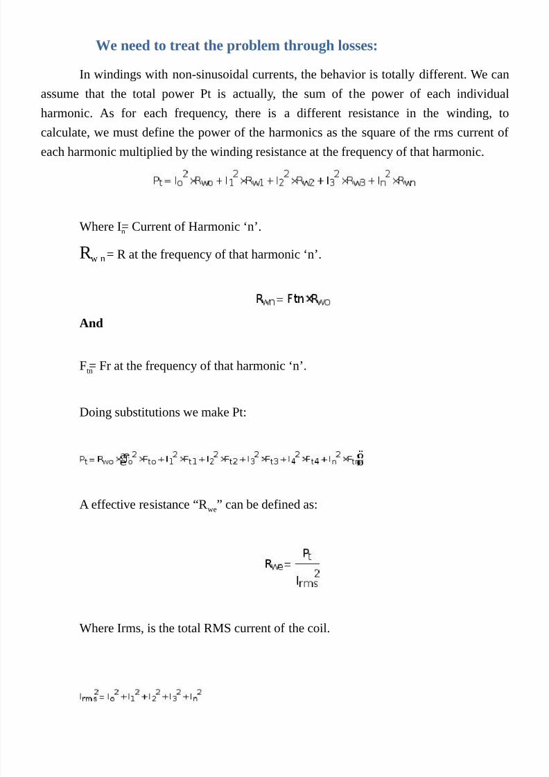
7/25/2019 Transformer's Book a Travel Over Different Aspects of Transformers, Inductors and Transductors - Humberto de So…
http://slidepdf.com/reader/full/transformers-book-a-travel-over-different-aspects-of-transformers-inductors 153/304
We need to treat the problem through losses:
In windings with non-sinusoidal currents, the behavior is totally different. We can
assume that the total power Pt is actually, the sum of the power of each individual
harmonic. As for each frequency, there is a different resistance in the winding, to
calculate, we must define the power of the harmonics as the square of the rms current ofeach harmonic multiplied by the winding resistance at the frequency of that harmonic.
Where In = Current of Harmonic ‘n’.
R w n = R at the frequency of that harmonic ‘n’.
And
Ftn = Fr at the frequency of that harmonic ‘n’.
Doing substitutions we make Pt:
A effective resistance “Rwe” can be defined as:
Where Irms, is the total RMS current of the coil.

7/25/2019 Transformer's Book a Travel Over Different Aspects of Transformers, Inductors and Transductors - Humberto de So…
http://slidepdf.com/reader/full/transformers-book-a-travel-over-different-aspects-of-transformers-inductors 154/304
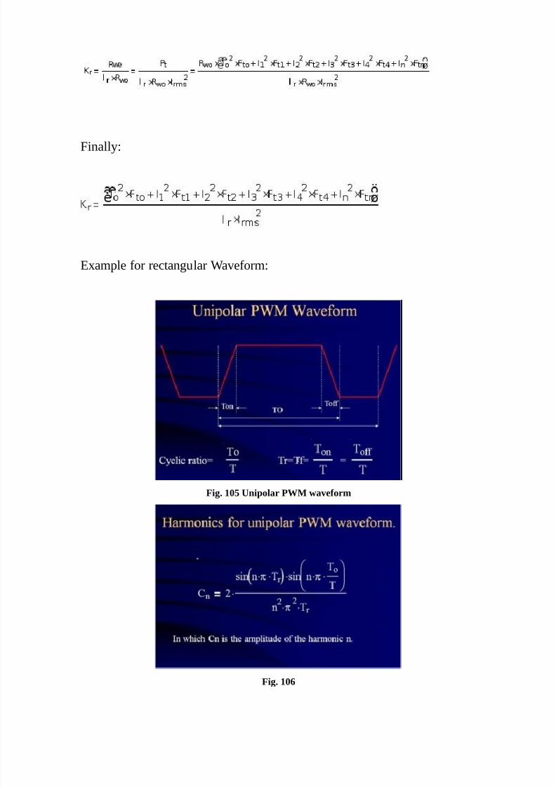
7/25/2019 Transformer's Book a Travel Over Different Aspects of Transformers, Inductors and Transductors - Humberto de So…
http://slidepdf.com/reader/full/transformers-book-a-travel-over-different-aspects-of-transformers-inductors 155/304
Finally:
Example for rectangular Waveform:
Fig. 105 Unipolar PWM waveform
Fig. 106
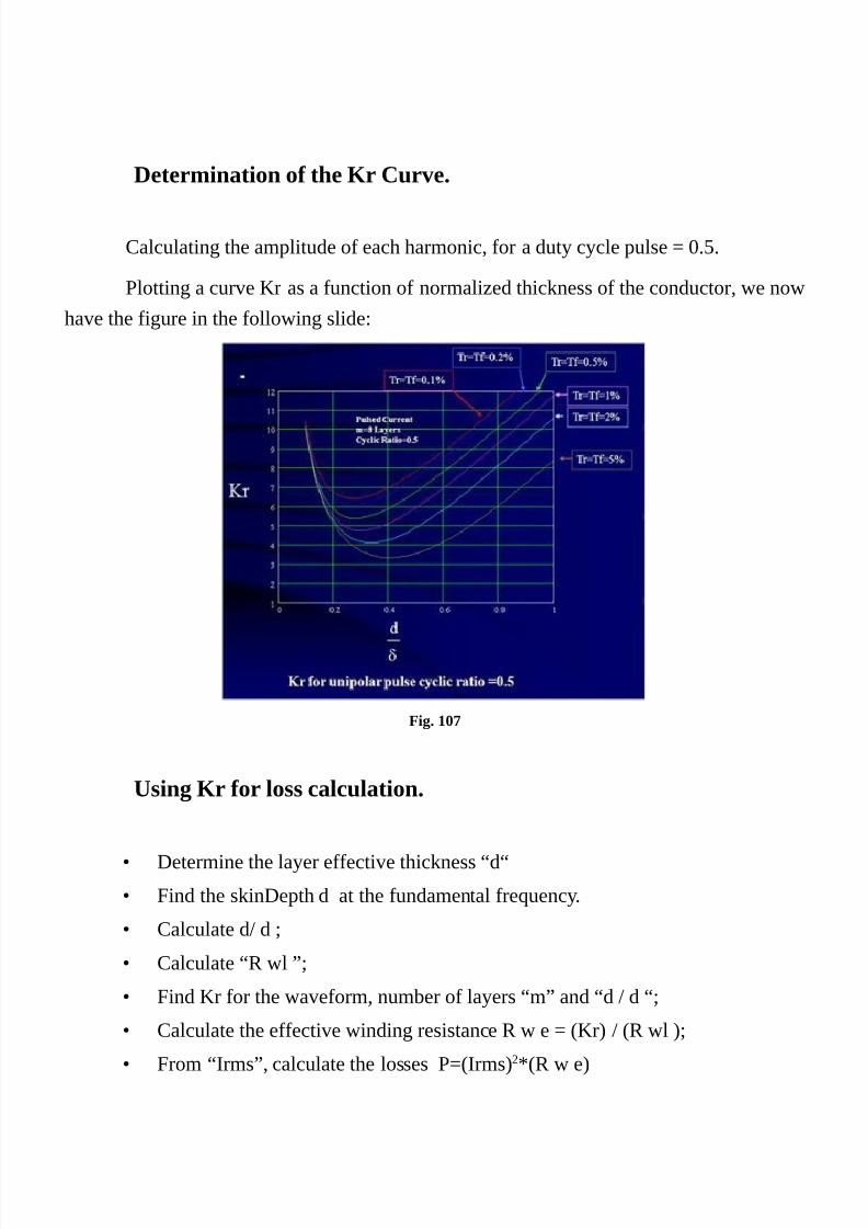
7/25/2019 Transformer's Book a Travel Over Different Aspects of Transformers, Inductors and Transductors - Humberto de So…
http://slidepdf.com/reader/full/transformers-book-a-travel-over-different-aspects-of-transformers-inductors 156/304
Determination of the Kr Curve.
Calculating the amplitude of each harmonic, for a duty cycle pulse = 0.5.
Plotting a curve Kr as a function of normalized thickness of the conductor, we now
have the figure in the following slide:
Fig. 107
Using Kr for loss calculation.
•
Determine the layer effective thickness “d“
•
Find the skinDepth d at the fundamental frequency.
•
Calculate d/ d ;
• Calculate “R wl ”;
• Find Kr for the waveform, number of layers “m” and “d / d “;
• Calculate the effective winding resistance R w e = (Kr) / (R wl );
• From “Irms”, calculate the losses P=(Irms)2*(R w e)

7/25/2019 Transformer's Book a Travel Over Different Aspects of Transformers, Inductors and Transductors - Humberto de So…
http://slidepdf.com/reader/full/transformers-book-a-travel-over-different-aspects-of-transformers-inductors 157/304
Fig. 108
Fig. 109

7/25/2019 Transformer's Book a Travel Over Different Aspects of Transformers, Inductors and Transductors - Humberto de So…
http://slidepdf.com/reader/full/transformers-book-a-travel-over-different-aspects-of-transformers-inductors 158/304
Further simplification with harmonics
We can further simplify these studies by applying the truncation of the results of
the series of Mr and Dr functions and final function of Fr. In our previous study for the
simplification of calculation of Fr, we had:
Where:
We can expand the current waveform in Fourier series:
The Sin and Cos terms can be combined In an alternative way:
As the losses being:
We can do:
If:

7/25/2019 Transformer's Book a Travel Over Different Aspects of Transformers, Inductors and Transductors - Humberto de So…
http://slidepdf.com/reader/full/transformers-book-a-travel-over-different-aspects-of-transformers-inductors 159/304
Then:
As:
Making d defined for the fundamental and λr for each harmonic, we have:
Replacing:
We can easily identify the first 2 terms as the RMS Current:

7/25/2019 Transformer's Book a Travel Over Different Aspects of Transformers, Inductors and Transductors - Humberto de So…
http://slidepdf.com/reader/full/transformers-book-a-travel-over-different-aspects-of-transformers-inductors 160/304

7/25/2019 Transformer's Book a Travel Over Different Aspects of Transformers, Inductors and Transductors - Humberto de So…
http://slidepdf.com/reader/full/transformers-book-a-travel-over-different-aspects-of-transformers-inductors 161/304
Where:
First Example: Calculation of a 4 Layers transformer with Copper
sheet in the two coils.
Let’s calculate the AC resistance of a coil with 4 layers of copper sheet
the sheet of copper has thickness 0.1 mm and width 26mm
The total length is 300mm.
The frequency is 100Khz.
The waveform is monopolar with Cyclic ratio of 0.50 and Tf=Tr=0.05T
First the calculation of the RMS of the current:
To calculate the RMS value and the RMS value of the derivative of the waveform, we can
make the frequency=1Hz, thus normalizing the values and keeping w=2*pi.
Then:
Calculating the RMS Current of the Derivative:
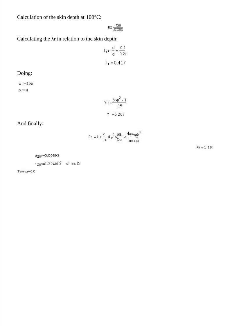
7/25/2019 Transformer's Book a Travel Over Different Aspects of Transformers, Inductors and Transductors - Humberto de So…
http://slidepdf.com/reader/full/transformers-book-a-travel-over-different-aspects-of-transformers-inductors 162/304
Calculation of the skin depth at 100°C:
Calculating the λr in relation to the skin depth:
Doing:
And finally:

7/25/2019 Transformer's Book a Travel Over Different Aspects of Transformers, Inductors and Transductors - Humberto de So…
http://slidepdf.com/reader/full/transformers-book-a-travel-over-different-aspects-of-transformers-inductors 163/304
Conductor cross sectional surface calculation:
Resistance of the conductor in ohms:
AC resistance of the conductor:

7/25/2019 Transformer's Book a Travel Over Different Aspects of Transformers, Inductors and Transductors - Humberto de So…
http://slidepdf.com/reader/full/transformers-book-a-travel-over-different-aspects-of-transformers-inductors 164/304
Second example: Calculating ht losses:
What would be the value of the losses if the peak current were100A.
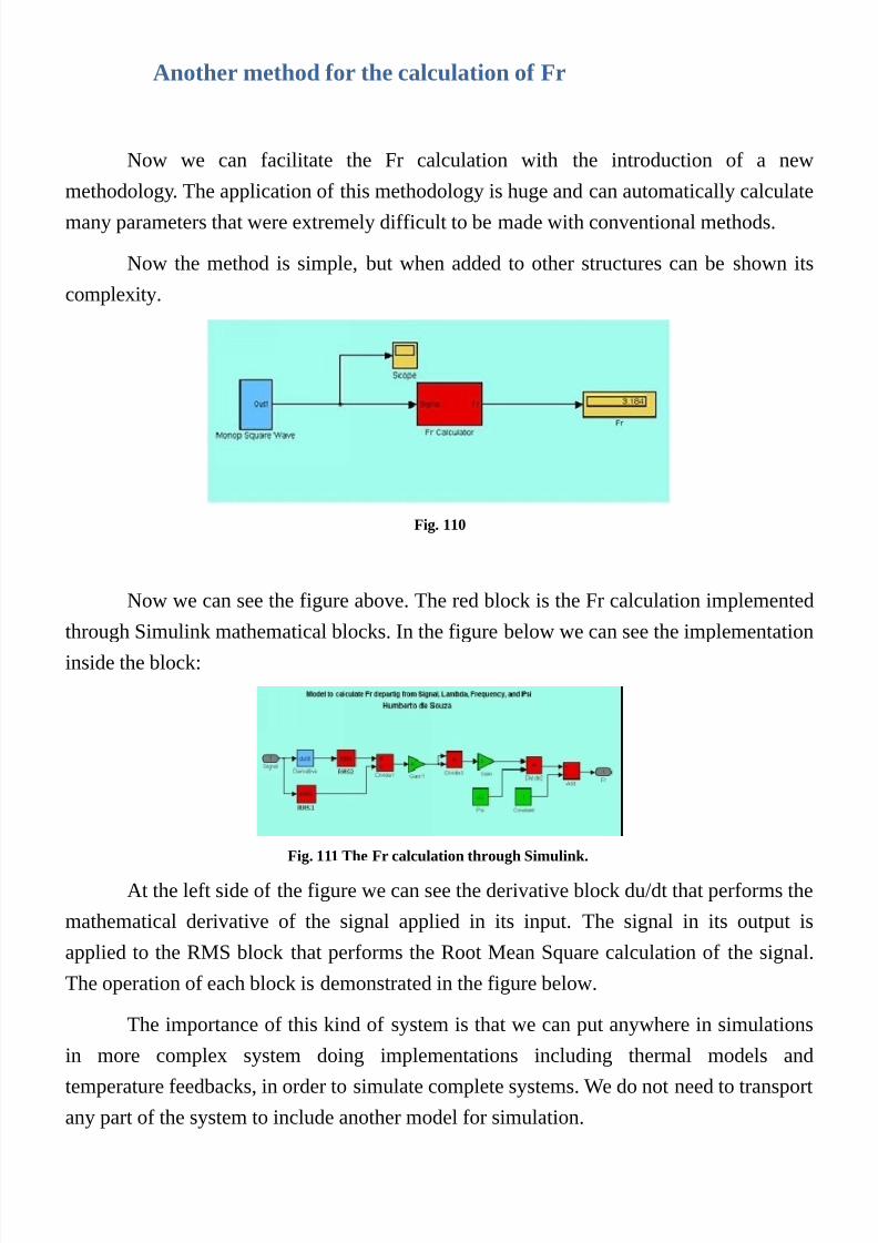
7/25/2019 Transformer's Book a Travel Over Different Aspects of Transformers, Inductors and Transductors - Humberto de So…
http://slidepdf.com/reader/full/transformers-book-a-travel-over-different-aspects-of-transformers-inductors 165/304
Another method for the calculation of Fr
Now we can facilitate the Fr calculation with the introduction of a new
methodology. The application of this methodology is huge and can automatically calculate
many parameters that were extremely difficult to be made with conventional methods.
Now the method is simple, but when added to other structures can be shown its
complexity.
Fig. 110
Now we can see the figure above. The red block is the Fr calculation implemented
through Simulink mathematical blocks. In the figure below we can see the implementationinside the block:
Fig. 111 The Fr calculation through Simulink.
At the left side of the figure we can see the derivative block du/dt that performs the
mathematical derivative of the signal applied in its input. The signal in its output is
applied to the RMS block that performs the Root Mean Square calculation of the signal.
The operation of each block is demonstrated in the figure below.
The importance of this kind of system is that we can put anywhere in simulations
in more complex system doing implementations including thermal models andtemperature feedbacks, in order to simulate complete systems. We do not need to transport
any part of the system to include another model for simulation.

7/25/2019 Transformer's Book a Travel Over Different Aspects of Transformers, Inductors and Transductors - Humberto de So…
http://slidepdf.com/reader/full/transformers-book-a-travel-over-different-aspects-of-transformers-inductors 166/304
We have used such models even in the project of inductors, large power
transformers for UPS, railway rectifier, and many other power electronics equipments.
Fig. 112 In the blocks can be seen the calculation performed individually by the blocks and their results
Let us use it in the same problem we have calculated in the last example. First of
all we need to make an oscillator with the same specifications of the model used in the
calculations we have made.
Fig. 113 Filling in the mask with the requested values
In the oscillator we are adjusting the signal amplitude, the frequency the rise and
fall time as a percentage of the total period, and the cyclic ratio.
Fig. 114 The oscillator waveform
We got this:

7/25/2019 Transformer's Book a Travel Over Different Aspects of Transformers, Inductors and Transductors - Humberto de So…
http://slidepdf.com/reader/full/transformers-book-a-travel-over-different-aspects-of-transformers-inductors 167/304
We are setting up the values for 100A the signal amplitude, 100 Khz, rise time of
5% and cyclic ratio for 0.4.
Now we will setup our Fr calculator:
Fig. 115 Filling in the values for the calculator
Below we can see a partial view of the working of some parts:
Fig. 116 The waveform of the function and the waveform of the derivative of the function
In less than 10 seconds we have our result:

7/25/2019 Transformer's Book a Travel Over Different Aspects of Transformers, Inductors and Transductors - Humberto de So…
http://slidepdf.com/reader/full/transformers-book-a-travel-over-different-aspects-of-transformers-inductors 168/304
Fig. 117
In the system diagram of fig. 117, can be included other variables, constants and
functions, in order to calculate more a complete task, like in fig. 118 were the system is
calculating the power loss, departing from the included resistance of the sheet, and like in
fig 119, departing from the geometry of the sheet and resistivity of the material.
Fig. 118

7/25/2019 Transformer's Book a Travel Over Different Aspects of Transformers, Inductors and Transductors - Humberto de So…
http://slidepdf.com/reader/full/transformers-book-a-travel-over-different-aspects-of-transformers-inductors 169/304
Fig. 119
The fig above can be used in calculation including the resistance of the coil. Its
bullshit but it serves to demonstrate potentiality. Mainly if combining many other different
aspects of circuitry.
Can be seen that the calculation are exactly the same like the values numericallycalculated step by step
Let’s talk some words about optimization:
In each solution there is a layer thickness that the resistance is the minimum value.
We now will concentrate in the solution to reach this mathematically.
First of all we need to normalize the equations in order to obtain values totally
dimensionless to allow us perform variations to investigate the behavior of the model.
The value of d is calculated as a function of the first harmonicfrequency,
temperature, resistivity, permeability and material, defining with that a reference value for
the DC resistance R d as a value referenced for the first harmonic skin depth d o.
As:

7/25/2019 Transformer's Book a Travel Over Different Aspects of Transformers, Inductors and Transductors - Humberto de So…
http://slidepdf.com/reader/full/transformers-book-a-travel-over-different-aspects-of-transformers-inductors 170/304
Doing substitutions:
Let’s plot a 3D graph as a function of D and the number of layers p for a certain
waveform (That one used in our last example):
Fig. 120A surface where the minimum values (Optimal width) is the valley of the plane plotted.
As we can see above, in each solution there is a layer thickness that the resistanceis the minimum value. We now will concentrate in the solution to reach this
mathematically.
First of all we need to normalize the equations in order to obtain values totally
dimensionless to allow us perform variations to investigate the behavior of the model.
Getting the derivative and setting it to zero:
Isolating D , we have:
Simplifying,we get the value of D for the minimum value of the Reff resistance:

7/25/2019 Transformer's Book a Travel Over Different Aspects of Transformers, Inductors and Transductors - Humberto de So…
http://slidepdf.com/reader/full/transformers-book-a-travel-over-different-aspects-of-transformers-inductors 171/304
Combining with:
We get the solution, for any arbitrary waveform, but for the optimal condition:
And finally we can get the final value for a specific D :
Now to normalize the entire system, we must arrange the formula to allow us see
the proper format to ensure simplicity of the calculation:
We can see the first term from left to right as being dependent of y , and the second
one dependent of the waveform and frequency. In reality this second term is dependent
solely of the waveform, being the angular frequency that appears in the formula coming
from the differentiation. Thus we can put the term dependent of the waveform in a table
of values or even in formulas for the calculation of their values. For the sake of simplicity,
if wanted, we can design a calculator of the second term in Matlab, Mathcad,
Mathematica, Saber or even a program in a convenient language that could allow us
calculate it easily.
Let’s design one with Simulink of the Matlab. Part of it is already ready in the
model we designed for the calculation of Fr. Our present design is simply a derivation of
that.

7/25/2019 Transformer's Book a Travel Over Different Aspects of Transformers, Inductors and Transductors - Humberto de So…
http://slidepdf.com/reader/full/transformers-book-a-travel-over-different-aspects-of-transformers-inductors 172/304
Fig. 121
Now we will calculate the optimum width of the foil from that calculation we have
done above.
Firstly we can determine the values from our oscillator:
Fig. 122

7/25/2019 Transformer's Book a Travel Over Different Aspects of Transformers, Inductors and Transductors - Humberto de So…
http://slidepdf.com/reader/full/transformers-book-a-travel-over-different-aspects-of-transformers-inductors 173/304
Solution other than for paper and pencil:
Today, the intense use of CAE systems do not require us spend our time
simplifying formulations of mathematical calculations.
In the past due to the use of the calculation rulers and even manual calculators, the
simplification of mathematical formulas, used to be very important. Today with the use of
computerized tools such as CAE Systems (MathCad, Math, Maple, Matlab, etc.) or even
programming in medium or high-level language such as Fortran, C, PLM, Basic, greatly
facilitate our work.
Over the past 20 years, we have employed more widely the combination of
symbolic and numerical methods for automatically solving complex mathematical
systems.
In our work of Power electronics with the time, we developed some topological
Matrix systems that we enter the incidences in hybrid matrices solving a lot of problems,
but practically not involving any complex intelligence we are doing about. The complex
intelligence was spent in the development of that tool developed in Maple.
Now we are presenting the simplified version of an old process for calculation of
powder core like m Kool of Magnetics for our high frequency inductors.
Calculation in the design of a 20Kva inverter filter inductor

7/25/2019 Transformer's Book a Travel Over Different Aspects of Transformers, Inductors and Transductors - Humberto de So…
http://slidepdf.com/reader/full/transformers-book-a-travel-over-different-aspects-of-transformers-inductors 174/304

7/25/2019 Transformer's Book a Travel Over Different Aspects of Transformers, Inductors and Transductors - Humberto de So…
http://slidepdf.com/reader/full/transformers-book-a-travel-over-different-aspects-of-transformers-inductors 175/304

7/25/2019 Transformer's Book a Travel Over Different Aspects of Transformers, Inductors and Transductors - Humberto de So…
http://slidepdf.com/reader/full/transformers-book-a-travel-over-different-aspects-of-transformers-inductors 176/304
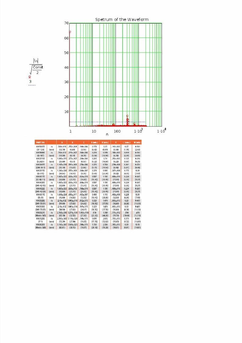
7/25/2019 Transformer's Book a Travel Over Different Aspects of Transformers, Inductors and Transductors - Humberto de So…
http://slidepdf.com/reader/full/transformers-book-a-travel-over-different-aspects-of-transformers-inductors 177/304

7/25/2019 Transformer's Book a Travel Over Different Aspects of Transformers, Inductors and Transductors - Humberto de So…
http://slidepdf.com/reader/full/transformers-book-a-travel-over-different-aspects-of-transformers-inductors 178/304

7/25/2019 Transformer's Book a Travel Over Different Aspects of Transformers, Inductors and Transductors - Humberto de So…
http://slidepdf.com/reader/full/transformers-book-a-travel-over-different-aspects-of-transformers-inductors 179/304

7/25/2019 Transformer's Book a Travel Over Different Aspects of Transformers, Inductors and Transductors - Humberto de So…
http://slidepdf.com/reader/full/transformers-book-a-travel-over-different-aspects-of-transformers-inductors 180/304
We can calculate the RMS of derivative of the current waveform used in the
example above and calculate the optimum exactly like the example of chapter xx in the
calculation of the K factor transformer.

7/25/2019 Transformer's Book a Travel Over Different Aspects of Transformers, Inductors and Transductors - Humberto de So…
http://slidepdf.com/reader/full/transformers-book-a-travel-over-different-aspects-of-transformers-inductors 181/304
Design of a ferrite 3Kva 200Khz power transformer for a ZVS-
QRC telecommunication SMPS.
One another example is the project of a power transformer for a ZVS Quasi
Resonant Converter – 52.8 Vdc/50A 200Khz SMPS:
This project was done in 1993 for a modular telecommunications power supply. in two
versions: one module of 50A/52.8Vdc and another of 100A/52.8Vdc. The photo of the
equipment can be seen in the end of this design procedure.

7/25/2019 Transformer's Book a Travel Over Different Aspects of Transformers, Inductors and Transductors - Humberto de So…
http://slidepdf.com/reader/full/transformers-book-a-travel-over-different-aspects-of-transformers-inductors 182/304

7/25/2019 Transformer's Book a Travel Over Different Aspects of Transformers, Inductors and Transductors - Humberto de So…
http://slidepdf.com/reader/full/transformers-book-a-travel-over-different-aspects-of-transformers-inductors 183/304
Fig. 123

7/25/2019 Transformer's Book a Travel Over Different Aspects of Transformers, Inductors and Transductors - Humberto de So…
http://slidepdf.com/reader/full/transformers-book-a-travel-over-different-aspects-of-transformers-inductors 184/304
For Secondary:

7/25/2019 Transformer's Book a Travel Over Different Aspects of Transformers, Inductors and Transductors - Humberto de So…
http://slidepdf.com/reader/full/transformers-book-a-travel-over-different-aspects-of-transformers-inductors 185/304
Fig. 124

7/25/2019 Transformer's Book a Travel Over Different Aspects of Transformers, Inductors and Transductors - Humberto de So…
http://slidepdf.com/reader/full/transformers-book-a-travel-over-different-aspects-of-transformers-inductors 186/304

7/25/2019 Transformer's Book a Travel Over Different Aspects of Transformers, Inductors and Transductors - Humberto de So…
http://slidepdf.com/reader/full/transformers-book-a-travel-over-different-aspects-of-transformers-inductors 187/304

7/25/2019 Transformer's Book a Travel Over Different Aspects of Transformers, Inductors and Transductors - Humberto de So…
http://slidepdf.com/reader/full/transformers-book-a-travel-over-different-aspects-of-transformers-inductors 188/304
PrimaryFor the Primary:

7/25/2019 Transformer's Book a Travel Over Different Aspects of Transformers, Inductors and Transductors - Humberto de So…
http://slidepdf.com/reader/full/transformers-book-a-travel-over-different-aspects-of-transformers-inductors 189/304

7/25/2019 Transformer's Book a Travel Over Different Aspects of Transformers, Inductors and Transductors - Humberto de So…
http://slidepdf.com/reader/full/transformers-book-a-travel-over-different-aspects-of-transformers-inductors 190/304

7/25/2019 Transformer's Book a Travel Over Different Aspects of Transformers, Inductors and Transductors - Humberto de So…
http://slidepdf.com/reader/full/transformers-book-a-travel-over-different-aspects-of-transformers-inductors 191/304

7/25/2019 Transformer's Book a Travel Over Different Aspects of Transformers, Inductors and Transductors - Humberto de So…
http://slidepdf.com/reader/full/transformers-book-a-travel-over-different-aspects-of-transformers-inductors 192/304

7/25/2019 Transformer's Book a Travel Over Different Aspects of Transformers, Inductors and Transductors - Humberto de So…
http://slidepdf.com/reader/full/transformers-book-a-travel-over-different-aspects-of-transformers-inductors 193/304

7/25/2019 Transformer's Book a Travel Over Different Aspects of Transformers, Inductors and Transductors - Humberto de So…
http://slidepdf.com/reader/full/transformers-book-a-travel-over-different-aspects-of-transformers-inductors 194/304
Fig. 125
Fig. 126

7/25/2019 Transformer's Book a Travel Over Different Aspects of Transformers, Inductors and Transductors - Humberto de So…
http://slidepdf.com/reader/full/transformers-book-a-travel-over-different-aspects-of-transformers-inductors 195/304

7/25/2019 Transformer's Book a Travel Over Different Aspects of Transformers, Inductors and Transductors - Humberto de So…
http://slidepdf.com/reader/full/transformers-book-a-travel-over-different-aspects-of-transformers-inductors 196/304
The Gap Losses - The approach

7/25/2019 Transformer's Book a Travel Over Different Aspects of Transformers, Inductors and Transductors - Humberto de So…
http://slidepdf.com/reader/full/transformers-book-a-travel-over-different-aspects-of-transformers-inductors 197/304
The visual effect of the gaps
Let´s consider a core with three gaps with a certain frequency:
Fig. 128
Vortex of induced currents in a cylindrical conductor due to dispersed fields.
Fig. 129
Loss on a cylindrical conductor subjected to a field perpendicular to its axis
For cylindrical conductors of small diameter d compared with d, the loss by eddy
current (proximity effect) due to an ac field amplitude B, perpendicular to the axis of
conductor and w frequency is:
Where d is the diameter l is the conductor length and r c is the resistivity
For the complete winding the total loss is:

7/25/2019 Transformer's Book a Travel Over Different Aspects of Transformers, Inductors and Transductors - Humberto de So…
http://slidepdf.com/reader/full/transformers-book-a-travel-over-different-aspects-of-transformers-inductors 198/304
Where lt is the length of one turn, Au is the portion of the window area that is
really being used. is the spatial mean square of the magnetic field in that region and
Fp is the packing factor with N being the number of turns and n the number
of conductors per turn. From the equation we can conclude that the loss by proximity
effect is proportional to area times the square of the field in that area.

7/25/2019 Transformer's Book a Travel Over Different Aspects of Transformers, Inductors and Transductors - Humberto de So…
http://slidepdf.com/reader/full/transformers-book-a-travel-over-different-aspects-of-transformers-inductors 199/304
Determination of losses by finite elements:
When we make the magnetic measurement in 2D window using FEMM, we are
getting the energy in Joules / m.
We know that the energy stored in the magnetic field is:
At present, we need the B square average over the area:
How the energy is proportional to the sum of B2:
We can simply multiply the energy by 2 and mo and we have the product, and in
this way, replace it in the equation of loss of the conductor.
Making , We have:

7/25/2019 Transformer's Book a Travel Over Different Aspects of Transformers, Inductors and Transductors - Humberto de So…
http://slidepdf.com/reader/full/transformers-book-a-travel-over-different-aspects-of-transformers-inductors 200/304
\
Although the differential equations that describe the phenomena are relatively
compact,
It is very difficult to get closed solutions, except for extremely simple geometries.Here is where the idea of the finite element, which breaks the complex geometry in a large
number of simple design elements.
The advantage of breaking the complex geometry in a large number of simple
elements, is that we turn a small problem but difficult to solve in a big problem, but of
relatively simple solution. Specifically, triangulation serves this purpose, as it reduces the
case to a simple solution of linear algebra, with perhaps tens of thousands of unknowns.
The FEMM uses triangular elements. About each element, the solution is
approximated by linear interpolation of the values in the three vertices of the triangle. The
linear algebra problem is formed by the choice of solution based on minimizing the total
energy.
The calculation of losses in Litz Wires
We designed two cores DIN E30 of a 48V/10A power supply resonant inductor.
We designed them in Solidworks, in two versions, one with a central gap, and another
with gap on all legs and through DXF we transferred it for FEMM, setting the ferrite core
with parameters (magnetic curve, resistivity, etc.) and created a copper block with a
current density to establish a similar field H created by the actual reel. The test is
magnetostatic 2D (two-dimensional) and the triangulation was made in order to provide us
with a precision compatible with our current and simple goals to avoid lengthy
calculations.
The energy was measured in FEMM in one of the copper blocks (in green in the
figure above) and we 1.0642 * 10-2 Joules per meter, then:
Number of conductors in the Litz Wire:
Number of turns:

7/25/2019 Transformer's Book a Travel Over Different Aspects of Transformers, Inductors and Transductors - Humberto de So…
http://slidepdf.com/reader/full/transformers-book-a-travel-over-different-aspects-of-transformers-inductors 201/304
Area Utilized:
Mean turn:
Angular frequency:
Packing Factor:
Copper resistivity:
The conclusion is that the loss in copper for the 130 conductors #42 litz wire is:
We will vary the wire gauge keeping the total area of the conductor. All the
anterior values will be valid for the present calculation:
As:
Arranging:
Ranging the gauge (AWG) from #30 Up to #50:

7/25/2019 Transformer's Book a Travel Over Different Aspects of Transformers, Inductors and Transductors - Humberto de So…
http://slidepdf.com/reader/full/transformers-book-a-travel-over-different-aspects-of-transformers-inductors 202/304
Packing Factor:
Plotting:

7/25/2019 Transformer's Book a Travel Over Different Aspects of Transformers, Inductors and Transductors - Humberto de So…
http://slidepdf.com/reader/full/transformers-book-a-travel-over-different-aspects-of-transformers-inductors 203/304
Conductor Diameter:
Like defined in the American Wire and Gauge the diameter of the wire in
accordance with the AWG number in inches is:
To get in millimeters multiply by 25.4:
To get in meters, like our present need:
Some other considerations were made, but the most interesting is to prevent theoccupation of area where the borders (most intense fields) are more frequent. With this
objective in mind we will have a staggered winding wire of litz wire conductors 130 # 42
more or less as follows:

7/25/2019 Transformer's Book a Travel Over Different Aspects of Transformers, Inductors and Transductors - Humberto de So…
http://slidepdf.com/reader/full/transformers-book-a-travel-over-different-aspects-of-transformers-inductors 204/304
Fig. 132 -
Another approach of inductors is the confrontation of the high reluctance regions
nearby the gaps. This effect combined with the skin effect produces a result where the
winding configuration with respect to the gap position is very important. In the following
figures we can observe the high current regions with curled plates.The following sequence of figures will give us an idea of this effect.
Fig. 133 DEisperse field at the frequency of 60Hz
Fig. 134 Frequeny at 120Hz
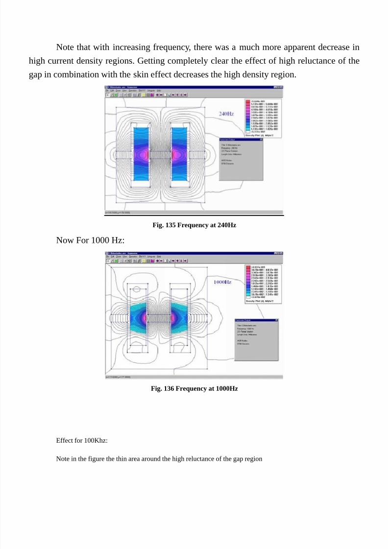
7/25/2019 Transformer's Book a Travel Over Different Aspects of Transformers, Inductors and Transductors - Humberto de So…
http://slidepdf.com/reader/full/transformers-book-a-travel-over-different-aspects-of-transformers-inductors 205/304
Note that with increasing frequency, there was a much more apparent decrease in
high current density regions. Getting completely clear the effect of high reluctance of the
gap in combination with the skin effect decreases the high density region.
Fig. 135 Frequency at 240Hz
Now For 1000 Hz:
Fig. 136 Frequency at 1000Hz
Effect for 100Khz:
Note in the figure the thin area around the high reluctance of the gap region

7/25/2019 Transformer's Book a Travel Over Different Aspects of Transformers, Inductors and Transductors - Humberto de So…
http://slidepdf.com/reader/full/transformers-book-a-travel-over-different-aspects-of-transformers-inductors 206/304
Fig. 137 Frequency at 100.000 Hz
Changing the position of the winding:
Returning to 10,000Hz and shifting the position of the winding, we can see the
highest density film forming toward high reluctance region. Likewise, it can be noted the
effect of a spreading reluctance. This is due to the reluctance behavior, spreading the
extent to which departs. Behaving in different ways exactly like a light source
Fig. 138

7/25/2019 Transformer's Book a Travel Over Different Aspects of Transformers, Inductors and Transductors - Humberto de So…
http://slidepdf.com/reader/full/transformers-book-a-travel-over-different-aspects-of-transformers-inductors 207/304
Fig. 139
Fig. 140
Now at 1000 Hz:
Fig. 141
At 10000 Hz.
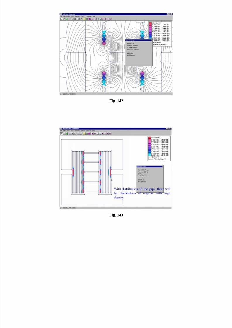
7/25/2019 Transformer's Book a Travel Over Different Aspects of Transformers, Inductors and Transductors - Humberto de So…
http://slidepdf.com/reader/full/transformers-book-a-travel-over-different-aspects-of-transformers-inductors 208/304
Fig. 142
Fig. 143
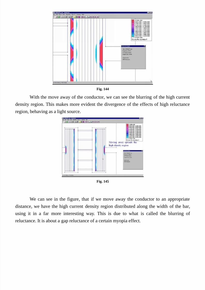
7/25/2019 Transformer's Book a Travel Over Different Aspects of Transformers, Inductors and Transductors - Humberto de So…
http://slidepdf.com/reader/full/transformers-book-a-travel-over-different-aspects-of-transformers-inductors 209/304
Fig. 144
With the move away of the conductor, we can see the blurring of the high currentdensity region. This makes more evident the divergence of the effects of high reluctance
region, behaving as a light source.
Fig. 145
We can see in the figure, that if we move away the conductor to an appropriate
distance, we have the high current density region distributed along the width of the bar,
using it in a far more interesting way. This is due to what is called the blurring of
reluctance. It is about a gap reluctance of a certain myopia effect.
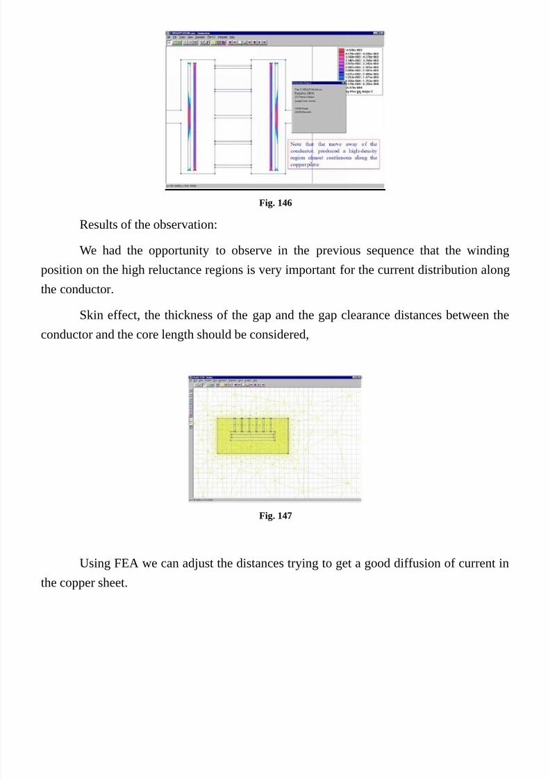
7/25/2019 Transformer's Book a Travel Over Different Aspects of Transformers, Inductors and Transductors - Humberto de So…
http://slidepdf.com/reader/full/transformers-book-a-travel-over-different-aspects-of-transformers-inductors 210/304
Fig. 146
Results of the observation:
We had the opportunity to observe in the previous sequence that the winding
position on the high reluctance regions is very important for the current distribution along
the conductor.
Skin effect, the thickness of the gap and the gap clearance distances between the
conductor and the core length should be considered,
Fig. 147
Using FEA we can adjust the distances trying to get a good diffusion of current in
the copper sheet.

7/25/2019 Transformer's Book a Travel Over Different Aspects of Transformers, Inductors and Transductors - Humberto de So…
http://slidepdf.com/reader/full/transformers-book-a-travel-over-different-aspects-of-transformers-inductors 211/304
Fig. 148
This model has been created in FEMM, departing from the normalization of
dimensions as a function of the skin depth of the frequency under test.
Sullivan and Jinkun [10] investigated this phenomenon and through simulation
plus curve fitting, they determined a relationship that with a good precision for practicalpurposes, describes its behavior.
They used five basic dimensions as can be seen from the figure.
It can be seen that with the movement away, there was a greater distribution of the
surface, thereby increasing the higher density regions reducing the overall resistance of the
winding.
Fig. 149
The framework was reduced through a simplification of the structure of theproblem, doing a infinite number of gaps distributed in an infinite length sheet. Thus the
problem can be analyzed in one of those gaps, considering the boundaries of the core to
be infinite. With those assumptions the number of variables was reduced for 3, The gap
pitch p, the gap length g, and the spacing between the sheet and the gap. The thickness of
the core are not important, so as the distance between the copper sheet and the botton part
of the cores due obviously to the fact that being the reluctance of the core low, the
diffusion of the current in this region of the copper sheet tends to be zero. Unless there is apossible DC component.
The parameters that were changed during the simulation process were p, g and s

7/25/2019 Transformer's Book a Travel Over Different Aspects of Transformers, Inductors and Transductors - Humberto de So…
http://slidepdf.com/reader/full/transformers-book-a-travel-over-different-aspects-of-transformers-inductors 212/304
because the width of the copper sheet was maintained constant in two skin depth due to
the fact that thicker conductor could only contribute for the DC component.
Fig. 150
The g parameter was maintained constant also to keep the simulation easier, but
also because if we change p we are automatically changing g.The simulations results were plotted in curves giving resistance factors Fr, for
various values of p and s in a 3 D surface like shown in the figure xx.
Fig. 151
The curves plotted by finite elements simulations, were used to curve fitting and
the result was an analytical approximation formula that facilitates calculation due to the
without need to use tables or everything else to design quasi distributed inductors.
Where:

7/25/2019 Transformer's Book a Travel Over Different Aspects of Transformers, Inductors and Transductors - Humberto de So…
http://slidepdf.com/reader/full/transformers-book-a-travel-over-different-aspects-of-transformers-inductors 213/304
Like informed by Sullivan and Jinkun in [10] the expression approximation and the
simulation presented an error less than 4.5% and an absolute error in Fr less than 0.08.
And that the expression is maintained accurate even with large values of s and p.
For large s, k and b become:
And the expression is rewritten to:
If the ratio of is much greater than 3.33, the equation will enter a roughly linear
region and it can be simplified as:
By the other side, if the ratio of is much smaller than 3.33 the equation is enter
in a constant region with Fr=1.9.
We can get good results and get Fr near that one obtained in distributed inductors
(Fr = 2.5) if we maintain the following conditions:
P<2.5 ×d
If the gap length is high, it can also reduce the ac resistance. But it needs to be kept

7/25/2019 Transformer's Book a Travel Over Different Aspects of Transformers, Inductors and Transductors - Humberto de So…
http://slidepdf.com/reader/full/transformers-book-a-travel-over-different-aspects-of-transformers-inductors 214/304
substantially low when compared to the gap pitch.
Like initially presented to us, this problem is first of all a geometric puzzle and the
guidelines were presented. The solution for the rest of the problem is like the others.

7/25/2019 Transformer's Book a Travel Over Different Aspects of Transformers, Inductors and Transductors - Humberto de So…
http://slidepdf.com/reader/full/transformers-book-a-travel-over-different-aspects-of-transformers-inductors 215/304
The End Effect
Another kind of scattered field inside window is the “End Effect” that is the
responsible for the heat of the ends of coil in transformers. This will be studied in volume
2.
Fig. 152 There are perpendicular H lines in the coil
Fig. 153 The red line at the top is draw for the calculatio of the normal elements.
Fig. 154 The values of normal elements

7/25/2019 Transformer's Book a Travel Over Different Aspects of Transformers, Inductors and Transductors - Humberto de So…
http://slidepdf.com/reader/full/transformers-book-a-travel-over-different-aspects-of-transformers-inductors 216/304
The problem of the sizeThe size of a transformer is constrained by many factors: Temperature, power loss,
cost, size, Induction, voltage regulation, Impedance, Inductance, harmonics and others.
The determination of the dimensions of the transformer is a quite complex task,
because there are infinite possibilities of dimensions and also infinite relations between
them.

7/25/2019 Transformer's Book a Travel Over Different Aspects of Transformers, Inductors and Transductors - Humberto de So…
http://slidepdf.com/reader/full/transformers-book-a-travel-over-different-aspects-of-transformers-inductors 217/304

7/25/2019 Transformer's Book a Travel Over Different Aspects of Transformers, Inductors and Transductors - Humberto de So…
http://slidepdf.com/reader/full/transformers-book-a-travel-over-different-aspects-of-transformers-inductors 218/304

7/25/2019 Transformer's Book a Travel Over Different Aspects of Transformers, Inductors and Transductors - Humberto de So…
http://slidepdf.com/reader/full/transformers-book-a-travel-over-different-aspects-of-transformers-inductors 219/304
frequency and current density in copper.
There are also many different technologies and applications: High, medium and
low power transformers, High frequency, High frequency medium power, planar high
frequency, fly back, forward half pulse and further huge universe of possibilities, being
each one a particular scenario of vast possibilities.
Even in power transformers we have many possibilities in the design. Composite
laminates, cruciform cores, number of steps, 90 degree cutting, 45 degree cutting and so
forth,.
We will begin with the magnetic cross sectional area Aef. We have the working
frequency and the max flux density. Thus considering that our transformer have one turn,
there will be a voltage in it. If besides we imagine that our one turn winding is a block of
copper with same area of the entire coil of the primary (Or secondary). You must
hypothetically consider the individual cross sectional area of the copper multiplied by the
number of turns. This performs the total useful copper area.
Considering the figure nest page, there we have a transformer window full of
windings of copper wire.
The space (Area) occupied by the copper is naturally less than the total window.
Thus we have a occupation factor Kjan that is called “Space Factor” of the copper in the
window.

7/25/2019 Transformer's Book a Travel Over Different Aspects of Transformers, Inductors and Transductors - Humberto de So…
http://slidepdf.com/reader/full/transformers-book-a-travel-over-different-aspects-of-transformers-inductors 220/304
Fig. 156
First of all we will determine the formulation about the geometry of an EI
transformer then we will be calculating the temperature of a transformer in order at
the end determine the size and the main parameters.
Using our study, let us calculate a input transformer for a UPS of 80Kva.
We need to determine the lowest cost and the optimum relations for a and b, thus
determining the best conditions for a three phase transformer using right angle composite
lamination.
For the EI transformer we must first to consider the most common normalized
relation of EI lamination. There are other values that can be analyzed for each particular
case.
In the formulation we are treating them in normalized form giving space to
introduce the factors for other standards.

7/25/2019 Transformer's Book a Travel Over Different Aspects of Transformers, Inductors and Transductors - Humberto de So…
http://slidepdf.com/reader/full/transformers-book-a-travel-over-different-aspects-of-transformers-inductors 221/304
EI Core transformer:
Calculating over a single Phase EI lamination transformer
The Coil
Defining the core normalized dimensions

7/25/2019 Transformer's Book a Travel Over Different Aspects of Transformers, Inductors and Transductors - Humberto de So…
http://slidepdf.com/reader/full/transformers-book-a-travel-over-different-aspects-of-transformers-inductors 222/304
Length of the window:
Height of window Area:
Core Window Area:
Core Width:
Core Height:
Lamination Surface:
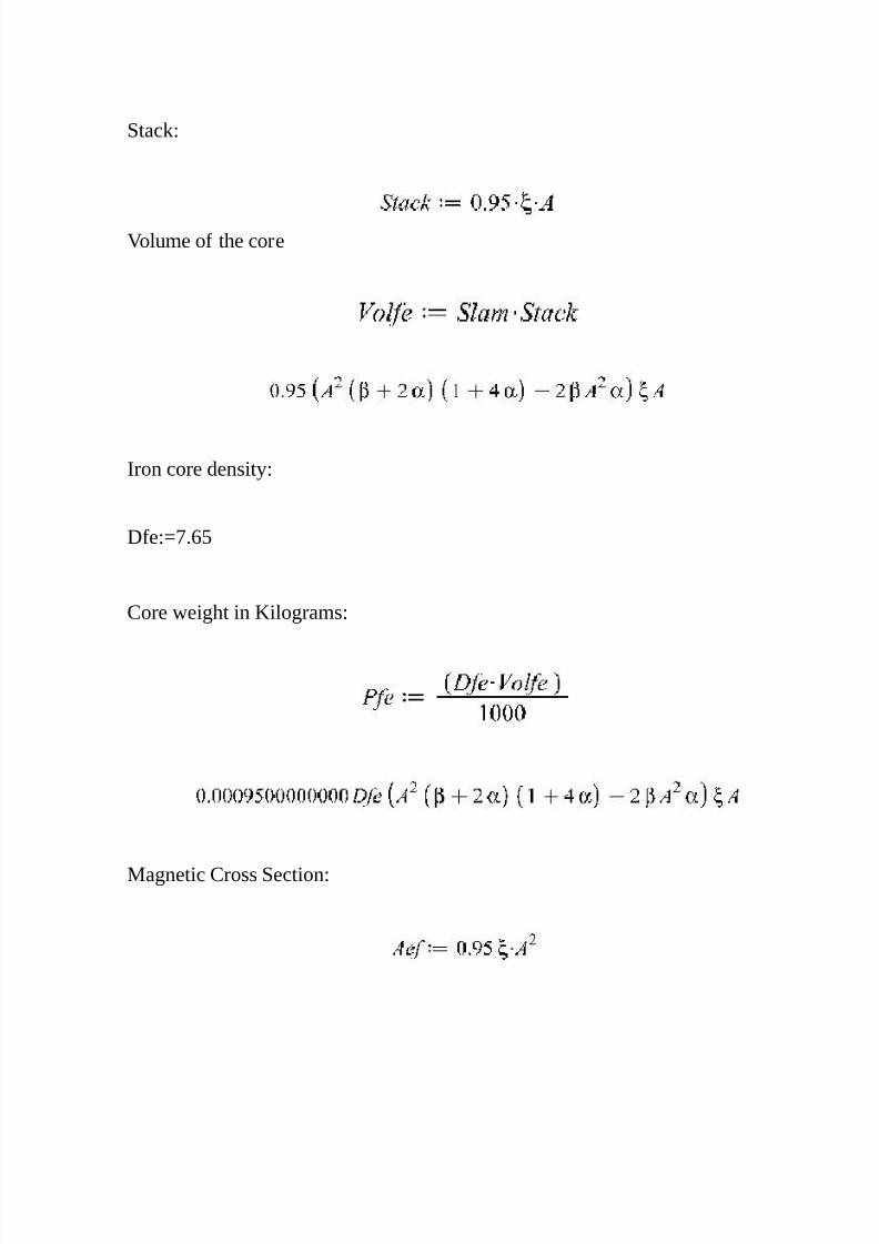
7/25/2019 Transformer's Book a Travel Over Different Aspects of Transformers, Inductors and Transductors - Humberto de So…
http://slidepdf.com/reader/full/transformers-book-a-travel-over-different-aspects-of-transformers-inductors 223/304
Stack:
Volume of the core
Iron core density:
Dfe:=7.65
Core weight in Kilograms:
Magnetic Cross Section:

7/25/2019 Transformer's Book a Travel Over Different Aspects of Transformers, Inductors and Transductors - Humberto de So…
http://slidepdf.com/reader/full/transformers-book-a-travel-over-different-aspects-of-transformers-inductors 224/304
Fig. 157
Mean turn length:
Volume of Copper (Primary and secondary together):
Density of Copper (Reference Value)
Weight of copper:
Current Density:
We are defining Di as current density in (Amper’s)/Cm2:
The current of coil is:
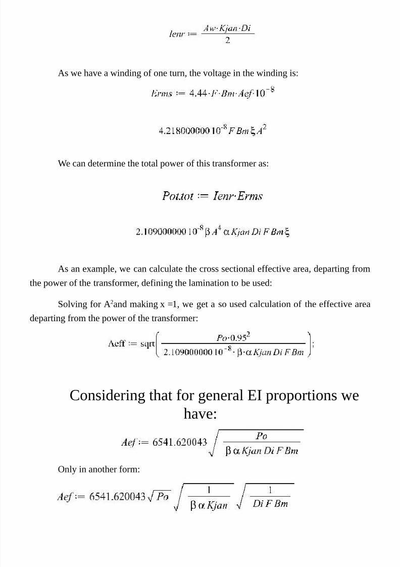
7/25/2019 Transformer's Book a Travel Over Different Aspects of Transformers, Inductors and Transductors - Humberto de So…
http://slidepdf.com/reader/full/transformers-book-a-travel-over-different-aspects-of-transformers-inductors 225/304
As we have a winding of one turn, the voltage in the winding is:
We can determine the total power of this transformer as:
As an example, we can calculate the cross sectional effective area, departing from
the power of the transformer, defining the lamination to be used:
Solving for A2and making x =1, we get a so used calculation of the effective area
departing from the power of the transformer:
Considering that for general EI proportions we
have:
Only in another form:
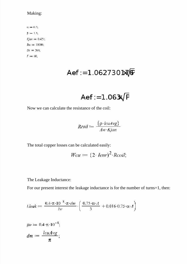
7/25/2019 Transformer's Book a Travel Over Different Aspects of Transformers, Inductors and Transductors - Humberto de So…
http://slidepdf.com/reader/full/transformers-book-a-travel-over-different-aspects-of-transformers-inductors 226/304
Making:
Now we can calculate the resistance of the coil:
The total copper losses can be calculated easily:
The Leakage Inductance:
For our present interest the leakage inductance is for the number of turns=1, then:

7/25/2019 Transformer's Book a Travel Over Different Aspects of Transformers, Inductors and Transductors - Humberto de So…
http://slidepdf.com/reader/full/transformers-book-a-travel-over-different-aspects-of-transformers-inductors 227/304
By normalized parameter, we find:
The reactive power in the leakage inductance in Vars is:
Iron Losses:
The iron losses, depends on the flux density and frequency of use:
For a given condition we get the information from the curves of the magnetic core,
the loss is in watts per kilogram:
DenspPferro (Loss density of the iron core).
Now we can get the losses in the iron:
The temperature calculation formula is derived from a general study for
temperature discussed in “Loss and weight approach” in “The problem of Temperature” in
the Second Volume of this book.
The average temperature is calculated from:
We can also determine the temperature from calculating the specific dissipation in
watts/cm2 in the area in blue, shown in the figure below.
The graph of next page can be used to determine the final temperature.

7/25/2019 Transformer's Book a Travel Over Different Aspects of Transformers, Inductors and Transductors - Humberto de So…
http://slidepdf.com/reader/full/transformers-book-a-travel-over-different-aspects-of-transformers-inductors 228/304
Fig. 158 The Dissipation areas of the transformer
They are the vertical areas used for heat dissipation.
Normally the areas that take part of the dissipation process are the vertical ones
that work in the air convection, which is the major part of the cooling process.
T0,T25 and T50 are graphs for ambient temperatures of 0, 25 and 50 ° C
respectively.
Making:

7/25/2019 Transformer's Book a Travel Over Different Aspects of Transformers, Inductors and Transductors - Humberto de So…
http://slidepdf.com/reader/full/transformers-book-a-travel-over-different-aspects-of-transformers-inductors 229/304
Deriving from t we can calculate de current density required for that temperature:
At last, we define the current density:
Now we will plot two graphs of Di as a function of the central lag width. One for A
Class (105 ° C) and the second one for B Class (130 ° C).
Curve for A class (105 ° C) transformers:
Fig. 159Current density calculation from central leg Class A (105 ° C)
The parameters of the curves are for 1Watt per Kilogram, 2Watts per Kilogram,
3Watts per Kilogram and 4 Watts per Kilogram . In the abscissa we have the central leg of

7/25/2019 Transformer's Book a Travel Over Different Aspects of Transformers, Inductors and Transductors - Humberto de So…
http://slidepdf.com/reader/full/transformers-book-a-travel-over-different-aspects-of-transformers-inductors 230/304
the “E” lamination and in the ordinate the current density.
Curve for B class (130 ° C) Transformers:
Fig. 160Current density calculation from central leg Class B (130 ° C)
Now we need to calculate the percentage of copper losses:
The percentage of reactive leakage power can be determined:
Voltage regulation of the transformer:

7/25/2019 Transformer's Book a Travel Over Different Aspects of Transformers, Inductors and Transductors - Humberto de So…
http://slidepdf.com/reader/full/transformers-book-a-travel-over-different-aspects-of-transformers-inductors 231/304

7/25/2019 Transformer's Book a Travel Over Different Aspects of Transformers, Inductors and Transductors - Humberto de So…
http://slidepdf.com/reader/full/transformers-book-a-travel-over-different-aspects-of-transformers-inductors 232/304
Design of a sample E I transformer:
Values for calculation:
Voltage of secondary:
Vsec=100V
Voltage of Primary:
Vprim=100V
Output current (Current of secondary):
Isec=5.90A
Flux density:
Bm=10000 Gausses.
Relations of lamination:
A =0.5
B =1.5
Kjan=0.421
x =1
We can select A=5:
For 10 Kilogausses the loss density for the silicon iron we are using is:
1 Watt/Kg

7/25/2019 Transformer's Book a Travel Over Different Aspects of Transformers, Inductors and Transductors - Humberto de So…
http://slidepdf.com/reader/full/transformers-book-a-travel-over-different-aspects-of-transformers-inductors 233/304
Fig. 161Current density calculation from central leg Class A (105 ° C)
Using the graph, as shown, we get:
Di=2.24A/mm2
By the current density, we can get the cross sectional area of the conductor:
By the AWG table we get: Scu=2.634 Diamcu=1.88 (With insulating Varnish).
We are now calculating the voltage regulation due to leakage inductance and
resistance of primary and secondary coils:
The approximate value is:
Calculation of the number of turns:
E=100V:

7/25/2019 Transformer's Book a Travel Over Different Aspects of Transformers, Inductors and Transductors - Humberto de So…
http://slidepdf.com/reader/full/transformers-book-a-travel-over-different-aspects-of-transformers-inductors 234/304
Accommodating the wire in the core
All in millimeters
Length of the window:
Now we are using centimeters:
Doing:

7/25/2019 Transformer's Book a Travel Over Different Aspects of Transformers, Inductors and Transductors - Humberto de So…
http://slidepdf.com/reader/full/transformers-book-a-travel-over-different-aspects-of-transformers-inductors 235/304
For A class (105 °C)

7/25/2019 Transformer's Book a Travel Over Different Aspects of Transformers, Inductors and Transductors - Humberto de So…
http://slidepdf.com/reader/full/transformers-book-a-travel-over-different-aspects-of-transformers-inductors 236/304
The voltage regulation calculated from the transformer is:
Such value is very close to the previously calculated
Temperature rise:
We must do something, because the temperature variation is beyond the permitted
for Class A transformers:
We can increase the stacking factor E for 1.12, reducing the number of turns and
consequently reducing the temperature rise that becomes:

7/25/2019 Transformer's Book a Travel Over Different Aspects of Transformers, Inductors and Transductors - Humberto de So…
http://slidepdf.com/reader/full/transformers-book-a-travel-over-different-aspects-of-transformers-inductors 237/304
Determination of the better cost for a three phase transformer
Fig. 162
Fig. 163
Fig. 164
Without any previous definition of size and proportions of a three phase
transformer, let´s introduce our study to define the overall dimensions departing only from
normalized free relations
Using our study, let us calculate a input transformer for a UPS of 80Kva.

7/25/2019 Transformer's Book a Travel Over Different Aspects of Transformers, Inductors and Transductors - Humberto de So…
http://slidepdf.com/reader/full/transformers-book-a-travel-over-different-aspects-of-transformers-inductors 238/304
Fig. 165
We need to determine the lowest cost and the optimum relations for a and b , thusdetermining the best conditions for a three phase transformer using right angle composite
lamination.
General Considerations:
We are using the Mathematical CAE Maple in our study. We do not present the
internal mathematical formulation because due to the fact that is a natural consequence of
the initial assignments: The equations are quite elementary and do not need further
comments. If we follow step by step the evolution of the equations, the creation of the
variables in the formation of the general equations, You can determine all the components
of the study.
Length of core copper window:
Height of core copper window:
Area of the copper Window:
Width of the core:

7/25/2019 Transformer's Book a Travel Over Different Aspects of Transformers, Inductors and Transductors - Humberto de So…
http://slidepdf.com/reader/full/transformers-book-a-travel-over-different-aspects-of-transformers-inductors 239/304
Height of the core:
Surface of the lamination:
Stacking:
Volume of the core:
Core Density:
Dfe:=7.65
Weight of the core in Kilograms:
Magnetic cross Sectional Area:
Mean Turn:

7/25/2019 Transformer's Book a Travel Over Different Aspects of Transformers, Inductors and Transductors - Humberto de So…
http://slidepdf.com/reader/full/transformers-book-a-travel-over-different-aspects-of-transformers-inductors 240/304
Volume of the copper coil (Primary and secondary):
Weight of the copper:
Considerations about power, cores and losses:
Di is the current density in ampere/square centimeter:
The current of the hypothetical unitary turn is:
Due to the fact we have only one turn in the winding
We can define the total power of the transformer as:
As an example we can determine the magnetic section from the full power of the
transformer:
From here we can get the sqrt of P to calculate the Aef, so used in calculation of
transformers:
Now we can calculate the resistance of the winding:

7/25/2019 Transformer's Book a Travel Over Different Aspects of Transformers, Inductors and Transductors - Humberto de So…
http://slidepdf.com/reader/full/transformers-book-a-travel-over-different-aspects-of-transformers-inductors 241/304
We calculate the copper loss:
The iron losses depend on the flux density and frequency of use
For a given condition in watts per kilogram:
DenspPferro=Watts/Kilogram
The total iron loss is:
Preliminary considerations about cost:
Cost density of Iron:
Denscustoferro:
Cost of the core:
Cost density of copper:
DensCustoCobre
Cost of the coil:
Total cost of the transformer:
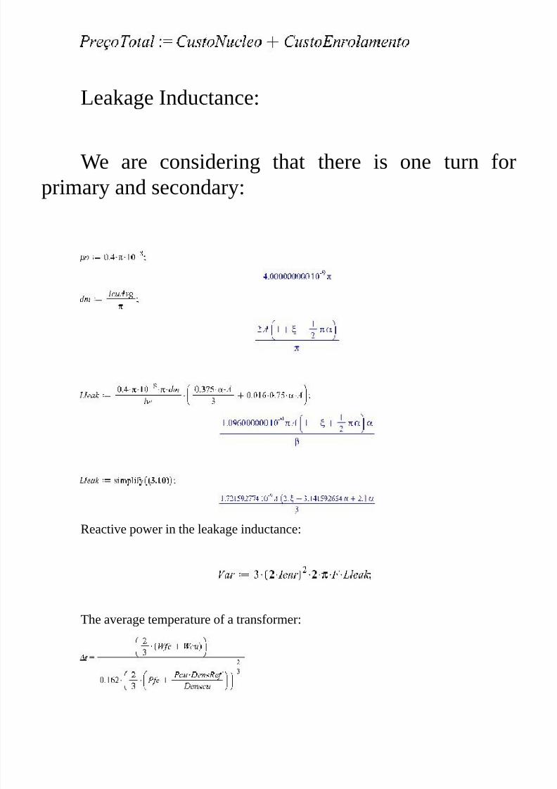
7/25/2019 Transformer's Book a Travel Over Different Aspects of Transformers, Inductors and Transductors - Humberto de So…
http://slidepdf.com/reader/full/transformers-book-a-travel-over-different-aspects-of-transformers-inductors 242/304
Leakage Inductance:
We are considering that there is one turn for
primary and secondary:
Reactive power in the leakage inductance:
The average temperature of a transformer:

7/25/2019 Transformer's Book a Travel Over Different Aspects of Transformers, Inductors and Transductors - Humberto de So…
http://slidepdf.com/reader/full/transformers-book-a-travel-over-different-aspects-of-transformers-inductors 243/304
(5.1)
Isolating Di2:
Calculating the core cost:
Calculating the coil cost:
Total cost:

7/25/2019 Transformer's Book a Travel Over Different Aspects of Transformers, Inductors and Transductors - Humberto de So…
http://slidepdf.com/reader/full/transformers-book-a-travel-over-different-aspects-of-transformers-inductors 244/304
Setting the parameters:
Space factor of the window:
Kjan:=0.23
Density of the iron core:
Iron core density:
Ambient Temperature:
Stacking multiplier:
Core cost density:
Operation frequency:
Maximum Flux density:
Copper cost density:
Surface of cost of the solution under consideration:
A=10Cm;

7/25/2019 Transformer's Book a Travel Over Different Aspects of Transformers, Inductors and Transductors - Humberto de So…
http://slidepdf.com/reader/full/transformers-book-a-travel-over-different-aspects-of-transformers-inductors 245/304
We did not give any prior relationship that the transformer must assume. The
unique predetermined relationship is between the stack and the width of the blade leg that
is square.
This is also the main reason for our search for optimal values of the normalized
relations of the core.
In later studies we will give complete freedom to the program find the best
solution for the core that will also be the optimal value.
The figure below gives a surface where the minimum point is the best cost of the
transformer.
Now we will search for the minimum value of the cost by the Maple command
NLPsolve.
Fig. 166
Minimum cost density and Optimum Values of alpha and beta:
>

7/25/2019 Transformer's Book a Travel Over Different Aspects of Transformers, Inductors and Transductors - Humberto de So…
http://slidepdf.com/reader/full/transformers-book-a-travel-over-different-aspects-of-transformers-inductors 246/304
Minimum Cost Density=0.04593508……
Evidently this depends on unity prices in each particular country, but gives an idea
of what can be done to minimize costs by improving the relationship of measurements of
the iron core.
Voltage regulation due to leakage inductances and coil resistances:
>
The voltage regulation of this transformer, considering the parameters found is:

7/25/2019 Transformer's Book a Travel Over Different Aspects of Transformers, Inductors and Transductors - Humberto de So…
http://slidepdf.com/reader/full/transformers-book-a-travel-over-different-aspects-of-transformers-inductors 247/304
(5.17)
The resistive voltage drop:
(5.19)
The inductive voltage drop as a percentage of the output voltage:
(5.21)
We have made an introduction about optimization of the normalized relations of
the iron cores. Evidently this is apartial solution, because to get the entire figure we must
to parameterize the A and x , searching the minimum price. In reality there are two far
values for minimum prices but this is the question for the third volume of our book where
we will discuss about general conditions for optimizations.
The optimization of the core corresponds for each power. Depending structure of
the transformer, for example: In one project of an UPS of 500Kva the transformer usesduct for refrigeration. This is another kind of study.
Bellow we can see the coil simplified drawing of this transformer. In the drawing,
at the left side up, can be seen the refrigeration ducts. This is a special case, because this
transformer needed to handle harmonics and many other factor must be accounted. We are
considering this in the third volume:

7/25/2019 Transformer's Book a Travel Over Different Aspects of Transformers, Inductors and Transductors - Humberto de So…
http://slidepdf.com/reader/full/transformers-book-a-travel-over-different-aspects-of-transformers-inductors 248/304
Fig. 167
For cruciform cores the solution is the same, however we must reference to the
internal dimensions of the core to get Alpha and Beta. The computation of the average
turn length, must be calculated as a function of the radius of the leg.
Fig. 168

7/25/2019 Transformer's Book a Travel Over Different Aspects of Transformers, Inductors and Transductors - Humberto de So…
http://slidepdf.com/reader/full/transformers-book-a-travel-over-different-aspects-of-transformers-inductors 249/304
K Factor and K Factor transformers

7/25/2019 Transformer's Book a Travel Over Different Aspects of Transformers, Inductors and Transductors - Humberto de So…
http://slidepdf.com/reader/full/transformers-book-a-travel-over-different-aspects-of-transformers-inductors 250/304
The problem of the loads and the current spectrum
Today in the industry in modern data centers, telecommunication sites and even
office buildings, there are a wide use of information technology equipments and even
power control equipments that require large power. Unfortunately, most of them have non-
linear power supplies that inject harmonics in the power grid.
The great inconvenience of the harmonic injection is that leads not only to low
power factors, but to the creation of additional losses which can often bring the electrical
system to fail.
The measure of the harmonic content is the most important value in dimensioning
of the energy system. There are many solutions to mitigate the harmonics in power, but
their majority is expensive and in many cases impossible of being used mainly by space
consumption, cost and other additional factors.
The transformers are the most sensible apparatus of the system, because the
content of harmonics injected in the line, directly leads to very high dissipation.
Its detrimental effects increase with the square of the harmonic number, as the
losses involving skin depth like proximity and strange effects, and other sensitive to the
square of the product of the intensity of each, with their harmonic number. They create
large power losses that can lead them to a fire.
Underwriters Laboratories (UL) recognized the potential safety hazardous
associated with the using standard transformers with nonlinear loads.
They developed a rating system to indicate the capability of a transformer to
handle a specified harmonic content. The rating described in UL 1561 is known as K
factor transformers. UL derived K factor transformers from the information contained inANSI/IEEE STD C57.110 “IEEE recommended practice for establishing transformers
capability when supplying non sinusoidal load currents”
K factor transformers are designed to reduce the heating effects of the harmonic
currents developed by the non linear loads.

7/25/2019 Transformer's Book a Travel Over Different Aspects of Transformers, Inductors and Transductors - Humberto de So…
http://slidepdf.com/reader/full/transformers-book-a-travel-over-different-aspects-of-transformers-inductors 251/304
The K Factor definition:
The K factor as defined by IEEE 110-1992 is:
The k factor applies exclusively to transformers it is a weighted of average of
harmonic current magnitudes. Increased higher order harmonics will greatly increase K
factor. This represents the heating effects of harmonic induced eddy currents in winding
conductors.
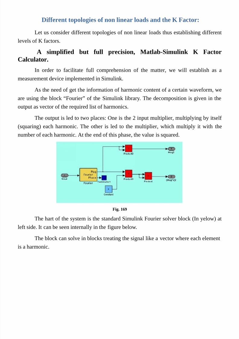
7/25/2019 Transformer's Book a Travel Over Different Aspects of Transformers, Inductors and Transductors - Humberto de So…
http://slidepdf.com/reader/full/transformers-book-a-travel-over-different-aspects-of-transformers-inductors 252/304
Different topologies of non linear loads and the K Factor:
Let us consider different topologies of non linear loads thus establishing different
levels of K factors.
A simplified but full precision, Matlab-Simulink K Factor
Calculator.
In order to facilitate full comprehension of the matter, we will establish as a
measurement device implemented in Simulink.
As the need of get the information of harmonic content of a certain waveform, we
are using the block “Fourier” of the Simulink library. The decomposition is given in the
output as vector of the required list of harmonics.
The output is led to two places: One is the 2 input multiplier, multiplying by itself
(squaring) each harmonic. The other is led to the multiplier, which multiply it with the
number of each harmonic. At the end of this phase, the value is squared.
Fig. 169
The hart of the system is the standard Simulink Fourier solver block (In yelow) at
left side. It can be seen internally in the figure below.
The block can solve in blocks treating the signal like a vector where each element
is a harmonic.
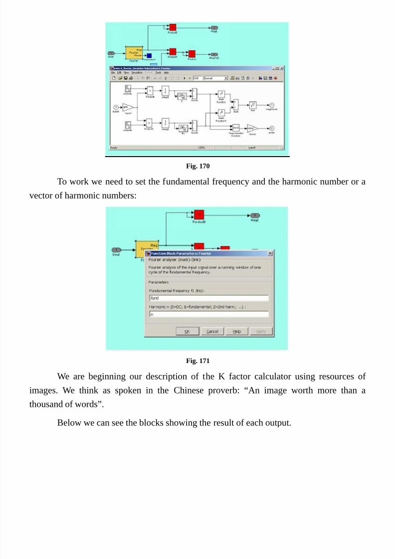
7/25/2019 Transformer's Book a Travel Over Different Aspects of Transformers, Inductors and Transductors - Humberto de So…
http://slidepdf.com/reader/full/transformers-book-a-travel-over-different-aspects-of-transformers-inductors 253/304
Fig. 170
To work we need to set the fundamental frequency and the harmonic number or a
vector of harmonic numbers:
Fig. 171
We are beginning our description of the K factor calculator using resources of
images. We think as spoken in the Chinese proverb: “An image worth more than a
thousand of words”.
Below we can see the blocks showing the result of each output.

7/25/2019 Transformer's Book a Travel Over Different Aspects of Transformers, Inductors and Transductors - Humberto de So…
http://slidepdf.com/reader/full/transformers-book-a-travel-over-different-aspects-of-transformers-inductors 254/304
Fig. 172
We transformed the block obove in a subsystem as shown below. The mask of the
subsystem includes the variables needed by the fourier block.
Fig. 173 The model needs to define de vector with the harmonic numbers that the module has to calculate.
As can be seen, the harmonic number is supplied as a vector with the harmonic
numbers required from 1 (Hidden) up to 45nth.
Other operations are done and finally we can get the K factor:

7/25/2019 Transformer's Book a Travel Over Different Aspects of Transformers, Inductors and Transductors - Humberto de So…
http://slidepdf.com/reader/full/transformers-book-a-travel-over-different-aspects-of-transformers-inductors 255/304
Fig. 174 In this figure is shown the values calculated for each output
We completed our instrument, implementing a Wattmeter, a VA meter a Power
factor meter and a displacement factor meter. All will be used for analysis of different
kinds of loads.
Fig. 175
We must work first with our first load. They are present in each personal computer
in our houses, offices and many more other places.
There are variations of them with and input power factor converter, but they are
only few among many others.
Its use is very harmful for the power mains, mainly for transformers. Fortunately
the majority of the loads of a building are of almost linear nature.
But the problem can be serious when there are many distribution transformers
segregated from the rest of the mains, feeding only loads of information equipment.

7/25/2019 Transformer's Book a Travel Over Different Aspects of Transformers, Inductors and Transductors - Humberto de So…
http://slidepdf.com/reader/full/transformers-book-a-travel-over-different-aspects-of-transformers-inductors 256/304
The IEC 62040 standard for UPS systems and the non linear
input interface power supply for personal computers.
This power supply works with a single phase rectifier with the values defined by
IEC62040 for each power, and a switching mode power supply bringing down the
voltages to the levels and powers required by the information equipment.
Fig. 176
We first are using a model of approximately 12Kva (To simulate a combination of
many power supplies in parallel, because our main purpose is to define the K factor of
them.
Let’s make the measurement getting this information, and as a second step we can
make an arrangement of a three phase configuration to measures neutral current.

7/25/2019 Transformer's Book a Travel Over Different Aspects of Transformers, Inductors and Transductors - Humberto de So…
http://slidepdf.com/reader/full/transformers-book-a-travel-over-different-aspects-of-transformers-inductors 257/304
Fig. 177 System in SimPower and Simulink arranged for testing and get our values
Results of the simulation:
Input Voltage: 220 Vac
Rms Current: 54.31 A
K Factor: 12.79
The values encountered are:
Real Power: 7887 Watts
Apparent Power: 11950VA
Power Factor: 0.6601
Displacement Factor: 0.9985

7/25/2019 Transformer's Book a Travel Over Different Aspects of Transformers, Inductors and Transductors - Humberto de So…
http://slidepdf.com/reader/full/transformers-book-a-travel-over-different-aspects-of-transformers-inductors 258/304
The effect on the neutral current
Now we can see this same power supply distributed in three phase configuration to
see the neutral current:
Fig. 178 The Phase and neutral current waveforms
The harmful effect of the neutral current: 94.07 A RMS of third Harmonic.
Let’s consider a transformer of 100 Kva with 2.5% of total impedance supplying a
system with 3 power supplies same as those presented in the anterior example. The effect
over the K factor will be shown.

7/25/2019 Transformer's Book a Travel Over Different Aspects of Transformers, Inductors and Transductors - Humberto de So…
http://slidepdf.com/reader/full/transformers-book-a-travel-over-different-aspects-of-transformers-inductors 259/304
Fig. 179
Now we can see that with the effect of the transformer, even with 100 Kva and
2.5% of series impedance with mostly inductive effect, the K factor decreased for 12.15.
Very close to the value considered in the major part of specifications for this kind of
apparatus. Evidently in the physical installations like sites of data centers where there are
many transformers, circuit breakers cables and so forth, the impedance will be
significantly higher than we have arbitrated. A thing became very clear: the neutral cables
in this kind of installation must be double of the size of the phase cables.
Before entering the K factor transformers project we need to consider other power
apparatus used, because we need to analyze them carefully.
In most installations on sites involving power sources, there are many UPS
systems that often do not consider the harmful effects that their rectifiers may pose to the
commercial power grid.
I have seen many UPS rectifier of very large manufacturers, including equipment
that features high reliability, but the rectifiers of its UPS are made without any knowledge
of polyphase rectification. They seem to be designed by beginners, without any
knowledge of power electronics. They present very poor input power factors andharmonics spectra very harmful for the commercial line.
At the moment we are entering only to talk of a few topologies. Our present

7/25/2019 Transformer's Book a Travel Over Different Aspects of Transformers, Inductors and Transductors - Humberto de So…
http://slidepdf.com/reader/full/transformers-book-a-travel-over-different-aspects-of-transformers-inductors 260/304
concern is to obtain K factor values for our projects. But in a special section we will cover
transformers for high power rectifiers; there we will talk about such subjects. In those
studies we must define the current waveforms of each winding and their mobile magnetic
portions that mean, descend deeper into these matters.
The portion mentioned above is that one part of the H profile that lies between zero
and the maximum value of H, as defined in page 73. Following the behavior of the
transformer the H profile can move depending the combination of the contribution of the
field of different coils. With such movement the other parameters of the transformer can
change according with the change of the portion. An method of “averaging” can be done
that can affect the calculation of the transformer.
By now let´s study the K factor for other topologies, at the moment a three phase 6
and 12 pulses controlled rectifiers will be used.
First of all let’s consider the fig 180 where we have a 6 pulse non controlled
rectifier with a current source simulating an infinite inductance as a load.

7/25/2019 Transformer's Book a Travel Over Different Aspects of Transformers, Inductors and Transductors - Humberto de So…
http://slidepdf.com/reader/full/transformers-book-a-travel-over-different-aspects-of-transformers-inductors 261/304
Fig. 180
Fig. 181
The line current is:
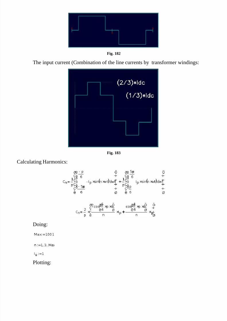
7/25/2019 Transformer's Book a Travel Over Different Aspects of Transformers, Inductors and Transductors - Humberto de So…
http://slidepdf.com/reader/full/transformers-book-a-travel-over-different-aspects-of-transformers-inductors 262/304
Fig. 182
The input current (Combination of the line currents by transformer windings:
Fig. 183
Calculating Harmonics:
Doing:
Plotting:

7/25/2019 Transformer's Book a Travel Over Different Aspects of Transformers, Inductors and Transductors - Humberto de So…
http://slidepdf.com/reader/full/transformers-book-a-travel-over-different-aspects-of-transformers-inductors 263/304
Fig. 184
Calculating K Factor:
In this case, such equation do not converges to a value, being totally dependent to
the number of harmonics. This is due to the sharpness of the square wave that presents low
decay of harmonics added to the product of the amplitude of the harmonic by its number.
Such product tends to be constant.
We can observe that in the first graph the decay of the harmonic is dependent of
1/n. It’s clear that if we multiply each one per n, the result is maintained constant up to
infinity.

7/25/2019 Transformer's Book a Travel Over Different Aspects of Transformers, Inductors and Transductors - Humberto de So…
http://slidepdf.com/reader/full/transformers-book-a-travel-over-different-aspects-of-transformers-inductors 264/304
Fig. 185
We will be using this series for the study of high power rectifiers where do not
exists this kind of product, due to the fact that the application do not exist need for the
calculation of harmonic product by its harmonic number. In the real rectifier there is thecommutation angle created by the impedance of the transformer and power line that forces
the decay of harmonics, making possible the convergence of the harmonic series: We will
be seeing this in the high power rectifiers.
By now we will be using simulation in Mathlab that is straight forward and
sufficient precise because they are numerical solutions of the formulas involved. Even in
power systems, because the solutions involve state equations and are very close to the
mathematical solutions. In the past we have used state equations conjugated with Petri
Nets
We are performing the simulation simultaneously in three rectifiers. One is a 12
pulses rectifier and the other two, 6 pulses rectifiers. The difference between the two is the
arrangement of the secondary’s where one is delta and the other is star. This promotes
different current waveforms as can be observed in the two oscillograms at below right of
the figure. Despite the different waveforms is maintained the equality of spectrum, and
therefore is maintained same K factor.
We have used same unit impedances in the simulation of the rectifiers and such

7/25/2019 Transformer's Book a Travel Over Different Aspects of Transformers, Inductors and Transductors - Humberto de So…
http://slidepdf.com/reader/full/transformers-book-a-travel-over-different-aspects-of-transformers-inductors 265/304
impedances are those ones employed in the characteristics rectifiers used for those
purposes.
In the figure 186 we have the two rectifiers and the resultant waveforms. The
oscilloscopes in the right side of the figures show the waveforms of the input currents.
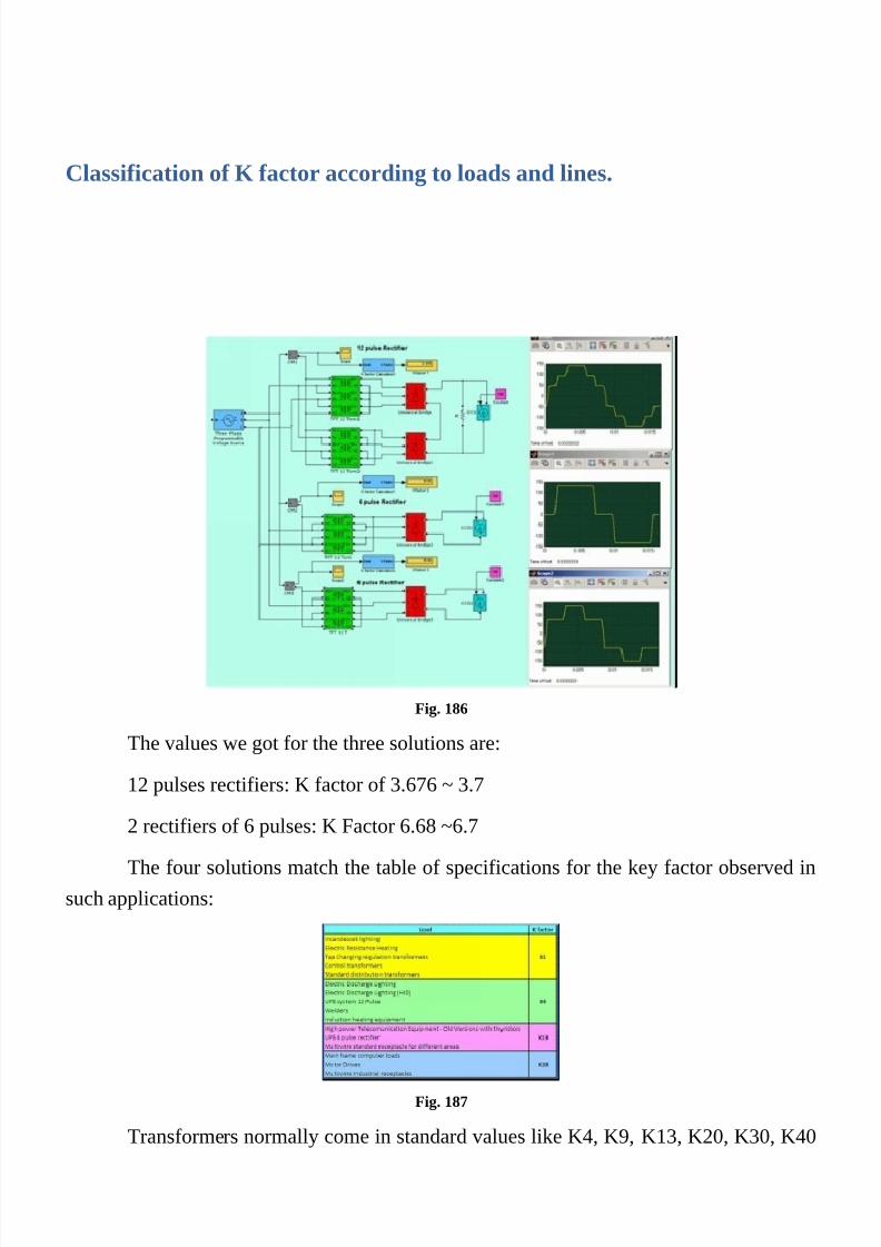
7/25/2019 Transformer's Book a Travel Over Different Aspects of Transformers, Inductors and Transductors - Humberto de So…
http://slidepdf.com/reader/full/transformers-book-a-travel-over-different-aspects-of-transformers-inductors 266/304
Classification of K factor according to loads and lines.
Fig. 186
The values we got for the three solutions are:
12 pulses rectifiers: K factor of 3.676 ~ 3.7
2 rectifiers of 6 pulses: K Factor 6.68 ~6.7
The four solutions match the table of specifications for the key factor observed in
such applications:
Fig. 187
Transformers normally come in standard values like K4, K9, K13, K20, K30, K40

7/25/2019 Transformer's Book a Travel Over Different Aspects of Transformers, Inductors and Transductors - Humberto de So…
http://slidepdf.com/reader/full/transformers-book-a-travel-over-different-aspects-of-transformers-inductors 267/304
and K50.
The first problem is the definition of the spectral figure coming from a defined K
factor number.
We defined a universal oscillator that can be settled for each K factor used in
calculations of transformers. In reality there isn’t a fixed determination of a particular“Waveform” and the own definition of the K factor do not guarantee any spectrum in
particular, do not existing also any limit for the number of the harmonics. Evidently the
main interest of the standard is to guarantee the limitation of the eddy currents generated
inside the electrical conductors by proximity and skin depth effects.
In the present case, we can define a table of certain values of Kfactor and our
“Second term”, that is calculated by the “Waveform Term Calculator as stated in the
chapter xx.
Firstly let’s define a structure for the determination of our values: In this system
there are 5 waveform generators with K4,K9,K13,K20 and K30 that are the most used
standard for K Factor transformers. For each one there is a K factor calculator and a
waveform term calculator (Second term calculator).
With this system we are making a survey of the second term for each k factor.
Fig. 188 Kfactor and Second Term Table

7/25/2019 Transformer's Book a Travel Over Different Aspects of Transformers, Inductors and Transductors - Humberto de So…
http://slidepdf.com/reader/full/transformers-book-a-travel-over-different-aspects-of-transformers-inductors 268/304
Fig. 189

7/25/2019 Transformer's Book a Travel Over Different Aspects of Transformers, Inductors and Transductors - Humberto de So…
http://slidepdf.com/reader/full/transformers-book-a-travel-over-different-aspects-of-transformers-inductors 269/304
Formulas group:
Or:
Where:

7/25/2019 Transformer's Book a Travel Over Different Aspects of Transformers, Inductors and Transductors - Humberto de So…
http://slidepdf.com/reader/full/transformers-book-a-travel-over-different-aspects-of-transformers-inductors 270/304
Sample project of a 50Kva three Phase distribution transformer for
Kfactor = 13
Let’s make an example of a transformer distribution of 50 Kva of Kfactor=13.
The input is a three phase line of 380 Vca delta connection.
The output voltage is a three phase 127/220 Vca star connection.
The frequency is 60Hz.
The coil of the transformer is of aluminum.
The flux density is of 15000 Gausses.
First of all we see a problem at first glance. What is the kfactor of the current in the
delta primary of this distribution transformer?
Exactly the same, because the transformation is done, involving only the secondary
for the primary in one leg. This, do not interfere in the spectral composition of the
waveform.
With all those, let’s calculate our transformer:
We have to apply the stacking factor in order to get the net stack for the magnetic
calculation.
Magnetic Cross sectional area:

7/25/2019 Transformer's Book a Travel Over Different Aspects of Transformers, Inductors and Transductors - Humberto de So…
http://slidepdf.com/reader/full/transformers-book-a-travel-over-different-aspects-of-transformers-inductors 271/304

7/25/2019 Transformer's Book a Travel Over Different Aspects of Transformers, Inductors and Transductors - Humberto de So…
http://slidepdf.com/reader/full/transformers-book-a-travel-over-different-aspects-of-transformers-inductors 272/304

7/25/2019 Transformer's Book a Travel Over Different Aspects of Transformers, Inductors and Transductors - Humberto de So…
http://slidepdf.com/reader/full/transformers-book-a-travel-over-different-aspects-of-transformers-inductors 273/304

7/25/2019 Transformer's Book a Travel Over Different Aspects of Transformers, Inductors and Transductors - Humberto de So…
http://slidepdf.com/reader/full/transformers-book-a-travel-over-different-aspects-of-transformers-inductors 274/304

7/25/2019 Transformer's Book a Travel Over Different Aspects of Transformers, Inductors and Transductors - Humberto de So…
http://slidepdf.com/reader/full/transformers-book-a-travel-over-different-aspects-of-transformers-inductors 275/304

7/25/2019 Transformer's Book a Travel Over Different Aspects of Transformers, Inductors and Transductors - Humberto de So…
http://slidepdf.com/reader/full/transformers-book-a-travel-over-different-aspects-of-transformers-inductors 276/304
Below in the next page, can be seen the 3 figures of the transformer coil. There can
be found the values of the average magnetic path of the secondary and primary.
Additionally can be seen in the third drawing the side margin ML in the two sides of the
coil.

7/25/2019 Transformer's Book a Travel Over Different Aspects of Transformers, Inductors and Transductors - Humberto de So…
http://slidepdf.com/reader/full/transformers-book-a-travel-over-different-aspects-of-transformers-inductors 277/304
Fig. 190
Fig. 191

7/25/2019 Transformer's Book a Travel Over Different Aspects of Transformers, Inductors and Transductors - Humberto de So…
http://slidepdf.com/reader/full/transformers-book-a-travel-over-different-aspects-of-transformers-inductors 278/304
Fig. 192
Fig. 193

7/25/2019 Transformer's Book a Travel Over Different Aspects of Transformers, Inductors and Transductors - Humberto de So…
http://slidepdf.com/reader/full/transformers-book-a-travel-over-different-aspects-of-transformers-inductors 279/304
Fig. 194
Due to the impossibility of choosing an exactly thickness for a defined optimal “d”
calculated, certain considerations must be done in order we get more advantageous results.
Let’s see with more accuracy our definition of the bar used in our project:
We have seen that the Dopt was 4.13 but by virtue of practicity, we must use
standard bars, we have chosen a 3.969 height bar. What this means? We could have
selected another one with bigger dimension. Why we have chosen this one?
To see why, we need plot the graph to see the consequences of the variation of the
relation and see why we decided so.
Making:
We can plot it:

7/25/2019 Transformer's Book a Travel Over Different Aspects of Transformers, Inductors and Transductors - Humberto de So…
http://slidepdf.com/reader/full/transformers-book-a-travel-over-different-aspects-of-transformers-inductors 280/304
Fig. 195
Can be seen in fig 195 that we can choose in the two sides around the optimal
point and the better are the left side ones, because we can use less conductor weight and
consequently cheaper and also occupying less space.
Do not worry about the dimension of the vertical axis because it’s only a relative
measure:

7/25/2019 Transformer's Book a Travel Over Different Aspects of Transformers, Inductors and Transductors - Humberto de So…
http://slidepdf.com/reader/full/transformers-book-a-travel-over-different-aspects-of-transformers-inductors 281/304
Solutions for skin depthThe obvious reason about the replacement of the solid conductor by a Litz Wire:
The use of this conductor is due to the fact that
of an improvement in the use of multiple areas of the
conductors by individually possess better ratio d/ d .
There is also the fact that multiple conductors, by
twisting, to submerge several times in different field
gradients H, creating
eddy currents in lower locations, thereby reducing
losses. The angle of twist and the settings are veryimportant. There is Litz wire “True” and “False”. The
true litz wire, are twisted of twisted of twisted yarn
twist … in various hierarchies, in a perfectly defined
prescription, causing all conductors to pass through all
positions, ensuring in addition to other effects, current
equalization.
False, they are only twisted and do not guarantee that all wires pass through
everywhere. The simple twisted wire or “False Litz wire” is known in the English
language as “bunched WIRE”. In this paper these two forms will be indistinctly called
“Litz wire”.
Perhaps the most obvious way to reduce skin effect losses are by using the classic
“Litz wire” (TWISTED WIRE).
If a circular conductor is replaced by a Litz wire twisted-n, it can be assumed that
the wire was replaced by a square conductor divided by a number of layers equal to the
square root of n.

7/25/2019 Transformer's Book a Travel Over Different Aspects of Transformers, Inductors and Transductors - Humberto de So…
http://slidepdf.com/reader/full/transformers-book-a-travel-over-different-aspects-of-transformers-inductors 282/304
Fig. 196
Skin effect at strand level:
Fig. 197
We note that the effects produced in one conductor are duplicated in groups of
conductors.
The skin depth effect observed in a conductor, can likewise be seen in groups ofconductors, the obstruction to penetration of the magnetic field works like they were a
solid conductor.
Fig. 198 – Proximity effect at bundle level

7/25/2019 Transformer's Book a Travel Over Different Aspects of Transformers, Inductors and Transductors - Humberto de So…
http://slidepdf.com/reader/full/transformers-book-a-travel-over-different-aspects-of-transformers-inductors 283/304
Fig. 199 – Proximity effect at strand level
Proximity effect at bundle level:
There are circulating currents (Eddy currents) in conductors produced by external f
Fig. 200
The Litz wire is by far the most effective way to reduce high frequency losses for
waveform close to sinusoidal. 120 twisted conductors, can reduce the losses of 42% can
be obtained by solid wire for triangular waveforms to 70% square wave and pulsed current
to 85%.
If the conductors of the twisted litz wire are too thick, the losses can be much
larger than the solid conductors (Due to proximity effects to multiple layers)

7/25/2019 Transformer's Book a Travel Over Different Aspects of Transformers, Inductors and Transductors - Humberto de So…
http://slidepdf.com/reader/full/transformers-book-a-travel-over-different-aspects-of-transformers-inductors 284/304
Conductor plate or foil
The use of the copper plate is intended to reduce the thickness of the conductor,
thereby maintaining its area. This decrease in thickness of the conductor plate is possible
by having the width equal to the width of the window.
Using plate or foil decreases the thickness of the conductor, improving the ratio d /
δ.
Winding plate or foil results in the greatest possible number of layers, for a given
number of turns (assuming a single layer solid conductor), which only minimize losses if
the thickness of the conductor is optimum.
The use o aluminum plate or foil is a good idea in the replacement of copper due tothe fact that the increase of the skin depth produced by this metal pays off partially the
effect of the resistivity but using a metal less heavy and cheaper.

7/25/2019 Transformer's Book a Travel Over Different Aspects of Transformers, Inductors and Transductors - Humberto de So…
http://slidepdf.com/reader/full/transformers-book-a-travel-over-different-aspects-of-transformers-inductors 285/304
Interleaving winding
Interleaving windings increases the number of “Portions” (This can create
problems with available window size). The average loss (Net) can be reduced by this
practice due to reduced amplitudes in the profile of FMM that reduces the field to which
the portions are submitted and consequently reducing the circulating currents. This is
without a doubt one of the most effective skin effect and eddy current loss reduction
means at the highest levels of power.

7/25/2019 Transformer's Book a Travel Over Different Aspects of Transformers, Inductors and Transductors - Humberto de So…
http://slidepdf.com/reader/full/transformers-book-a-travel-over-different-aspects-of-transformers-inductors 286/304
Winding Construction for Minimum Losses:
Avoid big conductors.
Insulate attaching screws that passes through high field, including those ones that
pass inside the core.
Avoid using metal parts inside the windings that do not work as coils. They
produce strange effect.
Make a current confrontation where possible.
Use conductor sheet, plate or equivalent.
Use Litz wire.

7/25/2019 Transformer's Book a Travel Over Different Aspects of Transformers, Inductors and Transductors - Humberto de So…
http://slidepdf.com/reader/full/transformers-book-a-travel-over-different-aspects-of-transformers-inductors 287/304
Planar Windings
The planar winding is without a doubt the most suitable for very high frequency
operations (In the range of megahertz) as the windings may be constructed from printed
circuit plates where the copper layers are extremely thin (17 microns, 35 microns, 70
microns, or other), the windings can be intercalated with great ease, and consequently to
use the conduction on both sides possibly no reverse currents (Optimum confrontation).
Fig. 202

7/25/2019 Transformer's Book a Travel Over Different Aspects of Transformers, Inductors and Transductors - Humberto de So…
http://slidepdf.com/reader/full/transformers-book-a-travel-over-different-aspects-of-transformers-inductors 288/304
7/25/2019 Transformer's Book a Travel Over Different Aspects of Transformers, Inductors and Transductors - Humberto de So…
http://slidepdf.com/reader/full/transformers-book-a-travel-over-different-aspects-of-transformers-inductors 289/304
REFERENCES
[1]P.L. Dowell: Effects of eddy currents in Transformer Windings: Proc. IEE Vol 113 No.
8 August 1966, Pages 1387 – 1395.
[2] P.S. Venkatraman: Winding Eddy Current Losses in Switch Mode Power Transformers
due to Rectangular Wave Currents. Proceedings of Powecon II A1. 1984 Pages 1-11
[3] Bruce Carlsten: High Frequency Conductor Losses in Switching Magnetics. HPFC
May 1986 Proccedings. Pages 155 – 176.
[4] Bruce Carsten: Calculating Skin and Proximity Effect Conductor Losses in Switching
Magnetics: PCIM International conference PCIM 95 – Monday June 19, 1995
[5] Jieli Li, Tarek Abdallah, Charles R. Sullivan. Improved Calculation of Core Loss With
Nonsinusoidal Waveforms. Darmouth College, Hanover, NH, 03755, USA.
[6]Charles R. Sullivan. Optimal Choice for number of strands in a Litz-Wire Transformer
Winding – Plenary Paper Presented ad IEEE Power Electronics Specialists Conference,
June 1997.
[7] Jiankun Hu, Charles R. Sullivan: Optimization of Shapes for Round-Wire High
Frequency Gapped- Inductor Windings: IEEE Industry Applications Society Annual
Meeting St. Louis, 12 – 16 October, 1998.
[8] Charles L. Sullivan: Optimal Choice For number of Strands in a Litz wire Transformer
Winding. IEEE Transactions of Power Electronics, Vol 14, No 2, March 1999.
[9]W.G. Hurley, E. Gath and J.G. Breslim: Optimizing the AC Resistance of Multilayer
Transformer Windings with Arbitrary Current Waveforms. Power Electronics ResearchCentre, National University of Ireland, Galway, Ireland. The work was supported by PEI
Technologies, Dublin Ireland.
[10]Jiankun Hu, Charles R. Sullivan: The Quasi Distributed Gap Technique for Planar
Inductors: Design Guidelines.Annual Meeting. IEEE Industry Application Society –
October 1997
[11] Jiankun Hu, Charles R. Sullivan. AC Resistance of Planar Power Inductors and theQuasi distributed Gap Technique. IEEE Transactions on Power Electronics Vol.16 No 4,
July 2001. Pages 558 - 567
7/25/2019 Transformer's Book a Travel Over Different Aspects of Transformers, Inductors and Transductors - Humberto de So…
http://slidepdf.com/reader/full/transformers-book-a-travel-over-different-aspects-of-transformers-inductors 290/304
[12] G.M. Stein . Influence of the Core Form Upon the Iron Losses of Transformers. AIEE
General Meeting January 26-30, 1948. Pages 95-104
[13] T.D. Gordy, H.L. Gabarino. Characteristics of Overlapping Joints in Magnetic
Circuits. AIEE General Meeting, New York. N.Y, January 21-25, 1952. Pages 386 – 392.
[13] James P. Barton. Interlamination Resistance. AIEE Summer Technical Meeting, St.Louis, Mo, June 26-30. 1944. Pages 670-671
[15] A.C. Beiler, P.L. Scmidit “Interlaminar Eddy Current Loss in Laminated Cores.”
AIEE Summer General Meeting, Montreal, Quebec, Canada, June 9-13, 1947. Pages 872-
878
[16]J.Reinert, A. brockmeyer, and R.W. De Donecker “Calculation of losses in ferro and
ferromagnetic materials based on the modified steinmetz equation”, Proceedings of 34th
Annual meeting of the IEEE Industry Application Society, 1999, pp 2087-92. Vol 3.
[17] Jieli Li. Tarek Abdallah, and Charles R. Sullivan. “Improved Calculation of Core
Loss with Nonsinusoidal Waveforms” Darmouth College, Hanover, NH, 03755 USA.
Work Supported in part by a grant from Volterm.

7/25/2019 Transformer's Book a Travel Over Different Aspects of Transformers, Inductors and Transductors - Humberto de So…
http://slidepdf.com/reader/full/transformers-book-a-travel-over-different-aspects-of-transformers-inductors 291/304
Index of all volumes
Index of Vol I
Introduction
A Brief History
What Is a Transformer?
The physics behind the scenes
Structure of the Matter and a brief view over atomic physics
Magnetism and Magnetic Materials
Magnetism
Magnetism in Materials
Ferromagnetic Materials
The ferromagnetic domains
Ferromagnetic Domains and domain walls
Initial Concepts
Ampere´s Law
Magnetization
Flux Density B
Permeability
Measurement of permeability
Amplitude permeability.
Initial Permeability, Rayleigh Constant and Rayleigh law
Absolute and relative permeability
Complex permeability
Apparent permeability

7/25/2019 Transformer's Book a Travel Over Different Aspects of Transformers, Inductors and Transductors - Humberto de So…
http://slidepdf.com/reader/full/transformers-book-a-travel-over-different-aspects-of-transformers-inductors 292/304
Differential permeability
Magnetostriction
Inductance and Inductors
What is Inductance?
Reluctance
Losses in Magnetic Materials
Losses
The measurement of losses
Representation of losses
General Losses.
Hysteresis losses
Classical losses
Excess Losses
Facts affecting the total losses
Loss behavior in different magnetic materials
Soft ferrites for high frequency applications
Searching for a general loss model which could include harmonics and DC
currents
The MSE Aproach - (Modified Steinmetz Equation)
The GSE Approach (General Steinmetz Equation)
Combination of fields
Ampere´s Law in depth
For the Sake of simplicity
Magnetic field produced by currents in endless sheets
Addition of fields in two parallel plates
Infinite Solenoid
Addition of fields in several layers

7/25/2019 Transformer's Book a Travel Over Different Aspects of Transformers, Inductors and Transductors - Humberto de So…
http://slidepdf.com/reader/full/transformers-book-a-travel-over-different-aspects-of-transformers-inductors 293/304
Two overlapping solenoids
Simulation by FEA (Finite Element Analysis)
Equivalent Circuit of a transformer
Leakage Inductance
What is leakage Inductance
The definition of a fundamental inductance equation departing from the energy
stored in magnetic field
Inductance formula definition (Toroidal Case)
Inductance Formula definition (Leakage inductance Case)
The equivalent circuit of a transformer and measurements of ACResistance
The equivalent circuit
AC resistance Measurement
Measurement of DC resistance
High frequencies response
Medium frequencies Response
Low frequencies response
Skin Depth and Proximity Effect
Skin Depth
Ampere Law in more Detail
Diffusion of magnetic field in a Conductor
Simple Rules in order to handle fields and currents in a single face.
Direction of the current
Simple Rules
Diffusion interrupted by change of field or current direction.
Proximity Effect
The proximity effect develops considerable losses.

7/25/2019 Transformer's Book a Travel Over Different Aspects of Transformers, Inductors and Transductors - Humberto de So…
http://slidepdf.com/reader/full/transformers-book-a-travel-over-different-aspects-of-transformers-inductors 294/304
Proximity Effect three-dimensional configurations
Simplifying assumptions
Consequences:
Transformation from a round conductor winding to metal plate or sheet 112
Dowell transformed circular wire windings into an “Equivalent Sheet” as follows
Eddy Currents
Forming a unique sheet
Square of the current
Second Layer
Third Layer
Fourth layer
Fifth Layer
Tenth Layer
Determination of Fr for the entire coil
Sample Calculation of AC resistance for primary and secondary windings due to
skin and proximity effect
Dowell Relations – Simplifying the figure
Expanding in series for simplification
Applicability
Skin and Proximity effects facing complex waveformsBehavior for complex waveforms
We need to treat the problem through losses
Determination of the Kr Curve
Using Kr for loss calculation
Further simplification with harmonics
First Example: Calculation of a 4 Layers transformer with Copper sheet in the two
coils

7/25/2019 Transformer's Book a Travel Over Different Aspects of Transformers, Inductors and Transductors - Humberto de So…
http://slidepdf.com/reader/full/transformers-book-a-travel-over-different-aspects-of-transformers-inductors 295/304
Second example: Calculating ht losses:
Another method for the calculation of Fr
Solution other than for paper and pencil:
Calculation in the design of a 20Kva inverter filter inductor
Design of a ferrite 3Kva, 200Khz power transformer for a ZVS-QRC
telecommunication SMPS.
The Gap Losses - The approach.
The visual effect of the gaps
Determination of losses by finite elements
The calculation of losses in Litz Wires
The problem of the size
The definition of the equation that determines the flux density B, departing from
frequency, voltage and magnetic cross sectional area of the core
EI Core transformer
Calculating over a single Phase EI lamination transformer
Determination of the better cost for a three phase transformer
K Factor and K Factor transformers
The problem of the loads and the current spectrum
The K Factor definition
Different topologies of non linear loads and the K Factor
A simplified but full precision Matlab-Simulink K Factor Calculator
The IEC 62040 standard for UPS systems and the non linear input interface power
supply for personal computers
The effect on the neutral current
Classification of K factor according to loads and lines
Formulas group
Sample project of a 50Kva three Phase distribution transformer for Kfactor = 13

7/25/2019 Transformer's Book a Travel Over Different Aspects of Transformers, Inductors and Transductors - Humberto de So…
http://slidepdf.com/reader/full/transformers-book-a-travel-over-different-aspects-of-transformers-inductors 296/304
Solutions for skin depth
Conductor plate or foil
Interleaving winding
Winding Construction for Minimum Losses
Planar Windings
REFERENCES. Of the Vol I
Index of Vol II
A survey of different magnetic materials and cores
E I Cores for small Transformers
Pulverization and lamination needs for Eddy currents reduction and skin depth
partial solution.
C Cores and C Composed cores for medium Power transformers
The problems of compositionComposed lamination for high power transformers
Cruciform cored transformers, optimization and the minimum degree
Simulations essays using FEA to see the behavior of the compositions
The importance of the definition of lamination standards
The Ferrite cores
The Powder Cores
MPP
High FluX
Kool Mu
X Flux
Vitroperm cores for High frequency transformers
Nanocrystaline cores for MagAmp

7/25/2019 Transformer's Book a Travel Over Different Aspects of Transformers, Inductors and Transductors - Humberto de So…
http://slidepdf.com/reader/full/transformers-book-a-travel-over-different-aspects-of-transformers-inductors 297/304
Metglass Magnetic Alloys
MicroMetals Powder Cores
The Exciting current of a transformer.
The magnetizing current (inductive part)
The real part
The problem of the inrush current
The effect of magnetic memory of the core
The problem of the initial value
The value of the saturation and the slope of the curve
The profile of the inrush current
The sympathetic inrush current
The magnetic pulse outside the transformer due to the inrush (Dangerous
Consequences)
Transformers like a Voltage or Current power supply.
Transformer as a voltage source
The problem of the voltage regulation
The voltage accuracy as a potential measurement transformer
The transformer as a current source
The problem of the current regulation
The current accuracy as a current measurement transformer

7/25/2019 Transformer's Book a Travel Over Different Aspects of Transformers, Inductors and Transductors - Humberto de So…
http://slidepdf.com/reader/full/transformers-book-a-travel-over-different-aspects-of-transformers-inductors 298/304
The problem of Temperature
The external area approach (Average temperature)
The weight and loss approach (Average Temperature)
Calculation of temperature drop between layers
Temperature measurement of power transformers
Temperature measurement at light load and nominal voltage
Temperature measurement at nominal load and low voltage
The size and weight versus temperature time constant and the transient thermal
impedance.
The complete thermal model of a transformer. Involving power losses, dissipation
and thermal feedback. Using Simulink, Simscape and Thermal elements
The hot spots ant their measurement.
The forced cooling of transformers
Power Transformer optimization
The point of maximum efficiency
The curve of maximum point efficiency: maximum copper weight side or
maximum core weight side.
Optimization constraints
By temperature
By Voltage Regulation
By special dimensions
By Cost
By efficiency

7/25/2019 Transformer's Book a Travel Over Different Aspects of Transformers, Inductors and Transductors - Humberto de So…
http://slidepdf.com/reader/full/transformers-book-a-travel-over-different-aspects-of-transformers-inductors 299/304
By impedance
The problem of skin and proximity effect in high power transformers
The orthogonality between proximity and skin effect
The exact calculation of proximity effect
The exact calculation of skin effect
Th simplified approach
Polyphase Transformers and High power polyphase Rectifiers
Three Phase Transformers
The rectification
The commutation principle
The commutation angle calculation for different configurations
Delta open and scott Transformers
Zig-Zag Topologies
Multiple Zig-Zag Topologies
Extended delta topologies
The transformers for high power industrial rectifiers and multiple topologies
The problem of multiple waveforms in the windings for polyphase topologies
The calculations of additional losses due to proximity skin effect in multiplewindings at different waveforms.
The end Effect
Demonstration of the end effect by FEA (Finite Elements Analysis)
Causes
A thermographic photo showing the end effect

7/25/2019 Transformer's Book a Travel Over Different Aspects of Transformers, Inductors and Transductors - Humberto de So…
http://slidepdf.com/reader/full/transformers-book-a-travel-over-different-aspects-of-transformers-inductors 300/304
The difficulty to find a solution
A difficulty for partial solution
The strange effect
Who is the strange?
Strange effect Calculation
Definitions
Solutions
Planar Transformers and inductors
The planar approach
The windings problems and solutions
The printed circuit winding
Multiple printed circuit winding and flexible printed circuits
Interleaving coil and its effects over the H profile and the improvement of losses
Calculations of Additional losses due to skin proximity effect
Copper or aluminum Foil for high power solutions
The planar inductor, limitation by the fixed H profile
Planar solutions
REFERENCES. Of the Vol II
Index Vol III

7/25/2019 Transformer's Book a Travel Over Different Aspects of Transformers, Inductors and Transductors - Humberto de So…
http://slidepdf.com/reader/full/transformers-book-a-travel-over-different-aspects-of-transformers-inductors 301/304
Designing mains medium power Transformer (500KVA) using the
(Cost Constraint algorithm).
The problems involved
Concluding; the usage of copper or aluminum.
Optimizing the height of the coil.
One simple mathematical, Matlab and Simulink Model for power transformers
calculations
Designing a power choke of various tenths of KVAR using planar
topology to solve gaps problems.
The geometric problem
Construction problems
Calculation of losses
Demonstrating the results by FEA
Designing a selective 500Khz power supply inductor with 2
different conductors.
Designing the inductor with Wire
Designing the inductor with foils
Calculating the inductor and concluding the impossibility to go ahead.
Installing a very thin conductor in parallel that solves the problem
Calculations to see the solution
Designing the same 500Khz power supply inductor with Printed
circuit planar multilayer solution.
Transductors and magnetic Amplifiers (MagAmp)
The transductor – The revival from the grave - A forgotten theory

7/25/2019 Transformer's Book a Travel Over Different Aspects of Transformers, Inductors and Transductors - Humberto de So…
http://slidepdf.com/reader/full/transformers-book-a-travel-over-different-aspects-of-transformers-inductors 302/304
Mean voltage and flux changes
Addition of mean fluxes
Energy Storage in magnetic Cores
Summary of useful relationships
Basic operation of the transductors
Characteristic of a transductor
Control Ratio
Free magnetization transductor.
Forced magnetization transductor.
Supply Voltage
Power Output
Power amplification
Sel-Excited transductor
AC Magnetization Curve
Form Factor and waveforms of load current
Efficiency
Transient and steady-state operation of idealized transductors
Simplification of the magnetization curve
Voltage-time integral
Basic circuit equations
The self excitation
Mean fluxes and transductor Voltages
The self excited Transductors
Limitations of the simplified treatment

7/25/2019 Transformer's Book a Travel Over Different Aspects of Transformers, Inductors and Transductors - Humberto de So…
http://slidepdf.com/reader/full/transformers-book-a-travel-over-different-aspects-of-transformers-inductors 303/304
Action of the self excitation rectifier
Amplification of the self excited transductor in the steady state
The amperes turn ratio
The control characteristic
Transductors with auto excitation
Circuit operation of auto excited transductors
Singularity theorem for auto excited transductors.
Ampere turn ratio of auto excited transductors
Transductors with reactive Loads
Transient and frequency response of transductors
High speed transductors and magnetic amplifiers
Multi stage Magnetic Amplifiers
The new solutions for SMPS.
The regulation and control circuits
The simplicity of the regulation circuits
Appendix A

7/25/2019 Transformer's Book a Travel Over Different Aspects of Transformers, Inductors and Transductors - Humberto de So…
http://slidepdf.com/reader/full/transformers-book-a-travel-over-different-aspects-of-transformers-inductors 304/304
Appendix B


![Primera Conferencia Humberto Maturana[1]](https://static.fdocuments.in/doc/165x107/544e8145af7959dd1e8b4996/primera-conferencia-humberto-maturana1.jpg)