TRAFFIC BARRIER GUIDELINES - Illinois Tollway
139
Transcript of TRAFFIC BARRIER GUIDELINES - Illinois Tollway


TRAFFIC BARRIER GUIDELINES
MARCH 2021 | ILLINOIS TOLLWAY | i
This Illinois Tollway Traffic Barrier Guidelines dated March 2021 replaces the previous version dated March 2020.
List of Major Revisions: This version of the Illinois Tollway Traffic Barrier Guidelines has some significant changes to the version it replaces. Major revisions are listed below.
Section 1. Introduction
Article 1.1 – Clarified the intent of the manual is to apply to Illinois Tollway facilities that are open to Tollway patrons and does not apply to low-speed facilities such as parking lots and service roads.
Article 1.2 and 1.3 – Added an acronym and definition for the End of Need (EON). Made a few minor corrections to other definitions to improve consistency between the IL Tollway manuals.
Section 2. General Policies
Article 2.0 – Added a discussion of a semi-automated barrier warrant tool, its intent and the responsibilities that go along with using it.
Section 3. Potential Roadside Obstacles
Article 3.4.1 – Clarified the use of ground-mounted signs as traversable elements and under what condition a sign is considered traversable.
Article 3.5 – Split this article into two articles. This article now discusses only bridge piers and abutments. It also discusses some of the Protection of Structures requirements that have changed and are contained in the new edition of the AASHTO LRFD publication.
Article 3.6 – Bridge Cones have been separated from article 3.5 above, it has a new article number and is slightly reworded but does not contain new requirements. This new article caused the articles following in Section 3, to be renumbered and references thereto have been updated.
Article 3.8 – Article has been modified to include retaining walls, in with noise abatement walls since the requirements and application of shielding are the same for both.
Section 4. Barrier Warrant Analysis Step-by-Step Procedure
Article 4.6.11 – This is a new section that discusses the test level of a barrier and how higher test level barriers should be handled in an analysis. This new article caused the articles following in Section 4, to be renumbered and references thereto have been updated.

TRAFFIC BARRIER GUIDELINES
MARCH 2021 | ILLINOIS TOLLWAY | ii
Section 5. Analysis Procedure – Details
Article 5.3 and 5.4 – The article numbers for Articles 5.3 and 5.4 have been switched. The clear zone discussion is now Article 5.3 but has otherwise not changed. Any references to these articles have been updated.
Article 5.4 – Protection of Structures have been moved after the clear zone discussion. This article has been updated based on the new requirements from the current edition of the AASHTO LRFD Bridge Specification. Of significance, is a change from 30’ to the clear zone as the trigger for collision investigation for abutments and piers. Another change is the removal of the requirement that structures backed by soil need to be protected under the LRFD. Accordingly, flowchart Figure 5.4 has been updated.
Article 5.6.3 – Added the recommendation that obstacles requiring a higher test level barrier, be analyzed before analyses using lower test level barriers.
Article 5.7.7 – Revised most of the cases for abutments and piers to comply with the updated Protection of Structure requirements of the LRFD publication.
Article 5.7.10 – Article has been revised to include both retaining walls and noise abatement walls. Retaining walls, when traffic fronts the face and ground-mounted noise abatement walls are to be shielded with TL-4 barrier when shielding is required.
Article 5.12 – Expanded the discussion of the TL-4 and TL-5 concrete barriers. Provided some guidance as to how to decide when to use the rigid barriers.
Section 9. Midwest Guardrail System – MGS
Article 9.4 – Renamed the article and revised the discussion to reflect newer testing on the MGS guardrail by the Midwest Roadside Safety Facility. The testing found that it is better to leave out a post for the standard post spacing guardrail, rather than repositioning the post due to utility conflicts.
Section 13. Concrete Barrier
Article 13.0 – Added a discussion regarding the noise abatement wall and barrier combination that is used for the structure-mounted noise abatement wall. Also added a discussion of the minimum height for TL-4 and TL-5 barriers when left in place on overlay and rehabilitation projects.
Article 13.1 – Added a discussion that it is acceptable to place fill behind the single-face reinforced concrete barriers. Added a discussion regarding the single-face height transition barrier and when it should be used. Also elaborated on the use of the TL-5 concrete barriers and how they are used for protecting structures.

TRAFFIC BARRIER GUIDELINES
MARCH 2021 | ILLINOIS TOLLWAY | iii
TABLE OF CONTENTS SECTION 1.0 INTRODUCTION _______________________________________________ 1
1.1 Purpose and Use _______________________________________________________ 1
1.2 Abbreviations and Acronyms ______________________________________________ 1
1.3 Definitions ____________________________________________________________ 2
SECTION 2.0 GENERAL POLICIES ___________________________________________ 9
SECTION 3.0 POTENTIAL ROADSIDE OBSTACLES ____________________________ 10
3.1 General _____________________________________________________________ 10
3.2 Gutters and Curbs _____________________________________________________ 10
3.3 Embankments ________________________________________________________ 11
3.4 Sign Supports _________________________________________________________ 11 Ground-Mounted Sign Supports _____________________________________ 11 Existing Overhead Sign Truss (Span) ________________________________ 12 Existing Overhead Sign Truss (Cantilever and Butterfly) __________________ 13 New Overhead Sign Truss (Span, Cantilever and Butterfly) _______________ 13
3.5 Bridge Piers and Abutments _____________________________________________ 13
3.6 Bridge Cones _________________________________________________________ 14
3.7 Retaining Wall Drop-Offs ________________________________________________ 15
3.8 Retaining Walls and Noise Abatement Walls _________________________________ 15
3.9 Drainage Structures – General ___________________________________________ 16 Existing Drainage Structures _______________________________________ 17 Proposed Drainage Structures ______________________________________ 18
3.10 Ditches ______________________________________________________________ 18
3.11 Riprap _______________________________________________________________ 19
3.12 Roadway Lighting (Ground-Mounted) ______________________________________ 19 Existing Installations ______________________________________________ 19 New Installations ________________________________________________ 20
3.13 Communication Systems and ITS Devices __________________________________ 20
3.14 Utility Poles __________________________________________________________ 20
3.15 Trees _______________________________________________________________ 21
3.16 Bodies of Water _______________________________________________________ 21
3.17 Rock Cuts ____________________________________________________________ 21
3.18 Right-of-Way Line _____________________________________________________ 21
3.19 Blunt Ends ___________________________________________________________ 22
SECTION 4.0 BARRIER WARRANT ANALYSIS STEP-BY-STEP PROCEDURE ______ 23
4.1 Identify Potential Obstacles. ______________________________________________ 23
4.2 Name Obstacles. ______________________________________________________ 23

TRAFFIC BARRIER GUIDELINES
MARCH 2021 | ILLINOIS TOLLWAY | iv
4.3 Prepare/Present Exhibit. ________________________________________________ 24
4.4 Archived Barrier Warrants _______________________________________________ 25
4.5 Analysis of Areas of Concern _____________________________________________ 25
4.6 Area of Concern – Analysis Procedure _____________________________________ 25 Establish EOTW _________________________________________________ 25 Design Speed ___________________________________________________ 26 Design ADT ____________________________________________________ 26 Runout Length __________________________________________________ 26 Shy Line Offset __________________________________________________ 26 Foreslope/Backslope _____________________________________________ 26 Clear Zone _____________________________________________________ 27 Clear Zone Adjustment ____________________________________________ 27 Lateral Extent of the Area of Concern ________________________________ 27
Warrant Analysis Level ____________________________________________ 27 Barrier Test Level ________________________________________________ 28 Lateral Offset of Barrier ___________________________________________ 28 Upstream End of Guardrail _________________________________________ 28 Downstream End of Barrier ________________________________________ 29 Length of Need __________________________________________________ 29 Upstream End of Concrete Barrier ___________________________________ 29 Barrier Limits Determination ________________________________________ 29 Barrier Limits Check ______________________________________________ 30 Barrier Obstacle _________________________________________________ 30 Compare Existing Length to Proposed ________________________________ 30 Prepare Warrant Text and Exhibits __________________________________ 30
SECTION 5.0 ANALYSIS PROCEDURE – DETAILS _____________________________ 31
5.1 Edge of Traveled Way vs. Edge of Pavement ________________________________ 31
5.2 Design Speeds ________________________________________________________ 31
5.3 Clear Zone ___________________________________________________________ 32
5.4 Protection of Bridge Structures ___________________________________________ 33
5.5 Lateral Extent of the Area of Concern ______________________________________ 36
5.6 Warrant Analysis Level _________________________________________________ 36 Level 0 Analysis _________________________________________________ 39 Level 1 Analysis _________________________________________________ 39 Level 2 Analysis _________________________________________________ 39 Level 3 Analysis (Cost-Effective Analysis) _____________________________ 40
5.7 Obstacle Analysis ______________________________________________________ 41 Embankments __________________________________________________ 41 Existing Ground-Mounted Sign Supports ______________________________ 42 Proposed Ground-Mounted Sign Supports ____________________________ 42 Existing Overhead Sign Truss (Span) ________________________________ 43 Existing Overhead Sign Truss (Cantilever) ____________________________ 43 New Overhead Sign Truss (Span, Cantilever and Butterfly) _______________ 44 Bridge Piers and Abutments ________________________________________ 45 Bridge Cones ___________________________________________________ 49 Retaining Wall Drop-Offs __________________________________________ 50

TRAFFIC BARRIER GUIDELINES
MARCH 2021 | ILLINOIS TOLLWAY | v
Retaining Walls and Noise Abatement Walls ___________________________ 50 Drainage Structures – General ______________________________________ 50 Existing Drainage Structures _______________________________________ 51 Proposed Drainage Structures ______________________________________ 52 Ditches ________________________________________________________ 52 Existing Roadway Lighting Installations _______________________________ 53 Proposed Roadway Lighting Installations ______________________________ 54 Communication Systems and ITS Devices ____________________________ 54 Utility Poles _____________________________________________________ 54 Bodies of Water _________________________________________________ 55 Rock Cuts ______________________________________________________ 55 Right-of-Way Line ________________________________________________ 55 Blunt Ends _____________________________________________________ 55
5.8 RSAP Guidance _______________________________________________________ 56 Determination of Alternatives _______________________________________ 56 Crash Costs ____________________________________________________ 57 Input Values ____________________________________________________ 57 Construction Unit Prices ___________________________________________ 58 RSAP Features _________________________________________________ 59 Interpreting RSAP Results _________________________________________ 60
5.9 Lateral Offset of Barrier _________________________________________________ 61
5.10 Calculation of Dimension Y ______________________________________________ 62
5.11 Calculation of Dimension X ______________________________________________ 62 Using Formula to Determine X ______________________________________ 63 Using Graphical Solution to Determine X ______________________________ 63
5.12 Type of Barrier – Guardrail versus Concrete Barrier ___________________________ 64
5.13 End Treatment of Barrier ________________________________________________ 64
5.14 Barrier Limits Determination ______________________________________________ 65
5.15 Analysis of Existing Barriers ______________________________________________ 68
5.16 Minimum Length of Guardrail _____________________________________________ 68
5.17 Minimum Gap in Guardrail _______________________________________________ 68
5.18 Minimum Length of Single-Face Concrete Barrier _____________________________ 69
SECTION 6.0 PRESENTATION OF BARRIER WARRANT ANALYSES ______________ 70
6.1 Cover Sheet __________________________________________________________ 70
6.2 Table of Contents ______________________________________________________ 71
6.3 Barrier Warrant Introduction ______________________________________________ 71
6.4 Location Plan _________________________________________________________ 71
6.5 Level 0 Analysis _______________________________________________________ 72
6.6 Level 1 Analysis _______________________________________________________ 72
6.7 Level 2 Analysis _______________________________________________________ 72 Data Sheet _____________________________________________________ 72 Calculation Sheet(s) ______________________________________________ 73
TRAFFIC BARRIER GUIDELINES
MARCH 2021 | ILLINOIS TOLLWAY | vi
Site Plan _______________________________________________________ 73 Summary Site Plan _______________________________________________ 75
6.8 Cross Sections ________________________________________________________ 76
6.9 Speed Profile _________________________________________________________ 76
6.10 Level 3 Analysis _______________________________________________________ 76
6.11 Sample Exhibits _______________________________________________________ 78 Speed Profile ___________________________________________________ 78 Location Plan ___________________________________________________ 80 Level 0 Table ___________________________________________________ 81 Level 1 Table ___________________________________________________ 82 Data Sheet _____________________________________________________ 83 Calculation Sheet ________________________________________________ 84 Site Plan _______________________________________________________ 85 RSAP Feature Sketch ____________________________________________ 86
SECTION 7.0 SUBMITTAL SCHEDULE _______________________________________ 87
7.1 Concept Meeting ______________________________________________________ 87
7.2 Preliminary Submittal ___________________________________________________ 87
7.3 Pre-Final Submittal _____________________________________________________ 87
7.4 Final Submittal ________________________________________________________ 88
7.5 No Further Comments – Final Barrier Warrant Analysis ________________________ 88
7.6 Contracts not requiring a Barrier Warrant Analysis ____________________________ 89 Contracts in e-Builder _____________________________________________ 89 Contracts outside e-Builder ________________________________________ 89
7.7 Amendment Process ___________________________________________________ 90
SECTION 8.0 GUARDRAIL AND BARRIER TERMINAL USAGE GUIDE – GENERAL __ 91
SECTION 9.0 MIDWEST GUARDRAIL SYSTEM – MGS __________________________ 93
9.1 MGS Features ________________________________________________________ 93
9.2 Barrier Clearance Distance ______________________________________________ 95
9.3 Guardrail Post Spacing Transitions ________________________________________ 96
9.4 Omitting a Post for Utility Conflict __________________________________________ 98
9.5 MGS - Installation with gutter ____________________________________________ 100
9.6 MGS - Installation without gutter _________________________________________ 101
9.7 Guardrail Post Leave-Outs ______________________________________________ 102
9.8 Evaluation of Existing Guardrail __________________________________________ 103 Connecting to Existing Guardrail ___________________________________ 103 Remove and Reinstall Existing Guardrail _____________________________ 104
9.9 Guardrail Reflector ____________________________________________________ 104
SECTION 10.0 TRAFFIC BARRIER TERMINALS _______________________________ 106
10.1 General ____________________________________________________________ 106

TRAFFIC BARRIER GUIDELINES
MARCH 2021 | ILLINOIS TOLLWAY | vii
10.2 Terminals at Upstream End of Guardrail Installation (General) __________________ 106
10.3 Terminals at Upstream End of Guardrail Installation (Facing Traffic) _____________ 106 Traffic Barrier Terminal Type T1 (Special) ____________________________ 107 Traffic Barrier Terminal Type T1-A (Special) __________________________ 110
10.4 Terminals at Upstream End of Guardrail Installation (Attached to Structure) _______ 112 Traffic Barrier Terminal Type T5 ____________________________________ 112 Traffic Barrier Terminal Type T10 ___________________________________ 113
10.5 Terminals at Downstream End of Guardrail Installation (free-standing) ____________ 114 Traffic Barrier Terminal Type T2. ___________________________________ 114
10.6 Terminals at Downstream End of Guardrail Installation (attached to structure) ______ 115 Traffic Barrier Terminal Type T6 ____________________________________ 116 Traffic Barrier Terminal Type T6B __________________________________ 117
SECTION 11.0 IMPACT ATTENUATORS _____________________________________ 119
11.1 Energy Absorbing Devices ______________________________________________ 119 SCI Smart Cushion ______________________________________________ 120 Policy for Upgrading of Permanent Impact Attenuators __________________ 121
11.2 Energy Transfer Devices _______________________________________________ 122
SECTION 12.0 HIGH-TENSION CABLE MEDIAN BARRIER ______________________ 123
SECTION 13.0 CONCRETE BARRIER ________________________________________ 125
13.1 Single-Face Reinforced Concrete Barrier __________________________________ 126
13.2 Concrete Shoulder Barrier Transition ______________________________________ 127 Use of Single-Face Barrier along Shoulder Taper ______________________ 128
13.3 Concrete Barrier Double Face (44”) _______________________________________ 129
13.4 Concrete Barrier Reflectors _____________________________________________ 129
TRAFFIC BARRIER GUIDELINES
MARCH 2021 | ILLINOIS TOLLWAY | 1
SECTION 1.0 INTRODUCTION
1.1 Purpose and Use
The Illinois Tollway is committed to providing a safe facility for the motoring public, and to meet this goal the Illinois Tollway follows a systematic, consistent approach to BWA. As a result, all roadside barriers and safety appurtenances need to be justified (shown to be necessary) and the analysis clearly documented. This document provides the Designer with guidelines for evaluating existing and proposed roadside obstacles and slope features along the Illinois Tollway System. The Designer shall use the principles in this Manual for analyzing AOCs during MOT conditions, however the analyses for temporary conditions are not required to be submitted as part of the BWA report. It applies to all roads under Illinois Tollway jurisdiction and open to Tollway patrons but is not intended to cover low speed facilities such as parking areas, maintenance yards and service roads. This manual shall also be used by Construction Managers, Illinois Tollway Project Managers, Contractors and anyone performing or reviewing design on an Illinois Tollway project including design elements that are part of construction changes, performance based special provisions, or VEPs.
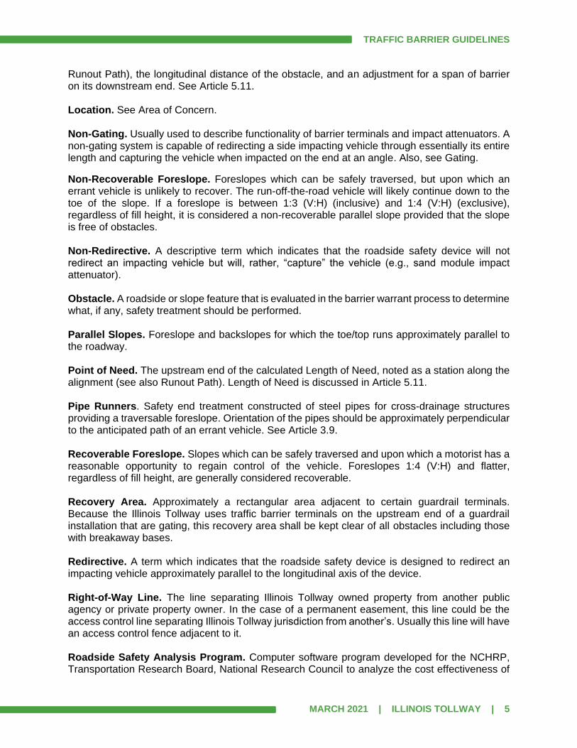
1.2 Abbreviations and Acronyms
AASHTO American Association of State Highway and Transportation Officials AASHTO GDHS AASHTO A Policy on Geometric Design of Highways and Streets AASHTO LRFD AASHTO Load and Resistance Factor Design AASHTO MASH AASHTO Manual for Assessing Safety Hardware AASHTO RDG AASHTO Roadside Design Guide ADT Average Daily Traffic AOC Area of Concern B.S. Backslope B/C Benefit to Cost Ratio BWA Barrier Warrant Analysis CCTV Closed Circuit Television CD Compact Disc C-D Collector - Distributor (Road) CLSM Controlled Low Strength Material CM Construction Manager CMA Cold Mix Asphalt CMB Cable Median Barrier DCM Design Corridor Manager DMS Dynamic Message Sign DSE Design Section Engineer EON End of Need EOP Edge of Pavement EOS Edge of Paved Shoulder EOTW Edge of Traveled Way F.S. Foreslope FHWA Federal Highway Administration, Department of Transportation GEC General Engineering Consultant

TRAFFIC BARRIER GUIDELINES
MARCH 2021 | ILLINOIS TOLLWAY | 2
G-R-E-A-T Guardrail Energy Absorbing Terminal IDOT Illinois Department of Transportation ISTHA Illinois State Toll Highway Authority (Illinois Tollway) ITS Intelligent Transportation System KCZ Curve Correction Factor L2 Lateral Offset of Barrier L3 Extent of Obstacle nearest the EOTW LA Lateral Extent of Area of Concern LC Clear Zone LON Length of Need LR Runout Length LRFD Load and Resistance Factor Design LS Shy Line Offset MGS Midwest Guardrail System MOT Maintenance of Traffic MPH or mph Miles per Hour MSE Mechanically Stabilized Embankment MVDS Microwave Vehicle Detection System MwRSF Midwest Roadside Safety Facility NAW Noise Abatement Wall NCHRP National Cooperative Highway Research Program P.C. Point of Curvature P.T. Point of Tangency PBD Performance Based Design PM Project Manager PON Point of Need ROW Right of Way RSAP Roadside Safety Analysis Program RWIS Roadway Weather Information System SE Superelevation SI Severity Index TBG Illinois Tollway Traffic Barrier Guidelines TBT Traffic Barrier Terminal TL - # NCHRP 350 or MASH Test Level (of the number specified) VEP Value Engineering Proposal WBPM Web-Based Program Management system (currently using e-Builder)
1.3 Definitions
AASHTO Manual for Assessing Safety Hardware. An update to NCHRP Report 350 that supersedes it for the purposes of evaluating new safety hardware devices. (See Section 8.0) AASHTO Roadside Design Guide. A guide that presents a synthesis of current information and operating practices related to roadside safety. It is developed and maintained by the AASHTO Subcommittee on Design, Technical Committee for Roadside Safety. Area of Concern. A rigid obstacle, slope or other roadside condition that may warrant safety treatment. May also be called “Location”.

TRAFFIC BARRIER GUIDELINES
MARCH 2021 | ILLINOIS TOLLWAY | 3
Asperity. A measurable surface irregularity in the vertical profile of a surface, within one of three categories: perpendicular, rounded, or angled surface interruption. Reference is made to NCHRP Report 554 that includes Guidelines for Aesthetic Barrier Design, which combines the relationship between different surface parameters, such as depth, width and angle. Even small depths can present a snagging potential for impacting vehicles. Backslope. The parallel sideslope created by connecting the ditch bottom, shelf behind gutter, or back of gutter, upward and outward from the roadway, to the natural ground line. Barn-Roof Foreslope. Also referred to as a Variable Foreslope, it is an embankment section that uses a recoverable foreslope (typically 1:6 (V:H)) out to the limit of the defined clear zone and then uses a steeper slope down to the ditch bottom. This steeper slope shall be recoverable, or non-recoverable, but shall not be critical. Barrier Terminals. See Traffic Barrier Terminal. Barrier Warrant Analysis. The process in which an AOC is analyzed to determine whether or not it can be either removed, relocated, the severity reduced, or shielded. The term also refers to the collective document consisting of all of the AOCs within the contract limits, which contains all of the information needed for the analyses. Chief Engineering Officer. The Chief Engineering Officer of the Illinois Tollway. Clear Zone. The clear zone is defined by the AASHTO Roadside Design Guide as “The unobstructed, traversable area provided beyond the edge of the through traveled way for the recovery of errant vehicles”. See Article 5.3 for detailed definition and application of the clear zone by the Illinois Tollway. Construction Manager. The Engineer or firm of engineers and their duly authorized employees, agents and representatives retained by the Illinois Tollway to observe The Work to determine whether or not it is being performed and constructed in compliance with the Contract. Crashworthy. A characteristic of a roadside appurtenance that has been successfully crash tested for a certain test level in accordance with a national standard such as the NCHRP Report 350, Recommended Procedures for the Safety Performance Evaluation of Highway Features, for previous installations or AASHTO MASH for any new installations. See Section 8.0. Critical Foreslope. Foreslopes steeper than 1:3 (V:H), regardless of fill height, that cannot be safely traversed by a run-off-the-road vehicle. Depending on the encroachment conditions, a vehicle on a critical foreslope may overturn. Design Review and Collaboration Platform (DRCP). Software used to electronically review, comment and dispose of comments using a live interface that allows for a more efficient and completely paperless review process. Design Section Engineer. The Engineer or firm of Engineers and their duly authorized employees, agents and representatives retained by the Illinois Tollway to prepare the Contract Plans for a Design Section.

TRAFFIC BARRIER GUIDELINES
MARCH 2021 | ILLINOIS TOLLWAY | 4
Design Speed. The traffic speed controlling design of the roadway as defined in Article 2.2 of the Illinois Tollway Roadway Design Criteria Manual. The design speed of a ramp varies and is subject to adjustment based on a speed profile. The Design Speed is further defined in Article 5.2 of this manual. Designer. The person (or consultant team) responsible for performing a design task for an Illinois Tollway project. Although this is typically the Design Section Engineer (DSE), it may also include a person (or consultant team) hired by a Contractor to perform design as part of a Value Engineering Proposal or part of a Performance Based Design. This document will use the term “Designer” which covers anyone performing design and will only use the term “DSE” when discussing tasks specific to the DSE. Downstream. The direction going with the flow of traffic. Edge of Pavement. The longitudinal joint between roadway pavement and shoulder pavement. In many locations, the outside lane of roadway pavement was built 1’ wider, or even 2’ wider than it is striped. For the purpose of barrier warrant calculations, offsets are referenced from the direction of traffic flow and measured from the edge of the traveled way. Edge of Shoulder. The edge of paved shoulder that is furthest from the edge of pavement. Edge of Traveled Way. The edge of roadway as viewed by the driver. Commonly, signified by the inside edge of a pavement marking edge line. For the purpose of barrier warrant calculations, if the lane pavement is built 1’ or 2’ (nominal) wider than the striped lane width, then the EOTW is considered to be 1’ or 2’ inside of the EOP. End of Need. For the purpose of this manual, the End of Need is the downstream point where the barrier is no longer needed. It could also be described as the point or station, of the downstream end, of the Length of Need. Foreslope. The parallel sideslope created by connecting the outside edge of shoulder (usually aggregate shoulder) or the shelf behind the gutter, downward and outward from the roadway, to the ditch bottom or natural ground line. Gating. Usually used to describe functionality of barrier terminals and impact attenuators. A gating system will allow a vehicle impacting at an angle, at or near the end of the device to pass on through – it gates; at some distance downstream from its end, it will be an effective barrier and be able to redirect an impacting vehicle. Also, see Non-Gating.
Impact Attenuator. Also called Energy Attenuator. An energy absorbing device used to shield a rigid obstacle, such as a concrete barrier, a median barrier, or a bridge pier, by gradually decelerating the vehicle to a safe stop or by redirecting the vehicle away from the obstacle. Intersecting Slopes. See Transverse Slopes. Lateral Extent of Area of Concern. The distance to the outer limit of the obstacle (see Area of Concern) from the EOTW. See Article 5.5. Length of Need. The extent of barrier required to adequately shield an obstacle (see Area of Concern) from being impacted by an errant vehicle. This includes the distance upstream of the obstacle from which an errant vehicle’s path theoretically would first encounter the barrier (see
TRAFFIC BARRIER GUIDELINES
MARCH 2021 | ILLINOIS TOLLWAY | 5
Runout Path), the longitudinal distance of the obstacle, and an adjustment for a span of barrier on its downstream end. See Article 5.11. Location. See Area of Concern. Non-Gating. Usually used to describe functionality of barrier terminals and impact attenuators. A non-gating system is capable of redirecting a side impacting vehicle through essentially its entire length and capturing the vehicle when impacted on the end at an angle. Also, see Gating.
Non-Recoverable Foreslope. Foreslopes which can be safely traversed, but upon which an errant vehicle is unlikely to recover. The run-off-the-road vehicle will likely continue down to the toe of the slope. If a foreslope is between 1:3 (V:H) (inclusive) and 1:4 (V:H) (exclusive), regardless of fill height, it is considered a non-recoverable parallel slope provided that the slope is free of obstacles. Non-Redirective. A descriptive term which indicates that the roadside safety device will not redirect an impacting vehicle but will, rather, “capture” the vehicle (e.g., sand module impact attenuator). Obstacle. A roadside or slope feature that is evaluated in the barrier warrant process to determine what, if any, safety treatment should be performed. Parallel Slopes. Foreslope and backslopes for which the toe/top runs approximately parallel to the roadway. Point of Need. The upstream end of the calculated Length of Need, noted as a station along the alignment (see also Runout Path). Length of Need is discussed in Article 5.11. Pipe Runners. Safety end treatment constructed of steel pipes for cross-drainage structures providing a traversable foreslope. Orientation of the pipes should be approximately perpendicular to the anticipated path of an errant vehicle. See Article 3.9. Recoverable Foreslope. Slopes which can be safely traversed and upon which a motorist has a reasonable opportunity to regain control of the vehicle. Foreslopes 1:4 (V:H) and flatter, regardless of fill height, are generally considered recoverable. Recovery Area. Approximately a rectangular area adjacent to certain guardrail terminals. Because the Illinois Tollway uses traffic barrier terminals on the upstream end of a guardrail installation that are gating, this recovery area shall be kept clear of all obstacles including those with breakaway bases. Redirective. A term which indicates that the roadside safety device is designed to redirect an impacting vehicle approximately parallel to the longitudinal axis of the device. Right-of-Way Line. The line separating Illinois Tollway owned property from another public agency or private property owner. In the case of a permanent easement, this line could be the access control line separating Illinois Tollway jurisdiction from another’s. Usually this line will have an access control fence adjacent to it. Roadside Safety Analysis Program. Computer software program developed for the NCHRP, Transportation Research Board, National Research Council to analyze the cost effectiveness of

TRAFFIC BARRIER GUIDELINES
MARCH 2021 | ILLINOIS TOLLWAY | 6
roadside alternatives as they relate to safety. This program is used by the Illinois Tollway in barrier warrant analyses for Level 3 warrants. Roadway. A Roadway consists of all through lanes, auxiliary lanes and shoulders in one direction of travel. Runout Length. Theoretical distance needed for a vehicle that has left the roadway to come to a stop. For barrier warrant calculations, it is measured from the upstream extent of the obstacle along the roadway to the point at which a vehicle is assumed to leave the roadway. See AASHTO RDG Table 5-10b. Runout Path. Straight line path that approximates the path an errant vehicle would take to just miss the point on the AOC that is a distance of LA from the EOTW. See Section 4.6. The runout path is the hypotenuse of the triangle whose sides are LR and LA in Figure 4.6. The intersection of the runout path and the longitudinal barrier is the PON. Severity Index. A number from zero to ten used to categorize crashes by the probability of their resulting in property damage, personal injury, or fatality, or any combination of these possible outcomes. This index is a factor used by the RSAP in its analysis. Shielded Slope. A sideslope (foreslope or backslope) that has guardrail or another barrier placed between the slope and the roadway. Shielding. The introduction of a barrier or crash cushion between the EOTW and an obstacle or area of concern to reduce the severity of impacts of errant vehicles. Shoulder Point. Point on a cross section where the slope of the aggregate shoulder (or shelf behind the gutter) meets the slope of the foreslope or backslope. (for example, uppermost point on the foreslope, and the lowest point on the backslope). Shy Line Offset. The distance from the edge of traveled way (EOTW) beyond which a roadside object will not be perceived as an obstacle by the typical driver, to the extent that the driver will change the vehicle’s placement or speed. Sideslope. A ratio used to express the steepness of a slope adjacent to the roadway. The ratio is expressed as vertical to horizontal (V:H). See Foreslope and Backslope. Test Level. A Test Level (abbreviated “TL-#“, where “#” designates the numerical test level) relates to a grouping of specified crash test conditions, such as vehicle mass, impact speed, approach angle and point of impact on a barrier. The AASHTO MASH uses six distinct test levels to describe the performance conditions whereby increasing test levels, correspond with increasing vehicle size and test speed. Test levels 1 through 3 use a small car and pickup truck as test vehicles. Test Level 1 (TL-1), speeds of less than 30 MPH, is not used on the Illinois Tollway system. TL-2 is applicable to design speeds of less than 45 MPH, TL-3 is used for design speeds of 45 MPH and greater and is tested at 62 MPH. Higher test levels retain the TL-3 performance requirements for the small car and pickup truck, but introduce larger vehicles. TL-4 includes a single unit truck (22,000 pounds), TL-5 includes a tractor/van trailer (79,300 pounds) and TL-6 includes a tractor/tanker trailer (79,300 pounds), which has a higher center of gravity. Toe of Slope. The intersection of the foreslope with the natural ground line or ditch bottom, before any rounding is applied.
TRAFFIC BARRIER GUIDELINES
MARCH 2021 | ILLINOIS TOLLWAY | 7
Top of Slope. The intersection of the backslope with the natural ground line, before any rounding is applied. Traffic Barrier Terminal. The devices or systems attached to the approach and departing end of a guardrail installation used to anchor the installation and provide tension in the rail, and in some cases transition to other types of barriers (e.g., concrete barrier (single-face and double-face barrier), bridge parapets, retaining walls, etc.). See Section 10.0. Transverse Slopes. Also called intersecting slopes. Slopes for which the toe runs approximately perpendicular to the flow of traffic on the major roadway. Transverse slopes are typically formed by intersections between the mainline and entrances, median turnarounds, or side roads. They are also formed by a bridge cone or when transitioning from a ditch section to a non-ditch section. A transverse slope facing approaching traffic is considered to have a positive grade, while a transverse slope facing away from approaching traffic is considered to have a negative grade. Negative grade transverse slopes can be also be formed by a bridge cone on the downstream side of the bridge. The ratio is expressed as vertical to horizontal (V:H). Traversable Element. Roadside feature (other than slopes, ditches, or berms), generally in an un-paved area, that can be traversed across or over by an errant vehicle without vaulting, rolling or snagging. For the element to be considered traversable, the element itself or what remains after the breakaway device is activated shall meet the requirement of Figure 3.4.1 in this document (4” projection over a 5’ chord). Traversable Elements include certain breakaway sign (see below) and light pole bases (see below); safety end treatments on culverts such as grates and pipe runners; or manhole, handholes, valves and drainage structures. For a ground-mounted sign (steel support or wood post) to be considered a Traversable Element, in addition to the above 4” projection in a 5’ chord criterion, one of the following shall also be met per AASHTO guidelines:
1. Base is located on a backslope from the shelf behind gutter or from the back of gutter
2. Base is located on a backslope from the ditch bottom where the ditch section is
considered a preferred section based on AASHTO RDG Figures 3-6 and 3-7
3. Base is located on a 1:6 (V:H) or flatter foreslope and the 1:6 slope extends from the
shoulder point to at least 4’ past the base (for multiple bases, use base that is farthest
from the roadway) [Note that the extension of the 1:6 slope should not only occur at the
sign, but the width should transition upstream a reasonable distance]
For a ground-mounted light pole base to be considered a Traversable Element, in addition to the above 4” projection in a 5’ chord criterion, it shall meet the grading requirements of Illinois Tollway Standard Drawing H1 (unshielded options only). Undefined Clear Zone. Where the sideslopes along the roadway are such that a definite clear zone distance is not determined based on AASTHO RDG Table 3-1 (foreslopes steeper than 1:4 (V:H); backslopes steeper than 1:3 (V:H)). Unshielded Slope. A sideslope (foreslope or backslope) that does not have guardrail or another barrier between the roadway and the sideslope. Because an errant vehicle would be expected on an unshielded slope, the sideslope within the clear zone limits shall be free of obstacles that are not considered Traversable Elements.
TRAFFIC BARRIER GUIDELINES
MARCH 2021 | ILLINOIS TOLLWAY | 8
Upstream. The direction going against the flow of traffic. Well Outside Clear Zone. A reasonable offset distance beyond the defined clear zone which, when applied to an obstacle’s location, would significantly reduce the probability of it being impacted by an errant vehicle. This is generally variable along the Illinois Tollway system. It is determined by the Designer, and takes several factors into account, such as ADT, number of lanes, slope configuration and severity of obstacle.
NOTE: This manual follows the traditional definitions for shall, should and may. Shall is used to mean something that is required or mandatory, while should is used to mean something that is recommended, but not mandatory and may is used to mean something that is optional and carries no requirement or recommendation.
TRAFFIC BARRIER GUIDELINES
MARCH 2021 | ILLINOIS TOLLWAY | 9
SECTION 2.0 GENERAL POLICIES Determination of cost-effective measures to reduce the severity or eliminate roadside obstacles requires the combination of the use of these guidelines, analytical evaluation and sound engineering judgement. The goal of maintaining a safe highway environment for Illinois Tollway patrons shall be at the forefront of preparing design and construction work for the Illinois Tollway. The design, construction and use of roadside barriers along the Illinois Tollway shall be in accordance with the requirements of this Manual and the current editions of the Illinois Tollway Standard Drawings, IDOT Standard Specifications and Illinois Tollway Supplemental Specifications to IDOT Standard Specifications. The barrier warrant process detailed in this Manual is based on the latest edition of the AASHTO RDG. The RSAP software has undergone a major rewrite which was finalized in late 2012. However, until further notice, the Designers shall use Version 2 of RSAP for any Level 3 Analyses. In evaluating conditions along the Illinois Tollway, the Designer shall realize that traffic barriers themselves become an obstacle that can be struck by an errant vehicle and therefore, their use shall be clearly warranted. Therefore, all reasonable alternatives to eliminate or minimize the need for barrier shall be investigated. As stated in the AASHTO RDG, Section 5.1, “the primary purpose of all roadside barriers is to reduce the probability of an errant vehicle striking a fixed object or terrain feature off the traveled way that is less forgiving than striking the barrier itself.” The BWA is ultimately the responsibility of the Designer. The Illinois Tollway will review for consistency to Illinois Tollway policies, procedures and common practice, and provide answers to questions; however, such review shall not be construed as relieving the Designer of responsibility for the BWA. Construction changes, VEPs and PBDs may have an impact on the final BWA as submitted by the DSE. In cases where changes require a revision to the final barrier warrant, the barrier warrant amendment process shall be followed and is discussed in Article 7.7. The Illinois Tollway may offer a semi-automated barrier warrant computation tool for use by the Designer. The intent of any such tool is to aid in the expedient preparation of the Barrier Warrant Analysis report. The automated tool cannot assess the suitability of a computation to any given situation or field conditions, apply engineering judgement or resolve conflicts. The Designer may or may not elect to use such a tool, however, the Designer retains sole responsibility to review and verify the accuracy, completeness and/or correctness of the Barrier Warrant Analysis report resulting from the use of any such tool.

TRAFFIC BARRIER GUIDELINES
MARCH 2021 | ILLINOIS TOLLWAY | 10
SECTION 3.0 POTENTIAL ROADSIDE OBSTACLES
3.1 General
This section discusses the most common roadside obstacles and slope features that will be encountered when performing a BWA. The Designer shall consider the following design options in the order in which they are listed when analyzing potential obstacles:
1. Remove obstacle – always the most desirable, but not always feasible
2. Relocate obstacle – when relocating an obstacle, it shall be placed either in an area that
is shielded by otherwise justified barrier or far enough from the roadway so it is unlikely
to be struck by an errant vehicle
3. Reduce impact severity
4. Shield obstacle
Future maintenance of an obstacle or a barrier shall be considered as part of the evaluation. Only existing obstacles and proposed obstacles that will remain at the end of the construction contract should be considered for inclusion in the barrier warrant report.
3.2 Gutters and Curbs
The construction of gutter and curb along Illinois Tollway mainline, plazas and ramps should be considered a method to collect runoff and/or to prevent/minimize erosion of the foreslope and not a method for shielding roadside obstacles. All gutter constructed along the Illinois Tollway mainline, Collector-Distributor (C-D) roadways and ramps shall be Gutter, Type G-3 or Gutter, Type G-2. Generally, Gutter, Type G-3 is used along the mainline and C-D roadways and Gutter, Type G-2 is used along ramps. Gutter, Type G-3 Modified and Gutter, Type G-2 Modified shall only be used in certain situations. Refer to Section 10.0 for use of gutters and gutter transitions at guardrail terminals and to the Illinois Tollway Roadway Design Criteria for more information on the use of gutters and curbs. Gutter may be constructed in conjunction with guardrail, but is not required solely because of the presence of guardrail and vice versa. Gutter, Types G-3 and G-2, are not allowed along unshielded embankment slopes steeper than 1:6 (V:H). Guardrail shall not be constructed to solely shield improperly placed gutter or curb. Guardrail used in conjunction with gutters shall be located such that the offset from the edge of paved shoulder to the face of the guardrail is in conformance with Illinois Tollway Standard Drawing B28. Curb shall not be constructed in gore areas. Existing curbs in gore areas shall be removed and replaced with asphalt shoulders, incorporating trench drains, if necessary.

TRAFFIC BARRIER GUIDELINES
MARCH 2021 | ILLINOIS TOLLWAY | 11
3.3 Embankments
The need for traffic barriers for embankment shielding is generally based upon the height and steepness of the foreslope for a fill section and shall be determined utilizing the methods outlined in Section 5.2.1 of the AASHTO RDG. Figure 5-1b of the AASHTO RDG shall be utilized to determine if barrier is warranted for all embankment conditions including foreslopes steeper than 1:3 (V:H). (Note on the use of Figure 5-1b: slope conditions that fall on the line between shielding and not shielding do not warrant shielding). All embankment slopes should be constructed in a manner that minimizes the use of barriers.
Figure 3.3 Embankment
Ditches located at the toe of embankments shall conform to the requirements of Article 3.10. See Article 5.3 for clear zone determination for barn-roof foreslopes.
3.4 Sign Supports
Ground-Mounted Sign Supports
Existing unshielded ground-mounted signs supports shall be checked to determine if they are currently Traversable Elements or can be made Traversable Elements (See Definitions in Article 1.3). Existing ground-mounted signs with breakaway bases (steel supports and wood posts) that

TRAFFIC BARRIER GUIDELINES
MARCH 2021 | ILLINOIS TOLLWAY | 12
are not Traversable Elements should either be relocated on a foundation at the proper elevation and/or be regraded to meet the requirement. Unless placed well outside the clear zone, all proposed unshielded ground-mounted sign supports shall be Traversable Elements, regardless of foundation type (steel breakaway, wood, telescoping steel). To be considered a Traversable Element, ground-mounted sign supports shall be breakaway, shall meet the 4” maximum projection as shown in Figure 3.4.1 and be located on a 1:6 or flatter foreslope. Additionally, sign supports that meet the conditions above but are located on backslopes or foreslopes that are 1:4 through 1:6, are considered traversable when the face of the support is within 24 inches of the shoulder breakpoint (intersection of the shoulder slope and the foreslope).
Figure 3.4.1 Breakaway Clearance Diagram
Existing steel breakaway sign support sizes shall be checked for conformance with the latest post sizes in the Illinois Tollway Standard Drawings. Existing wood post sign supports shall have drilled holes of the proper size and at the proper distance from the ground surface, perpendicular to the line of travel as described in the Illinois Tollway Roadway Signing and Pavement Marking Guidelines. Existing telescoping steel sign supports shall be as described in the Illinois Tollway Roadway Signing and Pavement Marking Guidelines.
Existing Overhead Sign Truss (Span)
Existing overhead sign supports located on the foreslope are usually located within the clear zone. The Designer shall evaluate whether or not it is cost-effective to replace the truss with a longer span to eliminate the need for shielding. The evaluation shall also consider whether or not the sign panels will be replaced and any other modifications to the existing truss. The side of the concrete foundation that is approximately parallel to the edge of traveled way is not considered an obstacle if it has a vertical face or a safety shape, is at least 32” above grade and approach grading is 1:10 (V:H) or flatter. The blunt end of the concrete foundation facing

TRAFFIC BARRIER GUIDELINES
MARCH 2021 | ILLINOIS TOLLWAY | 13
approaching traffic is always considered an obstacle regardless of the height. Foundations consisting of separate concrete circular columns are always considered blunt objects.
Existing Overhead Sign Truss (Cantilever and Butterfly)
Existing cantilever and butterfly sign supports are usually located within the clear zone and typically cannot be relocated far enough from the EOTW to place the foundation well outside of the clear zone while still placing the sign panel(s) at the desired location. The side of the concrete foundation that is approximately parallel to the edge of traveled way is not considered an obstacle if it has a vertical face or a safety shape, is at least 32” above grade and approach grading is 1:10 (V:H) or flatter. The blunt end of the concrete foundation facing approaching traffic is always considered an obstacle regardless of the height.
New Overhead Sign Truss (Span, Cantilever and Butterfly)
Economical overhead sign truss installations may result in the placement of sign supports and foundations within the clear zone, which results in the placement of traffic barriers to shield the foundations. However in many situations, it may be cost-effective to place overhead sign truss supports well outside of the clear zone. Because the cantilever and butterfly trusses have a maximum arm length, it may not be possible to move the foundation well outside of the clear zone and still place the sign panel(s) or DMS unit at the desired location. The side of the concrete foundation that is approximately parallel to the edge of traveled way is not considered an obstacle if it has a vertical face or a safety shape, is at least 32” above grade and approach grading is 1:10 (V:H) or flatter. The blunt end of the concrete foundation facing approaching traffic is always considered an obstacle regardless of the height. The control cabinet and any other above ground hardware required for the new sign truss shall be located such that shielding by a barrier is not required. If this cannot be accomplished, investigation should be made into locating this equipment where it will be shielded by otherwise warranted barriers.
3.5 Bridge Piers and Abutments
In general, structural elements should be placed as far from the EOTW as practical to avoid the need for shielding. Structural elements supporting the superstructure of a bridge are unique because, they need to be shielded for the safety of vehicle occupants, and also require protection from collision damage. The AASHTO LRFD Bridge Design Specification puts forth standards to address this latter case, “Protection of Structures.” Since this standard relates to structural components that support the bridge (abutments and piers), it does not apply to other nonsupport components, such as, wing walls or retaining walls.
TRAFFIC BARRIER GUIDELINES
MARCH 2021 | ILLINOIS TOLLWAY | 14
Bridge piers and non-crashworthy abutments that are within the clear zone shall be protected by a crash wall, a structurally independent TL-5 rigid concrete barrier, or as described in the Illinois Tollway Structure Design Manual. Bridge piers and abutments are further discussed in Articles 5.4 and 5.7.7 of this manual. The blunt ends of crash walls, rigid concrete barriers, or parapets are discussed in Article 3.19. Median Pier Guardrail Protection (a system of guardrail wrapped around median piers) is no longer used by the Illinois Tollway. Instead use one of the following options:
1. New bridge piers located in a grass median shall be constructed with a crash wall as
shown in the Illinois Tollway Structure Design Manual
2. Existing bridge piers located in a grass median shall be shielded as shown in the Illinois
Tollway Structure Design Manual
3. Shielding of new or existing sign truss foundations in a grass median shall be as
determined by a BWA performed by the Designer
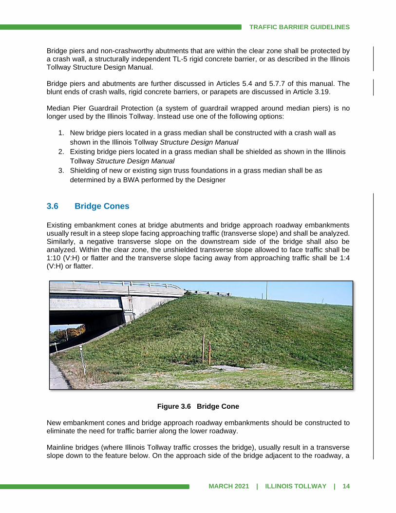
3.6 Bridge Cones
Existing embankment cones at bridge abutments and bridge approach roadway embankments usually result in a steep slope facing approaching traffic (transverse slope) and shall be analyzed. Similarly, a negative transverse slope on the downstream side of the bridge shall also be analyzed. Within the clear zone, the unshielded transverse slope allowed to face traffic shall be 1:10 (V:H) or flatter and the transverse slope facing away from approaching traffic shall be 1:4 (V:H) or flatter.
Figure 3.6 Bridge Cone New embankment cones and bridge approach roadway embankments should be constructed to eliminate the need for traffic barrier along the lower roadway. Mainline bridges (where Illinois Tollway traffic crosses the bridge), usually result in a transverse slope down to the feature below. On the approach side of the bridge adjacent to the roadway, a
TRAFFIC BARRIER GUIDELINES
MARCH 2021 | ILLINOIS TOLLWAY | 15
negative transverse slope is likely to be encountered. When within the clear zone, this transverse slope, and any positive transverse slope on the opposing side that is accessible to traffic, shall be analyzed as an AOC.
3.7 Retaining Wall Drop-Offs
In general, retaining wall drop-offs should be placed as far from the edge of roadway as possible. Normally retaining walls are necessary when there is a lack of available right-of-way, however, retaining wall drop-offs present a more severe risk to run-off-the-road vehicles than embankments. The height of the drop-off, proximity to the roadway, foreslope gradient, design speed, traffic volumes, location on the outside on curved roadways, availability of a recovery area and other features may be factors in determining the severity of a drop-off obstacle. The Designer shall use engineering judgement to determine the relative severity of drop-off, however, all retaining wall drop-offs greater than three feet in height shall be considered an Obstacle for the purpose of the barrier warrant analysis. Retaining wall drop-offs within the clear zone require a Level 2 analysis. When the drop-off is just beyond the clear zone, a barrier shall be considered based on engineering judgement and/or a Level 3 analysis. When shielding is determined to be required, a reinforced concrete TL-5 barrier shall be used.
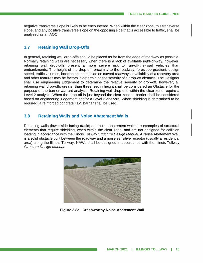
3.8 Retaining Walls and Noise Abatement Walls
Retaining walls (lower side facing traffic) and noise abatement walls are examples of structural elements that require shielding, when within the clear zone, and are not designed for collision loading in accordance with the Illinois Tollway Structure Design Manual. A Noise Abatement Wall is a solid obstacle built between the roadway and a noise sensitive receptor (usually a residential area) along the Illinois Tollway. NAWs shall be designed in accordance with the Illinois Tollway Structure Design Manual.
Figure 3.8a Crashworthy Noise Abatement Wall
TRAFFIC BARRIER GUIDELINES
MARCH 2021 | ILLINOIS TOLLWAY | 16
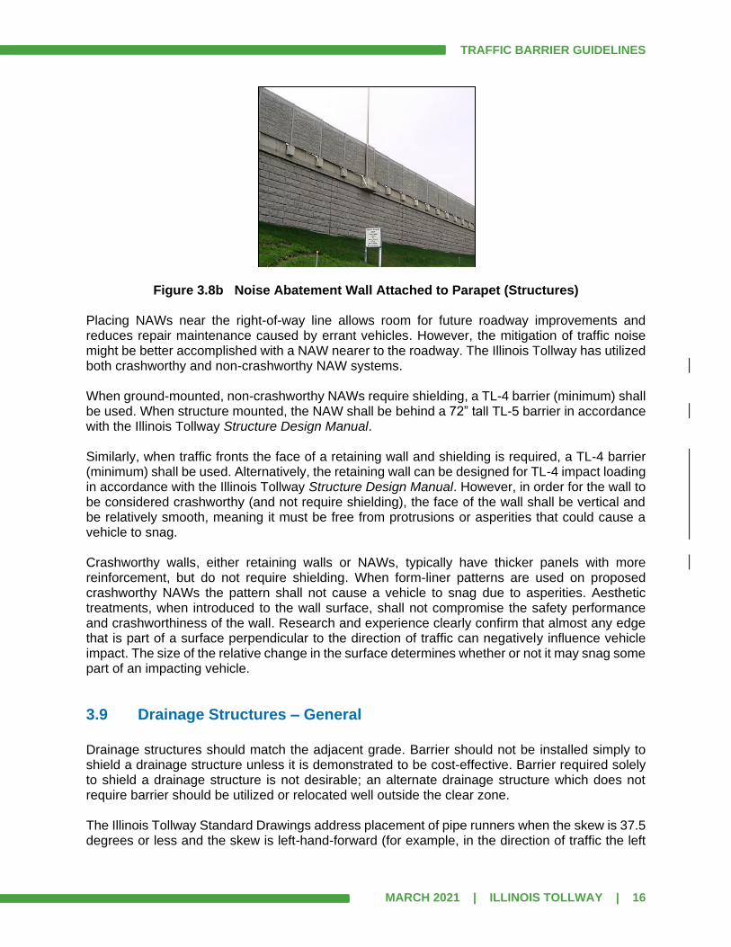
Figure 3.8b Noise Abatement Wall Attached to Parapet (Structures)
Placing NAWs near the right-of-way line allows room for future roadway improvements and reduces repair maintenance caused by errant vehicles. However, the mitigation of traffic noise might be better accomplished with a NAW nearer to the roadway. The Illinois Tollway has utilized both crashworthy and non-crashworthy NAW systems. When ground-mounted, non-crashworthy NAWs require shielding, a TL-4 barrier (minimum) shall be used. When structure mounted, the NAW shall be behind a 72” tall TL-5 barrier in accordance with the Illinois Tollway Structure Design Manual. Similarly, when traffic fronts the face of a retaining wall and shielding is required, a TL-4 barrier (minimum) shall be used. Alternatively, the retaining wall can be designed for TL-4 impact loading in accordance with the Illinois Tollway Structure Design Manual. However, in order for the wall to be considered crashworthy (and not require shielding), the face of the wall shall be vertical and be relatively smooth, meaning it must be free from protrusions or asperities that could cause a vehicle to snag. Crashworthy walls, either retaining walls or NAWs, typically have thicker panels with more reinforcement, but do not require shielding. When form-liner patterns are used on proposed crashworthy NAWs the pattern shall not cause a vehicle to snag due to asperities. Aesthetic treatments, when introduced to the wall surface, shall not compromise the safety performance and crashworthiness of the wall. Research and experience clearly confirm that almost any edge that is part of a surface perpendicular to the direction of traffic can negatively influence vehicle impact. The size of the relative change in the surface determines whether or not it may snag some part of an impacting vehicle.
3.9 Drainage Structures – General
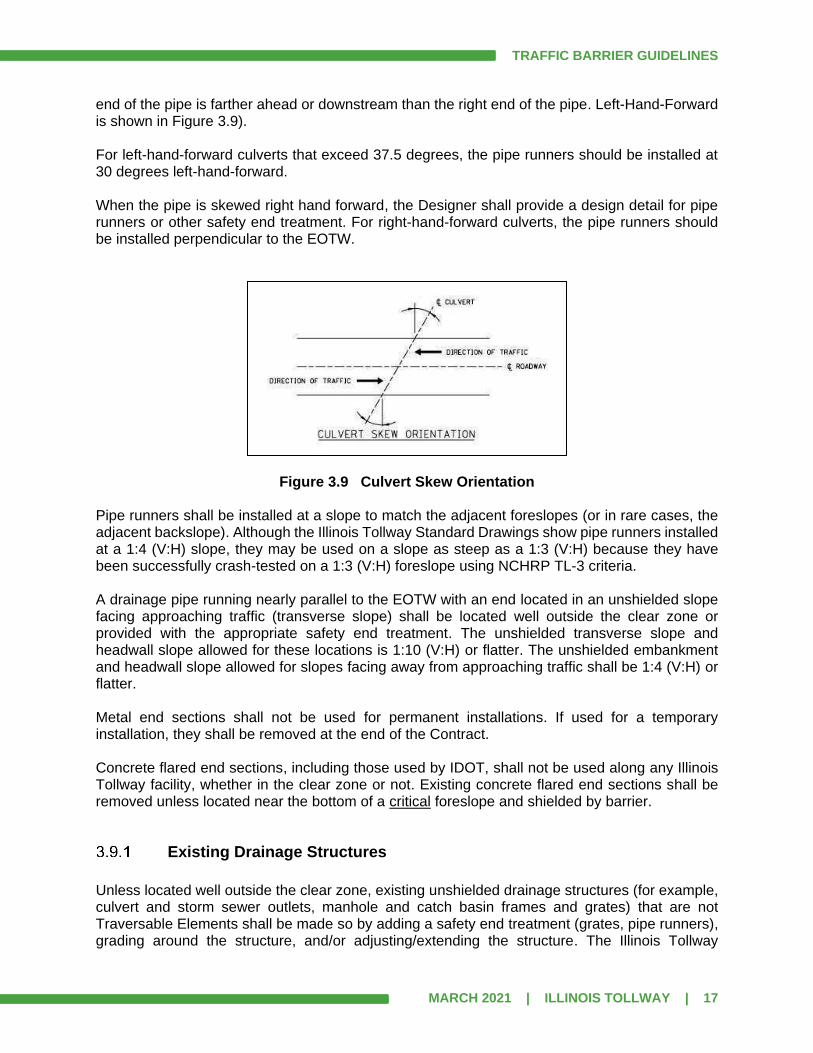
Drainage structures should match the adjacent grade. Barrier should not be installed simply to shield a drainage structure unless it is demonstrated to be cost-effective. Barrier required solely to shield a drainage structure is not desirable; an alternate drainage structure which does not require barrier should be utilized or relocated well outside the clear zone. The Illinois Tollway Standard Drawings address placement of pipe runners when the skew is 37.5 degrees or less and the skew is left-hand-forward (for example, in the direction of traffic the left
TRAFFIC BARRIER GUIDELINES
MARCH 2021 | ILLINOIS TOLLWAY | 17
end of the pipe is farther ahead or downstream than the right end of the pipe. Left-Hand-Forward is shown in Figure 3.9). For left-hand-forward culverts that exceed 37.5 degrees, the pipe runners should be installed at 30 degrees left-hand-forward. When the pipe is skewed right hand forward, the Designer shall provide a design detail for pipe runners or other safety end treatment. For right-hand-forward culverts, the pipe runners should be installed perpendicular to the EOTW.
Figure 3.9 Culvert Skew Orientation Pipe runners shall be installed at a slope to match the adjacent foreslopes (or in rare cases, the adjacent backslope). Although the Illinois Tollway Standard Drawings show pipe runners installed at a 1:4 (V:H) slope, they may be used on a slope as steep as a 1:3 (V:H) because they have been successfully crash-tested on a 1:3 (V:H) foreslope using NCHRP TL-3 criteria. A drainage pipe running nearly parallel to the EOTW with an end located in an unshielded slope facing approaching traffic (transverse slope) shall be located well outside the clear zone or provided with the appropriate safety end treatment. The unshielded transverse slope and headwall slope allowed for these locations is 1:10 (V:H) or flatter. The unshielded embankment and headwall slope allowed for slopes facing away from approaching traffic shall be 1:4 (V:H) or flatter. Metal end sections shall not be used for permanent installations. If used for a temporary installation, they shall be removed at the end of the Contract. Concrete flared end sections, including those used by IDOT, shall not be used along any Illinois Tollway facility, whether in the clear zone or not. Existing concrete flared end sections shall be removed unless located near the bottom of a critical foreslope and shielded by barrier.
Existing Drainage Structures
Unless located well outside the clear zone, existing unshielded drainage structures (for example, culvert and storm sewer outlets, manhole and catch basin frames and grates) that are not Traversable Elements shall be made so by adding a safety end treatment (grates, pipe runners), grading around the structure, and/or adjusting/extending the structure. The Illinois Tollway

TRAFFIC BARRIER GUIDELINES
MARCH 2021 | ILLINOIS TOLLWAY | 18
Drainage Design Manual includes a flowchart to assist the Designer in choosing the appropriate end treatment based on pipe size, sideslope and outlet velocity. In sideslopes that are mowed it is desirable to have the structures flush with the ground.
Proposed Drainage Structures
Proposed culvert and storm sewer outlets shall be constructed so that the exposed top slope of the structure including wingwalls and any safety end treatment (pipe runners, grates) matches the adjacent sideslope. The resulting foreslope between shoulder point and the top edge of the structure should be the same as the foreslope upstream and downstream of the structure. Safety end treatments shall be constructed to the same slope as the adjacent cross section so that errant vehicles are presented with a relatively uniform slope without dips or bumps. When necessary, a plan detail shall be developed (using the Illinois Tollway Standard Drawings as a guide) to match the existing or proposed slopes, especially for skewed pipes. In sideslopes that will be mowed, the Designer should choose drainage structures with safety grates, when necessary, for ease of maintenance. If possible, proposed culverts and drainage structures should be oriented perpendicular to the flow of traffic. Skewed pipes should not exceed 30 degrees from perpendicular. The Illinois Tollway Drainage Design Manual includes a flowchart to assist the Designer in choosing the appropriate end treatment based on pipe size, sideslope and outlet velocity. Unless located well outside the clear zone, proposed manhole and catch basin frames and grates shall be Traversable Elements. In sideslopes that are mowed it is desirable to have the structures flush with the ground.
3.10 Ditches
New or reconstructed ditches in unshielded areas should be constructed as specified in the Illinois Tollway Roadway Design Criteria, and desirably to the preferred sections discussed in Section 3.2.4 of the AASHTO RDG. The standard ditch has a 4’ minimum flat bottom, as discussed in the Illinois Tollway Roadway Design Criteria, Figure 2.6.8. However, barrier shall not be placed solely to shield a ditch whose bottom width is less than 4’. Unshielded ditches with less than a 4’ flat bottom width should be modified to provide at least the standard width of 4’. Ditches that do not fall within the preferred channel section on AASHTO RDG Figures 3-6 and 3-7 are less desirable and should not be used where high-angle encroachments are expected. However, ditch channel sections that do not meet these AASHTO RDG Figures’ requirements are not necessarily considered obstacles by themselves. On rehabilitation projects where evaluation of the existing sideslopes is within the scope of work, the existing ditches should be modified to conform to the Illinois Tollway criteria. Enclosing the drainage system by filling in the ditch and placing runoff in a pipe is another alternative that could be cost effective in certain situations and should be evaluated.
TRAFFIC BARRIER GUIDELINES
MARCH 2021 | ILLINOIS TOLLWAY | 19
A ditch check at the toe of an unshielded foreslope shall be constructed with a 1:10 (V:H) or flatter slope facing approaching traffic and 1:4 (V:H) or flatter slope facing away from approaching traffic. See Article 5.7.14 for information on how to analyze a ditch.
3.11 Riprap
Good design practice dictates that riprap not be used unless located well outside the clear zone. Even small size riprap, if not hand-placed, could be considered non-traversable and an obstacle to an errant vehicle. Barrier shall not be placed solely to shield non-traversable riprap. If riprap is justified, it shall be located behind otherwise warranted barrier. Riprap shall not be used around guardrail or terminal posts. The use of riprap in ditch bottoms and on sideslopes needs to be justified because of safety and maintenance concerns. Refer to the Illinois Tollway Drainage Design Manual and the Illinois Tollway Erosion and Sediment Control, Landscape Design Criteria for more information on the proper use of riprap.
3.12 Roadway Lighting (Ground-Mounted)
Ground-Mounted light poles are typically furnished or retrofitted with breakaway bases or supports, even if installed behind guardrail. Refer to Illinois Tollway Guidelines for Roadway Illumination, Article 7.7, Lighting Standards, for installations where breakaway devices are required and where they should not be used. Poles with breakaway devices shall meet the criteria illustrated in Figure 3.4.1, and shall be Traversable Elements (See Definitions, Article 1.3) Light poles (existing and proposed) shall be located outside of the recovery area for a TBT Type T1 (Special) or Type T1-A (Special), shown in Figure 10.3.1c and Figure 10.3.2b, respectively. When an existing light pole is located within the recovery area of the terminal, desirably the light pole shall be relocated outside of the recovery area. If it is not feasible to relocate the light pole, then the guardrail shall be extended or shifted to meet the requirements. Barrier should not be installed solely to shield light poles.
Existing Installations
When an existing light pole with a non-breakaway base/pole is encountered where a breakaway device is required per Illinois Tollway Guidelines for Roadway Illumination, Article 7.7, Lighting Standards, it should be removed and replaced with a current standard light pole and foundation. An unshielded pole that is not a Traversable Element shall not remain without modification. Many times minor regrading will address the issue.

TRAFFIC BARRIER GUIDELINES
MARCH 2021 | ILLINOIS TOLLWAY | 20
An existing pole to remain behind proposed guardrail shall meet the minimum barrier clearance distance for the type of guardrail used (See Article 9.2). Unless located well outside the clear zone, an existing handhole or similar item shall be made a Traversable Element. If minor grading cannot be done to meet the requirements, the obstacle shall be adjusted or relocated. In areas that will be mowed, it is good practice to keep all obstacles flush with the ground. Existing foundations, or other above-ground obstacles shall be relocated, unless located behind otherwise warranted barrier.
New Installations
Light poles shall be located outside of the recovery area for a TBT Type T1 (Special) or Type T1-A (Special). All light pole foundations (including breakaway devices) shall meet the minimum barrier clearance for the type of guardrail used. (See Article 9.2) Lighting controllers and transformers should be located such that shielding by a barrier is not required. If this cannot be accomplished, investigation should be made into locating this equipment where it will be shielded by otherwise warranted barriers. Proposed handholes, foundations, or other permanent obstacles shall meet the definition of a Traversable Element unless shielded by otherwise warranted barrier or located well outside the clear zone. Even when located behind barrier it is good practice to keep all obstacles flush with the ground in all areas that will be mowed. Installing a CCTV or audit camera to a light pole makes the assembly a non-breakaway device. See Article 3.13.
3.13 Communication Systems and ITS Devices
CCTV Cameras, MVDS and RWIS installations are considered non-breakaway devices. Where possible, locate these non-breakaway installations in areas which are inaccessible to errant vehicles or where they will be shielded by otherwise warranted barrier. Because maintenance of these devices is a consideration, these installations shall also be coordinated with the Illinois Tollway ITS Group.
3.14 Utility Poles
Telephone, electric, communication and other types of utility poles are typically non-breakaway installations and should be relocated well outside the clear zone or relocated underground if possible.
TRAFFIC BARRIER GUIDELINES
MARCH 2021 | ILLINOIS TOLLWAY | 21
The Designer shall coordinate the final locations through the Illinois Tollway Utility Coordinator and utility company.
3.15 Trees
Normal construction practices require the removal of most trees within the right-of-way of proposed roadways. Ornamental or other significant trees may be left in place if located well outside the clear zone. New trees shall only be planted well outside the clear zone.
3.16 Bodies of Water
Permanent bodies of water greater than 2’ in depth and within the clear zone require shielding. Limits of the obstacle begin at location where 2’ depth is exceeded. Areas subject to periodic inundation and bodies of water less than 2’ in depth (normal water elevation), which are located within or near the clear zone, should be analyzed based on an engineering judgement decision considering location, depth of water, frequency of inundation and likelihood of encroachment. Particular attention should be given to areas intended for use as storm water detention sites, where design high water elevations may meet the criteria for shielding. The Designer shall consider roadside safety, frequency of high water and duration of high water level in all storm water detention site designs and should attempt to locate such detention basins well outside the clear zone. Avoid placing bodies of water on the outside of a curve or near the toe of a non-recoverable foreslope. Existing bodies of water, accessible by errant vehicles, regardless of distance from the EOTW, shall be investigated based on encroachment history and engineering judgement. When an analysis is justified, a Level 3 analysis shall be performed. Additional consideration should be given to locating bodies of water, outside of curves adjacent to ramps since the geometry of curving ramps may increase the likelihood of lane departures.
3.17 Rock Cuts
Roadway construction in cut areas may expose rough rock faces which pose a snagging potential to errant vehicles. The Designer shall also consider the potential for falling rock. See Discussion in Example 3-I in AASHTO RDG Chapter 3.
3.18 Right-of-Way Line
Because the Illinois Tollway has no control over what an adjacent property owner will do on their property, these areas need to be considered when identifying obstacles. The ROW fence at any offset is generally not considered an obstacle. See Article 5.7.21 for guidance on analyzing a ROW line obstacle.
TRAFFIC BARRIER GUIDELINES
MARCH 2021 | ILLINOIS TOLLWAY | 22
3.19 Blunt Ends
The blunt end of a concrete barrier (single-face or double-face), parapet (on bridge or retaining wall), or wall (retaining wall with no parapet or the first column of a crash-worthy NAW) that is facing approaching traffic is considered an obstacle and shall be shielded when not located well outside the clear zone. This is typically done with guardrail or an impact attenuator. The back side of a concrete barrier is a potential obstacle to adjacent roadways. The back side, whether F-Shape, constant slope or vertical, is not considered an obstacle if it is at least 32” above grade, the approach grade is 1:10 (V:H) or flatter and the angle relative to the adjacent roadway and the shy line offset of the adjacent roadway meet the values in AASHTO RDG Table 5-9.

TRAFFIC BARRIER GUIDELINES
MARCH 2021 | ILLINOIS TOLLWAY | 23
SECTION 4.0 BARRIER WARRANT ANALYSIS STEP-BY-STEP PROCEDURE
The evaluation of potential roadside obstacles shall be performed in an organized manner that allows an orderly process of identification and implementation of corrective measures. The recommended methodology for evaluating roadside obstacles is as follows:
4.1 Identify Potential Obstacles.
Reasonable care shall be taken to identify all potential roadside obstacles (See Section 3.0 for Potential Roadside Obstacles) before the clear zone is determined. The limits for consideration shall be measured from the EOTW to the larger of the following two distances: 60’ from the EOTW or 10’ beyond the toe of slope. The potential obstacles could be existing or proposed items. The Designer shall use site surveys of existing conditions and/or analyses of proposed designs in an effort to identify all relevant data and information regarding site conditions as they pertain to roadside safety. Record drawings may be utilized at this step to identify items that exist that may not necessarily be visible during a field review. The Designer shall make every attempt to design and place proposed obstacles so that they are either a Traversable Element or not accessible to an errant vehicle. It is the Designer’s prerogative to analyze very severe obstacles (bodies of water, large drop-offs, etc.) regardless of distance beyond the EOTW based on engineering judgement. When AOCs are on the outside of the initial curve of an exit ramp, a sharp ramp curve, or loop ramp, the Designer shall use engineering judgement and the severity of the obstacle to determine if it shall be included in a Level 2 or 3 analysis, even though it may not normally be considered an obstacle that warrants shielding. It is not necessary to identify obstacles that are greater than 400’ downstream of the upstream end of a blunt end of a continuously running parapet, retaining wall, or other TL-5 barrier, because any obstacles behind the parapet would naturally be shielded by the parapet. However, the Designer shall analyze all obstacles downstream of the downstream end of said parapet/retaining wall. When analyzing obstacles greater than 400’ downstream of the upstream end of a blunt end of a continuously running TL-4 barrier or crashworthy noise abatement wall, the AOC shall be identified and listed on the Level 0 Table. Obstacles that are or will be mounted to the top of a barrier or parapet should not be included.
4.2 Name Obstacles.
Name all potential obstacles (Areas of Concern (AOC) or Location) by the direction of the adjacent traffic (NB, SB, EB, WB) followed by a unique number. For example, NB obstacles would be AOC NB-1, AOC NB-2, AOC NB-3, etc. Numbers/Names shall not be changed once they are assigned. AOCs along ramps should use the direction of the mainline that the ramp is adjacent to on the ramp designation. For example, Ramp A AOCs could be named NA-1, NA-2, NA-3 or RA-1, RA-2, RA-3, etc.
TRAFFIC BARRIER GUIDELINES
MARCH 2021 | ILLINOIS TOLLWAY | 24
Although each AOC shall have a unique number designation, common AOCs that have the same status and disposition may be given a distinct “group” designation, such as G-01, G-02, G-03 etc. (alternately GE-01 for Existing and GP-01 for Proposed). All AOCs with a group designation, shall all have identical descriptions (all existing light poles with the same breakaway base, all existing ground-mounted signs, or all existing handholes) and have the same disposition (removed/remain/traversable). Group AOCs shall be listed on a single line on their respective Level 0 or Level 1 table. Group AOC labels shall not be used for Level 1 AOCs that need to be modified, or altered to be made traversable, however they may be used for Level 1 AOCs that are already traversable and have identical descriptions. Group AOC designations shall not be used for any AOC that is part of a Level 2 or Level 3 analysis. When including record barrier warrant analyses from a previous contract, it would be appropriate to assign a new AOC number, based on the project numbering scheme, followed by the prefix “Rec” and the Record AOC number in brackets. Thus “NB-57[Rec N13A]” would designate current AOC NB-57 and record AOC number N13A. Normally, AOCs of a de minimis nature are not assigned an AOC number. Unless special circumstances exist, underdrain outlets, milepost signs, delineator posts, signs mounted on light poles or on top of concrete barriers and routine traffic signs that are to be removed as part of the project, do not need to be assigned an AOC number nor included on a Level 0 or 1 Table.
4.3 Prepare/Present Exhibit.
Before any analysis is performed, the DSE shall prepare a plan exhibit showing all AOCs and present it to the Illinois Tollway for review/discussion at a meeting. The general goals of the meeting are to:
1. Provide an overview of the project limits, scope of work and any omissions 2. Summarize the overall project schedule 3. Discuss potential AOCs and BWA methodology 4. Present unique project issues 5. Identify locations that are good candidates to be included in the preliminary submittal
The Designer shall bring a copy of the template/form they intend to use for barrier warrants for review at the meeting. The Designer shall also bring a sample Table of Contents to show how the barrier warrant document will be packaged and presented. For rehabilitation contracts, the meeting and presentation of the exhibit should occur approximately 2 weeks before the Concept Plan submittal. This allows the meeting minutes to be included in the Concept Plan submittal. No other barrier warrant exhibits are required for the Concept Plan submittal. For reconstruction contracts, the meeting and presentation of the exhibit should occur one to two weeks before the Preliminary Plan submittal, possibly using the QA/QC set for the presentation.
For reconstruction or rehabilitation projects the exhibit should include: 1. Proposed edges of pavement, shoulder, gutter
TRAFFIC BARRIER GUIDELINES
MARCH 2021 | ILLINOIS TOLLWAY | 25
2. Existing guardrail, impact attenuators and CMB
3. Proposed/existing retaining walls, NAWs, barriers, parapets, abutments, piers
4. Proposed/existing sign truss and cantilever sign foundations
5. Proposed/existing drainage structures in gutters and in sideslopes
6. Existing bodies of water
7. ITS devices
8. Other potential issues/obstacles
9. All AOCs labeled
10. Stationing
11. North arrow
12. Bar scale
13. Plan Exhibit shall be presented at 1”=50’ (for rehabilitation projects) or 1”=100’ (for
reconstruction) true scale on topo or aerial background (color aerial preferred)(36” roll
plot preferred in manageable lengths, but full-size cut sheets could be used as well or
projected from digital images)
14. Some preliminary cross sections should be available to properly discuss slope features
(or a plan showing contours)
15. Photos of existing guardrail installations and existing obstacles (required for
rehabilitation contracts and optional for reconstruction)
4.4 Archived Barrier Warrants
The Designer should request a copy of all previous barrier warrant analyses for the project location from the Illinois Tollway.
4.5 Analysis of Areas of Concern
Each AOC that requires a Level 1, 2 or 3 analysis shall be investigated. When AOCs are in close proximity to each other, it may be possible to combine them or to determine the controlling AOC. See Article 5.6.3 for further discussion of combining or determining the controlling AOC.
When an AOC is adjacent to the mainline and an auxiliary lane or ramp lane, then the AOC shall be analyzed from the mainline and from the auxiliary or ramp lane separately. See Section 6.0 for discussion of AOC summarization and presentation.
4.6 Area of Concern – Analysis Procedure
For each Level 2 or Level 3 AOC, the following steps shall be followed:
Establish EOTW
This may or may not be the same as the EOP. See Article 1.3 and Article 5.1.

TRAFFIC BARRIER GUIDELINES
MARCH 2021 | ILLINOIS TOLLWAY | 26
Design Speed
Determine design speed at upstream end of AOC. For all mainline locations, the design speed is either 60 or 70 mph per Illinois Tollway Roadway Design Criteria. When analyzing from the C-D roadway use the design speed for the C-D, which is typically 10 mph less than the mainline. For ramps, auxiliary lanes, or any other speed change situation, the Designer shall use the design speed as calculated by a speed profile. See Article 5.2.
Design ADT
ADT for design year in the direction being analyzed. When analyzing the AOC from the ramp, use ramp ADT and when analyzing from the auxiliary lane use the volume in the auxiliary lane. Usually the ADT volumes are supplied by the Illinois Tollway.
Runout Length
Based on design speed at upstream end of AOC, determine LR using AASHTO RDG Table 5-10b. Note that LR should be interpolated for 35, 45, 55 and 65 mph. See Figure 4.6 for basic terms used in analysis, which is also AASHTO RDG Figure 5-39.
Shy Line Offset
Determine LS using AASHTO RDG Table 5-7.
Foreslope/Backslope
Develop proposed cross sections (every 100’ or less), use as-built cross sections from record drawings, or perform supplemental survey to determine foreslope and backslope values. Obstacles, such as sign trusses, should be shown on the nearest cross section or a section cut at the AOC.
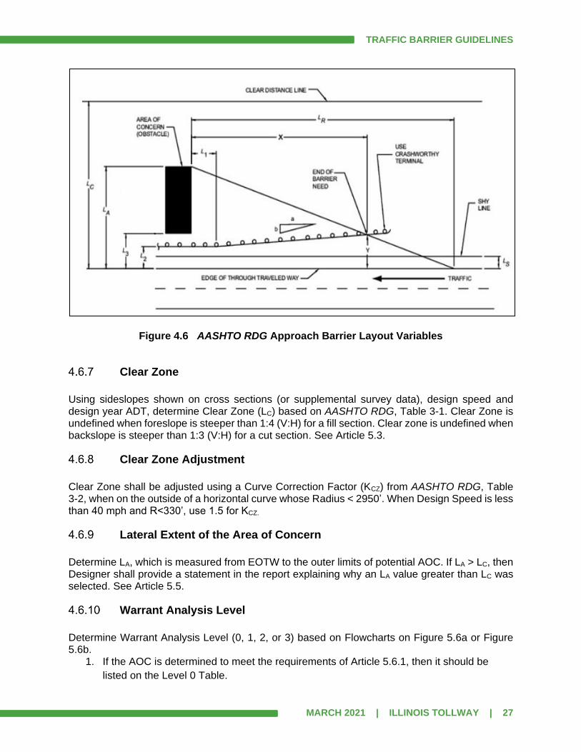
TRAFFIC BARRIER GUIDELINES
MARCH 2021 | ILLINOIS TOLLWAY | 27
Figure 4.6 AASHTO RDG Approach Barrier Layout Variables
Clear Zone
Using sideslopes shown on cross sections (or supplemental survey data), design speed and design year ADT, determine Clear Zone (LC) based on AASHTO RDG, Table 3-1. Clear Zone is undefined when foreslope is steeper than 1:4 (V:H) for a fill section. Clear zone is undefined when backslope is steeper than 1:3 (V:H) for a cut section. See Article 5.3.
Clear Zone Adjustment
Clear Zone shall be adjusted using a Curve Correction Factor (KCZ) from AASHTO RDG, Table 3-2, when on the outside of a horizontal curve whose Radius < 2950’. When Design Speed is less than 40 mph and R<330’, use 1.5 for KCZ.
Lateral Extent of the Area of Concern
Determine LA, which is measured from EOTW to the outer limits of potential AOC. If LA > LC, then Designer shall provide a statement in the report explaining why an LA value greater than LC was selected. See Article 5.5.
Warrant Analysis Level
Determine Warrant Analysis Level (0, 1, 2, or 3) based on Flowcharts on Figure 5.6a or Figure 5.6b.
1. If the AOC is determined to meet the requirements of Article 5.6.1, then it should be
listed on the Level 0 Table.

TRAFFIC BARRIER GUIDELINES
MARCH 2021 | ILLINOIS TOLLWAY | 28
2. If the AOC is determined to meet the requirements of Article 5.6.2, then it should be
listed on the Level 1 Table.
3. If the AOC is determined to have multiple feasible alternatives which meets the
requirements of Article 5.6.4 then a Level 3 analysis shall be performed. Continue with
step 4.6.11 (Lateral Offset of Barrier) below. Evaluate alternatives using RSAP.
4. If the AOC is determined to meet the requirements of Article 5.6.3, then a Level 2
analysis shall be performed. Continue with following steps to determine length of barrier
for different alternatives.
Barrier Test Level
The relative risk of occupant injury from striking an obstacle may determine the type of barrier required to shield the obstacle. Obstacles that are considered more severe, warrant a more substantial barrier. The Illinois Tollway uses guardrail, a Test Level-3 (TL-3) barrier, to shield most roadside AOCs. More severe AOCs are shielded with a rigid barrier, such as a concrete barrier that is either TL-4 or TL-5. See the definitions of the various Test Levels in Article 1.3. Also, Section 3 and Section 5 discuss various AOCs and any barrier Test Level that may be required. The Test Level of a barrier should not be confused with the BWA, Analysis Level. The “Analysis Level” describes how the obstacle is analyzed and the “Test Level” refers to the relative strength and stiffness of the barrier. When analyzing AOCs that require different Test Level barriers, the higher Test Level should be analyzed first, before the lower test levels. This is because a higher Test Level barrier can be substituted for a lower Test Level barrier, but a lower Test Level barrier cannot be substituted for a higher Test Level barrier. Additionally, the higher Test Level barriers (TL-4 and TL-5 concrete barriers) will always create a blunt end AOC when it faces approaching traffic.
Lateral Offset of Barrier
Determine L2 (based on whether gutter is present or not) measured from EOTW. See Article 5.9.
Upstream End of Guardrail
1. If it appears that the upstream end of the guardrail installation will be free-standing
(when not attached to a structure), then the upstream end of the barrier needs to be
determined using the following:
A. Calculate Y (always equals L2 + 0.69’ for calculation purposes when Design Speed is
more than 40 mph) measured from EOTW. See Article 5.10.
B. Determine dimension X, which is portion of LON that is upstream of AOC by:
1) Using formula: X = (LA – Y) / (LA/LR) for AOCs on tangent or on the inside of a
horizontal curve. See Article 5.11.1.
2) Using graphical method to scale X when upstream end of AOC or any portion of
LR is located on the outside of a horizontal curve. See Article 5.11.2.
3) Using graphical method to scale X when L2 is variable width, shoulder width is
varying or outside lane is tapering. See Article 5.11.2.
4) Using graphical method to scale X when guardrail installation is installed on a
taper. Taper rate shall not exceed values in AASHTO RDG Table 5-9. Note that
TRAFFIC BARRIER GUIDELINES
MARCH 2021 | ILLINOIS TOLLWAY | 29
tapered installations are typically only used on the approaching side of toll
plazas.
C. Calculate PON Station. PON is X distance upstream from the upstream end of AOC.
D. If analyzing the length of existing barrier, see Article 5.15.
2. If upstream end of guardrail installation will be connected to a structure (such as a bridge
parapet, bridge pier or crash wall, or retaining wall), then determine proper guardrail
terminal. See Section 10.0.
Downstream End of Barrier
Determine if downstream end will be free-standing or attached to structure. See Article 5.13.
1. Free-standing –
A. Determine if the downstream end will be concrete barrier or guardrail. If guardrail,
determine appropriate terminal. See Section 10.0.
B. Determine the downstream barrier adjustment needed from the downstream end of
the obstacle. This is based on one of the two conditions presented in Article 5.14.
Note that this may be a negative value if Condition 2 is used. This is determined
whether the barrier is concrete or guardrail.
2. Attached to structure –
A. Determine if concrete shoulder barrier transition is needed.
B. Determine if the downstream end will be concrete barrier or guardrail. If guardrail is
used, then determine terminal type based on the presence of gutter. See Section
10.0.
Length of Need
Calculate the LON using the formula: LON = X + Length of AOC + Downstream barrier adjustment.
Upstream End of Concrete Barrier
If concrete barrier is used to shield all or a portion of an AOC, then determine end of concrete barrier (See Article 5.12). Even if the concrete barrier completely shields the AOC, the blunt end needs to be shielded.
Barrier Limits Determination
Determine portion of LON that is not shielded by terminals or concrete barrier (or parapet) (See Article 5.14).
1. Length of Guardrail – LON minus the contribution from the terminals (if any) minus the
length of concrete barrier (if any). Guardrail needs to be rounded up to the nearest 12.5’
length (unless both the downstream and upstream ends are attached to structure). If
guardrail run is free-standing, then verify that minimum length requirement is met (See
Article 5.16).
TRAFFIC BARRIER GUIDELINES
MARCH 2021 | ILLINOIS TOLLWAY | 30
2. For upstream guardrail terminal, verify that recovery area is clear of obstacles. If not
clear, then obstacle should be relocated. If absolutely necessary, adjust guardrail length
to provide a clear recovery area.
3. Determine station limits for each type of guardrail (Types A, B and C determined based
on barrier clearance distance; See Article 9.2) and for each terminal.
Barrier Limits Check
If upstream guardrail terminal location was not adjusted, then Designer shall verify that the terminal end is the proper distance from the PON.
Barrier Obstacle
Determine if proposed concrete barrier, guardrail and/or terminals could be considered a potential AOC for an adjacent roadway. The backside of guardrail or a terminal shall not be accessible to traffic. If the backside of concrete barrier is accessible to traffic, then the taper rate shall not exceed the values from AASHTO RDG Table 5-9. Barriers should not be installed to shield other barrier; other options should be considered.
Compare Existing Length to Proposed
For rehabilitation projects where an existing AOC was shielded and will remain, compare existing length of shielding to proposed length. If significantly different (>50’), provide possible reasons why proposed length varies from existing. Note that an existing system using a previous standard can only be extended using the current standard guardrail if certain conditions are met. See Articles 9.8 and 9.8.1.
Prepare Warrant Text and Exhibits
See Section 6.0 for format and presentation requirements.

TRAFFIC BARRIER GUIDELINES
MARCH 2021 | ILLINOIS TOLLWAY | 31
SECTION 5.0 ANALYSIS PROCEDURE – DETAILS
5.1 Edge of Traveled Way vs. Edge of Pavement
The edge of traveled way (EOTW) and edge of pavement (EOP) are defined in Article 1.3. For the BWA, all lateral measurements shall be from the EOTW. The offset direction (Right or Left) is based on the direction of the flow of traffic.
5.2 Design Speeds
In utilizing the AASHTO RDG, the term “operating speed”, as used therein, shall be interpreted to mean the same as “design speed” as used herein. Design speeds to be used in the BWA along the Illinois Tollway shall be as follows:
Location Design Speed
Mainline Roadway, C-D Roadway and Directional Ramps at a System Interchange
As specified in the Illinois Tollway Roadway Design Criteria
Ramps at a Service Interchange (Diamond, Outer and Loop) **
New Construction As specified in the Illinois Tollway Roadway Design Criteria for first curve after exiting the Illinois Tollway for an exit ramp and for the last curve on an entrance ramp. For other curves along the ramp, design speed shall be determined according to a developed design speed profile. Existing Facilities As determined by using current superelevation charts, find resulting design speed for each curve by inputting the existing SE rate and radius of curve
Speed Transition Areas (Ramp Terminals, Toll Plazas and Intersection Approaches) **
According to a design speed profile.
Crossroads ** In accordance with IDOT’s Design Policies; or documented requests or policy of Agency having jurisdiction over the crossroad, wherever IDOT’s policies do not apply. The source of the design speed criteria used in analyses along crossroads shall be stated in the analysis. The Agency having jurisdiction over the crossroad shall review and approve all analyses.
** Speed profile shall be developed utilizing acceleration and deceleration charts from the AASHTO Green Book. An example is shown in Article 6.11.1.
TRAFFIC BARRIER GUIDELINES
MARCH 2021 | ILLINOIS TOLLWAY | 32
5.3 Clear Zone
The clear zone width is dependent upon traffic volume, speed, roadside sideslopes and roadway curvature. It is the Illinois Tollway’s policy to provide a clear zone as free of obstacles as possible. In performing Warrant Analyses, the clear zone width shall be determined following the procedure outlined in Chapter 3 of the AASHTO RDG. Using design speed, design year ADT and sideslope, the highest value within the range from AASHTO RDG Table 3-1 shall be used. The Illinois Tollway does not limit the clear zone width to 30’ nor does the Illinois Tollway assign a typical or constant clear zone width to a Contract (for example, the clear zone will likely vary longitudinally depending upon roadside conditions). When sideslopes are too steep the clear zone may be undefined, but it is never zero. In AASHTO RDG Table 3-1, use the “1V:6H or flatter” columns for 1:6 or flatter slopes, the “1V:5H to 1V:4H” columns for slopes steeper than 1:6 and 1:4 or flatter, the “1V:3H” column for slopes steeper than 1:4. Foreslopes steeper than 1:4 (V:H) and backslopes steeper than 1:3 (V:H) have undefined clear zones. The Designer should also be aware that the clear zone may extend beyond the Illinois Tollway ROW. The values for “backslopes” in Table 3-1 only apply when no foreslope exists. If the existing embankment was constructed using a barn-roof foreslope, determining the clear zone could take several steps. In some instances, the clear zone used in the past to determine the limit of the recoverable slope is less than the clear zone that is used today. The first step is to find the clear zone from Table 3-1 based on the flatter of the two foreslopes.
1. If the clear zone falls within the flatter foreslope, then use the clear zone based on the flatter slope.
2. If the clear zone falls onto the steeper of the two foreslopes, then the clear zone should be based on the steeper foreslope value. If the steeper foreslope is recoverable, then the clear zone is defined and should be determined from Table 3-1. If the steeper foreslope is non-recoverable or critical, then the clear zone is undefined and should not be adjusted.
The Illinois Tollway does not use the clear runout area as defined in the AASHTO RDG 3.2.1 to adjust the clear zone. See Articles 5.5 and 5.7.1 for a discussion on how to analyze an embankment AOC. If located on the outside of a horizontal curve, where the radius is less than 2950’, the clear zone shall be corrected based on AASHTO RDG Table 3-2, using the highest value in the range from AASHTO RDG Table 3-1 multiplied by the factor from Table 3-2. For speeds less than 40 mph, use the factors given for 40 mph. Clear zone determination shall be properly documented as herein specified. The clear zone determination is based on proposed (or existing) cross-sections and/or contours. The roadside configuration upstream of the AOC for a distance approximately equivalent to the
TRAFFIC BARRIER GUIDELINES
MARCH 2021 | ILLINOIS TOLLWAY | 33
required runout length, LR, plus 100’ shall be investigated. As many cross sections as are required to determine the clear zone limits should be utilized and their scale plots included in the analysis. The clear zone for auxiliary or ramp lanes shall be based on design speed and traffic volume in that lane. Clear zone shall be determined within LR and along entire length of the AOC. There may be occurrences where a potential AOC is outside of the mainline clear zone but inside the auxiliary lane or ramp clear zone. Each AOC has to be analyzed separately for each clear zone. All designs requiring the construction or installation of roadside objects, structures, or slope features shall consider their location with respect to the traveled way. Every effort shall be made to either eliminate potential obstacles or locate them well outside of the clear zone. It should be noted that the clear zone criteria is based on limited research and that the ability of an errant vehicle to safely traverse the roadside and stay within the clear zone is dependent on several factors, such as the encroachment angle, configuration and steepness of slopes, slope physical condition and surface friction coefficient. By locating obstacles outside the clear zone their probability of impact is significantly reduced, but not eliminated. Therefore, the Designer shall not consider the clear zone limit as a line that an errant vehicle cannot cross. Because not all vehicles can recover within the clear zone, engineering judgement should be used in locating these obstacles at a reasonable distance outside the clear zone. In fact, striking a proposed obstacle that is located just beyond the clear zone could still be more severe than striking a roadside barrier designed to shield the obstacle. Similarly, when existing obstacles fall just outside the clear zone, consideration should be given to their removal or modification. This applies specifically to headwalls and other drainage structures as well as sign supports, especially when they are located in the foreslope, near the ditch bottom, or near other structures which are to be modified or removed.
5.4 Protection of Bridge Structures
Bridge abutments and piers, within the clear zone, are required by the Illinois Tollway Structural Design Manual and the AASHTO LRFD to either meet certain structural requirements or be protected by an independent concrete barrier from collision damage. To meet this requirement coordination with the structural designer may be necessary to determine which of the following courses to pursue. “Protection” of Structures, as discussed in this section, should not be confused with “shielding” the structure from an errant vehicle to reduce the risk to the vehicle occupants. Bridge wing walls, retaining walls, MSE walls in front of pile supported abutments and noise abatement walls are examples of structural elements that do not support a bridge superstructure, and therefore do not require protection under these Protection of Structures provisions. Shielding requirements for these types of nonsupport structural elements are discussed separately, in Article 3.8. When the face of a pier or abutment is within the clear zone it shall be investigated for Protection of Structures in accordance with the AASHTO LRFD. When an abutment is backed by soil (soil/aggregate is in continuous contact with the back face), then the abutment is considered to have adequate capacity to resist collision loads and therefore Protection of Structure measures are not required. When a pier is constructed or modified with a crash wall and the crash wall meets the requirement of the Illinois Tollway SDM, then the pier is considered to have adequate

TRAFFIC BARRIER GUIDELINES
MARCH 2021 | ILLINOIS TOLLWAY | 34
capacity to resist collision loads and therefore Protection of Structure measures are not required. The crash wall shall be a minimum of 3' thick, 60" minimum height above grade at all points along the crash wall and be at least 30 square feet in area, along every horizontal plane from the top of footing to 60" above grade. Piers and abutments not meeting the conditions above shall address Protection of Structures by one of the following options:
1. Where the design choice is to provide structural resistance substructure components
shall be specifically designed for vehicle collision forces in accordance with the Illinois Tollway Structure Design Manual.
2. When the design choice is to redirect the collision load, a structurally independent TL-5 concrete barrier shall be used. The concrete barrier shall extend across the face of the abutment or pier, plus an additional 60 feet on the upstream end. The concrete barrier would normally be placed at the edge of shoulder; however, the height of barrier will depend on the offset from the face of the structure. See Article 5.7.7 for additional criteria for the TL-5 barrier.
This Article provides a flowchart (Figure 5.4) to help determine how Protection of Structures for abutments and piers are addressed. The designer should perform this exercise before proceeding to flowcharts (Figures 5.6a and 5.6b). The upstream blunt end of a crash wall or concrete barrier shall be analyzed as an AOC. When conditions exist that make the above protection of structures requirements impractical, the Designer shall recommend a solution through the design deviation process.
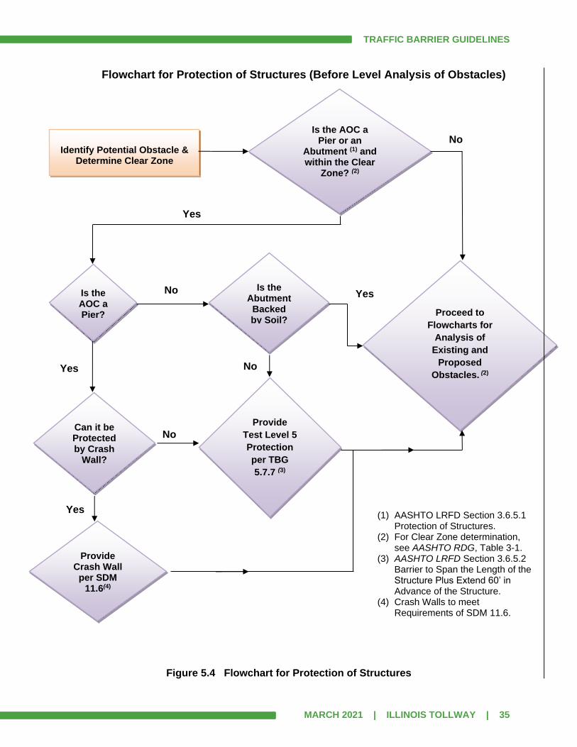
TRAFFIC BARRIER GUIDELINES
MARCH 2021 | ILLINOIS TOLLWAY | 35
Flowchart for Protection of Structures (Before Level Analysis of Obstacles)
Figure 5.4 Flowchart for Protection of Structures
Is the AOC a Pier or an
Abutment (1) and within the Clear
Zone? (2)
Identify Potential Obstacle &
Determine Clear Zone
Is the AOC a Pier?
Provide
Test Level 5
Protection
per TBG
5.7.7 (3)
Proceed to
Flowcharts for
Analysis of
Existing and
Proposed
Obstacles. (2)
(1) AASHTO LRFD Section 3.6.5.1 Protection of Structures.
(2) For Clear Zone determination, see AASHTO RDG, Table 3-1.
(3) AASHTO LRFD Section 3.6.5.2 Barrier to Span the Length of the Structure Plus Extend 60’ in Advance of the Structure.
(4) Crash Walls to meet Requirements of SDM 11.6.
No
No
Yes
Yes
Is the Abutment
Backed by Soil?
Can it be Protected by Crash
Wall?
Provide Crash Wall
per SDM 11.6(4)
No
Yes
No
Yes

TRAFFIC BARRIER GUIDELINES
MARCH 2021 | ILLINOIS TOLLWAY | 36
5.5 Lateral Extent of the Area of Concern
The Lateral Extent of the Area of Concern, LA, is measured from EOTW to the outer limits of the potential AOC. LA is usually less than or equal to LC. However, there are two situations where LA could exceed LC. The first one occurs if the nearside of an AOC is within the clear zone, but is wide enough to extend outside the clear zone. Depending on the obstacle’s severity, it may be prudent to use a value for LA that extends to the far side of the AOC. The second situation involves a very severe obstacle that is located completely outside of the clear zone. In this case, the Designer may choose to use a value for LA that is greater than LC. Whenever LA > LC, the Designer shall provide a statement in the report explaining why shielding is recommended for a location that is outside of the clear zone. The outer limit of a parallel slope obstacle is based on the clear zone upstream of the obstacle. If the clear zone is defined within 100’ upstream of the obstacle, then use the defined clear zone for LA. If the clear zone is undefined within 100’ upstream of the obstacle, then use the toe of the slope obstacle as the value for LA. The outer limit of a transverse slope obstacle is based on the clear zone upstream of the obstacle. If the clear zone is defined within 100’ upstream of the obstacle, then use the defined clear zone for LA. If the clear zone is undefined within 100’ upstream of the obstacle, then use Table 5.8.1 for LA.
5.6 Warrant Analysis Level
This Article provides flowcharts (Figures 5.6a and 5.6b) to help determine analysis level, presents the definitions of each Analysis Level, and then discusses the Analysis Level that is appropriate for each of the common roadside obstacles.

TRAFFIC BARRIER GUIDELINES
MARCH 2021 | ILLINOIS TOLLWAY | 37
Flowchart for Analysis of Existing Obstacles
Figure 5.6a Flowchart for Analysis of Existing Obstacles
Is Clear Zone
Defined? (1)
Identify Potential Obstacle &
Determine Clear Zone
Is AOC well outside Clear
Zone? (2)
Traversable
Element?
Is AOC in
Clear Zone?
Easily made into
Traversable Element? (5)
Any Feasible
Alternatives?
Level 2 Analysis
Level 0
Table
Traversable
Element?
Level 1
Table
Level 3:
Compare
Options (4)
Modify – Note
in Level 1
Table
Level 3:
Compare
Options (6)
(1) See AASHTO RDG, Table 3-1. (2) Variable based on roadway type,
ADT and usage. (3) See Article 5.8.1. (4) Compare do nothing, shielding,
make it a traversable element, relocate, provide new safety end treatment, etc.
(5) Minor regrading, addition of safety end treatment for drainage structure without modifying structure, replacing non-breakaway sign posts with breakaway, etc.
(6) Compare shielding, relocation, new safety end treatment, flatten sideslope, etc.
No
No
No
No
No
No
No
No
Yes
Yes
Yes
Yes
Yes
Yes
Yes
Yes
Does AOC’s
offset to near
edge (L3) exceed
values in Table
5.8.1? (3)

TRAFFIC BARRIER GUIDELINES
MARCH 2021 | ILLINOIS TOLLWAY | 38
Flowchart for Analysis of Proposed Obstacles
Figure 5.6b Flowchart for Analysis of Proposed Obstacles
Is Clear Zone
Defined? (1)
Identify Potential Obstacle &
Determine Clear Zone
Is AOC well outside Clear
Zone? (2)
Traversable
Element?
Any Feasible
Alternatives?
Is AOC in Clear Zone?
Level 0
Table
Traversable
Element?
Level 1
Table
Any Feasible Alternatives?
Level 3: Compare
Shielded vs. Unshielded
Level 2 Analysis
(1) See AASHTO RDG, Table 3-1. (2) Variable based on roadway type, ADT and usage. (3) See Article 5.8.1.
No
No
No
No
No
Yes
Yes
s Yes
Yes
Yes
Yes
No
Yes
No
Does AOC’s offset
to near edge (L3) exceed values in
Table 5.8.1? (3)
Yes
No
Level 3: See Articles
in TBG for
Alternatives
TRAFFIC BARRIER GUIDELINES
MARCH 2021 | ILLINOIS TOLLWAY | 39
Level 0 Analysis
Potential AOCs not analyzed with a Level 1, 2, or 3 Analysis, shall be included in a Level 0 Table. See Article 6.11.3 for sample table. This table should include all potential AOCs that were initially identified in the process but were determined to be well outside of the clear zone and therefore no analysis is required. Existing AOCs that are to be removed or relocated to well beyond the clear zone as part of the work, shall be listed on the Level 0 table. Trees (or groups of trees) and other items that will be removed in the contract should also be included in the Level 0 Table. Note that it is not necessary to include all removal items in a reconstruction contract. For a Level 0 AOC, the Designer shall, as a minimum, show the AOC on the Location Plan and provide cross sections (or contours) for at least 300’ upstream of the obstacle so that the clear zone value can be verified.
Level 1 Analysis
A Level 1 Analysis shall be performed for all existing AOCs that are Traversable Elements (See Article 1.3 Definitions) or can easily be made Traversable Elements, and for all proposed AOCs that are Traversable Elements, such as:
1. Existing ground-mounted signs, and existing drainage items
2. Existing ground-mounted light poles and electrical handholes
3. Proposed ground-mounted signs with breakaway bases
4. Proposed ground-mounted light poles with approved breakaway devices
5. Proposed drainage items (culvert and pipe ends between 12” and 84” in vertical
opening)
6. Other flush with grade, underground structures, such as catch basins, handholes or
manholes
Upgrades or repairs for existing items shall also be shown in the Level 1 Table. See Article 6.11.4 for a sample Level 1 Table. Proposed installations should be designed and constructed to meet current safety requirements and Illinois Tollway Standard Drawings and shall be shown in the same table as the existing items. Proposed items shall show what safety treatment will be used on each item. For example, the table should include the nominal slope and orientation for a sloped headwall.
Level 2 Analysis
Shielding is required for a Level 2 Analysis and the barrier LON should be determined. A typical analysis shall include treatment type (guardrail or barrier), length and type of terminals. See Articles 6.11.5, 6.11.6 and 6.11.7 for sample exhibits of a Level 2 Analysis.
TRAFFIC BARRIER GUIDELINES
MARCH 2021 | ILLINOIS TOLLWAY | 40
This analysis is performed for:
1. EXISTING/PROPOSED OBSTACLES when there are no feasible alternatives for
eliminating, or reducing the impact severity of the obstacle.
2. PROPOSED OBSTACLES for an alternative in a Level 3 Analysis. The length of barrier
and type of terminals has to be determined for each alternative that involves shielding of
the obstacle.
An obstacle that requires shielding by barrier or an impact attenuator is considered a Level 2 Obstacle. Shielding for obstacles that require higher barrier test levels, take precedence over shielding for obstacles that require lower barrier test levels. Thus, when performing Level 2 analyses on multiple nearby obstacles, begin by determining the limits of the highest barrier Test Level. In situations where a barrier designed for one obstacle overlaps that of another, the higher Test Level barrier limits would govern. Hierarchically descend from TL-5 shielding limits to TL-4 shielding limits and finally to TL-3 shielding limits. In certain situations, it is possible for obstacles to be shielded by barrier that is required for another obstacle. When this occurs, it is not always necessary to perform a complete analysis for those obstacles that are clearly shielded by the barrier. The analysis for the controlling AOC (if one exists) should include a list of other AOCs that are also being shielded. When an obstacle that normally requires a level 2 analysis is obviously shielded by a barrier that has no analysis, then the obstacle should be shown in the Level 0 Table. Generally, each AOC shall be analyzed separately, but when AOCs are in close proximity to each other, it may be possible to combine them or determine the Controlling AOC. Combining of AOCs is only allowed in the following cases: (1) when the AOCs are generally at the same station, but with different offsets; (2) when an obstacle is located in the midst of a slope AOC; (3) when it is possible to determine the Controlling AOC and it can be shown graphically that other AOCs are shielded by the barrier of the Controlling AOC. When analyzing groups of AOCs, there may be a different Controlling AOC for the upstream and downstream ends of the barrier. In case (1), it is clear that the AOC further from the roadway will result in the longer LON. For case (2) it is clear that the slope AOC will control the LON. With case (3), it may be necessary to determine the runout line for most or several of the AOCs to determine the controlling PON on the upstream end and possibly several (considering the overlap condition, Fig. 5.14) on the downstream end.
Level 3 Analysis (Cost-Effective Analysis)
Elimination of all obstacles would provide the safest condition for motorists, but that is not usually practical. When the obstacle cannot be eliminated, but there are feasible alternatives to reduce its severity, a Cost-Effective Analysis (or a Level 3 Analysis) shall be performed using the RSAP computer program in accordance with the procedures outlined in Article 5.8 in this document and Article 2.2 in the AASHTO RDG. In evaluating alternatives, the do-nothing approach (alternative that leaves existing condition in place) should also be considered, but only if it is an acceptable alternative. The RSAP program is used to compare two or more alternatives and considers initial

TRAFFIC BARRIER GUIDELINES
MARCH 2021 | ILLINOIS TOLLWAY | 41
construction costs, maintenance costs and predicted accident costs to determine a Benefit/Cost ratio for each alternative as compared to the other alternatives. In any cost-effective analysis, a considerable amount of engineering judgement is required to fully utilize the methods outlined in the AASHTO RDG. Strict application of the principles and examples provided in the AASHTO RDG is not always possible. A roadside condition may be more desirable under one set of circumstances, but may not under another. Therefore, the critical first step that shall be taken is to define and/or identify the nature, the components and the limits of the condition, and only then should the design process move forward to the determination of corrective strategies and cost-effective analyses. When considering alternative measures, the cost-effectiveness of the alternative selected shall be clear and decisive. When the cost-effective advantage between alternatives is marginal or when the total cost of each alternative is relatively low, the alternative that provides the safest conditions should be selected. The Benefit/Cost Analysis procedure is a tool to aid in decision making, which estimates accident frequencies, compares costs of alternatives and provides documentation. It does not establish needs, does not always provide a definitive answer and is not a replacement for good design practice. See Article 5.8 for RSAP Guidance.
5.7 Obstacle Analysis
The following are specific requirements for many of the roadside obstacles that could be encountered along the Illinois Tollway.
Embankments
An embankment obstacle typically requires a Level 3 Analysis. A Benefit/Cost analysis shall be performed to determine if flattening of the existing foreslopes is cost-effective. Existing foreslopes that are flattened to eliminate the need for guardrail shall conform to Illinois Tollway Roadway Design Criteria wherever possible. However, if flattening the foreslope would result in ROW acquisition, which is not practical or feasible based on the project scope, then the embankment should be analyzed as a Level 2 Analysis. Other items adjacent to the embankment that may prevent flattening of the foreslope include but are not limited to: floodplain, wetlands, waterways and detention/retention basins. Proposed embankment configurations should follow the Illinois Tollway’s Roadway Design Criteria. When an embankment obstacle is not analyzed as a Level 3, the report shall include a statement addressing why it was not done.
TRAFFIC BARRIER GUIDELINES
MARCH 2021 | ILLINOIS TOLLWAY | 42
Existing Ground-Mounted Sign Supports
Existing ground-mounted sign supports that are Traversable Elements or can easily be made Traversable Elements shall be addressed in a Level 1 Table. Existing ground-mounted sign supports located within the clear zone that are not Traversable Elements require a Level 3 Analysis which evaluates the following alternatives as a minimum: (1) base condition – existing support remains with shielding; (2) sign is removed and replaced at a location, which places the support just outside of the clear zone and does not require shielding; (3) sign is removed and replaced at a location which places the support well outside the clear zone and does not require shielding. If relocation is not feasible, then the existing sign support shall be shielded and Level 2 Analysis performed. Existing ground-mounted sign supports located just outside the defined clear zone that are not Traversable Elements require a Level 3 Analysis which evaluates the following alternatives as a minimum: (1) base condition – existing support remains with no shielding; (2) existing support remains with shielding; (3) sign is removed and replaced at a location which places the support well outside the defined clear zone, and does not require shielding. If relocation is not feasible, then Alternative (3) would not be included in the analysis. Existing ground-mounted sign supports located on the foreslope when the clear zone is undefined that are not Traversable Elements, require a Level 3 Analysis which evaluates the following alternatives as a minimum: (1) base condition – existing support remains with no shielding provided that the offset in Table 5.8.1 is met; (2) existing support remains with shielding; (3) sign is removed and replaced at a location which places the support well outside the offsets shown in Table 5.8.1, and does not require shielding. If relocation is not feasible, then Alternative (3) would not be included in the analysis. Existing ground-mounted sign supports that are not Traversable Elements and are shielded by an otherwise warranted barrier may be included in the Level 1 Table, but shall be listed in the BWA of the controlling element. Minimum barrier clearance distance shall be provided behind guardrail.
Proposed Ground-Mounted Sign Supports
All proposed sign supports that can be defined as Traversable Elements shall be addressed in the Level 1 Table. All proposed sign supports that can be placed well outside of the clear zone shall be noted in the Level 0 Table. If above cannot be met, then the Designer shall perform a Level 3 Analysis to determine the most cost-effective design for all new ground-mounted sign installations. The alternatives at minimum to evaluate shall include: (1) base condition – sign offset at the minimum requirement per Illinois Tollway Standard Drawing F9 for a shielded slope; (2) location which places support outside defined clear zone with no shielding or if clear zone is undefined places support such that the criteria in Table 5.8.1 is met; (3) location which places support well outside the clear zone (or well outside the offsets shown in Table 5.8.1, if clear zone is undefined) with no shielding. For all alternatives, the sign supports shall be analyzed as rigid objects in RSAP.
TRAFFIC BARRIER GUIDELINES
MARCH 2021 | ILLINOIS TOLLWAY | 43
The Designer shall attempt to place sign supports that are not Traversable Elements where they will be shielded by guardrail that is warranted for another obstacle or will be located well outside of the clear zone.
Existing Overhead Sign Truss (Span)
Existing overhead sign supports located within the clear zone require a Level 3 Analysis which evaluates the following alternatives as a minimum: (1) base condition – existing support remains with shielding; (2) sign truss is removed and replaced with a longer span length which places foundation just outside of the clear zone and does not require shielding; (3) sign truss is removed and replaced with a longer span length which places foundation well outside the clear zone and does not require shielding. If a longer truss is not feasible, then the existing foundation shall be shielded and Level 2 Analysis performed.
Existing overhead sign supports located just outside the defined clear zone require a Level 3 Analysis which evaluates the following alternatives as a minimum: (1) base condition – existing support remains with no shielding; (2) existing support remains with shielding; (3) sign truss is removed and replaced with a longer span length which places the foundation well outside the defined clear zone, and does not require shielding. If a longer truss is not feasible, then Alternative (3) would not be included in the analysis. Existing overhead sign supports located on the foreslope when the clear zone is undefined, require a Level 3 Analysis which evaluates the following alternatives as a minimum: (1) base condition – existing support remains with no shielding provided that the offset in Table 5.8.1 is met; (2) existing support remains with shielding; (3) sign truss is removed and replaced with a longer span length which places the foundation well outside the offsets shown in Table 5.8.1, and does not require shielding. If a longer truss is not feasible, then Alternative (3) would not be included in the analysis. When an existing overhead sign truss foundation is not analyzed as a Level 3, the report shall include a statement addressing why it was not done. Previously, existing sign truss foundations in a grass median were typically shielded with Median Pier Protection. As this type of shielding is no longer used by the Illinois Tollway, existing installations of this type should be removed. The need for and type of shielding of an existing sign truss foundation in a grass median shall be determined by a Level 3 Analysis.
Existing Overhead Sign Truss (Cantilever)
Existing cantilever sign supports are usually located within the clear zone and generally cannot be relocated far enough from the EOTW to place the foundation well outside of the clear zone. However, if a longer arm for the cantilever is feasible, the Designer should perform a Level 3 Analysis which evaluates the following alternatives as a minimum: (1) base condition – existing support remains with shielding; (2) sign truss is removed and replaced with a longer arm length which places foundation just outside the clear zone and does not require shielding; (3) sign truss is removed and replaced with a longer arm length which places foundation well outside the clear zone and does not require shielding. If a longer arm is not feasible, then the existing foundation shall be shielded and Level 2 Analysis performed.
TRAFFIC BARRIER GUIDELINES
MARCH 2021 | ILLINOIS TOLLWAY | 44
Existing cantilever sign supports located just outside the defined clear zone require a Level 3 Analysis which evaluates the following alternatives as a minimum: (1) base condition – existing support remains with no shielding; (2) existing support remains with shielding; (3) sign truss is removed and replaced with a longer arm length which places the foundation well outside the defined clear zone, and does not require shielding. If a longer arm is not feasible, then Alternative (3) would not be included in the analysis. Existing cantilever sign supports located on the foreslope when the clear zone is undefined, require a Level 3 Analysis which evaluates the following alternatives as a minimum: (1) base condition – existing support remains with no shielding provided that the offset in Table 5.8.1 is met; (2) existing support remains with shielding; (3) sign truss is removed and replaced with a longer arm length which places the foundation well outside the offsets shown in Table 5.8.1, and does not require shielding. If a longer arm is not feasible, then Alternative (3) would not be included in the analysis. Because of the significant cost difference per foot of truss, it may be more economical to build a span sign truss instead of a cantilever sign truss. Therefore, the Designer should evaluate replacing the existing cantilever sign truss with a span sign truss as a possible 4th alternative. When an existing cantilever sign truss foundation is not analyzed as a Level 3, the report shall include a statement addressing why it was not done.
New Overhead Sign Truss (Span, Cantilever and Butterfly)
The Designer shall perform a Level 3 Analysis to determine the most cost-effective design for all new overhead sign installations. The alternatives at minimum to evaluate shall include: (1) base condition – shortest span or arm with shielding; (2) span or arm length which places foundation outside defined clear zone with no shielding or if clear zone is undefined places foundation such that the criteria in Table 5.8.1 is met; (3) longer span or arm which places foundation well outside the clear zone or well outside the offsets shown in Table 5.8.1 with no shielding. Because it may be more economical to install a span type instead of a cantilever type, the Level 3 Analysis should compare both types. Cantilever and Butterfly Sign Trusses, in many cases, will only require a Level 2 Analysis due to the limited arm length available. When a proposed sign truss foundation is not analyzed as a Level 3, the report shall include a statement addressing why it was not done. The need for and type of shielding of a new or existing sign truss foundation in a grass median shall be determined by a Level 3 Analysis. Proposed control cabinets or any other required hardware mounted on the ground shall be shielded by otherwise warranted barrier or located well outside the clear zone, preferably on the backslope or near the ROW fence. If this is not possible, the Designer shall perform a Level 3 Analysis to evaluate alternatives.
TRAFFIC BARRIER GUIDELINES
MARCH 2021 | ILLINOIS TOLLWAY | 45
Bridge Piers and Abutments
As discussed in Chapter 3, the analysis of piers and abutments is a two-part process. The first part is investigating the need to “Protect” the structure from collision damage. The second part is to “Shield” an errant vehicle from the structure, reducing the risk of injury to the vehicle occupants. The AASHTO LRFD Bridge Design Specifications require abutments and piers within the clear zone, either to meet certain structural requirements (thus no additional barriers are needed) or be protected with an independent TL-5 barrier. Since the limits of the higher test level barriers need to be determined before the lower ones, the following cases will discuss first establishing the TL-5 barrier limits, then any TL-4 barrier limits and finally the TL-3 (guardrail) needs.
1. Existing Bridge Piers to Remain
When the existing pier is well beyond the clear zone, structural protection and shielding are not required. When shielding is required based on a Level 2 or Level 3 analysis, the pier shall have a crash wall built around it in accordance with the Illinois Tollway SDM Article 11.6.2. A pier with an existing crash wall shall meet the requirements of the SDM or be modified to meet the requirements of the SDM. Crash wall modifications are shown on Illinois Tollway base sheets M-BRG-507 and M-BRG-508. A pier with a proper crash wall is considered to have adequate capacity to resist collision loads, therefore no additional Protection of Structures measure is required.
A. Pier in Open Median
When the pier is within an open (grass) median between opposing traffic lanes, both ends of the crash wall shall be fitted with a Concrete Median Barrier Transition, Type V (See Standard C14) and each blunt end, facing approaching traffic, shall be shielded with an impact attenuator.
B. Pier in Closed Median
When the pier is located between opposing traffic lanes, both ends of the crash wall shall be fitted with a Concrete Median Barrier Transition, Type V-DF (see Standard C13) and connected to the adjacent concrete median barrier. If the pier is not located between opposing traffic lanes (adjacent to a ramp or C-D roadway), then, at a minimum, the upstream end of the crash wall shall be fitted with a Concrete Median Barrier Transition, Type V-DF (see Standard C13) and connected to the adjacent concrete median barrier.
C. Pier along Right Shoulder or Not Between Traffic Lanes
Install a Concrete Shoulder Barrier Transition, Type V-SF (see Standard C4) at the upstream end of the crash wall. The remaining portion of the Length of Need upstream of the crash wall, shall be constructed as a TL-4 single face concrete barrier. The upstream blunt end of the single face concrete barrier shall be shielded with guardrail or an impact attenuator.

TRAFFIC BARRIER GUIDELINES
MARCH 2021 | ILLINOIS TOLLWAY | 46
If the pier is of such configuration that a crash wall cannot feasibly be installed, then the pier (or portion of the pier within the clear zone) shall be protected by a TL-5 single face concrete barrier, normally located at the edge of shoulder. 1) When the top edge of the traffic face of the barrier is less than 3.25’ from the face
of the pier, then the TL-5 barrier shall be a minimum of 54” tall (see Standard C17). The barrier shall be placed across the entire face of the pier plus an additional 60’ on the upstream end.
2) When the top edge of the traffic face of the barrier is equal to or greater than
3.25’ from the face of the pier, then the TL-5 barrier shall be a minimum of 44” tall (see Standards C15 or C16). The barrier shall be placed across the entire face of the pier plus an additional 60’ on the upstream end.
The remaining portion of the Length of Need, upstream of the TL-5 barrier, shall be constructed as a (TL-4 minimum) single face concrete barrier. If the 54” TL-5 single face concrete barrier is used, a Concrete Shoulder Barrier Height Transition, Single Face, Type SF-54 (see Standard C18) is required immediately upstream of the 54” barrier (whether it is needed for the length of need, or not). The upstream blunt end of the concrete barrier shall be shielded with guardrail or an impact attenuator.
2. Existing Bridge Abutments to Remain
When the existing abutment is well beyond the clear zone, structural protection and shielding are not required. Also, when an abutment is backed by soil (soil/aggregate is in continuous contact with the back face), then the abutment is considered to have adequate capacity to resist collision loads, therefore no additional Protection of Structures measure is required. However, if the face of the abutment is an MSE wall, see the procedure for MSE Wall in front of a Pile Supported Abutments, below. Additionally, for the abutment to be considered crashworthy, the face of the abutment shall be vertical (or nearly vertical) and be relatively smooth, meaning it must be free from asperities that could cause a vehicle to snag. Normally, horizontal reveals and Illinois Tollway approved form liners are not considered a risk to vehicle snagging. A. Crashworthy Abutment
If the abutment can be considered crashworthy, then only the upstream end of the abutment needs to be shielded. The shielding shall extend, upstream, out to the Point of Need with a TL-4 concrete barrier, as determined by a Level 2 analysis. The upstream blunt end of the single face concrete barrier shall be shielded with guardrail or an impact attenuator. 1) When the face of the TL-4 concrete barrier can be aligned with the face of the
abutment, the upstream end of the abutment shall be preceded by a Concrete Shoulder Barrier Transition, Type V-SF (see Standard C4).
2) If the barrier face and the abutment face cannot be aligned, then the TL-4 single
face concrete barrier shall be placed to shield the blunt end of the abutment and
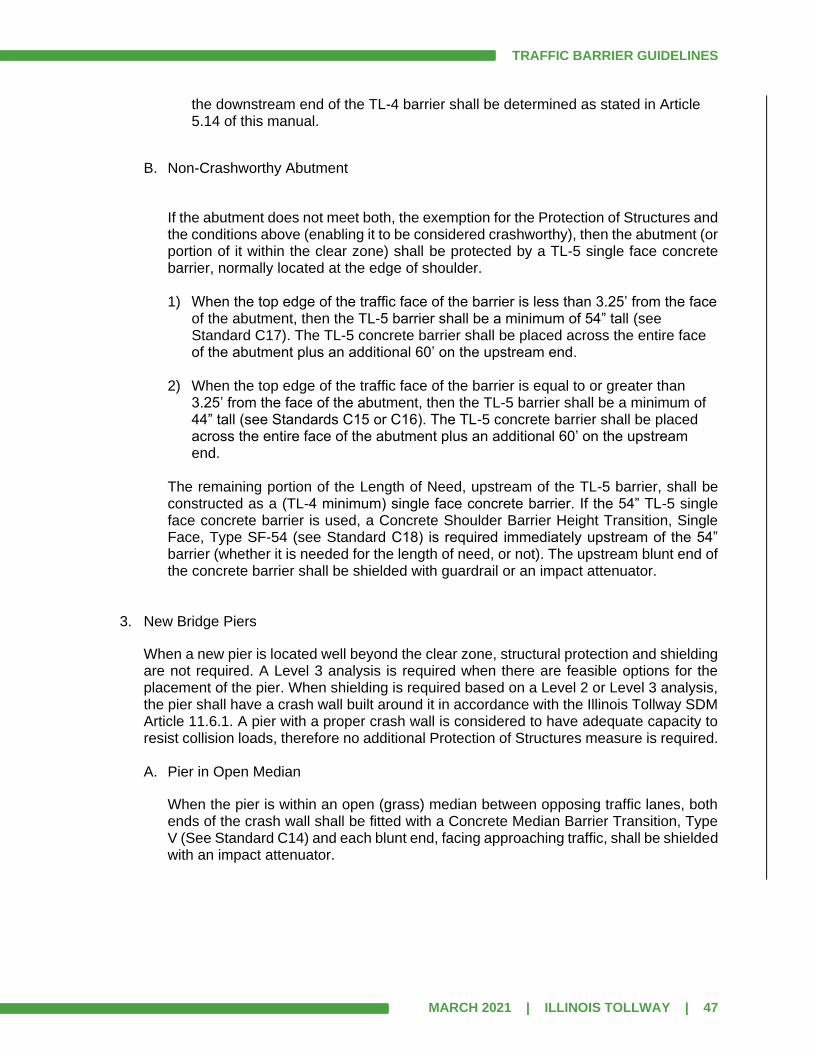
TRAFFIC BARRIER GUIDELINES
MARCH 2021 | ILLINOIS TOLLWAY | 47
the downstream end of the TL-4 barrier shall be determined as stated in Article 5.14 of this manual.
B. Non-Crashworthy Abutment
If the abutment does not meet both, the exemption for the Protection of Structures and the conditions above (enabling it to be considered crashworthy), then the abutment (or portion of it within the clear zone) shall be protected by a TL-5 single face concrete barrier, normally located at the edge of shoulder. 1) When the top edge of the traffic face of the barrier is less than 3.25’ from the face
of the abutment, then the TL-5 barrier shall be a minimum of 54” tall (see Standard C17). The TL-5 concrete barrier shall be placed across the entire face of the abutment plus an additional 60’ on the upstream end.
2) When the top edge of the traffic face of the barrier is equal to or greater than
3.25’ from the face of the abutment, then the TL-5 barrier shall be a minimum of 44” tall (see Standards C15 or C16). The TL-5 concrete barrier shall be placed across the entire face of the abutment plus an additional 60’ on the upstream end.
The remaining portion of the Length of Need, upstream of the TL-5 barrier, shall be constructed as a (TL-4 minimum) single face concrete barrier. If the 54” TL-5 single face concrete barrier is used, a Concrete Shoulder Barrier Height Transition, Single Face, Type SF-54 (see Standard C18) is required immediately upstream of the 54” barrier (whether it is needed for the length of need, or not). The upstream blunt end of the concrete barrier shall be shielded with guardrail or an impact attenuator.
3. New Bridge Piers
When a new pier is located well beyond the clear zone, structural protection and shielding are not required. A Level 3 analysis is required when there are feasible options for the placement of the pier. When shielding is required based on a Level 2 or Level 3 analysis, the pier shall have a crash wall built around it in accordance with the Illinois Tollway SDM Article 11.6.1. A pier with a proper crash wall is considered to have adequate capacity to resist collision loads, therefore no additional Protection of Structures measure is required. A. Pier in Open Median
When the pier is within an open (grass) median between opposing traffic lanes, both ends of the crash wall shall be fitted with a Concrete Median Barrier Transition, Type V (See Standard C14) and each blunt end, facing approaching traffic, shall be shielded with an impact attenuator.
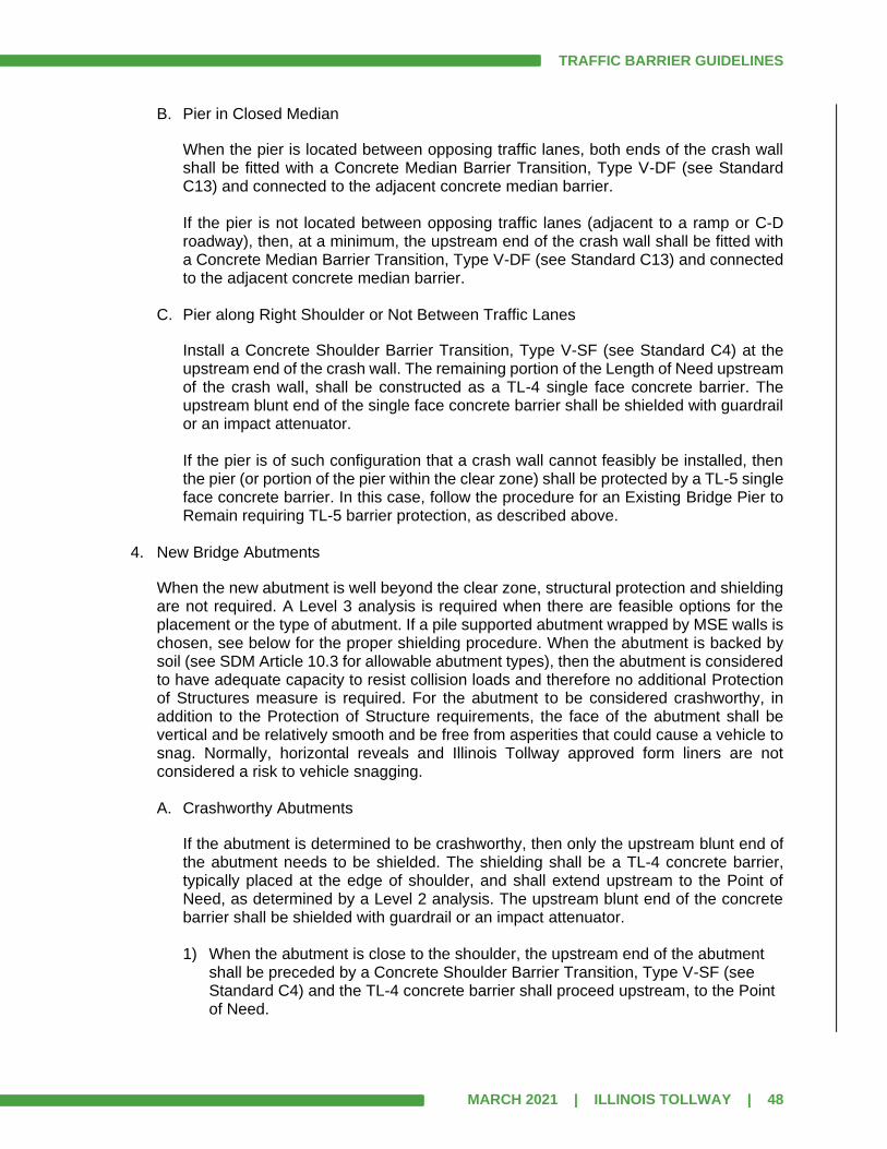
TRAFFIC BARRIER GUIDELINES
MARCH 2021 | ILLINOIS TOLLWAY | 48
B. Pier in Closed Median
When the pier is located between opposing traffic lanes, both ends of the crash wall shall be fitted with a Concrete Median Barrier Transition, Type V-DF (see Standard C13) and connected to the adjacent concrete median barrier. If the pier is not located between opposing traffic lanes (adjacent to a ramp or C-D roadway), then, at a minimum, the upstream end of the crash wall shall be fitted with a Concrete Median Barrier Transition, Type V-DF (see Standard C13) and connected to the adjacent concrete median barrier.
C. Pier along Right Shoulder or Not Between Traffic Lanes
Install a Concrete Shoulder Barrier Transition, Type V-SF (see Standard C4) at the upstream end of the crash wall. The remaining portion of the Length of Need upstream of the crash wall, shall be constructed as a TL-4 single face concrete barrier. The upstream blunt end of the single face concrete barrier shall be shielded with guardrail or an impact attenuator. If the pier is of such configuration that a crash wall cannot feasibly be installed, then the pier (or portion of the pier within the clear zone) shall be protected by a TL-5 single face concrete barrier. In this case, follow the procedure for an Existing Bridge Pier to Remain requiring TL-5 barrier protection, as described above.
4. New Bridge Abutments
When the new abutment is well beyond the clear zone, structural protection and shielding are not required. A Level 3 analysis is required when there are feasible options for the placement or the type of abutment. If a pile supported abutment wrapped by MSE walls is chosen, see below for the proper shielding procedure. When the abutment is backed by soil (see SDM Article 10.3 for allowable abutment types), then the abutment is considered to have adequate capacity to resist collision loads and therefore no additional Protection of Structures measure is required. For the abutment to be considered crashworthy, in addition to the Protection of Structure requirements, the face of the abutment shall be vertical and be relatively smooth and be free from asperities that could cause a vehicle to snag. Normally, horizontal reveals and Illinois Tollway approved form liners are not considered a risk to vehicle snagging. A. Crashworthy Abutments
If the abutment is determined to be crashworthy, then only the upstream blunt end of the abutment needs to be shielded. The shielding shall be a TL-4 concrete barrier, typically placed at the edge of shoulder, and shall extend upstream to the Point of Need, as determined by a Level 2 analysis. The upstream blunt end of the concrete barrier shall be shielded with guardrail or an impact attenuator.
1) When the abutment is close to the shoulder, the upstream end of the abutment
shall be preceded by a Concrete Shoulder Barrier Transition, Type V-SF (see Standard C4) and the TL-4 concrete barrier shall proceed upstream, to the Point of Need.

TRAFFIC BARRIER GUIDELINES
MARCH 2021 | ILLINOIS TOLLWAY | 49
2) If the barrier face and the abutment face cannot be aligned, then the TL-4 single
face concrete barrier shall be placed to shield the blunt end of the abutment and the downstream end of the TL-4 barrier shall be determined as stated in Article 5.14 of this manual.
B. Non-Crashworthy Abutments
Non-Crashworthy abutments are not allowed on the Illinois Tollway system. If a non-crashworthy abutment is approved by a design deviation, then the abutment (or the portion of it within the clear zone) shall be protected by a TL-5 single face concrete barrier. In this case, follow the procedure for Existing Bridge Abutments to Remain, requiring TL-5 barrier protection, as described above.
5. New or Existing MSE Walls in front of a Pile Supported Abutments
When a new or existing MSE wall in front of a pile supported abutment is well beyond the clear zone, Protection of Structures and shielding are not required. Since the MSE wall is not part of the substructure that directly supports the bridge, it does not fall under the requirements of the AASHTO LRFD for Protection of Structures. The MSE wall and associated wing walls or extension walls, are analyzed similar to other retaining walls. The MSE wall, when within the clear zone, shall be crashworthy and designed for TL-4 impact loading in accordance with the Illinois Tollway SDM; or be shielded by a TL-4 concrete barrier. For the face of the MSE wall to be considered crashworthy, it shall be vertical, relatively smooth and shall be free from protrusions and asperities that could cause a vehicle to snag, including precast slip joints. The presence of protrusions, precast slip joints or large asperities will cause the wall to be considered non-crashworthy. Normally, horizontal reveals and Illinois Tollway approved form liners are not considered a risk to vehicle snagging. When an MSE wall is considered non-crashworthy, it shall be shielded with a TL-4 concrete barrier as described in Article 5.7.10 regarding the discussion of retaining walls and noise abatement walls.
Bridge Cones
New embankment cones and bridge approach roadway embankments should be constructed to eliminate the need for traffic barrier along the lower roadway. Proposed bridge embankment cones at bridge abutments should be designed such that the steep slope facing traffic (transverse slope) is located outside of the upstream roadway’s clear zone or beyond the value in Table 5.8.1 when clear zone is undefined. Within the defined clear zone (or within the value in Table 5.8.1 when clear zone is undefined), the maximum unshielded transverse slope allowed to face approaching traffic shall be 1:10 (V:H). For the transverse slope facing away from approaching traffic located downstream of the slope wall, the maximum slope within the clear zone shall be 1:4 (V:H). The clear zone should be based on the slope of the slope wall.

TRAFFIC BARRIER GUIDELINES
MARCH 2021 | ILLINOIS TOLLWAY | 50
Retaining Wall Drop-Offs
Retaining wall drop-offs are considered an obstacle when the height differential is more than 3 feet. When a retaining wall is not present, but a near vertical (steeper than 1V:1.5H) drop-off is, it shall be considered the same case as a retaining wall drop-off. Because drop-offs are considered a more severe risk to run-off-the-road vehicles than embankments, a higher level of shielding should be considered. When shielding is required based on a Level 2 or 3 analysis, the drop-off shall be shielded with a TL-5 barrier, normally a reinforced concrete roadside barrier of at least 44” in height. The rigid barrier should be placed at the edge of shoulder, however when there are no other obstacles to shield and it is not feasible to place the barrier at the edge of shoulder, the barrier may be incorporated into the retaining wall parapet (See Articles 22.13 and 22.14 of the Structure Design Manual). For new retaining walls in areas where the foreslope is recoverable, and there are no other obstacles present, a Level 3 analysis should be performed to determine the most cost-effective location for the placement of the barrier. When an existing retaining wall is to remain, the rigid barrier shall be placed at the edge of shoulder.
Retaining Walls and Noise Abatement Walls
When it is not feasible to relocate an existing non-crashworthy NAW that is within the clear zone or just outside the clear zone, a Level 2 Analysis should be performed. When an existing non-crashworthy noise wall is not analyzed as a Level 3 Analysis, the report shall include a statement addressing why it was not done. Existing or proposed ground-mounted non-crashworthy noise walls or non-crashworthy retaining walls that are not well outside the clear zone shall be shielded with a TL-4 concrete barrier. When crashworthy, a retaining wall or noise wall shall have its upstream blunt end shielded. Note that traffic barrier terminals shall not be attached directly to retaining walls or noise abatement walls (even if crashworthy) and instead shall have a Concrete Shoulder Barrier Transition, Type V-SF (see Standard C4) affixed to the upstream end. The upstream end of the concrete barrier transition shall be treated as a blunt end and analyzed as such. Each proposed installation, whether crashworthy or non-crashworthy, should be evaluated using a Level 3 Analysis that considers construction, maintenance and crash costs, unless the proposed location is near the right-of-way line and well outside the clear zone.
Drainage Structures – General
Barrier required solely to shield a drainage structure is not desirable; an alternate drainage structure which does not require barrier should be utilized or the headwall or end treatment relocated well outside the clear zone as determined by a Level 3 Analysis.
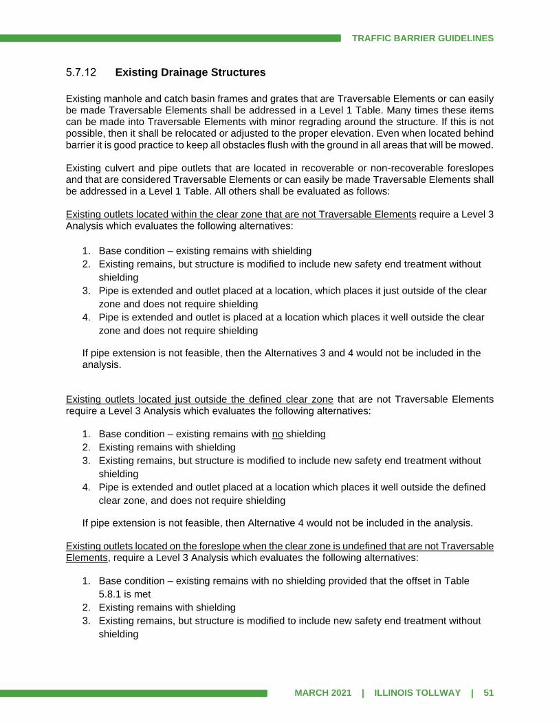
TRAFFIC BARRIER GUIDELINES
MARCH 2021 | ILLINOIS TOLLWAY | 51
Existing Drainage Structures
Existing manhole and catch basin frames and grates that are Traversable Elements or can easily be made Traversable Elements shall be addressed in a Level 1 Table. Many times these items can be made into Traversable Elements with minor regrading around the structure. If this is not possible, then it shall be relocated or adjusted to the proper elevation. Even when located behind barrier it is good practice to keep all obstacles flush with the ground in all areas that will be mowed. Existing culvert and pipe outlets that are located in recoverable or non-recoverable foreslopes and that are considered Traversable Elements or can easily be made Traversable Elements shall be addressed in a Level 1 Table. All others shall be evaluated as follows: Existing outlets located within the clear zone that are not Traversable Elements require a Level 3 Analysis which evaluates the following alternatives:
1. Base condition – existing remains with shielding
2. Existing remains, but structure is modified to include new safety end treatment without
shielding
3. Pipe is extended and outlet placed at a location, which places it just outside of the clear
zone and does not require shielding
4. Pipe is extended and outlet is placed at a location which places it well outside the clear
zone and does not require shielding
If pipe extension is not feasible, then the Alternatives 3 and 4 would not be included in the analysis.
Existing outlets located just outside the defined clear zone that are not Traversable Elements require a Level 3 Analysis which evaluates the following alternatives:
1. Base condition – existing remains with no shielding
2. Existing remains with shielding
3. Existing remains, but structure is modified to include new safety end treatment without
shielding
4. Pipe is extended and outlet placed at a location which places it well outside the defined
clear zone, and does not require shielding
If pipe extension is not feasible, then Alternative 4 would not be included in the analysis. Existing outlets located on the foreslope when the clear zone is undefined that are not Traversable Elements, require a Level 3 Analysis which evaluates the following alternatives:
1. Base condition – existing remains with no shielding provided that the offset in Table
5.8.1 is met
2. Existing remains with shielding
3. Existing remains, but structure is modified to include new safety end treatment without
shielding
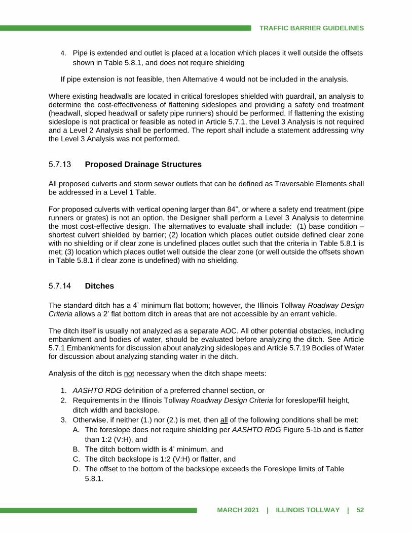
TRAFFIC BARRIER GUIDELINES
MARCH 2021 | ILLINOIS TOLLWAY | 52
4. Pipe is extended and outlet is placed at a location which places it well outside the offsets
shown in Table 5.8.1, and does not require shielding
If pipe extension is not feasible, then Alternative 4 would not be included in the analysis. Where existing headwalls are located in critical foreslopes shielded with guardrail, an analysis to determine the cost-effectiveness of flattening sideslopes and providing a safety end treatment (headwall, sloped headwall or safety pipe runners) should be performed. If flattening the existing sideslope is not practical or feasible as noted in Article 5.7.1, the Level 3 Analysis is not required and a Level 2 Analysis shall be performed. The report shall include a statement addressing why the Level 3 Analysis was not performed.
Proposed Drainage Structures
All proposed culverts and storm sewer outlets that can be defined as Traversable Elements shall be addressed in a Level 1 Table. For proposed culverts with vertical opening larger than 84”, or where a safety end treatment (pipe runners or grates) is not an option, the Designer shall perform a Level 3 Analysis to determine the most cost-effective design. The alternatives to evaluate shall include: (1) base condition – shortest culvert shielded by barrier; (2) location which places outlet outside defined clear zone with no shielding or if clear zone is undefined places outlet such that the criteria in Table 5.8.1 is met; (3) location which places outlet well outside the clear zone (or well outside the offsets shown in Table 5.8.1 if clear zone is undefined) with no shielding.
Ditches
The standard ditch has a 4’ minimum flat bottom; however, the Illinois Tollway Roadway Design Criteria allows a 2’ flat bottom ditch in areas that are not accessible by an errant vehicle. The ditch itself is usually not analyzed as a separate AOC. All other potential obstacles, including embankment and bodies of water, should be evaluated before analyzing the ditch. See Article 5.7.1 Embankments for discussion about analyzing sideslopes and Article 5.7.19 Bodies of Water for discussion about analyzing standing water in the ditch. Analysis of the ditch is not necessary when the ditch shape meets:
1. AASHTO RDG definition of a preferred channel section, or
2. Requirements in the Illinois Tollway Roadway Design Criteria for foreslope/fill height,
ditch width and backslope.
3. Otherwise, if neither (1.) nor (2.) is met, then all of the following conditions shall be met:
A. The foreslope does not require shielding per AASHTO RDG Figure 5-1b and is flatter
than 1:2 (V:H), and
B. The ditch bottom width is 4’ minimum, and
C. The ditch backslope is 1:2 (V:H) or flatter, and
D. The offset to the bottom of the backslope exceeds the Foreslope limits of Table
5.8.1.
TRAFFIC BARRIER GUIDELINES
MARCH 2021 | ILLINOIS TOLLWAY | 53
If all conditions in Item (3.) are not met and a Design Deviation has been approved, then analysis shall proceed in the following order:
1. If condition in (3.)(A.) is not met, then analyze foreslope as a Level 2 with LA measured
to the toe of slope.
2. If condition in (3.)(A.) is met but either condition in (3.)(B.) or (3.)(C.) is not met, and
offset to the bottom of backslope is:
A. Greater than the Foreslope value from Table 5.8.1, then no further analysis is
needed and AOC is shown on the Level 0 Table.
B. Less than the Foreslope value from Table 5.8.1, then analyze backslope as a Level 2
with LA = Foreslope value from Table 5.8.1.
Existing Roadway Lighting Installations
All existing ground-mounted light poles fall into one of four categories:
1. Pole with non-breakaway base/pole:
A. This should be removed and replaced with a current standard light pole and
foundation that also meets the definition of a Traversable Element. (Include in Level
1 Table).
B. If said pole cannot be placed such that it can easily be a Traversable Element, then
alternatives shall be evaluated in a Level 3 analysis.
2. Pole with breakaway device, but is not a Traversable Element:
A. Many times this can be made into a Traversable Element with minor regrading.
(Include in Level 1 Table).
B. If said pole cannot easily be made a Traversable Element, then alternatives shall be
evaluated in a Level 3 analysis.
3. Pole with a breakaway device and considered to be a Traversable Element can remain.
(Include in Level 1 Table).
4. Pole that is behind guardrail, but does not meet the minimum barrier clearance distance
for Type C (¼-post spacing) guardrail (See Article 9.2): This pole shall be relocated to a
new foundation at an offset that both meets the minimum barrier clearance distance for
guardrail and provides roadway lighting levels within criteria. In some cases, it may be
necessary to use Type B or Type C guardrail adjacent to the relocated pole. (Level 2
obstacle --- include with AOC that warranted guardrail).
Existing handholes and similar items shall be addressed in a Level 1 Table and fall into one of two categories:
1. Item that is not a Traversable Element can usually be made into a Traversable Element
with minor regrading. If minor regrading is not sufficient, then obstacle shall be relocated
or adjusted to become a Traversable Element.
2. Item that is considered to be a Traversable Element can remain.
TRAFFIC BARRIER GUIDELINES
MARCH 2021 | ILLINOIS TOLLWAY | 54
If located behind guardrail or a terminal, the obstacle (even if flush with surface) shall provide space around the posts equal to the leave-out requirements (See Article 9.7). The relocation of existing lighting controllers will require a Level 3 Analysis to evaluate alternatives. If relocation is not feasible, then the existing controller shall be shielded and a Level 2 Analysis performed. The report shall include a statement addressing why the Level 3 Analysis was not performed.
Proposed Roadway Lighting Installations
All proposed ground mounted light poles should be placed such that they can be defined as Traversable Elements and addressed in a Level 1 Table. All proposed ground mounted light poles behind guardrail should be located based on Illinois Tollway Standard Drawing H1. These shall be noted in the Level 2 analysis for the AOC that warranted the guardrail. Note that placement of the light pole at the standard offset will result in the need for Type C guardrail if Gutter, Type G-3 is present. Proposed lighting controllers shall be shielded by otherwise warranted barrier or located well outside the clear zone, preferably on the backslope or near the ROW fence. If this is not possible, the Designer shall perform a Level 3 Analysis to evaluate alternatives.
Communication Systems and ITS Devices
The Designer shall consider the future maintenance needs for any ITS unit and consider maintenance/access for all proposed and relocation alternatives. The Illinois Tollway ITS Group shall be consulted for input on latest installation issues and maintenance. If relocation is not feasible, then the existing device shall be shielded and a Level 2 Analysis performed. The report shall include a statement addressing why the Level 3 Analysis was not performed. When performing a Level 3 Analysis, include costs to build special access (if required) for each alternative. For example, if a widened shoulder, access driveway, or additional grading would be necessary for an alternative it should be included in the initial costs.
Utility Poles
The determination to relocate existing poles and/or lines should be the result of a Level 3 Analysis and early coordination with the Illinois Tollway Utility Group. The Level 3 analysis should be performed early in the design phase so that the necessary work orders, if required, can be prepared and sent to the appropriate utility company to initiate relocation work. The Level 3 Analysis should account for all Illinois Tollway relocation costs. If the Designer determines that a Level 3 analysis is not necessary or relocation is not feasible, then the item shall be evaluated as a Level 2 item. The report shall include a statement addressing why the Level 3 Analysis was not performed.

TRAFFIC BARRIER GUIDELINES
MARCH 2021 | ILLINOIS TOLLWAY | 55
Bodies of Water
Bodies of water greater than 2’ in depth (normal water elevation) within the clear zone shall be shielded with barrier (Level 2 Analysis). Designer shall consider the use of TL-4 single-face concrete barrier to shield a severe water obstacle within the clear zone or just outside the clear zone. Determination of barrier warrants for bodies of water greater than 2’ in depth located outside of the clear zone shall be based upon a Level 3 Analysis. It is suggested to use a very severe vertical drop-off feature in RSAP for the water obstacle.
Rock Cuts
A Level 3 Analysis shall evaluate the following alternatives: (1) additional excavation to eliminate/minimize the obstacle, (2) leaves the face as is, or (3) provide barrier to shield the rock face.
Right-of-Way Line
It is not possible to predict or control what an adjacent property owner might do or construct within their property. Although there may not be any apparent obstacles at the time of construction, it is not known if it will remain that way. If there is a non-traversable obstacle present outside of the Illinois Tollway ROW line, it shall be analyzed according to the flowcharts for analysis of obstacles (Figures 5.6a and 5.6b). If there is no obstacle present, the Designer shall use engineering judgement to determine if shielding is required. This determination shall be documented with the BWA. If the Designer has determined that ROW line needs to be shielded as an alternative, Article 5.8.5 discusses how to code this as a feature in RSAP.
Blunt Ends
The blunt end of a concrete barrier (single-face or double-face) or parapet (on bridge or retaining wall), that is facing approaching traffic located near the edge of shoulder shall be analyzed as a Level 2 and shall be shielded with an impact attenuator or guardrail. Absent other nearby AOCs, this blunt end obstacle will yield the minimum shielding (upstream terminal + downstream terminal with no guardrail). Detailed determination of LON is not required in this case and labels for X, Y and the PON are not required on the site plan. If other nearby AOCs exist, they should be analyzed first. The blunt end of a concrete barrier (single-face or double-face), parapet (on bridge or retaining wall), or wall (retaining wall with no parapet or the first column of a crash-worthy NAW) that is facing traffic located away from the shoulder shall be analyzed as a Level 3 unless located well outside of the clear zone. Alternatives for the Level 3 analysis at a minimum shall include:

TRAFFIC BARRIER GUIDELINES
MARCH 2021 | ILLINOIS TOLLWAY | 56
1. Do nothing – No shielding. This alternative is only feasible if blunt end is located outside
a defined clear zone or the offset exceeds the value in Table 5.8.1 when clear zone is
undefined.
2. Shield blunt end with free-standing guardrail along the shoulder.
3. Shield blunt end with an impact attenuator.
The back side of a concrete barrier is a potential obstacle to adjacent roadways and shall be analyzed as a Level 2 if determined to be an obstacle.
5.8 RSAP Guidance
The RSAP software has undergone a major rewrite which was finalized in late 2012. However, until further notice, the Designers shall use Version 2 of RSAP for any Level 3 Analyses.
Determination of Alternatives
As part of the barrier warrant process there are several types of AOCs that may require a Level 3 Analysis. Use Figures 5.6a and 5.6b to determine the required analysis level. If a Level 3 analysis is warranted, then the designer needs to use good engineering judgement when selecting the alternatives to evaluate. Each potential obstacle has a discussion of items to consider and below is some additional guidance for the selection of alternatives.
1. Only consider alternatives that are feasible (for example, an alternative that leaves an obstacle unshielded in the clear zone violates Illinois Tollway policy and therefore is not feasible).
2. The following values shall be exceeded when relocating an obstacle or when considering leaving an obstacle unshielded when the clear zone is undefined:
Table 5.8.1
Design Speed
(mph)
Minimum Offset from EOTW (ft)
Foreslopes Backslopes (See Note)
Less than or equal to 40 18 18
45-50 28 18
55 32 18
60 44 22
65-70 46 24
Note: Backslope column is only used when no foreslope exists.
3. An obstacle shall not be relocated to an unshielded critical foreslope.
TRAFFIC BARRIER GUIDELINES
MARCH 2021 | ILLINOIS TOLLWAY | 57
4. When considering relocation of an obstacle, the designer should consider relocation upstream, downstream in addition to changing the offset from the EOTW.
5. The Designer should consider combining relocation of an obstacle with a flattening of the foreslope, if feasible.
6. Use the Foreslope values in Table 5.8.1 as minimums for LA when calculating the minimum shielding for a transverse slope (+ or -) that is downstream of a non-recoverable foreslope.
7. Alternatives for sign truss span lengths or cantilever arm lengths shall not exceed the maximums shown on the Illinois Tollway Standard Drawings.
8. High initial relocation costs shall not be the sole reason for eliminating an alternative since construction/installation cost is only one of the costs that are factored into the Level 3 Analysis.
9. Values shall be adjusted using a Curve Correction Factor (KCZ) from AASHTO RDG, Table 3-2, when on the outside of a horizontal curve whose Radius < 2950’.
Crash Costs
Global Value of a Fatality – The suggested value for the cost of a fatality used in the program has been set at $1,000,000. However, most Federal agencies are using a much higher value for a fatality. Accordingly, the Illinois Tollway has determined that a value of $5,000,000 shall be used for barrier warrant analyses involving fatalities. Therefore, when using the RSAP program the crash costs need to be adjusted to the following:
1. $5,000,000 for fatal crashes
2. $500,000 for severe injury crashes.
3. $100,000 for moderate injury crashes.
4. $30,000 for minor injury crashes.
5. $6,000 for PDO (property damage only) crashes.
Input Values
1. Use program default values for:
• Life cycle (25 years)
• Discount Rate (4%)
• Encroachment rate adjustment factor (1)
• Traffic Growth Factor (1.0%) (unless project specific data is available)
2. Use design speed instead of speed limit
3. Use total ADT (sum of both directions in construction year)
4. Use total number of lanes (If number of lanes in each direction is different, use 2 times
the number of lanes in the direction being analyzed)
5. Median width is measured from inside EOP to inside EOP (includes both median
shoulders and median barrier)

TRAFFIC BARRIER GUIDELINES
MARCH 2021 | ILLINOIS TOLLWAY | 58
Construction Unit Prices
Use the following unit prices for all RSAP analyses:
1. $22/LF for Type A guardrail (6’ posts)
2. $26/LF for Type A guardrail (9’ posts)
3. $33/LF for Type B guardrail (6’ posts)
4. $36/LF for Type B guardrail (9’ posts)
5. $42/LF for Type C guardrail (6’ posts)
6. $46/LF for Type C guardrail (9’ posts)
7. $100/post for additional posts
8. $5/LF for guardrail removal (incl. terminals)
9. $2,500 for Type T1 (Special) Terminal
10. $2,000 for Type T1-A (Special) Terminal
11. $1,000 for Type T2 Terminal
12. Type T5 Terminal is no longer used
13. $3,000 for Types T6 and T6B Terminals
14. $600 for Type T10 Terminal
15. $2/LF/yr for maintenance of all guardrail and terminals
16. $35,000 for fully re-directional impact attenuator
17. $1,500/yr for maintenance of impact attenuator (this is based on one crash per year and
should be adjusted based on the predicted crashes/year from RSAP)
18. $28/LF for Gutter, Type G-3 or G-3 Modified
19. $25/LF for Gutter, Type G-2 or G-2 Modified
20. $200/LF for 44” single-face reinforced concrete barrier and base (TL-4)
21. $400/LF for 44” single-face reinforced concrete barrier and base (TL-5)
22. $500/LF for 54” single-face reinforced concrete barrier and base (TL-5)
23. $5,000 for relocation of a light pole (does not include grading to make pole a Traversable
Element)
24. $10,000 for new light pole and foundation (does not include grading to make pole a
Traversable Element)
25. $10,000 for relocation of an MVDS pole
26. $40,000 for relocation of a lighting controller (unless project specific information is
available)
27. $20,000 for relocation of a CCTV pole (unless project specific information is available)
28. $2000/LF for sign structure (span type)(includes foundations)
29. $4000/LF for sign structure (cantilever type)(includes foundation)
30. $2000/LF for sign structure (monotube type)(includes foundations)
31. $xxxx/LF for ITS gantries (includes foundations)(Check with Illinois Tollway PM for
current unit price)
32. $25/CY for embankment/excavation
33. $200/SF for highway bridge deck (includes all bridge elements such as beams,
substructure and parapet)

TRAFFIC BARRIER GUIDELINES
MARCH 2021 | ILLINOIS TOLLWAY | 59
For items not listed, the Designer should recommend a unit price. Include MOT costs if there is a significant difference between alternatives. However, landscaping, erosion control and signing and marking items should not be included.
RSAP Features
A feature is not needed for cross sectional elements that are relatively flat (flatter than 1:10 (V:H)). This usually applies to shoulders and ditch bottoms. All features should be located on the left or right side of the roadway. Do not use median side. Coding of Guardrail Installation
1. All free-standing guardrail installations require at least 4 features.
2. Guardrail and Terminals shall be coded as follows:
Guardrail shall be coded as TL-3 guardrail. Terminal Type T1 (Special) shall use 2 features:
• 12.5’ TL-3 terminal at upstream flare rate of 50:1 with an offset of L2 + 0.94’
• 34.38’ TL-3 guardrail at upstream flare rate of 50:1 with an offset of L2 + 0.69’
Terminal Type T1-A (Special) shall use 2 features:
• 12.5’ TL-3 terminal at upstream flare rate of 25:1 with an offset of L2 + 0.88’
• 9.38’ TL-3 guardrail at upstream flare rate of 25:1 with an offset of L2 + 0.38’
Terminal Type T2 shall use 12.5’ TL-3 terminal with an offset of L2. Terminal Type T5 is no longer used Terminal Type T6 shall be coded the same as guardrail Terminal Type T6B shall be coded the same as guardrail Terminal Type T10 is not coded because it has no length
User Defined RSAP Features Most features are available in the program. The exception is 1:2.5 (V:H) foreslopes. A User Defined Feature for 1:2.5 (V:H) foreslope shall use the following SI values for various fill heights as shown in Table 5.8.5.
Table 5.8.5
Fill Height SI at 0 mph SI at 60 mph
6” 0 2.0
1’ 0 3.1
5’ 0 3.4
9’ 0 4.6
20’ 0 5.0
>=30’ 0 5.4
Backslopes steeper than 1:3 and flatter than 1:2 shall be treated as 1:2 for the purposes of RSAP analysis.

TRAFFIC BARRIER GUIDELINES
MARCH 2021 | ILLINOIS TOLLWAY | 60
Coding of ROW line (if Designer has determined that ROW line needs to be shielded) Use a fixed object feature [Type 8. Rectangle, W 0.5 m (1.5 ft), H > 1.0 m (3 ft)] for the ROW line. The width of the feature should be 10’. See Article 5.7.21 for information on analyzing this type of AOC. Coding of Headwalls, Sloped Headwalls, Box Culverts The height used shall be the maximum drop-off height at the face of the headwall or end of box culvert, accounting for the waterway opening and the thickness of the top slab. Erroneous Severity Indices in RSAP Results for Positive Intersecting Slopes of 1:10 and 1:8 (all heights) are extremely high compared to default values given in the RSAP documentation. To work around this bug in the software, use a Positive Intersecting Slope of 1:6 for evaluation of 1:10 transverse slopes facing approaching traffic.
Interpreting RSAP Results
To analyze the results properly, the incremental B/C ratios shall be evaluated on a pair-wise basis, starting from the alternative with the lowest direct cost (sum of annual costs --- installation, maintenance and repair). The RSAP report lists the alternatives in the order that they should be evaluated. See Figure 5.8.6. The Illinois Tollway uses a threshold value for funding safety projects at a B/C ratio of 1.5 (that is when the B/C ratio is 1.5 or greater the alternative is considered worth doing).
When B/C ratios are marginal (1.0 to 1.49) or when the total cost of each alternative is relatively low, the alternative that provides the safest conditions shall be selected.

TRAFFIC BARRIER GUIDELINES
MARCH 2021 | ILLINOIS TOLLWAY | 61
Figure 5.8.6 RSAP Output – B/C Evaluation
5.9 Lateral Offset of Barrier
The placement of traffic barriers shall be in accordance with the requirements of Chapter 5 of the AASHTO RDG, Illinois Tollway Standard Drawings and manufacturer requirements. The face of all guardrail shall be placed 1’ beyond the edge of a paved shoulder (without gutter), except as otherwise indicated in the Illinois Tollway Standard Drawings. When guardrail is used with gutter, the offset from the edge of paved shoulder to the face of rail shall be as shown on Illinois Tollway Standard Drawing C1. For more information on the use of gutters see the Illinois Tollway Roadway Design Criteria. At plazas (mainline or ramp) the guardrail placed adjacent to existing curb shall be located such that the face of the guardrail is aligned with the face of the curb if the curb is properly located. If not properly located, existing curb shall be removed, and new curb and guardrail shall be constructed in accordance with the aforementioned requirements. Desirably, rigid concrete barriers, parapets and walls shall be placed no closer to the travel lanes than the paved shoulder width plus the width of any required gutter (barrier base). When these rigid barriers are placed closer to the EOTW than the Shy Line Offset (see AASHTO RDG Table 5-7), there is a tendency for drivers to reduce speed or move away from the barrier, which may cause an unsafe condition. For ramp pavements, the minimum left edge lateral clearance for rigid barriers shall be 6’. All clearances to rigid barriers along curved alignments shall meet horizontal stopping sight distance requirements, which may require wider shoulders or barrier placed further from the EOTW than normal.

TRAFFIC BARRIER GUIDELINES
MARCH 2021 | ILLINOIS TOLLWAY | 62
Access to certain ITS devices located behind barrier may require wider shoulders or barrier placed further from the EOTW than normal. The Designer shall consider type of maintenance vehicle and whether or not a gap is required in the barrier for worker access. Flared guardrail installations require more lateral distance from the edge of shoulder and are therefore usually not practical for new barrier design because of the embankment widening needed. Existing installations can remain if they meet the taper rate criteria in AASHTO RDG Table 5-9. The cross slope between the edge of the shoulder and the barrier shall be no steeper than 1:10 (V:H). The installation of barrier in gore areas is to be avoided, through the construction of relatively flat gore slopes and recovery areas. When it is not cost-effective to do this, barrier along the mainline and ramp shoulders shall terminate at the same point and be shielded with an impact attenuator. Each run of barrier should taper toward the roadway from an intersection near the back of the gore. It is desirable to place the impact attenuator as far downstream as possible to keep the gore clear of obstacles. It is also desirable to use a standard width impact attenuator rather than a wide impact attenuator. The use of a wide impact attenuator needs advanced approval from Illinois Tollway Maintenance.
5.10 Calculation of Dimension Y
Dimension Y, from Figure 4.6, is only needed to determine dimension X and is only true at the upstream end of X and thus should not be shown elsewhere. When the Design Speed is more than 40 mph, for calculation purposes Y = L2 + 0.69’. When the Design Speed is 40 mph or less and using a TBT Type T1-A, then for calculation purposes Y = L2 + 0.38’. In a later step, when the station limits of the terminals are determined, the actual offset to the tapering TBT at the PON (upstream end of dimension X) will be less than the calculated dimension. This actual dimension shall not be shown in the report. When calculating the upstream end of a rigid concrete barrier, Y should be the offset to the back face of the concrete barrier. This procedure applies to guardrail installations that are placed parallel to the roadway and that will have a TBT Type T1 (Special) or Type T1-A (Special) for the upstream terminal. Infrequently, a flared installation will be required for the guardrail. In that case, the Type T1 and Type T1-A terminals are still placed at the standard taper rates of 50:1 and 25:1, respectively, and the calculation for Y (and X) should be done graphically.
5.11 Calculation of Dimension X
The procedure outlined in Section 5.6.4 of the AASHTO RDG and as supplemented herein, shall be used. The LON is defined as the total length of a longitudinal barrier, measured with respect to the EOTW, needed to shield an AOC. It is comprised of two parts: (1) the length of the AOC (including overlap and 25 degree adjustment when applicable – See Article 5.14); and (2) the length from the upstream end of the AOC to upstream end of the barrier needed to shield the AOC from an errant vehicle. The second part of the LON is called dimension X. The upstream end of X is the PON and is the theoretical upstream point where shielding shall begin.

TRAFFIC BARRIER GUIDELINES
MARCH 2021 | ILLINOIS TOLLWAY | 63
Dimension X only needs to be determined when trying to locate the free-standing upstream end of a barrier. This procedure applies to guardrail installations that are placed parallel to the roadway and that will have a TBT Type T1 (Special) or Type T1-A (Special) for the upstream terminal. Infrequently, a flared installation will be required for the guardrail. In that case, the Type T1 and Type T1-A terminals are still placed at the standard taper rates of 50:1 and 25:1, respectively, and the calculation for X should be done graphically. When the upstream end of the guardrail installation will be attached to a structure (bridge rail, retaining wall), Dimension X is not determined and then LON = length of the AOC is the distance from the downstream end of the structure to the downstream end of the obstacle.
Using Formula to Determine X
The formula to calculate X is (LA – Y)/(LA/LR), where LA is the lateral extent of the area of concern and LR is the runout length. LA is discussed in Article 5.5. The equations for X shown in AASHTO RDG Section 5.6.4 shall not be used. Calculation for dimension Y is shown in Article 5.10. When the AOC or any portion of LR is located on the inside of a curve, the graphical method will give a larger value for X than the formula. Therefore, when the radius is less than 5000’, the formula shall be used to determine X for AOCs on the inside of a curve. For radii larger than or equal to 5000’, either the formula or the graphical method may be used to determine X for AOCs on the inside of the curve.
Using Graphical Solution to Determine X
A graphical solution for X is the only acceptable method when the upstream end of the AOC or any portion of LR is located on the outside of a horizontal curve. The tangent runout path should be drawn tangent to the curve at the EOTW and connect to a point that is a distance of LA from the edge of traveled way at the upstream end of the AOC. If the length of the tangent runout path exceeds LR, then LR shall be used to determine the upstream end of the runout path. When using LR in this case, the runout path will not be tangent to the EOTW. The PON is the intersection of the runout path and an arc concentric with the EOTW that is Y distance from the EOTW. Calculation for dimension Y is shown in Article 5.10. The graphical method shall also be used when any of the following occur within LR:
1. Where a shoulder width transition exists
2. When the outside lane is tapering
3. When there is a kink in the EOTW
4. When the guardrail installation is flared
See AASHTO RDG, Figure 5-48 for an example problem of a barrier design on the outside of a horizontal curve.
TRAFFIC BARRIER GUIDELINES
MARCH 2021 | ILLINOIS TOLLWAY | 64
5.12 Type of Barrier – Guardrail versus Concrete Barrier
The type of barrier needed is dependent on factors, such as, required Test Level of shielding, other nearby obstacles, site conditions and proximity of the obstacle to the barrier. In many cases, a TL-3 barrier is adequate for the obstacle being analyzed. The most cost-effective TL-3 barrier is typically guardrail. In locations where higher Test Levels are necessary, a concrete barrier shall be considered. The Illinois Tollway uses concrete barriers when TL-4 and TL-5 barriers are required. These concrete barriers are considered rigid since they do not deflect when impacted, however, the lean over of larger and taller vehicles, must be considered. This lean over area is called Zone of Intrusion. This concept is further discussed in the AASHTO Roadside Design Guide. Guardrail is considered semi-rigid barrier since the system deflects upon impact. This deflection distance needs to be kept clear of above grade rigid obstacles in order for the guardrail system to function properly. In locations where the minimum barrier clearance between the back of guardrail posts and near edge of the obstacle cannot be met, single-face reinforced concrete barrier (TL-4) shall be used. See Article 9.2 for barrier clearance discussion. Concrete barrier shall be used along the outside edge of narrowing shoulder areas approaching an existing abutment or bridge pier that is to remain. See Article 13.2.1, Use of Single-Face Barrier along Shoulder Taper for Illinois Tollway policy. All flared installations of concrete barrier shall meet the criteria in AASHTO RDG Table 5-9 for taper rate. When analyzing bridge piers (without crash walls), bridge abutments that are not soil backed, or other non-crashworthy bridge abutments, a TL-5 reinforced concrete barrier shall be used to shield the bridge support when any portion of the bridge element is within the clear zone. When retaining wall drop-offs need to be shielded, a TL-5 reinforced concrete barrier, 44” tall shall be used and should be placed at the edge of shoulder. When ground-mounted non-crashworthy noise abatement walls and non-crashworthy retaining walls (traffic runs along the face), need to be shielded, they shall be shielded by a TL-4, 44” tall concrete barrier. Standard guardrail with barrier terminals is typically used to shield most other obstacles. See Article 5.16 for minimum installation length of free-standing guardrail. CMB should only be used in open medians to reduce the likelihood of a crossover head-on crash. CMB is typically not used to shield roadside obstacles.
5.13 End Treatment of Barrier
Guardrail placement requires the use of suitable traffic barrier terminals at each end of the guardrail installation. Single-Face reinforced concrete barrier requires the use of a suitable traffic barrier terminal on the upstream end of the barrier. Crash walls for shoulder and median piers require the use of concrete transition sections on the upstream end. Terminals shall conform to the Illinois Tollway Standard Drawings, Special Provisions and Standard Specifications. See Section 10.0 for a detailed description and usage guide for all terminal types.
TRAFFIC BARRIER GUIDELINES
MARCH 2021 | ILLINOIS TOLLWAY | 65
Concrete median barrier requires the use of impact attenuators for shielding of the approach end. Impact attenuators shall conform to the requirements of the AASHTO RDG (latest edition) and AASHTO MASH. Double rail MGS guardrail (one rail on each side of a post) shall not be used. Guardrail connection to bridge parapets requires a suitable TBT as shown in the Illinois Tollway Standard Drawings. Guardrail connection directly to bridge piers is not typically used – a concrete shoulder barrier transition shall be used.
5.14 Barrier Limits Determination
After the PON is determined, the limits of the individual pay items can be determined. Dimension X is the length of shielding required upstream of the AOC and does not include any shielding along the AOC. If X is greater than or equal to 71.28’ and Design Speed is over 40mph, the upstream end of the Type T1 (Special) terminal needs to be at least 12.5’ and no more than 25’ upstream of the PON, unless otherwise warranted (See Article 3.12). If X is greater than or equal to 46.28’ and Design Speed is 40mph or less, the upstream end of the Type T1-A (Special) terminal needs to be at least 12.5’ and no more than 25’ upstream of the PON, unless otherwise warranted (See Article 3.12). When the value for X is less than the above values for the specified Design Speeds, the minimum installation of a TBT Type T6 (or T6B) and a TBT Type T1 (Special) or Type T1-A (Special) should be installed. When this occurs the distance from the PON to the upstream end of the Type T1 (Special) or Type T1-A (Special) Terminal could be greater than 25’. Guardrail lengths should be rounded up to the nearest 12.5’ section or multiple thereof, unless between two fixed traffic barrier terminals (for example, when attached to structures on each end so the location is fixed). Once guardrail length and terminal limits are established, the Designer shall verify that the recovery area adjacent to the T1 or T1-A terminal is clear of obstacles. See Figures 10.3.1c and 10.3.2b, respectively. Additional lengths of guardrail should not be installed for the purposes of shifting the recovery area to avoid obstacles unless no reasonable alternatives exist. The amount of each TBT that can be applied toward the LON requirement varies. See detailed descriptions for each terminal in Section 10.0. When locating a free-standing terminal (TBT Type T2) at the downstream end of a run of guardrail two conditions may exist. See Article 10.5.1 and Figure 5.14.
Condition 1: When an obstacle is located 6’ or less from the back of guardrail posts, the guardrail shall be extended an additional 25’ past the downstream end of the obstacle. Minimum guardrail clearance shall be met for the Type of guardrail used. See Article 9.2.
TRAFFIC BARRIER GUIDELINES
MARCH 2021 | ILLINOIS TOLLWAY | 66
Condition 2: When the obstacle is located more than 6’ from the back of the guardrail posts, the downstream end of the guardrail should be shortened using a 25-degree angle from the downstream end of the obstacle, then the guardrail shall be extended an additional 25’, ahead of the Type T2 terminal. This is similar to IDOT’s procedure.
The downstream end of a rigid barrier, shielding an obstacle, should be determined using Condition 2 (25 degree angle) regardless of the offset from the barrier to the obstacle, except that the 25’ is not added to the length of the barrier. However, when a LT-5 barrier is used to protect a bridge structure in compliance with Article 5.4, the downstream end of the TL-5 barrier shall align with the downstream end of the structure. Generally each AOC should be analyzed separately and the barrier limits determined except as defined in Article 5.6.3. Even when AOCs are in close proximity to each other, a separate analysis should be performed and presented on an individual Site Plan. When all of the AOCs within an area have been completed separately, then overlapping barrier and gaps need to be addressed. The resulting barrier or barriers shall be shown on a Summary Site Plan.
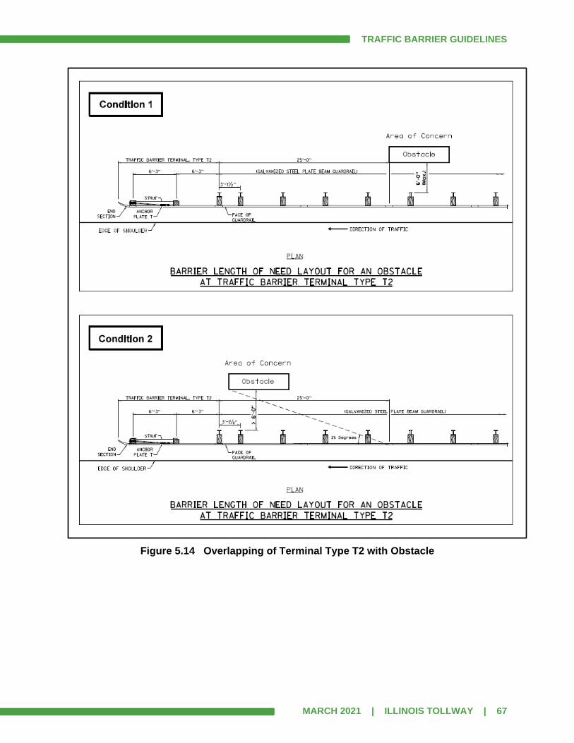
TRAFFIC BARRIER GUIDELINES
MARCH 2021 | ILLINOIS TOLLWAY | 67
Figure 5.14 Overlapping of Terminal Type T2 with Obstacle
TRAFFIC BARRIER GUIDELINES
MARCH 2021 | ILLINOIS TOLLWAY | 68
5.15 Analysis of Existing Barriers
The analysis of existing barrier installations is a three-step process. First, the need for barrier should be re-established. The mere presence of existing barrier does not in itself constitute a warranting condition. Barrier warrants shall be determined through site surveys, evaluation of sideslopes and obstacles and identification of specific safety issues. Secondly, alternate methods for the elimination of identified obstacles should be evaluated, and recommendations for the most cost-effective method shall be presented. Finally, the recommended measure shall be incorporated into the contract plans for the improvement. This involves detailed engineering for measures such as slope flattening or obstacle relocation, or the selection and design of suitable traffic barriers, if warranted. The Designer shall make every effort to identify and evaluate alternatives that eliminate or minimize roadside obstacles and shall evaluate the cost-effectiveness of all such alternatives.
5.16 Minimum Length of Guardrail
The Illinois Tollway minimum length of a “free-standing” run of guardrail is based on several crash tests. A typical free-standing installation usually includes a Type T1 (Special) terminal on the upstream end and a Type T2 terminal on the downstream end. For this installation, the minimum length of guardrail required between these two terminals is 112.5’. A free-standing installation with a Type T1-A (Special) terminal on the upstream end and a Type T2 terminal on the downstream end requires 137.5’ of guardrail between these two terminals to meet the minimum length requirement. However, it may be more cost effective to build a section of single-face reinforced concrete barrier with a guardrail installation consisting of a Type T6 or Type T6B terminal and a Type T1 (Special) or Type T1-A (Special) terminal rather than build the minimum free-standing guardrail installation. For guardrail attached to the upstream end of a structure, the minimum installation consists of a Type T6 or Type T6B terminal and a Type T1 (Special) or Type T1-A (Special) terminal. A section of guardrail is typically not required between the terminals. However, when G-3 gutter approaches a safety shape parapet or vertical face wall where only 1 foot of gutter is provided, then an additional section of MGS rail (12.5’) is required on the upstream end of the Type T6 terminal to extend the terminal taper. The additional section of MGS guardrail is required only along mainlines and C-D roadways where a minimum terminal installation is proposed using a Type T6 terminal and G-3 gutter, and the downstream gutter width is 1 foot or less at the face of wall or parapet. The additional section of MGS rail is not needed for the taper with G-2 gutter or when the Type T6 terminal is attached to a single-face concrete barrier with a 2’ gutter.
5.17 Minimum Gap in Guardrail
Gaps of less than 100’ between guardrail installations should be avoided (clear distance between ends of terminals); continuous guardrail should be provided. (Note that this is different than IDOT policy).

TRAFFIC BARRIER GUIDELINES
MARCH 2021 | ILLINOIS TOLLWAY | 69
5.18 Minimum Length of Single-Face Concrete Barrier
The minimum length of single-face concrete barrier shall be 25’-0” for 44” high (TL-4) barrier and shall be 40’-0” for all TL-5 single-face reinforced concrete barrier, whether it is 44” tall or 54” tall, exclusive of end treatments and transition sections. If shorter lengths are required, they shall be structurally designed for the specific application and a design deviation shall be submitted and approved.

TRAFFIC BARRIER GUIDELINES
MARCH 2021 | ILLINOIS TOLLWAY | 70
SECTION 6.0 PRESENTATION OF BARRIER WARRANT ANALYSES
Barrier warrant analyses shall be presented in an organized format, which presents the criteria, assumptions, existing conditions, analyses, layouts and recommendations for shielding, reduction or elimination of the obstacle at each location. Within a project’s limits, a standardized analysis format shall be used for each location evaluated. All locations for a project should be included in one document. Depending on the number of locations that are evaluated, multiple volumes might be necessary. The full report shall be presented electronically in a PDF format. The final BWA for each contract is stored electronically in the Illinois Tollway’s WBPM system using the BWA process. This document is saved as a record of the analysis performed for each roadside safety hardware device that was recommended and installed as part of that contract. It is imperative that the electronic version of the final barrier warrant submitted by the DSE matches the Final Plans. The amendment of a Final BWA is addressed in Article 7.7. These documents may be used to show that a proper analysis was performed to justify what was built in the field. For each Level 2 AOC, the order of sheets should be as follows (note that the RDG Figure 5-1b should only be included when necessary):
1. Data Sheet
2. Calculation Sheet
3. AASHTO RDG Figure 5-1b
4. Site Plan
5. Speed Profile (note that all speed profiles may be presented together, usually in an
Appendix, see Article 6.9)
6. Cross Sections (note that all cross sections may be presented together, see Article 6.8)
For each project, the following information shall be provided in the BWA document:
6.1 Cover Sheet
The Cover Sheet shall include:
1. Project description with milepost limits
2. Design Contract Number
3. Construction Contract Number (if known)
4. Submittal Date including month, day and year
5. Submittal milestone (preliminary, pre-final, final)
6. Designer name and logo
7. Prime Consultant, if Designer is a sub-consultant
8. Volume #, if applicable
9. Professional Engineer’s Seal and signature (Final submittal only)

TRAFFIC BARRIER GUIDELINES
MARCH 2021 | ILLINOIS TOLLWAY | 71
6.2 Table of Contents
Begin primary numbering of pages after the Table of Contents. Note that the introductory pages may be numbered with lower case roman numerals. Each AOC should have its own page numbering. For example, the sheets for Location NB4 would be numbered NB4-1, NB4-2, NB4-3, etc. Do not renumber pages after the Pre-Final submittal. Show deleted pages as not used and added sheets should use letters after the number (NB4-2A, NB4-2B, NB4-2C, etc.). Barrier warrants with multiple volumes shall have the full Table of Contents in each volume.
6.3 Barrier Warrant Introduction
The introduction should include a general description of the work to be performed during construction, including a description of the project scope and unique situations or project constraints. For instance, if a project is a pavement rehabilitation project, it would be unreasonable to expect major regrading to take place. This section should be used to explain any design criteria, design scope limitations and list any assumptions to be made regarding the analyses. At the end of the introduction, the Designer shall place a copy of any maps, tables, charts and figures referenced in the analyses. These would include ADT maps, AASHTO tables, figures and exhibits, previously included in each analysis separately, now shall be included, unannotated, in this introduction section. Common tables that shall be included are the AASHTO Roadside Design Guide Tables: 3-1 - Clear Zone, 3-2 – Horizontal Curve Adjustment Factors, 5-7 – Shy Line Offset, 5-9 – Flare Rates for Barriers, 5-10(b) - Runout Lengths, and other similar tables and figures referenced in the computations. The designers should still include slope fill height figure (Roadside Design Guide, Figure 5-1(b) – Comparative Barrier Consideration for Embankments) and Figure 3-7 (Preferred Cross Sections for Channels) in the individual analysis since the figure should be marked up with the corresponding fill height/slope proposed.
6.4 Location Plan
Location Plan may be aerial or topographic mapping of 1” = 200’ scale (true scale on 11 x 17 paper), and shall show each location properly identified and numbered. Location numbers shall not be changed once they are assigned for the purpose of completing each project’s warrant analysis. The Location Plan shall be used to indicate the location of the AOC, obstacle or slope feature and shall not be used as a substitute for the site plan to be included with each Level 2 or Level 3 warrant analysis. The Location Plan shall show mainline centerline and ramp baselines and stationing and identify all ramps, crossroads, railroads and stream crossings. The Location Plan should show all Level 0, Level 1, Level 2 and Level 3 AOCs. See Article 6.11.2 for a sample Location Plan.
TRAFFIC BARRIER GUIDELINES
MARCH 2021 | ILLINOIS TOLLWAY | 72
Location plans may be in color designating the difference between Level 0, Level 1, Level 2 and Level 3 AOCs. When using a color, the Designer should select a color that is distinguishable when viewed on screen and on a printed copy. Only the AOC label and leader should be colorized as the plan symbol should be standard black and white.
6.5 Level 0 Analysis
The Level 0 Table shall list all AOCs that are not included in a Level 1, 2 or 3 analysis, with the reason it is not being analyzed. See Article 5.6.1 for a description of the Level 0 analysis and Article 6.11.3 for sample Level 0 Table.
6.6 Level 1 Analysis
Proposed installations of ground mounted signs or light poles, and culvert and pipe ends shall be shown in the same Table as the existing items. Proposed items shall identify the proposed safety treatment for each item. Existing items to remain shall show any upgrades and/or repairs needed to meet safety requirements. See Article 5.6.2 for a description of the Level 1 analysis and Article 6.11.4 for a sample Level 1 Table.
6.7 Level 2 Analysis
Shielding is required and the barrier need length shall be determined. A typical analysis shall include treatment type (guardrail or barrier), length and type of terminals. See Articles 6.11.5, 6.11.6 and 6.11.7 for sample Exhibits of a Level 2 Analysis. Each location should be a complete stand-alone analysis – like a chapter in a book and should include as a minimum a data sheet, recommendation, site plan and cross sections.
Data Sheet
See Article 6.11.5 for a sample Data Sheet. The Data Sheet should include the:
1. Location or AOC Number
2. Station of the obstacle at upstream end
3. Milepost of the obstacle at upstream end
4. Offset of the obstacle
5. Northing and Easting of the Obstacle at the point of calculation (based on the Illinois
State Plane coordinate system)
6. Description of the AOC
7. Design Year (for rehab. projects use construction year)
8. List and brief description of any other AOCs also shielded by the analysis
9. Design Year ADT (for rehab. projects use current ADT)
10. Design Speed at the AOC (all ramps shall have a speed profile included with submittal)
11. Runout Length, LR (reference AASHTO RDG Table 5-10b and identify appropriate
values)

TRAFFIC BARRIER GUIDELINES
MARCH 2021 | ILLINOIS TOLLWAY | 73
12. Clear Zone (reference AASHTO RDG, Table 3-1 and identify appropriate values)
13. Clear Zone adjustment factor, if necessary (reference AASHTO Table 3-2 and identify
appropriate values)
14. Shy line offset when shoulder is less than standard (reference AASHTO RDG, Table 5-7
and identify appropriate values)
15. Include 1 or 2 photos of existing guardrail installation and of the obstacle being shielded
(required for rehab. contracts and optional for reconstruction)
Calculation Sheet(s)
See Articles 6.11.1 and 6.11.6 for sample calculation sheets for Speed Profile and guardrail length and terminal limits calculation, respectively. The calculation sheet shall, at a minimum include:
1. AOC number and brief description
2. Listing of the values for LA, L2 and when appropriate LR and L3
3. The computation of the values of Y, X and the station of the PON, or if not calculated,
how they were determined
4. The LON and/or the determination of the end of barrier need
5. The end of need station
6. Additional computations and stations as shown on the sample calculation sheets when
needed
Site Plan
See Article 6.11.7 for a sample site plan. The site plan is an exhibit created specifically for the BWA – it should not be a plan sheet reduced to fit the criteria. A separate site plan should be used for each AOC. Each AOC shall be analyzed separately and then summarized.
Site Plan description:
1. 1”=50’ true scale plan (1”=40’ also acceptable) (when plotted at 11”x17”).
2. Sheet should be 11” by whatever length covers the entire AOC plus LR. If more than 48”
in length (when plotted full size), then split into separate sheets. (11” x 17” sheets
arranged in order of increasing stationing with matchlines are also acceptable).
3. Use AASHTO nomenclature for all terms.
4. Label L2 on every sheet.
5. Label Clear Zone, LC on every sheet (only label where it applies) (clear zone shall not
transition from one offset to another. For example, the larger value would end at a
station and the smaller value would begin at the same station). Show Clear Zone using a
line style that makes it distinguishable from the other lines. If Clear Zone is undefined,
provide “undefined” label with the station range somewhere in sideslope area.
6. Label auxiliary lane and ramp clear zones (if applicable).
TRAFFIC BARRIER GUIDELINES
MARCH 2021 | ILLINOIS TOLLWAY | 74
7. Label LR, LA, Y, X when determining the upstream end of barrier.
8. Show runout path except when the AOC is on the inside of a curve, and the formula is
used to calculate X.
9. LA, L2, LC and Y (calculated) shall be dimensioned from the edge of traveled way.
10. Y (calculated) shall only be shown at the upstream end of X (actual dimension Y shall
not be shown).
11. Label station of upstream end of AOC and PON station.
12. Show length of gap between individual runs of guardrail (if applicable).
13. Dimension shoulder width.
14. Label type of TBTs.
15. Show recovery area for Type T1 (Special) and Type T1-A (Special) terminals (See
Articles 10.3.1 and 10.3.2, respectively).
16. Show Barrier Clearance Distance that is provided for all items near the back of guardrail
(Note that this can be summarized in a table on each site plan or shown on the
appropriate cross section).
17. Label gutter type (if applicable).
18. Show stationing (at least two per sheet shall be labeled).
19. Show PCs and PTs for horizontal curves.
20. Show curve data for horizontal curves (including design speed, radius of curve and
superelevation rate).
21. Show traffic flow arrows (one for each lane).
22. Dimension pavement widths.
23. Label EOTW.
24. Label EOP.
25. Provide dimension between EOTW and EOP (if applicable).
26. Show design speeds when deceleration or acceleration is occurring within LR.
27. In rare instances where there are no cross sections available, show foreslope and
backslope grades
28. AOC shall be labeled with name (and hatched if a slope or water obstacle).
29. All other AOCs within the limits of the sheet should be labeled.
30. Label cross roads.
31. Include north arrow.
32. Include bar scale.
33. Line work shall include proposed edges of pavement, shoulders, gutters, and proposed
drainage structures, retaining walls, NAWs.
34. Proposed light poles may be shown, but conduits, etc, should not be shown.
35. Utilities and storm sewers should not be shown unless in potential conflict with the
proper installation of guardrail or terminals.
36. Show existing signs that will remain. (Signs should have an AOC number).
37. Maintenance of traffic, staging, temporary erosion control, landscaping, pavement
marking, etc. should not be shown.
TRAFFIC BARRIER GUIDELINES
MARCH 2021 | ILLINOIS TOLLWAY | 75
Summary Site Plan
The summary site plan is an exhibit created for the BWA – it should not be a plan sheet reduced to fit the criteria. Because this is a summary of multiple locations, it is not necessarily needed for all projects or locations. Each AOC should be analyzed separately before a summary is completed. If a summary calculation sheet is used, insert before the Summary Site Plan.
Summary Site Plan description:
1. 1”=50’ true scale plan (1”=40’ also acceptable).
2. Sheet should be 11” by whatever length covers the entire run of barrier. If more than 48”
in length (when plotted full size), then split into separate sheets. (11” x 17” sheets
arranged in order of increasing stationing with matchlines are also acceptable).
3. Use AASHTO nomenclature for all terms.
4. Label L2 on every sheet.
5. Label Clear Zone, LC on every sheet (only label where it applies).
6. L2 and LC should be dimensioned from the edge of traveled way.
7. Show length of gap between individual runs of guardrail (if applicable).
8. Show calculation of overlapping guardrail runs (can be on a separate calculation sheet).
9. Dimension shoulder width.
10. Label type of TBTs.
11. Show recovery area for Type T1 (Special) and Type T1-A (Special) terminals (See
Articles 10.3.1 and 10.3.2, respectively).
12. Label gutter type (if applicable).
13. Show stationing (at least two per sheet shall be labeled).
14. Show PCs and PTs for horizontal curves.
15. Show curve data for horizontal curves (including design speed, radius of curve and
superelevation rate).
16. Show traffic flow arrows (one for each lane).
17. Dimension pavement widths.
18. Label EOTW.
19. Label EOP.
20. Provide dimension between EOTW and EOP (if applicable).
21. All AOCs that are being summarized shall be labeled (and hatched if a slope or water
obstacle).
22. Label cross roads.
23. Include north arrow.
24. Include bar scale.
25. Line work shall include proposed edges of pavement, shoulders, gutters, and proposed
drainage structures, retaining walls, NAWs.
26. Proposed light poles may be shown, but conduits, etc, should not be shown.
27. Utilities and storm sewers should not be shown unless in potential conflict with the
proper installation of guardrail or terminals.
28. Show existing signs that will remain. (Signs should have an AOC number).
29. Maintenance of traffic, staging, temporary erosion control, landscaping, pavement
marking, etc. should not be shown.

TRAFFIC BARRIER GUIDELINES
MARCH 2021 | ILLINOIS TOLLWAY | 76
6.8 Cross Sections
1. Cross sections with an interval of no more than 100’.
2. True scale: 1”=20’ horizontal and 1”=10’ vertical preferred (exception: scanned copy of
record cross sections do not have to be to true scale).
3. Plot on 11” x 17” sheets.
4. Cross sections needed for entire length of AOC and entire length of LR (exception: for
extremely long AOCs that have consistent configurations and consistent sideslopes, a
few representative sections along the AOC may be used).
5. Include a cross section at the AOC for obstacles such as sign trusses (cantilever and
span), MVDS poles, CCTV camera poles, or any other rigid object. Include a cross
section at every unshielded LP to demonstrate that it is a Traversable Element. If a cross
section at the AOC is not available, then the nearest cross section shall be used. The
Designer shall demonstrate that the guardrail has sufficient clearance behind to deflect
properly. The actual distance provided from the back of guardrail post to the near edge
of the obstacle shall be shown on the cross section or shown in a table on each site
plan.
6. Clear Zone does not have to be labeled or shown.
7. If a group of nearby AOCs is being investigated and then summarized, all of the cross
sections in that vicinity can be placed together rather than repeating sections for each
AOC. Another option is to place all of the cross sections for the contract at the end of the
document in an appendix.
6.9 Speed Profile
The speed profile information should be shown on a plan view exhibit with a 1”=100’ or 1”=200’ scale if plotted on 11 x17 paper. It is also acceptable to include the speed profile information on the site plan provided that it does not interfere with the other information. Horizontal curve data shall be shown, when applicable, and at a minimum shall include: curve label, delta, radius, curve length, tangent, super elevation rate, design speed and the stations of the PI, PC and PT. Speed profile information shall not be shown on the roadway profile. A speed profile calculation shall be provided for any AOC located within or near a speed transition area. The acceleration or deceleration chart from the AASHTO Green Book shall be used to determine speed points in the calculations. The computation shall be shown, including the value from the speed charts. See Article 6.11.1 for sample speed profile.
6.10 Level 3 Analysis
A Level 3 Analysis requires the evaluation of two or more feasible alternatives for eliminating or reducing the severity of the obstacle. It consists of a cost-effective analysis utilizing the RSAP program discussed in Article 5.8 of this document and in Article 2.2 of the AASHTO RDG and the selection of an alternative based on the results of the cost-effective analysis.
TRAFFIC BARRIER GUIDELINES
MARCH 2021 | ILLINOIS TOLLWAY | 77
A Level 3 Analysis shall include all of the information and backup required for a Level 2 Analysis, plus the following:
1. Identification and description of each of the alternatives.
2. Backup calculations for initial construction costs and maintenance costs for each
alternative. See Article 5.8.4 for typical costs.
3. RSAP Feature Sketch: A schematic showing all of the RSAP Features in a plan view.
This may be completed by hand, but should be to scale. (See Article 6.11.8 for
example).
4. Print out of all RSAP reports.
5. Comparison of the analysis results, and a recommendation supported by the analysis
and backup data.
6. Include completed RSAP files with electronic submittal.
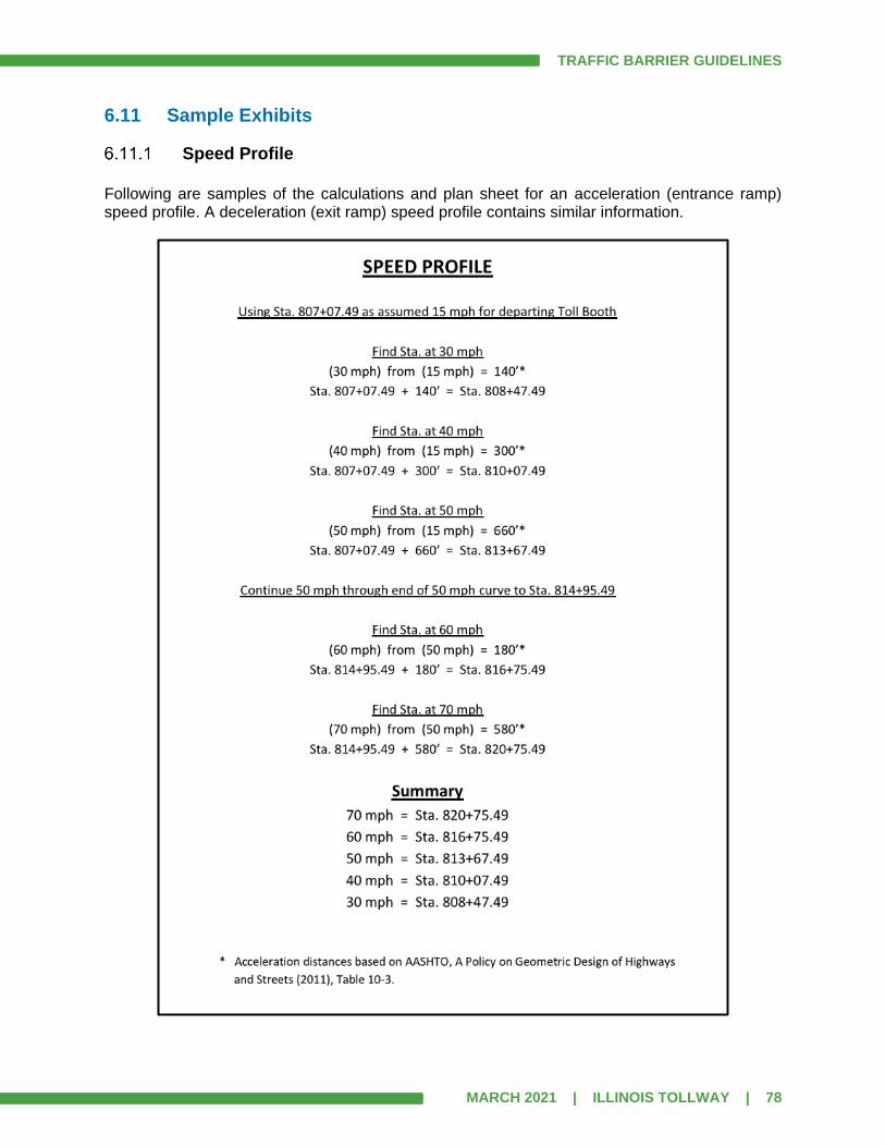
TRAFFIC BARRIER GUIDELINES
MARCH 2021 | ILLINOIS TOLLWAY | 78
6.11 Sample Exhibits
Speed Profile
Following are samples of the calculations and plan sheet for an acceleration (entrance ramp) speed profile. A deceleration (exit ramp) speed profile contains similar information.

TRAFFIC BARRIER GUIDELINES
MARCH 2021 | ILLINOIS TOLLWAY | 79
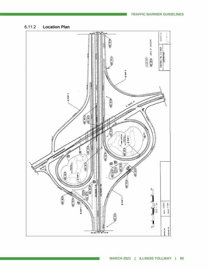
TRAFFIC BARRIER GUIDELINES
MARCH 2021 | ILLINOIS TOLLWAY | 80
Location Plan

TRAFFIC BARRIER GUIDELINES
MARCH 2021 | ILLINOIS TOLLWAY | 81
Level 0 Table
AOC # Station
MP Lt. / Rt.
Existing, Existing to Remain, or Proposed
Description Reason for No Further Action
Remarks
NB–3 3094+53
71.9
Rt. F.S.
Existing to Remain
ComEd Transmission Tower
50’ beyond clear zone
NB-6 3126+21
72.5
Rt. F.S.
Proposed CCTV Camera pole
23’ beyond clear zone
NB-57 3295+17
75.7
Rt. F.S.
Existing to Remain
30” diameter tree
Well beyond clear zone and behind noise wall
NB-58 3300+45
75.8 Rt. F.S.
Proposed Lighting Controller Located well beyond clear zone at ROW fence
NB-72 3369+09
77.1
Rt. F.S.
Existing 40” diameter tree
Tree is near clear zone and will be removed
Rt./Lt. Orientation is based on the direction of traffic F.S. = Foreslope B.S. = Backslope

TRAFFIC BARRIER GUIDELINES
MARCH 2021 | ILLINOIS TOLLWAY | 82
Level 1 Table
AOC # Station
MP Lt. / Rt.
Existing, Existing to Remain, or Proposed
Description Traversable Element? (Note 1)
Recommendations Remarks
NB–13 1294+73
72.5
Rt. F.S.
Existing to Remain
42” dia. Sloped Headwall w/o grate
No Add safety grate Existing grate
missing
NB-16 1322+50
73.0
Rt. F.S.
Existing
15” dia. Concrete slopewall median outlet pipe rusted
out
Yes
Replace w/Ty. III Sloped Headwall Standard B10, 1:4
(V:H)
Replace 10’ of rusted out 15”
CSP. Line existing pipe
NB-27 1322+96
73.0
Rt. F.S.
Existing Concrete Headwall 24” dia. Concrete
Pipe Cross-Culvert No
Replace w/Ty. III Sloped Headwall Standard B10, 1:4
(V:H)
Regrade slope, Realign ditch,
EXTEND PIPE as needed
NB-28 1324+70
73.1 Rt. F.S.
Proposed 4’ x 4’ RCBC with
0 deg skew Yes
Includes pipe runners
Using Standard B13
NB-33 1336+97
73.3
Rt. F.S.
Proposed 42” Headwall Type
III on 1:6 (V:H) foreslope
Yes Includes grate Using Standard
B6
NB-39 1352+80
73.6 Rt. Proposed 24” Headwall Type
III on 1:10 (V:H) transverse slope
Yes Includes grate
Structure faces traffic –
Using Standard B6
NB-99 --
Rt. F.S.
Proposed (numerous locations)
Light Poles Yes All poles have
approved break-away bases
foundations shall be flush with the ground and be
Traversable Elements
NB-98 --
Rt. F.S.
Existing (numerous locations)
Existing Light Poles
No
Remove and replace with LPs that meet current
standard
Poles do not have break-away
devices and/or exist. foundation is too high above
ground
NB-71 Ramp B
4+76
Rt. F.S.
Existing Existing Light Pole No
Relocate LP on new foundation further behind
guardrail
Barrier Clearance Distance was not met for guardrail
NB-41 1379+21
74.1 Rt.
B.S. Proposed
Proposed ground-mounted sign on
1:6 (V:H) foreslope Yes
All posts are break-away
Sign bases are Traversable Elements.
Rt./Lt. Orientation is based on the direction of traffic F.S. = Foreslope B.S. = Backslope
Note 1: See Definitions in Article 1.3. For Existing to Remain elements, if answer is No, then a recommendation is required. If the answer is Yes, then usually there is no proposed work to be done.
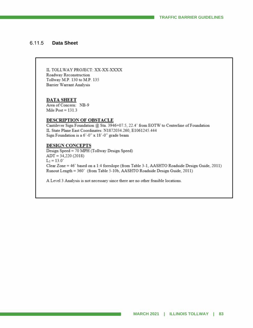
TRAFFIC BARRIER GUIDELINES
MARCH 2021 | ILLINOIS TOLLWAY | 83
Data Sheet

TRAFFIC BARRIER GUIDELINES
MARCH 2021 | ILLINOIS TOLLWAY | 84
Calculation Sheet
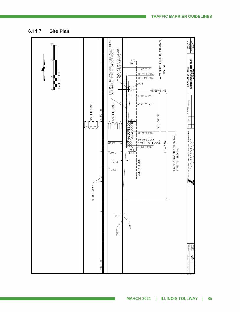
TRAFFIC BARRIER GUIDELINES
MARCH 2021 | ILLINOIS TOLLWAY | 85
Site Plan

TRAFFIC BARRIER GUIDELINES
MARCH 2021 | ILLINOIS TOLLWAY | 86
RSAP Feature Sketch

TRAFFIC BARRIER GUIDELINES
MARCH 2021 | ILLINOIS TOLLWAY | 87
SECTION 7.0 SUBMITTAL SCHEDULE
7.1 Concept Meeting
The concept meeting includes the preparation of an exhibit to be presented to the Illinois Tollway. An overview of the exhibit requirements and the goals of the meeting are described in Article 4.3, Item 3. Barrier warrant exhibits are generally not required for the Concept Plan submittal unless a bridge type study needs to be performed. If a bridge type study is performed, then the procedures and submittal schedule outlined in the Illinois Tollway Structure Design Manual, Article 3.2 shall apply.
7.2 Preliminary Submittal
1. BWA shall be submitted with the Preliminary Plans.
2. Submit a minimum of five sample locations:
A. At least two Level 2.
B. At least two Level 3 with RSAP output and feature sketch.
C. It is recommended that Designer choose locations that may require more review
cycles, are more complex or require extra coordination.
3. Submit one page of the Level 0 Table (at least 4 AOCs).
4. Submit one page of the Level 1 Table (at least 4 AOCs).
5. Submit completed checklist. (This is available on the Illinois Tollway’s WBPM – Project
16).
6. All above materials shall be submitted electronically in PDF format.
7. For projects in e-Builder, a “Barrier Warrant Process” will be spawned automatically with
the Design Milestone Review. The Designer shall complete the required fields within the
process and submit for review. The review does not begin until a complete submittal is
received. The process is closed when review comments are accepted by the Designer.
8. Note that minimum submittal requirements could be reduced for experienced Designers.
This will be decided at the Concept Meeting.
9. Design Project Manager shall verify that the submittal is complete before initiating review
process.
10. If number of review comments is significant, the Designer may be asked to re-submit the
preliminary document.
7.3 Pre-Final Submittal
1. BWA shall be submitted with the Pre-Final Plans.
A. Pre-Final submittal is not complete without BWA.
B. Similar to Pre-Final Plans, the Pre-Final Barrier Warrant shall be considered 100%
complete.
C. Submit Analysis in the Illinois Tollway’s WBPM system separate from the plans.

TRAFFIC BARRIER GUIDELINES
MARCH 2021 | ILLINOIS TOLLWAY | 88
2. All comments on Preliminary Submittal addressed and a disposition of comments
provided within preferred Illinois Tollway, Design Review and Collaboration Platform
(DRCP) software and saved as a PDF document.
3. Submit completed checklist. Check with Illinois Tollway PM for latest version.
4. All above materials shall be submitted electronically in PDF format.
5. For projects in e-Builder, a “Barrier Warrant Process” will be spawned automatically with
the Design Milestone Review. The Designer shall complete the required fields within the
process and submit for review. The review does not begin until a complete submittal is
received. The process is closed when review comments are received by the Designer.
6. Design Project Manager shall verify that the submittal is complete before initiating review
process.
7. Upon completion of the review of the Pre-Final Submittal, a review meeting shall be held
to discuss the review comments.
7.4 Final Submittal
1. Final BWA should be complete at the Final Plan Check.
2. All previous review comments addressed and a disposition of Prefinal comments
provided within the preferred Illinois Tollway, Design Review and Collaboration Platform
(DRCP) software and saved as a PDF document.
3. DSE Final Barrier Warrant shall match the DSE plans submitted for advertisement.
4. Submit completed checklist. Check with Illinois Tollway PM for latest version.
5. All above materials shall be submitted electronically.
6. For projects in e-Builder, the “Barrier Warrant Process” for the Final Submittal will need
to be initialized by the Designer. Unlike the Preliminary and Pre-Final Submittals, it is not
created automatically. The Designer shall complete the required fields within the process
and submit for review. The review does not begin until a complete submittal is received.
The process continues until there are no further comments and the Designer has
uploaded all required documents into e-Builder.
7. Design Project Manager shall verify that the submittal is complete before initiating review
process.
8. Upon completion of the review of the Final Submittal, a review meeting may be
necessary to discuss the review comments.
7.5 No Further Comments – Final Barrier Warrant Analysis
Barrier Warrants are not considered final until there are no further review comments on the Final Submittal. The Illinois Tollway does not approve the final document. For projects outside of e-Builder, when there are no further comments the Designer will receive an email from the Design Project Manager stating that the Barrier Warrant has been reviewed and that there are no further comments.

TRAFFIC BARRIER GUIDELINES
MARCH 2021 | ILLINOIS TOLLWAY | 89
For projects in e-Builder, the final “Barrier Warrant Process” will continue until there are no further comments, when the Process is closed. See Article 7.4. When there are no further comments, the Design Project Manager shall make the Final BWA available to the CM.
7.6 Contracts not requiring a Barrier Warrant Analysis
Contracts in e-Builder
The “Barrier Warrant Process” will be spawned automatically with the Preliminary and Pre-Final Design Milestone Reviews. If no barrier warrant is required, the Designer shall complete the appropriate fields and “cancel/void” the Process. At the Final Plan submittal, the Designer shall initiate the e-Builder “Barrier Warrant Process”, and complete the appropriate fields explaining why the barrier warrant is not required and then “cancel/void” the Process. For contracts where the barrier warrant process was initiated, but due to design development all of the AOCs were determined to be outside of Illinois Tollway jurisdiction, the Designer shall initiate the e-Builder “Barrier Warrant Process” at the Final Plan Submittal, complete the appropriate fields explaining why the barrier warrant is no longer required and “cancel/void” the Process.
Contracts outside e-Builder
Where there is no barrier warrant required, the Designer shall submit a letter to the Illinois Tollway Design PM documenting why none is required. For contracts where the barrier warrant process was initiated, but due to design development all of the AOCs were determined to be outside of Illinois Tollway jurisdiction, the Designer shall submit a letter to the Illinois Tollway Design PM documenting why the process was not completed.
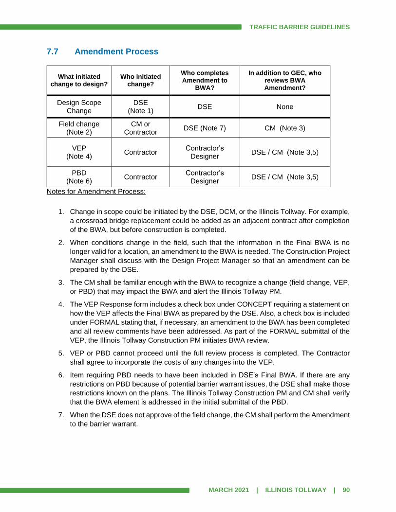
TRAFFIC BARRIER GUIDELINES
MARCH 2021 | ILLINOIS TOLLWAY | 90
7.7 Amendment Process
What initiated change to design?
Who initiated change?
Who completes Amendment to
BWA?
In addition to GEC, who reviews BWA Amendment?
Design Scope Change
DSE (Note 1)
DSE None
Field change (Note 2)
CM or Contractor
DSE (Note 7) CM (Note 3)
VEP (Note 4)
Contractor Contractor’s
Designer DSE / CM (Note 3,5)
PBD (Note 6)
Contractor Contractor’s
Designer DSE / CM (Note 3,5)
Notes for Amendment Process:
1. Change in scope could be initiated by the DSE, DCM, or the Illinois Tollway. For example,
a crossroad bridge replacement could be added as an adjacent contract after completion
of the BWA, but before construction is completed.
2. When conditions change in the field, such that the information in the Final BWA is no
longer valid for a location, an amendment to the BWA is needed. The Construction Project
Manager shall discuss with the Design Project Manager so that an amendment can be
prepared by the DSE.
3. The CM shall be familiar enough with the BWA to recognize a change (field change, VEP,
or PBD) that may impact the BWA and alert the Illinois Tollway PM.
4. The VEP Response form includes a check box under CONCEPT requiring a statement on
how the VEP affects the Final BWA as prepared by the DSE. Also, a check box is included
under FORMAL stating that, if necessary, an amendment to the BWA has been completed
and all review comments have been addressed. As part of the FORMAL submittal of the
VEP, the Illinois Tollway Construction PM initiates BWA review.
5. VEP or PBD cannot proceed until the full review process is completed. The Contractor
shall agree to incorporate the costs of any changes into the VEP.
6. Item requiring PBD needs to have been included in DSE’s Final BWA. If there are any
restrictions on PBD because of potential barrier warrant issues, the DSE shall make those
restrictions known on the plans. The Illinois Tollway Construction PM and CM shall verify
that the BWA element is addressed in the initial submittal of the PBD.
7. When the DSE does not approve of the field change, the CM shall perform the Amendment
to the barrier warrant.

TRAFFIC BARRIER GUIDELINES
MARCH 2021 | ILLINOIS TOLLWAY | 91
SECTION 8.0 GUARDRAIL AND BARRIER TERMINAL USAGE GUIDE – GENERAL
This portion of the manual has been prepared for use in the determination and guidance of placing traffic barriers and their end treatments. The function of a traffic barrier is to shield the motorist from impacting an obstacle along the roadside. All proposed traffic barriers shall conform to the requirements of the current edition of the Illinois Tollway Standard Drawings, Illinois Tollway Recurring Special Provisions, Illinois Department of Transportation Standard Specifications, Illinois Tollway Supplemental Specifications to IDOT Standard Specifications, the AASHTO RDG and Manufacturer’s requirements for proprietary products. Once it has been determined that a longitudinal traffic barrier will be installed, the decision to use guardrail or concrete barrier should be made. Criteria that should be considered in barrier selection include: performance capability, deflection, site conditions (cross slopes and sideslopes), severity of obstacle, compatibility with available end treatments and adjacent barrier systems, cost and maintenance. No modifications to the Illinois Tollway Standard Drawings or Manufacturer’s products shall be permitted.
NCHRP Report 350, Recommended Procedures for the Safety Performance Evaluation of Highway Features, has been the accepted method for safety hardware device testing and acceptance since 1993. AASHTO MASH is an update to and supersedes NCHRP Report 350, for the purposes of evaluating new safety hardware devices. Any new or revised highway safety hardware under development as of October 15, 2009, when the MASH was published, may continue to be tested using the criteria in NCHRP Report 350. However, FHWA will not accept or review requests for new or revised highway safety hardware tested using NCHRP 350 criteria which are received after January 1, 2011.
MASH does not supersede any guidelines for the design of roadside safety hardware, which are contained within the AASHTO RDG. An implementation plan for MASH that was adopted jointly by AASHTO and FHWA states that all highway safety hardware accepted prior to the adoption of MASH – using criteria contained in NCHRP Report 350 – may remain in place and may continue to be manufactured and installed. In addition, highway safety hardware accepted using NCHRP Report 350 criteria is not required to be retested using MASH criteria. However, new highway safety hardware not previously evaluated shall utilize MASH for testing and evaluation. MASH was developed through NCHRP Project 22-14(02), Improvement of Procedures for the Safety-Performance Evaluation of Roadside Features, and contains revised criteria for impact performance evaluation of virtually all highway safety features, based primarily on changes in the vehicle fleet. Crashworthy terminals are the devices used to provide an acceptable level of safety to the upstream end of a roadside barrier or obstacle. An approved crashworthy terminal is a device or system that has been tested according to the requirements contained in NCHRP 350 or MASH (if installed after December 31, 2018).

TRAFFIC BARRIER GUIDELINES
MARCH 2021 | ILLINOIS TOLLWAY | 92
Approved crashworthy traffic barrier terminals meeting MASH TL-3 criteria shall be used on all Illinois Tollway mainline roadways and all ramps and C-D roadways where the design speed is more than 40 mph. TL-2 terminals may be used on Illinois Tollway ramps where the design speed is less than or equal to 40 mph. All guardrail installations and CMBs shall meet TL-3 criteria. The Designer shall conduct a field survey to determine available shoulder width for standard guardrail installation. Additional shoulder widening may be required to meet minimum guardrail embedment requirements based on width and slope of embankment. The Illinois Tollway Standard Drawings for guardrail and for each terminal type show the aggregate shoulder width required behind the posts for proper performance.
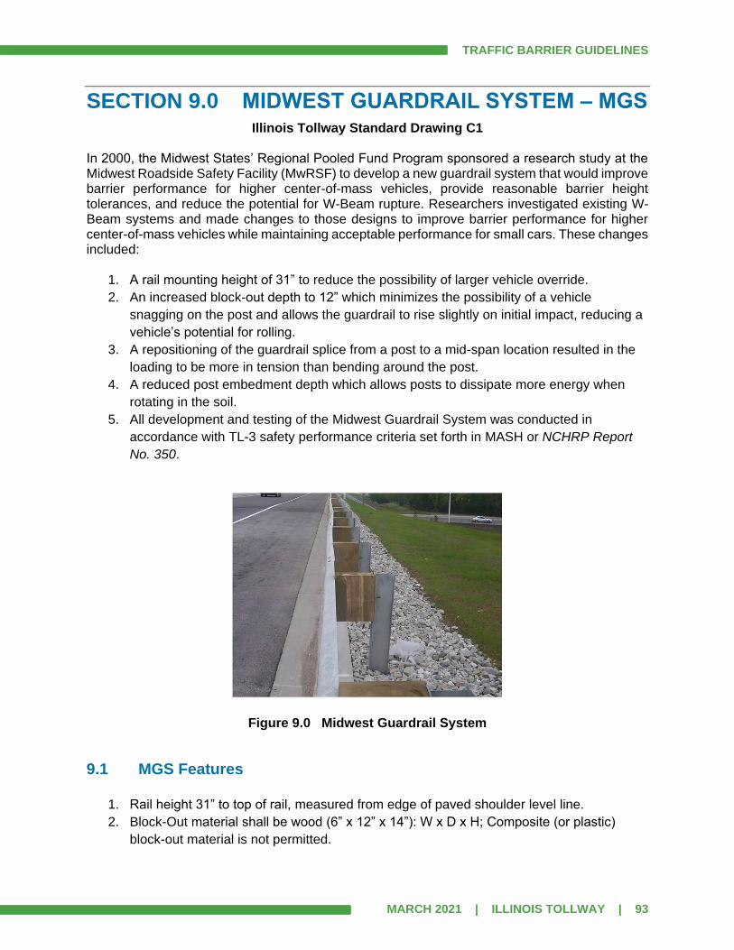
TRAFFIC BARRIER GUIDELINES
MARCH 2021 | ILLINOIS TOLLWAY | 93
SECTION 9.0 MIDWEST GUARDRAIL SYSTEM – MGS Illinois Tollway Standard Drawing C1
In 2000, the Midwest States’ Regional Pooled Fund Program sponsored a research study at the Midwest Roadside Safety Facility (MwRSF) to develop a new guardrail system that would improve barrier performance for higher center-of-mass vehicles, provide reasonable barrier height tolerances, and reduce the potential for W-Beam rupture. Researchers investigated existing W-Beam systems and made changes to those designs to improve barrier performance for higher center-of-mass vehicles while maintaining acceptable performance for small cars. These changes included:
1. A rail mounting height of 31” to reduce the possibility of larger vehicle override.
2. An increased block-out depth to 12” which minimizes the possibility of a vehicle
snagging on the post and allows the guardrail to rise slightly on initial impact, reducing a
vehicle’s potential for rolling.
3. A repositioning of the guardrail splice from a post to a mid-span location resulted in the
loading to be more in tension than bending around the post.
4. A reduced post embedment depth which allows posts to dissipate more energy when
rotating in the soil.
5. All development and testing of the Midwest Guardrail System was conducted in
accordance with TL-3 safety performance criteria set forth in MASH or NCHRP Report
No. 350.
Figure 9.0 Midwest Guardrail System
9.1 MGS Features
1. Rail height 31” to top of rail, measured from edge of paved shoulder level line.
2. Block-Out material shall be wood (6” x 12” x 14”): W x D x H; Composite (or plastic)
block-out material is not permitted.
TRAFFIC BARRIER GUIDELINES
MARCH 2021 | ILLINOIS TOLLWAY | 94
3. Rail element splices are located at mid-span between posts (for Type A installation).
4. All W-Beam guardrail panels shall be lapped in the direction of traffic.
5. Standard post length is 6’-0”.
6. The use of 9’-0” posts is discussed in Articles 9.5 and 9.6. The controlling conditions are
discussed for guardrail installed with and without gutter. Guardrail with 9’ posts uses a
separate pay item and this shall be clearly shown on the design plans.
7. Where gutters, such as Gutter, Type G-2, Type G-2 Modified, Gutter, Type G-3, or Type
G-3 Modified are required in front of the guardrail, the posts shall be located 6” behind
the back of gutter. See Article 9.5.
8. A 1’-0” offset from the edge of paved shoulder to face of rail is typical for guardrail
installed at locations without gutter. See Article 9.6.
9. Standard rail section length is 12’-6” (measured from center of splice to center of splice).
Actual rail length is 13’-6.25” (accounting for overlap). 25’-0” rail sections are not
allowed.
10. Guardrail Type A post spacing is at 6’-3” centers (standard post spacing).
11. Alternate post spacing is used when barrier clearance is less than minimum required for
standard post spacing. See Article 9.2.
A. Guardrail Type B or ½-post spacing is at 3’-1½” centers.
B. Guardrail Type C or ¼-Post spacing is at 1’-6¾” centers.
C. ¼-post spacing requires a transition section of ½-post spacing at the upstream end
of the ¼-post spacing. See Article 9.3.
12. No rail or railing of any type shall be attached to the back of posts.
13. Posts shall be driven free standing into the ground.
14. Posts shall not be attached to any structure by use of welds or mechanical fasteners.
15. Posts shall not be encased in concrete or asphalt. Where posts are to be installed in
pavement areas, leave-outs shall be provided. See Article 9.7 and Illinois Tollway
Standard Drawing C1.
16. Posts shall be steel W6x9 or W6x8.5.
17. Aggregate Shoulders Special, Type C shall be used.
18. See Illinois Tollway Standard Drawing C1 for additional notes and detail.
19. The site preparation for all installations shall be in accordance with current Illinois
Tollway Standard Drawings.

TRAFFIC BARRIER GUIDELINES
MARCH 2021 | ILLINOIS TOLLWAY | 95
9.2 Barrier Clearance Distance
Figure 9.2 Barrier Clearance Distance No rigid object (including light poles and sign supports on breakaway bases) shall be placed within the barrier clearance distance from the back of the barrier system as shown in Figure 9.2. The barrier clearance distance is a horizontal distance measured perpendicular from a line connecting the back of guardrail posts to the nearest point of the obstacle. Table 9.2a shows the minimum clearance distances for different post spacing of the MGS for new construction and reconstruction. Table 9.2b shows the minimum clearance distances for rehabilitation projects. Table 9.2c shows the minimum clearance distances for NCHRP 350 Non-MGS systems.
1. The minimum clearance distance shall be met. However, it is desirable to provide more
than the minimum clearance distance as long as it is economical to do so.
2. Obstacles should be positioned to minimize the use of Type B and Type C post spacing.
3. Temporary storage of material and equipment behind guardrail during construction shall
be placed according to Article 11.4.1 in the Illinois Tollway Roadway Traffic Control and
Communications Manual.
Table 9.2a: Barrier Clearance Distance (MGS)
New Construction/Reconstruction
Guardrail System Post
Spacing Minimum Distance
MGS – 31” Type A 6’- 3” 39”
MGS – 31” Type B ½-Post Spacing
3’- 1½” 34”
MGS – 31” Type C ¼-Post Spacing 1’- 6¾” 26”
OBSTACLE
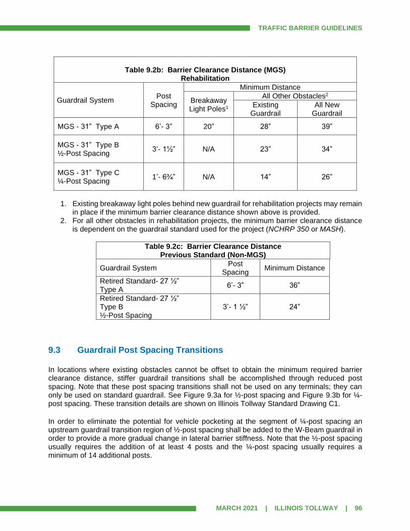
TRAFFIC BARRIER GUIDELINES
MARCH 2021 | ILLINOIS TOLLWAY | 96
Table 9.2b: Barrier Clearance Distance (MGS)
Rehabilitation
Guardrail System Post
Spacing
Minimum Distance
Breakaway Light Poles1
All Other Obstacles2
Existing Guardrail
All New Guardrail
MGS - 31” Type A 6’- 3” 20” 28” 39”
MGS - 31” Type B ½-Post Spacing
3’- 1½” N/A 23” 34”
MGS - 31” Type C ¼-Post Spacing
1’- 6¾” N/A 14” 26”
1. Existing breakaway light poles behind new guardrail for rehabilitation projects may remain
in place if the minimum barrier clearance distance shown above is provided. 2. For all other obstacles in rehabilitation projects, the minimum barrier clearance distance
is dependent on the guardrail standard used for the project (NCHRP 350 or MASH).
Table 9.2c: Barrier Clearance Distance Previous Standard (Non-MGS)
Guardrail System Post
Spacing Minimum Distance
Retired Standard- 27 ½” Type A
6’- 3” 36”
Retired Standard- 27 ½” Type B ½-Post Spacing
3’- 1 ½” 24”
9.3 Guardrail Post Spacing Transitions
In locations where existing obstacles cannot be offset to obtain the minimum required barrier clearance distance, stiffer guardrail transitions shall be accomplished through reduced post spacing. Note that these post spacing transitions shall not be used on any terminals; they can only be used on standard guardrail. See Figure 9.3a for ½-post spacing and Figure 9.3b for ¼-post spacing. These transition details are shown on Illinois Tollway Standard Drawing C1.
In order to eliminate the potential for vehicle pocketing at the segment of ¼-post spacing an upstream guardrail transition region of ½-post spacing shall be added to the W-Beam guardrail in order to provide a more gradual change in lateral barrier stiffness. Note that the ½-post spacing usually requires the addition of at least 4 posts and the ¼-post spacing usually requires a minimum of 14 additional posts.

TRAFFIC BARRIER GUIDELINES
MARCH 2021 | ILLINOIS TOLLWAY | 97
Figure 9.3a Guardrail Post Spacing Transition to ½-Post Spacing
Figure 9.3b Guardrail Post Spacing Transition to ¼-Post Spacing For locations where the ¼-post spacing minimum barrier clearance cannot be met, a single-face concrete barrier shall be installed or the obstacle relocated. Double nesting of the W-Beam rail elements to stiffen the guardrail is not permitted. Extended lengths of ¼-post spacing guardrail are not economical and shall not exceed 100’ without approval of the Illinois Tollway’s Chief Engineering Officer. Because these transitions are not typically paid separately, the locations shall be clearly shown on the design plans.

TRAFFIC BARRIER GUIDELINES
MARCH 2021 | ILLINOIS TOLLWAY | 98
9.4 Omitting a Post for Utility Conflict
For locations where a guardrail post conflicts with a drainage structure, it is permissible to omit a post within a MGS, Type A post spacing, guardrail installation. When a post is omitted within this installation, the minimum distance to an additional omitted post shall be 56’-3”. Also, additional block-outs shall not be added to provide a greater offset, in order for the post to avoid an obstacle. See Figure 9.4 and Illinois Tollway Standard Drawing C1. For Guardrail Type A, which has standard 6’-3” post spacing, omission of a post will create a 12’-6” span. The omitted post tends to increase the deflection distances, so a post cannot be omitted near a traffic barrier terminal. The minimum distances from terminals are stated below. Note that it is not permissible to omit a post from MGS guardrail Type A within a system that is located on, or at the slope break point of a 1:2H fill slope. Where gutter is present in conjunction with MGS guardrail, omission of a post is not permitted. When it is not possible to span guardrail across an underground utility due to the maximum post spacing, the Designer should consider using single-face reinforced concrete barrier instead.
Figure 9.4 Drainage Structure Conflict-Post Spacing (Type A Guardrail)
Omitting of posts in guardrail installations of Guardrail Type B (½-post spacing) and Guardrail Type C (¼-post spacing) shall not be allowed.

TRAFFIC BARRIER GUIDELINES
MARCH 2021 | ILLINOIS TOLLWAY | 99
Altering the standard layout of posts within a Traffic Barrier Terminal (TBT) is not permitted. All posts are necessary to maintain the tested functionality of the traffic barrier terminals. When omitting a post in a guardrail run, the following minimum distances from the end of a traffic barrier terminal (measured to the center of the omitted post) shall be maintained:
1. Traffic barrier terminal Type T1 (Special) or traffic barrier terminal Type T1-A (Special),
the omitted post shall be a minimum distance of 15’-7 ½”.
2. Traffic barrier terminal Type T6 or traffic barrier terminal Type T6B, the omitted post shall
be a minimum distance of 28’-1 ½”.
3. Traffic barrier terminal Type T2, the omitted post shall be a minimum distance of
53’-1½”.
Guardrail post depth shall not be reduced. Designer should attempt to place culverts, sewers and utilities deep enough for guardrail posts to be placed full depth without interference. The Designer should consider using single-face reinforced concrete barrier in the event that the full post depth cannot be achieved.

TRAFFIC BARRIER GUIDELINES
MARCH 2021 | ILLINOIS TOLLWAY | 100
9.5 MGS - Installation with gutter
Figure 9.5 MGS-Guardrail Installation with Gutter
1. Rail height is 31” to top of rail, measured from edge of paved shoulder level line.
(The rail height 24-7/8” is measured from paved surface at edge of shoulder to centerline
of guardrail W-Beam section).
2. Post is set back 6” from the back of gutter.
3. Aggregate shoulder dimension: 3’-0”, measured from back of gutter to shoulder point.
Since there is a considerable contribution to the redirection capability of the system from
the strength of the strong posts, it is necessary to develop adequate soil support for the
post to prevent it from pushing backwards too easily.
A. When the embankment slope 1:S (V:H) and S<3 and the 3’-0” minimum aggregate
shoulder dimension cannot be met, the post length shall be 9’-0”.
B. The minimum aggregate shoulder dimension when 6’-0” posts are used shall be 2’-0”
measured distance from back of post to the shoulder point.
C. The minimum aggregate shoulder dimension when 9’-0” posts are used shall be 1’-0”
measured distance from back of post to the shoulder point.
4. The offset distance from the edge of paved shoulder to face of rail is as follows:
A. 1’-2 ¾” with Gutter, Type G-2 and Type G-2 Modified.
B. 2’-2 ¾” with Gutter, Type G-3 and Type G-3 Modified.
5. Aggregate Shoulders Special, Type C shall be used with guardrail.
When gutter begins/ends within the run of guardrail, a proper transition shall be installed.

TRAFFIC BARRIER GUIDELINES
MARCH 2021 | ILLINOIS TOLLWAY | 101
9.6 MGS - Installation without gutter
Figure 9.6 MGS-Guardrail Installation without Gutter
1. Rail height 31” to top of rail, measured from edge of paved shoulder level line. The rail
height 24-7/8” is measured from paved surface at edge of shoulder to centerline of
guardrail W-Beam section.
2. Distance from edge of paved shoulder to face of rail is 1’-0”.
3. Aggregate shoulder dimension: 4’-0”, measured from edge of paved shoulder to shoulder
point regardless of foreslope and post length. Since there is a considerable contribution
to the redirection capability of the system from the strength of the strong posts, it is
necessary to develop adequate soil support for the post to prevent it from pushing
backwards too easily.
4. When the embankment slope is 1:S (V:H) and S<3, the post length shall be 9’-0”.
5. Aggregate Shoulders Special, Type C shall be used with guardrail.
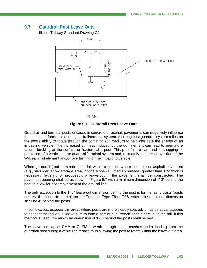
TRAFFIC BARRIER GUIDELINES
MARCH 2021 | ILLINOIS TOLLWAY | 102
9.7 Guardrail Post Leave-Outs
Illinois Tollway Standard Drawing C1
Figure 9.7 Guardrail Post Leave-Outs
Guardrail and terminal posts encased in concrete or asphalt pavements can negatively influence the impact performance of the guardrail/terminal system. A strong post guardrail system relies on the post’s ability to rotate through the confining soil medium to help dissipate the energy of an impacting vehicle. The increased stiffness induced by the confinement can lead to premature failure, buckling at the surface or fracture of a post. This post failure can lead to snagging or pocketing of a vehicle in the guardrail/terminal system and, ultimately, rupture or override of the W-Beam rail element and/or overturning of the impacting vehicle. When guardrail (and terminal) posts fall within a section where concrete or asphalt pavement (e.g., shoulder, snow storage area, bridge slopewall, median surface) greater than 1½“ thick is necessary (existing or proposed), a leave-out in the pavement shall be constructed. The pavement opening shall be as shown in Figure 9.7 with a minimum dimension of 1’-3” behind the post to allow for post movement at the ground line. The only exception to the 1’-3” leave-out dimension behind the post is for the last 6 posts (posts nearest the concrete barrier) on the Terminal Type T6 or T6B, where the minimum dimension shall be 4” behind the posts. In some cases, especially in areas where posts are more closely spaced, it may be advantageous to connect the individual leave-outs to form a continuous “trench” that is parallel to the rail. If this method is used, the minimum dimension of 1’-3” behind the posts shall be met. The leave-out cap of CMA or CLSM is weak enough that it crushes under loading from the guardrail post during a vehicular impact, thus allowing the post to rotate within the leave-out area.
TRAFFIC BARRIER GUIDELINES
MARCH 2021 | ILLINOIS TOLLWAY | 103
9.8 Evaluation of Existing Guardrail
All existing guardrail installations to remain should be analyzed to re-establish the need for a barrier and to verify the need limits. In addition, when alternate design approaches are possible, the use of guardrail shielding shall be demonstrated to be cost-effective and minimized. Existing guardrail which is determined to be warranted shall be evaluated for condition and conformance to current Illinois Tollway Standards for type of rail, post spacing, location, end treatment, height requirements and other similar details. Warranted barriers which are not to the current standard shall be considered for replacement. Although the Illinois Tollway does not allow composite (plastic) block-outs for new installations their presence in an existing run of guardrail does not make the installation substandard, and therefore, shall not be justification for replacement of the guardrail installation. All painted or non-galvanized guardrail shall be considered substandard and replaced with current standard guardrail or terminals. Although the FHWA does not require that the safety appurtenances throughout the Illinois Tollway System be upgraded, the Illinois Tollway has no tort immunity as many governmental agencies do. The Illinois Tollway Risk Management Division works in conjunction with other departments to maintain loss control. Considering these factors and to protect the interests of the Illinois Tollway, it is recommended that all guardrail installations which do not conform to the NCHRP Report 350 be upgraded or programmed to be upgraded to the current Illinois Tollway Standard Drawing. During a major resurfacing or rehabilitation project, these installations shall be replaced with the current system. Because guardrail installations with steel block-outs only meet NCHRP 350 TL-2 criteria, they cannot remain along the mainline or any roadway with a design speed over 40 mph. These installations shall be replaced with the current system. Under no circumstances shall an existing guardrail installation, that was designed using steel block-outs, be extended, attached to or modified in any way from its original design. This includes, but is not limited to rail repair, block-out replacement, terminal upgrade and height adjustment. When an existing run of guardrail that does not meet current standards has to be touched (modified, altered, or adjusted) in any way by the Contractor, Illinois Tollway practice is to remove the existing guardrail and replace it with the current standard guardrail/terminals.
Connecting to Existing Guardrail
If an existing run of guardrail extends past the project limits, it is permissible to connect the current Illinois Tollway standard guardrail (MGS) to an existing guardrail installation that was built using a previous standard if all of the following conditions are met:
1. Existing system meets NCHRP 350, TL-3, and
2. Existing guardrail height is at least 27½”, but no higher than 30½“, and
3. Condition of existing guardrail is acceptable in accordance with Article 9.8, and
4. Remaining length of existing (measured from the project limit) is over 500’ (if existing is
within Illinois Tollway jurisdiction) or 200’ (if another jurisdiction), and
5. Existing installation is programmed for replacement within 5 years, and
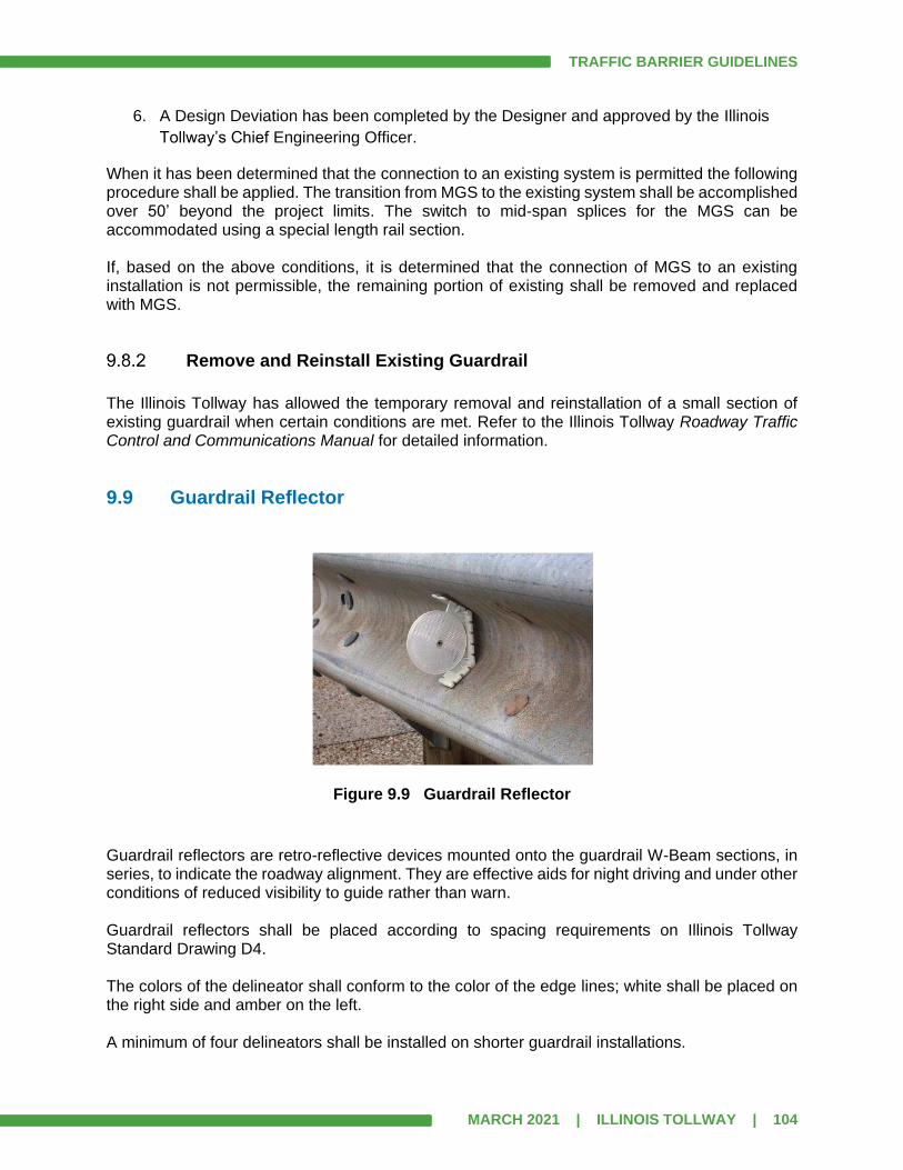
TRAFFIC BARRIER GUIDELINES
MARCH 2021 | ILLINOIS TOLLWAY | 104
6. A Design Deviation has been completed by the Designer and approved by the Illinois
Tollway’s Chief Engineering Officer.
When it has been determined that the connection to an existing system is permitted the following procedure shall be applied. The transition from MGS to the existing system shall be accomplished over 50’ beyond the project limits. The switch to mid-span splices for the MGS can be accommodated using a special length rail section. If, based on the above conditions, it is determined that the connection of MGS to an existing installation is not permissible, the remaining portion of existing shall be removed and replaced with MGS.
Remove and Reinstall Existing Guardrail
The Illinois Tollway has allowed the temporary removal and reinstallation of a small section of existing guardrail when certain conditions are met. Refer to the Illinois Tollway Roadway Traffic Control and Communications Manual for detailed information.
9.9 Guardrail Reflector
Figure 9.9 Guardrail Reflector
Guardrail reflectors are retro-reflective devices mounted onto the guardrail W-Beam sections, in series, to indicate the roadway alignment. They are effective aids for night driving and under other conditions of reduced visibility to guide rather than warn. Guardrail reflectors shall be placed according to spacing requirements on Illinois Tollway Standard Drawing D4. The colors of the delineator shall conform to the color of the edge lines; white shall be placed on the right side and amber on the left. A minimum of four delineators shall be installed on shorter guardrail installations.

TRAFFIC BARRIER GUIDELINES
MARCH 2021 | ILLINOIS TOLLWAY | 105
Mechanically fastened reflectors (metal prong that fits under a head of a bolt) are not permitted on Illinois Tollway guardrail. These act similar to a washer and prevent the proper separation of the rail from the block-out during an impact. Post mounted delineators are to be placed continuously along both mainline and ramps in accordance with Illinois Tollway Standard Drawing D4 in conjunction with guardrail installation.
TRAFFIC BARRIER GUIDELINES
MARCH 2021 | ILLINOIS TOLLWAY | 106
SECTION 10.0 TRAFFIC BARRIER TERMINALS
10.1 General
A TBT shall be attached to each end of a guardrail installation. Each Illinois Tollway terminal is shown in Section C of the Illinois Tollway Standard Drawings and is described in the following articles. Each terminal “anchors” the system and develops the necessary tension in the guardrail to redirect a vehicle after impact. The terminals that the Illinois Tollway uses are divided into upstream and downstream types. Upstream and downstream are based on the direction of traffic (traffic flows downstream) and refer to the ends of the guardrail not the ends of the obstacle. Under no circumstances shall an existing TBT that was designed using a previous standard be relocated, attached to or modified in any way from its original design. If any modification is required and a proper barrier warrant has been completed, the entire barrier installation shall be completely removed and replaced with a new system that conforms to the current standard. Aggregate Shoulders Special, Type C should be used with all guardrail terminals.
10.2 Terminals at Upstream End of Guardrail Installation (General)
The Illinois Tollway typically uses three different terminals at the upstream end of a run of guardrail: Type T1 (Special), Type T1-A (Special) and Type T10. The Type T1 (Special) and Type T1-A (Special) face oncoming traffic and can be hit head-on while the Type T10 is attached to the end of a structure and cannot be hit head-on. Note that the Type T5 terminal is no longer used by the Illinois Tollway.
10.3 Terminals at Upstream End of Guardrail Installation (Facing Traffic)
In addition to providing tension, terminals that face traffic must minimize injury to the vehicle’s occupants when struck head-on.
The terms “gating” and ‘”non-gating” are used to describe characteristics of these systems. See Article 1.3 for definitions. Designers shall assure that these terminals are situated to provide an adequate recovery area behind the terminal. Adequate advance grading, adjacent grading and runout distance grading are critical for achieving optimal crash performance.
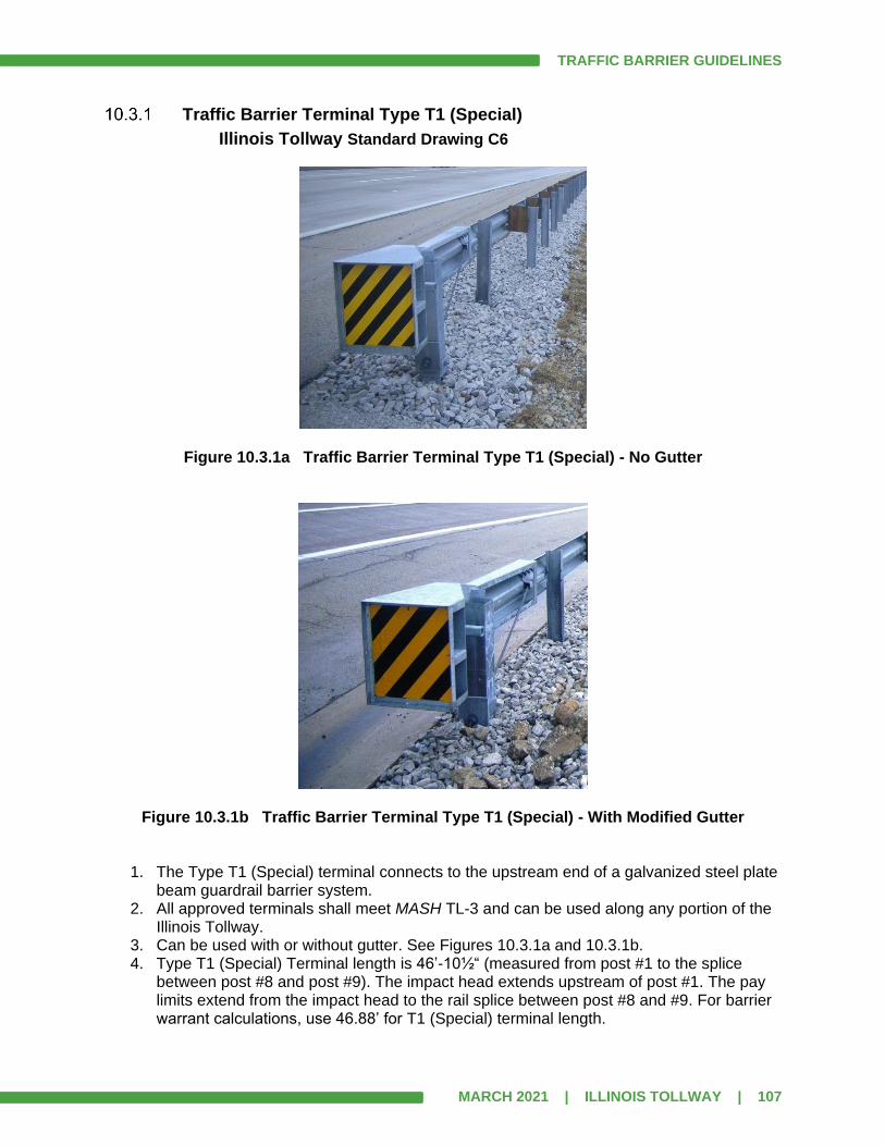
TRAFFIC BARRIER GUIDELINES
MARCH 2021 | ILLINOIS TOLLWAY | 107
Traffic Barrier Terminal Type T1 (Special)
Illinois Tollway Standard Drawing C6
Figure 10.3.1a Traffic Barrier Terminal Type T1 (Special) - No Gutter
Figure 10.3.1b Traffic Barrier Terminal Type T1 (Special) - With Modified Gutter
1. The Type T1 (Special) terminal connects to the upstream end of a galvanized steel plate beam guardrail barrier system.
2. All approved terminals shall meet MASH TL-3 and can be used along any portion of the Illinois Tollway.
3. Can be used with or without gutter. See Figures 10.3.1a and 10.3.1b. 4. Type T1 (Special) Terminal length is 46’-10½“ (measured from post #1 to the splice
between post #8 and post #9). The impact head extends upstream of post #1. The pay limits extend from the impact head to the rail splice between post #8 and #9. For barrier warrant calculations, use 46.88’ for T1 (Special) terminal length.
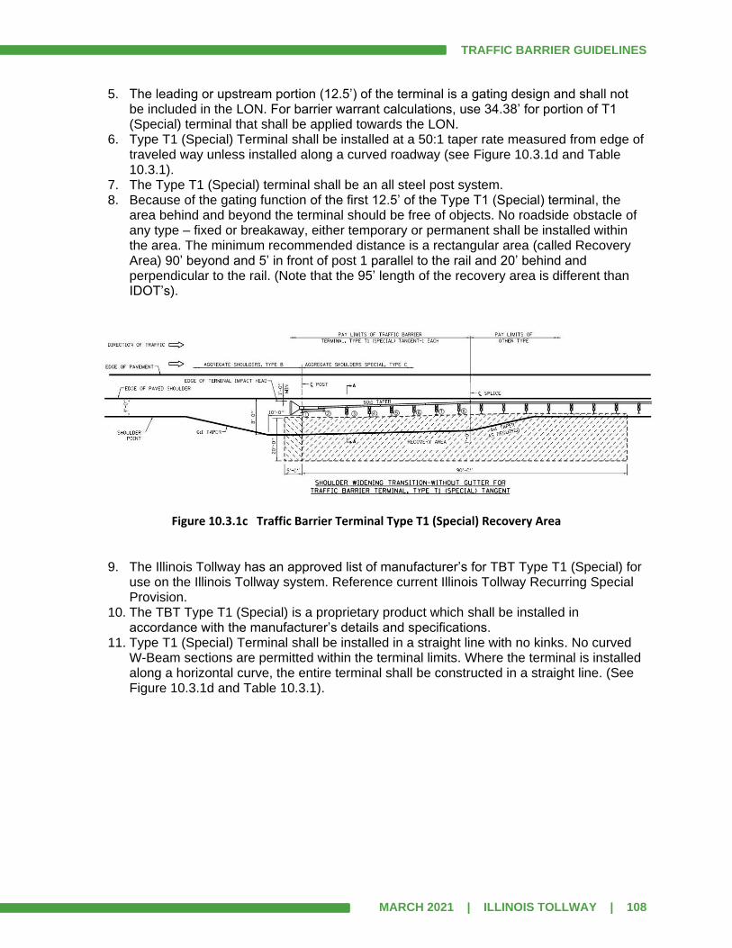
TRAFFIC BARRIER GUIDELINES
MARCH 2021 | ILLINOIS TOLLWAY | 108
5. The leading or upstream portion (12.5’) of the terminal is a gating design and shall not be included in the LON. For barrier warrant calculations, use 34.38’ for portion of T1 (Special) terminal that shall be applied towards the LON.
6. Type T1 (Special) Terminal shall be installed at a 50:1 taper rate measured from edge of traveled way unless installed along a curved roadway (see Figure 10.3.1d and Table 10.3.1).
7. The Type T1 (Special) terminal shall be an all steel post system. 8. Because of the gating function of the first 12.5’ of the Type T1 (Special) terminal, the
area behind and beyond the terminal should be free of objects. No roadside obstacle of any type – fixed or breakaway, either temporary or permanent shall be installed within the area. The minimum recommended distance is a rectangular area (called Recovery Area) 90’ beyond and 5’ in front of post 1 parallel to the rail and 20’ behind and perpendicular to the rail. (Note that the 95’ length of the recovery area is different than IDOT’s).
Figure 10.3.1c Traffic Barrier Terminal Type T1 (Special) Recovery Area
9. The Illinois Tollway has an approved list of manufacturer’s for TBT Type T1 (Special) for use on the Illinois Tollway system. Reference current Illinois Tollway Recurring Special Provision.
10. The TBT Type T1 (Special) is a proprietary product which shall be installed in accordance with the manufacturer’s details and specifications.
11. Type T1 (Special) Terminal shall be installed in a straight line with no kinks. No curved W-Beam sections are permitted within the terminal limits. Where the terminal is installed along a horizontal curve, the entire terminal shall be constructed in a straight line. (See Figure 10.3.1d and Table 10.3.1).
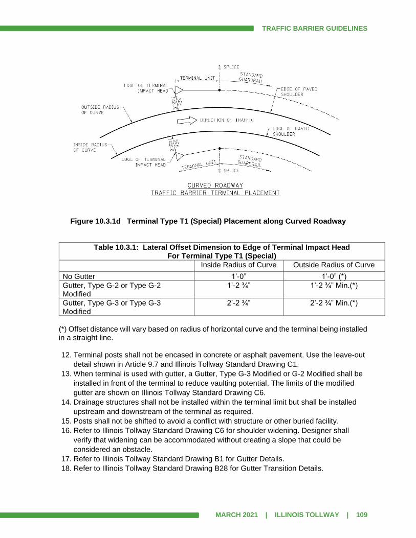
TRAFFIC BARRIER GUIDELINES
MARCH 2021 | ILLINOIS TOLLWAY | 109
Figure 10.3.1d Terminal Type T1 (Special) Placement along Curved Roadway
Table 10.3.1: Lateral Offset Dimension to Edge of Terminal Impact Head For Terminal Type T1 (Special)
Inside Radius of Curve Outside Radius of Curve
No Gutter 1’-0” 1’-0” (*)
Gutter, Type G-2 or Type G-2 Modified
1’-2 ¾” 1’-2 ¾” Min.(*)
Gutter, Type G-3 or Type G-3 Modified
2’-2 ¾” 2’-2 ¾” Min.(*)
(*) Offset distance will vary based on radius of horizontal curve and the terminal being installed in a straight line. 12. Terminal posts shall not be encased in concrete or asphalt pavement. Use the leave-out
detail shown in Article 9.7 and Illinois Tollway Standard Drawing C1.
13. When terminal is used with gutter, a Gutter, Type G-3 Modified or G-2 Modified shall be
installed in front of the terminal to reduce vaulting potential. The limits of the modified
gutter are shown on Illinois Tollway Standard Drawing C6.
14. Drainage structures shall not be installed within the terminal limit but shall be installed
upstream and downstream of the terminal as required.
15. Posts shall not be shifted to avoid a conflict with structure or other buried facility.
16. Refer to Illinois Tollway Standard Drawing C6 for shoulder widening. Designer shall
verify that widening can be accommodated without creating a slope that could be
considered an obstacle.
17. Refer to Illinois Tollway Standard Drawing B1 for Gutter Details.
18. Refer to Illinois Tollway Standard Drawing B28 for Gutter Transition Details.
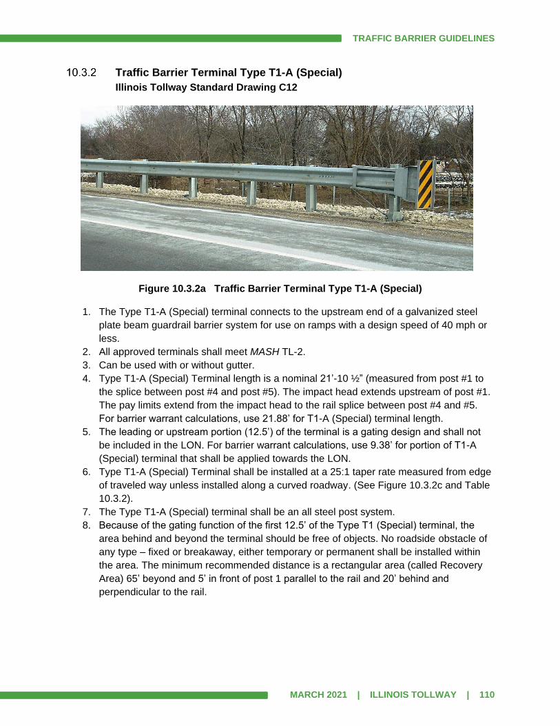
TRAFFIC BARRIER GUIDELINES
MARCH 2021 | ILLINOIS TOLLWAY | 110
Traffic Barrier Terminal Type T1-A (Special)
Illinois Tollway Standard Drawing C12
Figure 10.3.2a Traffic Barrier Terminal Type T1-A (Special) 1. The Type T1-A (Special) terminal connects to the upstream end of a galvanized steel
plate beam guardrail barrier system for use on ramps with a design speed of 40 mph or
less.
2. All approved terminals shall meet MASH TL-2.
3. Can be used with or without gutter.
4. Type T1-A (Special) Terminal length is a nominal 21’-10 ½” (measured from post #1 to
the splice between post #4 and post #5). The impact head extends upstream of post #1.
The pay limits extend from the impact head to the rail splice between post #4 and #5.
For barrier warrant calculations, use 21.88’ for T1-A (Special) terminal length.
5. The leading or upstream portion (12.5’) of the terminal is a gating design and shall not
be included in the LON. For barrier warrant calculations, use 9.38’ for portion of T1-A
(Special) terminal that shall be applied towards the LON.
6. Type T1-A (Special) Terminal shall be installed at a 25:1 taper rate measured from edge
of traveled way unless installed along a curved roadway. (See Figure 10.3.2c and Table
10.3.2).
7. The Type T1-A (Special) terminal shall be an all steel post system.
8. Because of the gating function of the first 12.5’ of the Type T1 (Special) terminal, the
area behind and beyond the terminal should be free of objects. No roadside obstacle of
any type – fixed or breakaway, either temporary or permanent shall be installed within
the area. The minimum recommended distance is a rectangular area (called Recovery
Area) 65’ beyond and 5’ in front of post 1 parallel to the rail and 20’ behind and
perpendicular to the rail.
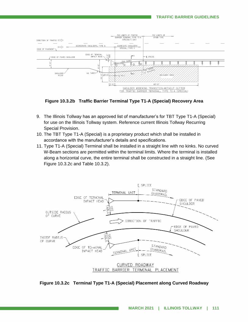
TRAFFIC BARRIER GUIDELINES
MARCH 2021 | ILLINOIS TOLLWAY | 111
Figure 10.3.2b Traffic Barrier Terminal Type T1-A (Special) Recovery Area
9. The Illinois Tollway has an approved list of manufacturer’s for TBT Type T1-A (Special)
for use on the Illinois Tollway system. Reference current Illinois Tollway Recurring
Special Provision.
10. The TBT Type T1-A (Special) is a proprietary product which shall be installed in
accordance with the manufacturer’s details and specifications.
11. Type T1-A (Special) Terminal shall be installed in a straight line with no kinks. No curved
W-Beam sections are permitted within the terminal limits. Where the terminal is installed
along a horizontal curve, the entire terminal shall be constructed in a straight line. (See
Figure 10.3.2c and Table 10.3.2).
Figure 10.3.2c Terminal Type T1-A (Special) Placement along Curved Roadway
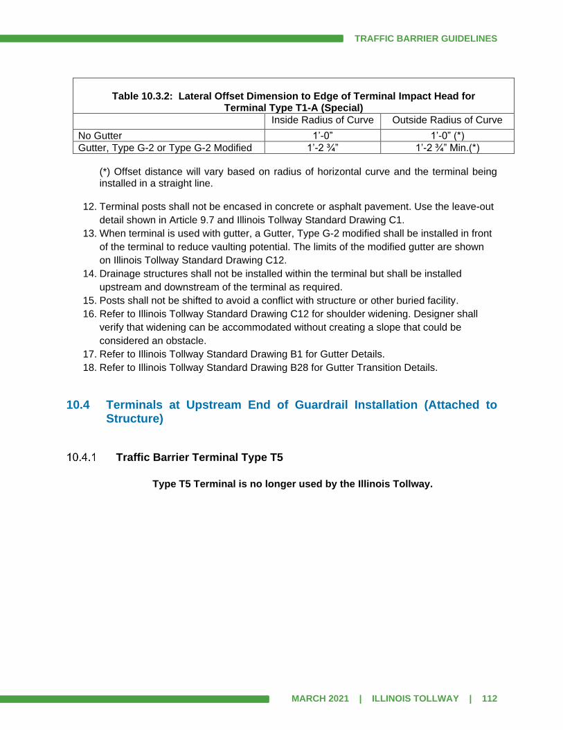
TRAFFIC BARRIER GUIDELINES
MARCH 2021 | ILLINOIS TOLLWAY | 112
Table 10.3.2: Lateral Offset Dimension to Edge of Terminal Impact Head for
Terminal Type T1-A (Special)
Inside Radius of Curve Outside Radius of Curve
No Gutter 1’-0” 1’-0” (*)
Gutter, Type G-2 or Type G-2 Modified 1’-2 ¾” 1’-2 ¾” Min.(*)
(*) Offset distance will vary based on radius of horizontal curve and the terminal being installed in a straight line.
12. Terminal posts shall not be encased in concrete or asphalt pavement. Use the leave-out
detail shown in Article 9.7 and Illinois Tollway Standard Drawing C1.
13. When terminal is used with gutter, a Gutter, Type G-2 modified shall be installed in front
of the terminal to reduce vaulting potential. The limits of the modified gutter are shown
on Illinois Tollway Standard Drawing C12.
14. Drainage structures shall not be installed within the terminal but shall be installed
upstream and downstream of the terminal as required.
15. Posts shall not be shifted to avoid a conflict with structure or other buried facility.
16. Refer to Illinois Tollway Standard Drawing C12 for shoulder widening. Designer shall
verify that widening can be accommodated without creating a slope that could be
considered an obstacle.
17. Refer to Illinois Tollway Standard Drawing B1 for Gutter Details.
18. Refer to Illinois Tollway Standard Drawing B28 for Gutter Transition Details.
10.4 Terminals at Upstream End of Guardrail Installation (Attached to Structure)
Traffic Barrier Terminal Type T5
Type T5 Terminal is no longer used by the Illinois Tollway.
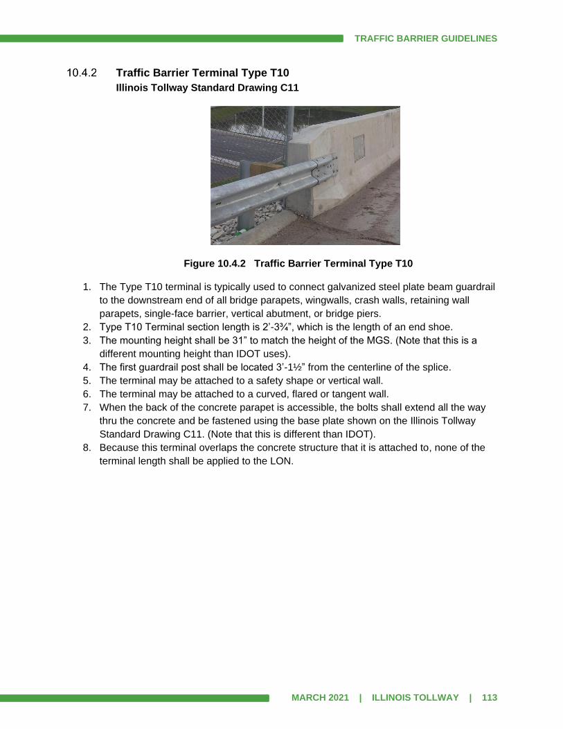
TRAFFIC BARRIER GUIDELINES
MARCH 2021 | ILLINOIS TOLLWAY | 113
Traffic Barrier Terminal Type T10
Illinois Tollway Standard Drawing C11
Figure 10.4.2 Traffic Barrier Terminal Type T10
1. The Type T10 terminal is typically used to connect galvanized steel plate beam guardrail
to the downstream end of all bridge parapets, wingwalls, crash walls, retaining wall
parapets, single-face barrier, vertical abutment, or bridge piers.
2. Type T10 Terminal section length is 2’-3¾”, which is the length of an end shoe.
3. The mounting height shall be 31” to match the height of the MGS. (Note that this is a
different mounting height than IDOT uses).
4. The first guardrail post shall be located 3’-1½” from the centerline of the splice.
5. The terminal may be attached to a safety shape or vertical wall.
6. The terminal may be attached to a curved, flared or tangent wall.
7. When the back of the concrete parapet is accessible, the bolts shall extend all the way
thru the concrete and be fastened using the base plate shown on the Illinois Tollway
Standard Drawing C11. (Note that this is different than IDOT).
8. Because this terminal overlaps the concrete structure that it is attached to, none of the
terminal length shall be applied to the LON.
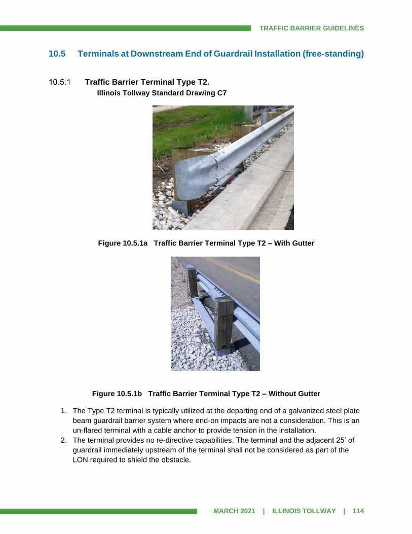
TRAFFIC BARRIER GUIDELINES
MARCH 2021 | ILLINOIS TOLLWAY | 114
10.5 Terminals at Downstream End of Guardrail Installation (free-standing)
Traffic Barrier Terminal Type T2.
Illinois Tollway Standard Drawing C7
Figure 10.5.1a Traffic Barrier Terminal Type T2 – With Gutter
Figure 10.5.1b Traffic Barrier Terminal Type T2 – Without Gutter
1. The Type T2 terminal is typically utilized at the departing end of a galvanized steel plate
beam guardrail barrier system where end-on impacts are not a consideration. This is an
un-flared terminal with a cable anchor to provide tension in the installation.
2. The terminal provides no re-directive capabilities. The terminal and the adjacent 25’ of
guardrail immediately upstream of the terminal shall not be considered as part of the
LON required to shield the obstacle.
TRAFFIC BARRIER GUIDELINES
MARCH 2021 | ILLINOIS TOLLWAY | 115
3. There are two installation details, with or without a gutter system. When the terminal is
used with a gutter, the two wood posts require 12” block-outs. Block-Outs shall not be
used when gutter is not present.
4. Type T2 Terminal total length is 13’-3¼” (12’-6” measured from last guardrail post to last
terminal post).
5. Terminal posts shall be wood and shall not be encased in concrete or asphalt pavement.
Use the leave-out detail shown in Article 9.7 and Illinois Tollway Standard Drawing C1.
6. The top of the steel tube and top of the strut shall be nearly level with the ground. Upon
impact the remaining hardware shall meet the requirements of Figure 3.4.1 (Breakaway
Clearance Diagram).
7. A rigid obstacle should not be placed immediately adjacent to the upstream end of a
Type T2 terminal because of the potential for increased deflection of the guardrail just
upstream of the terminal. See Figure 5.14.
10.6 Terminals at Downstream End of Guardrail Installation (attached to structure)
If the existing parapet on the approach side of a bridge is curved on the roadway side, the preferred option is to straighten the parapet and attached either a Type T6 (with gutter) or a Type T6B (without gutter). If an existing slope drain inlet and curb are located behind the existing terminal, it can be difficult to properly install either a Type T6 or a Type T6B terminal on the approach to a structure during a rehabilitation project. When this occurs the preferred option is to remove the curb and inlet, install new gutter from the bridge (with proper gutter transition) to a new drainage structure outside the terminal limits, install a new drainage structure and outlet, and install a new Terminal Type T6. If the existing slope drain and curb are set back from the guardrail terminal posts another option is to leave the curb and inlet in place, and install a new Terminal Type T6B (with proper leave-outs around the posts).
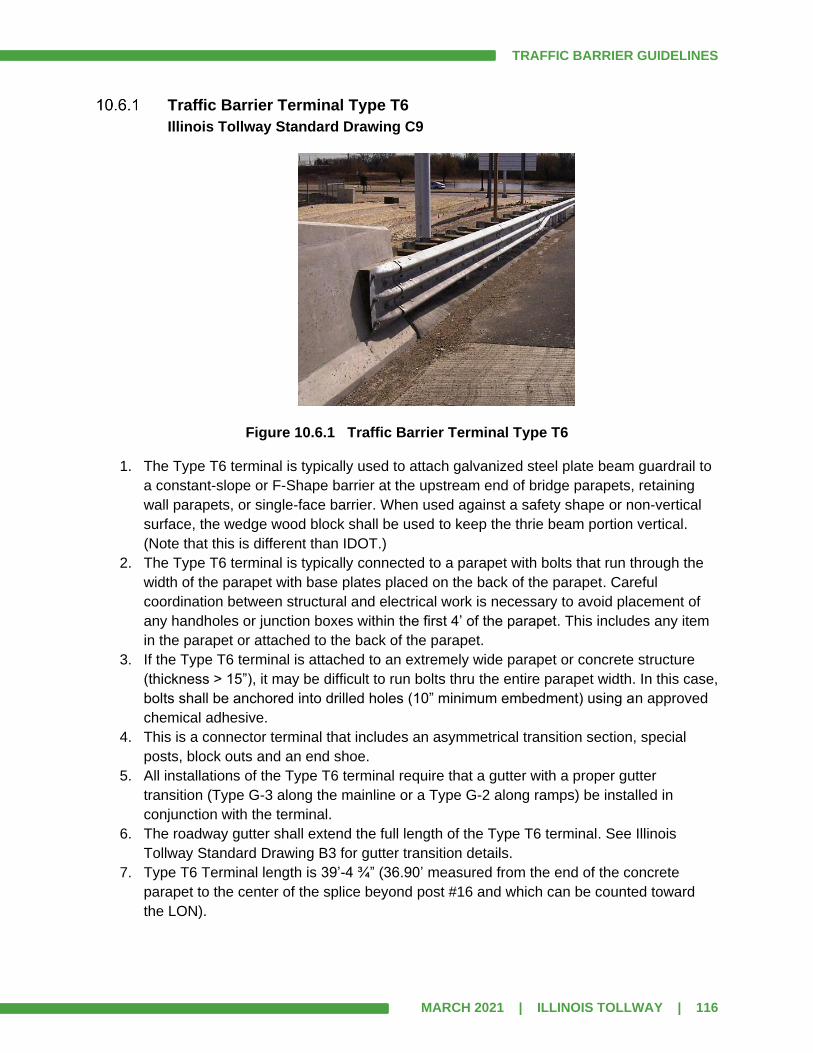
TRAFFIC BARRIER GUIDELINES
MARCH 2021 | ILLINOIS TOLLWAY | 116
Traffic Barrier Terminal Type T6
Illinois Tollway Standard Drawing C9
Figure 10.6.1 Traffic Barrier Terminal Type T6
1. The Type T6 terminal is typically used to attach galvanized steel plate beam guardrail to
a constant-slope or F-Shape barrier at the upstream end of bridge parapets, retaining
wall parapets, or single-face barrier. When used against a safety shape or non-vertical
surface, the wedge wood block shall be used to keep the thrie beam portion vertical.
(Note that this is different than IDOT.)
2. The Type T6 terminal is typically connected to a parapet with bolts that run through the
width of the parapet with base plates placed on the back of the parapet. Careful
coordination between structural and electrical work is necessary to avoid placement of
any handholes or junction boxes within the first 4’ of the parapet. This includes any item
in the parapet or attached to the back of the parapet.
3. If the Type T6 terminal is attached to an extremely wide parapet or concrete structure
(thickness > 15”), it may be difficult to run bolts thru the entire parapet width. In this case,
bolts shall be anchored into drilled holes (10” minimum embedment) using an approved
chemical adhesive.
4. This is a connector terminal that includes an asymmetrical transition section, special
posts, block outs and an end shoe.
5. All installations of the Type T6 terminal require that a gutter with a proper gutter
transition (Type G-3 along the mainline or a Type G-2 along ramps) be installed in
conjunction with the terminal.
6. The roadway gutter shall extend the full length of the Type T6 terminal. See Illinois
Tollway Standard Drawing B3 for gutter transition details.
7. Type T6 Terminal length is 39’-4 ¾” (36.90’ measured from the end of the concrete
parapet to the center of the splice beyond post #16 and which can be counted toward
the LON).
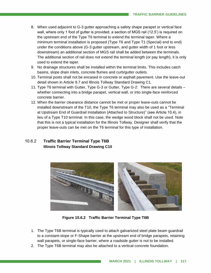
TRAFFIC BARRIER GUIDELINES
MARCH 2021 | ILLINOIS TOLLWAY | 117
8. When used adjacent to G-3 gutter approaching a safety shape parapet or vertical face
wall, where only 1 foot of gutter is provided, a section of MGS rail (12.5’) is required on
the upstream end of the Type T6 terminal to extend the terminal taper. Where a
minimum terminal installation is proposed (Type T6 and Type T1 (Special) end to end)
under the conditions above (G-3 gutter upstream, and gutter width of 1 foot or less
downstream) an additional section of MGS rail shall be added between the terminals.
The additional section of rail does not extend the terminal length (or pay length), it is only
used to extend the taper.
9. No drainage structures shall be installed within the terminal limits. This includes catch
basins, slope drain inlets, concrete flumes and curb/gutter outlets.
10. Terminal posts shall not be encased in concrete or asphalt pavement. Use the leave-out
detail shown in Article 9.7 and Illinois Tollway Standard Drawing C1.
11. Type T6 terminal with Gutter, Type G-3 or Gutter, Type G-2: There are several details –
whether connecting into a bridge parapet, vertical wall, or into single-face reinforced
concrete barrier.
12. When the barrier clearance distance cannot be met or proper leave-outs cannot be
installed downstream of the T10, the Type T6 terminal may also be used as a “Terminal
at Upstream End of Guardrail Installation (Attached to Structure)” (see Article 10.4), in
lieu of a Type T10 terminal. In this case, the wedge wood block shall not be used. Note
that this is not a typical installation for the Illinois Tollway. Designer shall verify that the
proper leave-outs can be met on the T6 terminal for this type of installation.
Traffic Barrier Terminal Type T6B
Illinois Tollway Standard Drawing C10
Figure 10.6.2 Traffic Barrier Terminal Type T6B
1. The Type T6B terminal is typically used to attach galvanized steel plate beam guardrail
to a constant-slope or F-Shape barrier at the upstream end of bridge parapets, retaining
wall parapets, or single-face barrier, where a roadside gutter is not to be installed.
2. The Type T6B terminal may also be attached to a vertical concrete foundation.

TRAFFIC BARRIER GUIDELINES
MARCH 2021 | ILLINOIS TOLLWAY | 118
3. This is a connector terminal similar to the Type T6 that includes an asymmetrical
transition section, special posts, block outs and an end shoe.
4. It requires blocking out the thrie beam rail of the transition by 8” at the connection point.
The Designer shall carefully weigh the relative merits of this potential loss of horizontal
clearance against the complications of adding a gutter transition when selecting between
the Type T6B terminal and the Type T6 for attachment to a structure.
5. Roadway profile and drainage issues should be carefully studied to ensure water runoff
around the end of the parapet will not adversely affect the aggregate shoulder material,
terminal post installations, or the embankment.
6. When roadway water runoff drains towards this type of terminal (opposite to the direction
of traffic) along a bridge parapet or retaining wall, the TBT Type T6 with gutter should be
installed.
7. Type T6B Terminal length is 51’-10 ¾” (36.90’ measured from the end of the concrete
parapet to the center of splice beyond post #16 and which shall be counted toward the
LON).
8. When the terminal is used against a safety shape the wood block-outs shall be tapered
so that the thrie beam portion of the terminal remains vertical.
9. When the terminal is used against a vertical face, the wood block-outs shall not be
tapered. The top and bottom of the rail element shall be the same distance from the
concrete vertical face.
10. Terminal posts shall not be encased in concrete or asphalt pavement. Use the leave-out
detail shown in Article 9.7 and Illinois Tollway Standard Drawing C1.

TRAFFIC BARRIER GUIDELINES
MARCH 2021 | ILLINOIS TOLLWAY | 119
SECTION 11.0 IMPACT ATTENUATORS
Impact attenuators are protective systems that prevent errant vehicles from impacting rigid obstacles by either decelerating the vehicle to a stop after a frontal impact or by redirecting it away from the obstacle after a side impact. Impact attenuators are adaptable to many roadside locations where longitudinal barriers cannot practically be used.
The Illinois Tollway requires that all permanent impact attenuators pass MASH TL-3 testing criteria. Each unit is proprietary and the installation shall follow manufacturer’s requirements including any base or pad. The Designer shall show the width of the obstacle to be shielded by the impact attenuator. The full length of the impact attenuator is considered re-directive and therefore shall count toward the LON. Note that this is for TL-3 shielding only.
11.1 Energy Absorbing Devices
The approach ends of permanent blunt obstacles, such as concrete barriers within the clear zone, shall be shielded. Concrete barrier ends are usually shielded with a TBT and guardrail system, but the use of an impact attenuator should be investigated. At median emergency turnarounds and gores, it may not be possible to install a guardrail system. In those locations, an impact attenuator may be appropriate.
Impact attenuators operate on the principle of absorbing the energy of the vehicle through collapsible bays and mechanical resistance to slow the impacting vehicle. Some energy is also absorbed by the vehicle as the front end of the vehicle is crushed on impact. Some impact attenuators of this type require a rigid back-up support to contain the forces created by the deformation of the device. Most devices of this type capture the vehicle in a frontal impact. For side impacts, the vehicle is smoothly redirected by means of side panels and/or cables. Vertical and lateral restraint of the device is also required. Because of procurement and stocking of additional parts by Illinois Tollway Maintenance, the Designer should always try to use the standard width unit. Accordingly, the use of a wide impact attenuator needs approval from Illinois Tollway Maintenance.
The following products are approved energy absorbing impact attenuators for use on the Illinois Tollway system:
• The SCI100GM Smart Cushion, by Work Area Protection Corporation
• Other MASH attenuators with FHWA Eligibility Letters and meeting the requirements of
the Illinois Tollway specifications may be considered

TRAFFIC BARRIER GUIDELINES
MARCH 2021 | ILLINOIS TOLLWAY | 120
SCI Smart Cushion
Figure 11.1.1a SCI100GM Smart Cushion
The SCI Smart Cushion is a bi-directional, re-directive, non-gating impact attenuator/end treatment for obstacles likely to be struck head-on. Its narrow width allows it to be utilized for narrow site obstacles such as median emergency turnarounds, toll plazas (mainline cash side for manned booths or adjacent to I-Pass only lanes on system ramps) or a concrete/guardrail barrier end treatment.
Figures 11.1.1b Median Emergency Turnaround The SCI100GM Smart Cushion system utilizes a cable and cylinder assembly surrounded by a rigid framework and galvanized steel side panels. During head-on impacts the reverse-tapered design collapses along the front sled supported by rollers. The attenuator uses hydraulic porting to ensure that the proper resistance is used to stop the vehicle before it reaches the end of the cushion’s usable length. The system must be anchored onto a concrete pad. Foundations must be installed according to the manufacturer’s recommendations. The cross slope of the concrete pad shall be 1:10 or less. An impact attenuator shall not be installed over drainage basins or expansion joints. The Smart Cushion can attach to two separate runs of guardrail, such as at a gore. This installation requires an asymmetrical transition piece to connect the SCI100GM to the MGS W-Beam guardrail.

TRAFFIC BARRIER GUIDELINES
MARCH 2021 | ILLINOIS TOLLWAY | 121
The Smart Cushion is a proprietary product by Work Area Protection Corporation. The installation shall be in accordance with manufacturer’s requirements.
Policy for Upgrading of Permanent Impact Attenuators
1. During a rehabilitation project, the DSE shall inventory all existing impact attenuators
and determine the unit type. Manufacturer’s representatives are available to assist in this
determination.
2. Those units that do not meet the current standard shall be removed and replaced. The
current standard unit is a SCI100GM by Work Area Protection Corporation. Note that the
new unit length could be different than an existing attenuator.
3. Attenuator units that were tested and approved under NCHRP Report 350 were primarily
used as end treatment for concrete barriers. These units shall be removed, if they are
beyond repair, and replaced with a current standard energy attenuator unit.
4. Sometimes attenuator units need to be removed and reinstalled. Existing Smart Cushion
units can remain, if in good condition.
5. If the elevation of the pad has to be raised because of an overlay, the existing pad may
remain and be overlaid. However, special longer anchors would be required.
6. If the elevation of the pad is raised at a unit that uses a concrete backup or shields the
blunt end of a concrete barrier, then the Designer shall verify that the concrete is tall
enough for a proper connection.
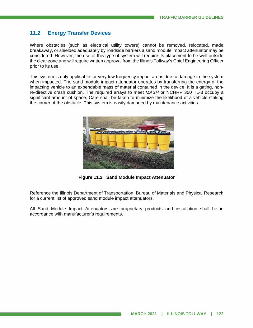
TRAFFIC BARRIER GUIDELINES
MARCH 2021 | ILLINOIS TOLLWAY | 122
11.2 Energy Transfer Devices
Where obstacles (such as electrical utility towers) cannot be removed, relocated, made breakaway, or shielded adequately by roadside barriers a sand module impact attenuator may be considered. However, the use of this type of system will require its placement to be well outside the clear zone and will require written approval from the Illinois Tollway’s Chief Engineering Officer prior to its use. This system is only applicable for very low frequency impact areas due to damage to the system when impacted. The sand module impact attenuator operates by transferring the energy of the impacting vehicle to an expendable mass of material contained in the device. It is a gating, non-re-directive crash cushion. The required arrays to meet MASH or NCHRP 350 TL-3 occupy a significant amount of space. Care shall be taken to minimize the likelihood of a vehicle striking the corner of the obstacle. This system is easily damaged by maintenance activities.
Figure 11.2 Sand Module Impact Attenuator Reference the Illinois Department of Transportation, Bureau of Materials and Physical Research for a current list of approved sand module impact attenuators. All Sand Module Impact Attenuators are proprietary products and installation shall be in accordance with manufacturer’s requirements.

TRAFFIC BARRIER GUIDELINES
MARCH 2021 | ILLINOIS TOLLWAY | 123
SECTION 12.0 HIGH-TENSION CABLE MEDIAN BARRIER
High tension cable median barriers (CMB) are adaptable traffic devices suited for use in existing medians to prevent cross-over crashes. Current Illinois Tollway practice has been to systematically install CMB to fill-in all open medians or other locations where a vehicle could potentially cross into on-coming traffic.
Figure 12.0 Cable Median Barrier High-Tension CMB consists of three or four steel cables supported by weak posts. During installation, the cables are placed on the posts and then tightened to a specific tension, according to temperature. All high-tension systems are proprietary products and installation shall be in accordance with manufacturer’s requirements and cannot be mixed. High-Tension cable barrier cannot be installed within a range of 1’ to 8’ from the bottom of a median ditch according to FHWA standards. Because deflection distances observed in the field exceed those cited in the NCHRP crash test results, the CMB shall not be placed closer than 12’ from any rigid object including breakaway devices and guardrail. Per Illinois Tollway Special Provisions, the manufacturer is required to design the TL-3 system to provide a maximum deflection of 8.5’. High-Tension CMB shall not be placed on slopes steeper than 1:4 (V:H). When using on 1:4 (V:H) slopes, the manufacturers’ have specific requirements that shall be followed. Other layout considerations include:
1. Excessive continuous lengths of cable barrier should be avoided. Continuous
installations should be less than 2600’ in length.

TRAFFIC BARRIER GUIDELINES
MARCH 2021 | ILLINOIS TOLLWAY | 124
2. Desirable minimum length of installation should be 200’ and absolute minimum shall be
100’ (not counting terminals).
3. Installations should be positioned to minimize the gap between runs at emergency
turnaround locations.
4. CMB or its terminals shall not be placed in front of guardrail or within the recovery area
of a T1 (Special) or a T1-A (Special) terminal.
5. When installed along horizontal curves, the CMB shall be placed on the side least likely
to be contacted by an errant vehicle (near the traffic making a left-hand turn).
6. Where one roadway is on a separate, significantly higher profile, the CMB shall be
placed along the higher roadway.
7. When CMB switches sides of the median, the overlap shall be based on a 25-degree
departure angle from the travel way of each side.
8. Where the ends of the CMB terminate, the Lengths of Need of adjacent systems shall
overlap, to form a continuous line of CMB.
9. CMB shall not be used as the only shielding for any Level 2 obstacle.

TRAFFIC BARRIER GUIDELINES
MARCH 2021 | ILLINOIS TOLLWAY | 125
SECTION 13.0 CONCRETE BARRIER Safety shape barriers are designed to dissipate the energy of crash impacts. Constant-Slope concrete barriers maintain a near vertical slope face for its entire height. The overall height is 44” above grade when used as a TL-4 or TL-5 barrier. When a vehicle impacts a constant-slope barrier, a portion of its energy is absorbed in the climbing or lifting action that occurs when the tires roll up the sloping face. During resurfacing operations, the uniform slope of the concrete barrier means that the barrier performs consistently, even after an overlay. In medium speed impacts there is likely to be damage to the vehicle, but the force experienced by the occupants will be minimized. In higher speed impacts there will be significant vehicle damage and minor to moderate injury potential to the occupants. The constant-slope barrier uses a battered face and was originally conceived to be utilized as temporary concrete barrier. Other near vertical, constant-slope barriers have been developed and used around the country, most often they have a slope between 9-degrees and 11-degrees from vertical. The Illinois Tollway uses the constant-slope safety shape for parapets on bridges, retaining walls and moment slabs; and for concrete median barriers and roadside barriers. The concrete median barrier and roadside barriers are described below and the parapets are described in the Illinois Tollway Structure Design Manual. The Illinois Tollway uses a 72” tall concrete parapet/barrier when combined with a structure-mounted noise abatement wall. The noise abatement wall is mounted to, and behind the parapet. When the 72” barrier and NAW combination is used, the full-height barrier shall extend for a minimum distance of 10’ on the traffic approach end of the NAW. The upstream end of the 72” parapet/barrier and noise abatement wall shall be shielded as part of a barrier warrant analysis. The minimum allowable height for a TL-4 barrier is 32” during resurfacing operations or for rehabilitation projects. The minimum allowable height for a TL-5 barrier left in place, is 42” for resurfacing and rehabilitation projects. When transitioning from a barrier of lower height to a taller height, the height transition shall taper at 1V:10H or flatter in the direction of traffic. Concrete barrier should be considered as an alternative to shield rigid objects where no deflection distance is available or where crash frequency is expected to be higher than normal. Concrete barrier should be used, in lieu of guardrail, when a higher test level is desired due to the severity of an obstacle. Gutter, Types G-3 or G-2 shall not be placed in front of concrete barrier. The concrete barriers either have a 2’ wide gutter incorporated into the barrier base on the traffic side or have a theoretical 2’ wide gutter as part of the moment slab configuration along the traffic face. When the concrete barrier tapers toward the roadway as it proceeds downstream, the taper rate shall not exceed the suggested rates in AASHTO RDG Table 5-9 for rigid barrier. The taper rate is dependent on whether or not the barrier offset from the EOTW is greater than or less than the shy line offset. Junction boxes shall be flush-mounted at the top of median barrier and surface-mounted to the back side of single-face reinforced concrete barrier when not accessible to traffic.
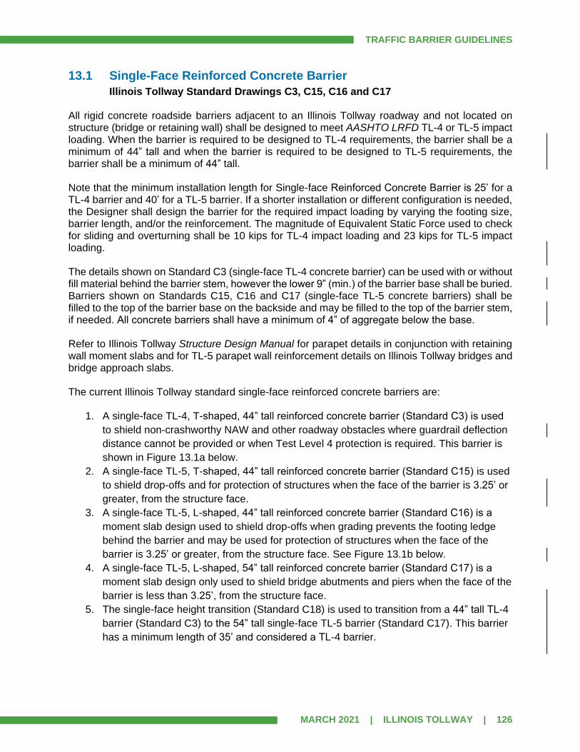
TRAFFIC BARRIER GUIDELINES
MARCH 2021 | ILLINOIS TOLLWAY | 126
13.1 Single-Face Reinforced Concrete Barrier
Illinois Tollway Standard Drawings C3, C15, C16 and C17 All rigid concrete roadside barriers adjacent to an Illinois Tollway roadway and not located on structure (bridge or retaining wall) shall be designed to meet AASHTO LRFD TL-4 or TL-5 impact loading. When the barrier is required to be designed to TL-4 requirements, the barrier shall be a minimum of 44” tall and when the barrier is required to be designed to TL-5 requirements, the barrier shall be a minimum of 44” tall. Note that the minimum installation length for Single-face Reinforced Concrete Barrier is 25’ for a TL-4 barrier and 40’ for a TL-5 barrier. If a shorter installation or different configuration is needed, the Designer shall design the barrier for the required impact loading by varying the footing size, barrier length, and/or the reinforcement. The magnitude of Equivalent Static Force used to check for sliding and overturning shall be 10 kips for TL-4 impact loading and 23 kips for TL-5 impact loading. The details shown on Standard C3 (single-face TL-4 concrete barrier) can be used with or without fill material behind the barrier stem, however the lower 9” (min.) of the barrier base shall be buried. Barriers shown on Standards C15, C16 and C17 (single-face TL-5 concrete barriers) shall be filled to the top of the barrier base on the backside and may be filled to the top of the barrier stem, if needed. All concrete barriers shall have a minimum of 4” of aggregate below the base. Refer to Illinois Tollway Structure Design Manual for parapet details in conjunction with retaining wall moment slabs and for TL-5 parapet wall reinforcement details on Illinois Tollway bridges and bridge approach slabs. The current Illinois Tollway standard single-face reinforced concrete barriers are:
1. A single-face TL-4, T-shaped, 44” tall reinforced concrete barrier (Standard C3) is used
to shield non-crashworthy NAW and other roadway obstacles where guardrail deflection
distance cannot be provided or when Test Level 4 protection is required. This barrier is
shown in Figure 13.1a below.
2. A single-face TL-5, T-shaped, 44” tall reinforced concrete barrier (Standard C15) is used
to shield drop-offs and for protection of structures when the face of the barrier is 3.25’ or
greater, from the structure face.
3. A single-face TL-5, L-shaped, 44” tall reinforced concrete barrier (Standard C16) is a
moment slab design used to shield drop-offs when grading prevents the footing ledge
behind the barrier and may be used for protection of structures when the face of the
barrier is 3.25’ or greater, from the structure face. See Figure 13.1b below.
4. A single-face TL-5, L-shaped, 54” tall reinforced concrete barrier (Standard C17) is a
moment slab design only used to shield bridge abutments and piers when the face of the
barrier is less than 3.25’, from the structure face.
5. The single-face height transition (Standard C18) is used to transition from a 44” tall TL-4
barrier (Standard C3) to the 54” tall single-face TL-5 barrier (Standard C17). This barrier
has a minimum length of 35’ and considered a TL-4 barrier.
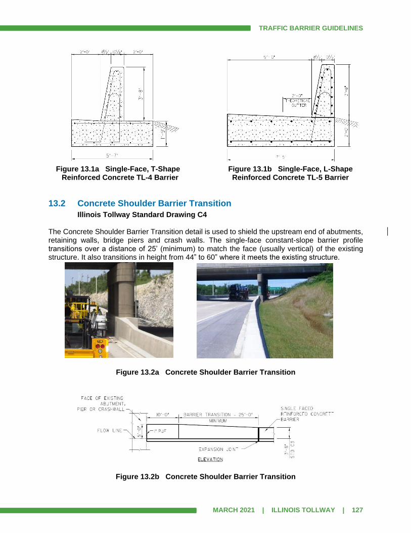
TRAFFIC BARRIER GUIDELINES
MARCH 2021 | ILLINOIS TOLLWAY | 127
Figure 13.1a Single-Face, T-Shape Figure 13.1b Single-Face, L-Shape Reinforced Concrete TL-4 Barrier Reinforced Concrete TL-5 Barrier
13.2 Concrete Shoulder Barrier Transition
Illinois Tollway Standard Drawing C4 The Concrete Shoulder Barrier Transition detail is used to shield the upstream end of abutments, retaining walls, bridge piers and crash walls. The single-face constant-slope barrier profile transitions over a distance of 25’ (minimum) to match the face (usually vertical) of the existing structure. It also transitions in height from 44” to 60” where it meets the existing structure.
Figure 13.2a Concrete Shoulder Barrier Transition
Figure 13.2b Concrete Shoulder Barrier Transition
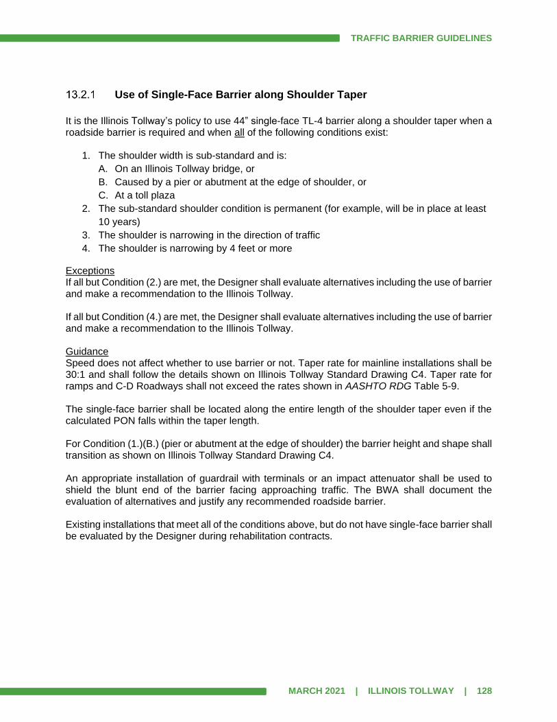
TRAFFIC BARRIER GUIDELINES
MARCH 2021 | ILLINOIS TOLLWAY | 128
Use of Single-Face Barrier along Shoulder Taper
It is the Illinois Tollway’s policy to use 44” single-face TL-4 barrier along a shoulder taper when a roadside barrier is required and when all of the following conditions exist:
1. The shoulder width is sub-standard and is:
A. On an Illinois Tollway bridge, or
B. Caused by a pier or abutment at the edge of shoulder, or
C. At a toll plaza
2. The sub-standard shoulder condition is permanent (for example, will be in place at least
10 years)
3. The shoulder is narrowing in the direction of traffic
4. The shoulder is narrowing by 4 feet or more
Exceptions If all but Condition (2.) are met, the Designer shall evaluate alternatives including the use of barrier and make a recommendation to the Illinois Tollway. If all but Condition (4.) are met, the Designer shall evaluate alternatives including the use of barrier and make a recommendation to the Illinois Tollway. Guidance Speed does not affect whether to use barrier or not. Taper rate for mainline installations shall be 30:1 and shall follow the details shown on Illinois Tollway Standard Drawing C4. Taper rate for ramps and C-D Roadways shall not exceed the rates shown in AASHTO RDG Table 5-9. The single-face barrier shall be located along the entire length of the shoulder taper even if the calculated PON falls within the taper length. For Condition (1.)(B.) (pier or abutment at the edge of shoulder) the barrier height and shape shall transition as shown on Illinois Tollway Standard Drawing C4. An appropriate installation of guardrail with terminals or an impact attenuator shall be used to shield the blunt end of the barrier facing approaching traffic. The BWA shall document the evaluation of alternatives and justify any recommended roadside barrier. Existing installations that meet all of the conditions above, but do not have single-face barrier shall be evaluated by the Designer during rehabilitation contracts.

TRAFFIC BARRIER GUIDELINES
MARCH 2021 | ILLINOIS TOLLWAY | 129
13.3 Concrete Barrier Double Face (44”)
Illinois Tollway Standard Drawing C5 Concrete Barrier Double Face is considered a TL-5 barrier when it is used to separate traffic lanes. It should also be used to separate a C-D roadway from the thru lanes. Concrete Barrier Double Face shall not be used to shield roadside obstacles or drop-offs. The current Illinois Tollway Standard uses a 44” tall constant-slope safety shape for this barrier. When using variable height median barrier and the vertical differential exceeds 12”, the Designer shall provide a plan detail showing the reinforcement needed to retain the vertical difference.
Figure 13.3 Concrete Barrier Double Face (44”)
Resurfacing may affect the height at which a vehicle impacts the roadway or bridge barrier.
1. For a 42” or 44” original height concrete barrier, the minimum height after resurfacing
shall be 39”. If the resulting height after an overlay will be less than 39”, then the barrier
shall be raised to provide a 44” height.
2. For a 32” original height concrete barrier, the minimum height after resurfacing shall be
44”. To accomplish this, the barrier height shall be raised 1’-0” plus the thickness of the
overlay. A 10’-0” minimum vertical transition (no steeper than 10H:1V) shall be installed
where needed to match abutting barrier height not being modified. Light pole and
overhead truss support openings within the raised wall sections shall be covered to
shield a potential snag point for an errant vehicle during impact.
When the project scope of work will not affect the height of the barrier no modifications are required.
13.4 Concrete Barrier Reflectors
Illinois Tollway Standard Drawing D4 Concrete barrier reflector Type C reflective face may be fabricated from material meeting the intensities and reflective values per the Standard Specifications. The direct applied concrete barrier reflector is rectangular in shape, mono-directional and has a minimum of 9.0 sq. in. of effective reflective area.

TRAFFIC BARRIER GUIDELINES
MARCH 2021 | ILLINOIS TOLLWAY | 130
Figure 13.4 Concrete Barrier Reflectors
Reference Illinois Tollway Standard Drawing D4 for spacing requirements.