TOYOTA TUNDRA MY 2007 - SUPERCHARGER FIT...
55
TOYOTA TUNDRA MY 2007 - SUPERCHARGER FIT KIT Preparation Page 1 of 55 pages Issue: E 7/22/09 #4 Coolant Cross Over Manifold TRD Air Filter & Air Box Lid #2 #3 TUNDRA FIT KIT: PTR29-34100 Item Qty Req’d Description 1 1 Low Temperature Radiator (LTR) 2 1 TRD Air Filter 3 1 Air Box Lid 4 1 Coolant Cross Over Manifold 5 1 Hardware Bag “A” 6 1 Hardware Bag “B” 7 1 Hardware Bag “C” 8 1 Hardware Bag “D” 9 1 8 Rib Belt 10 1 Hardware Bag “E” 11 1 Hardware Bag “F” 12 1 Hardware Bag “G” 13 1 Hardware Bag “H” Hardware Bag “B” Contents Hardware Bag “A” Contents Item Qty Req’d Description 1 1 Reservoir Mounting Bracket 2 1 Relay with Wire Harness Assembly 3 1 Intercooler Pump Mounting Bracket 4 8 Wide Band Spring Clamp 5 10 Lock Ties (Short) 6 1 90˚ Plastic Elbow 7 2 Adel #36 Clamp 8 2 Fuses: 15 amp ATC, 10 amp mini fuse 9 1 5/16” ID X 1-1/4” OD Flat Washer 10 1 M6 X 20 mm Hex Flange Head Bolt 11 1 M8 X 20 mm Hex Flange Head Bolt 12 5 M6 Hex Flange Nut 13 3 M6 X 12 mm Hex Flange Head Bolt 14 3 Swivel Spacer 15 1 Harness Clip 16 1 “C” Clip 17 6 Lock Ties (1/2” Wide) 18 2 #10 Hose Clamp A5 A1 A4 A3 A2 A6 A7 A8 A9 A10 A11 A12 A13 A17 A14 A15 A16 A18 #1 Item Qty Req’d Description 1 1 ¾” Coolant Hose, 4” X 60” 2 1 ¾” Coolant Hose, 4” X 36” 3 1 ¾” Coolant Hose, 4” X 36” 4 36” 1” Convoluted Tube 5 26” 11/32” DOT Brake Vacuum Hose 6 6” ½” Coolant Hose 7 9” 3/8” Convoluted Tube B1 B5 B2 B3 B4 B6 B7
Transcript of TOYOTA TUNDRA MY 2007 - SUPERCHARGER FIT...

TOYOTA TUNDRA MY 2007 - SUPERCHARGER FIT KIT Preparation
Page 1 of 55 pages Issue: E 7/22/09
#4
Coolant Cross Over Manifold
TRD Air Filter & Air Box Lid #2 #3
TUNDRA FIT KIT: PTR29-34100 Item Qty Req’d Description 1 1 Low Temperature Radiator (LTR) 2 1 TRD Air Filter 3 1 Air Box Lid 4 1 Coolant Cross Over Manifold 5 1 Hardware Bag “A” 6 1 Hardware Bag “B” 7 1 Hardware Bag “C” 8 1 Hardware Bag “D” 9 1 8 Rib Belt 10 1 Hardware Bag “E” 11 1 Hardware Bag “F” 12 1 Hardware Bag “G” 13 1 Hardware Bag “H”
Hardware Bag “B” Contents
Hardware Bag “A” Contents Item Qty Req’d Description 1 1 Reservoir Mounting Bracket 2 1 Relay with Wire Harness Assembly 3 1 Intercooler Pump Mounting Bracket 4 8 Wide Band Spring Clamp 5 10 Lock Ties (Short) 6 1 90˚ Plastic Elbow 7 2 Adel #36 Clamp 8 2 Fuses: 15 amp ATC, 10 amp mini fuse 9 1 5/16” ID X 1-1/4” OD Flat Washer 10 1 M6 X 20 mm Hex Flange Head Bolt 11 1 M8 X 20 mm Hex Flange Head Bolt 12 5 M6 Hex Flange Nut
13 3 M6 X 12 mm Hex Flange Head Bolt 14 3 Swivel Spacer
15 1 Harness Clip 16 1 “C” Clip
17 6 Lock Ties (1/2” Wide) 18 2 #10 Hose Clamp
A5A1A4
A3
A2
A6
A7
A8
A9
A10
A11A12
A13
A17
A14A15A16
A18
#1
Item Qty Req’d Description 1 1 ¾” Coolant Hose, 4” X 60” 2 1 ¾” Coolant Hose, 4” X 36” 3 1 ¾” Coolant Hose, 4” X 36” 4 36” 1” Convoluted Tube 5 26” 11/32” DOT Brake Vacuum Hose 6 6” ½” Coolant Hose 7 9” 3/8” Convoluted Tube
B1
B5
B2
B3
B4B6
B7

TOYOTA TUNDRA MY 2007 - SUPERCHARGER FIT KIT Preparation
Page 2 of 55 pages Issue: E 7/22/09
E1 E2
E3
Item # Qty Req’d Description 1 1 Air Inlet Rubber Bellows w/ Clamps 2 1 Inlet Air Flow Accelerator 3 1 Filter Minder with Grommet
Hardware Bag “E” Contents
Hardware Bag “G” Contents Item Qty Req’d Description 1 1 Idler Bracket 2 1 Idler Pulley 3 1 M10 X 30 mm Hex Flange Head Bolt 4 2 M10 X 85 mm Hex Flange Head Bolt 5 1 M8 X 80 mm Allen Socket Head Bolt
G1G2 G4 G5G3
Hardware Bag “F” Contents
F2 F1
F3
Item Qty Req’d Description 1 8 Fuel Injectors, - High Flow 2 8 Spark Plugs IKH22 3 1 Fuel Pump
#9
Hardware Bag “C” Contents Item Qty Req’d Description 1 1 Oil Cooler Tube Manifold 2 1 Thermostat Bypass Manifold 3 4 #7 Hose clamp 4 1 M6 X 30 mm Allen Stud 5 1 M6 Hex Flange Nut 6 1 PCV Hose 7 1 PCV Hose Clamp
Hardware Bag “D” Contents Item # Qty Req’d Description 1 1 Intercooler Pump 2 1 Intercooler Res. with Cap & Bolts
D1 D2
C1
C6
C2
C5 C4
C3
C7

TOYOTA TUNDRA MY 2007 - SUPERCHARGER FIT KIT Preparation
Page 3 of 55 pages Issue: E 7/22/09
Item Qty Req’d Description 1 2 Sticker, TRD Supercharged 2 2 Sticker, TRD Development 3 2 Sticker, Premium Fuel Warning 4 2 Sticker, TRD Red TRD Logo 5 1 Warranty certificate, TRD 6 1 Warranty Registration Card 7 1 Mirror Hanger, S/C Noise 8 1 Label, Vacuum and Belt Routing 9 1 Label, CARB D-425-32
Hardware Bag “H” Contents
Kit Contents (MAIN SUPERCHARGER KIT) P/N PTR29-34070 Item Qty Req’d Description 1 1 Main Supercharger Assembly 2 1 Hardware Bag “J” – SEE BELOW
#1
Hardware Bag “J” Contents Item Qty Req’d Description 1 1 Fuel Pump Module O-Ring 2 1 Throttle Body O-Ring 3 1 Fuel Pump Discharge O-Ring 4 1 Wire Harness Clip
J1 J2
J3
J4

TOYOTA TUNDRA MY 2007 - SUPERCHARGER FIT KIT Preparation
Page 4 of 55 pages Issue: E 7/22/09
Additional Items Required For Installation Item # Quantity Reqd. Description 1 1 Main Supercharger Assembly,
P/N PTR29-34070 2 2 Water Outlet Gasket, P/N
16341-38030
Conflicts TRD Performance Air Intake System for N/A Engines: PTR03-34070, PTR03-34090, PTR03-34100
Recommended Tools Personal & Vehicle Protection
Notes
Safety Glasses Fender Blankets Protective Gloves Special Tools Notes Toyota T.I.S. Techstream Version 4.12.001 or Later GR8 Battery Charger Fuel Pump Retainer SST P/N 09808-14020 Hoist Bracket P/N PTR25-34070 Installation Tools Notes Mechanic’s Hand Tools Combo wrenches & sockets ½” & 3/8” Torque Wrenches 12mm - 6pt 3/8 drive Swivel Socket
Craftsman #43203 or equivalent
Special Chemicals Notes Anti-Seize Assembly Lube For Spark Plugs
General Applicability All Tundras with 3UR-FE 5.7L V-8 Engine Gasoline Fuel Only (Not for use on-Flex Fuel Engines (FFV))
Recommended Sequence of Application Item # Accessory 1 Not Applicable
*Mandatory
Vehicle Service Parts (may be required for reassembly) Item # Quantity Reqd. Description 1 1 Gallon* Toyota Pre-Mix Antifreeze
Coolant 2 A/R Form In Place Gasket (FIPG),
P/N 00295-00103
* Additional coolant will be required if the original coolant is not saved and reused.
Legend NOTE: THIS SUPERCHARGER SYSTEM IS NOT COMPATIBLE WITH FLEX-FUEL VEHICLES (FFV). Recommended Installer Skill Level: Expert Technician or higher.
STOP: Damage to the vehicle may occur. Do not proceed until process has been complied with. OPERATOR SAFETY: Use caution to avoid risk of injury. CAUTION: A process that must be carefully observed in order to reduce the risk of damage to the accessory/vehicle and to ensure a quality installation.TOOLS & EQUIPMENT: Used in Figures calls out the specific tools and equipment recommended for this process. REVISION MARK: This mark highlights a change in installation with respect to previous issue. SAFETY TORQUE: This mark indicates that torque is related to safety.

TOYOTA TUNDRA MY – 2007 - SUPERCHARGER FIT KIT Procedure
Page 5 of 55 pages Issue: E 7/22/09
Care must be taken when installing this accessory to ensure damage does not occur to the vehicle. The installation of this accessory should follow approved guidelines to ensure a quality installation. These guidelines can be found in the "Accessory Installation Practices" document. This document covers such items as:-
• Vehicle Protection (use of covers and blankets, cleaning chemicals, etc.). • Safety (eye protection, rechecking torque procedure, etc.). • Vehicle Disassembly/Reassembly (panel removal, part storage, etc.). • Electrical Component Disassembly/Reassembly (battery disconnection, connector removal, etc.). • The TIS Repair Manual can be referenced for additional details.
Please see your Toyota dealer for a copy of this document.
1. Installation Review and Vehicle Preparation.
(a) Review the entire instruction instructions provided before beginning the installation
(b) Review the parts list/kit contents to ensure that all parts are present before beginning the installation. If any items are missing contact Technical Support at (800) 688-5912 before proceeding.
(c) Remove any low-octane fuel from the vehicle. Ensure that ONLY 91 octane or higher unleaded gasoline is used.
(d) Place the vehicle onto vehicle hoist.
(e) Protect the vehicle with protection blankets over the fenders and front of the vehicle.
(f) Disconnect and remove the battery.
(g) When draining the cooling system into a clean container in Step 3, save this coolant as it will be reused. CAUTION: To avoid the danger of being burned, do not remove the radiator cap while the engine and radiator are still hot. Thermal expansion will cause the hot engine coolant and steam to blow out from the radiator.
(h) All parts that are removed and not reused should be saved for the customer, i.e., “discard” means to save for the customer.

TOYOTA TUNDRA MY – 2007 - SUPERCHARGER FIT KIT Procedure
Page 6 of 55 pages Issue: E 7/22/09
Fig 2-2
Fig 3-1
Fig 2-1
2. Cover Removal. (a) Remove the engine V-bank cover by Lifting
the front of the cover and pulling away from the firewall (Fig 2-1). Discard these parts.
(b) If installed, remove the No. 1 engine under cover (Fig 2-2) by removing the 3 screws and 5 bolts. Save these parts for reuse.
3. Drain Engine Coolant.
CAUTION: Do not remove the radiator cap while the engine and radiator are still hot. Pressurized, hot engine coolant and steam may be released and cause serious burns. (a) Loosen the radiator drain cock plug
(Fig. 3-1).
(b) Remove the radiator cap. Then drain the coolant from the radiator into a clean container so it can be reused (Fig. 3-1).
(c) Loosen the 2 cylinder block drain cock plugs (Fig.3-1). Then drain the coolant from the engine and save for reuse.
(d) Tighten the 2 cylinder block drain cock plugs. Torque: 13 Nm (10 ft lbf)

TOYOTA TUNDRA MY – 2007 - SUPERCHARGER FIT KIT Procedure
Page 7 of 55 pages Issue: E 7/22/09
Fig 4-2
Fig 4-1
Fig 4-3
Fig 5-1
4. Fan and Shroud Removal. (a) Remove the upper radiator hose. Mark the
radiator end of this hose with a marker or tape. This hose will be re-installed inverted and the mark will help identify the ends.
(b) Loosen the 4 nuts holding the fluid coupling fan (Figs. 4-1).
(c) Remove the fan/generator V-rib belt. Discard this belt as it will be replaced by a new belt.
(d) Disconnect the reservoir hose from the upper radiator tank.
(e) For vehicles with Trailer Towing System: Detach the claw to open the No. 1 hose clamp on the side of the fan shroud (Fig 4-2).
(f) Remove the 2 bolts holding the fan shroud (Figs 4-3). Remove the 4 nuts of the fluid coupling fan, and then remove the shroud together with the coupling fan. Retain these parts for reuse. Temporarily re-install the 4 nuts to keep the pulley in place (reference Fig 4-1). Do not tighten.
CAUTION: Be careful not to damage the radiator core. It is helpful to protect the radiator core with a piece of cardboard to prevent damage during subsequent steps.
5. Air Cleaner Lower Box Replacement.
(a) Remove the air cleaner hose by disconnecting the vacuum and ventilation hoses and loosening the 2 clamps. (Fig 5-1). Discard this hose and clamps.

TOYOTA TUNDRA MY – 2007 - SUPERCHARGER FIT KIT Procedure
Page 8 of 55 pages Issue: E 7/22/09
Fig 5-3
Fig 5-5
Fig 5-2
(b) Remove the air cleaner lid by disconnecting the MAF meter connector, using a clip removal tool to detach the wire harness clamp, and unfastening the 4 hook clamps (Figs 5-2). Remove and discard the air cleaner element.
(c) Remove the MAF meter from the air cleaner
lid (Fig 5-3). Discard the air cleaner lid and retain the 2 screws.
(d) Install the MAF meter in the new air cleaner
lid using the OE screws (Fig 5-3). Torque: 1.7 Nm (15 in lbf)
(e) Install the Filter Minder by inserting the grommet into the air box top making sure the groove in the grommet is lined up with the air box cover surface. Lubricate the filter Minder barbed end and push into the grommet. (Fig 5-4)
(f) Remove the air cleaner case by removing the
2 bolts (Fig 5-5).
Fig 5-4
Insert Grommet 1st.

TOYOTA TUNDRA MY – 2007 - SUPERCHARGER FIT KIT Procedure
Page 9 of 55 pages Issue: E 7/22/09
Fig 5-7
Fig 6-2
Fig 6-1
Fig 5-6
(g) Using a flat blade screwdriver, unclip and discard the air inlet tube from the air cleaner case (Fig 5-6).
(h) Install the new air flow accelerator (E2) into
the opening in the inner fender panel (Fig 5-7). It will be necessary to squeeze and compress the bell mouth of the air flow accelerator in order to get it through the opening in the inner fender.
(i) Reinstall the air cleaner case using the
original bolts. The inlet to the case is inserted into and snaps to the air flow accelerator. Once the two parts are snapped together, push the air flow accelerator further through the panel so the bolt holes line up. Torque: 5.0 Nm (44 in lbf)
6. Intake Manifold Removal
(a) Blow away dirt and debris that has accumulated around the intake manifold ports and the fuel injectors. Wear eye protection when using compressed air.
(b) Disconnect the ventilation hose from the
ventilation pipe on the cylinder head covers, LH and RH (Fig 6-1).
(c) Disconnect the 2 water by-pass hoses and the
throttle body connector (Fig 6-2).

TOYOTA TUNDRA MY – 2007 - SUPERCHARGER FIT KIT Procedure
Page 10 of 55 pages Issue: E 7/22/09
Fig 6-4
Fig 6-5
Fig 6-6
(d) Remove 4 bolts and remove the throttle body from the manifold. Save these bolts and the throttle body. Discard the throttle body gasket (Fig 6-3).
(e) Disconnect the No. 1 ventilation hose
(Fig 6-4).
(f) Remove the No. 1 engine cover sub-
assembly (Fig 6-5). Discard this part.
(g) Remove the No. 3 engine cover (Fig 6-6). Discard this part.
Fig 6-3

TOYOTA TUNDRA MY – 2007 - SUPERCHARGER FIT KIT Procedure
Page 11 of 55 pages Issue: E 7/22/09
Fig 6-7
Fig 6-9
(h) Disconnect the purge VSV connector, the hose from the VSV, and the ACIS connector (Fig 6-7). Disconnect the purge line hose from the body of the purge valve. Disconnect the purge hose from the front of the intake manifold, but leave it connected to the front of the purge valve. Unbolt the purge valve and set it and the bolt aside for now.
(i) Remove the brake booster vacuum hose from the manifold pipe and the brake booster (Fig 6-8). Save the clamps, but discard the hose.
(j) Disconnect the 3 wire clamps from the 3 wire
harness brackets (Fig 6-9). (k) Using the 12mm – 6 pt 3/8” drive swivel
socket remove the 2 nuts, 8 bolts and the intake manifold (Fig 6-10). See recommended tools list page 4.
Fig 6-8
Fig 6-10
12 mm swivel

TOYOTA TUNDRA MY – 2007 - SUPERCHARGER FIT KIT Procedure
Page 12 of 55 pages Issue: E 7/22/09
Fig 6-13
(l) Remove the 2 harness clips from the back of the intake manifold. These will be reused in step 12 (b). (Fig. 6-11)
(m) Clean and cover the intake ports to prevent debris from entering the engine and then remove and discard the 2 foam engine covers that are under the intake manifold (Fig 6-12). Blow away any debris that may be in the engine valley.
(n) Remove the 2 bolts and ventilation hose from
the intake manifold (Fig 6-13). Set the hose aside for later reuse.
(o) Carefully remove the gaskets from the bottom of the intake manifold, clean and set aside they will be reused in step 12. Discard the intake manifold and remaining attached parts (Fig 6-14).
CAUTION: Be careful not to damage the gaskets. . If the gaskets appear to be worn or damaged, then replace the gaskets with new ones (Qty 2: Toyota P/N 17171-38010 or 17171-0S010 or equivalent superseded part).
Fig 6-14
Fig 6-11
Fig 6-12
Cover Intake Ports
Foam Engine Covers

TOYOTA TUNDRA MY – 2007 - SUPERCHARGER FIT KIT Procedure
Page 13 of 55 pages Issue: E 7/22/09
Fig 7-1
Fig 7-2
Fig 7-4
7. Water By-pass Joint Removal.
(a) Unplug the water temperature sensor, remove the sensor, and set it aside (Fig 7-1). Do not misplace the copper sealing washer.
(b) Remove the water by-pass hose No. 1 (lower heater hose) and discard it (Fig 7-2)
(c) Remove the water by-pass hose No. 2 from
the heater tube (upper heater hose) (Fig 7-3).
NOTE: If the vehicle is equipped with a towing package, proceed to step 7. (d), otherwise, jump to step 7. (h)
(d) Remove the 2 nuts and 2 stud bolts that attach the A/C compressor and slide the compressor out away from the engine on the 2 studs (Fig 7-4). It is not necessary to completely remove the compressor.
Fig 7-3
TOYOTA TUNDRA MY – 2007 - SUPERCHARGER FIT KIT Procedure
Page 14 of 55 pages Issue: E 7/22/09
Fig 7-6
Fig 7-5
Fig 8-1
4X
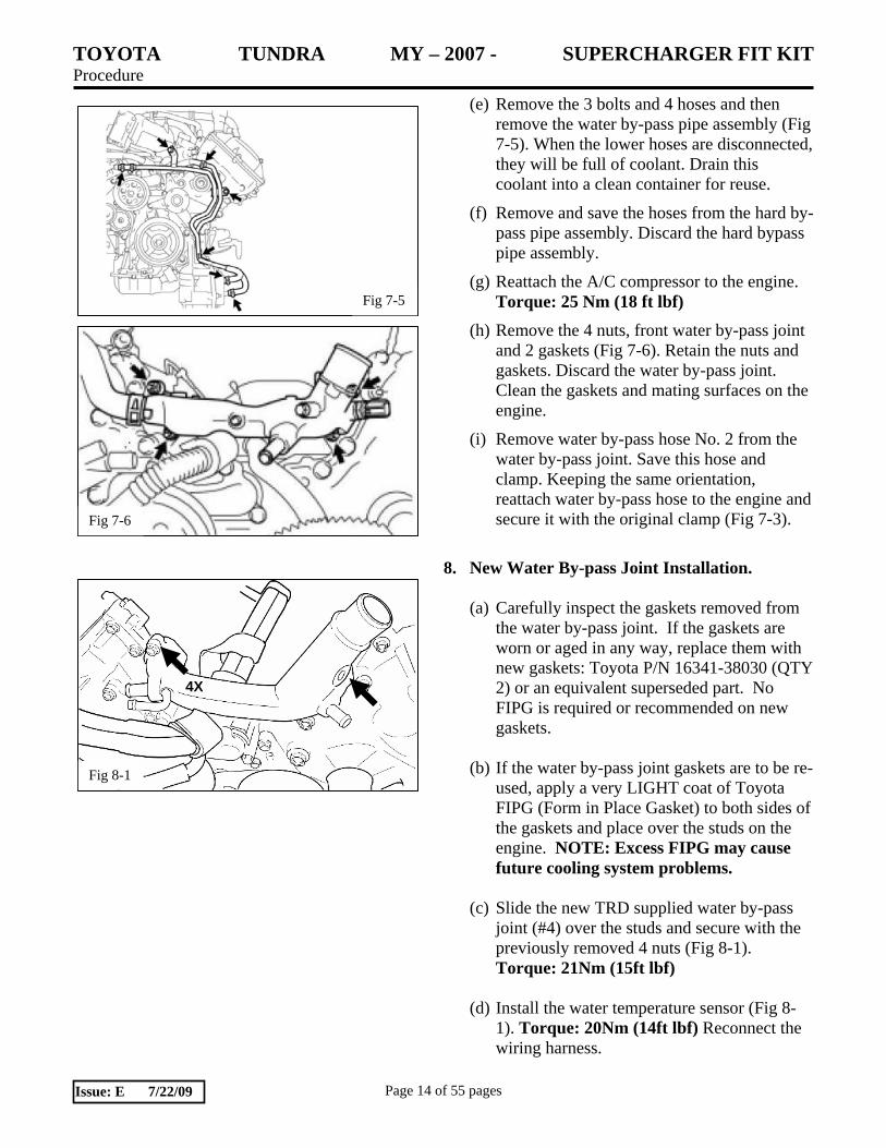
(e) Remove the 3 bolts and 4 hoses and then remove the water by-pass pipe assembly (Fig 7-5). When the lower hoses are disconnected, they will be full of coolant. Drain this coolant into a clean container for reuse.
(f) Remove and save the hoses from the hard by-pass pipe assembly. Discard the hard bypass pipe assembly.
(g) Reattach the A/C compressor to the engine. Torque: 25 Nm (18 ft lbf)
(h) Remove the 4 nuts, front water by-pass joint and 2 gaskets (Fig 7-6). Retain the nuts and gaskets. Discard the water by-pass joint. Clean the gaskets and mating surfaces on the engine.
(i) Remove water by-pass hose No. 2 from the water by-pass joint. Save this hose and clamp. Keeping the same orientation, reattach water by-pass hose to the engine and secure it with the original clamp (Fig 7-3).
8. New Water By-pass Joint Installation.
(a) Carefully inspect the gaskets removed from
the water by-pass joint. If the gaskets are worn or aged in any way, replace them with new gaskets: Toyota P/N 16341-38030 (QTY 2) or an equivalent superseded part. No FIPG is required or recommended on new gaskets.
(b) If the water by-pass joint gaskets are to be re-
used, apply a very LIGHT coat of Toyota FIPG (Form in Place Gasket) to both sides of the gaskets and place over the studs on the engine. NOTE: Excess FIPG may cause future cooling system problems.
(c) Slide the new TRD supplied water by-pass
joint (#4) over the studs and secure with the previously removed 4 nuts (Fig 8-1). Torque: 21Nm (15ft lbf)
(d) Install the water temperature sensor (Fig 8-
1). Torque: 20Nm (14ft lbf) Reconnect the wiring harness.

TOYOTA TUNDRA MY – 2007 - SUPERCHARGER FIT KIT Procedure
Page 15 of 55 pages Issue: E 7/22/09
Fig 9-1
Fig 9-2
Fig 9-3
Fig 9-4
9. Idler Pulley Installation.
(a) Remove the 2 M10 bolts and the 1 M8 bolt
from the engine timing chain cover and fan bracket (Fig 9-1). Discard these 3 bolts.
(b) Bolt the idler pulley bracket (G1) to the front
engine timing chain cover using the supplied 2 M10 bolts (G4) and 1 M8 allen socket head bolt (G5) (Fig 9-2). Torque: M10 Bolts, 47Nm (35 ft lbf) M8 Bolt 23 Nm (17 ft lbf)
NOTE: If the vehicle is equipped with a towing package, proceed to step 9 (c), otherwise, jump to step 9 (d)
(c) Route the No.6 water by-pass hose between
the two legs of the idler pulley bracket (Fig. 9-3).
(d) Bolt the idler pulley (G2) to the idler pulley
bracket with the M10 X 30 bolt (G3) (Fig 9-4). Torque: M10 Bolts, 47Nm (35ft lbf)

TOYOTA TUNDRA MY – 2007 - SUPERCHARGER FIT KIT Procedure
Page 16 of 55 pages Issue: E 7/22/09
Fig 10-1
Fig 10-2
Fig 10-3
Fig 10-4
10. Water Hose Installation.
(a) Re-connect the No. 2 water by-pass hose to
the water by-pass joint using the original clamp (Fig 10-1).
NOTE: If the vehicle is equipped with a towing package, proceed to step 10 (b), otherwise, jump to step 10 (g)
(b) Unclip the wire harness from the stud on the front of the timing cover on the driver side of the engine (Fig 10-2). Using an E-6 “Torx” socket, remove this stud and discard it.
(c) Using a 3 mm allen socket, install the M6 X
30 mm allen stud (C4) (Fig 10-2). Torque: 6 Nm (53 in lbf)
(d) Mount the oil cooler hard coolant lines (C1) to the M6 X 30 mm allen stud using the supplied M6 nut (C5) and the hoses at the top removed in step 7(f) using the OE clamps (Figs 7-5 & 10-3). Leave the nut finger tight.
NOTE: For clarity, some parts normally on
the engine are not shown. (e) Attach the coolant OE hoses from the oil
cooler to the lower ends of the hard coolant lines (Figs 7-5 & 10-4). Secure both ends of these hoses with the OE clamps.

TOYOTA TUNDRA MY – 2007 - SUPERCHARGER FIT KIT Procedure
Page 17 of 55 pages Issue: E 7/22/09
Fig 10-5
Fig 10-6
3” 2 ¾”
Fig 10-7
Fig 11-1
(f) Tighten the M6 nut and reattach the wire
harness clip (Fig 10-5). Torque: 10 Nm (7 ft lbf)
(g) Take the supplied ½” coolant hose (B6) and
cut one 2¾” length and one 3” length. Discard the extra left over hose. Slide the 2 ¾” length onto the short leg of the “J” shaped thermostat by-pass manifold (C2) and the 3” length of hose onto the longer leg (Fig 10-6). Secure with the supplied clamps (C3).
(h) Slide a supplied screw clamp (C3) on each
end of the “J” shaped by-pass manifold (C2) and attach it to the thermostat housing and the water by-pass joint (Fig 10-7). Ensure the tube fits comfortably without any kinks and tighten the screw clamps.
11. Fuel Injector Removal.
CAUTION: The fuel system is under high
pressure. Use safety glasses and fuel-compatible gloves to prevent personal injury.
(a) Unplug the No. 6 and No. 7 wire harness
connectors from the RH and LH fuel rail harnesses (Fig 11-1).

TOYOTA TUNDRA MY – 2007 - SUPERCHARGER FIT KIT Procedure
Page 18 of 55 pages Issue: E 7/22/09
Fig 11-2
Fig 11-3
Fig 11-4
(b) Disconnect the No. 2 fuel tube from the fuel pressure regulator (Fig 11-2). Place shop rags around the fitting to prevent fuel spray and to absorb any fuel that comes out of the line. Next, disconnect the No.1 fuel tube from the back of each fuel delivery pipe sub-assembly. Finally, disconnect the fuel tube sub assembly from the front of the LH fuel delivery pipe sub-assembly. Use shop rags to absorb any fuel as each connector is disconnected.
(c) Unbolt and remove the fuel delivery pipe
sub-assemblies. Retain the four bolts. (Fig 11-3).
CAUTION: The fuel delivery pipe sub-assemblies have fuel in them which must be drained into an approved disposal container.
NOTICE: When removing the delivery pipes, hold the pipes by the ends and pull it straight upwards. (d) Remove and retain the four spacers. Remove
the eight insulators from either the intake manifold or from the injectors. Clean and inspect for damage and wear. If any damage or wear is evident, replace all 8 insulators with new parts (Toyota P/N 23291-23010 or equivalent superseded part). Install the insulators into the cylinder heads.
(e) Remove the fuel injectors from the fuel
delivery pipes. As each injector is removed, disconnect the injector connector (Fig 11-4). Discard the injectors.
(f) Cover all eight injector ports in the cylinder
heads and all open fuel lines to prevent debris contamination.
12. Preparation for Supercharger Installation.
(a) Coat the intake manifold gaskets removed in step 6 (o) with a light film of oil and install them on the bottom of the supercharger. (Fig. 12-1) Fig 12-1
Lubricate gasket with oil

TOYOTA TUNDRA MY – 2007 - SUPERCHARGER FIT KIT Procedure
Page 19 of 55 pages Issue: E 7/22/09
Fig 12-3
(b) Install the wire harness clips removed in step 6 (l) onto the cast bosses on the back of the supercharger as shown. (Fig. 12-2)
Torque: 10 Nm (7 ft lbf)
(c) Attach the TRD hoist bracket to the top of the supercharger with the M8 bolts that are part of the hoist bracket kit (Fig 12-3). Torque: 21 Nm (15 ft lbf) Note: This bracket is not part of the kit and needs to be ordered separately, P/N PTR25-34070.
13. #1 Vent Hose Modification
(a) Identify which generation of supercharger you have by inspecting the vacuum hose barb area (Fig 13-1). The earlier generation has a boss height of about ¾” (Rev “A”), where the new generation has a boss height of about 1-1/4” (Rev “B”).
(b) Identify which generation of OE intake manifold the vehicle was equipped with (Fig 13-2) by inspecting the #1 vent hose. Earlier models have an outer hose diameter of about 16mm at the intake manifold side. Later models have an outer hose diameter of about 19mm.
(c) If the vehicle is equipped with the later 19mm OD hose, then discard the OE hose and utilize the hose (C6) and clamp (C7) supplied in the kit. If the vehicle is equipped with the earlier, 16mm OD hose then utilize the hose and clamp that came with the vehicle.
(d) If the supercharger is determined to be Rev “B”, then install the #1 vent hose to the end of the PCV valve and proceed to Step 15 – Supercharger Housing installation. Otherwise, proceed to the next step.
Fig 12-2
REV “A”
1-1/4”
Fig 13-1
REV “B”
3/4”
Fig 13-2 Earlier Models Later Models

TOYOTA TUNDRA MY – 2007 - SUPERCHARGER FIT KIT Procedure
Page 20 of 55 pages Issue: E 7/22/09
Fig 14-1
Fig 14-2
(e) If the supercharger is determined to be Rev “A”, then modification of the #1 vent hose is necessary. Modify the No. 1 ventilation hose by removing the bottom half of the insulation as shown. Then cut 2” from the bottom (Fig 13-3). Use a sharp razor blade to cut the insulation being careful not to cut the hose inside. Move the clamp from the removed section to the new bottom. Install the No. 1 ventilation hose onto the PCV valve (Fig 14-2).
14. Supercharger Housing Installation.
(a) Using an engine hoist, lift the supercharger by hooking the hoist to the hoist bracket bolted to the top of the supercharger.
(b) Remove the tape covering the intake ports in the cylinder heads. Make sure the surface is clean.
(c) Carefully, position the supercharger main housing on the intake ports (Fig.14-1). Do not pinch the No.1 ventilation hose (Fig. 14-2).
(d) Uniformly bolt the supercharger housing in place using the OE intake manifold fasteners removed in step 6 (k) (2 nuts + 8 bolts (Fig 14-3). Follow the tightening sequence in the figure. Torque: 21 Nm (15 ft lbf)
(e) Remove the hoist bracket. Save the hoist bracket and the 2 M8 bolts for future installations.
(f) Re-clip the factory wire harness into the harness clips behind the supercharger (Fig 12-2).
Fig 14-3
1
2
5
4
3
6
7
8
9
10
Fig 13-3
TOYOTA TUNDRA MY – 2007 - SUPERCHARGER FIT KIT Procedure
Page 21 of 55 pages Issue: E 7/22/09
Fig 14-4
Forward
Fig 14-5
Fig 14-6 Purge Line
Hose
To Forward Barb
Fig 14-7 Seal ACIS Connector with Tape
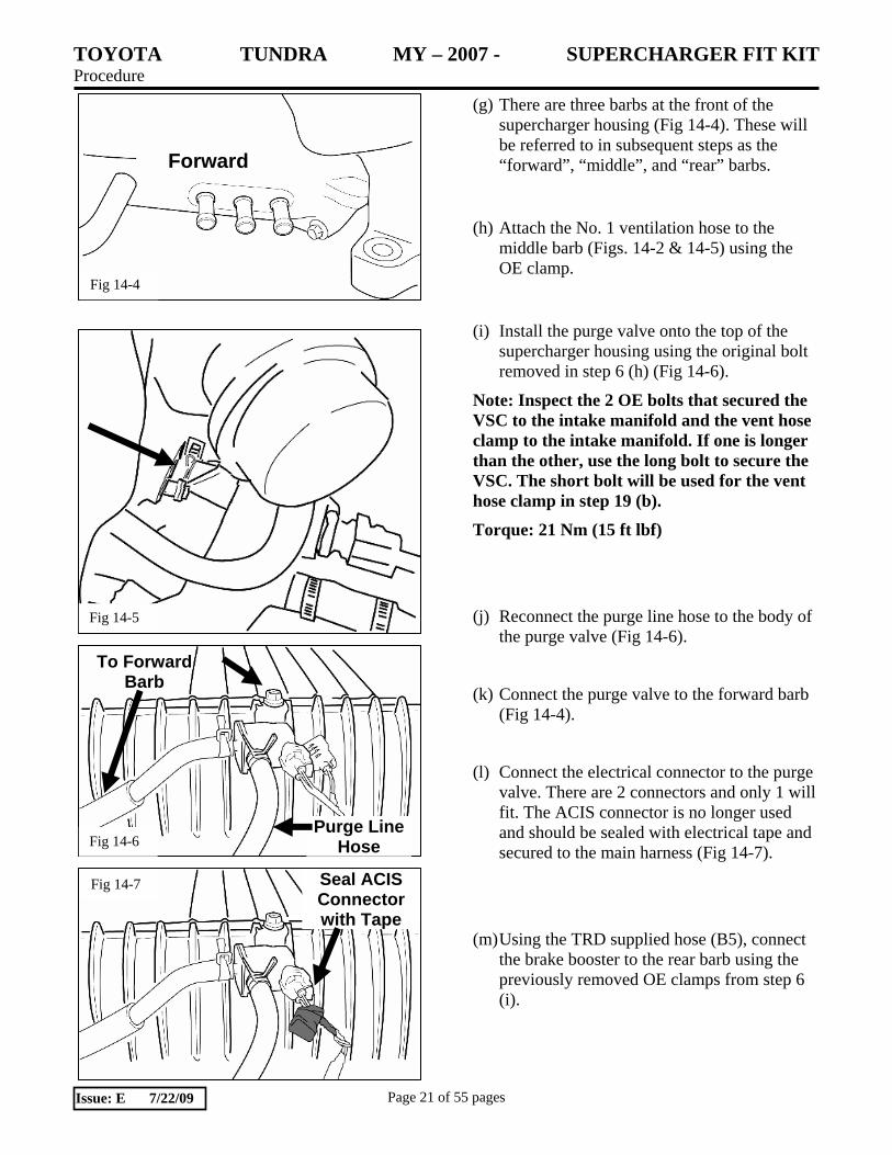
(g) There are three barbs at the front of the supercharger housing (Fig 14-4). These will be referred to in subsequent steps as the “forward”, “middle”, and “rear” barbs.
(h) Attach the No. 1 ventilation hose to the middle barb (Figs. 14-2 & 14-5) using the OE clamp.
(i) Install the purge valve onto the top of the supercharger housing using the original bolt removed in step 6 (h) (Fig 14-6).
Note: Inspect the 2 OE bolts that secured the VSC to the intake manifold and the vent hose clamp to the intake manifold. If one is longer than the other, use the long bolt to secure the VSC. The short bolt will be used for the vent hose clamp in step 19 (b).
Torque: 21 Nm (15 ft lbf)
(j) Reconnect the purge line hose to the body of the purge valve (Fig 14-6).
(k) Connect the purge valve to the forward barb (Fig 14-4).
(l) Connect the electrical connector to the purge valve. There are 2 connectors and only 1 will fit. The ACIS connector is no longer used and should be sealed with electrical tape and secured to the main harness (Fig 14-7).
(m) Using the TRD supplied hose (B5), connect the brake booster to the rear barb using the previously removed OE clamps from step 6 (i).

TOYOTA TUNDRA MY – 2007 - SUPERCHARGER FIT KIT Procedure
Page 22 of 55 pages Issue: E 7/22/09
Fig 15-4
Fig 15-1
New Original
Fig 15-3
15. Fuel Injector Installation.
(a) The new TRD supplied fuel injectors (F1) have a shorter nose than the original injectors (Fig 15-1).
(b) Connect the injector connector (Fig 15-2).
(c) Apply a light coat of gasoline or spindle oil onto the upper injector o-ring and install the injector to the fuel delivery pipe as shown (Fig 15-2).
NOTICE:
• Make sure that there are no scratches or foreign matter in or around the insertion hole of the delivery pipe.
• When inserting the injector, be careful not to damage the O-ring.
• Attach the part of the injector labeled B between the parts of the delivery pipe labeled A.
(d) Check to see that each injector is installed to the delivery pipe facing the directions shown in Fig 15-2. Apply a light coat of oil to the ID of the insulators in the cylinder heads.
(e) Install the 2 delivery pipe spacers and make sure the 4 insulators are in place in each cylinder head.
(f) Install the 2 delivery pipes (with injectors) to the cylinder heads.
(g) Install the 2 bolts on each side (Fig 15-4). Torque: 21 Nm (15 ft lbf)
Fig 15-2
O-Ring
Connector

TOYOTA TUNDRA MY – 2007 - SUPERCHARGER FIT KIT Procedure
Page 23 of 55 pages Issue: E 7/22/09
Fig 16-1
Fig 15-5
Fig 16-2
Connector Toward rear of the vehicle
Fig 16-3
(h) Reconnect the No. 6 and No. 7 wire harness connectors. (Fig 15-5).
(i) Reconnect the 4 fuel line connectors, 2 per side, previously disconnected (Fig 15-5).
16. Throttle Body Installation.
(a) Install the supplied Throttle body O-ring (J2) in the groove on the nose of the supercharger housing (Fig 16-1).
(b) Install the throttle body onto the supercharger housing with the orientation rotated 180° from OE position so that the connector is toward the rear of the vehicle using the original 4 bolts (Fig 16-2). Torque: 21 Nm (15 ft lbf)
(c) Unclip the 3 wire harness clips (Fig 16-3). Remove the clips from the wire harness using a small flat blade screwdriver to release the lock tabs.

TOYOTA TUNDRA MY – 2007 - SUPERCHARGER FIT KIT Procedure
Page 24 of 55 pages Issue: E 7/22/09
Fig 16-5
Fig 16-6
(d) Unplug the 2 VVT sensors and the front air injection connector (Fig 16-4).
(e) Open the wire harness and remove the wire loom wrap up to the junction where the wire loom that contains the throttle and air injection wires branch out from the main harness to expose the throttle motor wires and air injection wires. Separate the throttle motor wires from the air injection wires (Fig 16-5).
(f) Install a 9” length of the supplied 3/8” convoluted tube (B7) over the exposed throttle motor wires and secure with electrical tape. Re-install the original wire loom wrap over the air injection wires and secure with electrical tape (Fig 16-6).
(g) Re-tape the rest of the harness closed. Attach the 3 clamps back onto the harness and clip them to their mounting brackets.
(h) Plug in the throttle body connector, the air injection connector, and the 2 VVT sensors. (Fig 16-7).
Fig 16-4
Fig 16-7

TOYOTA TUNDRA MY – 2007 - SUPERCHARGER FIT KIT Procedure
Page 25 of 55 pages Issue: E 7/22/09
Fig 16-9
Fig 17-2
(i) There are 2 water by-pass hoses as shown (Fig 16-8).
(j) Install the short throttle body water bypass hose so the natural 90 degree bend would be installed on the front facing barb on the throttle body. Install the other end of this hose to the water bypass joint. Secure using the OE spring clamps (Fig 16-9).
(k) Install the long throttle body water bypass hose so the natural 90 degree bend attaches to the thermostat housing. The other end attaches to the throttle body water connection facing the RH side of the vehicle. Secure with the OE spring clamps (Fig 16-9).
17. Belt, Fan & Fan Shroud, and Radiator Hose Installation (a) Install the supplied drive belt (#9) following
the outlined belt routing. Ensure the belt is completely on all of the pulleys (Fig 17-1).
(b) Remove anything covering the radiator used for core damage prevention.
(c) Remove the 4 nuts temporarily holding the fan pulley in place. Lower the fan and shroud together. Clip the fan shroud into the lower radiator mounting tabs (Fig 17-2).
(d) Bolt the fan clutch to the fan pulley using the 4 OE nuts (Fig 17-3). Torque: 21 Nm (15 ft lbf)
(e) Install the fan shroud using the 2 OE bolts (Fig 17-2). Torque: 6.5 Nm (58 in lbf)
Long Short
90° Ends
Fig 16-8
Fig 17-1
IP IP
AC
Fan WP
PS
ALT

TOYOTA TUNDRA MY – 2007 - SUPERCHARGER FIT KIT Procedure
Page 26 of 55 pages Issue: E 7/22/09
Fig 17-3
Fig 18-1
(f) Install the upper radiator hose. The radiator side of this hose should have been marked during removal, see step 4 (a). This marked side will now attach to the water bypass junction, and the other unmarked side to the radiator. Secure using the OE spring clamps.
(g) Connect the coolant overflow hose to the upper radiator tank.
18. Spark Plug Replacement. (a) Unplug and remove all 8 coils (Fig 18-1).
(b) Blow out any debris from the spark plug holes. (Wear eye protection)
(c) Remove and discard all 8 spark plugs.
(d) Apply a small amount of anti-seize to the threads of the new TRD supplied spark plugs (F2).
(e) Install all 8 spark plugs. (Plug Gap: 0.032”) Torque: 18 Nm (13 ft lbf) (f) Re-install all 8 coils.
Torque: 9 Nm (80 in lbf) (g) Reconnect the 8 coil connectors.
19. Vent Hose Installation. (a) The ventilation hose assembly is shown as
removed from the intake manifold (Fig 19-1). Remove the long hose from the “T”, flip it end for end, and reconnect it to the “T” (Fig 19-2). It will also be necessary to remove the clamp from the long hose, rotate it, and then reinstall it so it points toward the front of the engine (Fig 19-2).
Fig 19-2 Long Hose Flipped End
for End
Fig 19-1
“T” Long Hose Original Configuration
Middle Hose

TOYOTA TUNDRA MY – 2007 - SUPERCHARGER FIT KIT Procedure
Page 27 of 55 pages Issue: E 7/22/09
Fig 19-5
Fig 19-4
1” 2”
Fig 19-3
(b) Mount the ventilation hose assembly to the supercharger with the OE bolts. The M6 bolt attaches the “T” to the RH side of the supercharger housing (Fig 19-3). Torque: 10 Nm (7 ft lbf) The M8 bolt attaches the clamp on the long hose to the front of the supercharger housing (Fig 19-3).
Note: Be sure to use the short bolt here if the long bolt was used in step 14 (i).
Torque: 21 Nm (15 ft lbf)
(c) Connect the loose end of the long hose to the
LH cam cover (Fig 19-3).
(d) Remove the middle hose from the “T” and trim it so it will neatly fit between the “T” and the RH cam cover. Trim 1” off the end that attaches to the “T” and trim the other end so there is 2” from the trimmed end to the bottom of the longer leg (Fig 19-4).
(e) Trim the insulation so there is enough room for the clamps (Fig 19-5).
(f) Attach the modified middle hose to the “T” fitting and the RH cam cover (Fig 19-6).
(g) Leave the remaining hose connected to the “T” fitting loose for now (Fig 19-6).
Fig 19-6

TOYOTA TUNDRA MY – 2007 - SUPERCHARGER FIT KIT Procedure
Page 28 of 55 pages Issue: E 7/22/09
Fig 21-1
Fig 21-2
Fig 20-1
Fig 20-2
20. Air Inlet Installation. (a) Place screw clamps on each end of the air
box lid to throttle body rubber bellows (E1).
(b) Place the TRD supplied air filter in the air box base.
(c) Clip the supplied air box lid onto the air box base, and attach the inlet hose to the upper air box. Position the inlet hose so that it is in a natural position. Tighten the hose clamps (Fig 20-1). Torque: 4 Nm (35 in lbf)
(d) Connect the vent hose and fuel pressure regulator hose to the air inlet bellows (Fig 20-2).
(e) Plug in the MAF sensor and clip the harness to the air box lid.
21. Preparation for Intercooler Installation. (a) Disconnect the low pitch horn connector.
Unbolt and remove the low pitch horn (Fig 21-1). Set the horn and bolt aside for now.
(b) Disconnect the high pitch horn connector. Unbolt and remove the high pitch horn (Fig 21-2). Set the horn and bolt aside for now

TOYOTA TUNDRA MY – 2007 - SUPERCHARGER FIT KIT Procedure
Page 29 of 55 pages Issue: E 7/22/09
Fig 21-3
Fig 21-6
Fig 21-4
(c) Remove the LH and RH front end panels by removing the 2 clips on each with a clip remover and detaching the 2 pins (Fig 21-3).
NOTE: For vehicles with resin front bumpers, proceed to step 21 (d).
For vehicles with steel front bumpers skip to step 21 (g).
(d) Using a screwdriver, remove the two pin hold clips from each side (Fig 21-4). Then, using a clip remover, remove the 2 clips from each side.
(e) Using the same procedure for both sides, put protective tape on each side as shown (Fig 21-5). Using a clip remover, remove the 8 clips. Remove the 9 screws.
(f) Detach the 4 claws and remove the bumper cover. If the vehicle has fog lights and or intuitive assist parking, disconnect the connectors. (Fig 21-6).
Skip to step 21 (j).
Fig 21-5
Protective Tape

TOYOTA TUNDRA MY – 2007 - SUPERCHARGER FIT KIT Procedure
Page 30 of 55 pages Issue: E 7/22/09
Fig 21-7
Fig 21-8
Fig 21-9
Fig 21-10
(g) Place protective tape on each side as shown (Fig 21-7). Using a clip remover, remove the 8 clips and then remove the 16 bolts.
(h) Remove the screw and clip on both sides (Fig 21-8).
(i) Detach the 4 claws and 2 pins and remove the upper bumper cover (Fig 21-9).
(j) Remove the 6 nuts and the front upper center bumper retainer (Fig 21-10).
TOYOTA TUNDRA MY – 2007 - SUPERCHARGER FIT KIT Procedure
Page 31 of 55 pages Issue: E 7/22/09
Fig 21-12
Fig 21-11
Fig 21-14
Loosen this bolt
Fig 21-13
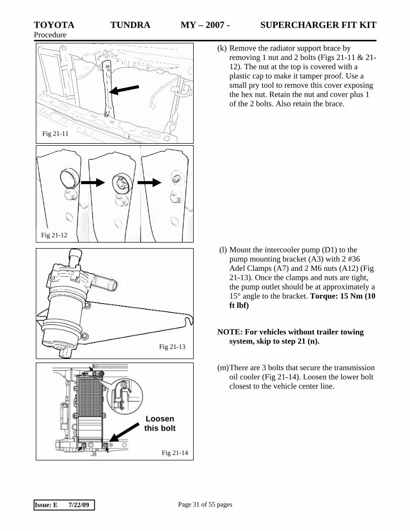
(k) Remove the radiator support brace by removing 1 nut and 2 bolts (Figs 21-11 & 21-12). The nut at the top is covered with a plastic cap to make it tamper proof. Use a small pry tool to remove this cover exposing the hex nut. Retain the nut and cover plus 1 of the 2 bolts. Also retain the brace.
(l) Mount the intercooler pump (D1) to the pump mounting bracket (A3) with 2 #36 Adel Clamps (A7) and 2 M6 nuts (A12) (Fig 21-13). Once the clamps and nuts are tight, the pump outlet should be at approximately a 15° angle to the bracket. Torque: 15 Nm (10 ft lbf)
NOTE: For vehicles without trailer towing system, skip to step 21 (n).
(m) There are 3 bolts that secure the transmission oil cooler (Fig 21-14). Loosen the lower bolt closest to the vehicle center line.
TOYOTA TUNDRA MY – 2007 - SUPERCHARGER FIT KIT Procedure
Page 32 of 55 pages Issue: E 7/22/09
Fig 21-15
Fig 21-16
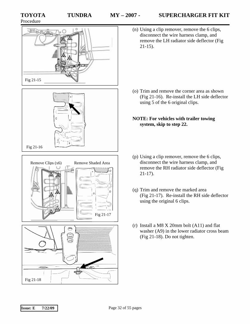
(n) Using a clip remover, remove the 6 clips, disconnect the wire harness clamp, and remove the LH radiator side deflector (Fig 21-15).
(o) Trim and remove the corner area as shown (Fig 21-16). Re-install the LH side deflector using 5 of the 6 original clips.
NOTE: For vehicles with trailer towing system, skip to step 22.
(p) Using a clip remover, remove the 6 clips, disconnect the wire harness clamp, and remove the RH radiator side deflector (Fig 21-17).
(q) Trim and remove the marked area (Fig 21-17). Re-install the RH side deflector using the original 6 clips.
(r) Install a M8 X 20mm bolt (A11) and flat washer (A9) in the lower radiator cross beam (Fig 21-18). Do not tighten.
Fig 21-18
Remove Clips (x6) Remove Shaded Area
Fig 21-17

TOYOTA TUNDRA MY – 2007 - SUPERCHARGER FIT KIT Procedure
Page 33 of 55 pages Issue: E 7/22/09
Fig 22-1
Fig 22-4
22. Intercooler Installation. (a) Set the intercooler low temperature radiator
(LTR) in front of the A/C condenser. Align the upper mounting tabs with the horn mounting holes and temporarily install the horn mounting bolts a few turns (Fig 22-1). Leave these bolts loose for now. Notice that the inlet and outlet on the LTR are on the driver side of the vehicle.
(b) Place the radiator support brace (removed in step 21 (k) back in place. The lower end of the brace is placed behind the lower mounting tab on the LTR. Insert the supplied M6 X 20 mm bolt (A10) a few turns, but do not tighten it. Place the OE M6 nut and M6 bolt in the upper mounting holes of the brace. Do not tighten.
(c) Lower the pump/mounting bracket assembly and install it by sliding the slots over the M8 & M6 bolts. Start with the passenger side slot and then lower the driver side slot. The mount goes back against the lower radiator cross beam behind the brace. When in place, it will look as shown (Fig 22-2). Tighten all the fasteners for the radiator support brace and the LTR pump mounting bracket. Torque: M6 = 8 Nm (71 in lbf), M8 = 20 Nm (15 ft lbf). Reinstall the plastic cap over the top nut of the radiator support brace.
(d) Remove 1 of the M8 horn mounting bolts and place the horn mounting tab on top of the LTR mounting tab. Secure with the OE bolt. Repeat for the other side. Torque: 20 Nm (15 ft lbf)
(e) For tow package vehicles only, unbolt the transmission oil cooler top bolt and let it hang out from the radiator upper cross member (Fig 22-3 & 22-4). Leave the fluid lines attached.
Fig 22-3
Fig 22-2
15º

TOYOTA TUNDRA MY – 2007 - SUPERCHARGER FIT KIT Procedure
Page 34 of 55 pages Issue: E 7/22/09
Fig 22-6
Fig 22-8
(f) The intercooler reservoir mounting bracket (A1) mounts to the upper RH corner of the vehicle radiator (Fig 22-5) using 2 existing holes.
(g) Unbolt the upper RH corner of the radiator so that corner can be pulled back slightly to make it easier to mount the intercooler reservoir mounting bracket (A1) with 2 M6 X 12 mm bolts (A13) and nuts (A12). (Fig 22-6) Torque: 8 Nm (71 in lbf)
(h) Starting with a 4” X 36” section of molded hose (B2), trim 1” off the short leg and 16.5” off the longer leg. The long leg will measure 19.5” Attach the short leg to the reservoir (D2) as shown with a #10 hose clamp (A18) (Figs. 22-7).
(i) Thread the long end of the hose attached to the reservoir through the radiator mount until the short leg is pointing straight forward (Fig 22-8).
Fig 22-5
Fig 22-7
19.5” to cut end
3”

TOYOTA TUNDRA MY – 2007 - SUPERCHARGER FIT KIT Procedure
Page 35 of 55 pages Issue: E 7/22/09
Fig 22-9
(j) Mount the reservoir to the reservoir mount bracket (A1) with 3 M6 X 12 mm bolts already attached to the reservoir (Fig 22-9). Torque: 10 Nm (7 ft lbf)
(k) Hose B1 (Figs. 22-10 & 22-11). Step 1: Start with coolant hose B1 (4”x 60”) Step 2: Cut to 2”x 42” as shown. Step 3: Trim the extra 16.5” piece from step 22-h to 5 ¼”. Slide an 8” piece of 1” convoluted tube (B4) over the 42” hose as shown. Install the 90˚ elbow (A6) and 5 ¼” hose with wide band spring clamps (A4) as shown.
(l) Apply an 18” piece of 1” convoluted (B4) tube to the long end of the hose (B1) and then attach the hose to the inlet port on the pump (D1) and secure it with a wide band spring clamp (A4) (Fig. 22-10 & 22-11).
(m) Take the 18” length of hose removed from hose B1 (22-k), apply a 10” piece of 1” convoluted tube (B4) in the middle and run it from the pump outlet to the inlet on the bottom of the driver’s side of the LTR and secure it with 2 wide band spring clamps (A4) (Fig. 22-11 & 22-12).
(n) Using the 2nd 4” X 36” molded coolant hose (B3) cut 2” off the short leg. The short leg mounts to the passenger side nipple on top of the supercharger housing and is secured by a wide band spring clamp (A4). The other end mounts to the inlet of the reservoir secured with a #10 hose clamp (A18) (Fig. 22-11).
(o) The 2” leg connects to the driver’s side nipple on top of the supercharger housing, while the 5 ¼” leg connects to the top nipple on the LTR (Fig 22-10). Use 2 wide band spring clamps (A4) to join the sections.
60”
42” 18”
Cut Here
42”
5 ¼” 90˚ Elbow
8” Convoluted Tube
(Step 1)
(Step 2)
(Step 3)
Fig 22-10
4”
Clamps
Fig 22-11
2” X 36”
3” X 19.5”
2” X 42”
5 ¼”
B3
B2
B1
18”
90˚ ElbowConvoluted
tube
Fig. 22-12

TOYOTA TUNDRA MY – 2007 - SUPERCHARGER FIT KIT Procedure
Page 36 of 55 pages Issue: E 7/22/09
(p) Make sure the clamp points up as shown. (Fig. 22-13)
(q) On the passenger side of the supercharger secure the supercharger coolant hose to the factory heater hose using 1 swivel spacer (A14) and 2 lock ties (A17) as shown at arrow “A”. (Fig. 22-14)
(r) On the passenger side of the supercharger, re-secure the factory wire harness to the stud on the side of the supercharger housing using the wire harness clip (J4) as shown. (Fig. 22-15)
NOTE: Rev “A” superchargers (identified in Step 13 a) have boost ports on this side of the supercharger. There will not be a stud or any other provision to secure the wire harness. Skip this step if this is the case.
(s) On the driver side of the supercharger secure the supercharger coolant hose to the gray vehicle wire harness using 1 swivel spacer (A14) and 2 lock ties (A17) as shown at arrow “A”. (Fig. 22-16)
(t) Also on the driver side of the supercharger secure the supercharger coolant hose to the factory A/C hose using 1 swivel spacer (A14) and 2 lock ties (A17) as shown at arrow “B”. (Fig. 22-16)
Fig 22-13
Fig 22-16
B
A
Fig 22-15
Fig 22-14
TOYOTA TUNDRA MY – 2007 - SUPERCHARGER FIT KIT Procedure
Page 37 of 55 pages Issue: E 7/22/09
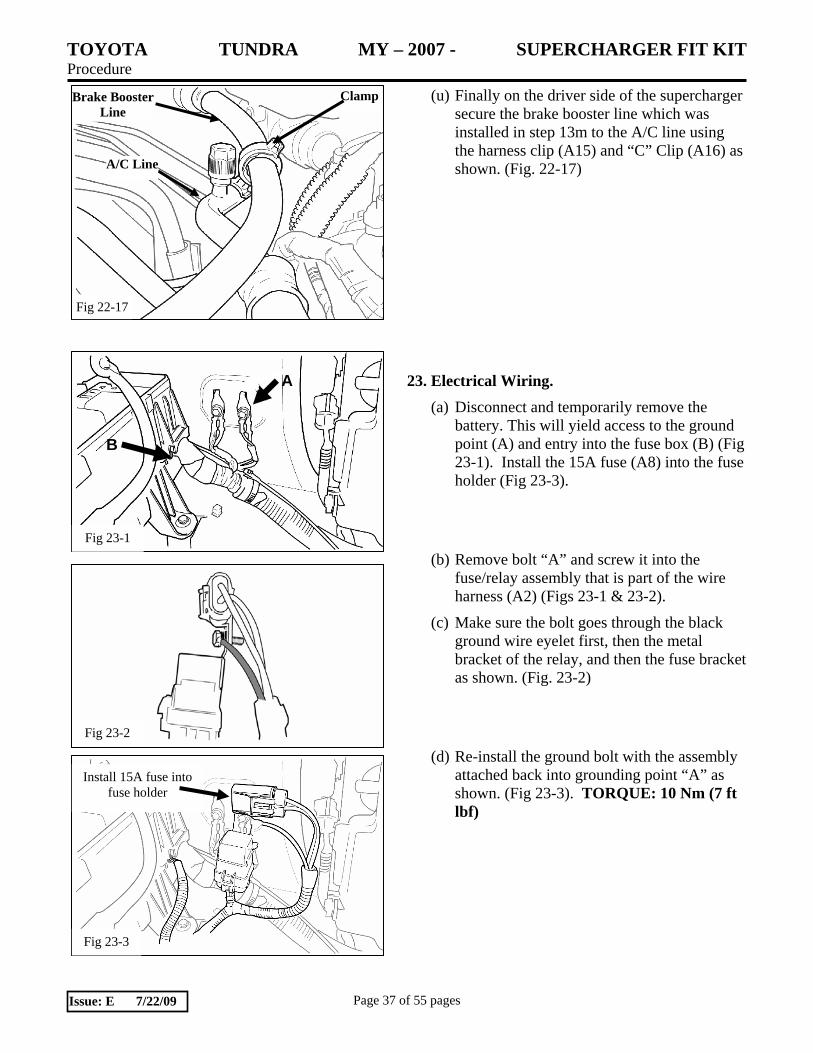
Fig 23-1
A
B
(u) Finally on the driver side of the supercharger secure the brake booster line which was installed in step 13m to the A/C line using the harness clip (A15) and “C” Clip (A16) as shown. (Fig. 22-17)
23. Electrical Wiring. (a) Disconnect and temporarily remove the
battery. This will yield access to the ground point (A) and entry into the fuse box (B) (Fig 23-1). Install the 15A fuse (A8) into the fuse holder (Fig 23-3).
(b) Remove bolt “A” and screw it into the fuse/relay assembly that is part of the wire harness (A2) (Figs 23-1 & 23-2).
(c) Make sure the bolt goes through the black ground wire eyelet first, then the metal bracket of the relay, and then the fuse bracket as shown. (Fig. 23-2)
(d) Re-install the ground bolt with the assembly attached back into grounding point “A” as shown. (Fig 23-3). TORQUE: 10 Nm (7 ft lbf)
Fig 23-2
Brake Booster Line
A/C Line
Clamp
Fig 22-17
Fig 23-3
Install 15A fuse into fuse holder

TOYOTA TUNDRA MY – 2007 - SUPERCHARGER FIT KIT Procedure
Page 38 of 55 pages Issue: E 7/22/09
Fig 23-5
Fig 23-7
Replacement Original
Fig 23-6
Fig 23-4
(e) Route the yellow wire of the relay wire harness (A2) into the vehicle fuse box through opening “C” (Figs 23-4).
(f) Remove the 10 amp ignition fuse (Figs 23-5 & 23-6). The original removed fuse and the new TRD replacement fuse (A8) are shown (Fig 23-7).

TOYOTA TUNDRA MY – 2007 - SUPERCHARGER FIT KIT Procedure
Page 39 of 55 pages Issue: E 7/22/09
Fig 23-8
Fig 23-9
Fuse Tap goes toward the rear of vehicle.
Fig 23-11
(g) The yellow wire that was fished up into the vehicle fuse box had a fuse tap on the end. Connect the fuse tap onto the new replacement fuse as shown (Fig 23-8).
(h) Insert the new fuse connected to the yellow wire in place of the removed fuse. The yellow wire side of the fuse goes toward the rear of the vehicle (Fig 23-9).
(i) Route the main length of the relay wire harness along the battery ground cable and secure using the short lock ties (A5) as shown (Fig 23-10). Also, add a short lock tie (A5) at the end of the cover over the yellow wire as shown.
(j) Route the red B+ wire of the relay wire harness up to the main battery B+ terminal and secure it with the plastic cover that clips to the cable (Fig 23-11).
Fig 23-10

TOYOTA TUNDRA MY – 2007 - SUPERCHARGER FIT KIT Procedure
Page 40 of 55 pages Issue: E 7/22/09
Fig 23-12
Fig 22-15
(k) Continue routing the wire harness along the intercooler hose on the driver’s side of the vehicle securing it with short lock ties (A5) as shown (Fig 23-12).
(l) Continue with the wire harness through the radiator bulkhead and down along the LTR (Fig 23-13). Secure with short lock ties (A5) as shown.
(m) Continue down and across the ¾” hose between the intercooler pump outlet and the LTR inlet (Fig 23-14).
(n) Secure with short lock ties (A5) as shown. (Fig. 23-14)
(o) Finally, route the end of the wire harness behind the intercooler pump inlet, down along the length of the pump and connect the electrical connector to the base of the pump (Fig 22-15).
(p) Re-attach front bumper assembly.
Fig 23-13
Fig 23-14

TOYOTA TUNDRA MY – 2007 - SUPERCHARGER FIT KIT Procedure
Page 41 of 55 pages Issue: E 7/22/09
24. OE In-Tank Fuel Pump Assembly Removal.
(a) Discharge fuel system pressure.
(b) Disconnect cable from negative battery terminal.
(c) Remove fuel tank cap.
(d) If required remove the fuel tank protector by removing the 2 bolts & 2 nuts as shown. (Fig. 24-1)
(e) Disconnect fuel tank feed and return tube sub-assemblies.
• Detach the lock claw by lifting up the cover as shown. (Fig. 24-2)
• Pinch and pull the main tube connector to disconnect the connector from the pipe. (Fig. 24-3)
NOTE: Do not force, bend or use tools when separating the tubes. Make sure all mating surfaces are clean. Do not kink the nylon fuel lines. If any kinks or other damage occurs during removal or installation of the fuel lines, then replacement of the damaged fuel line is REQUIRED.
(f) Disconnect the vent line hose by pulling up
on the retainer clip to disconnect as shown. (Fig. 24-4)
Fig 24-1
Fig 24-2
Fig 24-3
Fig 24-4
TOYOTA TUNDRA MY – 2007 - SUPERCHARGER FIT KIT Procedure
Page 42 of 55 pages Issue: E 7/22/09
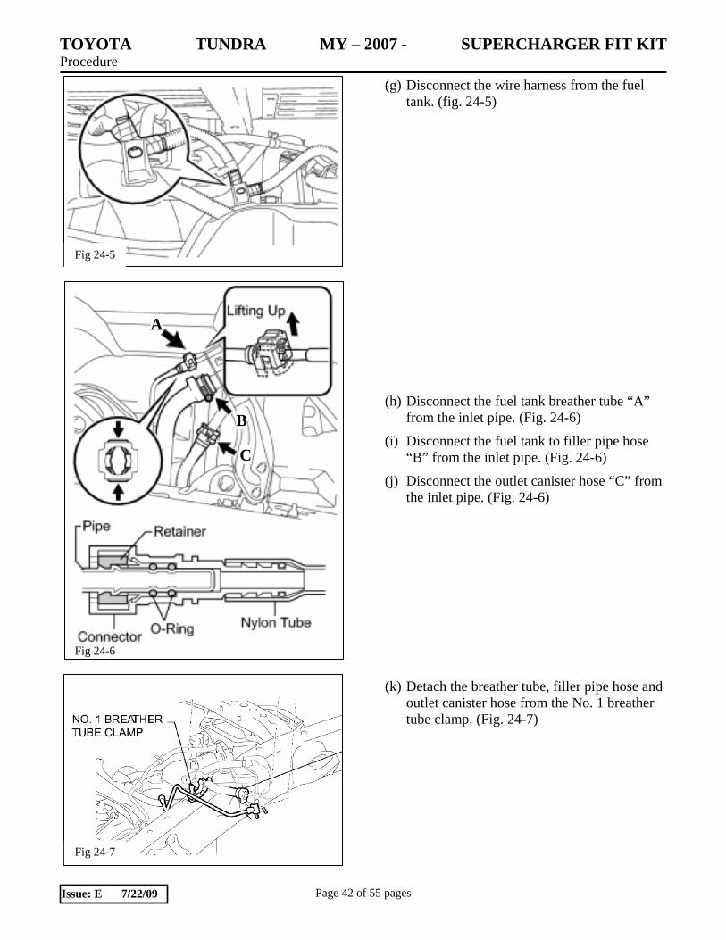
(g) Disconnect the wire harness from the fuel tank. (fig. 24-5)
(h) Disconnect the fuel tank breather tube “A” from the inlet pipe. (Fig. 24-6)
(i) Disconnect the fuel tank to filler pipe hose “B” from the inlet pipe. (Fig. 24-6)
(j) Disconnect the outlet canister hose “C” from the inlet pipe. (Fig. 24-6)
(k) Detach the breather tube, filler pipe hose and outlet canister hose from the No. 1 breather tube clamp. (Fig. 24-7)
Fig 24-5
A
B
C
Fig 24-6
Fig 24-7

TOYOTA TUNDRA MY – 2007 - SUPERCHARGER FIT KIT Procedure
Page 43 of 55 pages Issue: E 7/22/09
(l) Set a mission jack underneath the fuel tank.
(m) Remove the 2 bolts, 2 clips, 2 pins and 2 fuel tank bands. (Fig. 24-8)
(n) Slowly lower the fuel tank and disconnect the fuel pump connector. (Fig, 24-9)
(o) Slowly continue to lower the fuel tank to access the fuel pump assembly.
(p) Remove the 2 joint clips on the fuel tank tubes and then remove the tubes. (Fig. 24-10)
Fig 24-8
Fig 24-10
Fig 24-9

TOYOTA TUNDRA MY – 2007 - SUPERCHARGER FIT KIT Procedure
Page 44 of 55 pages Issue: E 7/22/09
(q) Using SST, loosen and remove the fuel pump retainer ring. (Fig. 24-11)
SST: 09808-14020 09080-01410 09080-01420 09080-01430
(r) Remove the fuel pump assembly from the fuel tank. (Fig. 24-12)
25. Remove Fuel Pump from Assembly
(a) Disconnect the fuel sender gauge connector.
(Fig. 25-1)
(b) Press down on the sender gauge claw labeled “A” and slide the sender gauge upward to remove. (Fig. 25-2)
Fig 24-11
Fig 24-12
Fig 25-1
Fig 25-2

TOYOTA TUNDRA MY – 2007 - SUPERCHARGER FIT KIT Procedure
Page 45 of 55 pages Issue: E 7/22/09
(c) Disconnect the fuel pump connector. (Fig. 25-3)
(d) Using a small screwdriver, detach the claw on the end of the tube from the claw hole. Disconnect the tube from the 2 clamps. (Fig. 25-4)
(e) Disconnect the fuel tube. (Fig. 25-5)
(f) Using a small screwdriver, detach the 3 claws from the claw holes. (Fig. 25-6)
Fig 25-3
Fig 25-4
Fig 25-6
Fig 25-5

TOYOTA TUNDRA MY – 2007 - SUPERCHARGER FIT KIT Procedure
Page 46 of 55 pages Issue: E 7/22/09
(g) Using a small screwdriver, detach the 2 claws from the claw holes and remove the sub tank. (Fig. 25-7)
(h) Using a small screwdriver, detach the 5 claws from the claw holes and disconnect the fuel pump from the suction plate with filter. (Fig. 25-8)
(i) Disconnect the fuel pump harness from the fuel pump. (Fig. 25-9)
(j) Remove the fuel pump discharge O-ring and spacer from the fuel pump. (Fig. 25-10)
Note: The old O-Ring can be discarded. A new fuel pump discharge O-Ring is included in the installation kit (J3). The spacer will be re-used with the new fuel pump.
Fig 25-7
Fig 25-8
Fig 25-9
Fig 25-10

TOYOTA TUNDRA MY – 2007 - SUPERCHARGER FIT KIT Procedure
Page 47 of 55 pages Issue: E 7/22/09
26. Install New Fuel Pump into Fuel Pump Assembly.
(a) Apply a light coat of gasoline to the new O-ring (J3). Then install the spacer and O-ring onto the fuel pump as shown. (Fig. 26-1)
Note: Make sure the new O-ring and spacer are installed as shown. Reversal of the o-ring and spacer will result in low fuel system pressure causing possible engine damage.
(b) Continue installing the new fuel pump into the fuel pump assembly in the exact opposite order used to remove the pump in step 25.
27. Re-install the Fuel Pump Assembly and Fuel Tank.
(a) Re-install the fuel pump assembly and fuel tank in the exact opposite order that was used during removal in step 24.
(b) Make sure you use the new Fuel Pump module O-Ring (J1) supplied in the kit when installing the fuel pump assembly into the fuel tank as shown. (Fig. 27-1).
(c) When re-installing the fuel tank assembly please use the torque specifications indicated in Fig. 27-2.
Fig 26-1
Fig 27-1
Fig 27-2 29 Nm/21 ft lbf 20 Nm/15 ft lbf
40 Nm/30 ft lbf

TOYOTA TUNDRA MY – 2007 - SUPERCHARGER FIT KIT Procedure
Page 48 of 55 pages Issue: E 7/22/09
28. Preparation for Vehicle Start-up. (a) Using the saved coolant from step 3 pour
coolant into the radiator until it is full. Hint:
• Use of improper coolant may damage the engine cooling system.
• Use Toyota Super Long Life Coolant or similar high quality ethylene glycol based non-silicate, non-amine, non-nitrate, and non-borate coolant with long-life hybrid organic acid technology.
• New Toyota vehicles are filled with Toyota Super Long Life Coolant (color is pink, premixed ethylene glycol concentration is approximately 50% and freezing temperature is -35°C (-31°F). When replacing and or adding coolant, Toyota Super Long Life Coolant is recommended.
NOTICE: Do not substitute plain water for engine coolant.
(b) Check the coolant level inside the radiator by squeezing the inlet and outlet radiator hoses several times by hand. If the coolant level goes down, add coolant.
(c) Install the radiator cap.
(d) Slowly pour coolant into the radiator reservoir until it reaches the FULL line.
(e) FILL THE INTERCOOLER RESERVOIR: Fill the intercooler reservoir with the same coolant as the vehicle radiator.
(f) Reinstall and connect the battery.
(g) Once the reservoir is full and will not take any more coolant, turn the ignition key to on, but do not start the engine. This will cause the intercooler pump to run and purge air from the intercooler system. Continue to add coolant to the reservoir until it is full.

TOYOTA TUNDRA MY – 2007 - SUPERCHARGER FIT KIT Procedure
Page 49 of 55 pages Issue: E 7/22/09
(h) Place the new vacuum and belt routing label (H8) on an open area under the hood (Fig 28 1). DO NOT cover the original vacuum hose label. Place the CARB OE Emissions label (H9) near the vacuum and belt routing label (Fig 27-1). Clean the area of any dirt and contaminants before adhering the labels.
(i) Install the Premium Fuel Only decals (H3). Place one on the dash near the fuel gauge AND one near the fuel filler cap.
(j) Prime the fuel system: You will need to prime the fuel lines and fuel rails before attempting to start the engine for the first time. Failure to do so will cause hard-starting for the first few tries, and may trigger false MIL lights.
(1) Using the TIS Techstream tool, connect to the vehicle and select the “ENG and ECT” ECU from the list of ECU’s.
(2) Select “Active Test” from the menu selection on the left of the screen.
(3) Select the test “Control the Fuel Pump/Speed” from the list of tests and click “OK”.
(4) You will see a data list, and a small window that tells the status of the fuel pump. Initially, the fuel pump will be “OFF”. Turn the fuel pump on and let it run for about 3 minutes. You can use this time to check for any fuel system leaks. When priming is complete, exit the test and prepare for ECU re-flashing.
NOTE: The fuel system priming function was written for use with TIS Techstream v4.12.001. If you do not have TIS Techstream, then consult with the manufacturer of the scan tool you are using to perform the fuel priming function.
Fig 28-1

TOYOTA TUNDRA MY – 2007 - SUPERCHARGER FIT KIT Procedure
Page 50 of 55 pages Issue: E 7/22/09
29. ECU Re-flash
(a) The proper procedure to re-flash the ECU
(Engine Control Unit) is explained in a
Technical Service Bulletin (SS002-07) titled
“Techstream ECU Flash Reprogramming
Procedure” located on T.I.S. (Toyota
Information System).
(b) Download your correct vehicle ECU
Calibration Update (See table below) from
TIS into the Toyota Techstream Tool using
the TIS Calibration Update Wizard.
(c) Follow the re-flashing procedure outlined in
T.S.B. SS002-07.
NOTE: Use Techstream v4.12.001 or later.
NOTE: The GR8 Battery Charger MUST
be used in Power Supply Mode to
maintain battery voltage at 13.5 volts
while flash reprogramming the vehicle.
For details on how to use the GR8 Battery
Charger please refer to the GR8
Instructions Manual located on TIS,
Diagnostics-Battery.
NOTE: The vehicle WILL NOT operate
properly without this ECU update.
TOYOTA TUNDRA MY – 2007 - SUPERCHARGER FIT KIT Procedure
Page 51 of 55 pages Issue: E 7/22/09
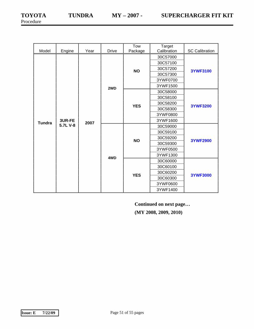
Model Engine Year Drive Tow
Package Target
Calibration SC Calibration 30C57000 30C57100 30C57200 30C57300 3YWF0700
NO
3YWF1500
3YWF3100
30C58000 30C58100 30C58200 30C58300 3YWF0800
2WD
YES
3YWF1600
3YWF3200
30C59000 30C59100 30C59200 30C59300 3YWF0500
NO
3YWF1300
3YWF2900
30C60000 30C60100 30C60200 30C60300 3YWF0600
Tundra 3UR-FE 5.7L V-8 2007
4WD
YES
3YWF1400
3YWF3000
Continued on next page…
(MY 2008, 2009, 2010)

TOYOTA TUNDRA MY – 2007 - SUPERCHARGER FIT KIT Procedure
Page 52 of 55 pages Issue: E 7/22/09
Model Engine Year Drive Tow
Package Target
Calibration SC Calibration 30C82000 30C82100 30C82200 30CA3000 30CA3100 3YWF0700
NO
3YWF1900
3YWF3500
30C83000 30C83100 30C83200 30CA4000 30CA4100 3YWF0800
2WD
YES
3YWF2000
3YWF3600
30C84000 30C84100 30C84200 30CA5000 30CA5100 3YWF0500
NO
3YWF1700
3YWF3300
30C85000 30C85100 30C85200 30CA6000 30CA6100 3YWF0600
2008
4WD
YES
3YWF1800
3YWF3400
30CA3000 NO
30CA3100 3YWF2300
30CA4000 2WD
YES 30CA4100
3YWF2400
30CA5000 NO
30CA5100 3YWF2100
30CA6000
2009
4WD
YES 30CA6100
3YWF2200
NO 30CD0000 3YWF2700 2WD
YES 30CD1000 3YWF2800 NO 30CD2000 3YWF2500
Tundra 3UR-FE 5.7L V-8
2010 4WD
YES 30CD3000 3YWF2600

TOYOTA TUNDRA MY – 2007 - SUPERCHARGER FIT KIT Procedure
Page 53 of 55 pages Issue: E 7/22/09
30. Testing and Evaluation.
(a) IMPORTANT: Check the serpentine belt drive systems for correct alignment on ALL pulleys before starting the engine.
(b) Start the engine and let it idle.
(c) Check the fuel system for any leaks.
(d) Check the coolant system for any leaks.
(i) Set the A/C system as follows:
Fan Speed Any setting except OFF
Temperature Toward Warm
A/C Switch OFF
(ii) Maintain the engine speed at 2,000 to 2,500 rpm and warm up the engine until the cooling fan operates.
(iii) Squeeze the inlet and outlet radiator hoses several times by hand while warming up the engine.
(e) Check the air intake system to ensure there are no leaks and for tightness.
(f) Stop the engine and wait for the coolant to cool down.
(g) Carefully remove the radiator cap and check the coolant level inside the radiator and add coolant if necessary. Reinstall the radiator cap.
(h) Check the coolant level inside the radiator reservoir. If it is below the full level, add coolant.
(i) Check the coolant in the intercooler reservoir and add coolant if necessary.
(j) Drive test the vehicle. If all is okay, park and proceed with the next step. If not, troubleshoot as necessary.

TOYOTA TUNDRA MY – 2007 - SUPERCHARGER FIT KIT Procedure
Page 54 of 55 pages Issue: E 7/22/09
(k) Use the diagnostic TechStream tool to check for ECU error codes.
(l) Place the Supercharger noise Mirror hanger card (H7) on the inside rearview mirror.
(m) Complete and mail the warranty registration card (H6). Note: The installation of the Supercharger is not complete until this card has been returned to TRD.
(n) Place all removed factory hardware, components, and this instruction sheet into the original TRD kit box and give it to the customer and or place it in the vehicle cargo compartment.
(o) IMPORTANT: Review with the customer/end-user that the supercharger will make a slight noise at idle that increases as the throttle is opened and that this is normal.
(p) IMPORTANT: Review with the customer/end-user that it is it is imperative that only 91octane or higher fuel be used after the supercharger is installed. Performance will suffer and engine damage is possible otherwise.

TOYOTA TUNDRA MY 2007 - SUPERCHARGER FIT KIT Checklist - these points MUST be checked to ensure a quality installation.
Check: Look For:
Page 55 of 55 pages Issue: E 7/22/09
Accessory Function Checks
Use of 91 Octane Fuel (R+M / 2)
All Fluid Levels & Leaks
Serpentine belt alignment
Fuel Line connections
Engine Fan Clutch Clearance
Engine ECU Reflash
Vehicle Function Checks
Fuel leak
Coolant leak
Drive test
Use 91 Octane Unleaded Fuel (R+M /2)
Inspect Engine Cooling System and
Supercharger Cooling System for Proper
Fluid Type and Level.
Inspect Serpentine Belt Drive Belts for
Proper Alignment, Tension, and Clearance
from Engine Compartment Items.
Inspect all Fuel Rails, Injectors, Injector
Seals, Pressure Regulator, and Fuel Line
Connectors for Leaks.
Inspect Engine Fan Clutch for Free
Movement and Clearance from Radiator.
Ensure the Proper Calibration File was used
for the Vehicle.
No Fuel leaks are present
No coolant leaks are present
Vehicle starts Up Easily, No DTC Trouble
Codes are Present, Drivability is Smooth
and Predictable.