T&M solutions for software defined radios (SDR) · Software defined radio (SDR) 1MA206_3e Rohde &...
57
T&M solutions for software defined radios (SDR) This document provides an introduction to Software Defined Radio (SDR) as used for military radios and presents the relevant T&M solutions offered by Rohde & Schwarz. Note: Please find the most up-to-date document on our homepage https://www.rohde-schwarz.com/appnote/1MA206 Bernhard Schulz July 2018 -1MA206_3e
Transcript of T&M solutions for software defined radios (SDR) · Software defined radio (SDR) 1MA206_3e Rohde &...
T&M solutions for software defined radios (SDR)
This document provides an introduction to
Software Defined Radio (SDR) as used for
military radios and presents the relevant
T&M solutions offered by Rohde &
Schwarz.
Note: Please find the most up-to-date document on our homepage https://www.rohde-schwarz.com/appnote/1MA206
Ber
nhar
d S
chul
z
July
201
8 -1
MA
206_
3e
Table of Contents
1MA206_3e Rohde & Schwarz SDR Measurements 2
Table of Contents
1 Introduction ............................................................................ 5
1.1 Software defined radio (SDR) ...................................................................... 5
1.2 Requirements for military radios ................................................................ 7
1.3 Waveforms and measurement parameters ................................................ 8
1.3.1 Waveforms .................................................................................................... 8
1.3.2 Test parameters ............................................................................................ 9
1.4 SDRs from Rohde & Schwarz ...................................................................12
2 T&M solutions in development, production and service .. 15
2.1 Measurements in the RF and IF range .....................................................18
2.1.1 Transmitter tests: Signal and spectrum analyzer ...................................18
2.1.2 Receiver tests: Signal generators ............................................................25
2.1.3 Local oscillator (LO) performance ............................................................29
2.1.4 Amplifier measurements ...........................................................................31
2.1.5 Filter / mixer measurements ......................................................................33
2.1.6 Analog-to-digital converter (ADC) measurements ..................................35
2.1.7 Antennas .....................................................................................................37
2.2 Measurements in and on the digital baseband .......................................38
2.2.1 Communications bus measurements: Oscilloscopes ...........................39
2.2.2 Connection to the digital I/Q interface (EX-IQ-Box) ................................40
2.2.3 Measurements at the audio interface .......................................................40
2.3 EMC tests ....................................................................................................41
2.4 Test system for production, verification and maintenance ...................42
2.5 Channel simulator: fading .........................................................................47
2.6 CMA180 Radio Test Set .............................................................................49
2.7 CTH: On-site service ..................................................................................51
2.8 Instrument integration in EDA tools .........................................................52
3 Appendix ............................................................................... 53
3.1 Literature .....................................................................................................53
3.2 Additional information ...............................................................................54
3.3 Ordering information .................................................................................54
Table of Contents
1MA206_3e Rohde & Schwarz SDR Measurements 3
The following abbreviations are used in this application note for Rohde & Schwarz test equipment:
The R&S®SMW200A is referred to as the SMW.
The R&S®SMBV100A is referred to as the SMBV.
The R&S®AFQ100A/B is referred to as the AFQ.
The R&S®Ex-IQ-Box is referred to as the Ex-IQ-Box.
The R&S®SMA100A/B is referred to as the SMA.
The R&S®SMB100A/B is referred to as the SMB.
The R&S®SMC100A is referred to as the SMC.
The R&S®SMF100A is referred to as the SMF.
The R&S®SGS100A is referred to as the SGS.
The R&S®FSV is referred to as the FSV.
The R&S®FSW is referred to as the FSW.
The R&S®FSVR is referred to as the FSVR.
The R&S®FPS is referred to as the FPS.
The R&S®FPC is referred to as the FPC.
The R&S®FPL is referred to as the FPL.
The R&S®FSL is referred to as the FSL.
The R&S®FSH4/8 is referred to as the FSH.
The R&S®FPH is referred to as the FPH. All analyzers are referred to as the FSx.
The R&S®ZVA is referred to as the ZVA.
The R&S®ZVT is referred to as the ZVT.
The R&S®ZNBT is referred to as the ZNBT.
The R&S®ZNL is referred to as the ZNL.
The R&S®ZNLE is referred to as the ZNLE.
The R&S®ZNC is referred to as the ZNC.
The R&S®ZND is referred to as the ZND.
The R&S®ZVL is referred to as the ZVL.
The R&S®ZPL is referred to as the ZNH.
The R&S®ESW is referred to as the ESW
The R&S®ESR is referred to as the ESR.
The R&S®ESRP is referred to as the ESRP.
The R&S®ESL is referred to as the ESL.
The R&S®RTP is referred to as the RTP.
The R&S®RTO is referred to as the RTO.
The R&S®RTE is referred to as the RTE.
The R&S®RTA is referred to as the RTA.
The R&S®RTM is referred to as the RTM.
The R&S®RTB is referred to as the RTB.
The R&S®RTC is referred to as the RTC.
All oscilloscopes are referred to as the RTx.
The R&S®CTH100A/200A is referred to as CTH.
The R&S®CMA18 is referred to as CMA.

Table of Contents
1MA206_3e Rohde & Schwarz SDR Measurements 4
The R&S®SECOS waveforms are referred as SECOS.
The R&S®SECOM waveforms are referred as SECOM.
The R&S®HDR waveforms are referred as HDR.
The R&S®MR6000A is referred as MR6000A.
The R&S®MR6000L/R is referred as MR6000L/R.
The R&S®MR6000E is referred as MR6000E.
All airborne radios are referred as M3AR.
The R&S®M3SR Series 4100 is referred as Series 4100.
The R&S®M3SR Series 4400 is referred as Series 4400.
All stationary/shipborne radios are referred as M3SR.
The R&S®Series 4200 is referred as Series 4200.
The R&S®MR3000P is referred as MR3000P.
The R&S®MR300xU/H is referred as MR300xU/H.
All tactical radios are referred as M3TR.
All proprietary SDR radios are referred as M3xR.
The R&S®SDAR AR5000 is referred as SDAR.
The R&S®SDTR VR5000 is referred as SDTR.
All SCA based SDR raios are referred as SDxR.
Introduction
Software defined radio (SDR)
1MA206_3e Rohde & Schwarz SDR Measurements 5
1 Introduction When only analog radio engineering was available, radios were completely based on
hardware. Even with the introduction of digital radio standards, radios remained
hardware based and therefore were highly suited to a single radio technology.
Why SDR?
It was not long before consumers wanted radios that could handle multiple radio
standards. For example, frequent travelers were already requesting mobile phones that
could handle more than one radio standard at the time that GSM and CDMA were in
use in commercial applications. Any state-of-the-art, commercially available mobile
phone now supports at a minimum several standards, including LTE, W-CDMA, GSM,
Bluetooth® and WLAN.
One way of doing this is to use multiple hardware configurations, each specifically
adapted to a radio standard, although this method increases costs drastically. A radio
that can be (re)configured using software is an ideal solution.
The term “software defined radio” is not clearly defined. Its definition differs depending
on the author and the field of application. The Wireless Innovation Forum defines SDR
as follows: “Radio in which some or all of the physical layer functions are software
defined”
This white paper presents the basic idea behind SDR and provides an overview of the
Rohde & Schwarz radios. Chapter 2 presents the T&M solutions offered by Rohde &
Schwarz.
1.1 Software defined radio (SDR)
From analog radios to software defined radio
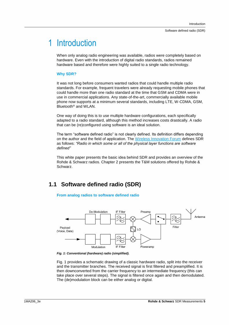
Fig. 1: Conventional (hardware) radio (simplified).
Fig. 1 provides a schematic drawing of a classic hardware radio, split into the receiver and the transmitter branches. The received signal is first filtered and preamplified. It is then downconverted from the carrier frequency to an intermediate frequency (this can take place over several steps). The signal is filtered once again and then demodulated. The (de)modulation block can be either analog or digital.
Introduction
Software defined radio (SDR)
1MA206_3e Rohde & Schwarz SDR Measurements 6
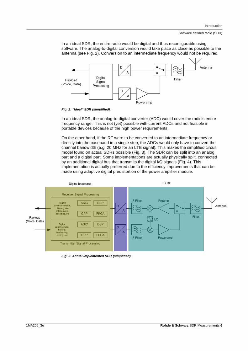
In an ideal SDR, the entire radio would be digital and thus reconfigurable using software. The analog-to-digital conversion would take place as close as possible to the antenna (see Fig. 2). Conversion to an intermediate frequency would not be required.
Fig. 2: “Ideal” SDR (simplified).
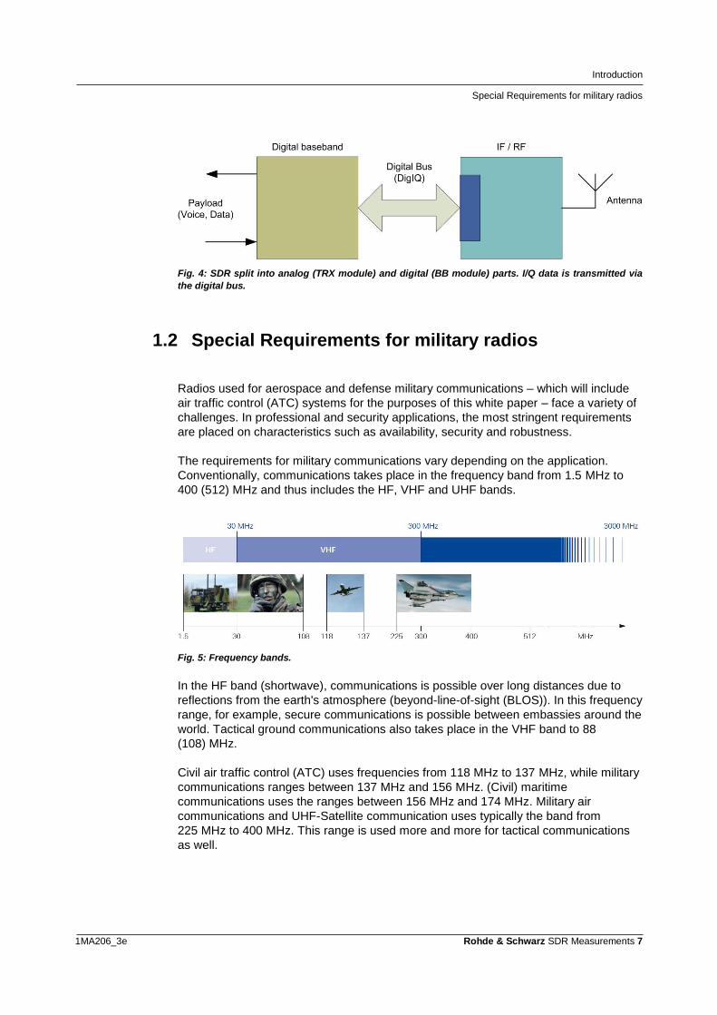
In an ideal SDR, the analog-to-digital converter (ADC) would cover the radio's entire frequency range. This is not (yet) possible with current ADCs and not feasible in portable devices because of the high power requirements. On the other hand, if the RF were to be converted to an intermediate frequency or directly into the baseband in a single step, the ADCs would only have to convert the channel bandwidth (e.g. 20 MHz for an LTE signal). This makes the simplified circuit model found on actual SDRs possible (Fig. 3). The SDR can be split into an analog part and a digital part. Some implementations are actually physically split, connected by an additional digital bus that transmits the digital I/Q signals (Fig. 4). This implementation is actually preferred due to the efficiency improvements that can be made using adaptive digital predistortion of the power amplifier module.
Fig. 3: Actual implemented SDR (simplified).
Introduction
Special Requirements for military radios
1MA206_3e Rohde & Schwarz SDR Measurements 7
Fig. 4: SDR split into analog (TRX module) and digital (BB module) parts. I/Q data is transmitted via
the digital bus.
1.2 Special Requirements for military radios
Radios used for aerospace and defense military communications – which will include
air traffic control (ATC) systems for the purposes of this white paper – face a variety of
challenges. In professional and security applications, the most stringent requirements
are placed on characteristics such as availability, security and robustness.
The requirements for military communications vary depending on the application.
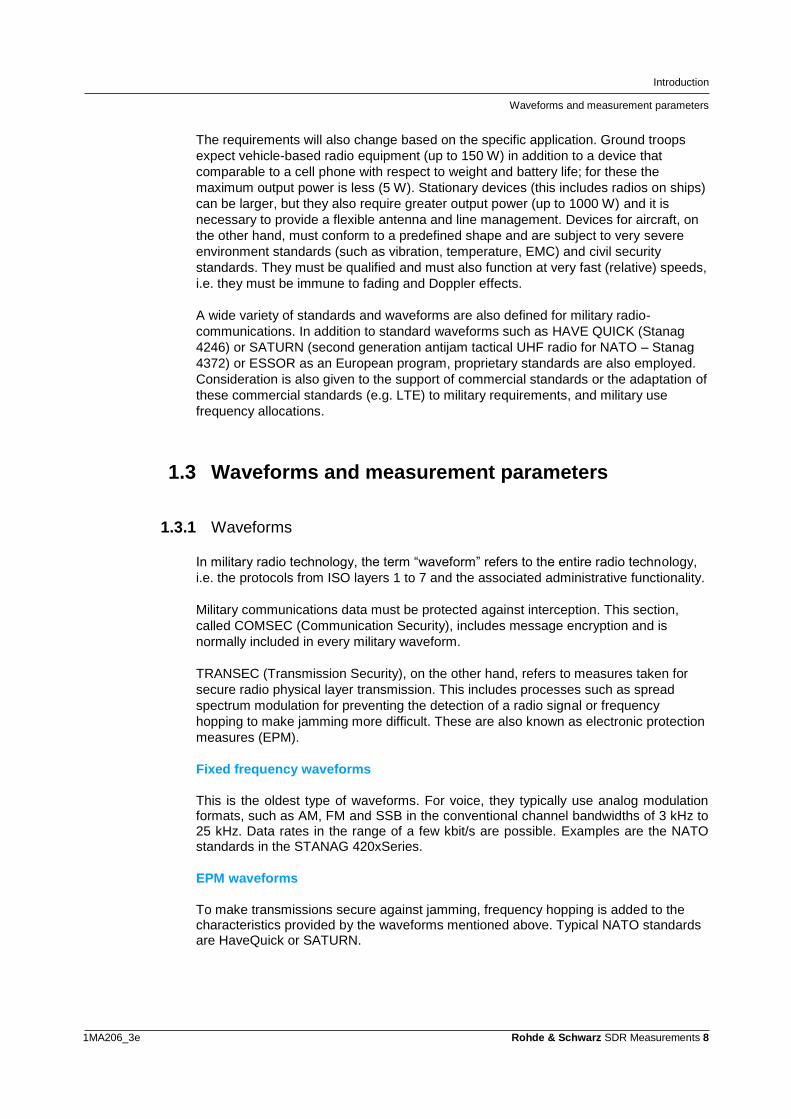
Conventionally, communications takes place in the frequency band from 1.5 MHz to
400 (512) MHz and thus includes the HF, VHF and UHF bands.
Fig. 5: Frequency bands.
In the HF band (shortwave), communications is possible over long distances due to
reflections from the earth's atmosphere (beyond-line-of-sight (BLOS)). In this frequency
range, for example, secure communications is possible between embassies around the
world. Tactical ground communications also takes place in the VHF band to 88
(108) MHz.
Civil air traffic control (ATC) uses frequencies from 118 MHz to 137 MHz, while military
communications ranges between 137 MHz and 156 MHz. (Civil) maritime
communications uses the ranges between 156 MHz and 174 MHz. Military air
communications and UHF-Satellite communication uses typically the band from
225 MHz to 400 MHz. This range is used more and more for tactical communications
as well.
Introduction
Waveforms and measurement parameters
1MA206_3e Rohde & Schwarz SDR Measurements 8
The requirements will also change based on the specific application. Ground troops
expect vehicle-based radio equipment (up to 150 W) in addition to a device that
comparable to a cell phone with respect to weight and battery life; for these the
maximum output power is less (5 W). Stationary devices (this includes radios on ships)
can be larger, but they also require greater output power (up to 1000 W) and it is
necessary to provide a flexible antenna and line management. Devices for aircraft, on
the other hand, must conform to a predefined shape and are subject to very severe
environment standards (such as vibration, temperature, EMC) and civil security
standards. They must be qualified and must also function at very fast (relative) speeds,
i.e. they must be immune to fading and Doppler effects.
A wide variety of standards and waveforms are also defined for military radio-
communications. In addition to standard waveforms such as HAVE QUICK (Stanag
4246) or SATURN (second generation antijam tactical UHF radio for NATO – Stanag
4372) or ESSOR as an European program, proprietary standards are also employed.
Consideration is also given to the support of commercial standards or the adaptation of
these commercial standards (e.g. LTE) to military requirements, and military use
frequency allocations.
1.3 Waveforms and measurement parameters
1.3.1 Waveforms
In military radio technology, the term “waveform” refers to the entire radio technology,
i.e. the protocols from ISO layers 1 to 7 and the associated administrative functionality.
Military communications data must be protected against interception. This section,
called COMSEC (Communication Security), includes message encryption and is
normally included in every military waveform.
TRANSEC (Transmission Security), on the other hand, refers to measures taken for
secure radio physical layer transmission. This includes processes such as spread
spectrum modulation for preventing the detection of a radio signal or frequency
hopping to make jamming more difficult. These are also known as electronic protection
measures (EPM).
Fixed frequency waveforms
This is the oldest type of waveforms. For voice, they typically use analog modulation formats, such as AM, FM and SSB in the conventional channel bandwidths of 3 kHz to 25 kHz. Data rates in the range of a few kbit/s are possible. Examples are the NATO standards in the STANAG 420xSeries.
EPM waveforms
To make transmissions secure against jamming, frequency hopping is added to the characteristics provided by the waveforms mentioned above. Typical NATO standards are HaveQuick or SATURN.
Introduction
Waveforms and measurement parameters
1MA206_3e Rohde & Schwarz SDR Measurements 9
HF waveforms
The main purpose of beyond-line-of-sight (BLOS) is to be able to have long reach back
without the need for infrastructure. The main advantage of HF radiocommunications is
the fact that the electromagnetic signals between 1.5 MHz and 30 MHz allow to use
reflection effects on the ionosphere to achieve extremely high ranges of thousands of
kilometers without any infrastructure between transmitter and receiver.
Tactical data links
Tactical data links go beyond simple waveforms and form systems for networking entire units, e.g. to provide position data. A TDMA (Time-Division Multiple Access) mode is being introduced to allow access by many users. The channel bandwidths increase, higher digital modulation modes are used and the data rates are in the range of 100 kbit/s. Examples are Link 16 or Link 22.
Proprietary and future waveforms
In addition, various manufacturers offer proprietary waveforms with COMSEC and TRANSEC. For example, Rohde & Schwarz provides the waveforms SECOS, SECOM and the modern HDR family. HDR waveforms: • R&S HDR-WB: Mobile networked, high data rates, medium range. • R&S HDR-AJ-WB: Mobile networked, medium data rates, medium to high
range, high jamming immunity. • R&S HDR-AJ-NB: Best possible data rate in tactical VHF band, best possible
range, high jamming immunity, low spectrum requirements. There has been an increasing demand for rapid data transmission in the military arena as well. Future waveforms in the UHF band should achieve data rates of 10 Mbit/s. Consideration is also given to the adaptation of commercial standards (e.g. LTE) for tactical networks.
1.3.2 Test parameters
Some of the radio test and measurement requirements are covered by the
conventional parameters, such as power and modulation. As early as 1993, NATO had
already defined and standardized an international test operations procedure (ITOP) for
fixed-frequency analog radios [1]. Requirements like spectrum masks are defined in
relevant specifications (NATO STANAGs). ITOP provides extremely detailed
descriptions of measurements and also defines test setups. It describes the following
tests:
Introduction
Waveforms and measurement parameters
1MA206_3e Rohde & Schwarz SDR Measurements 10
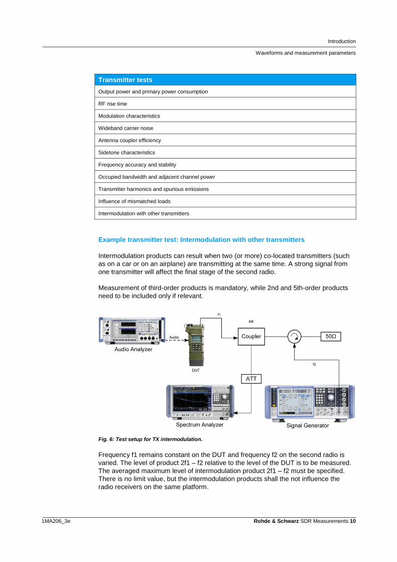
Transmitter tests
Output power and primary power consumption
RF rise time
Modulation characteristics
Wideband carrier noise
Antenna coupler efficiency
Sidetone characteristics
Frequency accuracy and stability
Occupied bandwidth and adjacent channel power
Transmitter harmonics and spurious emissions
Influence of mismatched loads
Intermodulation with other transmitters
Example transmitter test: Intermodulation with other transmitters
Intermodulation products can result when two (or more) co-located transmitters (such
as on a car or on an airplane) are transmitting at the same time. A strong signal from
one transmitter will affect the final stage of the second radio.
Measurement of third-order products is mandatory, while 2nd and 5th-order products
need to be included only if relevant.
Fig. 6: Test setup for TX intermodulation.
Frequency f1 remains constant on the DUT and frequency f2 on the second radio is
varied. The level of product 2f1 – f2 relative to the level of the DUT is to be measured.
The averaged maximum level of intermodulation product 2f1 – f2 must be specified.
There is no limit value, but the intermodulation products shall the not influence the
radio receivers on the same platform.
Introduction
Waveforms and measurement parameters
1MA206_3e Rohde & Schwarz SDR Measurements 11
Receiver tests
Receiver sensitivity and associated characteristics
Demodulation characteristics
Dynamic sensitivity and desensitization
Spurious response and IF rejection
Intermodulation response (out of band)
Blocking
Oscillator emission
Cross modulation rejection
Receiver response time
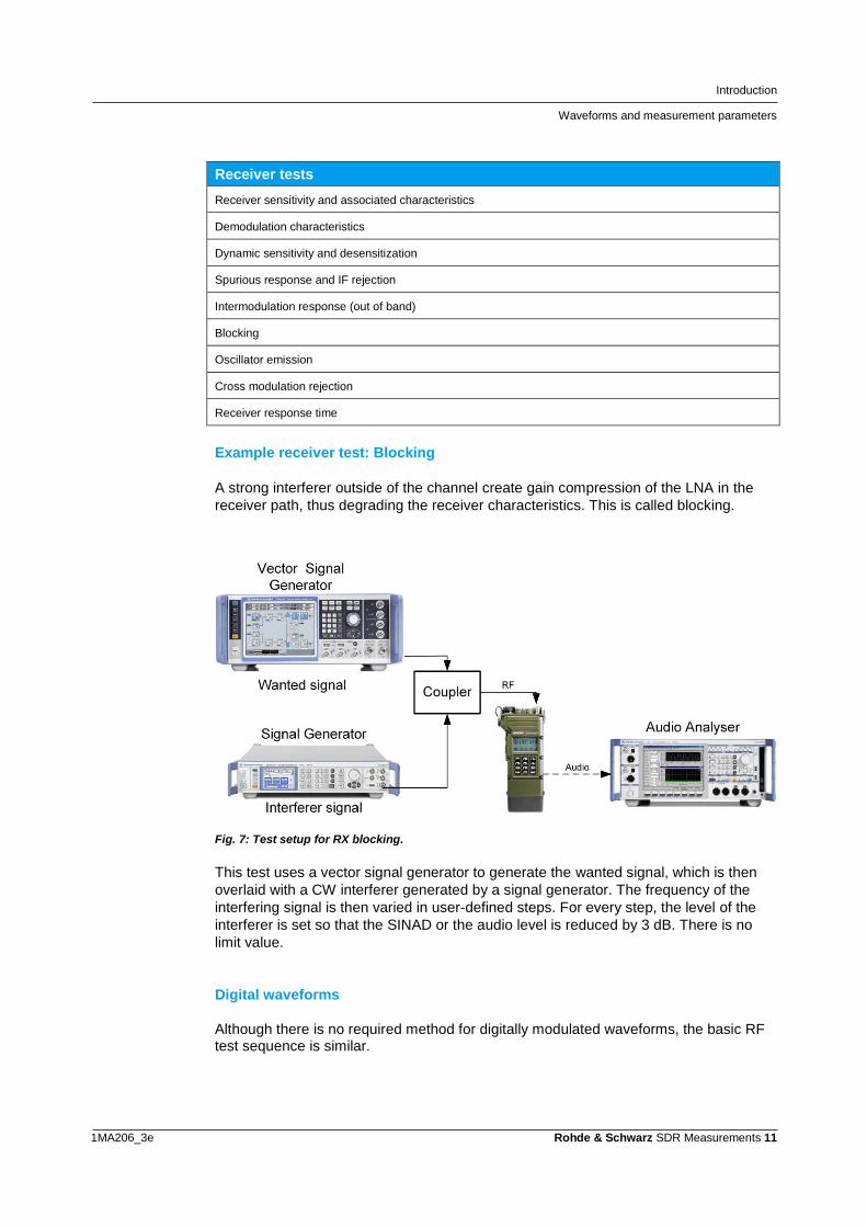
Example receiver test: Blocking
A strong interferer outside of the channel create gain compression of the LNA in the
receiver path, thus degrading the receiver characteristics. This is called blocking.
Fig. 7: Test setup for RX blocking.
This test uses a vector signal generator to generate the wanted signal, which is then
overlaid with a CW interferer generated by a signal generator. The frequency of the
interfering signal is then varied in user-defined steps. For every step, the level of the
interferer is set so that the SINAD or the audio level is reduced by 3 dB. There is no
limit value.
Digital waveforms
Although there is no required method for digitally modulated waveforms, the basic RF test sequence is similar.
Introduction
SDRs from Rohde & Schwarz
1MA206_3e Rohde & Schwarz SDR Measurements 12
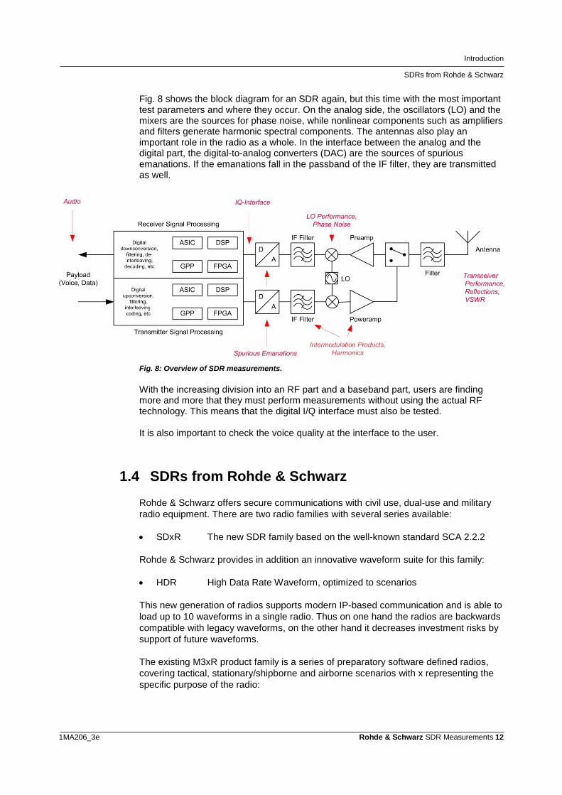
Fig. 8 shows the block diagram for an SDR again, but this time with the most important test parameters and where they occur. On the analog side, the oscillators (LO) and the mixers are the sources for phase noise, while nonlinear components such as amplifiers and filters generate harmonic spectral components. The antennas also play an important role in the radio as a whole. In the interface between the analog and the digital part, the digital-to-analog converters (DAC) are the sources of spurious emanations. If the emanations fall in the passband of the IF filter, they are transmitted as well.
Fig. 8: Overview of SDR measurements.
With the increasing division into an RF part and a baseband part, users are finding more and more that they must perform measurements without using the actual RF technology. This means that the digital I/Q interface must also be tested. It is also important to check the voice quality at the interface to the user.
1.4 SDRs from Rohde & Schwarz
Rohde & Schwarz offers secure communications with civil use, dual-use and military
radio equipment. There are two radio families with several series available:
SDxR The new SDR family based on the well-known standard SCA 2.2.2
Rohde & Schwarz provides in addition an innovative waveform suite for this family:
HDR High Data Rate Waveform, optimized to scenarios
This new generation of radios supports modern IP-based communication and is able to
load up to 10 waveforms in a single radio. Thus on one hand the radios are backwards
compatible with legacy waveforms, on the other hand it decreases investment risks by
support of future waveforms.
The existing M3xR product family is a series of preparatory software defined radios,
covering tactical, stationary/shipborne and airborne scenarios with x representing the
specific purpose of the radio:
Introduction
SDRs from Rohde & Schwarz
1MA206_3e Rohde & Schwarz SDR Measurements 13
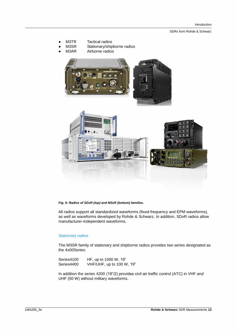
● M3TR Tactical radios
● M3SR Stationary/shipborne radios
● M3AR Airborne radios
Fig. 9: Radios of SDxR (top) and M3xR (bottom) families.
All radios support all standardized waveforms (fixed-frequency and EPM waveforms),
as well as waveforms developed by Rohde & Schwarz. In addition, SDxR radios allow
manufacturer-independent waveforms.
Stationary radios
The M3SR family of stationary and shipborne radios provides two series designated as
the 4x00Series:
Series4100 HF, up to 1000 W, 19”
Series4400 VHF/UHF, up to 100 W, 19”
In addition the series 4200 (19“/2) provides civil air traffic control (ATC) in VHF and
UHF (50 W) without military waveforms.
Introduction
SDRs from Rohde & Schwarz
1MA206_3e Rohde & Schwarz SDR Measurements 14
Airborne radios
The airborne radios are represented by the M3AR MR6000 family of radios with three
series, with power from 20 W /AM and 30 W / FM. These radios support military and
civil ATC and are approved in various configurations for jet and propeller aircraft, as
well as for helicopters and unmanned aircraft (drones).
Series MR6000L/R tact. VHF/VHF/UHF, 10 W, ARC 164
Series MR6000A tact. VHF/VHF/UHF, 20 W, ARINC 600
Series MR6000E VHF/UHF, 10 W, special L-Shape for Eurofighter
Latest member is the SDAR radio in the SDxR family:
Series AR5000 tact. VHF/VHF/UHF, 20 W, ARINC 600
Tactical radios
The SDTR is the latest tactical radio of the der SDxR-familiy:
SDTR Vehicular and semi-mobile, 30 MHz…512 MHz, 50 W without external
PA
The M3TR MR300x family of radios is available in various configurations, ranging from
handheld devices to onboard equipment in automobiles:
● MR3000P Handheld, 25 MHz to 146 MHz, 5 W
● MR300xH Manpack, 1.5 MHz to 108 MHz, 10 W (VHF), 20 W (HF)
● MR300xU Manpack, 25 MHz to 512 MHz, 10 W (VHF/UHF)
In addition, there are many options available, e.g. external Pas for 50 W in VHF/UHF
and up to 500 W in HF. Additional information about the M3xR family of radios is available on our Website.
T&M solutions in development, production and service
SDRs from Rohde & Schwarz
1MA206_3e Rohde & Schwarz SDR Measurements 15
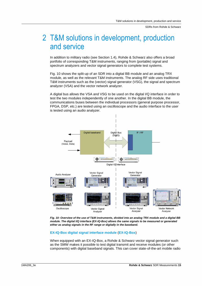
2 T&M solutions in development, production and service In addition to military radio (see Section 1.4), Rohde & Schwarz also offers a broad
portfolio of corresponding T&M instruments, ranging from (portable) signal and
spectrum analyzers and vector signal generators to complete test systems.
Fig. 10 shows the split-up of an SDR into a digital BB module and an analog TRX
module, as well as the relevant T&M instruments. The analog RF side uses traditional
T&M instruments such as the (vector) signal generator (VSG), the signal and spectrum
analyzer (VSA) and the vector network analyzer.
A digital bus allows the VSA and VSG to be used on the digital I/Q interface in order to
test the two modules independently of one another. In the digital BB module, the
communications buses between the individual processors (general purpose processor,
FPGA, DSP, etc.) are tested using an oscilloscope and the audio interface to the user
is tested using an audio analyzer.
Fig. 10: Overview of the use of T&M instruments, divided into an analog TRX module and a digital BB
module. The digital I/Q interface (EX-IQ-Box) allows the same signals to be measured or generated
either as analog signals in the RF range or digitally in the baseband.
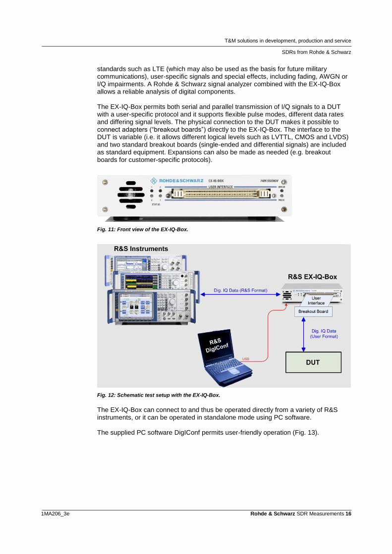
EX-IQ-Box digital signal interface module (EX-IQ-Box)
When equipped with an EX-IQ-Box, a Rohde & Schwarz vector signal generator such as the SMW makes it possible to test digital transmit and receive modules (or other components) with digital baseband signals. This can cover state-of-the-art mobile radio
T&M solutions in development, production and service
SDRs from Rohde & Schwarz
1MA206_3e Rohde & Schwarz SDR Measurements 16
standards such as LTE (which may also be used as the basis for future military communications), user-specific signals and special effects, including fading, AWGN or I/Q impairments. A Rohde & Schwarz signal analyzer combined with the EX-IQ-Box allows a reliable analysis of digital components. The EX-IQ-Box permits both serial and parallel transmission of I/Q signals to a DUT with a user-specific protocol and it supports flexible pulse modes, different data rates and differing signal levels. The physical connection to the DUT makes it possible to connect adapters (“breakout boards”) directly to the EX-IQ-Box. The interface to the DUT is variable (i.e. it allows different logical levels such as LVTTL, CMOS and LVDS) and two standard breakout boards (single-ended and differential signals) are included as standard equipment. Expansions can also be made as needed (e.g. breakout boards for customer-specific protocols).
Fig. 11: Front view of the EX-IQ-Box.
Fig. 12: Schematic test setup with the EX-IQ-Box.
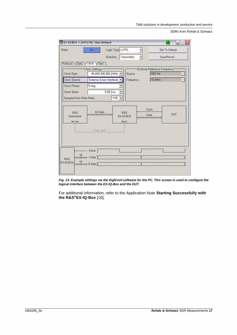
The EX-IQ-Box can connect to and thus be operated directly from a variety of R&S instruments, or it can be operated in standalone mode using PC software. The supplied PC software DigIConf permits user-friendly operation (Fig. 13).
T&M solutions in development, production and service
SDRs from Rohde & Schwarz
1MA206_3e Rohde & Schwarz SDR Measurements 17
Fig. 13: Example settings via the DigIConf software for the PC. This screen is used to configure the
logical interface between the EX-IQ-Box and the DUT.
For additional information, refer to the Application Note Starting Successfully with the R&S®EX-IQ-Box [16].
T&M solutions in development, production and service
Measurements in the RF and IF range
1MA206_3e Rohde & Schwarz SDR Measurements 18
2.1 Measurements in the RF and IF range
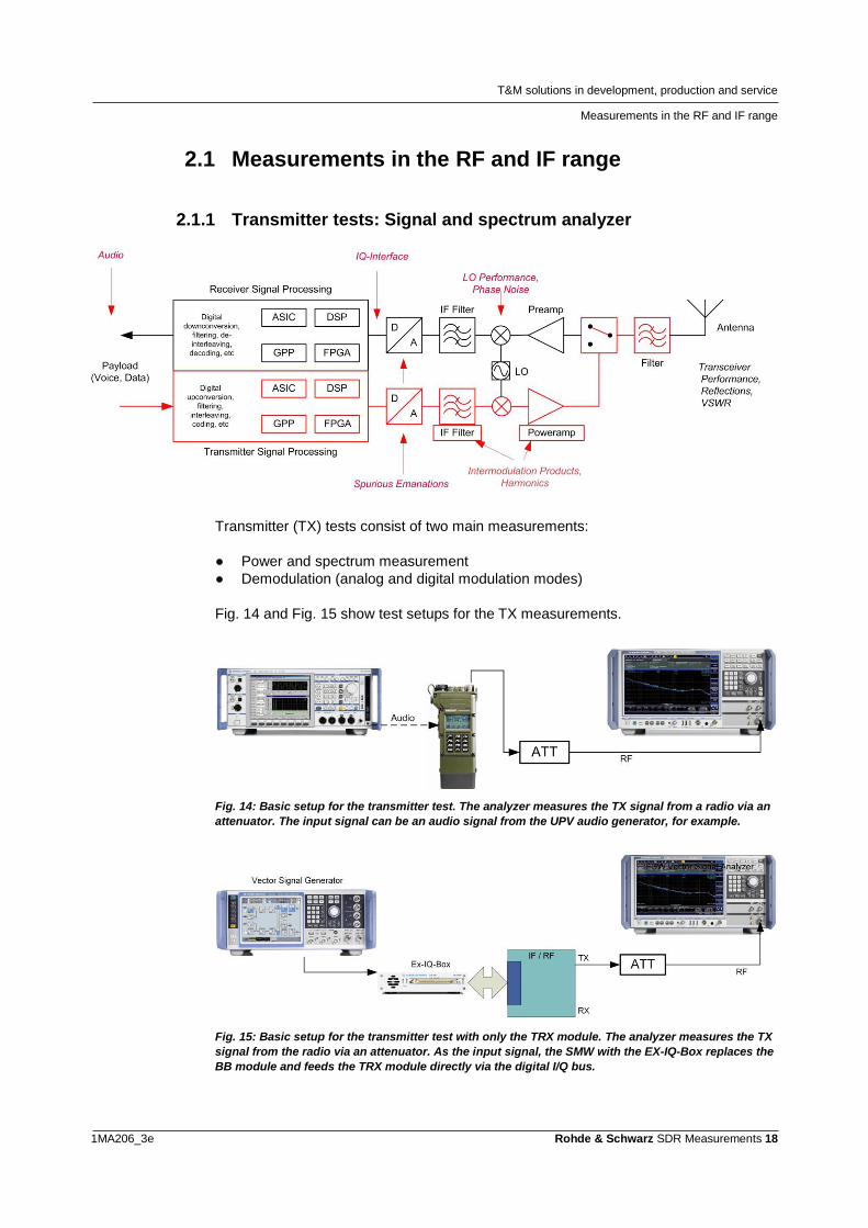
2.1.1 Transmitter tests: Signal and spectrum analyzer
Transmitter (TX) tests consist of two main measurements:
● Power and spectrum measurement
● Demodulation (analog and digital modulation modes)
Fig. 14 and Fig. 15 show test setups for the TX measurements.
Fig. 14: Basic setup for the transmitter test. The analyzer measures the TX signal from a radio via an
attenuator. The input signal can be an audio signal from the UPV audio generator, for example.
Fig. 15: Basic setup for the transmitter test with only the TRX module. The analyzer measures the TX
signal from the radio via an attenuator. As the input signal, the SMW with the EX-IQ-Box replaces the
BB module and feeds the TRX module directly via the digital I/Q bus.
T&M solutions in development, production and service
Measurements in the RF and IF range
1MA206_3e Rohde & Schwarz SDR Measurements 19
For single power measurements, Rohde & Schwarz offers different families of power
sensors:
NRPxxS/SN Three-Path-Diode-Sensors: -70 dBm… +45 dBm, up to 50 GHz
NRPxxT/TN Thermal Sensors: -35 dBm… +20 dBm, up to 110 GHz
NRP-Z Sensors: -60 dBm… +26 dBm, up to 26,5 GHz
NRQ6 Frequency Selective Sensor, -130 dBm…+20 dBm, up to 6 GHz, 100 MHz
bandwidth
They are small, lightweight, easy to handle and boast a typical measurement accuracy
of less than 0.1 dB. They are also available with a USB port, making it possible to
operate them in standalone mode using a PC. For additional information, refer to
Product Brochure [2].
The Rohde & Schwarz spectrum and signal analyzers offer not only power and
spectrum measurements (e.g. ACLR or occupied bandwidth (OBW)), but also the
option to demodulate and analyze both analog and digital signals.
A broad range of analyzers is available depending on application. The portable FSH
handheld analyzer, the mid-class FSV and extending up to the top-of-the-line FSW
differ in their RF performance and the supported frequency range.
Here is an overview:
● High Performance
– FSW High Performance segment, signal and spectrum analyzer, up
to 5 GHz bandwidth, up to 85 GHz
– FSWP Phase noise tester up to 50 GHz
– FSMR Test receiver
● Realtime
– FSVR Spectrum, signal and realtime analysis to 40 GHz
● General purpose
– FSV(A) Fastest analyzer up to 40 GHz
– FPS compact and fast for automated tests up to 40 GHz
– FSL Portable spectrum analyzer
– FPL1000 Portable spectrum analyzer
● Handheld
– FSH Handheld spectrum / modulation analyzer for field applications
– ZVH Handheld cable and antenna analyzer
– FPH Handheld spectrum / modulation analyzer for field applications
All signal analyzers offer both spectrum measurements in addition to the demodulation
and analysis of analog signals (AM, FM, φM) (option K7 for FSx) as well as of digital
signals (PSK, various QAM levels). The general-purpose K70 vector signal analysis
(VSA) option for FSx allows flexible analysis of almost any signal. The K96 option is
available for the FSx for analyzing multicarrier methods (OFDM). The VSE is a PC-
Program for signal analysis on the desktop and controls different instruments.
T&M solutions in development, production and service
Measurements in the RF and IF range
1MA206_3e Rohde & Schwarz SDR Measurements 20
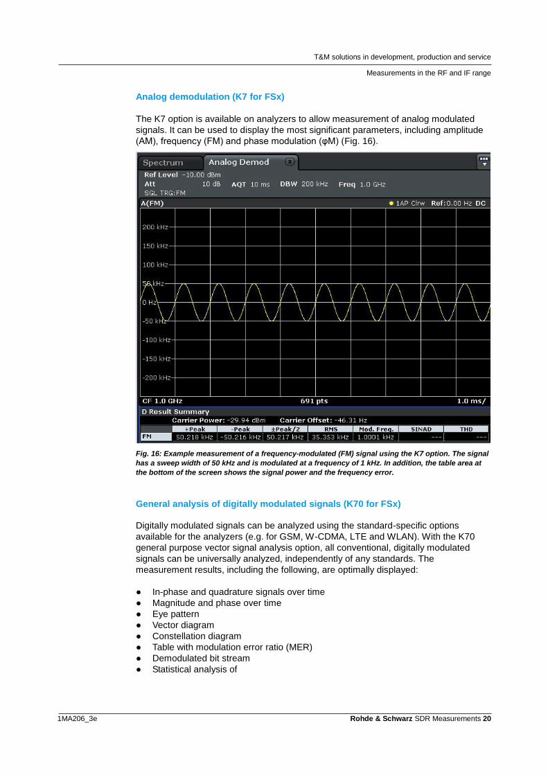
Analog demodulation (K7 for FSx)
The K7 option is available on analyzers to allow measurement of analog modulated
signals. It can be used to display the most significant parameters, including amplitude
(AM), frequency (FM) and phase modulation (φM) (Fig. 16).
Fig. 16: Example measurement of a frequency-modulated (FM) signal using the K7 option. The signal
has a sweep width of 50 kHz and is modulated at a frequency of 1 kHz. In addition, the table area at
the bottom of the screen shows the signal power and the frequency error.
General analysis of digitally modulated signals (K70 for FSx)
Digitally modulated signals can be analyzed using the standard-specific options
available for the analyzers (e.g. for GSM, W-CDMA, LTE and WLAN). With the K70
general purpose vector signal analysis option, all conventional, digitally modulated
signals can be universally analyzed, independently of any standards. The
measurement results, including the following, are optimally displayed:
● In-phase and quadrature signals over time
● Magnitude and phase over time
● Eye pattern
● Vector diagram
● Constellation diagram
● Table with modulation error ratio (MER)
● Demodulated bit stream
● Statistical analysis of
T&M solutions in development, production and service
Measurements in the RF and IF range
1MA206_3e Rohde & Schwarz SDR Measurements 21
● Modulation parameters
● Spectral analysis
● Amplifier distortion measurements
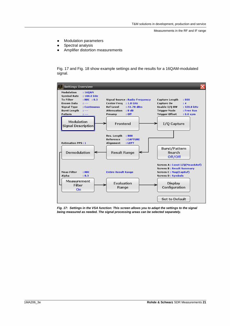
Fig. 17 and Fig. 18 show example settings and the results for a 16QAM-modulated
signal.
Fig. 17: Settings in the VSA function: This screen allows you to adapt the settings to the signal
being measured as needed. The signal processing areas can be selected separately.
T&M solutions in development, production and service
Measurements in the RF and IF range
1MA206_3e Rohde & Schwarz SDR Measurements 22
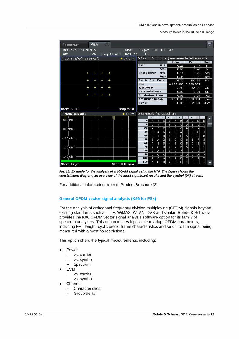
Fig. 18: Example for the analysis of a 16QAM signal using the K70. The figure shows the
constellation diagram, an overview of the most significant results and the symbol (bit) stream.
For additional information, refer to Product Brochure [2]. General OFDM vector signal analysis (K96 for FSx) For the analysis of orthogonal frequency division multiplexing (OFDM) signals beyond existing standards such as LTE, WiMAX, WLAN, DVB and similar, Rohde & Schwarz provides the K96 OFDM vector signal analysis software option for its family of spectrum analyzers. This option makes it possible to adapt OFDM parameters, including FFT length, cyclic prefix, frame characteristics and so on, to the signal being measured with almost no restrictions. This option offers the typical measurements, including:
● Power
– vs. carrier
– vs. symbol
– Spectrum
● EVM
– vs. carrier
– vs. symbol
● Channel
– Characteristics
– Group delay
T&M solutions in development, production and service
Measurements in the RF and IF range
1MA206_3e Rohde & Schwarz SDR Measurements 23
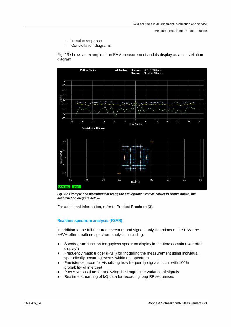
– Impulse response
– Constellation diagrams
Fig. 19 shows an example of an EVM measurement and its display as a constellation
diagram.
Fig. 19: Example of a measurement using the K96 option: EVM via carrier is shown above; the
constellation diagram below.
For additional information, refer to Product Brochure [3].
Realtime spectrum analysis (FSVR)
In addition to the full-featured spectrum and signal analysis options of the FSV, the
FSVR offers realtime spectrum analysis, including:
● Spectrogram function for gapless spectrum display in the time domain (“waterfall
display”)
● Frequency mask trigger (FMT) for triggering the measurement using individual,
sporadically occurring events within the spectrum
● Persistence mode for visualizing how frequently signals occur with 100%
probability of intercept
● Power versus time for analyzing the length/time variance of signals
● Realtime streaming of I/Q data for recording long RF sequences
T&M solutions in development, production and service
Measurements in the RF and IF range
1MA206_3e Rohde & Schwarz SDR Measurements 24
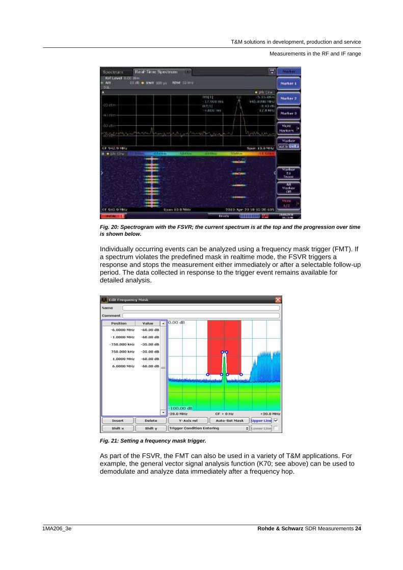
Fig. 20: Spectrogram with the FSVR; the current spectrum is at the top and the progression over time
is shown below.
Individually occurring events can be analyzed using a frequency mask trigger (FMT). If a spectrum violates the predefined mask in realtime mode, the FSVR triggers a response and stops the measurement either immediately or after a selectable follow-up period. The data collected in response to the trigger event remains available for detailed analysis.
Fig. 21: Setting a frequency mask trigger.
As part of the FSVR, the FMT can also be used in a variety of T&M applications. For example, the general vector signal analysis function (K70; see above) can be used to demodulate and analyze data immediately after a frequency hop.
T&M solutions in development, production and service
Measurements in the RF and IF range
1MA206_3e Rohde & Schwarz SDR Measurements 25
This means that the FSVR is capable of detecting very short-term phenomena. For example, it can be used to check frequency hopping in an SDR.
For cross-domain analysis, the FSVR’s realtime persistency display and frequency mask triggering can be combined with a mixed signal oscilloscope (MSO), such as the RTO, to detect critical timing errors that manifest as spectral aberrations. These could be from illegal software filter values, or transmission turn-on before hardware settling has occurred.
For additional information, refer to Product Brochure [9].
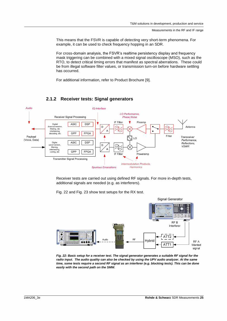
2.1.2 Receiver tests: Signal generators
Receiver tests are carried out using defined RF signals. For more in-depth tests,
additional signals are needed (e.g. as interferers).
Fig. 22 and Fig. 23 show test setups for the RX test.
Fig. 22: Basic setup for a receiver test. The signal generator generates a suitable RF signal for the
radio input. The audio quality can also be checked by using the UPV audio analyzer. At the same
time, some tests require a second RF signal as an interferer (e.g. blocking tests). This can be done
easily with the second path on the SMW.
T&M solutions in development, production and service
Measurements in the RF and IF range
1MA206_3e Rohde & Schwarz SDR Measurements 26
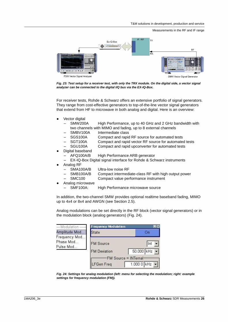
Fig. 23: Test setup for a receiver test, with only the TRX module. On the digital side, a vector signal
analyzer can be connected to the digital I/Q bus via the EX-IQ-Box.
For receiver tests, Rohde & Schwarz offers an extensive portfolio of signal generators.
They range from cost-effective generators to top-of-the-line vector signal generators
that extend from HF to microwave in both analog and digital. Here is an overview:
● Vector digital
– SMW200A High Performance, up to 40 GHz and 2 GHz bandwidth with
two channels with MIMO and fading, up to 8 external channels
– SMBV100A Intermediate class
– SGS100A Compact and rapid RF source for automated tests
– SGT100A Compact and rapid vector RF source for automated tests
– SGU100A Compact and rapid upconverter for automated tests
● Digital baseband
– AFQ100A/B High Performance ARB generator
– EX-IQ-Box Digital signal interface for Rohde & Schwarz instruments
● Analog RF
– SMA100A/B Ultra-low noise RF
– SMB100A/B Compact intermediate-class RF with high output power
– SMC100 Compact value performance instrument
● Analog microwave
– SMF100A: High Performance microwave source
In addition, the two-channel SMW provides optional realtime baseband fading, MIMO
up to 4x4 or 8x4 and AWGN (see Section 2.5).
Analog modulations can be set directly in the RF block (vector signal generators) or in
the modulation block (analog generators) (Fig. 24).
Fig. 24: Settings for analog modulation (left: menu for selecting the modulation; right: example
settings for frequency modulation (FM)).
T&M solutions in development, production and service
Measurements in the RF and IF range
1MA206_3e Rohde & Schwarz SDR Measurements 27
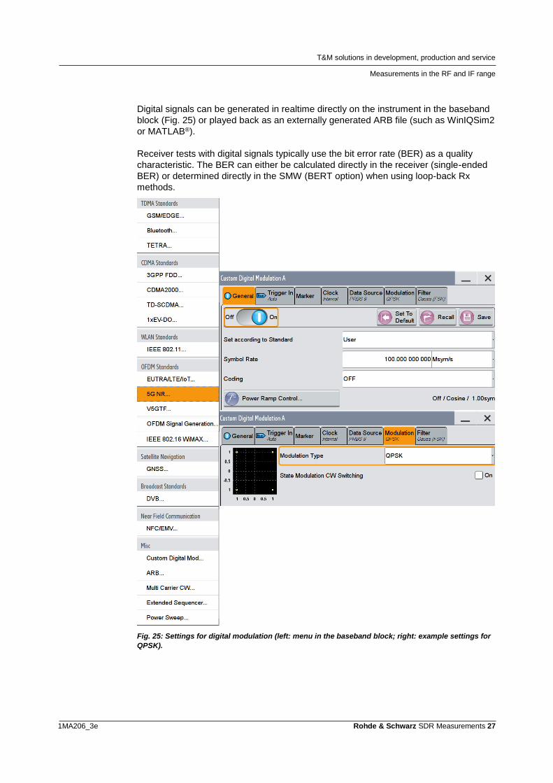
Digital signals can be generated in realtime directly on the instrument in the baseband
block (Fig. 25) or played back as an externally generated ARB file (such as WinIQSim2
or MATLAB®).
Receiver tests with digital signals typically use the bit error rate (BER) as a quality
characteristic. The BER can either be calculated directly in the receiver (single-ended
BER) or determined directly in the SMW (BERT option) when using loop-back Rx
methods.
Fig. 25: Settings for digital modulation (left: menu in the baseband block; right: example settings for
QPSK).
T&M solutions in development, production and service
Measurements in the RF and IF range
1MA206_3e Rohde & Schwarz SDR Measurements 28
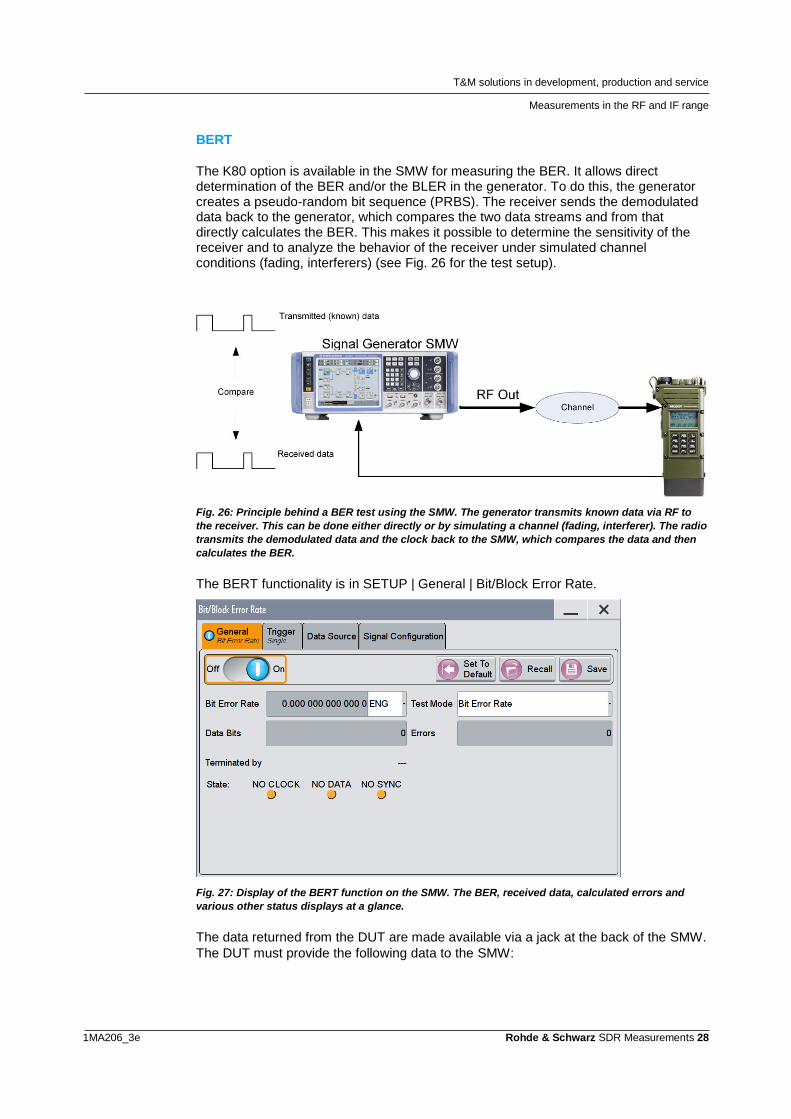
BERT
The K80 option is available in the SMW for measuring the BER. It allows direct determination of the BER and/or the BLER in the generator. To do this, the generator creates a pseudo-random bit sequence (PRBS). The receiver sends the demodulated data back to the generator, which compares the two data streams and from that directly calculates the BER. This makes it possible to determine the sensitivity of the receiver and to analyze the behavior of the receiver under simulated channel conditions (fading, interferers) (see Fig. 26 for the test setup).
Fig. 26: Principle behind a BER test using the SMW. The generator transmits known data via RF to
the receiver. This can be done either directly or by simulating a channel (fading, interferer). The radio
transmits the demodulated data and the clock back to the SMW, which compares the data and then
calculates the BER.
The BERT functionality is in SETUP | General | Bit/Block Error Rate.
Fig. 27: Display of the BERT function on the SMW. The BER, received data, calculated errors and
various other status displays at a glance.
The data returned from the DUT are made available via a jack at the back of the SMW.
The DUT must provide the following data to the SMW:
T&M solutions in development, production and service
Measurements in the RF and IF range
1MA206_3e Rohde & Schwarz SDR Measurements 29
● Demodulated data
● Clock
● Data-valid signal
● Restart signal
The radios can be connected via an interface for the MIL-STD-1553, for example.
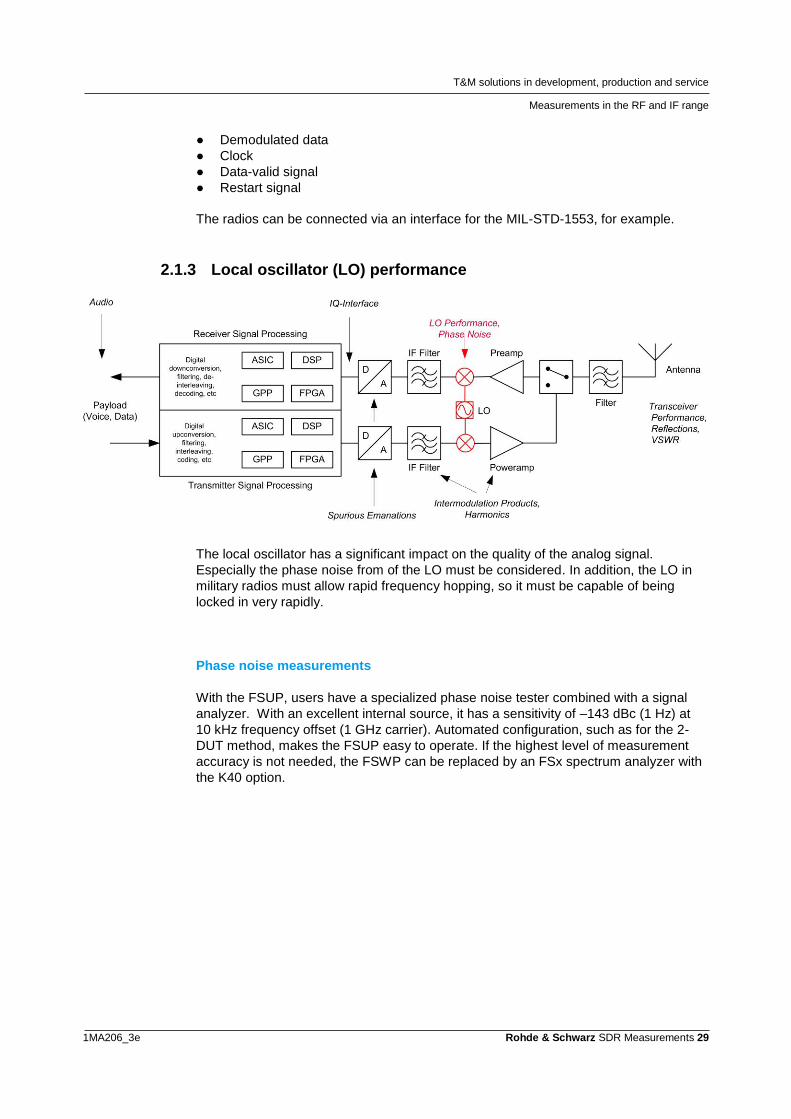
2.1.3 Local oscillator (LO) performance
The local oscillator has a significant impact on the quality of the analog signal.
Especially the phase noise from of the LO must be considered. In addition, the LO in
military radios must allow rapid frequency hopping, so it must be capable of being
locked in very rapidly.
Phase noise measurements
With the FSUP, users have a specialized phase noise tester combined with a signal
analyzer. With an excellent internal source, it has a sensitivity of –143 dBc (1 Hz) at
10 kHz frequency offset (1 GHz carrier). Automated configuration, such as for the 2-
DUT method, makes the FSUP easy to operate. If the highest level of measurement
accuracy is not needed, the FSWP can be replaced by an FSx spectrum analyzer with
the K40 option.
T&M solutions in development, production and service
Measurements in the RF and IF range
1MA206_3e Rohde & Schwarz SDR Measurements 30
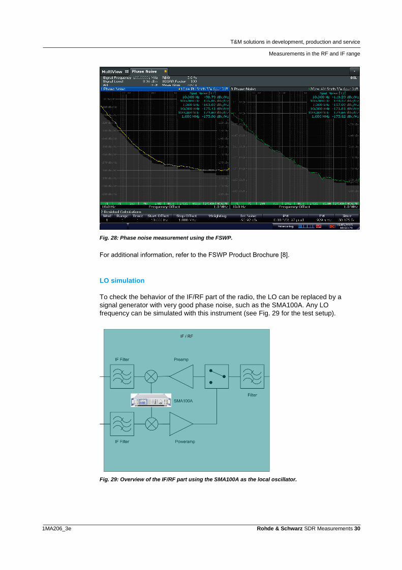
Fig. 28: Phase noise measurement using the FSWP.
For additional information, refer to the FSWP Product Brochure [8].
LO simulation
To check the behavior of the IF/RF part of the radio, the LO can be replaced by a
signal generator with very good phase noise, such as the SMA100A. Any LO
frequency can be simulated with this instrument (see Fig. 29 for the test setup).
Fig. 29: Overview of the IF/RF part using the SMA100A as the local oscillator.
T&M solutions in development, production and service
Measurements in the RF and IF range
1MA206_3e Rohde & Schwarz SDR Measurements 31
The SSB performance can be artificially degraded by using FM with noise as the
modulation. This subjects the radio to a stress test and helps to determine the design
performance margins.
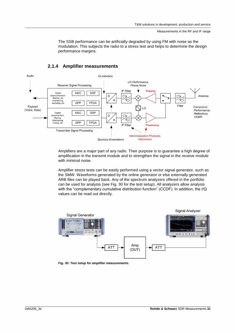
2.1.4 Amplifier measurements
Amplifiers are a major part of any radio. Their purpose is to guarantee a high degree of
amplification in the transmit module and to strengthen the signal in the receive module
with minimal noise.
Amplifier stress tests can be easily performed using a vector signal generator, such as
the SMW. Waveforms generated by the online generator or else externally generated
ARB files can be played back. Any of the spectrum analyzers offered in the portfolio
can be used for analysis (see Fig. 30 for the test setup). All analyzers allow analysis
with the “complementary cumulative distribution function” (CCDF). In addition, the I/Q
values can be read out directly.
Fig. 30: Test setup for amplifier measurements.
T&M solutions in development, production and service
Measurements in the RF and IF range
1MA206_3e Rohde & Schwarz SDR Measurements 32
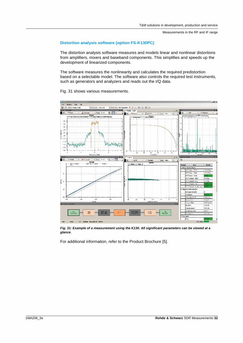
Distortion analysis software (option FS-K130PC)
The distortion analysis software measures and models linear and nonlinear distortions
from amplifiers, mixers and baseband components. This simplifies and speeds up the
development of linearized components.
The software measures the nonlinearity and calculates the required predistortion based on a selectable model. The software also controls the required test instruments, such as generators and analyzers and reads out the I/Q data.
Fig. 31 shows various measurements.
Fig. 31: Example of a measurement using the K130. All significant parameters can be viewed at a
glance.
For additional information, refer to the Product Brochure [5].
T&M solutions in development, production and service
Measurements in the RF and IF range
1MA206_3e Rohde & Schwarz SDR Measurements 33
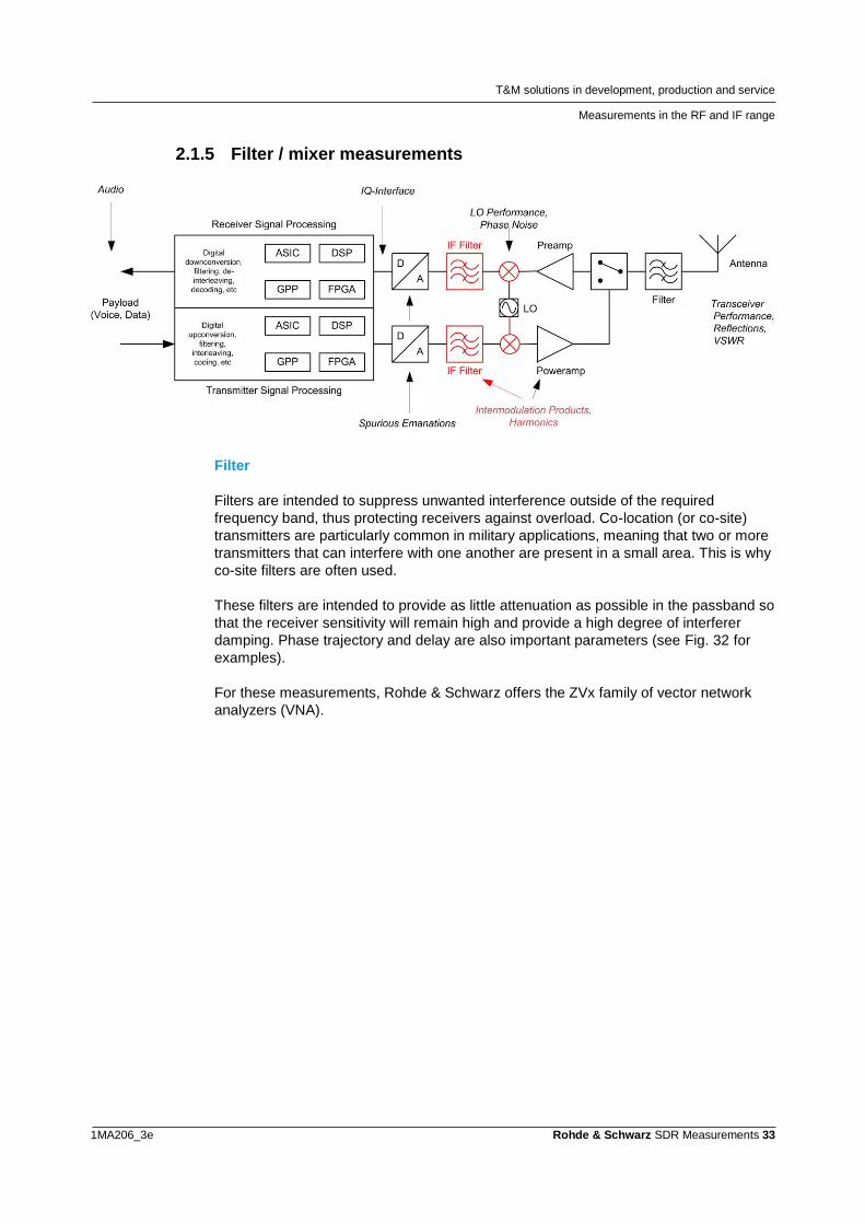
2.1.5 Filter / mixer measurements
Filter
Filters are intended to suppress unwanted interference outside of the required
frequency band, thus protecting receivers against overload. Co-location (or co-site)
transmitters are particularly common in military applications, meaning that two or more
transmitters that can interfere with one another are present in a small area. This is why
co-site filters are often used.
These filters are intended to provide as little attenuation as possible in the passband so
that the receiver sensitivity will remain high and provide a high degree of interferer
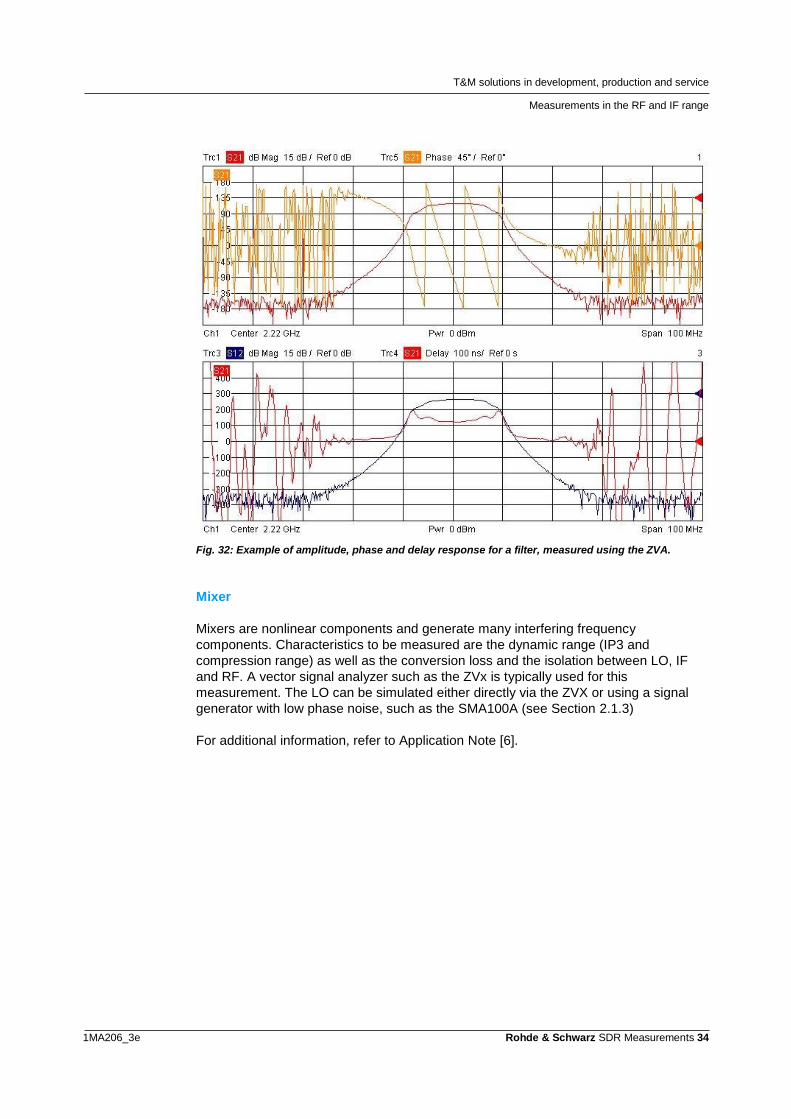
damping. Phase trajectory and delay are also important parameters (see Fig. 32 for
examples).
For these measurements, Rohde & Schwarz offers the ZVx family of vector network
analyzers (VNA).
T&M solutions in development, production and service
Measurements in the RF and IF range
1MA206_3e Rohde & Schwarz SDR Measurements 34
Fig. 32: Example of amplitude, phase and delay response for a filter, measured using the ZVA.
Mixer
Mixers are nonlinear components and generate many interfering frequency
components. Characteristics to be measured are the dynamic range (IP3 and
compression range) as well as the conversion loss and the isolation between LO, IF
and RF. A vector signal analyzer such as the ZVx is typically used for this
measurement. The LO can be simulated either directly via the ZVX or using a signal
generator with low phase noise, such as the SMA100A (see Section 2.1.3)
For additional information, refer to Application Note [6].
T&M solutions in development, production and service
Measurements in the RF and IF range
1MA206_3e Rohde & Schwarz SDR Measurements 35
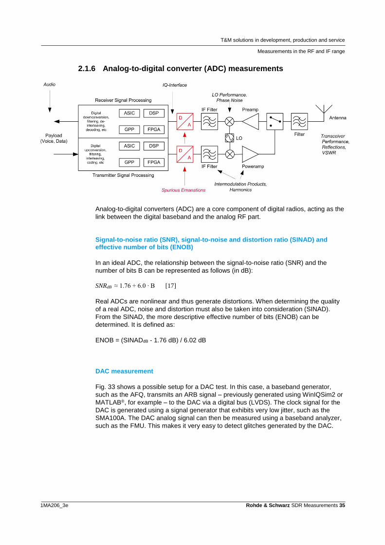
2.1.6 Analog-to-digital converter (ADC) measurements
Analog-to-digital converters (ADC) are a core component of digital radios, acting as the
link between the digital baseband and the analog RF part.
Signal-to-noise ratio (SNR), signal-to-noise and distortion ratio (SINAD) and effective number of bits (ENOB)
In an ideal ADC, the relationship between the signal-to-noise ratio (SNR) and the
number of bits B can be represented as follows (in dB):
SNRdB ≈ 1.76 + 6.0 ∙ B [17]
Real ADCs are nonlinear and thus generate distortions. When determining the quality
of a real ADC, noise and distortion must also be taken into consideration (SINAD).
From the SINAD, the more descriptive effective number of bits (ENOB) can be
determined. It is defined as:
ENOB = (SINADdB - 1.76 dB) / 6.02 dB
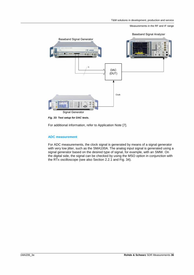
DAC measurement
Fig. 33 shows a possible setup for a DAC test. In this case, a baseband generator,
such as the AFQ, transmits an ARB signal – previously generated using WinIQSim2 or
MATLAB®, for example – to the DAC via a digital bus (LVDS). The clock signal for the
DAC is generated using a signal generator that exhibits very low jitter, such as the
SMA100A. The DAC analog signal can then be measured using a baseband analyzer,
such as the FMU. This makes it very easy to detect glitches generated by the DAC.
T&M solutions in development, production and service
Measurements in the RF and IF range
1MA206_3e Rohde & Schwarz SDR Measurements 36
Fig. 33: Test setup for DAC tests.
For additional information, refer to Application Note [7].
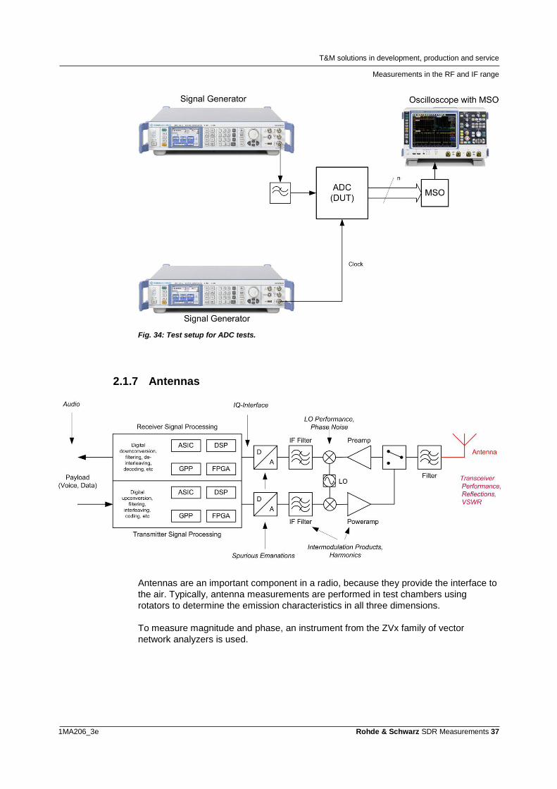
ADC measurement
For ADC measurements, the clock signal is generated by means of a signal generator with very low jitter, such as the SMA100A. The analog input signal is generated using a signal generator based on the desired type of signal, for example, with an SMW. On the digital side, the signal can be checked by using the MSO option in conjunction with the RTx oscilloscope (see also Section 2.2.1 and Fig. 34).
T&M solutions in development, production and service
Measurements in the RF and IF range
1MA206_3e Rohde & Schwarz SDR Measurements 37
Fig. 34: Test setup for ADC tests.
2.1.7 Antennas
Antennas are an important component in a radio, because they provide the interface to
the air. Typically, antenna measurements are performed in test chambers using
rotators to determine the emission characteristics in all three dimensions.
To measure magnitude and phase, an instrument from the ZVx family of vector
network analyzers is used.
T&M solutions in development, production and service
Measurements in and on the digital baseband
1MA206_3e Rohde & Schwarz SDR Measurements 38
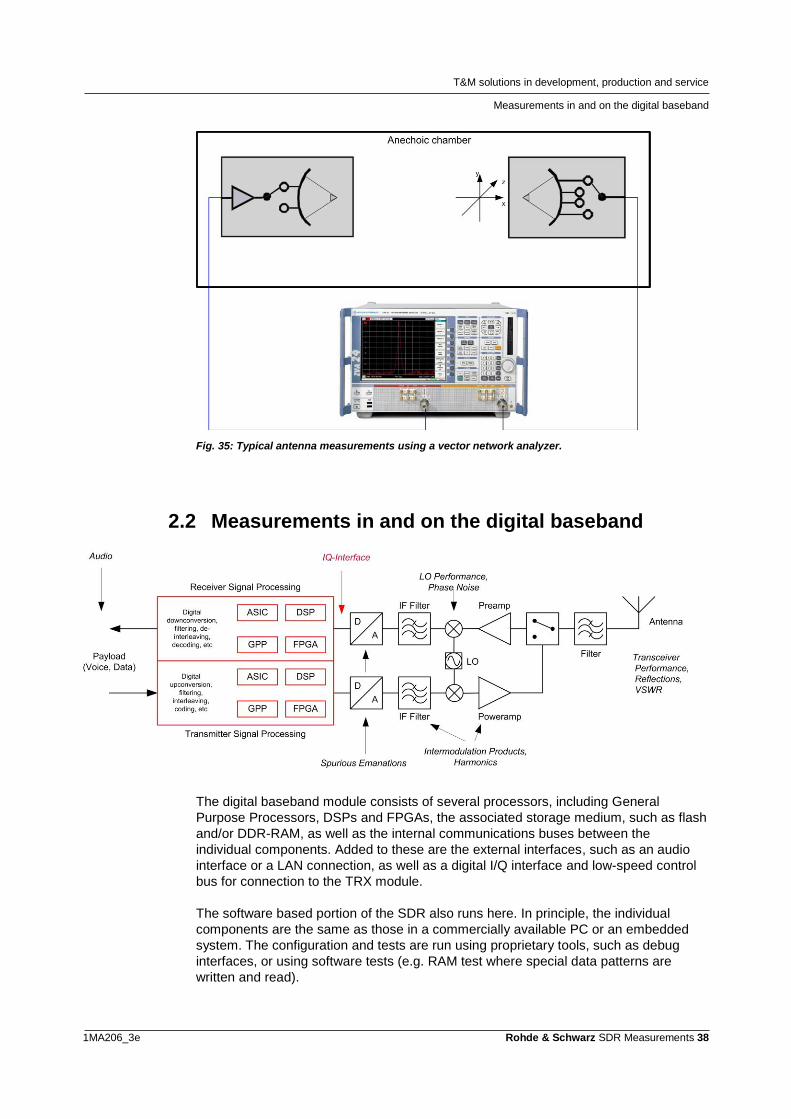
Fig. 35: Typical antenna measurements using a vector network analyzer.
2.2 Measurements in and on the digital baseband
The digital baseband module consists of several processors, including General
Purpose Processors, DSPs and FPGAs, the associated storage medium, such as flash
and/or DDR-RAM, as well as the internal communications buses between the
individual components. Added to these are the external interfaces, such as an audio
interface or a LAN connection, as well as a digital I/Q interface and low-speed control
bus for connection to the TRX module.
The software based portion of the SDR also runs here. In principle, the individual
components are the same as those in a commercially available PC or an embedded
system. The configuration and tests are run using proprietary tools, such as debug
interfaces, or using software tests (e.g. RAM test where special data patterns are
written and read).
T&M solutions in development, production and service
Measurements in and on the digital baseband
1MA206_3e Rohde & Schwarz SDR Measurements 39
Load tests are also important. They involve checking the performance of the digital
hardware under worst-case conditions. Because the waveforms that are currently
supported or planned are not sufficient, some non-standard waveforms may need to be
developed as the worst-case scenario.
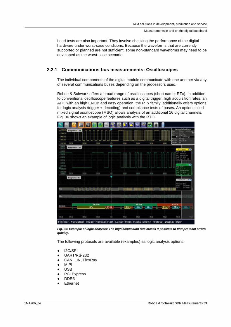
2.2.1 Communications bus measurements: Oscilloscopes
The individual components of the digital module communicate with one another via any
of several communications buses depending on the processors used.
Rohde & Schwarz offers a broad range of oscilloscopes (short name: RTx). In addition
to conventional oscilloscope features such as a digital trigger, high acquisition rates, an
ADC with an high ENOB and easy operation, the RTx family additionally offers options
for logic analysis /trigger + decoding) and compliance tests of buses. An option called
mixed signal oscilloscope (MSO) allows analysis of an additional 16 digital channels.
Fig. 36 shows an example of logic analysis with the RTO.
Fig. 36: Example of logic analysis: The high acquisition rate makes it possible to find protocol errors
quickly.
The following protocols are available (examples) as logic analysis options:
● I2C/SPI
● UART/RS-232
● CAN, LIN, FlexRay
● MIPI
● USB
● PCI Express
● DDR3
● Ethernet
T&M solutions in development, production and service
Measurements in and on the digital baseband
1MA206_3e Rohde & Schwarz SDR Measurements 40
For additional information, see our website or refer to the flyer [10].
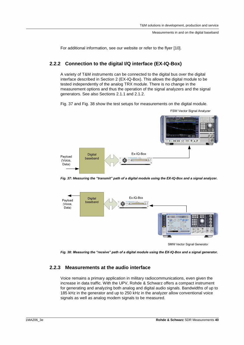
2.2.2 Connection to the digital I/Q interface (EX-IQ-Box)
A variety of T&M instruments can be connected to the digital bus over the digital
interface described in Section 2 (EX-IQ-Box). This allows the digital module to be
tested independently of the analog TRX module. There is no change in the
measurement options and thus the operation of the signal analyzers and the signal
generators. See also Sections 2.1.1 and 2.1.2.
Fig. 37 and Fig. 38 show the test setups for measurements on the digital module.
Fig. 37: Measuring the “transmit” path of a digital module using the EX-IQ-Box and a signal analyzer.
Fig. 38: Measuring the “receive” path of a digital module using the EX-IQ-Box and a signal generator.
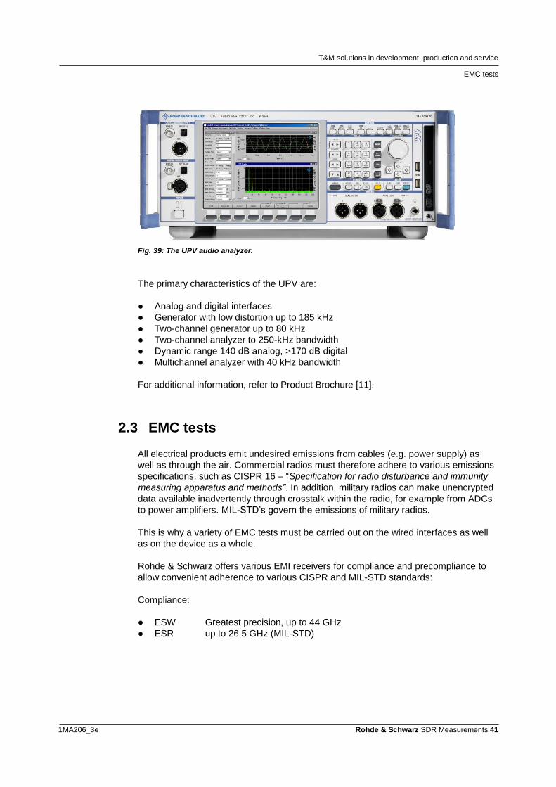
2.2.3 Measurements at the audio interface
Voice remains a primary application in military radiocommunications, even given the
increase in data traffic. With the UPV, Rohde & Schwarz offers a compact instrument
for generating and analyzing both analog and digital audio signals. Bandwidths of up to
185 kHz in the generator and up to 250 kHz in the analyzer allow conventional voice
signals as well as analog modem signals to be measured.
T&M solutions in development, production and service
EMC tests
1MA206_3e Rohde & Schwarz SDR Measurements 41
Fig. 39: The UPV audio analyzer.
The primary characteristics of the UPV are:
● Analog and digital interfaces
● Generator with low distortion up to 185 kHz
● Two-channel generator up to 80 kHz
● Two-channel analyzer to 250-kHz bandwidth
● Dynamic range 140 dB analog, >170 dB digital
● Multichannel analyzer with 40 kHz bandwidth
For additional information, refer to Product Brochure [11].
2.3 EMC tests
All electrical products emit undesired emissions from cables (e.g. power supply) as
well as through the air. Commercial radios must therefore adhere to various emissions
specifications, such as CISPR 16 – “Specification for radio disturbance and immunity
measuring apparatus and methods”. In addition, military radios can make unencrypted
data available inadvertently through crosstalk within the radio, for example from ADCs
to power amplifiers. MIL-STD’s govern the emissions of military radios.
This is why a variety of EMC tests must be carried out on the wired interfaces as well
as on the device as a whole.
Rohde & Schwarz offers various EMI receivers for compliance and precompliance to
allow convenient adherence to various CISPR and MIL-STD standards:
Compliance:
● ESW Greatest precision, up to 44 GHz
● ESR up to 26.5 GHz (MIL-STD)
T&M solutions in development, production and service
Test system for production, verification and maintenance
1MA206_3e Rohde & Schwarz SDR Measurements 42
Precompliance:
● ESRP Development and precompliance, up to 7 GHz
● ESL Compact, cost-effective precompliance solution to 6 GHz
● ESR Precompliance up to 26.5 GHZ (CISPR)
In addition, a complete, modular TS9975 test system with shielded chamber, test
antennas and EMC32 software based on the ESU is available for fully automated MIL-
STD compliant testing to 40 GHz.
For additional information, refer to Product Brochure [12].
2.4 Test system for production, verification and
maintenance
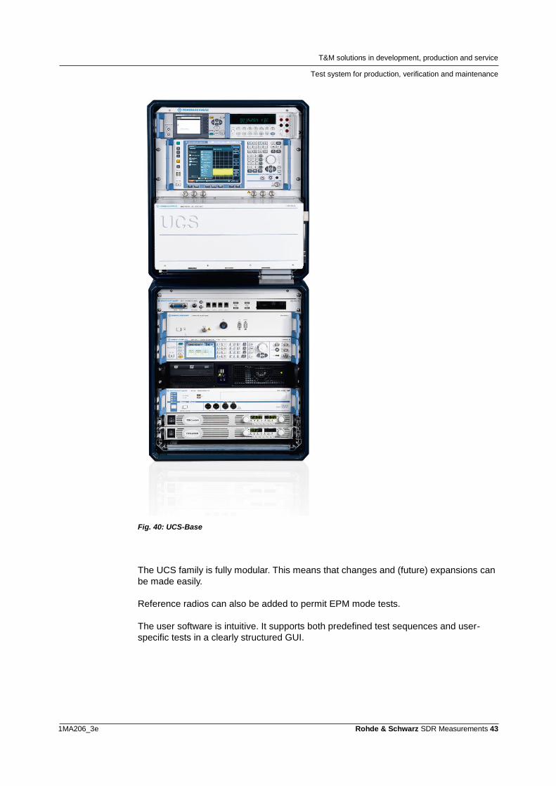
The R&S UCS Radio Test System family allows tests at different levels like production,
functional and verification testing of all Rohde & Schwarz radios (see Section 1.4). The
whole family uses the same software.
UCS-Base Radio Test Equipment:
It is suitable for on-site maintenance, repair and overhaul tests during the final
test phase. Radios can also be checked after a semi-knocked-down (SKD)
production. Finally, the system can optionally be expanded to a complete
production test system with full test depth. It is based on the UCS system,
which Rohde & Schwarz also uses for its own production of radios.
UCS-Compact Universal Radio Test Set:
Reduced scope of final tests
UCS-Compact Universal Radio Test Set:
Basic functional check
At present, the following families of radios are supported:
● SDxR
● M3xR
● Serie 4200
● Serie 2000
T&M solutions in development, production and service
Test system for production, verification and maintenance
1MA206_3e Rohde & Schwarz SDR Measurements 43
Fig. 40: UCS-Base
The UCS family is fully modular. This means that changes and (future) expansions can
be made easily.
Reference radios can also be added to permit EPM mode tests.
The user software is intuitive. It supports both predefined test sequences and user-
specific tests in a clearly structured GUI.
T&M solutions in development, production and service
Test system for production, verification and maintenance
1MA206_3e Rohde & Schwarz SDR Measurements 44
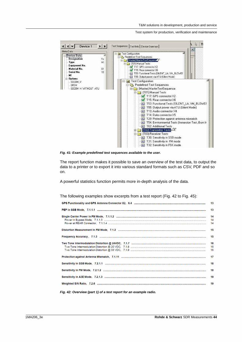
Fig. 41: Example predefined test sequences available to the user.
The report function makes it possible to save an overview of the test data, to output the
data to a printer or to export it into various standard formats such as CSV, PDF and so
on.
A powerful statistics function permits more in-depth analysis of the data.
The following examples show excerpts from a test report (Fig. 42 to Fig. 45):
Fig. 42: Overview (part 1) of a test report for an example radio.
T&M solutions in development, production and service
Test system for production, verification and maintenance
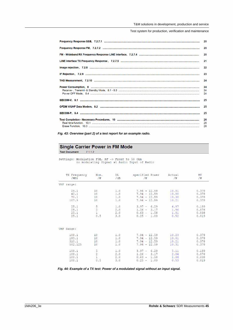
1MA206_3e Rohde & Schwarz SDR Measurements 45
Fig. 43: Overview (part 2) of a test report for an example radio.
Fig. 44: Example of a TX test: Power of a modulated signal without an input signal.
T&M solutions in development, production and service
Test system for production, verification and maintenance
1MA206_3e Rohde & Schwarz SDR Measurements 46
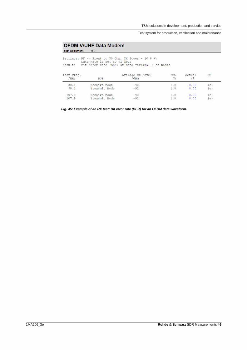
Fig. 45: Example of an RX test: Bit error rate (BER) for an OFDM data waveform.
T&M solutions in development, production and service
Channel simulator: fading
1MA206_3e Rohde & Schwarz SDR Measurements 47
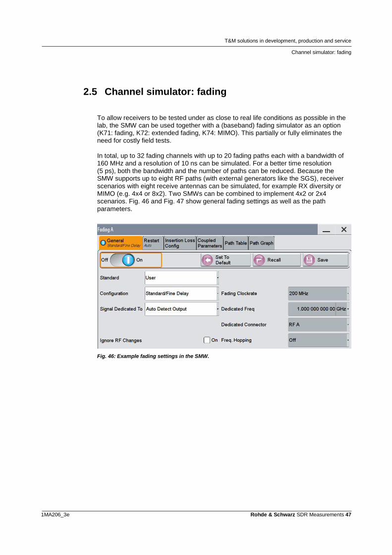
2.5 Channel simulator: fading
To allow receivers to be tested under as close to real life conditions as possible in the lab, the SMW can be used together with a (baseband) fading simulator as an option (K71: fading, K72: extended fading, K74: MIMO). This partially or fully eliminates the need for costly field tests. In total, up to 32 fading channels with up to 20 fading paths each with a bandwidth of 160 MHz and a resolution of 10 ns can be simulated. For a better time resolution (5 ps), both the bandwidth and the number of paths can be reduced. Because the SMW supports up to eight RF paths (with external generators like the SGS), receiver scenarios with eight receive antennas can be simulated, for example RX diversity or MIMO (e.g. 4x4 or 8x2). Two SMWs can be combined to implement 4x2 or 2x4 scenarios. Fig. 46 and Fig. 47 show general fading settings as well as the path parameters.
Fig. 46: Example fading settings in the SMW.
T&M solutions in development, production and service
Channel simulator: fading
1MA206_3e Rohde & Schwarz SDR Measurements 48
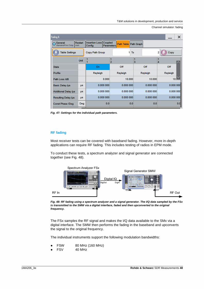
Fig. 47: Settings for the individual path parameters.
RF fading
Most receiver tests can be covered with baseband fading. However, more in-depth
applications can require RF fading. This includes testing of radios in EPM mode.
To conduct these tests, a spectrum analyzer and signal generator are connected
together (see Fig. 48).
Fig. 48: RF fading using a spectrum analyzer and a signal generator. The I/Q data sampled by the FSx
is transmitted to the SMW via a digital interface, faded and then upconverted to the original
frequency.
The FSx samples the RF signal and makes the I/Q data available to the SMx via a
digital interface. The SMW then performs the fading in the baseband and upconverts
the signal to the original frequency.
The individual instruments support the following modulation bandwidths:
● FSW 80 MHz (160 MHz)
● FSV 40 MHz
T&M solutions in development, production and service
CMA180 Radio Test Set
1MA206_3e Rohde & Schwarz SDR Measurements 49
These high modulation bandwidths also make it possible to add fading to frequency
hopping waveforms.
For additional information about RF fading, refer to Application Note 1MA145: Versatile
RF Fading Simulator [15] and the Application Card: Testing airborne radios to the limits
[18].
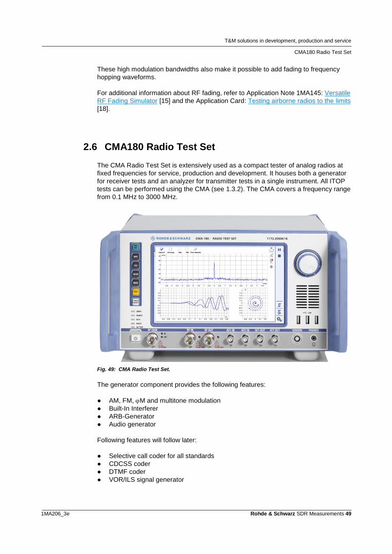
2.6 CMA180 Radio Test Set
The CMA Radio Test Set is extensively used as a compact tester of analog radios at
fixed frequencies for service, production and development. It houses both a generator
for receiver tests and an analyzer for transmitter tests in a single instrument. All ITOP
tests can be performed using the CMA (see 1.3.2). The CMA covers a frequency range
from 0.1 MHz to 3000 MHz.
Fig. 49: CMA Radio Test Set.
The generator component provides the following features:
● AM, FM, M and multitone modulation
● Built-In Interferer
● ARB-Generator
● Audio generator
Following features will follow later:
● Selective call coder for all standards
● CDCSS coder
● DTMF coder
● VOR/ILS signal generator
T&M solutions in development, production and service
CMA180 Radio Test Set
1MA206_3e Rohde & Schwarz SDR Measurements 50
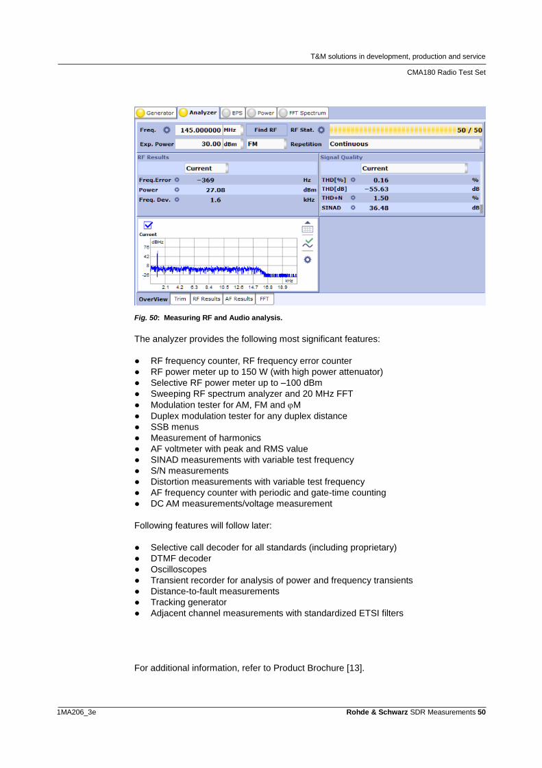
Fig. 50: Measuring RF and Audio analysis.
The analyzer provides the following most significant features:
● RF frequency counter, RF frequency error counter
● RF power meter up to 150 W (with high power attenuator)
● Selective RF power meter up to –100 dBm
● Sweeping RF spectrum analyzer and 20 MHz FFT
● Modulation tester for AM, FM and M
● Duplex modulation tester for any duplex distance
● SSB menus
● Measurement of harmonics
● AF voltmeter with peak and RMS value
● SINAD measurements with variable test frequency
● S/N measurements
● Distortion measurements with variable test frequency
● AF frequency counter with periodic and gate-time counting
● DC AM measurements/voltage measurement
Following features will follow later:
● Selective call decoder for all standards (including proprietary)
● DTMF decoder
● Oscilloscopes
● Transient recorder for analysis of power and frequency transients
● Distance-to-fault measurements
● Tracking generator
● Adjacent channel measurements with standardized ETSI filters
For additional information, refer to Product Brochure [13].
T&M solutions in development, production and service
CTH: On-site service
1MA206_3e Rohde & Schwarz SDR Measurements 51
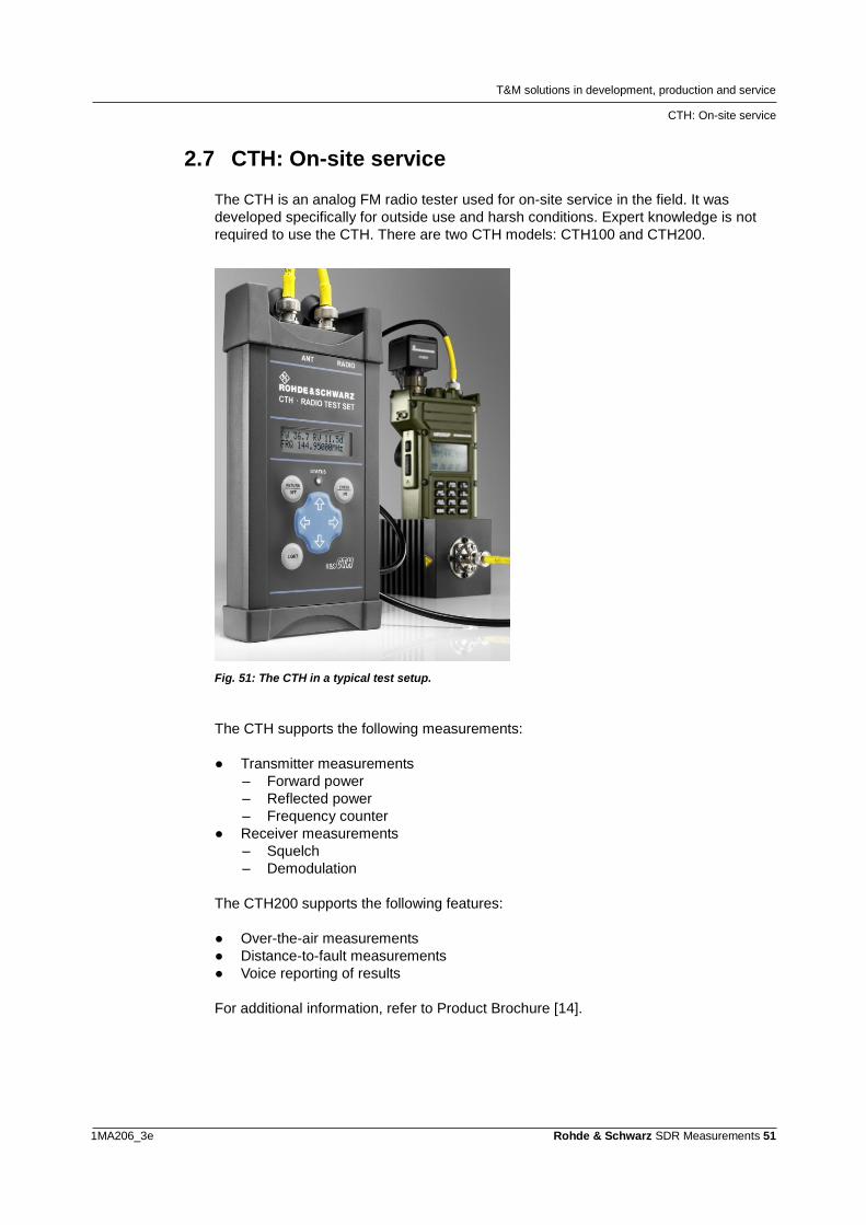
2.7 CTH: On-site service
The CTH is an analog FM radio tester used for on-site service in the field. It was
developed specifically for outside use and harsh conditions. Expert knowledge is not
required to use the CTH. There are two CTH models: CTH100 and CTH200.
Fig. 51: The CTH in a typical test setup.
The CTH supports the following measurements:
● Transmitter measurements
– Forward power
– Reflected power
– Frequency counter
● Receiver measurements
– Squelch
– Demodulation
The CTH200 supports the following features:
● Over-the-air measurements
● Distance-to-fault measurements
● Voice reporting of results
For additional information, refer to Product Brochure [14].
T&M solutions in development, production and service
Instrument integration in EDA tools
1MA206_3e Rohde & Schwarz SDR Measurements 52
2.8 Instrument integration in EDA tools
“Electronic design automation” (EDA) tools are invaluable for the design of RF/microwave systems and communications systems. In addition to the usual chip design, increasing numbers of functions are being supported that improve the target accuracy and reduce the number of design cycles, thus reducing the time to market. A variety of design and simulation tools are available on the market. To ensure that the simulations apply to many domains, Rohde & Schwarz has made it easy to integrate their T&M instruments into these tools. Rohde & Schwarz thus not only brings standard-compliant signals into the tools, but also allows instrument remote control and smooth data transfer.
Please visit our EDA software support website for more information about how to
integrate our instruments into these tools:
● MATLAB® by The MathWorks™
● Microwave Office® (MWO) and Visual System Simulator™ (VSS) from AWR
● Advanced Design System (ADS) from Agilent
Appendix
Literature
1MA206_3e Rohde & Schwarz SDR Measurements 53
3 Appendix
3.1 Literature
[1] International Test Operations Procedure (ITOP) 6-2-242: Analog
Communication Transmitter and Receiver Test Procedures, October 1993
[2] Rohde & Schwarz: NRP USB and LAN Power Sensors, Product Brochure,
October 2016
[3] Rohde & Schwarz: Signal and Spectrum Analyzers, Product Brochure,
August 2013
[4] Rohde & Schwarz: OFDM Vector Signal Analysis, Product Brochure, April
2013
[5] Rohde & Schwarz: Distortion Analysis Software, Product Brochure, March
2014
[6] Rohde & Schwarz: Performing Mixer Measurements with the Vector Network Analyzer ZVA, Application Note 1EZ58, March 2009
[7] Rohde & Schwarz: Selecting a Signal Generator for Testing AD converters, Application Note 1GP66, December 2010
[8] Rohde & Schwarz: FSWP, Product Brochure, April 2018 [9] Rohde & Schwarz: FSVR, Product Brochure, November 2010 [10] Rohde & Schwarz: Oscilloscope innovation, Flyer, März 2018
[11] Rohde & Schwarz: UPV, Product Brochure, July 2010
[12] Rohde & Schwarz: EMV, Product Brochure, March 2006 [13] Rohde & Schwarz: CMA180, Product Brochure, Juni 2016
[14] Rohde & Schwarz: CTH, Product Brochure, August 2013
[15] Rohde & Schwarz: Versatile RF Fading Simulator, Application Note 1MA145
[16] Rohde & Schwarz: Starting Successfully with the R&S®EX-IQ-Box, Application Note 1MA186, Mai 2012
[17] Rohde & Schwarz: The Effective Number of Bits (ENOB) of my R&S Digital Oscilloscope, Application Note 1ER03_1e, April 2011
[18] Rohde & Schwarz: Testing airborne radios to the limits, Application Card
Appendix
Additional information
1MA206_3e Rohde & Schwarz SDR Measurements 54
3.2 Additional information
Please send any comments or suggestions about this application note to
Visit us at
http://www.rohde-schwarz.com/
or registered users can visit the GLORIS customer website at
https://extranet.rohde-schwarz.com/
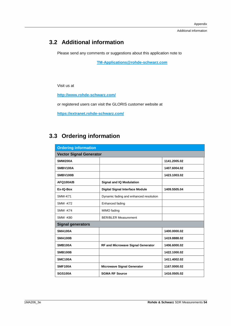
3.3 Ordering information
Ordering information
Vector Signal Generator
SMW200A 1141.2005.02
SMBV100A 1407.6004.02
SMBV100B 1423.1003.02
AFQ100A/B Signal and IQ Modulation
Ex-IQ-Box Digital Signal Interface Module 1409.5505.04
SMW-K71 Dynamic fading and enhanced resolution
SMW -K72 Enhanced fading
SMW -K74 MIMO fading
SMW -K80 BER/BLER Measurement
Signal generators
SMA100A 1400.0000.02
SMA100B 1419.8888.02
SMB100A RF and Microwave Signal Generator 1406.6000.02
SMB100B 1422.1000.02
SMC100A 1411.4002.02
SMF100A Microwave Signal Generator 1167.0000.02
SGS100A SGMA RF Source 1416.0505.02
Appendix
Ordering information
1MA206_3e Rohde & Schwarz SDR Measurements 55
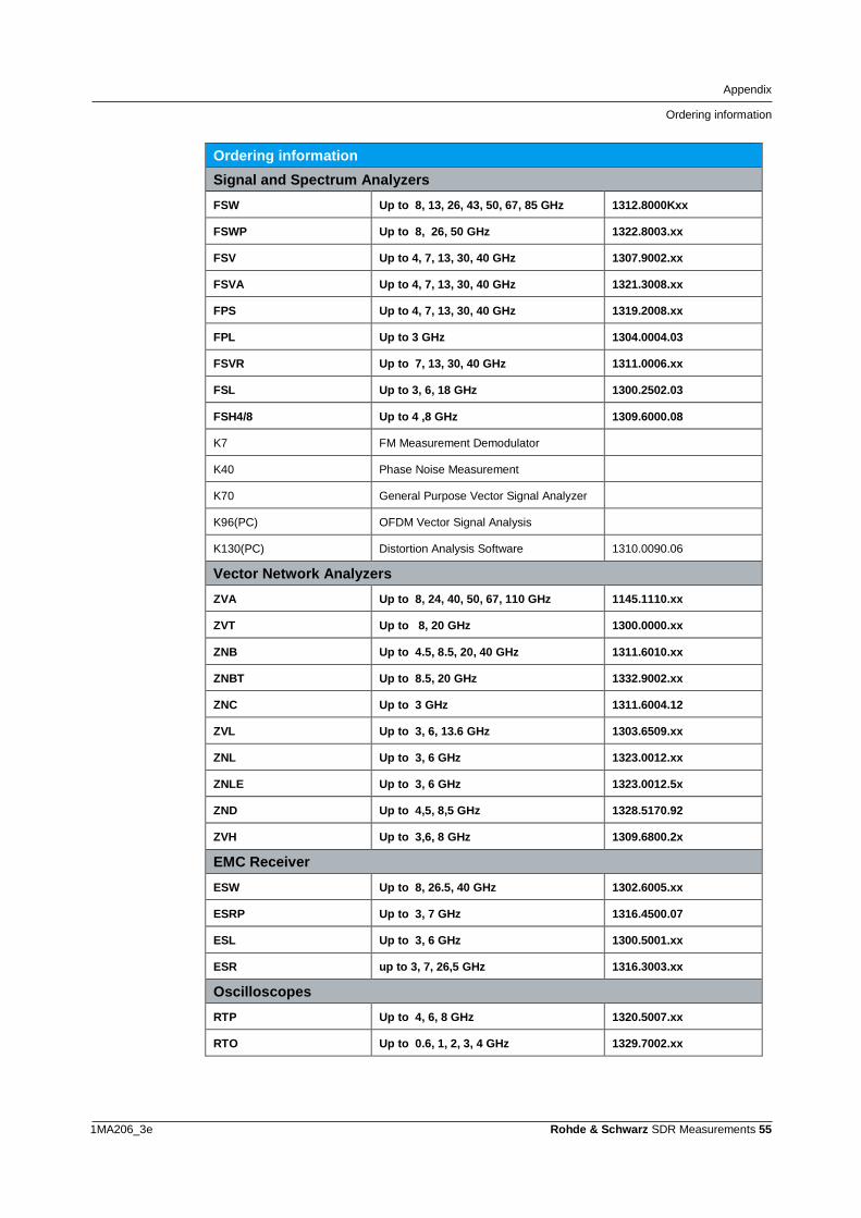
Ordering information
Signal and Spectrum Analyzers
FSW Up to 8, 13, 26, 43, 50, 67, 85 GHz 1312.8000Kxx
FSWP Up to 8, 26, 50 GHz 1322.8003.xx
FSV Up to 4, 7, 13, 30, 40 GHz 1307.9002.xx
FSVA Up to 4, 7, 13, 30, 40 GHz 1321.3008.xx
FPS Up to 4, 7, 13, 30, 40 GHz 1319.2008.xx
FPL Up to 3 GHz 1304.0004.03
FSVR Up to 7, 13, 30, 40 GHz 1311.0006.xx
FSL Up to 3, 6, 18 GHz 1300.2502.03
FSH4/8 Up to 4 ,8 GHz 1309.6000.08
K7 FM Measurement Demodulator
K40 Phase Noise Measurement
K70 General Purpose Vector Signal Analyzer
K96(PC) OFDM Vector Signal Analysis
K130(PC) Distortion Analysis Software 1310.0090.06
Vector Network Analyzers
ZVA Up to 8, 24, 40, 50, 67, 110 GHz 1145.1110.xx
ZVT Up to 8, 20 GHz 1300.0000.xx
ZNB Up to 4.5, 8.5, 20, 40 GHz 1311.6010.xx
ZNBT Up to 8.5, 20 GHz 1332.9002.xx
ZNC Up to 3 GHz 1311.6004.12
ZVL Up to 3, 6, 13.6 GHz 1303.6509.xx
ZNL Up to 3, 6 GHz 1323.0012.xx
ZNLE Up to 3, 6 GHz 1323.0012.5x
ZND Up to 4,5, 8,5 GHz 1328.5170.92
ZVH Up to 3,6, 8 GHz 1309.6800.2x
EMC Receiver
ESW Up to 8, 26.5, 40 GHz 1302.6005.xx
ESRP Up to 3, 7 GHz 1316.4500.07
ESL Up to 3, 6 GHz 1300.5001.xx
ESR up to 3, 7, 26,5 GHz 1316.3003.xx
Oscilloscopes
RTP Up to 4, 6, 8 GHz 1320.5007.xx
RTO Up to 0.6, 1, 2, 3, 4 GHz 1329.7002.xx
Appendix
Ordering information
1MA206_3e Rohde & Schwarz SDR Measurements 56
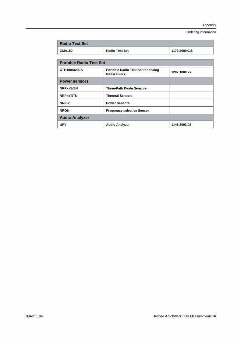
Radio Test Set
CMA180 Radio Test Set 1173.2000K18
Portable Radio Test Set
CTH100A/200A Portable Radio Test Set for analog
transceivers 1207.1000.xx
Power sensors
NRPxxS/SN Three-Path Diode Sensors
NRPxxT/TN Thermal Sensors
NRP-Z Power Sensors
NRQ6 Frequency selective Sensor
Audio Analyzer
UPV Audio Analyzer 1146.2003.02
Rohde & Schwarz The Rohde & Schwarz electronics group offers innovative solutions in the following business fields: test and measurement, broadcast and media, secure communications, cybersecurity, radiomonitoring and radiolocation. Founded more than 80 years ago, this independent company has an extensive sales and service network and is present in more than 70 countries. The electronics group is among the world market leaders in its established business fields. The company is headquartered in Munich, Germany. It also has regional headquarters in Singapore and Columbia, Maryland, USA, to manage its operations in these regions.
Regional contact Europe, Africa, Middle East +49 89 4129 12345 [email protected] North America 1 888 TEST RSA (1 888 837 87 72) [email protected] Latin America +1 410 910 79 88 [email protected] Asia Pacific +65 65 13 04 88 [email protected] China +86 800 810 82 28 |+86 400 650 58 96 [email protected] Sustainable product design ı Environmental compatibility and eco-footprint ı Energy efficiency and low emissions ı Longevity and optimized total cost of ownership
This application note and the supplied programs may only be used subject to the conditions of use set forth in the download area of the Rohde & Schwarz website.
R&S® is a registered trademark of Rohde & Schwarz GmbH & Co.
KG; Trade names are trademarks of the owners.
Rohde & Schwarz GmbH & Co. KG
Mühldorfstraße 15 | D - 81671 München
Phone + 49 89 4129 - 0 | Fax + 49 89 4129 – 13777
www.rohde-schwarz.com