Introduction to SDR Software Defined Radiowb2elw.net/SDR_Intro_by_KC2AYK.pdf · Software-defined...
36
Introduction to SDR Software Defined Radio By: Ken Pokigo, KC2AYK
Transcript of Introduction to SDR Software Defined Radiowb2elw.net/SDR_Intro_by_KC2AYK.pdf · Software-defined...

Introduction toSDR
Software Defined Radio
By:
Ken Pokigo, KC2AYK

Basic Intro to SDR:
We will limit this introduction to receiver architecture onlyWe wont talk about complex superhetordyne receivers such as double or triple conversionSimple intro, simple math, will stay away from explanations of complex numbers
Radios before SDRThe basis of SDR I/Q

Basic RF Signals:

Basic concept of FM radio:
• We can only hear less than 20 KHz, many of us not even that High• FM radio frequency (RF) band is: 88.0 MHz – 108.0 MHz• Lets take for example a favorite station at 100.7 MHz
How do we get the FM 100.7 MHz radio waves reduced down to audio that we can hear?

Generating an FM signal:
To transmit the audio frequency range over the RF airwaves we modulate the 20 KHz audio signal onto the RF carrier of 100.7 MHz
Time domain FM signal
To get the audio signal onto the carrier we modulate.

FM Signal:
Carrier FrequencyF1
F1-F2 F1+F2
100.7 MHz
The 2 sidebands contain the sound signal
Frequency domain FM signal
Looking at the FM signal across a band of frequenciessuch as seen on a spectrum analyzer
Amplitudes of frequency components….

Basic radio receiver:
Mixer
Local Oscillator
Frequency 1
Frequency 2
F1 + F2F1 - F2
F1 = 100.7 MHz
F2 = 90.0 MHzF1 - F2 = 10.7 MHzF1 + F2 = 190.7 MHz
To get the audio signal back from the carrier we must de-modulate.
Constant we apply
All that’s left is the station’s signal
10.7 MHz, (F2) is called the intermediate frequency, IF
This method has a great advantage –we can us a fixed frequency filter of 10.7 MHz
Filter
Fc=10.7 MHzBW=150KHz

Basic analog radio receiver:
Mixer
Local Oscillator
Frequency 1
Frequency 2
F1 + F2F1 - F2
F1 = 103.7 MHz
F2 = 93.0 MHzF1 - F2 = 10.7 MHz
Filter IF fixed at 10.7 MHZ
Lets say that now we wanted to listen to another station at 103.7 MHz
93.0 MHz
FMDemodulator
Audio AMP
Speaker
Fc=10.7 MHzBW=150KHz
To get the audio signal back from the carrier we must de-modulate.

We have just created the block diagram for the basic Superheterodyne receiver!
Mixer
Local Oscillator
Frequency 1
Frequency 2
F1 - F2
10.7 MHzFilter
IF fixed
93.0 MHz
FMDemodulator
Audio AMP
SpeakerFc=10.7 MHzBW=150 KHz
103.7 MHz
• Very basic version of the superheterodyne or superhet receiver. • Many are far more complicated and can have ave more than one frequency conversion.• Other areas of additional circuitry are added to provide the required levels of performance.• Basic superheterodyne concept remains the same: using of mixing the incoming signal with a locally generated
oscillation to convert the signals to a new frequency.

Items needed for the FM radio transmission and reception:
• Modulator• Mixers• Frequency generator• Filter• Demodulator
Summarizing

• Radio can be totally configured or defined by the software• RF signal is immediately converted to a digital format, and the signal is then processed totally
digitally• Advantage is that the radio can be totally reconfigured for a new application, simply by
changing the software• Common hardware platform can be used across a variety of different products, reducing costs
SDR

Benefits:
• Radio can be totally configured or defined by the software• RF signal is immediately converted to a digital format, and the signal is then processed totally digitally• Advantage is that the radio can be totally reconfigured for a new application, simply by changing the
software• Common hardware platform can be used across a variety of different products, reducing costs
SDR•Software Controlled Radio: Radio in which some or all of the physical layer functions areSoftware Controlled. In other words this type of radio only uses software to provide control of thevarious functions that are fixed within the radio.
•Software Defined Radio: Radio in which some or all of the physical layer functions are SoftwareDefined. In other words, the software is used to determine the specification of the radio and whatit does. If the software within the radio is changed, its performance and function may change.
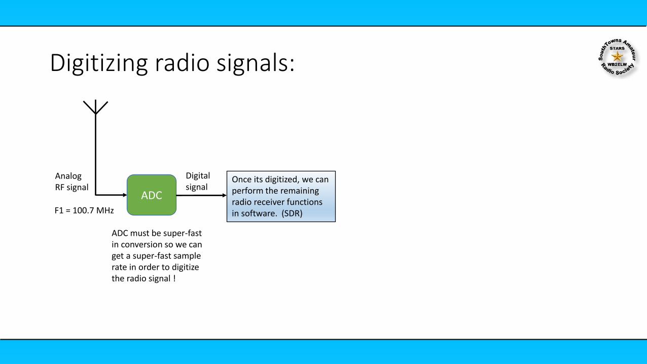
Digitizing radio signals:
ADC
Analog RF signal
F1 = 100.7 MHz
Digitalsignal
ADC must be super-fast in conversion so we can get a super-fast sample rate in order to digitize the radio signal !
Once its digitized, we can perform the remaining radio receiver functions in software. (SDR)

Digitizing radio signals:
ADC
Analog RF signal
F1 = 100.7 MHz
Digitalsignal
ADC must be super-fast in conversion so we can get a super-fast sample rate in order to digitize the radio signal !
SDR Functions
The problem is: to do A/D conversion at rates high enough to adequately sample RF, it just gets too expensive. $$$
To sample a signal properly, you must be able to sample at the Nyquist Rate.
This means that whatever amount of frequency bandwidth (BW) you’d like to capture, you must sample at a rate at least 2BW.
Sampling

Digitizing radio signals:
ADC
Analog RF signal
F1 = 2400 MHz
If we wanted to capture a WIFI signal:F1=2400 MHz
Digitalsignal
We can use a mixer to reduce the frequency
Mixer
Local Oscillator
F1 = 2389.3 MHz
F1-F2 =10.7 MHz
Much nicer and less expensive to deal with.
We would still need at least a 22 MHz sampling rate!
There has to be a better way to do this!
SDR Functions

Digitizing radio signals:
ADC
Analog RF signal
Digitalsignal
Mixer
Local Oscillator
F1-F2
Wouldn’t it be nice to get this IF down to 0 Hz?
SDR Functions
F1 = 100.7 MHzF2 = 100.7 MHz
F1 - F2 = 0 MHz

Reducing the IF:F1 = 100.7 MHzF2 = 100.7 MHz
F1 - F2 = 0 MHz
10.7 MHz 0 Hz
0 Hz
Now we only need to sample fast enough to capture our audio frequency BW of 150 KHz
150 KHz
Problem:In the Analog world these negative frequencies don’t exist!
We would actually lose ½ of the signal content.

0 Hz
The concept of using complex numbers:
i
To represent these fictious negative frequencies we create a mathematical figure called “i”, and can eliminate the negative part. (sometimes j)
i represents complex frequencies

0 Hz
The concept of using complex numbers:
i
To represent these fictious negative frequencies we create a mathematical figure called “i”, and can eliminate the negative part. (sometimes j)
i represents complex frequencies
Mathematicians can easily work with the complex numbers and create all kinds of formulas that can be represented and dealt with in software!
We can now use these concepts to allow us to work with low-cost ADCs and be able to digitize and capture without losing any signal content at all.
But how do we make deal with this in hardware so we can use the math.

Quadrature Demodulator:
Mixer
Mixer
LO
90 Phase Shift
RF
LP
Filter
LP
Filter
ADC
ADC
Q
I
I
Q
SDR interface:
• 2 signals are sampled and captured• I (horizontal)• Q (vertical)• They now represent the RF signal
This creates the I/Q signal standard for SDR (similar to mp3 for audio)
The only thing is we will need 2 ADCs in this case but they can be simple, low-cost due to the low sample rate required.

Q/I Information:
I
Q • I/Q data shows the changes in the magnitude (or amplitude) and phase of a wave.• If the amplitude and phase change in an orderly fashion, you can use these changes to encode
the information on a sine wave (or modulate it)
Sine Wave Equation
The only variables you can manipulate to encode or decode the sine wave are: • Amplitude• Frequency• Phase
What does it tell us?
Polar representation of sine wave
• Amplitude and Phase are represented
• Recurrance over time dictates the frequency
Fc of 1Hz = 2 (rad/sec)
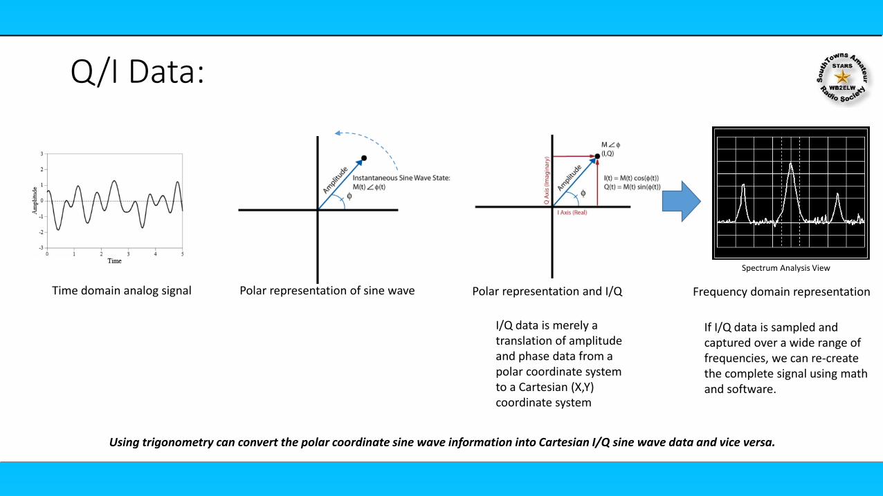
Q/I Data:
Polar representation of sine wave Polar representation and I/Q
I/Q data is merely a translation of amplitude and phase data from a polar coordinate system to a Cartesian (X,Y) coordinate system
Using trigonometry can convert the polar coordinate sine wave information into Cartesian I/Q sine wave data and vice versa.
If I/Q data is sampled and captured over a wide range of frequencies, we can re-create the complete signal using math and software.
Frequency domain representationTime domain analog signal
Spectrum Analysis View

What do we mean by SDR:
Software-defined radio (SDR) is a radio communication system where components that have been traditionally implemented in hardware (such as mixers, filters, amplifiers, modulators/demodulators, detectors, etc.) are instead implemented by means of software on computer system.
Filtering and demodulation are handled by the software.

SDR:
Mixer
Mixer
LO
90 Phase Shift
RF
LP
Filter
LP
Filter
ADC
ADC
Q
I
USB
Many SDRs will use USB as a transport to a computer.
Embedded computer or
PC
The computer runs software to do the other functions, like signal display and demodulation

SDR:If we use the quadrature demodconcept along with faster ADCs, we can capture a lot of RF spectrum bandwidth at once.
150 KHz
20 MHz
Like the entire FM broadcast band 87.8 MHz – 108.0 MHz
88.0 MHz 108.0 MHz
We would not need a superfast ADC to digitize the whole FM broadcast spectrum, and all channels at the same time!
150 KHz 150 KHz 150 KHz 150 KHz
Very low cost ($10)
10 MHz
2 MHz
Low cost ($100)
Higher cost ( $325)

RX and TX:
I
Q
• I/Q can be recorded or played back, just like with mp3 files
Storage
ReceiveRecord
I/Q
PlaybackTransmit
I/Q

The Fourier transform does the magic.
A Fast Fourier Transform or FFT is a mathematical technique for converting a signal from the time domain into the frequency domain.
• The RF signal I/Q data is captured in the time domain but can
be converted to the frequency domain.
• In the frequency domain the signal can be displayed as
frequency components.
• This is how the spectrum view is created and displayed
What do we do with this I/Q Data?
For those interested in the Math:
(We wont show you the formula, because we don’t want to loose your interest)

Frequency domain FM signalNarrowband FM has a limited modulation bandwidth.There are positive and negative frequency components.carrier as sin(ωCt)
Closer look at the frequency domain signal:

Time
Sample of broadcast RF spectrum, with visible FM station at 98.1 MHz
Digitized spectrum look from an SDR:
Frequency Spectrum View
Signal Amplitude(at each Freq)
(dBm)
Remember lower negative numbers (are actually higher in signal level.
Waterfall Display

Time
What is the “waterfall”:
The waterfall shows the frequency spectrum view over time…
View of the waterfall in a 3D format
(As viewed from above)

SDR Console Software:STARS UHF Repeater Signal
Signal Amplitude
Frequency Tuned to

TX and RXRX onlyRX only
$10-$25 $100 $300RX only
• Dual Receivers• Gigabit ethernet interface• Tuning: 70 MHz – 6 GHz• ADC: 12 bit• Sample rate: 233 Ksps – 61.4 Msps• Viewable BW: 50 MHz (per receiver)
$1000s
• 1 Receiver or Transmitter• USB interface• Tuning: 1 MHz – 6 GHz• ADC: 8 bit• Sample rate: 2 Msps – 20 Msps• Viewable BW: 20 MHz
• 1 Receiver• Integrated preselector filters• USB interface• Tuning: 1 MHz – 6 GHz• ADC: 12 bit• Sample rate: 2 Msps – 10.6 Msps• Viewable BW: 10 MHz
• 1 Receiver• USB interface• Tuning: 500 kHz – 1766 MHz• ADC: 8 bit• Sample rate: 2 Msps• Viewable BW: 2 MHz
SDR Hardware Available:
You get what you pay for!

SDR Software:
General purpose receive
• SDR Sharp• SDR Console• HDSDR• GQRX• SDRunoAll have waterfall and demodulators for all kinds if signals

SDR Software:
Special purpose
• RTL_433 – listen to sensors• DAB player – decode and listen to digital radio• RTL1090 – decode ADSB and track aircraft
Testing and Analysis• RTL_SDR – wide spectrum analyzer• RTL_Panorama– wide spectrum analyzer• Radio Hacker – hacking digital signals• IMSI-catcher - for mobile phone tracking

Ro
ute
r
SDR Receiver
Computer
USB
SDR receiver control and I/Q data capture
Stars clubhouse network
Remote SDR configuration:
SDR console Server Running
Your Home Hamshack PC
Running SDR Console remote client