
Thermal Image Sensor Application Software INSTRUCTIONS
42
Please store this manual in a designated place for future reference. INST.No.TPL-02-16 TP-L02**UN Application Software Instruction Manual CHINO Compact Thermal Image Sensor INSTRUCTION S
Transcript of Thermal Image Sensor Application Software INSTRUCTIONS
Please store this manual in a designated place for future reference.
INST.No.TPL-02-16
TP-L02**UN Application Software Instruction Manual
CHINO
Compact Thermal Image Sensor
INSTRUCTIONS
I
�Introduction Thank you for purchasing a compact thermal image sensor. In order to use this product safely, please read this instruction manual completely before use and confirm the correct handling and instructions. In addition, please retain this instruction manual for future reference.
Before using Please confirm the contents of packing. If something is missing, please contact your nearest distributor.
Names Quantity
Compact thermal image sensor 1
Custom Power/Alarm output cable 1
Custom USB cable 1
Universal head 1
Lens cap 1
Connector cap 1
Mounting screw (already mounted to the product) 1
Application software (CD)
Instruction manual (Sensor/application software) (CD) 1
Quick manual 1
About this instruction manual � Under absolutely no circumstances may the contents of this instruction manual, in part or in whole, be transcribed or copied without permission.
� The contents in this instruction manual are subject to change without notice in future. � The figures in this instruction manual may be emphasized, simplified or omitted. � Every effort has been made to ensure that the details of this manual are accurate. However, should any errors be found or important information be omitted, please inform your nearest distributor.
� The company names and brand names used in this manual are the trademarks or registered trademarks of respective companies.
About exemption from responsibility � Unless otherwise specified in the guarantee clauses, we do not offer any guarantee about this product.
� We shall not be liable to a customer or a third party for any damages or indirect damages by using this product or by unpredictable defects of the product.
Hardware requirements Compatible PC : DOS/V compatible
* .NET Framework 2.0 or later has been installed and runs correctly. * Display resolution: 800 x 600 pixels or more (recommended) OS : Windows 2000 (SP4 or later)/XP/Vista (Windows XP or later recommended)
* .NET Framework 2.0 or later (required) Communication port : LAN Hard disk : 150MB or more free space for installation Memory : Windows 2000/XP … 1GB recommended (512MB or more) : Windows Vista … 2GB or more recommended CPU : Windows 2000/XP … 1.5GHz or faster recommended
: Windows Vista … 2GHz or faster recommended � “Microsoft” and “Windows” are either trademarks or registered trademarks of Microsoft
Corporation, USA. � “Intel” and “Pentium” are either trademarks or registered trademarks of Intel Corporation, USA.
II
����Safety precautions � The safety precautions shown in this manual indicate the important contents about safety. Please be sure to understand and follow these precautions.
� In this manual, in order to use this product safely, the precautions are described with the following indications and marks.
This indicates a potentially hazardous situation that, if not avoided, will result in death or serious injury.
This indicates a potentially hazardous situation that, if not avoided, may result in minor or moderate injury or cause property damage.
[Safety precautions]
� Do not use the connecting cable other than the original use. � Do not connect the connecting cable by wet hands. It may cause an electric shock. ● Do not connect the connecting cable when the thermal image sensor or the connecting cable is
wet. It may cause an electric shock or fire by a short circuit. ● When the connecting cable is connected, be careful not to wet the thermal image sensor or the connecting cable with water, etc. It may cause an electric shock or fire by a short circuit.
● Do not place the connecting cable or the CD to a place subjected to direct sunlight or a high temperature place. In addition, do not leave them in a car of which temperature become high for a long time. It may cause discoloration, deformation or damage of them.
� Furthermore, when you connect products to be used by combining with this product, follow the instruction manual for this product. If you do not follow the instructions, we do not guarantee safety.
����Precautions for use ● Store the CD in a place not subjected to direct sunlight and protect it against dust/dirt or liquid
like water, etc. ● Handle the CD carefully. Data cannot be read if its data side and label side are scratched. ● Do not apply too much force on the connecting cable. For the connection and removal of the
cable, straight insert or pull out it by holding the connector. It may cause damage of the cable or the thermal image sensor.
● Do not wet the connecting cable by water, etc. When the cable is wet, dry it fully to use.
Warning
Caution
Warning
Caution
Ⅲ
� Contents
■ Introduction ..................................................... Ⅰ
■ Safety precautions .......................................... Ⅱ
■ Precautions for use ......................................... Ⅱ
■ Outline of product ............................................. 1 ■ Operation flowchart .......................................... 2 ■ Preparation before using .................................. 3 ■ Installation of application software ................... 4 ■Connection of thermal image sensor and PC ...... 7 ■ Installation of USB driver ............................ 8 ■ Starting application software ............................ 11 ■ Uninstall of application software ..................... 14 ■ Display of thermal images ................................ 15 ■ Screen configuration and explanation .............. 16
1. Image/Data File (F) ............................. 18 2. Sensor Setup (S)
● Alarm(Sensor) ……….............................. 19 ● Procedure for setting alarms to sensor ............ 23 ● Emissivity settings ................................... 27
3. Function (D) ● Temp Range .......................................... 28 ● Image Filter ........................................... 28 ● Rotation ........................................... 28 ● Max Temp/Min Temp ............................. 29 ● Zone Trend ............................................ 29 ● Pixel EQ .............................................. 30 ● Windows Size ...................................... 31 ● Beep [On/Off] .................................... 31 ● Zone Setup ……………….............................. 32
4. Help (H) ......................................... 37 ■ Troubleshooting ...................................... 38
1
Alarm
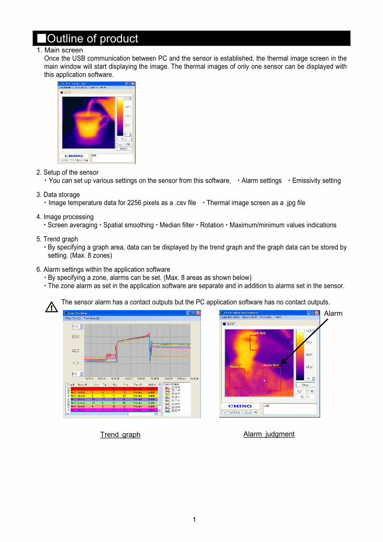
����Outline of product 1. Main screen
Once the USB communication between PC and the sensor is established, the thermal image screen in the main window will start displaying the image. The thermal images of only one sensor can be displayed with this application software.
2. Setup of the sensor
� You can set up various settings on the sensor from this software, � Alarm settings � Emissivity setting
3. Data storage � Image temperature data for 2256 pixels as a .csv file � Thermal image screen as a .jpg file
4. Image processing � Screen averaging � Spatial smoothing � Median filter � Rotation � Maximum/minimum values indications
5. Trend graph � By specifying a graph area, data can be displayed by the trend graph and the graph data can be stored by setting. (Max. 8 zones)
6. Alarm settings within the application software � By specifying a zone, alarms can be set. (Max. 8 areas as shown below) � The zone alarm as set in the application software are separate and in addition to alarms set in the sensor.
The sensor alarm has a contact outputs but the PC application software has no contact outputs.
Trend graph Alarm judgment
2
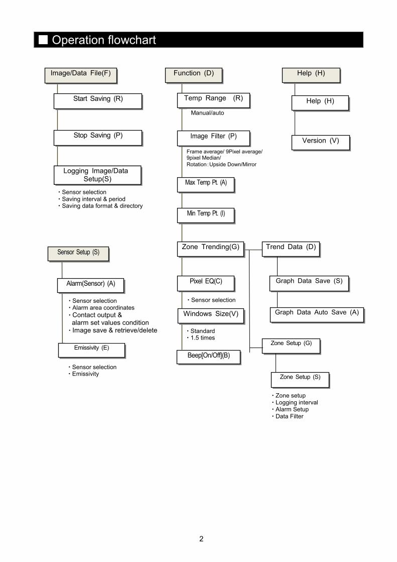
Help (H)
Version (V)
Help (H)
Function (D)
Temp Range (R)
Image Filter (P)
Max Temp Pt. (A)
Min Temp Pt. (I)
Zone Setup (G)
Zone Trending(G)
Pixel EQ(C)
Trend Data (D)
Manual/auto
Frame average/ 9Pixel average/ 9pixel Median/
Rotation:Upside Down/Mirror
� Zone setup � Logging interval � Alarm Setup � Data Filter
Sensor Setup (S)
Alarm(Sensor) (A)
Emissivity (E)
� Sensor selection � Alarm area coordinates � Contact output & alarm set values condition � Image save & retrieve/delete
Zone Setup (S)
Image/Data File(F)
Start Saving (R)
Stop Saving (P)
Logging Image/Data Setup(S)
� Sensor selection � Saving interval & period � Saving data format & directory
Windows Size(V)
� Sensor selection
� Standard � 1.5 times
Beep[On/Off](B)
���� Operation flowchart
Graph Data Save (S)
� Sensor selection � Emissivity
Graph Data Auto Save (A)
3
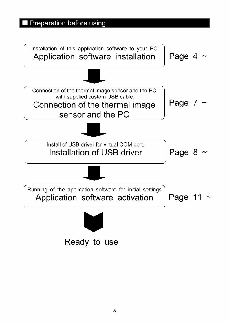
� Preparation before using
Ready to use
Page 4 ~
Page 7 ~
Page 8 ~
Page 11 ~
Installation of this application software to your PC
Application software installation
Connection of the thermal image sensor and the PC with supplied custom USB cable
Connection of the thermal image sensor and the PC
Running of the application software for initial settings
Application software activation
Install of USB driver for virtual COM port. Installation of USB driver
4
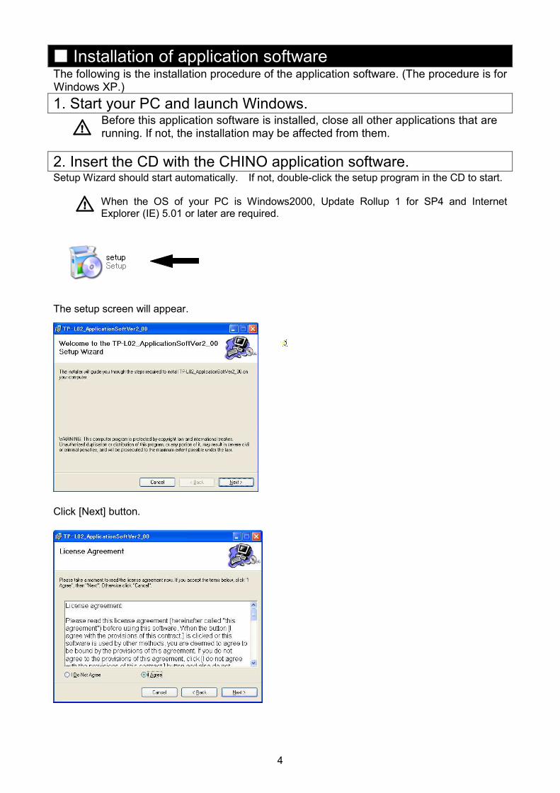
� Installation of application software The following is the installation procedure of the application software. (The procedure is for Windows XP.)
1. Start your PC and launch Windows. Before this application software is installed, close all other applications that are running. If not, the installation may be affected from them.
2. Insert the CD with the CHINO application software.
Setup Wizard should start automatically. If not, double-click the setup program in the CD to start.
When the OS of your PC is Windows2000, Update Rollup 1 for SP4 and Internet Explorer (IE) 5.01 or later are required.
The setup screen will appear. Click [Next] button.
5
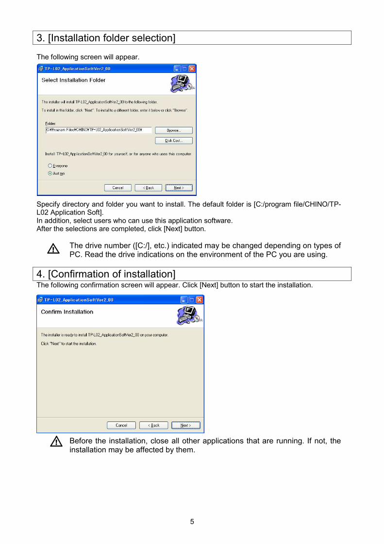
3. [Installation folder selection] The following screen will appear. Specify directory and folder you want to install. The default folder is [C:/program file/CHINO/TP-L02 Application Soft]. In addition, select users who can use this application software. After the selections are completed, click [Next] button.
The drive number ([C:/], etc.) indicated may be changed depending on types of PC. Read the drive indications on the environment of the PC you are using.
4. [Confirmation of installation] The following confirmation screen will appear. Click [Next] button to start the installation.
Before the installation, close all other applications that are running. If not, the installation may be affected by them.
6
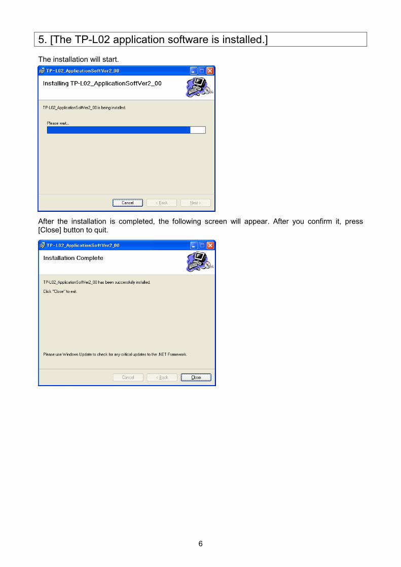
5. [The TP-L02 application software is installed.] The installation will start. After the installation is completed, the following screen will appear. After you confirm it, press [Close] button to quit.
7
[�] mark
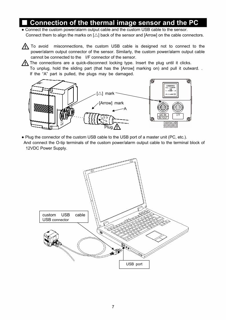
� Connection of the thermal image sensor and the PC ● Connect the custom power/alarm output cable and the custom USB cable to the sensor.
Connect them to align the marks on [�] back of the sensor and [Arrow] on the cable connectors.
To avoid misconnections, the custom USB cable is designed not to connect to the
power/alarm output connector of the sensor. Similarly, the custom power/alarm output cable
cannot be connected to the I/F connector of the sensor.
The connections are a quick-disconnect locking type. Insert the plug until it clicks.
To unplug, hold the sliding part (that has the [Arrow] marking on) and pull it outward. .
If the “A” part is pulled, the plugs may be damaged.
● Plug the connector of the custom USB cable to the USB port of a master unit (PC, etc.).
And connect the O-tip terminals of the custom power/alarm output cable to the terminal block of
12VDC Power Supply.
custom USB cable USB connector
A
USB port
[Arrow] mark
Plug
8
■Installation of USB driver The following procedure will install USB driver for virtual COM port on your PC.
Make sure the sensor is not connected to your PC before proceeding to the
following.
●Connect the custom power/alarm output cable to the sensor.
Connect them to align the marks on [�] back of the sensor and [Arrow] on the cable connectors.
●Turn the power supply of the sensor on, and connect the USB connector of custom use USB cable to your PC.
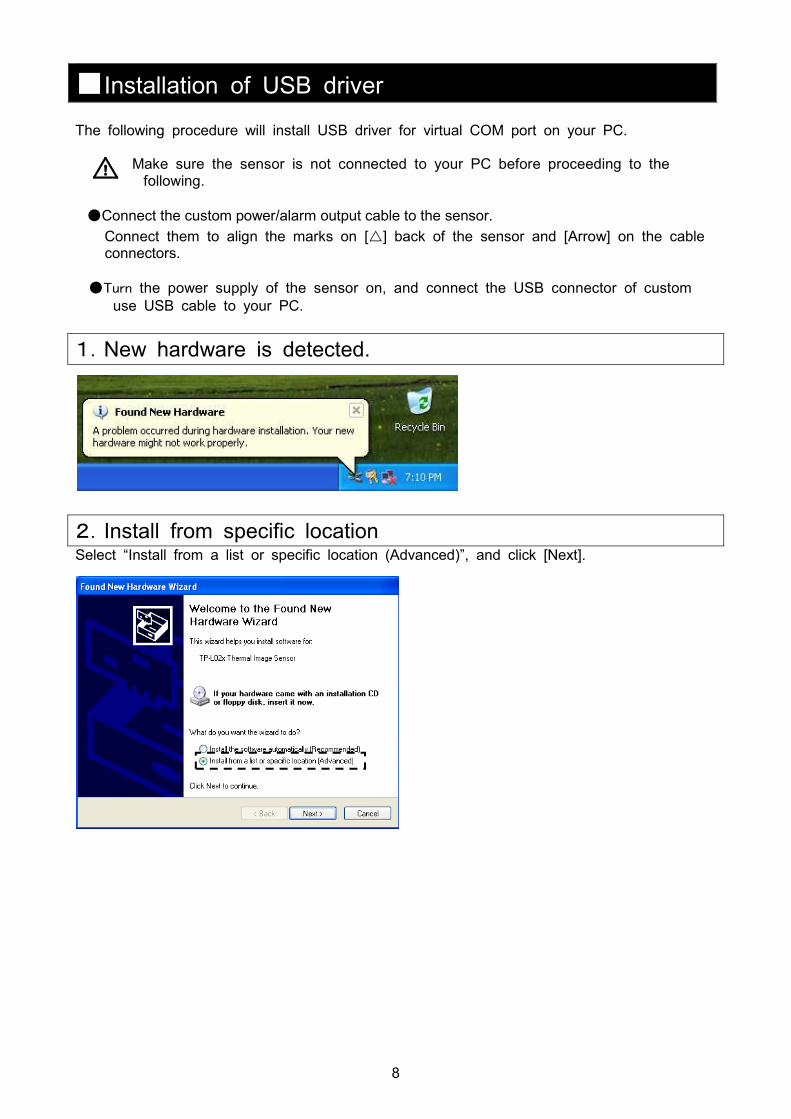
1.New hardware is detected.
2.Install from specific location Select “Install from a list or specific location (Advanced)”, and click [Next].

9
4.Insert the CD in CD-ROM. Insert the supplied CD in your CD-ROM drive.
Select “Search for the best driver in these locations”, and check “Search removable media
(floppy, CD-ROM)”, and click [Next].
5.Installation of software starts
6.Attention to the installation might be displayed. Attention to the installation might be displayed. Please click [Continue Anyway]
10
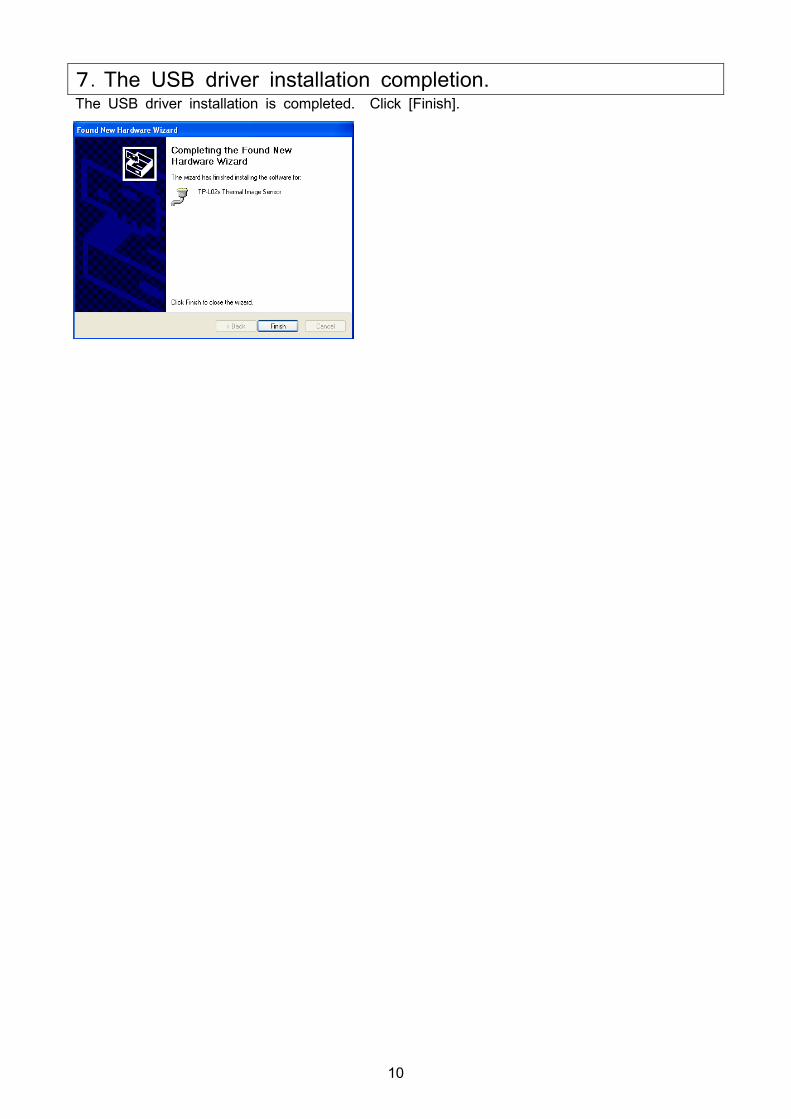
7.The USB driver installation completion. The USB driver installation is completed. Click [Finish].
11
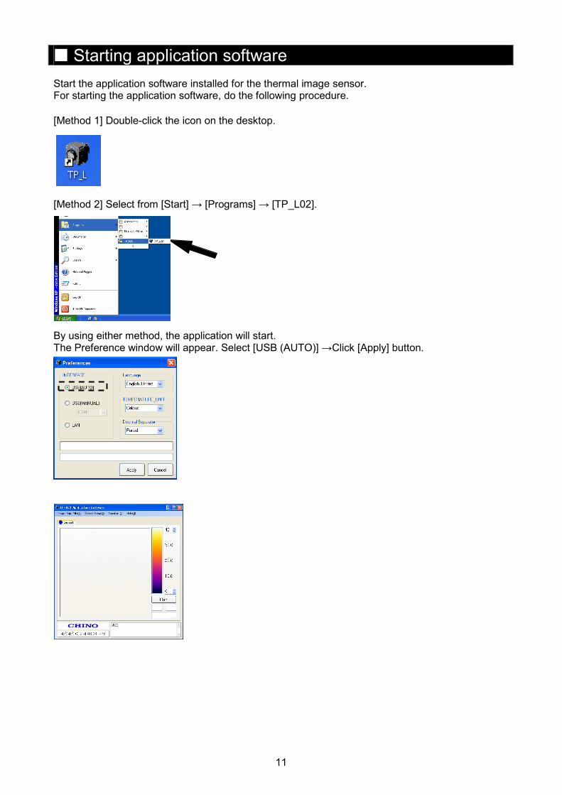
� Starting application software Start the application software installed for the thermal image sensor. For starting the application software, do the following procedure.
[Method 1] Double-click the icon on the desktop. [Method 2] Select from [Start] → [Programs] → [TP_L02]. By using either method, the application will start. The Preference window will appear. Select [USB (AUTO)] →Click [Apply] button.
12
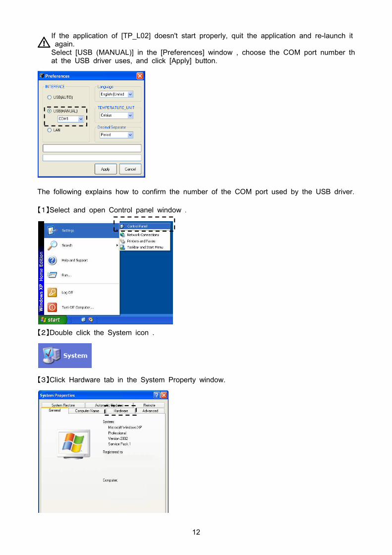
If the application of [TP_L02] doesn't start properly, quit the application and re-launch it again. Select [USB (MANUAL)] in the [Preferences] window , choose the COM port number that the USB driver uses, and click [Apply] button.
The following explains how to confirm the number of the COM port used by the USB driver.
【1】Select and open Control panel window .
【2】Double click the System icon .
【3】Click Hardware tab in the System Property window.
13
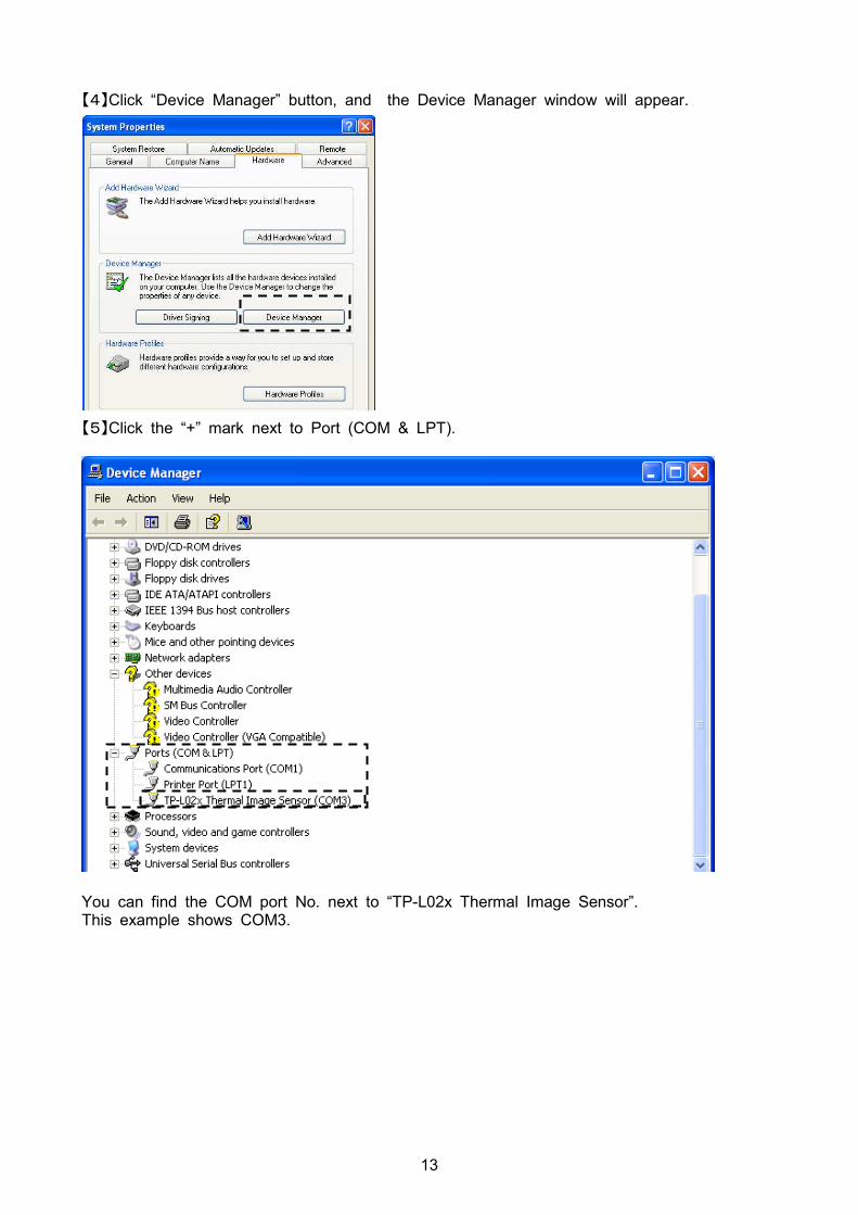
【4】Click “Device Manager” button, and the Device Manager window will appear.
【5】Click the “+” mark next to Port (COM & LPT).
You can find the COM port No. next to “TP-L02x Thermal Image Sensor”. This example shows COM3.
14
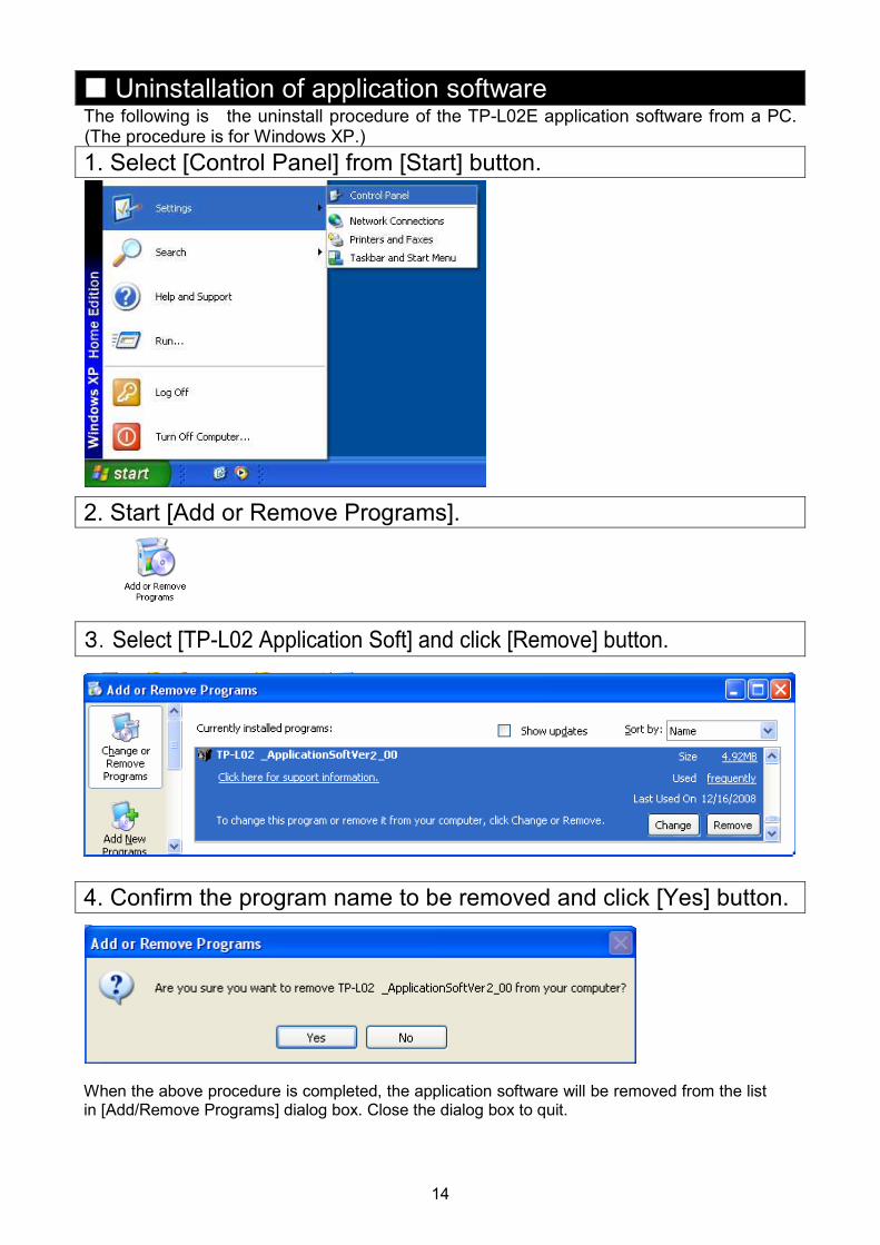
� Uninstallation of application software The following is the uninstall procedure of the TP-L02E application software from a PC. (The procedure is for Windows XP.)
1. Select [Control Panel] from [Start] button.
2. Start [Add or Remove Programs].
3.Select [TP-L02 Application Soft] and click [Remove] button.
4. Confirm the program name to be removed and click [Yes] button. When the above procedure is completed, the application software will be removed from the list in [Add/Remove Programs] dialog box. Close the dialog box to quit.
15
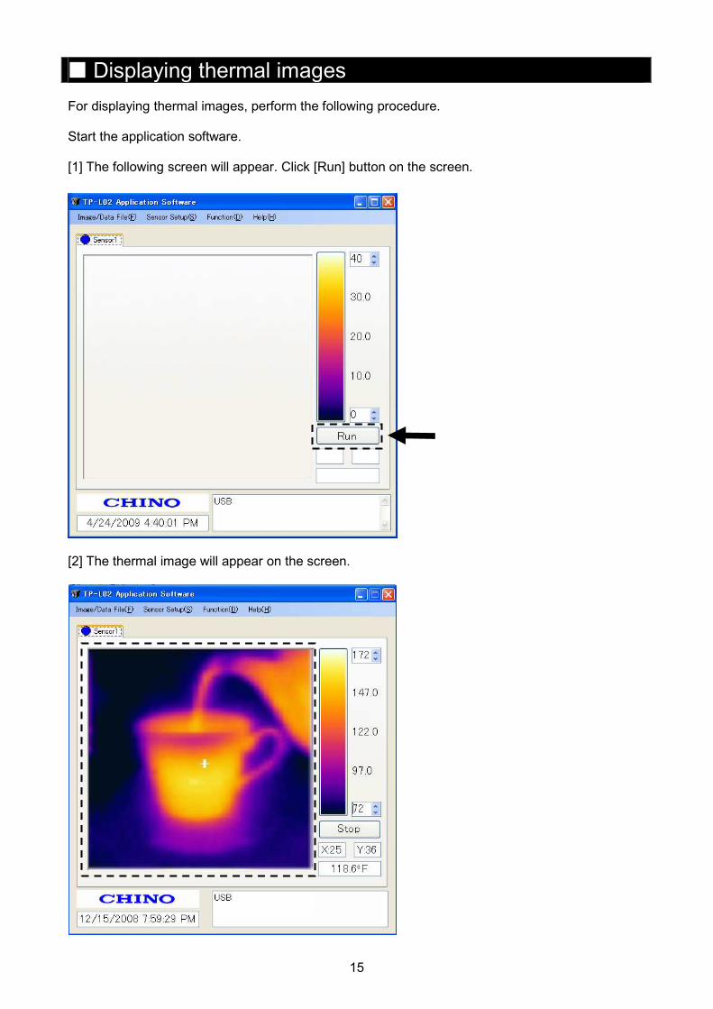
� Displaying thermal images For displaying thermal images, perform the following procedure. Start the application software.
[1] The following screen will appear. Click [Run] button on the screen.
[2] The thermal image will appear on the screen.
16
� Screen configuration and explanation
No. Names Explanations
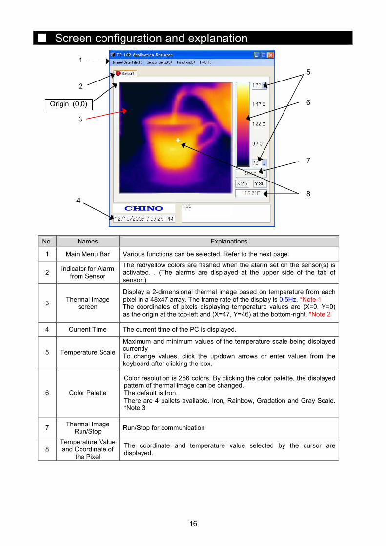
1 Main Menu Bar Various functions can be selected. Refer to the next page.
2 Indicator for Alarm
from Sensor
The red/yellow colors are flashed when the alarm set on the sensor(s) is activated. . (The alarms are displayed at the upper side of the tab of sensor.)
3 Thermal Image
screen
Display a 2-dimensional thermal image based on temperature from each pixel in a 48x47 array. The frame rate of the display is 0.5Hz. *Note 1 The coordinates of pixels displaying temperature values are (X=0, Y=0) as the origin at the top-left and (X=47, Y=46) at the bottom-right. *Note 2
4 Current Time The current time of the PC is displayed.
5 Temperature Scale
Maximum and minimum values of the temperature scale being displayed currently To change values, click the up/down arrows or enter values from the keyboard after clicking the box.
6 Color Palette
Color resolution is 256 colors. By clicking the color palette, the displayed pattern of thermal image can be changed. The default is Iron. There are 4 pallets available. Iron, Rainbow, Gradation and Gray Scale. *Note 3
7 Thermal Image
Run/Stop Run/Stop for communication
8 Temperature Value and Coordinate of
the Pixel
The coordinate and temperature value selected by the cursor are displayed.
1
2
5
3
6
7
4 8
Origin (0,0)
17
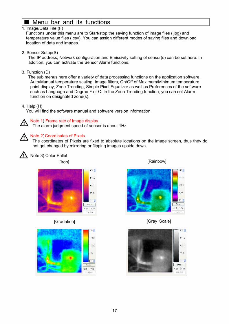
[Iron]
[Gradation] [Gray Scale]
[Rainbow]
� Menu bar and its functions 1. Image/Data File (F)
Functions under this menu are to Start/stop the saving function of image files (.jpg) and temperature value files (.csv). You can assign different modes of saving files and download location of data and images.
2. Sensor Setup(S)
The IP address, Network configuration and Emissivity setting of sensor(s) can be set here. In addition, you can activate the Sensor Alarm functions.
3. Function (D)
The sub menus here offer a variety of data processing functions on the application software. Auto/Manual temperature scaling, Image filters, On/Off of Maximum/Minimum temperature point display, Zone Trending, Simple Pixel Equalizer as well as Preferences of the software such as Language and Degree F or C. In the Zone Trending function, you can set Alarm function on designated zone(s).
4. Help (H)
You will find the software manual and software version information.
Note 1) Frame rate of Image display The alarm judgment speed of sensor is about 1Hz.
Note 2)Coordinates of Pixels The coordinates of Pixels are fixed to absolute locations on the image screen, thus they do not get changed by mirroring or flipping images upside down.
Note 3) Color Pallet
18
1. Image/Data File (F)
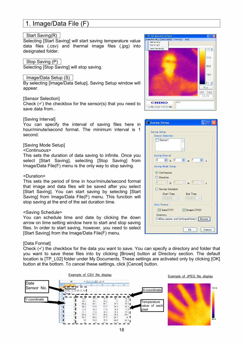
Start Saving(R) Selecting [Start Saving] will start saving temperature value data files (.csv) and thermal image files (.jpg) into designated folder.
Stop Saving (P) Selecting [Stop Saving] will stop saving.
Image/Data Setup (S) By selecting [Image/Data Setup], Saving Setup window will appear. [Sensor Selection] Check (�) the checkbox for the sensor(s) that you need to save data from.. [Saving Interval] You can specify the interval of saving files here in hour/minute/second format. The minimum interval is 1 second. [Saving Mode Setup] <Continuous> This sets the duration of data saving to infinite. Once you select [Start Saving], selecting [Stop Saving] from Image/Data File(F) menu is the only way to stop saving. <Duration> This sets the period of time in hour/minute/second format that image and data files will be saved after you select [Start Saving]. You can start saving by selecting [Start Saving] from Image/Data File(F) menu. This function will stop saving at the end of the set duration time. <Saving Schedule> You can schedule time and date by clicking the down arrow on time setting window here to start and stop saving files. In order to start saving, however, you need to select [Start Saving] from the Image/Data File(F) menu. [Data Format] Check (�) the checkbox for the data you want to save. You can specify a directory and folder that you want to save these files into by clicking [Brows] button at Directory section. The default location is [TP_L02] folder under My Documents. These settings are activated only by clicking [OK] button at the bottom. To cancel these settings, click [Cancel] button.
Example of CSV file display
Date Sensor No.
X-coordinate
Temperature value of each pixel
Y-coordinate
Example of JPEG file display
19
1 2
3
4
5
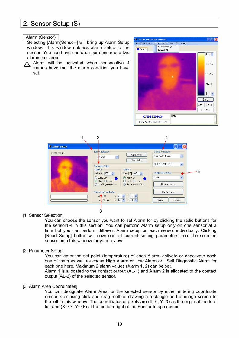
2. Sensor Setup (S) Alarm (Sensor) Selecting [Alarm(Sensor)] will bring up Alarm Setup window. This window uploads alarm setup to the sensor. You can have one area per sensor and two alarms per area.
Alarm will be activated when consecutive 4 frames have met the alarm condition you have set.
[1: Sensor Selection]
You can choose the sensor you want to set Alarm for by clicking the radio buttons for the sensor1-4 in this section. You can perform Alarm setup only on one sensor at a time but you can perform different Alarm setup on each sensor individually. Clicking [Read Setup] button will download all current setting parameters from the selected sensor onto this window for your review.
[2: Parameter Setup] You can enter the set point (temperature) of each Alarm, activate or deactivate each one of them as well as chose High Alarm or Low Alarm or Self Diagnostic Alarm for each one here. Maximum 2 alarm values (Alarm 1, 2) can be set. Alarm 1 is allocated to the contact output (AL-1) and Alarm 2 is allocated to the contact output (AL-2) of the selected sensor.
[3: Alarm Area Coordinates] You can designate Alarm Area for the selected sensor by either entering coordinate numbers or using click and drag method drawing a rectangle on the image screen to the left in this window. The coordinates of pixels are (X=0, Y=0) as the origin at the top-left and (X=47, Y=46) at the bottom-right of the Sensor Image screen.

20
[4: Config.Functions] <Auto AL/IM Reset and Manual AL/IM Reset> You can choose two types of Alarm Reset method here. “Auto Reset” resets the Alarm every time the Alarm clears itself. “Manual Reset” keeps the initial Alarm state unless you click [Alarm Reset] button in Sensor Selection. <Normally-Open/Normally-Closed > Here, you can specify either Normally-Open type or Normally-Closed type for each Contact Output.
[5: Image Save Setup] This sensor can save a thermal image and temperature data on its built-in memory when Alarm condition occurs. You have three choices for this function as follows;
O None No data or thermal image will be saved under an alarm condition.
O Alarm 1 Thermal Image will be saved when Alarm 1 is activated.
O Alarm 2
Thermal Image will be saved when Alarm 2 is activated.
For the storing timing, etc., refer to [Alarm output and saving image] (Page 22).
No images will be saved when the Self Diagnostic Alarm is activated. � Reviewing Thermal Image saved in the sensor memory. To retrieve and review saved thermal image, click [Retrieve Image] button.
When there’s no image saved in the sensor memory, the error message [No Image Data Found] will appear.
Select the condition for storing thermal image from the dropdown menu.
Click this Retrieve Image button.

21
If the thermal image has been saved in the sensor memory, the application software begins downloading the image data from the sensor after clicking the [Retrieve Image button. The progress bar indicates the download status. Wait until the downloading completes. Upon completion of downloading, the thermal image will be displayed in a new window. Adjust temperature scale and/or change color scheme palette for better image resolution.
�Saving retrieved image and temperature data To save the image and temperature data that have been retrieved from the sensor, click [Save] under File(F) on this window. A temperature data file (.csv) and a thermal image file (.jpg) will be saved into a folder called “mm/dd/yyyy_Alarm” in the folder you have specified in Saving Setup window (Under Image/Data File(F) -> Image/Data Save(S)) The date (mm/dd/yyyy) on the folder name that this saving function creates is not the time of the Alarm. It is the date the folder is created during saving function.
The temperature scale and the color palette can be adjusted here. The color palette can be changed by clicking the color bar.
22
警報有警報有警報有警報有 警報無警報無警報無警報無警報状態警報状態警報状態警報状態
警報出力警報出力警報出力警報出力
警報出力警報出力警報出力警報出力
画像保存画像保存画像保存画像保存
画像保存画像保存画像保存画像保存
警報状態警報状態警報状態警報状態がががが連続連続連続連続でででで発生発生発生発生したしたしたした場合場合場合場合はははは、、、、発発発発生時生時生時生時のののの最初最初最初最初のののの画像画像画像画像をををを保存保存保存保存するするするする
画像上書画像上書画像上書画像上書きききき
警報有警報有警報有警報有
熱画像熱画像熱画像熱画像センサセンサセンサセンサのののの電源再投入電源再投入電源再投入電源再投入又又又又はははは上上上上位位位位機器機器機器機器からのからのからのからのコマンドコマンドコマンドコマンドまでまでまでまで受信受信受信受信までまでまでまで保持保持保持保持するするするする
自動復帰自動復帰自動復帰自動復帰
保持保持保持保持熱画像熱画像熱画像熱画像センサセンサセンサセンサのののの電源再投入又電源再投入又電源再投入又電源再投入又はははは
アプリケーションソフトアプリケーションソフトアプリケーションソフトアプリケーションソフトからのからのからのからの
警報解除警報解除警報解除警報解除までまでまでまで保持保持保持保持するするするする
自己保持自己保持自己保持自己保持
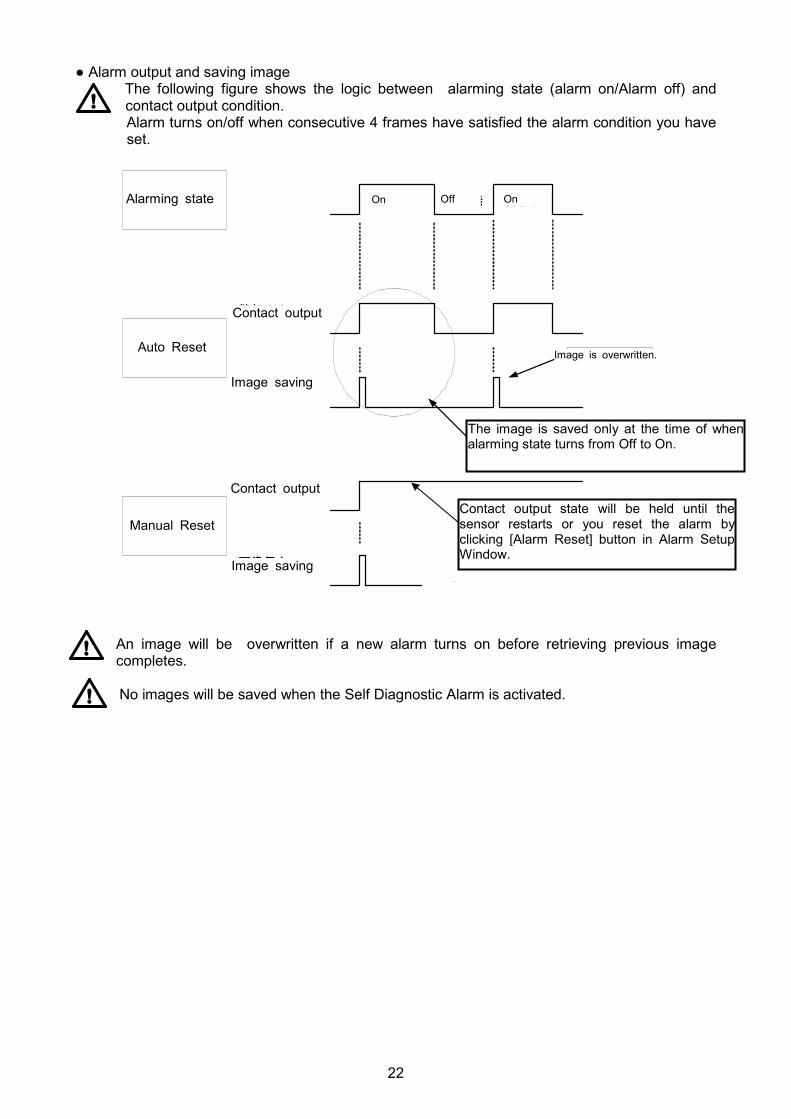
● Alarm output and saving image The following figure shows the logic between alarming state (alarm on/Alarm off) and contact output condition. Alarm turns on/off when consecutive 4 frames have satisfied the alarm condition you have set.
An image will be overwritten if a new alarm turns on before retrieving previous image completes.
No images will be saved when the Self Diagnostic Alarm is activated.
Alarming state On Off On
Auto Reset
Contact output
Image saving
Image is overwritten.
The image is saved only at the time of when alarming state turns from Off to On.
Contact output state will be held until the sensor restarts or you reset the alarm by clicking [Alarm Reset] button in Alarm Setup Window.
Manual Reset
Contact output
Image saving
23
[3]
[4]
[5]
[6]
[7]
[2] [1]
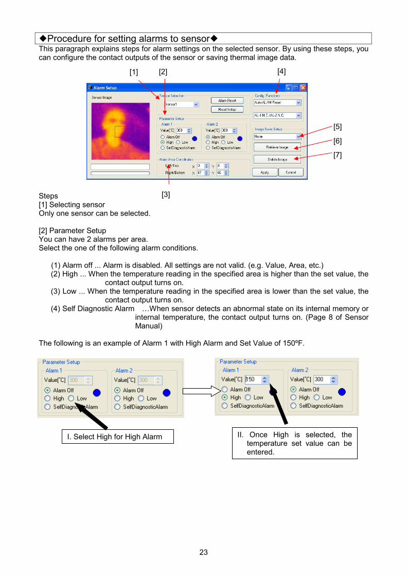
�Procedure for setting alarms to sensor� This paragraph explains steps for alarm settings on the selected sensor. By using these steps, you can configure the contact outputs of the sensor or saving thermal image data. Steps [1] Selecting sensor Only one sensor can be selected. [2] Parameter Setup You can have 2 alarms per area. Select the one of the following alarm conditions.
(1) Alarm off ... Alarm is disabled. All settings are not valid. (e.g. Value, Area, etc.) (2) High ... When the temperature reading in the specified area is higher than the set value, the
contact output turns on. (3) Low ... When the temperature reading in the specified area is lower than the set value, the
contact output turns on. (4) Self Diagnostic Alarm …When sensor detects an abnormal state on its internal memory or
internal temperature, the contact output turns on. (Page 8 of Sensor Manual)
The following is an example of Alarm 1 with High Alarm and Set Value of 150ºF.
I. Select High for High Alarm II. Once High is selected, the temperature set value can be entered.

24
[3] Designation of Alarm Area Here you can set the Alarm Area. When there is a pixel in this area that meets the conditions of the alarm settings specified by [2], the contact output signal goes out. Specify the area by using your mouse on the Sensor Image screen to the left of Alarm Setup window.
If any pixel within the alarm area meets the set value, the alarm will be triggered and provide contact outputs. Once the area is specified, the coordinate numbers of Let/Top point and Right/Bottom point are displayed in Alarm Area Coordinates section of the window. You can also perform fine adjustments of the area coordinates by changing the numbers in these boxes directly.
[4] Configuration Functions This section of the window is used to configure the type of alarm reset and alarm output configuration. There are 2 functions available.
(1) Auto Reset Alarm automatically resets when alarm condition is no longer present.
(2)Manual Reset Alarm condition will be active until the [Alarm Reset] button is clicked.
For image and data storage logic, refer to [Alarm output and saving image] (Page 22).
The following is an example of [Auto Reset].
Click your mouse at the point where you want to start the area and drag it diagonally to the point where you want to finish the area. The area will appear as a rectangular with a red line on the image screen as shown in the picture to the left.
By specifying the area, the starting point and the ending point of the area are displayed. If the fine adjustment is required, change these values.
Select the reset function from the pulldown menu.
Sensor thermal image
25
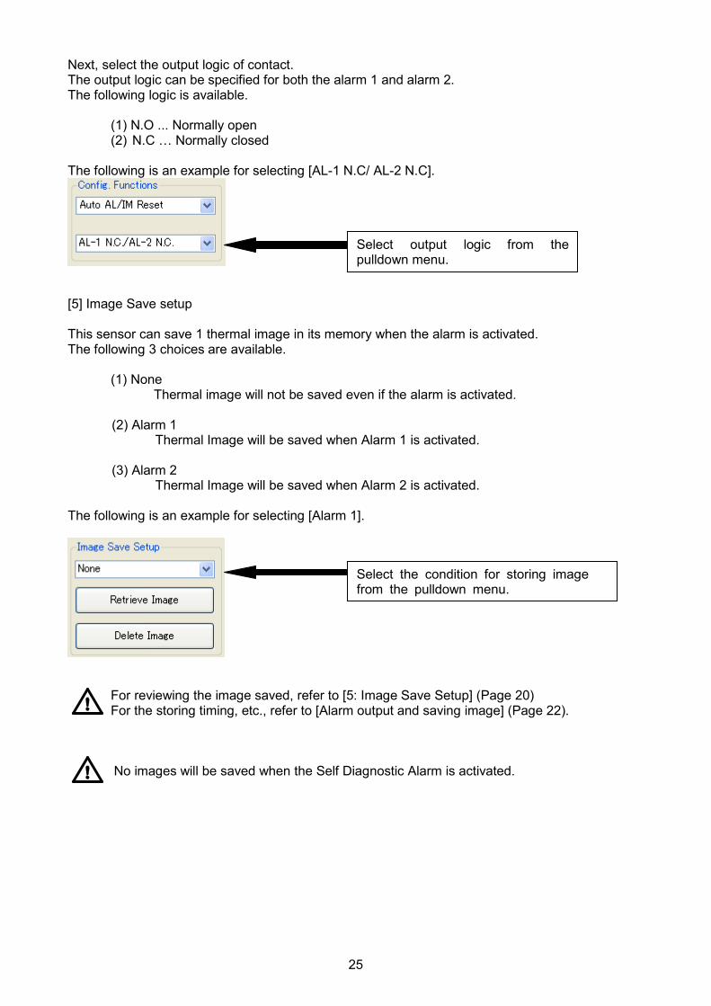
Next, select the output logic of contact. The output logic can be specified for both the alarm 1 and alarm 2. The following logic is available.
(1) N.O ... Normally open (2) N.C … Normally closed
The following is an example for selecting [AL-1 N.C/ AL-2 N.C].
[5] Image Save setup This sensor can save 1 thermal image in its memory when the alarm is activated. The following 3 choices are available.
(1) None Thermal image will not be saved even if the alarm is activated. (2) Alarm 1
Thermal Image will be saved when Alarm 1 is activated.
(3) Alarm 2 Thermal Image will be saved when Alarm 2 is activated.
The following is an example for selecting [Alarm 1].
For reviewing the image saved, refer to [5: Image Save Setup] (Page 20) For the storing timing, etc., refer to [Alarm output and saving image] (Page 22).
No images will be saved when the Self Diagnostic Alarm is activated.
Select output logic from the pulldown menu.
Select the condition for storing image from the pulldown menu.
26
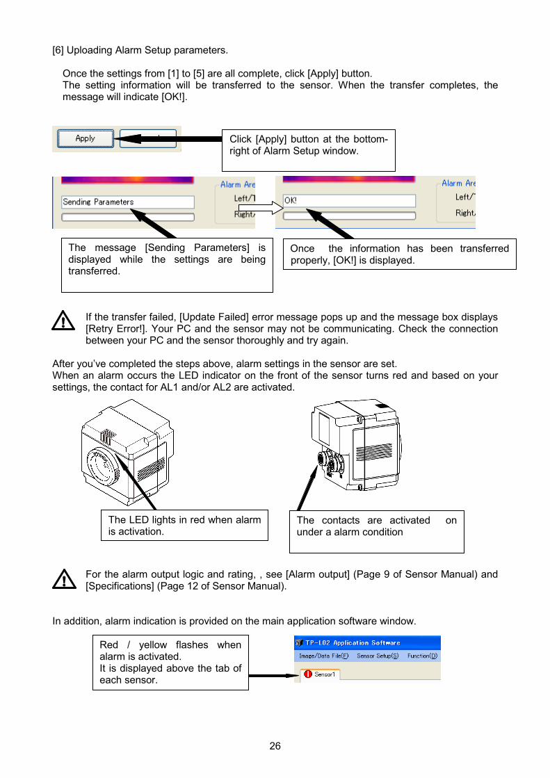
[6] Uploading Alarm Setup parameters.
Once the settings from [1] to [5] are all complete, click [Apply] button. The setting information will be transferred to the sensor. When the transfer completes, the message will indicate [OK!].
If the transfer failed, [Update Failed] error message pops up and the message box displays [Retry Error!]. Your PC and the sensor may not be communicating. Check the connection between your PC and the sensor thoroughly and try again.
After you’ve completed the steps above, alarm settings in the sensor are set. When an alarm occurs the LED indicator on the front of the sensor turns red and based on your settings, the contact for AL1 and/or AL2 are activated.
For the alarm output logic and rating, , see [Alarm output] (Page 9 of Sensor Manual) and [Specifications] (Page 12 of Sensor Manual).
In addition, alarm indication is provided on the main application software window.
Click [Apply] button at the bottom-right of Alarm Setup window.
The message [Sending Parameters] is displayed while the settings are being transferred.
Once the information has been transferred properly, [OK!] is displayed.
The LED lights in red when alarm is activation.
The contacts are activated on under a alarm condition
Red / yellow flashes when alarm is activated. It is displayed above the tab of each sensor.
27
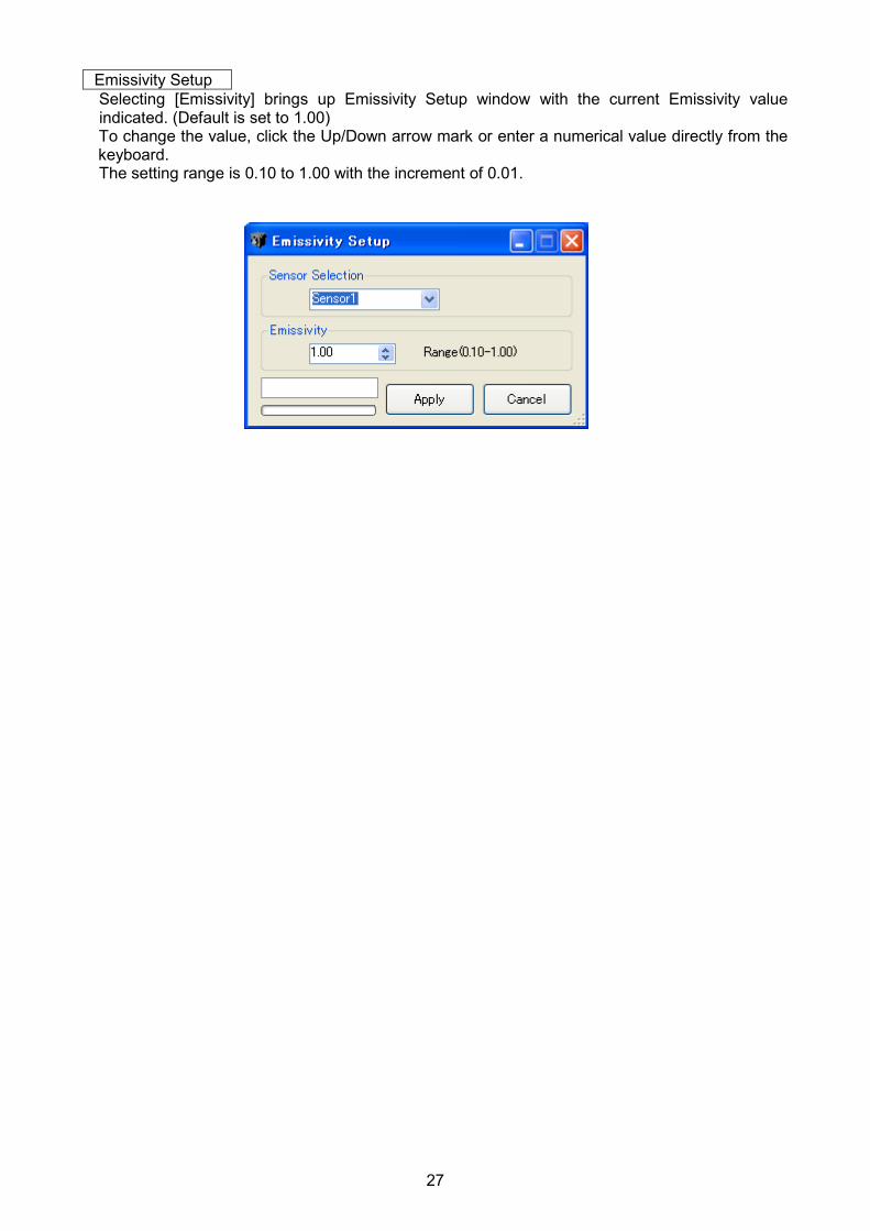
Emissivity Setup Selecting [Emissivity] brings up Emissivity Setup window with the current Emissivity value indicated. (Default is set to 1.00) To change the value, click the Up/Down arrow mark or enter a numerical value directly from the keyboard. The setting range is 0.10 to 1.00 with the increment of 0.01.
28
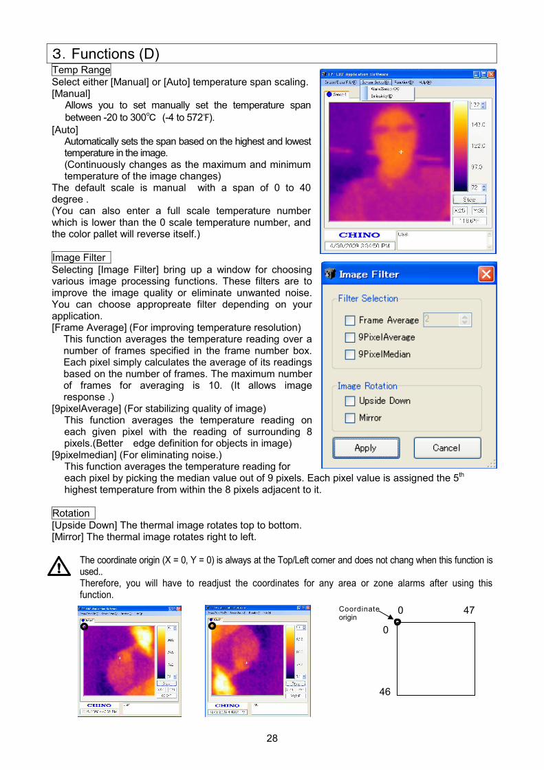
3.Functions (D) Temp Range
Select either [Manual] or [Auto] temperature span scaling. [Manual]
Allows you to set manually set the temperature span
between -20 to 300℃ (-4 to 572℉). [Auto]
Automatically sets the span based on the highest and lowest temperature in the image. (Continuously changes as the maximum and minimum temperature of the image changes)
The default scale is manual with a span of 0 to 40 degree . (You can also enter a full scale temperature number which is lower than the 0 scale temperature number, and the color pallet will reverse itself.)
Image Filter
Selecting [Image Filter] bring up a window for choosing various image processing functions. These filters are to improve the image quality or eliminate unwanted noise. You can choose appropreate filter depending on your application. [Frame Average] (For improving temperature resolution)
This function averages the temperature reading over a number of frames specified in the frame number box. Each pixel simply calculates the average of its readings based on the number of frames. The maximum number of frames for averaging is 10. (It allows image response .)
[9pixelAverage] (For stabilizing quality of image) This function averages the temperature reading on each given pixel with the reading of surrounding 8 pixels.(Better edge definition for objects in image)
[9pixelmedian] (For eliminating noise.) This function averages the temperature reading for each pixel by picking the median value out of 9 pixels. Each pixel value is assigned the 5th highest temperature from within the 8 pixels adjacent to it.
Rotation
[Upside Down] The thermal image rotates top to bottom. [Mirror] The thermal image rotates right to left.
The coordinate origin (X = 0, Y = 0) is always at the Top/Left corner and does not chang when this function is used.. Therefore, you will have to readjust the coordinates for any area or zone alarms after using this function.
Coordinate origin
0 47
0
46
29
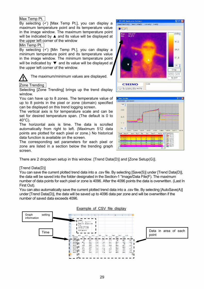
Max Temp Pt.
By selecting (�) [Max Temp Pt.], you can display a maximum temperature point and its temperature value in the image window. The maximum temperature point will be indicated by ▲ and its value will be displayed at the upper left corner of the window
Min Temp Pt.
By selecting (�) [Min Temp Pt.], you can display a minimum temperature point and its temperature value in the image window. The minimum temperature point
will be indicated by ▼ and its value will be displayed at
the upper left corner of the window.
The maximum/minimum values are displayed.
Zone Trending
Selecting [Zone Trending] brings up the trend display window. You can have up to 8 zones. The temperature value of up to 8 points in the pixel or zone (domain) specified can be displayed on this trend logging screen. The vertical axis is for temperature scale and can be set for desired temperature span. (The default is 0 to 40°C). The horizontal axis is time. The data is scrolled automatically from right to left. (Maximum 512 data points are plotted for each pixel or zone.) No historical data function is available on the screen. The corresponding set parameters for each pixel or zone are listed in a section below the trending graph screen. There are 2 dropdown setup in this window. [Trend Data(D)] and [Zone Setup(G)]. [Trend Data(D)] You can save the current plotted trend data into a .csv file. By selecting [Save(S)] under [Trend Data(D)], the data will be saved into the folder designated in the Section-1 “Image/Data File(F). The maximum number of data points for each pixel or zone is 4096. After the 4096 points the data is overwritten. (Last In First Out). You can also automatically save the current plotted trend data into a .csv file. By selecting [AutoSave(A)] under [Trend Data(D)], the data will be saved up to 4096 data per zone and will be overwritten if the number of saved data exceeds 4096.
Example of CSV file display
Data in area of each point
Time
Graph setting information
30
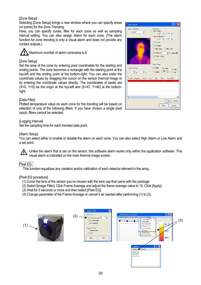
[Zone Setup] Selecting [Zone Setup] brings a new window where you can specify areas (or points) for the Zone Trending. Here, you can specify zones, filter for each zone as well as sampling interval setting. You can also assign Alarm for each zone. (The alarm function for zone trending is only a visual alarm and does not provide any contact outputs.)
Maximum number of alarm zone/area is 8.
[Zone Setup] Set the area of the zone by entering pixel coordinates for the starting and ending points. The zone becomes a rectangle with the starting point at the top-left and the ending point at the bottom-right. You can also enter the coordinate values by dragging the cursor on the sensor thermal image or by entering the coordinate values directly. The coordinates of pixels are (X=0, Y=0) as the origin at the top-left and (X=47, Y=46) at the bottom-right. [Data Filter] Plotted temperature value on each zone for the trending will be based on selection of one of the following filters. If you have chosen a single pixel (spot), filters cannot be selected. [Logging Interval] Set the sampling time for each trended data point. [Alarm Setup] You can select either to enable or disable the alarm on each zone. You can also select High Alarm or Low Alarm and a set point.
Unlike the alarm that is set on the sensor, this software alarm works only within the application software. This visual alarm is indicated on the main thermal image screen.
Pixel EQ
This function equalizes any variation and/or calibration of each detector element in the array. [Pixel EQ procedure] (1) Cover the lens of the sensor you’ve chosen with the lens cap that came with the package. (2) Select [Image Filter]. Click Frame Average and adjust the frame average value to 10. Click [Apply]. (3) Wait for 5 seconds or more and then select [Pixel EQ] (4) Change parameter of the Frame Average or cancel it as needed after performing (1) to (3).
(1)
(2) (3)
31
Windows Size(V)
The size of the screen can be changed. Select it from the given two choises (Default or 150%).
Beep[On/Off](B)
The alarm sound can be triggered on your PC when the alarm you have set in Zone Trending is activated by selecting (�)the [Beep[On/Off]] under [Function(D)] menu.
32
[1]
[2]
[3]
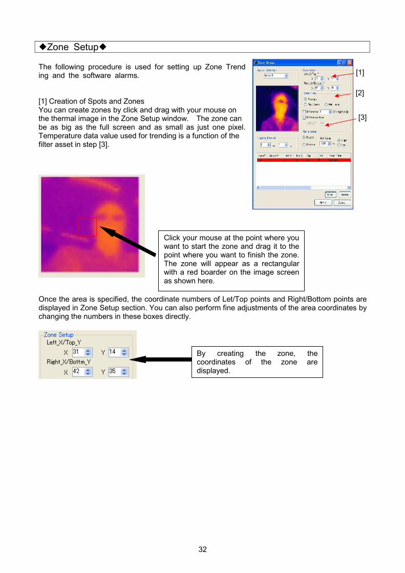
�Zone Setup� The following procedure is used for setting up Zone Trending and the software alarms. [1] Creation of Spots and Zones You can create zones by click and drag with your mouse on the thermal image in the Zone Setup window. The zone can be as big as the full screen and as small as just one pixel. Temperature data value used for trending is a function of the filter asset in step [3].
Once the area is specified, the coordinate numbers of Let/Top points and Right/Bottom points are displayed in Zone Setup section. You can also perform fine adjustments of the area coordinates by changing the numbers in these boxes directly.
Click your mouse at the point where you want to start the zone and drag it to the point where you want to finish the zone. The zone will appear as a rectangular with a red boarder on the image screen as shown here.
By creating the zone, the coordinates of the zone are displayed.

33
[2] Zone Data Filter The following choices are available;
(1) Average Calculated average value of all the data points in the zone.
(2) Max Temp Pixel with the maximum value in the zone.
(3) Min Temp Pixel with the minimum value in the zone.
(4) Difference : Time Trend the temperature difference between the current temperature and the
temperature that was taken “N” times before. (5) Difference : Area Trend the temperature difference between the zone that you are setting now and the
zone that you set in “Comparing Zone”.
If only one pixel is chosen as a zone, the zone becomes a spot. No data filter is available for a one pixel zone..
[3] Alarm Setup You can setup software alarm set in this section. You can activate the alarm by clicking the radio button of [Enable] and specify the set value for the alarm. You can also choose this alarm to be either a High Alarm or a Low Alarm as described below.
(1) High: When the temperature exceeds the set point in the zone, the zone box will flash.
(2) Low: When the temperature drops below the set point in the zone, the zone box will flash.
Make sure that you’ve registered the IP Address of the connected sensors.
Zone data filter selection
Select whether the alarm function is used or not used for selected zone.
Select the set point of the alarm in the zone.
The method of calculating the difference is selected. Zone data filter selection
34
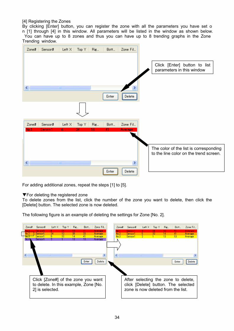
[4] Registering the Zones By clicking [Enter] button, you can register the zone with all the parameters you have set on [1] through [4] in this window. All parameters will be listed in the window as shown below. You can have up to 8 zones and thus you can have up to 8 trending graphs in the Zone Trending window.
For adding additional zones, repeat the steps [1] to [5]. �For deleting the registered zone To delete zones from the list, click the number of the zone you want to delete, then click the [Delete] button. The selected zone is now deleted. The following figure is an example of deleting the settings for Zone [No. 2].
Click [Enter] button to list parameters in this window
The color of the list is corresponding to the line color on the trend screen.
Click [Zone#] of the zone you want to delete. In this example, Zone [No. 2] is selected.
After selecting the zone to delete, click [Delete] button. The selected zone is now deleted from the list.
35
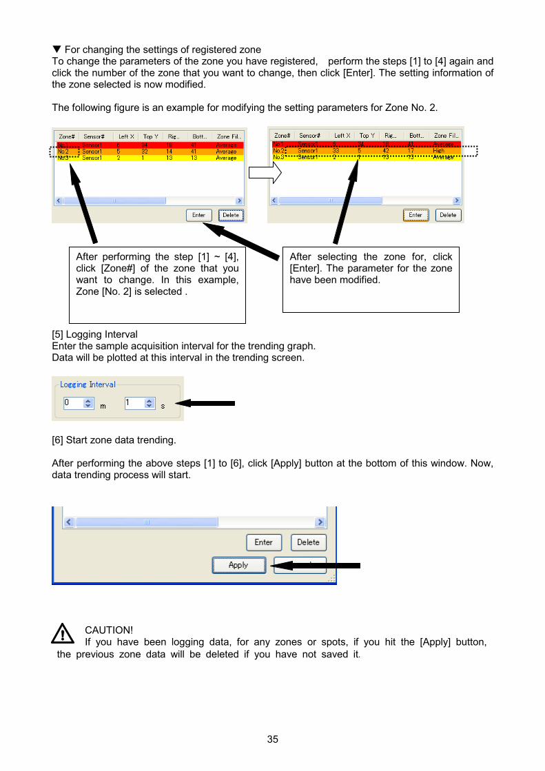
� For changing the settings of registered zone To change the parameters of the zone you have registered, perform the steps [1] to [4] again and click the number of the zone that you want to change, then click [Enter]. The setting information of the zone selected is now modified. The following figure is an example for modifying the setting parameters for Zone No. 2.
[5] Logging Interval Enter the sample acquisition interval for the trending graph. Data will be plotted at this interval in the trending screen.
[6] Start zone data trending. After performing the above steps [1] to [6], click [Apply] button at the bottom of this window. Now, data trending process will start.
CAUTION! If you have been logging data, for any zones or spots, if you hit the [Apply] button, the previous zone data will be deleted if you have not saved it.
After performing the step [1] ~ [4], click [Zone#] of the zone that you want to change. In this example, Zone [No. 2] is selected .
After selecting the zone for, click [Enter]. The parameter for the zone have been modified.
36
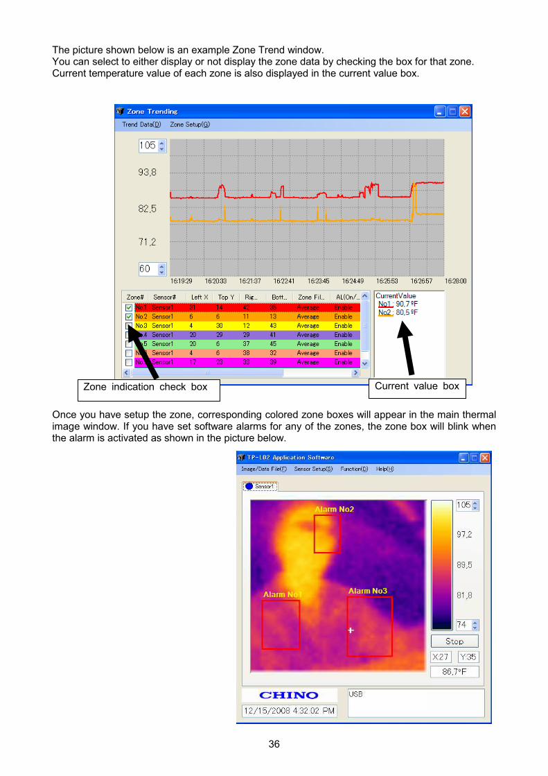
The picture shown below is an example Zone Trend window. You can select to either display or not display the zone data by checking the box for that zone. Current temperature value of each zone is also displayed in the current value box.
Once you have setup the zone, corresponding colored zone boxes will appear in the main thermal image window. If you have set software alarms for any of the zones, the zone box will blink when the alarm is activated as shown in the picture below.
Current value box Zone indication check box

37
4. Help (H)
Help Manual is displayed.
Version
The version information of the application software is shown.

38
� Troubleshooting
Symptoms Causes Measures
Cannot complete software installation
OS version may not be the latest. Update it to the latest version. Refer to the instruction manual (Page 4) for installation.
The custom USB cable is not connected properly.
Check the connection of the cable and Connect the custom USB cable properly.
The application software has not been installed.
Install the application software. Refer to the instruction manual (Page 4).
No Communications
The USB driver is not installed. Install the USB driver. Refer to the instruction manual for the application software.
The custom power cable is not connected properly.
Connect the custom power cable properly. Indicator lamp is not
lit The power supply has not been turned on.
Turn the power supply on.
Indicator lamp flashes Red once
Internal memory problem Contact to the nearest distributor.
Indicator lamp flashes Red twice
Abnormal Internal temperature Use the sensor within its operating ambient temperature range. Contact to the nearest distributor.


![3D Thermal Imaging: Fusion of Thermography and · PDF file3D Thermal Imaging: Fusion of Thermography and Depth ... image-processing techniques ... camera [13] All these multi-sensor](https://static.fdocuments.in/doc/165x107/5a9db4f97f8b9a85318bad6e/3d-thermal-imaging-fusion-of-thermography-and-thermal-imaging-fusion-of-thermography.jpg)

