Theory of Machine Student Manual
72
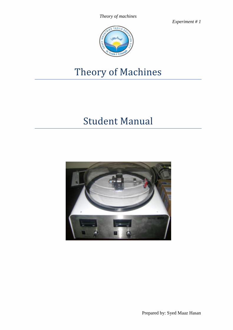
Theory of machines Experiment # 1 Prepared by: Syed Maaz Hasan Theory of Machines Student Manual
-
Upload
wellington-lima -
Category
Documents
-
view
234 -
download
11
Transcript of Theory of Machine Student Manual
Theory of machines
Experiment # 1
Prepared by: Syed Maaz Hasan
Theory of Machines
Student Manual
Theory of machines
Experiment # 1
Prepared by: Syed Maaz Hasan
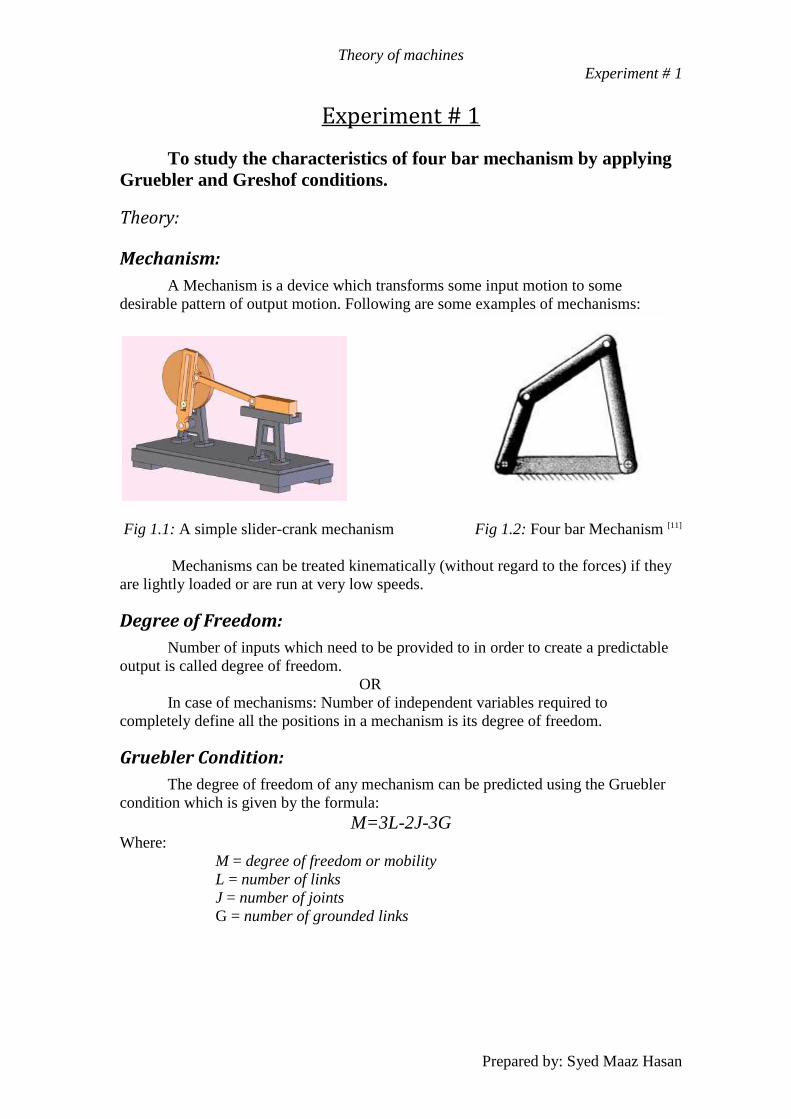
Experiment # 1
To study the characteristics of four bar mechanism by applying
Gruebler and Greshof conditions.
Theory:
Mechanism:
A Mechanism is a device which transforms some input motion to some
desirable pattern of output motion. Following are some examples of mechanisms:
Fig 1.1: A simple slider-crank mechanism Fig 1.2: Four bar Mechanism [11]
Mechanisms can be treated kinematically (without regard to the forces) if they
are lightly loaded or are run at very low speeds.
Degree of Freedom:
Number of inputs which need to be provided to in order to create a predictable
output is called degree of freedom.
OR
In case of mechanisms: Number of independent variables required to
completely define all the positions in a mechanism is its degree of freedom.
Gruebler Condition:
The degree of freedom of any mechanism can be predicted using the Gruebler
condition which is given by the formula:
M=3L-2J-3G Where:
M = degree of freedom or mobility
L = number of links
J = number of joints
G = number of grounded links
Theory of machines
Experiment # 1
Prepared by: Syed Maaz Hasan
Note that in any real mechanism, even if more than one link of the kinematic
chain is grounded, the net effect will be to create one larger, higher-order ground link,
as there can be only one ground plane. Thus G is always one, and Gruebler's equation
becomes:
M=3(L - 1) - 2J
Grashof Condition:
The Grashof condition is a very simple relationship which predicts the rotation
behavior or rotatability of a four bar linkage's inversions based only on the link
lengths.
Let: S = length of shortest link
L = length of longest link
P = length of one remaining link
Q = length of other remaining link
Then if: S + L ≤ P + Q
The linkage is Grashof and at least one link will be capable of making a full
revolution with respect to the ground plane. This is called a Class 1 kinematic chain. If
the inequality is not true, then the linkage is non-Grashof and no link will be capable of
a complete revolution relative to any other link. This is a Class II kinematic chain.
The motions possible from a four bar linkage will depend on both the Grashof
condition and the inversion chosen. The inversions will be defined with respect to the
shortest link. The motions are:
For the Class I case,
S + L < P + Q
Ground either link adjacent to the shortest and you get a crank-rocker, in which
the shortest link will fully rotate and the other link pivoted to ground will oscillate.
Ground the shortest link and you will get a double-crank, in which both links pivoted to
ground make complete revolutions as does the coupler. Ground the link opposite the
shortest and you will get a Grashof double-rocker, in which both links pivoted to
ground oscillate and only the coupler makes a full revolution.
For the Class II case,
S + L > P + Q
All inversions will be triple-rockers in which no link can fully rotate.
For the Class III case,
S + L = P + Q
Referred to as special-case Grashof and also as a Class III kinematic chain, all
inversions will be either double-cranks or crank-rockers but will have "change points"
twice per revolution of the input crank when the links all become collinear. At these
change points the output behavior will become indeterminate. [1]

Theory of machines
Experiment # 1
Prepared by: Syed Maaz Hasan
Apparatus:
Four Bar Mechanism
Tri Square/Foot Scale
Stopper
Fig 1.3: Four bar Mechanism available in lab
Procedure:
Count the number of links in a four bar mechanism.
Count the number of joints in the mechanism.
Using the Gruebler's equation: M=3(L - 1) - 2J calculate the degree of
freedom of the four bar mechanism.
Now, with the help of tri square/foot scale, measure the distance between each
hole in the mechanism and the corresponding link lengths which can be
obtained in the given four bar mechanism.
After each possible link length has been calculated, create all the possible link
length combinations by varying the link lengths using the stopper for the class I
case: S + L < P + Q
Similarly for the class II case, create all the possible link lengths which satisfy
the equation: S + L > P + Q
Finally for the class III case, try to create all the possible link combinations by
varying the link lengths which satisfy the equation:
S + L = P + Q
Theory of machines
Experiment # 1
Prepared by: Syed Maaz Hasan
If any one of the cases cannot be satisfied for the given four bar mechanism,
then mention the difficulty and discuss the solution for this problem.
Calculations:
Number of links: ________
Number of joints: ________
Gruebler's equation: __________________________
__________________________
Degree of Freedom: ________
Tables:
For Class I case:
Sr. No
Link 1 Length (Crank)
Link 2 Length
(Coupler)
Link 3 Length
(Rocker)
Link 4 Length
(Ground)
Crank Rotation
(degrees)
Rocker Rotation
(degrees)
For Class II case:
Sr. No
Link 1 Length (Crank)
Link 2 Length
(Coupler)
Link 3 Length
(Rocker)
Link 4 Length
(Ground)
Crank Rotation
(degrees)
Rocker Rotation
(degrees)
For Class III case:
Sr. No
Link 1 Length (Crank)
Link 2 Length
(Coupler)
Link 3 Length
(Rocker)
Link 4 Length
(Ground)
Crank Rotation
(degrees)
Rocker Rotation
(degrees)
Theory of machines
Experiment # 1
Prepared by: Syed Maaz Hasan
Discussion:
______________________________________________________________________
______________________________________________________________________
______________________________________________________________________
______________________________________________________________________
______________________________________________________________________
______________________________________________________________________
______________________________________________________________________
______________________________________________________________________
______________________________________________________________________
______________________________________________________________________
______________________________________________________________________
______________________________________________________________________
______________________________________________________________________
______________________________________________________________________
______________________________________________________________________
______________________________________________________________________
______________________________________________________________________
______________________________________________________________________
______________________________________________________________________
______________________________________________________________________
______________________________________________________________________
______________________________________________________________________
Theory of machines
Experiment # 2
Prepared by: Syed Maaz Hasan
Experiment # 2 To apply Grashof condition on a slider-crank mechanism and to
study the variation in velocity and acceleration of the slider when the
crank is rotated with a constant angular velocity.
Theory:
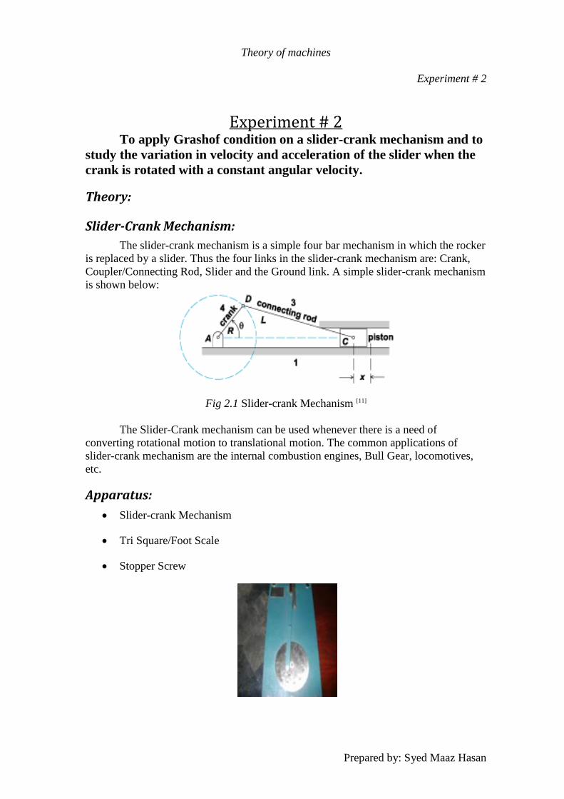
Slider-Crank Mechanism:
The slider-crank mechanism is a simple four bar mechanism in which the rocker
is replaced by a slider. Thus the four links in the slider-crank mechanism are: Crank,
Coupler/Connecting Rod, Slider and the Ground link. A simple slider-crank mechanism
is shown below:
Fig 2.1 Slider-crank Mechanism [11]
The Slider-Crank mechanism can be used whenever there is a need of
converting rotational motion to translational motion. The common applications of
slider-crank mechanism are the internal combustion engines, Bull Gear, locomotives,
etc.
Apparatus:
Slider-crank Mechanism
Tri Square/Foot Scale
Stopper Screw
Theory of machines
Experiment # 2
Prepared by: Syed Maaz Hasan
Procedure:
Count the number of links in the slider-crank mechanism.
Count the number of joints in the mechanism.
Using the Gruebler's equation: M=3(L - 1) - 2J calculate the degree of
freedom of the slider-crank mechanism.
Now, with the help of tri square/foot scale, measure the distance between the
each of the three holes present in the crank of the slider-crank mechanism.
These three holes represent the points where the stopper screw can be adjusted
to vary the link length of the crank.
Now, starting with zero, with the help of the angular scale available on the
crank, position the crank with an increment of every fifteen degrees and observe
the corresponding position of the slider. Note down these values in the table
available. Do this procedure for the whole 360 degrees.
Assuming an angular velocity of fifteen degrees per second, calculate the
velocities at each of the positions of fifteen degrees with the help of the
formula: (P2- P1)/ (T2 –T1) where
P2 = Final position of the slider.
P1 = Initial Position of the slider.
T2 –T1 = 1 second
After calculating the velocities of the slider at different points, calculate the
acceleration at the same points with the help of the formula: (V2- V1)/ (T2 –T1)
where
V2 = Final velocity of the slider.
V1 = Initial velocity of the slider.
T2 –T1 = 1 second
Finally draw graphs of position, velocity and acceleration of the slider with
respect to the position of the crank.
Apply the same procedure for the other two slider lengths.
Theory of machines
Experiment # 2
Prepared by: Syed Maaz Hasan
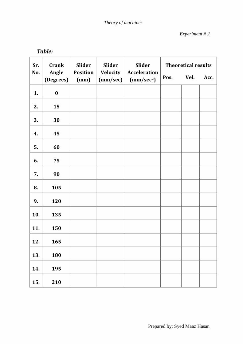
Table:
Sr.
No.
Crank
Angle
(Degrees)
Slider
Position
(mm)
Slider
Velocity
(mm/sec)
Slider
Acceleration
(mm/sec2)
Theoretical results
Pos. Vel. Acc.
1. 0
2. 15
3. 30
4. 45
5. 60
6. 75
7. 90
8. 105
9. 120
10. 135
11. 150
12. 165
13. 180
14. 195
15. 210

Theory of machines
Experiment # 2
Prepared by: Syed Maaz Hasan
Sr.
No.
Crank
Angle
(Degrees)
Slider
Position
(mm)
Slider
Velocity
(mm/sec)
Slider
Acceleration
(mm/sec2)
Theoretical results
Pos. Vel. Acc.
16. 225
17. 240
18. 255
19. 270
20. 285
21. 300
22. 315
23. 330
24. 345
Calculations:
Number of links: ________
Number of joints: ________
Gruebler's equation: __________________________
__________________________
Degree of Freedom: ________
Theory of machines
Experiment # 3
Prepared by: Syed Maaz Hasan
Experiment # 3 To study the variation in velocity and acceleration of the slider
when the crank is rotated with a constant angular velocity in a slotted
link slider-crank mechanism.
Theory:
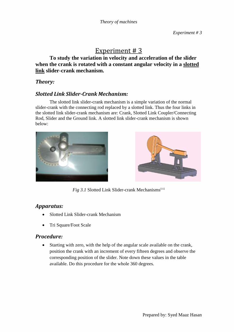
Slotted Link Slider-Crank Mechanism:
The slotted link slider-crank mechanism is a simple variation of the normal
slider-crank with the connecting rod replaced by a slotted link. Thus the four links in
the slotted link slider-crank mechanism are: Crank, Slotted Link Coupler/Connecting
Rod, Slider and the Ground link. A slotted link slider-crank mechanism is shown
below:
Fig 3.1 Slotted Link Slider-crank Mechanisms[11]
Apparatus:
Slotted Link Slider-crank Mechanism
Tri Square/Foot Scale
Procedure:
Starting with zero, with the help of the angular scale available on the crank,
position the crank with an increment of every fifteen degrees and observe the
corresponding position of the slider. Note down these values in the table
available. Do this procedure for the whole 360 degrees.
Theory of machines
Experiment # 3
Prepared by: Syed Maaz Hasan
Assuming an angular velocity of fifteen degrees per second, calculate the
velocities at each of the positions of fifteen degrees with the help of the
formula: (P2- P1)/ (T2 –T1) where
P2 = Final position of the slider.
P1 = Initial Position of the slider.
T2 –T1 = 1 second
After calculating the velocities of the slider at different points, calculate the
acceleration at the same points with the help of the formula: (V2- V1)/ (T2 –T1)
where
V2 = Final velocity of the slider.
V1 = Initial velocity of the slider.
T2 –T1 = 1 second
Then draw graphs of position, velocity and acceleration of the slider with
respect to the position of the crank.
Now compare the results obtained for the slotted link slider-crank mechanism
with those obtained in the previous experiment of simple slider-crank
mechanism and give some observations regarding the results.
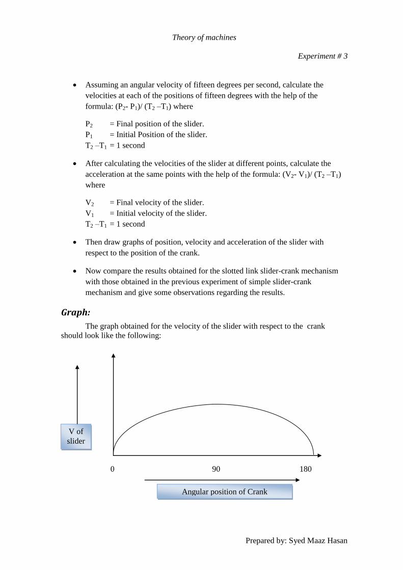
Graph:
The graph obtained for the velocity of the slider with respect to the crank
should look like the following:
V of
slider
0 90 180
Angular position of Crank

Theory of machines
Experiment # 3
Prepared by: Syed Maaz Hasan
Table:
Sr.
No.
Crank
Angle
(Degrees)
Slider
Position
(mm)
Slider
Velocity
(mm/sec)
Slider
Acceleration
(mm/sec2)
Theoretical results
Pos. Vel. Acc.
1. 0
2. 15
3. 30
4. 45
5. 60
6. 75
7. 90
8. 105
9. 120
10. 135
11. 150
12. 165
13. 180
14. 195
15. 210

Theory of machines
Experiment # 3
Prepared by: Syed Maaz Hasan
Sr.
No.
Crank
Angle
(Degrees)
Slider
Position
(mm)
Slider
Velocity
(mm/sec)
Slider
Acceleration
(mm/sec2)
Theoretical results
Pos. Vel. Acc.
16. 225
17. 240
18. 255
19. 270
20. 285
21. 300
22. 315
23. 330
24. 345
Observations:
______________________________________________________________________
______________________________________________________________________
______________________________________________________________________
______________________________________________________________________
______________________________________________________________________
______________________________________________________________________
______________________________________________________________________
______________________________________________________________________
______________________________________________________________________
______________________________________________________________________
Theory of machines
Experiment # 4
Prepared by: Syed Maaz Hasan
Experiment # 4
To study the relationship between motion of crank and the
connecting rod in a crank and connecting rod mechanism.
Theory:
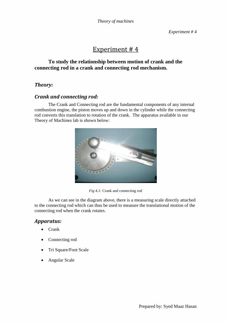
Crank and connecting rod:
The Crank and Connecting rod are the fundamental components of any internal
combustion engine, the piston moves up and down in the cylinder while the connecting
rod converts this translation to rotation of the crank. The apparatus available in our
Theory of Machines lab is shown below:
Fig 4.1: Crank and connecting rod
As we can see in the diagram above, there is a measuring scale directly attached
to the connecting rod which can thus be used to measure the translational motion of the
connecting rod when the crank rotates.
Apparatus:
Crank
Connecting rod
Tri Square/Foot Scale
Angular Scale
Theory of machines
Experiment # 4
Prepared by: Syed Maaz Hasan
Procedure:
Starting with zero, with the help of the angular scale available on the crank,
position the crank with an increment of every fifteen degrees and observe the
corresponding position of the connecting rod. Note down these values in the
table available. Do this procedure for the whole 360 degrees.
Assuming an angular velocity of fifteen degrees per second, calculate the
velocities at each of the positions of fifteen degrees with the help of the
formula: (P2- P1)/ (T2 –T1) where
P2 = Final position of the slider.
P1 = Initial Position of the slider.
T2 –T1 = 1 second
After calculating the velocities of the connecting rod at different points,
calculate the acceleration at the same points with the help of the formula:
(V2- V1)/ (T2 –T1)
where,
V2 = Final velocity of the slider.
V1 = Initial velocity of the slider.
T2 –T1 = 1 second
Then draw graphs of position, velocity and acceleration of the connecting rod
with respect to the position of the crank.
Now compare the results obtained for the crank and connecting-rod with those
obtained in the previous experiment of simple slider-crank mechanism plus the
slotted link slider-crank mechanism and give some observations regarding the
results.
In the end draw a graph showing the relationship of motion of the connecting
rod and the slider.
Graphs:
Theory of machines
Experiment # 4
Prepared by: Syed Maaz Hasan
Table:
Sr.
No.
Crank
Angle
(Degrees)
Slider
Position
(mm)
Slider
Velocity
(mm/sec)
Slider
Acceleration
(mm/sec2)
Theoretical results
Pos. Vel. Acc.
1. 0
2. 15
3. 30
4. 45
5. 60
6. 75
7. 90
8. 105
9. 120
10. 135
11. 150
12. 165
13. 180
14. 195
15. 210
Theory of machines
Experiment # 4
Prepared by: Syed Maaz Hasan
Sr.
No.
Crank
Angle
(Degrees)
Slider
Position
(mm)
Slider
Velocity
(mm/sec)
Slider
Acceleration
(mm/sec2)
Theoretical results
Pos. Vel. Acc.
16. 225
17. 240
18. 255
19. 270
20. 285
21. 300
22. 315
23. 330
24. 345
Observations:
______________________________________________________________________
______________________________________________________________________
______________________________________________________________________
______________________________________________________________________
______________________________________________________________________
______________________________________________________________________
______________________________________________________________________
______________________________________________________________________
______________________________________________________________________
______________________________________________________________________
______________________________________________________________________
Theory of machines
Experiment # 5
Prepared by: Syed Maaz Hasan
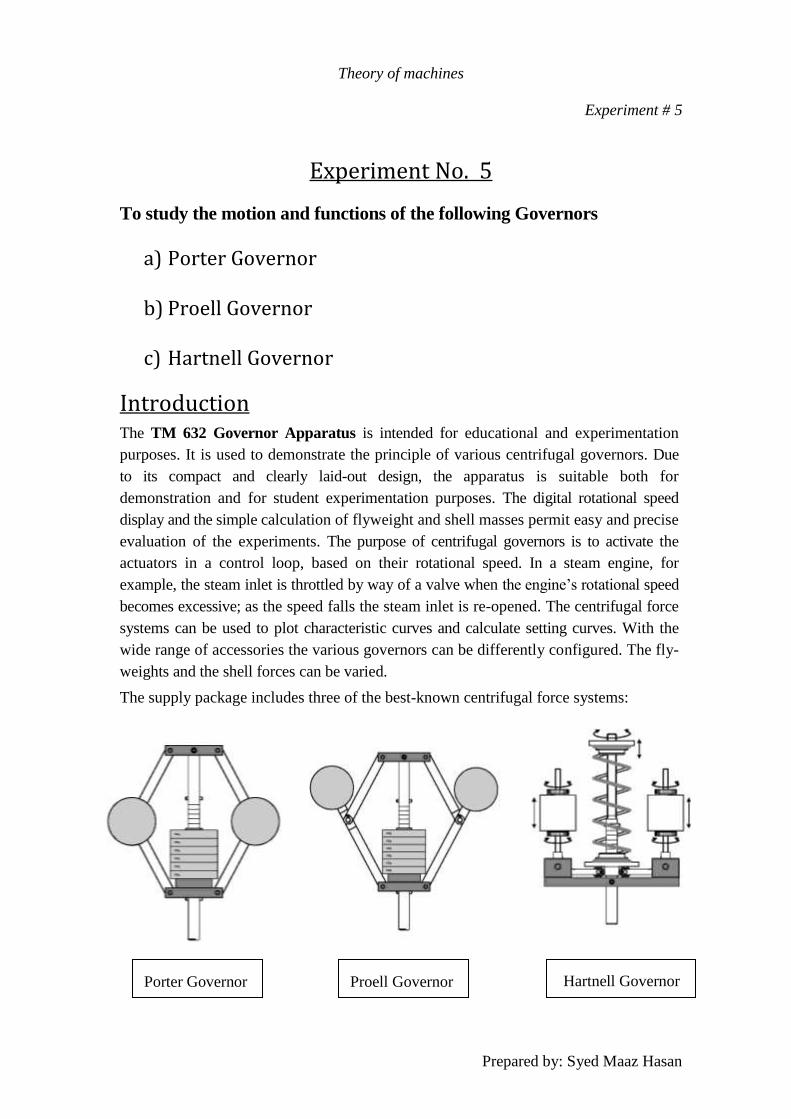
Experiment No. 5
To study the motion and functions of the following Governors
a) Porter Governor
b) Proell Governor
c) Hartnell Governor
Introduction The TM 632 Governor Apparatus is intended for educational and experimentation
purposes. It is used to demonstrate the principle of various centrifugal governors. Due
to its compact and clearly laid-out design, the apparatus is suitable both for
demonstration and for student experimentation purposes. The digital rotational speed
display and the simple calculation of flyweight and shell masses permit easy and precise
evaluation of the experiments. The purpose of centrifugal governors is to activate the
actuators in a control loop, based on their rotational speed. In a steam engine, for
example, the steam inlet is throttled by way of a valve when the engine’s rotational speed
becomes excessive; as the speed falls the steam inlet is re-opened. The centrifugal force
systems can be used to plot characteristic curves and calculate setting curves. With the
wide range of accessories the various governors can be differently configured. The fly-
weights and the shell forces can be varied.
The supply package includes three of the best-known centrifugal force systems:
Proell Governor
Hartnell Governor
Porter Governor

Theory of machines
Experiment # 5
Prepared by: Syed Maaz Hasan
Description of Apparatus
The base unit (1) contains the drive unit with an electronically controlled motor. The
motor is switched on and off with the motor buttons (2). The apparatus can only be
started up when the protective hood (3) is located in its retaining ring (4). The motor
speed is set steplessly with a 10-speed potentiometer (5). A digital tachometer (6) indicates
the rotational speed in rpm. A transparent protective hood (3) covers the rotating
centrifugal governor in operation.
The centrifugal force systems are inserted from above into a clamping spindle (7). When the
motor has been switched on and has reached lift-off speed, the shell (8) is lifted by the
centrifugal force acting on the flyweights (9). The travel is limited at the top and bottom
by pins (10), and can be read from the puncture marks (11) on the governor shaft (12). The
gap between the punctures is 5mm.
Theoretical Background
A technically important special case in terms of motion of
bodies is orbital motion. This is motion on a curved path with
constant radius of curvature or path radius r.
To derive the accelerations occurring for one point on an orbital
path, the position of the point P is defined by its radius vector
_r. In Cartesian path coordinates the radius vector can be
written as follows
Porter Governor

Theory of machines
Experiment # 5
Prepared by: Syed Maaz Hasan
In this, r is the radius of the orbital path and ϕ the angle of rotation at the point in time t.
The velocity vector v_ is obtained by differentiation by time t
The vector
has the
direction of a tangent on the orbital path and is termed the
tangential unit vector. Its amount is 1.
If for cp the angular velocity co is inserted, the path velocity or
circumferential velocity
The acceleration vector is obtained by again differentiating
The acceleration vector can be written as the sum of two vectors
The vector in the first summand is again the tangential unit vector in tangential
direction. The vector
points to the midpoint of the orbital path and is termed
normal unit vector.
Thus, two acceleration components act on one point
on an orbital path:
- A path acceleration in tangential direction

Theory of machines
Experiment # 5
Prepared by: Syed Maaz Hasan
- A normal or radial acceleration in the direction of
the midpoint of the orbital path
The angular velocity ω in rad/s is calculated from the
rotational speed n in rpm
In a motion with constant angular velocity, the tangential acceleration is equal to
zero. Only the normal acceleration an remains.
Kinetics and kinematics of the centrifugal force systems
Porter Governor
From the geometry and the isolated segments of the
system, and taking account of the general kinetic and
kinematic relations, equations can be drawn up with
which the governor can be designed. The adjacent
diagram shows the geometry of the Porter governor. In
the present case, the arm lengths and the distances a of
their pivot points to the rotational axis are equal.
System I
Balance of horizontal forces:
Balance of vertical forces:
Theory of machines
Experiment # 5
Prepared by: Syed Maaz Hasan
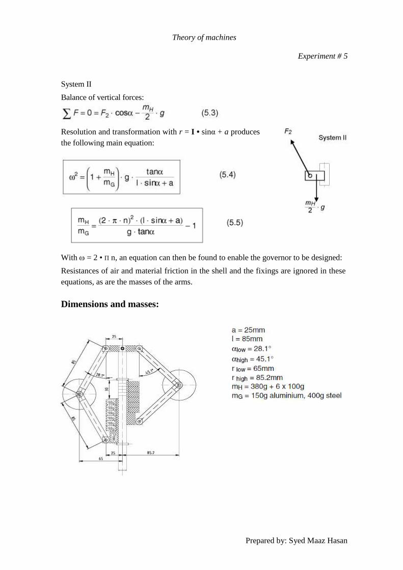
System II
Balance of vertical forces:
Resolution and transformation with r = I • sinα + a produces
the following main equation:
With = 2 • Π n, an equation can then be found to enable the governor to be designed:
Resistances of air and material friction in the shell and the fixings are ignored in these
equations, as are the masses of the arms.
Dimensions and masses:
Theory of machines
Experiment # 5
Prepared by: Syed Maaz Hasan
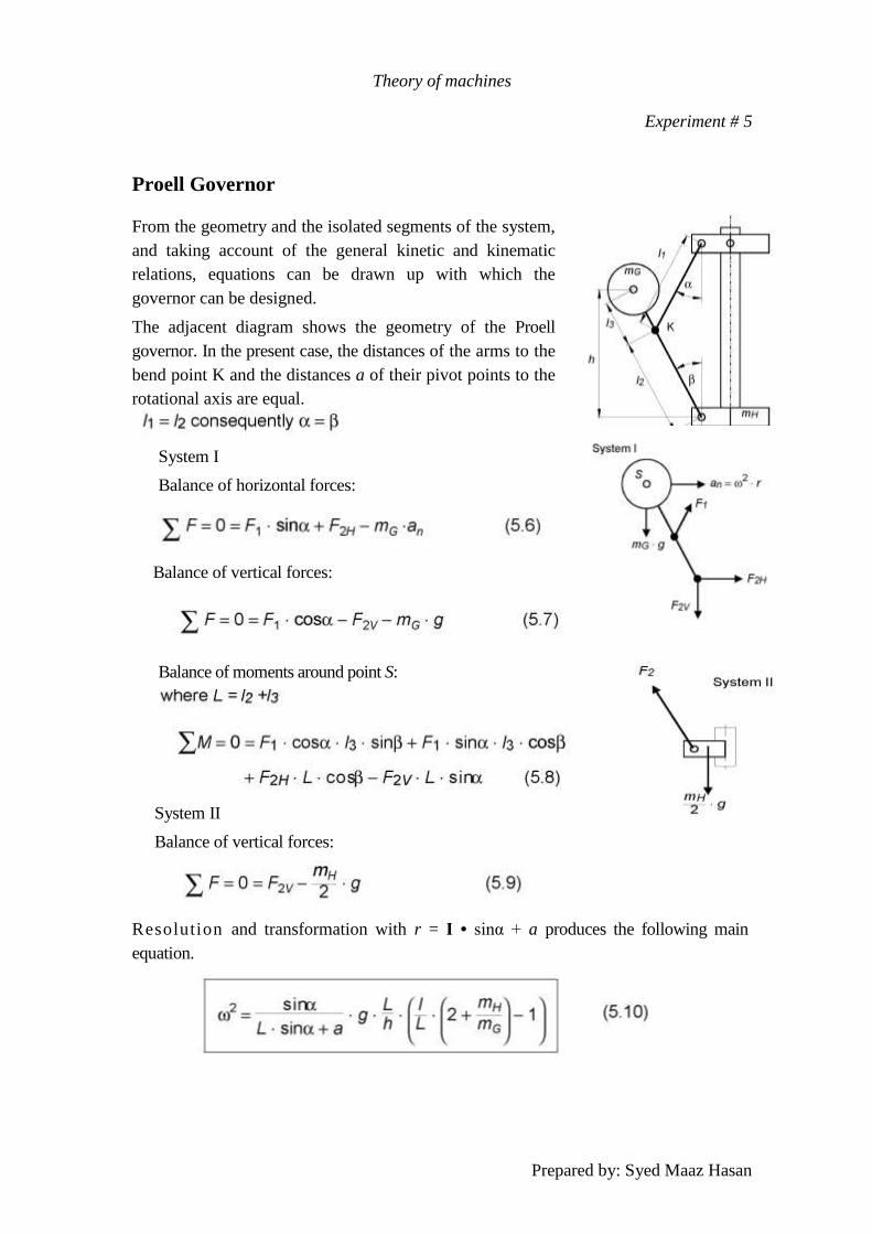
Proell Governor
From the geometry and the isolated segments of the system,
and taking account of the general kinetic and kinematic
relations, equations can be drawn up with which the
governor can be designed.
The adjacent diagram shows the geometry of the Proell
governor. In the present case, the distances of the arms to the
bend point K and the distances a of their pivot points to the
rotational axis are equal.
System I
Balance of horizontal forces:
Balance of vertical forces:
Balance of moments around point S:
System II
Balance of vertical forces:
Resolution and transformation with r = I • sinα + a produces the following main
equation.

Theory of machines
Experiment # 5
Prepared by: Syed Maaz Hasan
With = 2 • Π n, an equation can then be found to enable the governor to be designed:
Resistances of air and material friction in the shell and the fixings are ignored in these
equations, as are the masses of the arms.
Dimensions and masses:
Hartnell Governor
From the geometry and the isolated segments of the system, and taking account of the
general kinetic and kinematic relations, equations can be drawn up with which the
governor can be designed.
The adjacent diagram shows the geometry of the Hartnell Governor.
System I
Balance of moments around point S:
Theory of machines
Experiment # 5
Prepared by: Syed Maaz Hasan
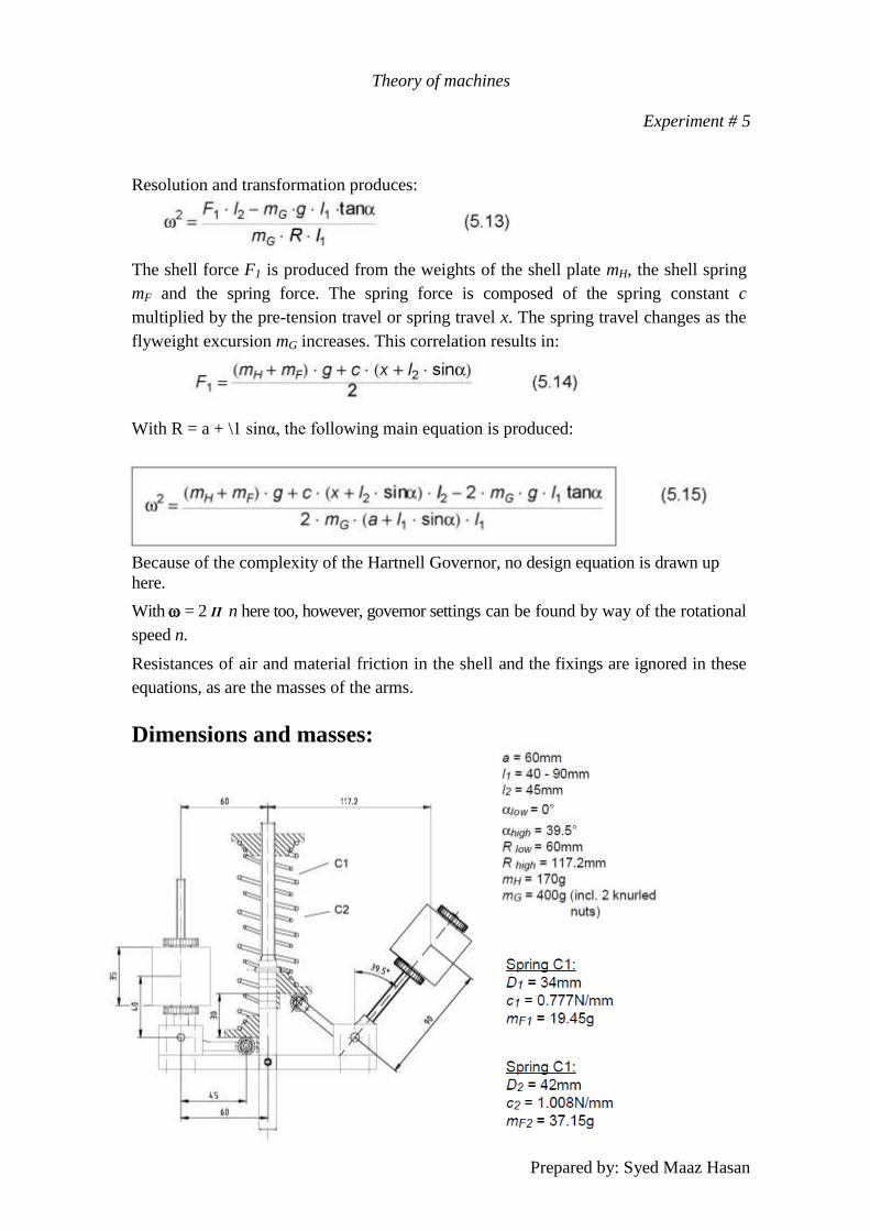
Resolution and transformation produces:
The shell force F1 is produced from the weights of the shell plate mH, the shell spring
mF and the spring force. The spring force is composed of the spring constant c
multiplied by the pre-tension travel or spring travel x. The spring travel changes as the
flyweight excursion mG increases. This correlation results in:
With R = a + \1 sinα, the following main equation is produced:
Because of the complexity of the Hartnell Governor, no design equation is drawn up
here.
With = 2 Π n here too, however, governor settings can be found by way of the rotational
speed n.
Resistances of air and material friction in the shell and the fixings are ignored in these
equations, as are the masses of the arms.
Dimensions and masses:
Theory of machines
Experiment # 5
Prepared by: Syed Maaz Hasan
Performing the experiments:
In performing the experiments a number of governor characteristic curves are recorded
and compared with the corresponding calculated curves.
- Insert the centrifugal force system (see Chapter 4.2), making sure the centrifugal
governor is fitted firmly in the clamping spindle.
- Configure the centrifugal governor (see Chapter 4.3); Only ever mount masses mG of the
same size on the governor arms. Keep the distance l1 on the governor arms of the Hartnell
governor constant.
- Place the protective hood in the retaining ring and start the apparatus (see Chapter 4.1).
- Slowly increase the rotational speed. As soon as the governor lifts, make note of the lift-
off speed.
- Always raise the governor from read mark to read mark (5mm) and note the relevant
rotational speeds.
Theory of machines
Experiment # 5
Prepared by: Syed Maaz Hasan
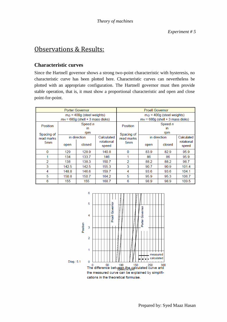
Observations & Results:
Characteristic curves
Since the Hartnell governor shows a strong two-point characteristic with hysteresis, no
characteristic curve has been plotted here. Characteristic curves can nevertheless be
plotted with an appropriate configuration. The Hartnell governor must then provide
stable operation, that is, it must show a proportional characteristic and open and close
point-for-point.
Theory of machines
Experiment # 5
Prepared by: Syed Maaz Hasan
Setting curves
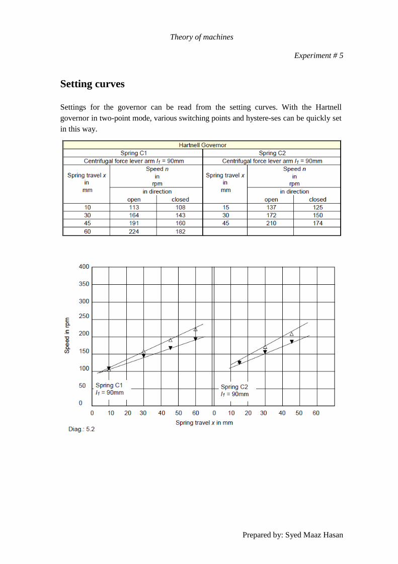
Settings for the governor can be read from the setting curves. With the Hartnell
governor in two-point mode, various switching points and hystere-ses can be quickly set
in this way.
Theory of machines
Experiment # 5
Prepared by: Syed Maaz Hasan
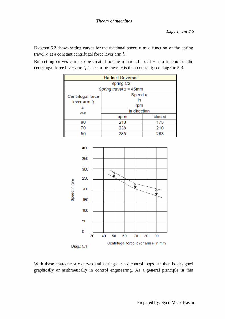
Diagram 5.2 shows setting curves for the rotational speed n as a function of the spring
travel x, at a constant centrifugal force lever arm l1.
But setting curves can also be created for the rotational speed n as a function of the
centrifugal force lever arm l1. The spring travel x is then constant; see diagram 5.3.
With these characteristic curves and setting curves, control loops can then be designed
graphically or arithmetically in control engineering. As a general principle in this
Theory of machines
Experiment # 5
Prepared by: Syed Maaz Hasan
context, the higher the governor gain, the more accurately it will operate. There is,
however, a risk that with excessive gain the governor will become unstable. The gain of
a governor is seen from the steepness of its characteristic curve.
The setting curves for the Hartnell Governor show very clearly that the spread of the
curves is mainly dependent on the pre-tension of the spring, while the rotational speed
shift is a function of the centrifugal force.
Theory of machines
Experiment # 5
Prepared by: Syed Maaz Hasan
Theory of machines
Experiment # 6
Prepared by: Syed Maaz Hasan
Experiment No. 6.
Gyroscope
To verify the Gyroscopic Effect
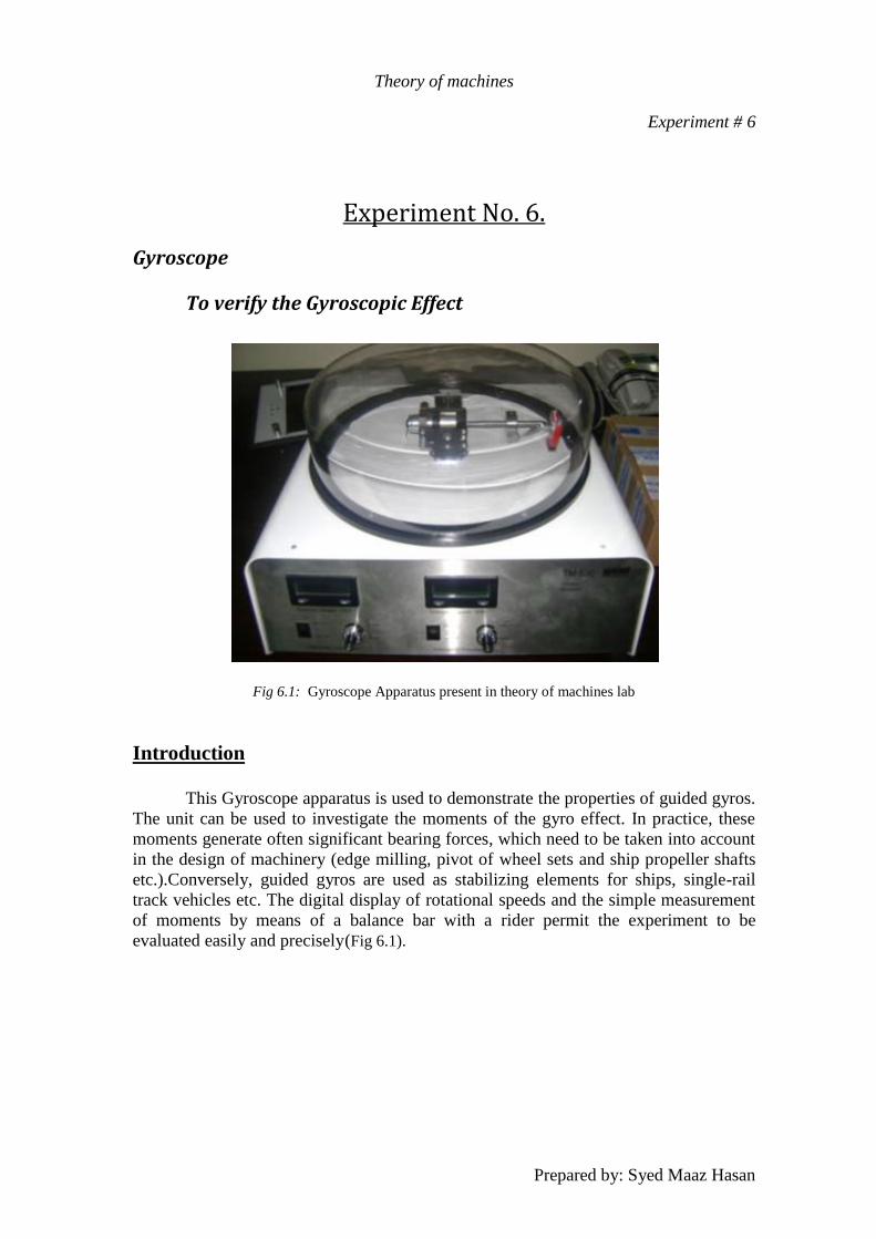
Fig 6.1: Gyroscope Apparatus present in theory of machines lab
Introduction
This Gyroscope apparatus is used to demonstrate the properties of guided gyros.
The unit can be used to investigate the moments of the gyro effect. In practice, these
moments generate often significant bearing forces, which need to be taken into account
in the design of machinery (edge milling, pivot of wheel sets and ship propeller shafts
etc.).Conversely, guided gyros are used as stabilizing elements for ships, single-rail
track vehicles etc. The digital display of rotational speeds and the simple measurement
of moments by means of a balance bar with a rider permit the experiment to be
evaluated easily and precisely (Fig 6.1).
Theory of machines
Experiment # 6
Prepared by: Syed Maaz Hasan
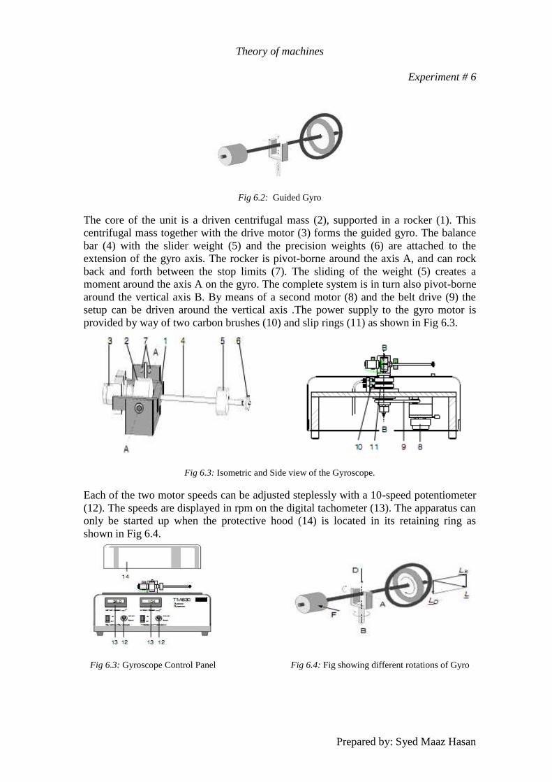
Fig 6.2: Guided Gyro
The core of the unit is a driven centrifugal mass (2), supported in a rocker (1). This
centrifugal mass together with the drive motor (3) forms the guided gyro. The balance
bar (4) with the slider weight (5) and the precision weights (6) are attached to the
extension of the gyro axis. The rocker is pivot-borne around the axis A, and can rock
back and forth between the stop limits (7). The sliding of the weight (5) creates a
moment around the axis A on the gyro. The complete system is in turn also pivot-borne
around the vertical axis B. By means of a second motor (8) and the belt drive (9) the
setup can be driven around the vertical axis .The power supply to the gyro motor is
provided by way of two carbon brushes (10) and slip rings (11) as shown in Fig 6.3.
Fig 6.3: Isometric and Side view of the Gyroscope.
Each of the two motor speeds can be adjusted steplessly with a 10-speed potentiometer
(12). The speeds are displayed in rpm on the digital tachometer (13). The apparatus can
only be started up when the protective hood (14) is located in its retaining ring as
shown in Fig 6.4.
Fig 6.3: Gyroscope Control Panel Fig 6.4: Fig showing different rotations of Gyro
Theory of machines
Experiment # 6
Prepared by: Syed Maaz Hasan
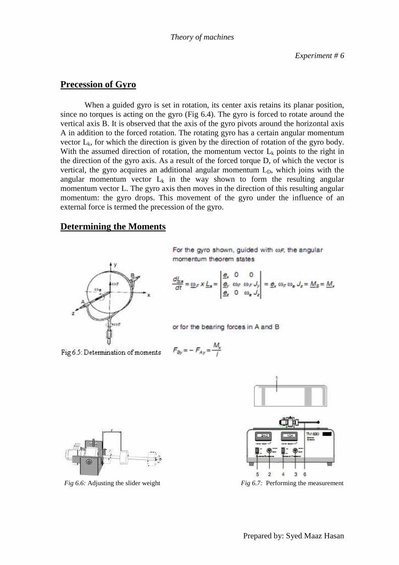
Precession of Gyro
When a guided gyro is set in rotation, its center axis retains its planar position,
since no torques is acting on the gyro (Fig 6.4). The gyro is forced to rotate around the
vertical axis B. It is observed that the axis of the gyro pivots around the horizontal axis
A in addition to the forced rotation. The rotating gyro has a certain angular momentum
vector Lk, for which the direction is given by the direction of rotation of the gyro body.
With the assumed direction of rotation, the momentum vector Lk points to the right in
the direction of the gyro axis. As a result of the forced torque D, of which the vector is
vertical, the gyro acquires an additional angular momentum LD, which joins with the
angular momentum vector Lk in the way shown to form the resulting angular
momentum vector L. The gyro axis then moves in the direction of this resulting angular
momentum: the gyro drops. This movement of the gyro under the influence of an
external force is termed the precession of the gyro.
Determining the Moments
Fig 6.6: Adjusting the slider weight Fig 6.7: Performing the measurement
Theory of machines
Experiment # 6
Prepared by: Syed Maaz Hasan
Experiment Procedure Adjusting the slider weight (Fig 6.6)
Release the slider weight by loosening the grub screw.
Set the desired radius r (max. 95 mm).
Tighten the grub screw
Performing the measurement (Fig 6.7)
Place the protective hood (1) in the retaining ring.
Turn the two speed potentiometers (2+3) to zero.
Switch on the motor for the gyro (precession)(switch 4).
With the speed potentiometer (3) runs up to the desired rotational speed.
Switch on the motor for the frame (gyroscope) (switch 5).
With the speed potentiometer (2) increase the rotational speed until the balance
bar (6) is horizontally aligned.
Make a note of both rotational speeds.
Experimental Verification
In the experiments the slider weight is set to various radii (r = 25 mm, 50 mm,
75 mm, 95 mm). The mass of the slider weight (m = 65.6 g), the acceleration due to
gravity g, and the radius r of the slider weight produce the moment MW dictated by the
balance bar:
MW = m ⋅ g ⋅ r = 0.0656kg ⋅ 9.81m⁄s2⋅ r = 0.6435N ⋅ r This moment MW is counteracted by the gyroscopic moment, causing the balance bar to
be lifted to the horizontal position. The theoretical gyroscopic moment Mk is calculated
from the rotational speed of the frame nF,the rotational speed of the gyro ne and the
mass moment of inertia of the gyro Jz
(Jz = 375 cm2g) as follows:
Mk = ωF.ωe.Jz = 2πnF/60⋅2πne/60⋅ 0.0000375 kg m2 The measurement and calculation results arecompared in the following table.
Theory of machines
Experiment # 6
Prepared by: Syed Maaz Hasan
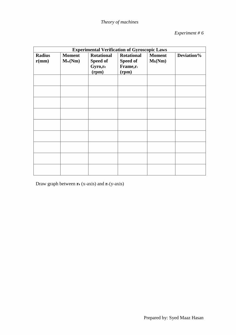
Experimental Verification of Gyroscopic Laws
Radius
r(mm)
Moment
Mw(Nm)
Rotational
Speed of
Gyro,re
(rpm)
Rotational
Speed of
Frame,rF
(rpm)
Moment
Mk(Nm)
Deviation%
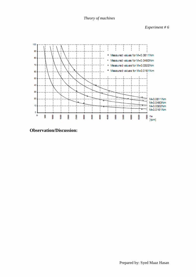
Draw graph between re (x-axis) and rF (y-axis)
Theory of machines
Experiment # 6
Prepared by: Syed Maaz Hasan
Observation/Discussion:
Theory of machines
Descriptions
Prepared by: Syed Maaz Hasan
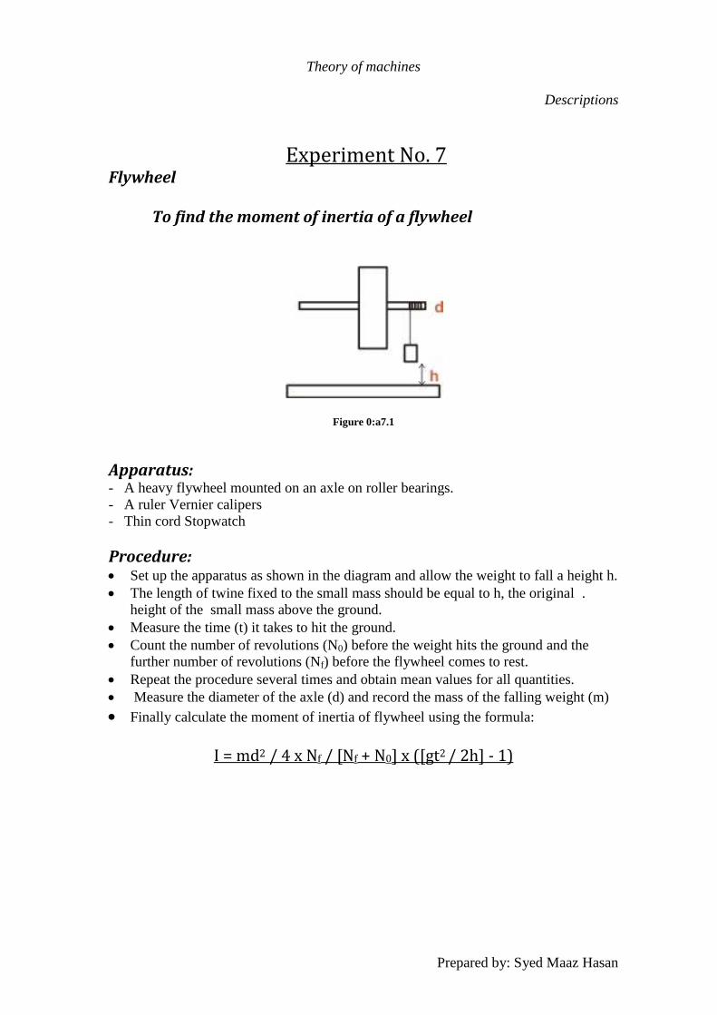
Experiment No. 7 Flywheel To find the moment of inertia of a flywheel
Figure 0:a7.1
Apparatus: - A heavy flywheel mounted on an axle on roller bearings.
- A ruler Vernier calipers
- Thin cord Stopwatch
Procedure: Set up the apparatus as shown in the diagram and allow the weight to fall a height h.
The length of twine fixed to the small mass should be equal to h, the original .
height of the small mass above the ground.
Measure the time (t) it takes to hit the ground.
Count the number of revolutions (N0) before the weight hits the ground and the
further number of revolutions (Nf) before the flywheel comes to rest.
Repeat the procedure several times and obtain mean values for all quantities.
Measure the diameter of the axle (d) and record the mass of the falling weight (m)
Finally calculate the moment of inertia of flywheel using the formula:
I = md2 / 4 x Nf / [Nf + N0] x ([gt2 / 2h] - 1)
Theory of machines
Descriptions
Prepared by: Syed Maaz Hasan
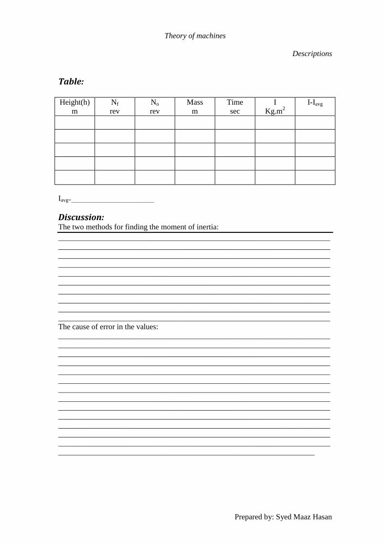
Table: Height(h)
m
Nf
rev
No
rev
Mass
m
Time
sec
I
Kg.m2
I-Iavg
Iavg=________________________________
Discussion: The two methods for finding the moment of inertia:
______________________________________________________________________
______________________________________________________________________
______________________________________________________________________
______________________________________________________________________
______________________________________________________________________
______________________________________________________________________
______________________________________________________________________
______________________________________________________________________
______________________________________________________________________
______________________________________________________________________
The cause of error in the values:
______________________________________________________________________
______________________________________________________________________
______________________________________________________________________
______________________________________________________________________
______________________________________________________________________
______________________________________________________________________
______________________________________________________________________
______________________________________________________________________
______________________________________________________________________
______________________________________________________________________
______________________________________________________________________
______________________________________________________________________
______________________________________________________________________
__________________________________________________________________
Theory of machines
Descriptions
Prepared by: Syed Maaz Hasan
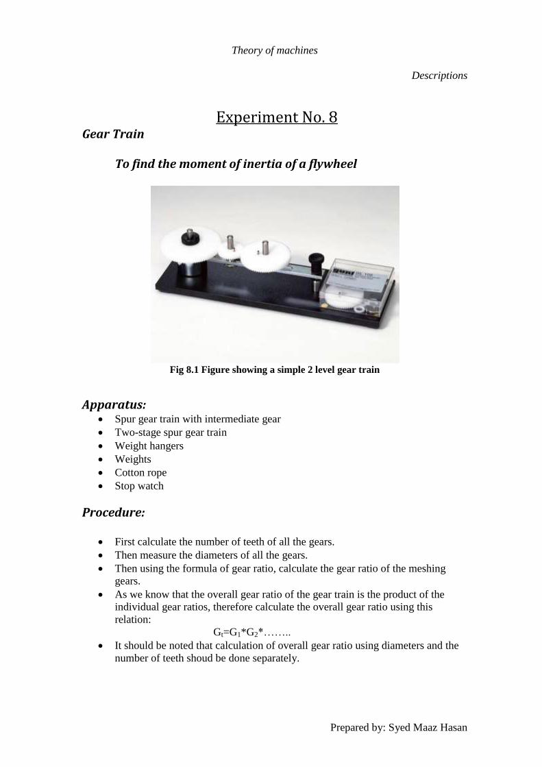
Experiment No. 8 Gear Train To find the moment of inertia of a flywheel
Fig 8.1 Figure showing a simple 2 level gear train
Apparatus: Spur gear train with intermediate gear
Two-stage spur gear train
Weight hangers
Weights
Cotton rope
Stop watch
Procedure:
First calculate the number of teeth of all the gears.
Then measure the diameters of all the gears.
Then using the formula of gear ratio, calculate the gear ratio of the meshing
gears.
As we know that the overall gear ratio of the gear train is the product of the
individual gear ratios, therefore calculate the overall gear ratio using this
relation:
Gt=G1*G2*……..
It should be noted that calculation of overall gear ratio using diameters and the
number of teeth shoud be done separately.
Theory of machines
Descriptions
Prepared by: Syed Maaz Hasan
Next calculate the gear ratio using the relation of number of revolutions. i.e. for
input of one revolution what are the number of revolutions at the output.
After that calculate the overall gear ratio using the relation of:
W1/W2 .
Where W is the speed of the individual gears. This can either be done through
tacometer OR by hanging weights at the input and output pulleys; then placing
them at mean position and finally allowing the weights to fall freely. Finally
measure the distance the weights moved from mean positions and calculate the
ratio.
Finally compare the overall gear ratios obtained through the above mentioned
methods and calculate the error.
Table:
Method G1 G2 Overall Gtot-Gavg
Dia
Radius
N (Rev)
No of Teeth
Speed
Gavg= Average of all gear ratios
Discussion: How to find radius of hidden gear:
______________________________________________________________________
______________________________________________________________________
______________________________________________________________________
______________________________________________________________________
______________________________________________________________________
______________________________________________________________________
______________________________________________________________________
______________________________________________________________________
______________________________________________________________________
______________________________________________________________________
The cause of error in the values:
______________________________________________________________________
______________________________________________________________________
______________________________________________________________________
______________________________________________________________________
Theory of machines
Descriptions
Prepared by: Syed Maaz Hasan
Description of other Lab Equipment Available in Theory of Machines lab
Equipment # 1
Spur Gear Model
Gears:
A gear is a rotating machine part having cut teeth, or cogs, which mesh with
another toothed part in order to transmit torque. Two or more gears working in tandem
are called a transmission and can produce a mechanical advantage through a gear ratio
and thus may be considered a simple machine. Geared devices can change the speed,
magnitude, and direction of a power source. The most common situation is for a gear to
mesh with another gear, however a gear can also mesh a non-rotating toothed part,
called a rack, thereby producing translation instead of rotation.
The gears in a transmission are analogous to the wheels in a pulley. An
advantage of gears is that the teeth of a gear prevent slipping.
When two gears of unequal number of teeth are combined a mechanical
advantage is produced, with both the rotational speeds and the torques of the two gears
differing in a simple relationship.
In transmissions which offer multiple gear ratios, such as bicycles and cars, the
term gear, as in first gear, refers to a gear ratio rather than an actual physical gear. The
term is used to describe similar devices even when gear ratio is continuous rather than
discrete, or when the device does not actually contain any gears, as in a continuously
variable transmission. [10]
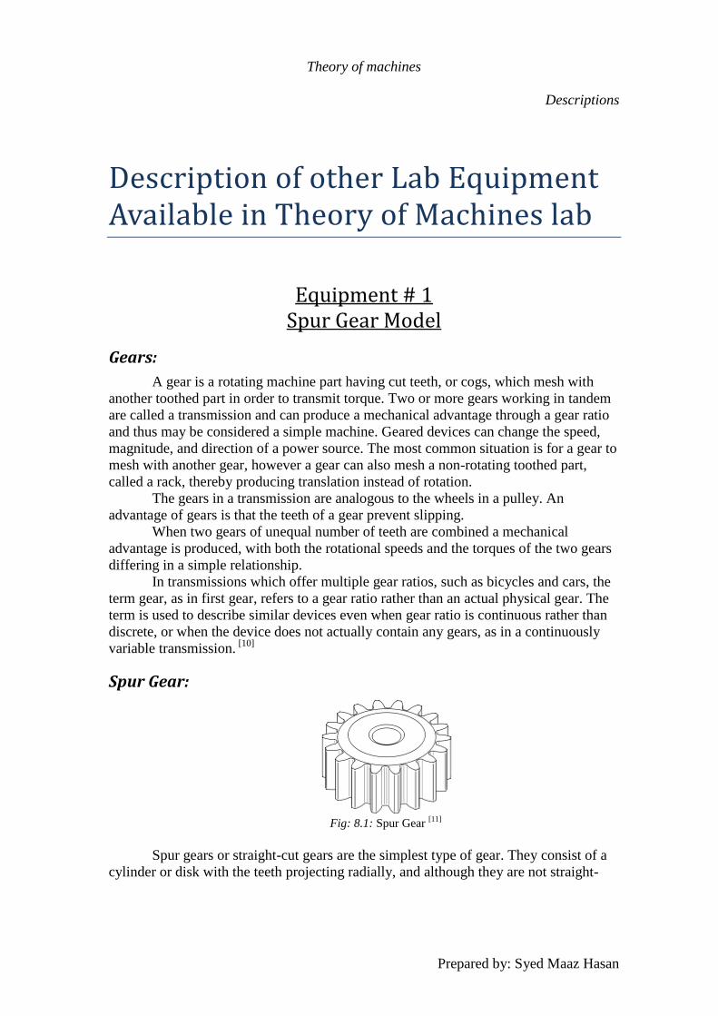
Spur Gear:
Fig: 8.1: Spur Gear
[11]
Spur gears or straight-cut gears are the simplest type of gear. They consist of a
cylinder or disk with the teeth projecting radially, and although they are not straight-

Theory of machines
Descriptions
Prepared by: Syed Maaz Hasan
sided in form, the edge of each tooth is straight and aligned parallel to the axis of
rotation. These gears can be meshed together correctly only if they are fitted to parallel
axles. [11]
Fig: 8.2: Spur Gear model in our lab.
Specifications:
Number of teeth:
Pinion Gear = 23
Spur Gear = 33
Gear ratio:
Pinion driving = 23/33 = 0.7
Spur Gear driving = 33/23 = 1.43
Shaft centre to centre distance
= 5.5 cm
Gear Pitch diameter
Pinion Gear = 4.52 cm
Spur Gear = 6.48 cm
Usage:
Spur gears are the most common types of gearing available, Their main
attributes are:
Simple design
Cheap manufacturing
Due to these two attributes, these gears are found everywhere, from automobile gear
box to lathe machines. These gears are found everywhere.
Theory of machines
Descriptions
Prepared by: Syed Maaz Hasan
Equipment # 2
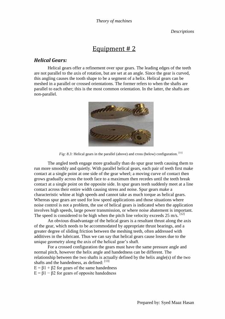
Helical Gears:
Helical gears offer a refinement over spur gears. The leading edges of the teeth
are not parallel to the axis of rotation, but are set at an angle. Since the gear is curved,
this angling causes the tooth shape to be a segment of a helix. Helical gears can be
meshed in a parallel or crossed orientations. The former refers to when the shafts are
parallel to each other; this is the most common orientation. In the latter, the shafts are
non-parallel.
Fig: 8.3: Helical gears in the parallel (above) and cross (below) configuration. [11]
The angled teeth engage more gradually than do spur gear teeth causing them to
run more smoothly and quietly. With parallel helical gears, each pair of teeth first make
contact at a single point at one side of the gear wheel; a moving curve of contact then
grows gradually across the tooth face to a maximum then recedes until the teeth break
contact at a single point on the opposite side. In spur gears teeth suddenly meet at a line
contact across their entire width causing stress and noise. Spur gears make a
characteristic whine at high speeds and cannot take as much torque as helical gears.
Whereas spur gears are used for low speed applications and those situations where
noise control is not a problem, the use of helical gears is indicated when the application
involves high speeds, large power transmission, or where noise abatement is important.
The speed is considered to be high when the pitch line velocity exceeds 25 m/s. [12]
An obvious disadvantage of the helical gears is a resultant thrust along the axis
of the gear, which needs to be accommodated by appropriate thrust bearings, and a
greater degree of sliding friction between the meshing teeth, often addressed with
additives in the lubricant. Thus we can say that helical gears cause losses due to the
unique geometry along the axis of the helical gear’s shaft.
For a crossed configuration the gears must have the same pressure angle and
normal pitch, however the helix angle and handedness can be different. The
relationship between the two shafts is actually defined by the helix angle(s) of the two
shafts and the handedness, as defined: [13]
E = β1 + β2 for gears of the same handedness
E = β1 − β2 for gears of opposite handedness
Theory of machines
Descriptions
Prepared by: Syed Maaz Hasan
Where, β is the helix angle for the gear. The crossed configuration is less
mechanically sound because there is only a point contact between the gears, whereas in
the parallel configuration there is a line contact. [13]
Quite commonly helical gears are used with the helix angle of one having the
negative of the helix angle of the other; such a pair might also be referred to as having a
right-handed helix and a left-handed helix of equal angles. The two equal but opposite
angles add to zero: the angle between shafts is zero – that is, the shafts are parallel.
Where the sum or the difference (as described in the equations above) is not zero the
shafts are crossed. For shafts crossed at right angles the helix angles are of the same
hand because they must add to 90 degrees.
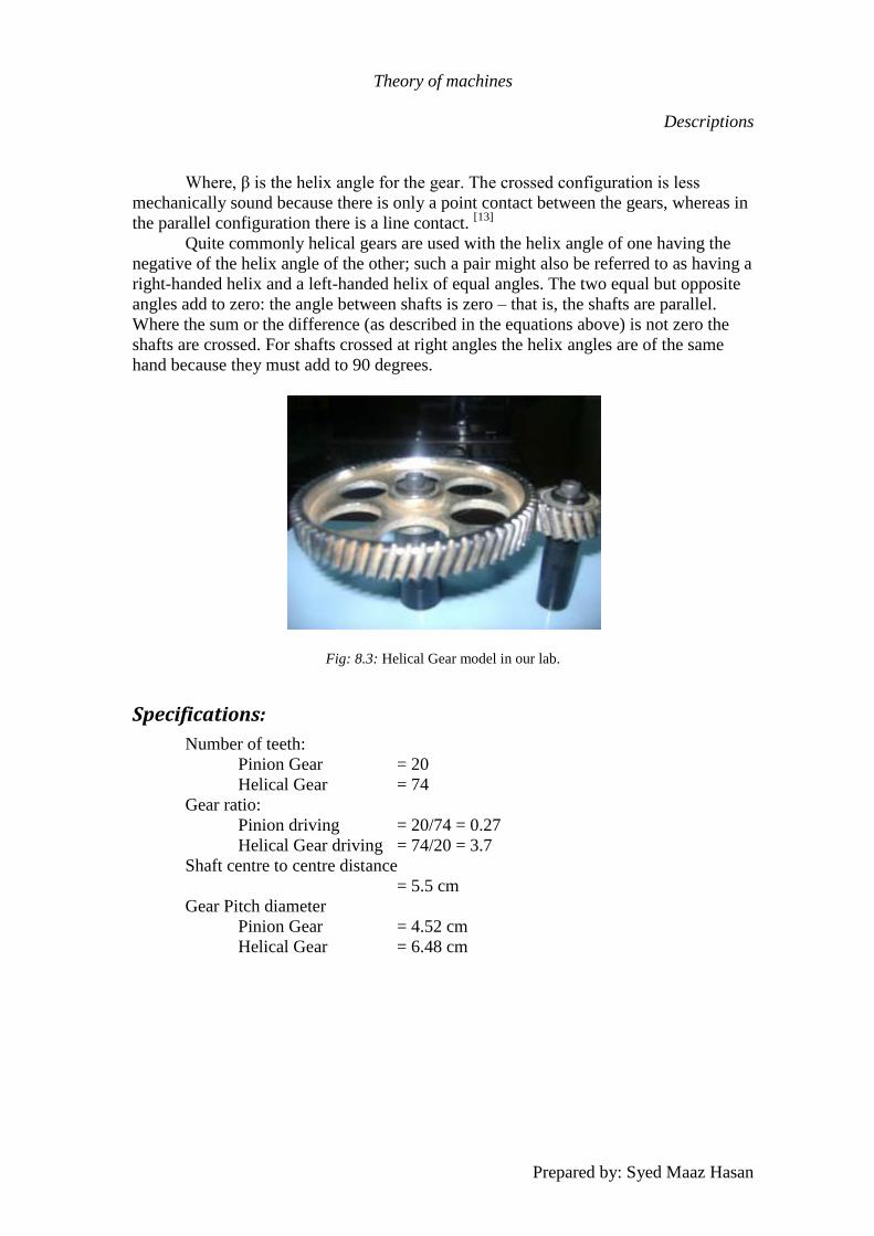
Fig: 8.3: Helical Gear model in our lab.
Specifications:
Number of teeth:
Pinion Gear = 20
Helical Gear = 74
Gear ratio:
Pinion driving = 20/74 = 0.27
Helical Gear driving = 74/20 = 3.7
Shaft centre to centre distance
= 5.5 cm
Gear Pitch diameter
Pinion Gear = 4.52 cm
Helical Gear = 6.48 cm

Theory of machines
Descriptions
Prepared by: Syed Maaz Hasan
Equipment # 3
Bevel Gears:
Fig 8.3: Bevel Gears [11]
Two important concepts in gearing are pitch surface and pitch angle. The pitch
surface of a gear is the imaginary toothless surface that you would have by averaging
out the peaks and valleys of the individual teeth. The pitch surface of an ordinary gear
is the shape of a cylinder. The pitch angle of a gear is the angle between the face of the
pitch surface and the axis.
The most familiar kinds of bevel gears have pitch angles of less than 90 degrees
and therefore are cone-shaped. This type of bevel gear is called external because the
gear teeth point outward. The pitch surfaces of meshed external bevel gears are coaxial
with the gear shafts; the apexes of the two surfaces are at the point of intersection of the
shaft axes.
Bevel gears that have pitch angles of greater than ninety degrees have teeth that
point inward and are called internal bevel gears.
Bevel gears that have pitch angles of exactly 90 degrees have teeth that point
outward parallel with the axis and resemble the points on a crown. That's why this type
of bevel gear is called a crown gear.
Miter gears are mating bevel gears with equal numbers of teeth and with axes at
right angles.
Skew bevel gears are those for which the corresponding crown gear has teeth
that are straight and oblique.
Teeth:
There are two issues regarding tooth shape. One is the cross-sectional profile of
the individual tooth. The other is the line or curve on which the tooth is set on the face
Theory of machines
Descriptions
Prepared by: Syed Maaz Hasan
of the gear: in other words the line or curve along which the cross-sectional profile is
projected to form the actual three-dimensional shape of the tooth. The primary effect of
both the cross-sectional profile and the tooth line or curve is on the smoothness of
operation of the gears. Some result in a smoother gear action than others.
Tooth line:
The teeth on bevel gears can be straight, spiral or "zero".
Straight tooth lines:
In straight bevel gears the teeth are straight and parallel to the generators of the
cone. This is the simplest form of bevel gear. It resembles a spur gear, only conical
rather than cylindrical. The gears in the floodgate picture are straight bevel gears. In
straight, when each tooth engages it impacts the corresponding tooth and simply
curving the gear teeth can solve the problem.
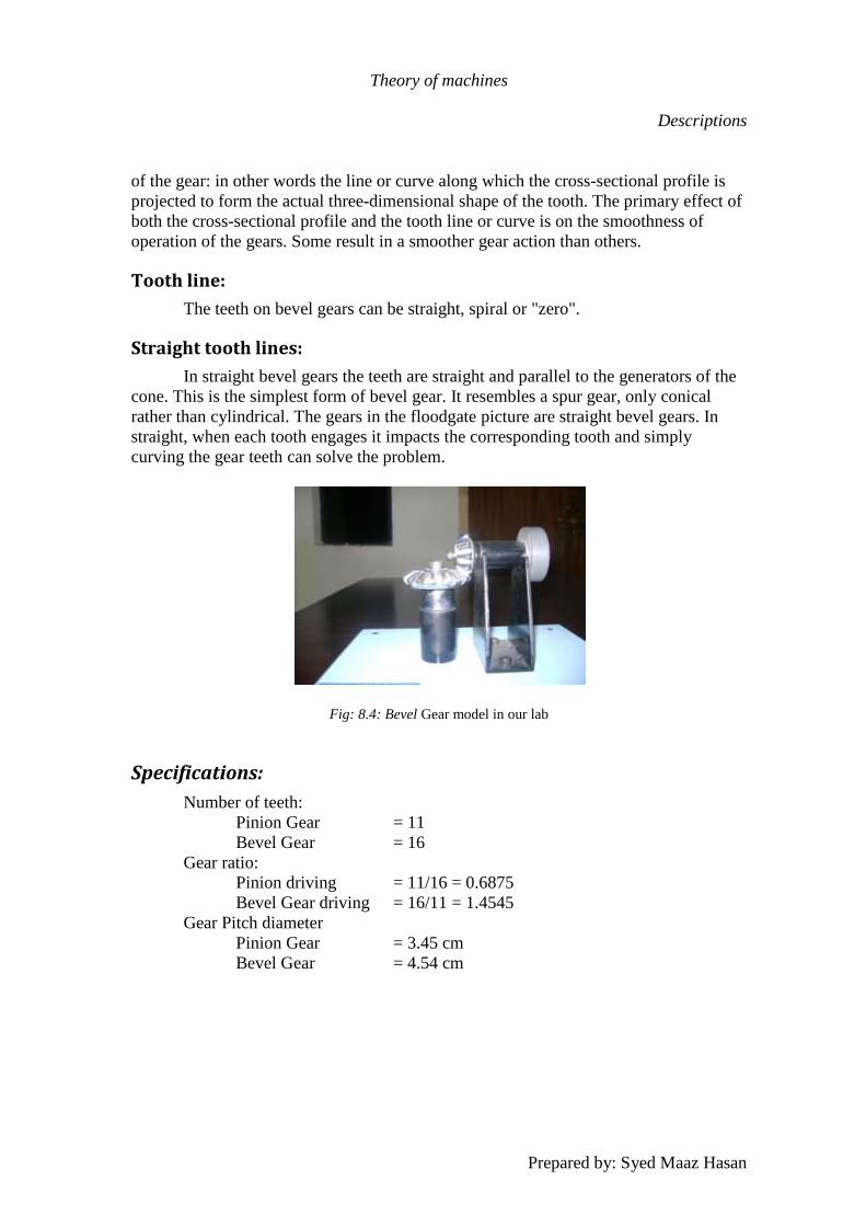
Fig: 8.4: Bevel Gear model in our lab
Specifications:
Number of teeth:
Pinion Gear = 11
Bevel Gear = 16
Gear ratio:
Pinion driving = 11/16 = 0.6875
Bevel Gear driving = 16/11 = 1.4545
Gear Pitch diameter
Pinion Gear = 3.45 cm
Bevel Gear = 4.54 cm
Theory of machines
Descriptions
Prepared by: Syed Maaz Hasan
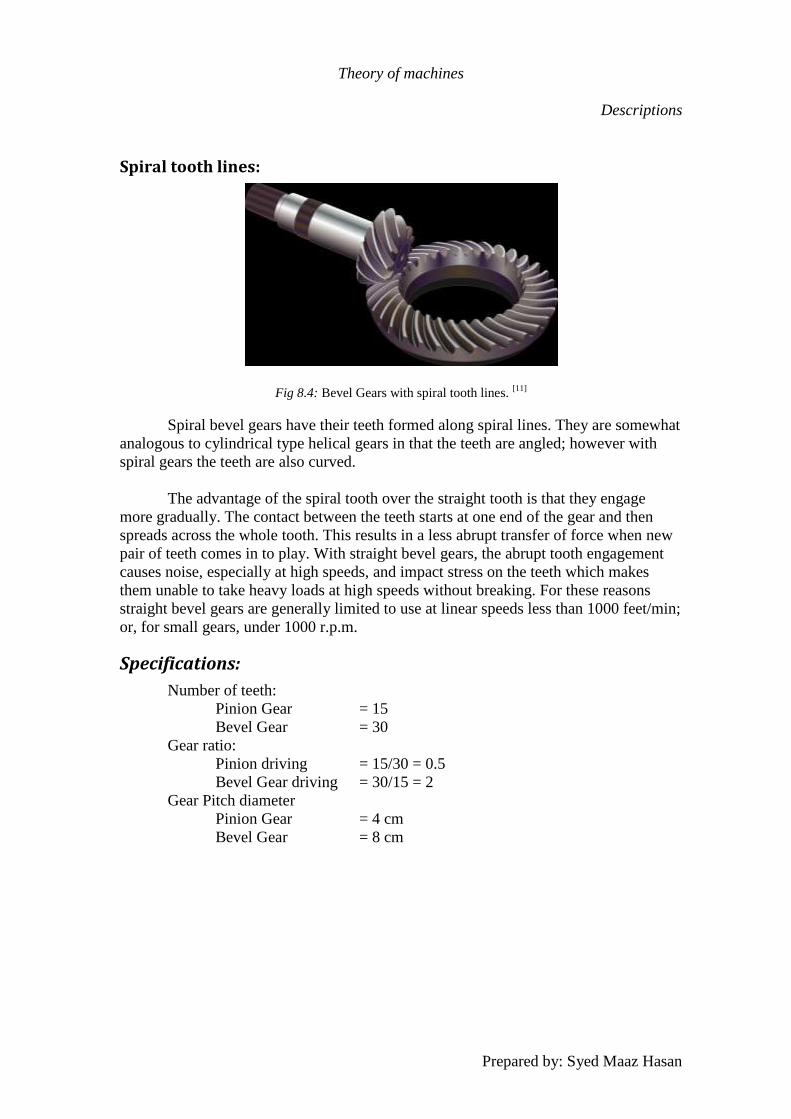
Spiral tooth lines:
Fig 8.4: Bevel Gears with spiral tooth lines. [11]
Spiral bevel gears have their teeth formed along spiral lines. They are somewhat
analogous to cylindrical type helical gears in that the teeth are angled; however with
spiral gears the teeth are also curved.
The advantage of the spiral tooth over the straight tooth is that they engage
more gradually. The contact between the teeth starts at one end of the gear and then
spreads across the whole tooth. This results in a less abrupt transfer of force when new
pair of teeth comes in to play. With straight bevel gears, the abrupt tooth engagement
causes noise, especially at high speeds, and impact stress on the teeth which makes
them unable to take heavy loads at high speeds without breaking. For these reasons
straight bevel gears are generally limited to use at linear speeds less than 1000 feet/min;
or, for small gears, under 1000 r.p.m.
Specifications:
Number of teeth:
Pinion Gear = 15
Bevel Gear = 30
Gear ratio:
Pinion driving = 15/30 = 0.5
Bevel Gear driving = 30/15 = 2
Gear Pitch diameter
Pinion Gear = 4 cm
Bevel Gear = 8 cm
Theory of machines
Descriptions
Prepared by: Syed Maaz Hasan
Zero tooth lines
Zero bevel gears are an intermediate type between straight and spiral bevel
gears. Their teeth are curved, but not angled.
Equipment # 4
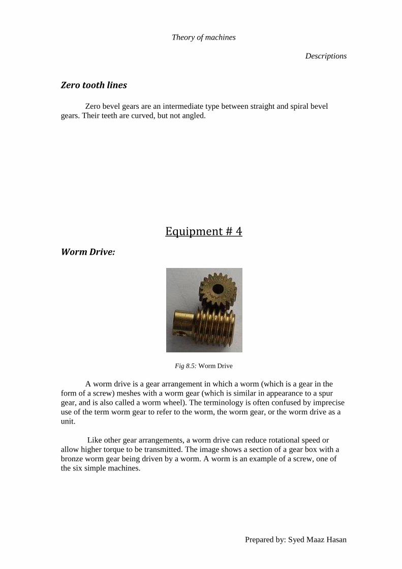
Worm Drive:
Fig 8.5: Worm Drive
A worm drive is a gear arrangement in which a worm (which is a gear in the
form of a screw) meshes with a worm gear (which is similar in appearance to a spur
gear, and is also called a worm wheel). The terminology is often confused by imprecise
use of the term worm gear to refer to the worm, the worm gear, or the worm drive as a
unit.
Like other gear arrangements, a worm drive can reduce rotational speed or
allow higher torque to be transmitted. The image shows a section of a gear box with a
bronze worm gear being driven by a worm. A worm is an example of a screw, one of
the six simple machines.
Theory of machines
Descriptions
Prepared by: Syed Maaz Hasan
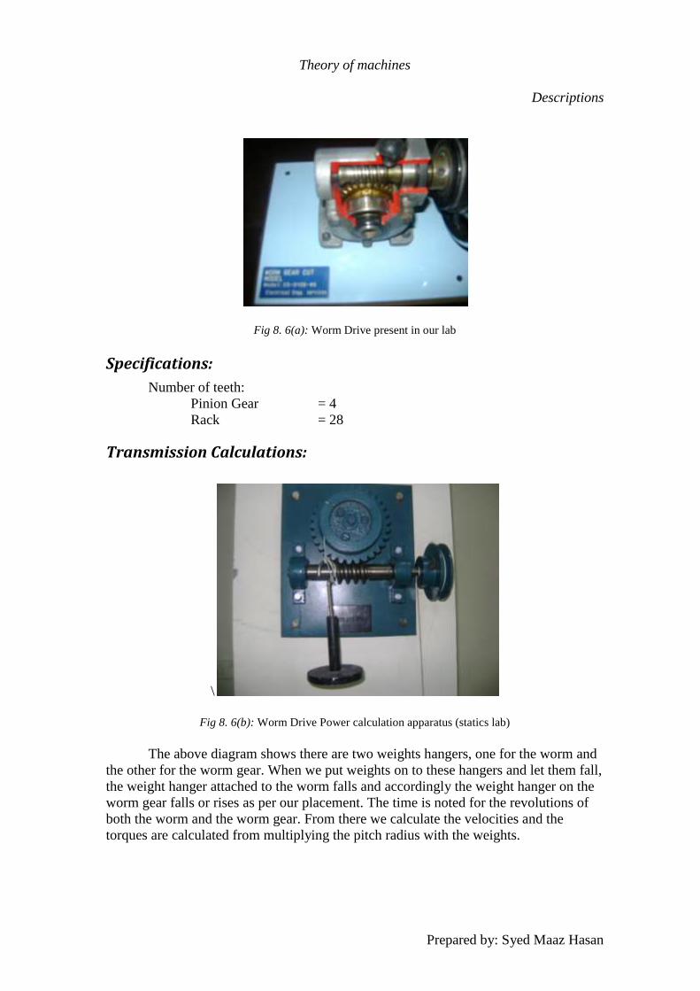
Fig 8. 6(a): Worm Drive present in our lab
Specifications:
Number of teeth:
Pinion Gear = 4
Rack = 28
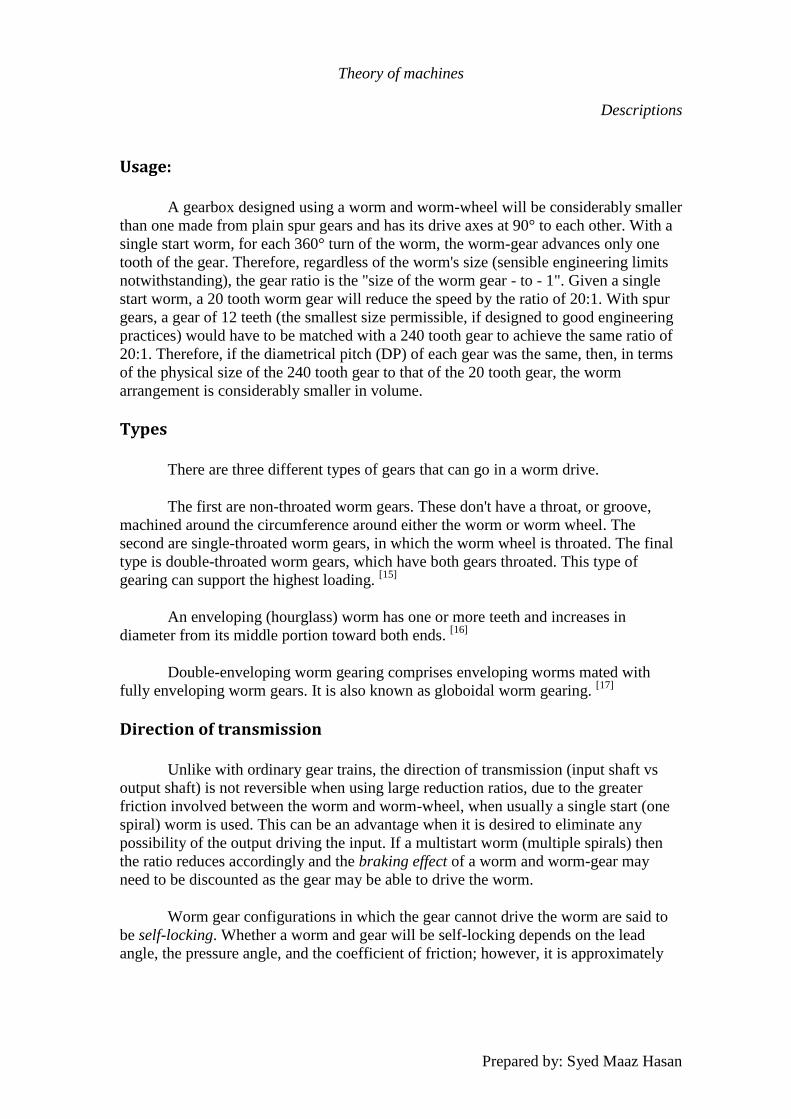
Transmission Calculations:
\
Fig 8. 6(b): Worm Drive Power calculation apparatus (statics lab)
The above diagram shows there are two weights hangers, one for the worm and
the other for the worm gear. When we put weights on to these hangers and let them fall,
the weight hanger attached to the worm falls and accordingly the weight hanger on the
worm gear falls or rises as per our placement. The time is noted for the revolutions of
both the worm and the worm gear. From there we calculate the velocities and the
torques are calculated from multiplying the pitch radius with the weights.
Theory of machines
Descriptions
Prepared by: Syed Maaz Hasan
Usage:
A gearbox designed using a worm and worm-wheel will be considerably smaller
than one made from plain spur gears and has its drive axes at 90° to each other. With a
single start worm, for each 360° turn of the worm, the worm-gear advances only one
tooth of the gear. Therefore, regardless of the worm's size (sensible engineering limits
notwithstanding), the gear ratio is the "size of the worm gear - to - 1". Given a single
start worm, a 20 tooth worm gear will reduce the speed by the ratio of 20:1. With spur
gears, a gear of 12 teeth (the smallest size permissible, if designed to good engineering
practices) would have to be matched with a 240 tooth gear to achieve the same ratio of
20:1. Therefore, if the diametrical pitch (DP) of each gear was the same, then, in terms
of the physical size of the 240 tooth gear to that of the 20 tooth gear, the worm
arrangement is considerably smaller in volume.
Types
There are three different types of gears that can go in a worm drive.
The first are non-throated worm gears. These don't have a throat, or groove,
machined around the circumference around either the worm or worm wheel. The
second are single-throated worm gears, in which the worm wheel is throated. The final
type is double-throated worm gears, which have both gears throated. This type of
gearing can support the highest loading. [15]
An enveloping (hourglass) worm has one or more teeth and increases in
diameter from its middle portion toward both ends. [16]
Double-enveloping worm gearing comprises enveloping worms mated with
fully enveloping worm gears. It is also known as globoidal worm gearing. [17]
Direction of transmission
Unlike with ordinary gear trains, the direction of transmission (input shaft vs
output shaft) is not reversible when using large reduction ratios, due to the greater
friction involved between the worm and worm-wheel, when usually a single start (one
spiral) worm is used. This can be an advantage when it is desired to eliminate any
possibility of the output driving the input. If a multistart worm (multiple spirals) then
the ratio reduces accordingly and the braking effect of a worm and worm-gear may
need to be discounted as the gear may be able to drive the worm.
Worm gear configurations in which the gear cannot drive the worm are said to
be self-locking. Whether a worm and gear will be self-locking depends on the lead
angle, the pressure angle, and the coefficient of friction; however, it is approximately
Theory of machines
Descriptions
Prepared by: Syed Maaz Hasan
correct to say that a worm and gear will be self-locking if the tangent of the lead angle
is less than the coefficient of friction.
Applications:
There are numerous applications of the worm drives out of which some are
discussed below:
A worm-drive controlling a gate is a common example. The position of the gate
cannot change after being set
In early 20th century automobiles prior to the introduction of power steering,
the effect of a flat or blowout on one of the front wheels will tend to pull the steering
mechanism toward the side with the flat tire. The employment of a worm screw reduced
this effect. Further development of the worm drive employs recirculation ball bearings
to reduce frictional forces, allowing some of the steering force to be felt in the wheel as
an aid to vehicle control and greatly reducing wear, which leads to difficulties in
steering precisely.
Worm drives are a compact means of substantially decreasing speed and
increasing torque. Small electric motors are generally high-speed and low-torque; the
addition of a worm drive increases the range of applications that it may be suitable for,
especially when the worm drive's compactness is considered.
Worm drives are used in presses, in rolling mills, in conveying engineering, in
mining industry machines, and on rudders. In addition, milling heads and rotary tables
are positioned using high-precision duplex worm drives with adjustable backlash.
Worm gears are used on many lift- (in US English known as elevator) and escalator-
drive applications due to their compact size and the non-reversibility of the gear.
Truck final drive of the 1930s
Worm drives have been used in a few automotive rear-axle final drives
(although not the differential itself at this time). They took advantage of the location of
the gear being at either the very top or very bottom of the differential crown wheel. In
the 1910s they were common on trucks; to gain the most clearance on muddy roads the
worm gear was placed on top. In the 1920s the Stutz firm used them on its cars; to have
a lower floor than its competitors, the gear was located on the bottom. An example
from around 1960 was the Peugeot 404. The worm gear carries the differential gearing,
which protects the vehicle against rollback. This ability has largely fallen from favour
due to the higher-than-necessary reduction ratios.
A more recent exception to this is the Torsen differential, which uses worms
and planetary worm gears in place of the bevel gearing of conventional open
differentials. Torsen differentials are most prominently featured in the HMMWV and
Theory of machines
Descriptions
Prepared by: Syed Maaz Hasan
some commercial Hummer vehicles and as a center differential in some all wheel drive
systems, such as Audi's quattro. Very heavy trucks, such as those used to carry
aggregates, often use a worm gear differential for strength. The worm drive is not as
efficient as a hypoid gear, and such trucks invariably have a very large differential
housing, with a correspondingly large volume of gear oil, to absorb and dissipate the
heat created.
Worm drives are used as the tuning mechanism for many musical instruments,
including guitars, double-basses, mandolins and bouzoukis, although not banjos, which
use planetary gears or friction pegs. A worm drive tuning device is called a machine
head.
Plastic worm drives are often used on small battery-operated electric motors, to
provide an output with a lower angular velocity (fewer revolutions per minute) than that
of the motor, which operates best at a fairly high speed. This motor-worm-gear drive
system is often used in toys and other small electrical devices.
A worm drive is used on jubilee-type hose clamps or jubilee clamps; the
tightening screw has a worm thread which engages with the slots on the clamp band.
Occasionally a worm gear is designed to be run in reverse, resulting in the
output shaft turning much faster than the input. Examples of this may be seen in some
hand-cranked centrifuges or the wind governor in a musical box. [13]
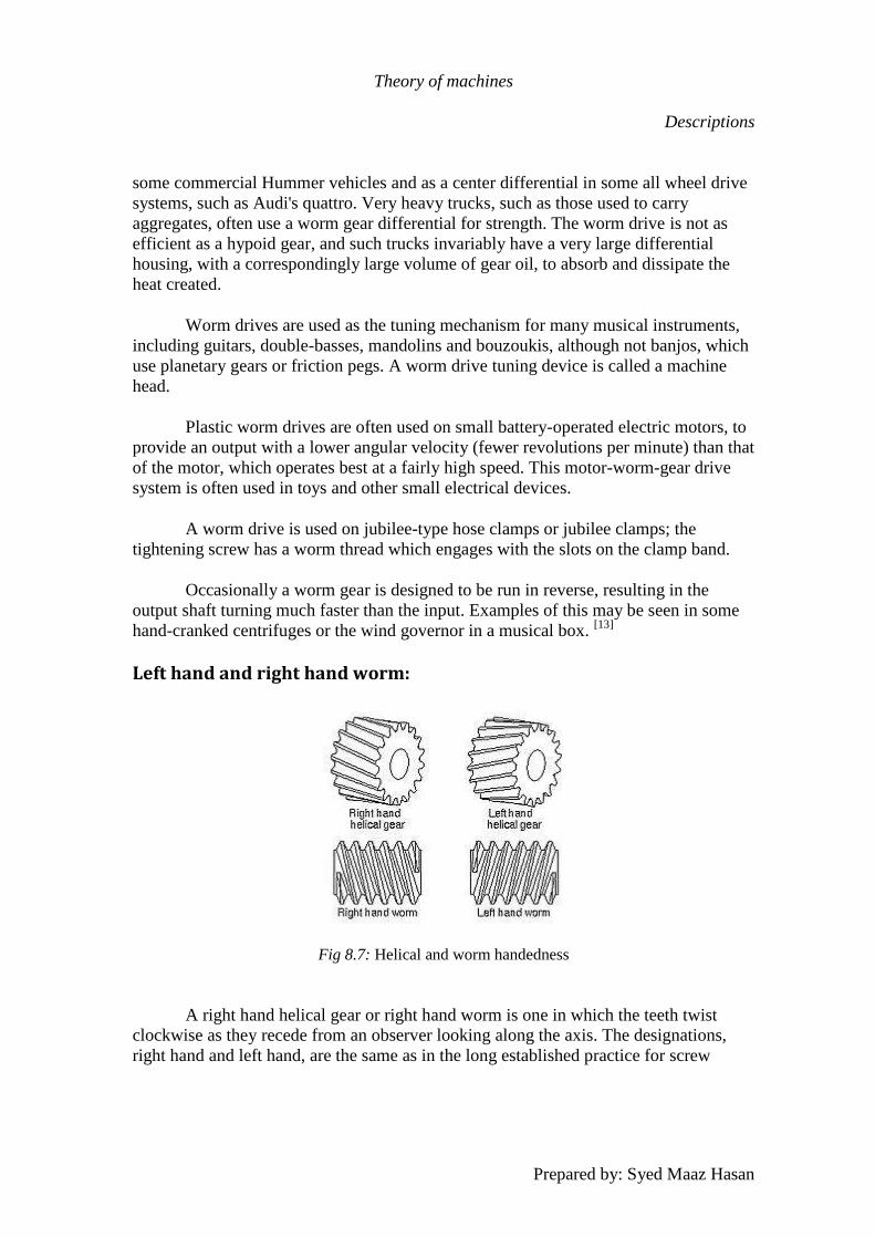
Left hand and right hand worm:
Fig 8.7: Helical and worm handedness
A right hand helical gear or right hand worm is one in which the teeth twist
clockwise as they recede from an observer looking along the axis. The designations,
right hand and left hand, are the same as in the long established practice for screw
Theory of machines
Descriptions
Prepared by: Syed Maaz Hasan
threads, both external and internal. Two external helical gears operating on parallel
axes must be of opposite hand. An internal helical gear and its pinion must be of the
same hand.
A left hand helical gear or left hand worm is one in which the teeth twist
counterclockwise as they recede from an observer looking along the axis. [18]

Theory of machines
Descriptions
Prepared by: Syed Maaz Hasan
Equipment # 5
Rack and Pinion:
Rack and pinion was first invented just as soon as the wheel was invented. In
fact, the wheel is the first and earliest example of rack and pinion machine design. The
design is based upon making a round cog or wheel move on a linier surface, thereby
generating either movement or some other sort of mechanical advantage in the process.
Since being the most ancient, the wheel is also the most convenient and somewhat more
extensive in terms of energy too. Due to the apparent friction, you would already have
guessed just how much of the power being input gives in terms of output, a lot of the
force applied to the mechanism is burned up in overcoming friction, to be more precise
somewhat around 80% of the overall force is burned to overcome one. The concept of
rack and pinion, as old as it seems is still in use these days.
The best known mechanism yet to convert a rotary motion into a linier one, the
rack and pinion can only work with certain levels of friction. Too high a friction and the
mechanism will be subject to wear more than usual and will require more force to
operate. The most adverse disadvantage of rack and pinion would also be due to the
inherent friction, the same force that actually makes things work in the mechanism. Due
to the friction, it is under a constant wear, possibly needing replacement after a certain
time. The mechanism is no longer the way it was in the old days though, to prevent
backlash and to minimize any possible friction, the later versions were introduced with
teeth to match in both products. Plenty of other changes have been made to enhance the
mechanical advantage of the mechanism. If you looked hard enough, even you would
be able to see the difference between the historic rack and pinion and the equivalent
mechanism in common use these days. Not only are gears and jaws added, but for
certain circumstances, the mechanism are specifically altered to provide the best
possible mechanical advantage. With latest techniques, not only has the mechanical
advantage of the rack and pinion mechanism has been increased manifold but with the
use of things like jaws and gears and ball bearings, even the friction has been decreased
to a considerable ratio not only ensuring a longer lifetime but also better outputs per
input force.
The rack and pinion present in our lab is a helical rack and pinion. The
advantages of the helical rack and pinion over the conventional rack and pinion are the
same which a helical gear holds over the conventional spur gear.
Theory of machines
Descriptions
Prepared by: Syed Maaz Hasan
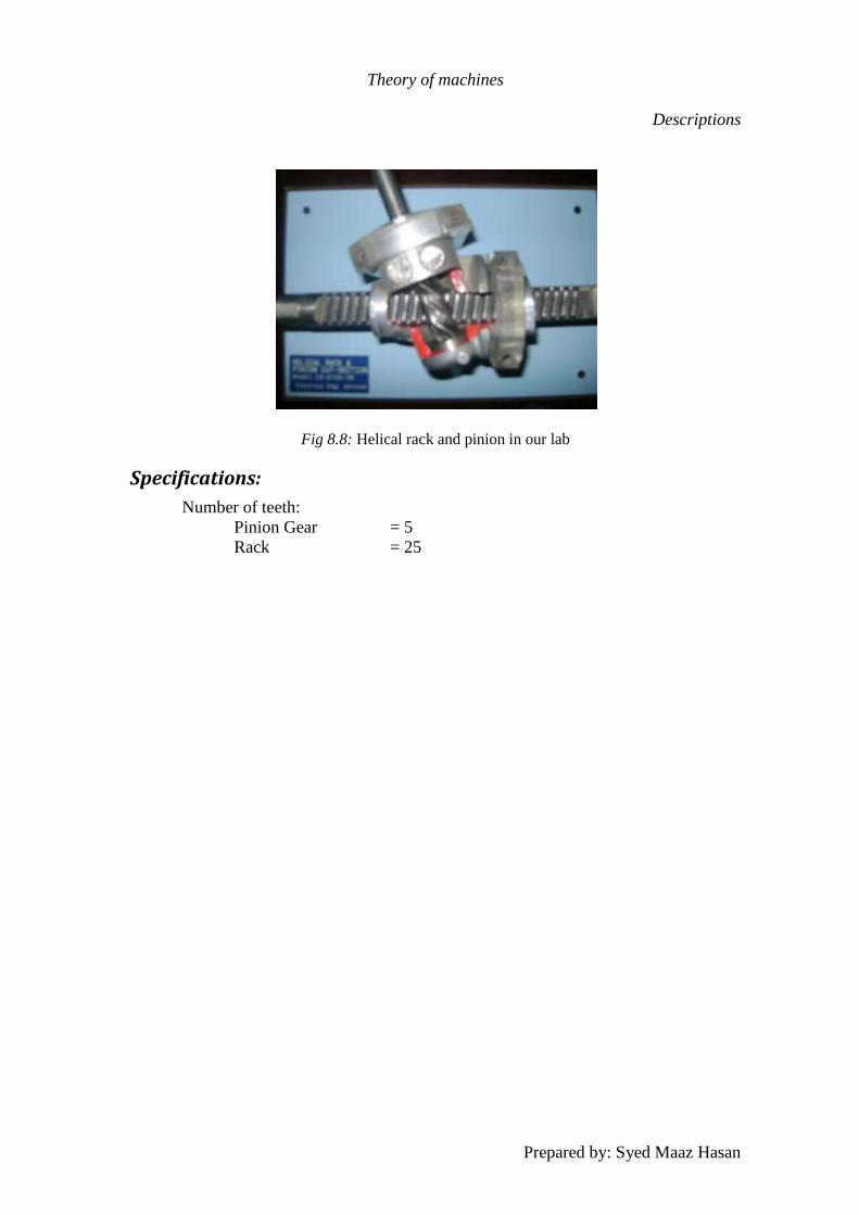
Fig 8.8: Helical rack and pinion in our lab
Specifications:
Number of teeth:
Pinion Gear = 5
Rack = 25
Theory of machines
Descriptions
Prepared by: Syed Maaz Hasan
Equipment # 6
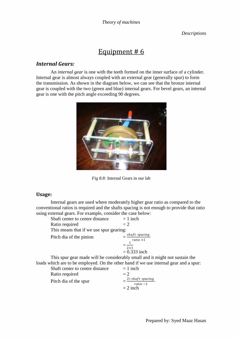
Internal Gears:
An internal gear is one with the teeth formed on the inner surface of a cylinder.
Internal gear is almost always coupled with an external gear (generally spur) to form
the transmission. As shown in the diagram below, we can see that the bronze internal
gear is coupled with the two (green and blue) internal gears. For bevel gears, an internal
gear is one with the pitch angle exceeding 90 degrees.
Fig 8.8: Internal Gears in our lab
Usage:
Internal gears are used where moderately higher gear ratio as compared to the
conventional ratios is required and the shafts spacing is not enough to provide that ratio
using external gears. For example, consider the case below:
Shaft center to centre distance = 1 inch
Ratio required = 2
This means that if we use spur gearing:
Pitch dia of the pinion = 𝑠𝑎𝑓𝑡 𝑠𝑝𝑎𝑐𝑖𝑛𝑔
𝑟𝑎𝑡𝑖𝑜 +1
= 1
2+1
= 0.333 inch
This spur gear made will be considerably small and it might not sustain the
loads which are to be employed. On the other hand if we use internal gear and a spur:
Shaft center to centre distance = 1 inch
Ratio required = 2
Pitch dia of the spur = 2∗ 𝑠𝑎𝑓𝑡 𝑠𝑝𝑎𝑐𝑖𝑛𝑔
𝑟𝑎𝑡𝑖𝑜 −1
= 2 inch
Theory of machines
Descriptions
Prepared by: Syed Maaz Hasan
Comparing both diameters we can see that internal gears will have larger size
and thus, should hold larger toques easily.
Another usage of the internal gears is that they do not cause direction reversal,
therefore whenever transmission is required in parallel shafts without the shaft
rotational direction reversal, internal gears are used.
Theory of machines
Descriptions
Prepared by: Syed Maaz Hasan
Equipment # 7
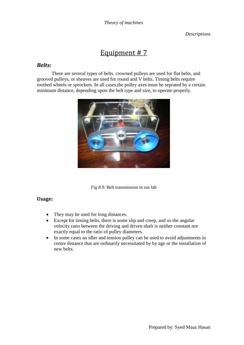
Belts:
There are several types of belts. crowned pulleys are used for flat belts, and
grooved pulleys, or sheaves are used for round and V belts. Timing belts require
toothed wheels or sprockets. In all cases,the pulley axes must be seprated by a certain
minimum distance, depending upon the belt type and size, to operate properly.
Fig 8.9: Belt transmission in our lab
Usage:
They may be used for long distances.
Except for timing belts, there is some slip and creep, and so the angular
velocity ratio between the driving and driven shaft is neither constant nor
exactly equal to the ratio of pulley diameters.
In some cases an idler and tension pulley can be used to avoid adjustments in
centre distance that are ordinarily necessitated by by age or the installation of
new belts.
Theory of machines
Descriptions
Prepared by: Syed Maaz Hasan
Equipment # 8
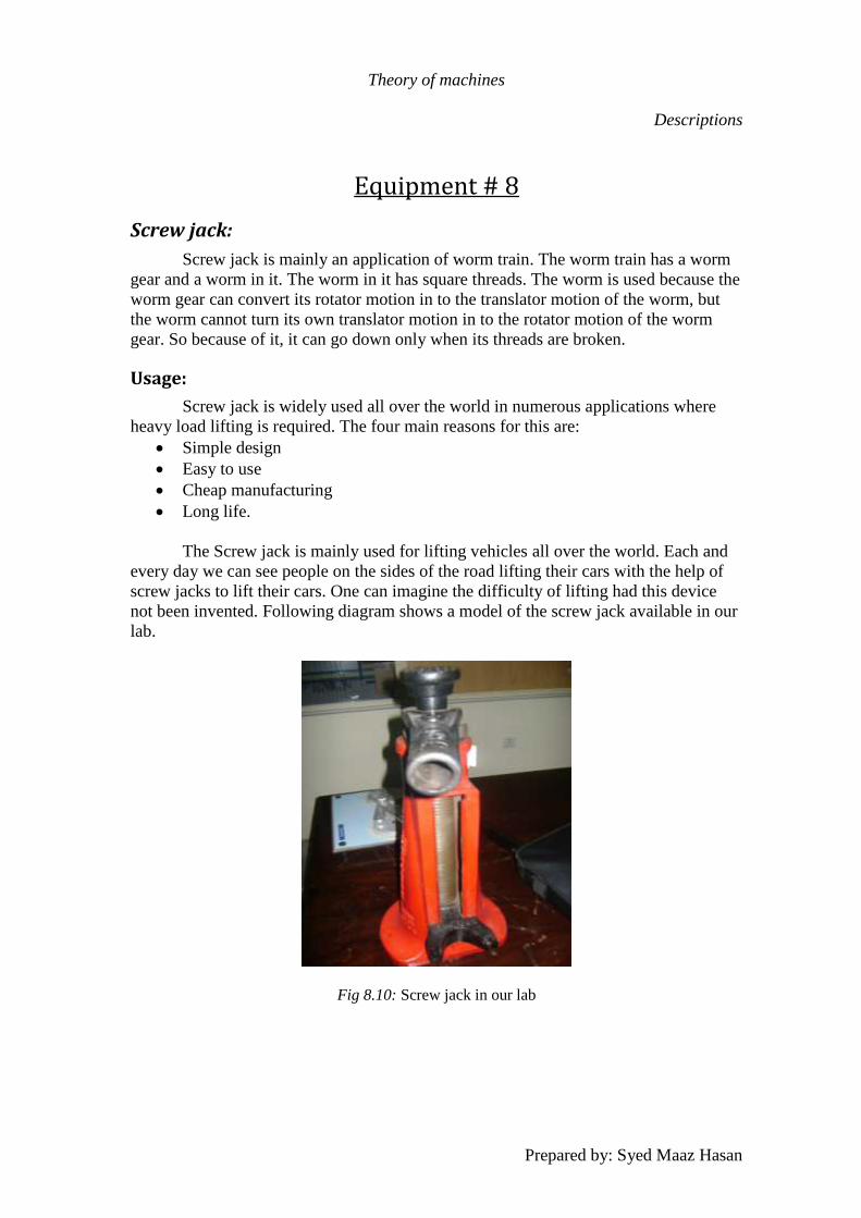
Screw jack:
Screw jack is mainly an application of worm train. The worm train has a worm
gear and a worm in it. The worm in it has square threads. The worm is used because the
worm gear can convert its rotator motion in to the translator motion of the worm, but
the worm cannot turn its own translator motion in to the rotator motion of the worm
gear. So because of it, it can go down only when its threads are broken.
Usage:
Screw jack is widely used all over the world in numerous applications where
heavy load lifting is required. The four main reasons for this are:
Simple design
Easy to use
Cheap manufacturing
Long life.
The Screw jack is mainly used for lifting vehicles all over the world. Each and
every day we can see people on the sides of the road lifting their cars with the help of
screw jacks to lift their cars. One can imagine the difficulty of lifting had this device
not been invented. Following diagram shows a model of the screw jack available in our
lab.
Fig 8.10: Screw jack in our lab
Theory of machines
Descriptions
Prepared by: Syed Maaz Hasan
Equipment # 9
Differential :
A differential is a device, usually but not necessarily employing gears, capable
of transmitting torque and rotation through three shafts, almost always used in one of
two ways: in one way, it receives one input and provides two outputs—this is found in
most automobiles—and in the other way, it combines two inputs to create an output that
is the sum, difference, or average, of the inputs.
In automobiles and other wheeled vehicles, the differential allows each of the
driving road wheels to rotate at different speeds, while for most vehicles supplying
equal torque to each of them.
Working:
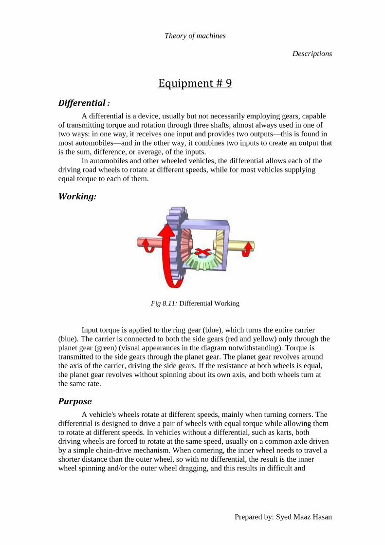
Fig 8.11: Differential Working
Input torque is applied to the ring gear (blue), which turns the entire carrier
(blue). The carrier is connected to both the side gears (red and yellow) only through the
planet gear (green) (visual appearances in the diagram notwithstanding). Torque is
transmitted to the side gears through the planet gear. The planet gear revolves around
the axis of the carrier, driving the side gears. If the resistance at both wheels is equal,
the planet gear revolves without spinning about its own axis, and both wheels turn at
the same rate.
Purpose
A vehicle's wheels rotate at different speeds, mainly when turning corners. The
differential is designed to drive a pair of wheels with equal torque while allowing them
to rotate at different speeds. In vehicles without a differential, such as karts, both
driving wheels are forced to rotate at the same speed, usually on a common axle driven
by a simple chain-drive mechanism. When cornering, the inner wheel needs to travel a
shorter distance than the outer wheel, so with no differential, the result is the inner
wheel spinning and/or the outer wheel dragging, and this results in difficult and
Theory of machines
Descriptions
Prepared by: Syed Maaz Hasan
unpredictable handling, damage to tires and roads, and strain on (or possible failure of)
the entire drive train.
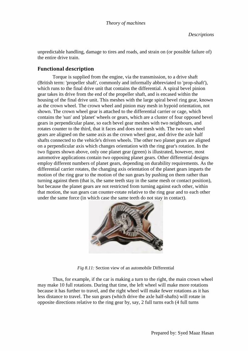
Functional description
Torque is supplied from the engine, via the transmission, to a drive shaft
(British term: 'propeller shaft', commonly and informally abbreviated to 'prop-shaft'),
which runs to the final drive unit that contains the differential. A spiral bevel pinion
gear takes its drive from the end of the propeller shaft, and is encased within the
housing of the final drive unit. This meshes with the large spiral bevel ring gear, known
as the crown wheel. The crown wheel and pinion may mesh in hypoid orientation, not
shown. The crown wheel gear is attached to the differential carrier or cage, which
contains the 'sun' and 'planet' wheels or gears, which are a cluster of four opposed bevel
gears in perpendicular plane, so each bevel gear meshes with two neighbours, and
rotates counter to the third, that it faces and does not mesh with. The two sun wheel
gears are aligned on the same axis as the crown wheel gear, and drive the axle half
shafts connected to the vehicle's driven wheels. The other two planet gears are aligned
on a perpendicular axis which changes orientation with the ring gear's rotation. In the
two figures shown above, only one planet gear (green) is illustrated, however, most
automotive applications contain two opposing planet gears. Other differential designs
employ different numbers of planet gears, depending on durability requirements. As the
differential carrier rotates, the changing axis orientation of the planet gears imparts the
motion of the ring gear to the motion of the sun gears by pushing on them rather than
turning against them (that is, the same teeth stay in the same mesh or contact position),
but because the planet gears are not restricted from turning against each other, within
that motion, the sun gears can counter-rotate relative to the ring gear and to each other
under the same force (in which case the same teeth do not stay in contact).
Fig 8.11: Section view of an automobile Differential
Thus, for example, if the car is making a turn to the right, the main crown wheel
may make 10 full rotations. During that time, the left wheel will make more rotations
because it has further to travel, and the right wheel will make fewer rotations as it has
less distance to travel. The sun gears (which drive the axle half-shafts) will rotate in
opposite directions relative to the ring gear by, say, 2 full turns each (4 full turns
Theory of machines
Descriptions
Prepared by: Syed Maaz Hasan
relative to each other), resulting in the left wheel making 12 rotations, and the right
wheel making 8 rotations.
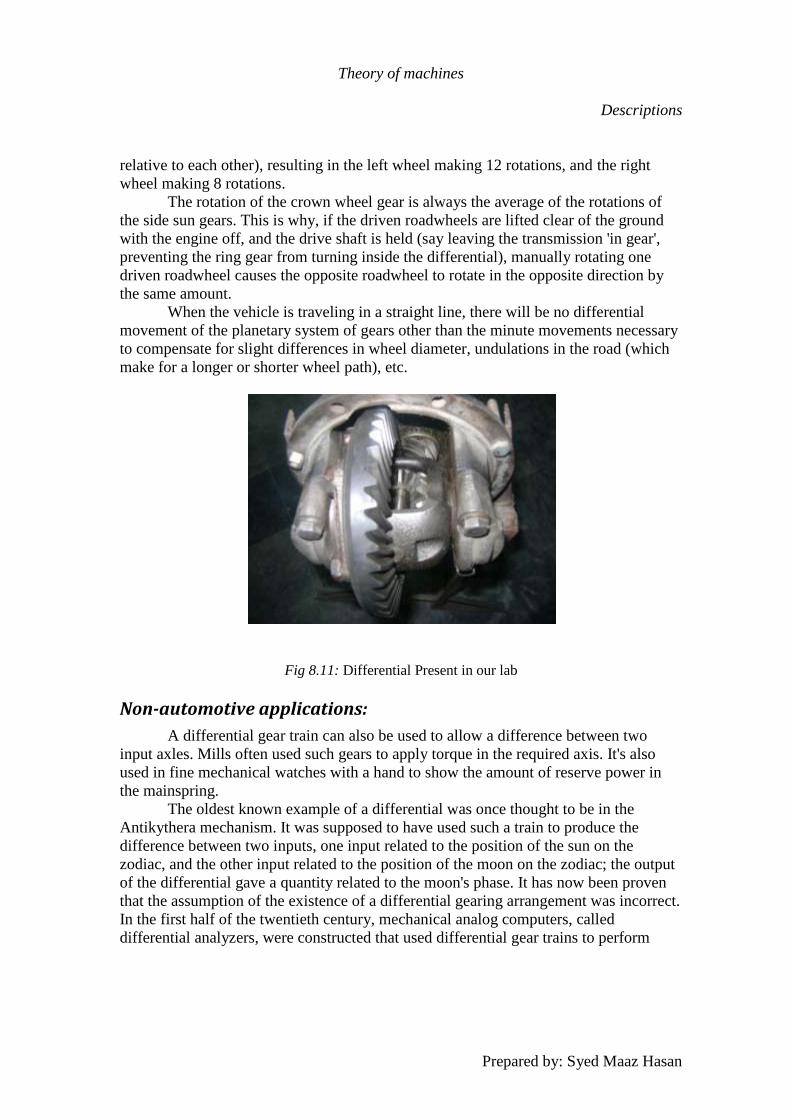
The rotation of the crown wheel gear is always the average of the rotations of
the side sun gears. This is why, if the driven roadwheels are lifted clear of the ground
with the engine off, and the drive shaft is held (say leaving the transmission 'in gear',
preventing the ring gear from turning inside the differential), manually rotating one
driven roadwheel causes the opposite roadwheel to rotate in the opposite direction by
the same amount.
When the vehicle is traveling in a straight line, there will be no differential
movement of the planetary system of gears other than the minute movements necessary
to compensate for slight differences in wheel diameter, undulations in the road (which
make for a longer or shorter wheel path), etc.
Fig 8.11: Differential Present in our lab
Non-automotive applications:
A differential gear train can also be used to allow a difference between two
input axles. Mills often used such gears to apply torque in the required axis. It's also
used in fine mechanical watches with a hand to show the amount of reserve power in
the mainspring.
The oldest known example of a differential was once thought to be in the
Antikythera mechanism. It was supposed to have used such a train to produce the
difference between two inputs, one input related to the position of the sun on the
zodiac, and the other input related to the position of the moon on the zodiac; the output
of the differential gave a quantity related to the moon's phase. It has now been proven
that the assumption of the existence of a differential gearing arrangement was incorrect.
In the first half of the twentieth century, mechanical analog computers, called
differential analyzers, were constructed that used differential gear trains to perform
Theory of machines
Descriptions
Prepared by: Syed Maaz Hasan
addition and subtraction. The U.S. Navy Mk.1 gun fire control computer used about
160 differentials of the bevel-gear type.
Differentials, usually flat but also spherical, are used in wristwatches to allow
the power reserve to be indicated. Power from the mainspring is split via the differential
to the time indications and the power reserve indicator. Differentials are also used in
watchmaking to link two separate regulating systems with the aim of averaging out
errors. Greubel Forsey use a spherical differential to link two double tourbillon systems
in their Quadruple Differential Tourbillon.[11]
Spur Gear Lifting Apparatus:
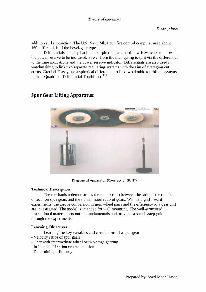
Diagram of Apparatus (Courtesy of GUNT)
Technical Description:
The mechanism demonstrates the relationship between the ratio of the number
of teeth on spur gears and the transmission ratio of gears. With straightforward
experiments, the torque conversion in gear wheel pairs and the efficiency of a gear unit
are investigated. The model is intended for wall mounting. The well-structured
instructional material sets out the fundamentals and provides a step-bystep guide
through the experiments.
Learning Objectives:
Learning the key variables and correlations of a spur gear
- Velocity ratios of spur gears
- Gear with intermediate wheel or two-stage gearing
- Influence of friction on transmission
- Determining efficiency

Theory of machines
Descriptions
Prepared by: Syed Maaz Hasan
Specification:
[1] Demonstration and student experimental unit on
set-up and principle of toothed gearing mechanisms
[2] 4 galvanised steel gear wheels
[3] 2 anodised aluminium cable pulleys
[4] 2 sets of weights
[5] Ball bearing-mounted gear wheels and pulleys
[6] Anodised aluminium base plate
Technical Data:
4 gear wheels
- 2x D=126mm, 84 teeth
- 2x D=42mm, 28 teeth
- modulus: m=2mm
Driving pulley radius: 35mm
Set of weights
- 2x 1N suspended
- 2x 0,25N
- 1x 0,5N
- 2x 1N
- 2x 2N
- 2x 2,5N
Base plate
- lxwxh: 350x150x10mm
Dimensions and Weight:
L x w x h: 350x70x150mm
Weight: approx. 5kg
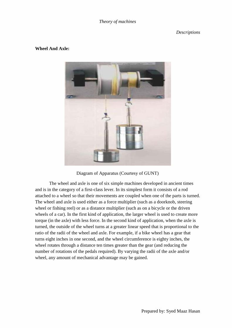
Theory of machines
Descriptions
Prepared by: Syed Maaz Hasan
Wheel And Axle:
Diagram of Apparatus (Courtesy of GUNT)
The wheel and axle is one of six simple machines developed in ancient times
and is in the category of a first-class lever. In its simplest form it consists of a rod
attached to a wheel so that their movements are coupled when one of the parts is turned.
The wheel and axle is used either as a force multiplier (such as a doorknob, steering
wheel or fishing reel) or as a distance multiplier (such as on a bicycle or the driven
wheels of a car). In the first kind of application, the larger wheel is used to create more
torque (in the axle) with less force. In the second kind of application, when the axle is
turned, the outside of the wheel turns at a greater linear speed that is proportional to the
ratio of the radii of the wheel and axle. For example, if a bike wheel has a gear that
turns eight inches in one second, and the wheel circumference is eighty inches, the
wheel rotates through a distance ten times greater than the gear (and reducing the
number of rotations of the pedals required). By varying the radii of the axle and/or
wheel, any amount of mechanical advantage may be gained.
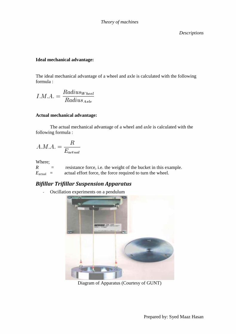
Theory of machines
Descriptions
Prepared by: Syed Maaz Hasan
Ideal mechanical advantage:
The ideal mechanical advantage of a wheel and axle is calculated with the following
formula :
Actual mechanical advantage:
The actual mechanical advantage of a wheel and axle is calculated with the
following formula :
Where;
R = resistance force, i.e. the weight of the bucket in this example.
Eactual = actual effort force, the force required to turn the wheel.
Bifillar Trifillar Suspension Apparatus
- Oscillation experiments on a pendulum
Diagram of Apparatus (Courtesy of GUNT)
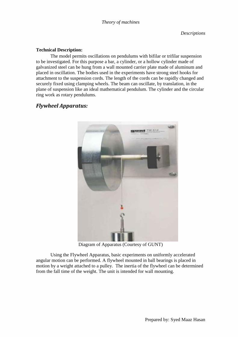
Theory of machines
Descriptions
Prepared by: Syed Maaz Hasan
Technical Description:
The model permits oscillations on pendulums with bifilar or trifilar suspension
to be investigated. For this purpose a bar, a cylinder, or a hollow cylinder made of
galvanized steel can be hung from a wall mounted carrier plate made of aluminum and
placed in oscillation. The bodies used in the experiments have strong steel hooks for
attachment to the suspension cords. The length of the cords can be rapidly changed and
securely fixed using clamping wheels. The beam can oscillate, by translation, in the
plane of suspension like an ideal mathematical pendulum. The cylinder and the circular
ring work as rotary pendulums.
Flywheel Apparatus:
Diagram of Apparatus (Courtesy of GUNT)
Using the Flywheel Apparatus, basic experiments on uniformly accelerated
angular motion can be performed. A flywheel mounted in ball bearings is placed in
motion by a weight attached to a pulley. The inertia of the flywheel can be determined
from the fall time of the weight. The unit is intended for wall mounting.
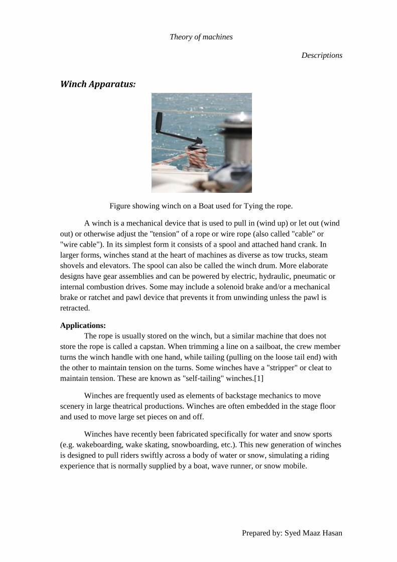
Theory of machines
Descriptions
Prepared by: Syed Maaz Hasan
Winch Apparatus:
Figure showing winch on a Boat used for Tying the rope.
A winch is a mechanical device that is used to pull in (wind up) or let out (wind
out) or otherwise adjust the "tension" of a rope or wire rope (also called "cable" or
"wire cable"). In its simplest form it consists of a spool and attached hand crank. In
larger forms, winches stand at the heart of machines as diverse as tow trucks, steam
shovels and elevators. The spool can also be called the winch drum. More elaborate
designs have gear assemblies and can be powered by electric, hydraulic, pneumatic or
internal combustion drives. Some may include a solenoid brake and/or a mechanical
brake or ratchet and pawl device that prevents it from unwinding unless the pawl is
retracted.
Applications:
The rope is usually stored on the winch, but a similar machine that does not
store the rope is called a capstan. When trimming a line on a sailboat, the crew member
turns the winch handle with one hand, while tailing (pulling on the loose tail end) with
the other to maintain tension on the turns. Some winches have a "stripper" or cleat to
maintain tension. These are known as "self-tailing" winches.[1]
Winches are frequently used as elements of backstage mechanics to move
scenery in large theatrical productions. Winches are often embedded in the stage floor
and used to move large set pieces on and off.
Winches have recently been fabricated specifically for water and snow sports
(e.g. wakeboarding, wake skating, snowboarding, etc.). This new generation of winches
is designed to pull riders swiftly across a body of water or snow, simulating a riding
experience that is normally supplied by a boat, wave runner, or snow mobile.
Theory of machines
Descriptions
Prepared by: Syed Maaz Hasan
References:
1. Design of machinery, Second Edition, p 68.
2. Design of machinery, Second Edition, p 121
3. Design of machinery, Second Edition, p 452
4. Design of machinery, Second Edition, p 829
5. Design of machinery, Second Edition, p 800
6. Design of machinery, Second Edition, p 746
7. Design of machinery, Second Edition, p 829
8. Design of machinery, Second Edition, p 635
9. Design of machinery, Second Edition, p 882
10. Howstuffworks "Transmission Basics"
11. Wikipedia
12. Doughtie and Vallance give the following information on helical gear speeds:
"Pitch-line speeds of 4,000 to 7,000 fpm [20 to 36 m/s] are common with
automobile and turbine gears, and speeds of 12,000 fpm [61 m/s] have been
successfully used." -- p.281.
13. Helical gears,
http://www.roymech.co.uk/Useful_Tables/Drive/Hellical_Gears.html.
14. Doughty and Vallance, Design of Machine Members.
15. "Worm Gears". http://www.gearshub.com/worm-gears.html. Retrieved 2009-
05-01.
16. Gear Nomenclature, Definition of Terms with Symbols. American Gear
Manufacturers Association. p. 3. ANSI/AGMA 1012-G05. ISBN 1-55589-846-
7. OCLC 65562739
17. Gear Nomenclature, Definition of Terms with Symbols. American Gear
Manufacturers Association. p. 4. ANSI/AGMA 1012-G05. ISBN 1-55589-846-
7. OCLC 65562739.
Theory of machines
Descriptions
Prepared by: Syed Maaz Hasan
18. Gear Nomenclature, Definition of Terms with Symbols. American Gear
Manufacturers Association. ANSI/AGMA 1012-G05. ISBN 1-55589-846-7.
OCLC 65562739
19. http://www.rackandpinion.org/