Mechanism and Machine Theory - Technion
12
Robotic swimmer/pump based on an optimal wave generating mechanism Eyal Setter, Izhak Bucher ⁎ Faculty of Mechanical Engineering, Technion-Israel Inst. of Technology, Haifa 32000, Israel article info abstract Article history: Received 28 August 2012 Received in revised form 21 July 2013 Accepted 23 July 2013 Available online xxxx This paper describes a unique mechanism that generates longitudinally traveling waves as a means for fluid manipulation i.e., self-propulsion or pumping in low Reynolds number environments. Possible applications include small-scale micro-robotic swimmers or large-scale pumps for highly viscous fluids. The proposed mechanism generates axi-symmetrical transverse traveling waves along a cylindrical elastic membrane, and it is designed so that the required internal actuation torque on the input shaft is zero in the absence of friction. The paper also demonstrates that torque oscillations can be completely eliminated, even when motional friction exists and only a small constant torque is required to overcome friction. Since torque oscillations are associated with alternating stresses and fatigue, the proposed design increases the service life of the device and, moreover, considerably reduces the power consumption. It is demonstrated analytically and numerically that these properties are achieved by choosing a specific spatial rotational phase between successive cams, and by choosing a certain ratio between the number of wavelengths and cams along the device. A realistic macro-scale device that can be tuned to fulfil the optimal conditions is also described. © 2013 Elsevier Ltd. All rights reserved. Keywords: Cam-based mechanism Traveling waves Torque minimization Fluid manipulation Low Reynolds number environment 1. Introduction Traveling mechanical waves are a physical phenomenon widely used in engineering and robotics. Vibration-induced traveling waves [1] are mainly used as a means for conveying objects, as in rotary or linear ultrasonic motors [2,3] or are coupled with acoustic levitation to reduce friction [4]. Low frequency traveling waves are encountered in self-propelled robots, such as snake-like robots moving on solid surfaces [5,6] and snail-like robots moving on a thin slime film [7]. Traveling waves as a means of self-propulsion in liquids are encountered in a large variety of Reynolds number environments. In high Reynolds number environments where inertia dominates viscous forces, waving fins are employed to propel biomimetic fish-like robots [8]. Under low Reynolds number conditions, as in small scales or highly viscous environments, the dynamics is governed mainly by viscous effects. Therefore, any transport mechanism must rely on non-inertial and non-time reversible trajectories [9]. These conditions are fully satisfied by traveling mechanical waves, one of the common motility mechanisms for unicellular creatures [10,11]. Traveling waves are also utilized in micro-robotic artificial swimmers [12], and more recently in micro pumps as well [13,14]. The growing interest in micro-swimmers stems from their potential therapeutic capabilities, such as targeted drug delivery and non-invasive micro surgery and diagnosis [15]. Vibration-induced traveling waves [16] are energetically advantageous when the device exploits natural resonance phenomena [17]. Yet, in the present case, resonance cannot be utilized due to incompatible time-scales and the relatively large required amplitudes [18], making it impractical and highly inefficient. Moreover, the hydrodynamic efficiencies of low Reynolds fluid manipulators are rather low [19]. Therefore, especially in small-scale autonomous mobile applications where weight and volume constraints are critical, an efficient propulsion mechanism is required. Mechanism and Machine Theory 70 (2013) 266–277 ⁎ Corresponding author. Tel.: +972 48293153; fax: +972 48295711. E-mail address: [email protected] (I. Bucher). 0094-114X/$ – see front matter © 2013 Elsevier Ltd. All rights reserved. http://dx.doi.org/10.1016/j.mechmachtheory.2013.07.017 Contents lists available at ScienceDirect Mechanism and Machine Theory journal homepage: www.elsevier.com/locate/mechmt
Transcript of Mechanism and Machine Theory - Technion

Mechanism and Machine Theory 70 (2013) 266–277
Contents lists available at ScienceDirect
Mechanism and Machine Theory
j ourna l homepage: www.e lsev ie r .com/ locate /mechmt
Robotic swimmer/pump based on an optimal wavegenerating mechanism
Eyal Setter, Izhak Bucher⁎Faculty of Mechanical Engineering, Technion-Israel Inst. of Technology, Haifa 32000, Israel
a r t i c l e i n f o
⁎ Corresponding author. Tel.: +972 48293153; faxE-mail address: [email protected] (I. Bucher)
0094-114X/$ – see front matter © 2013 Elsevier Ltd. Ahttp://dx.doi.org/10.1016/j.mechmachtheory.2013.07.
a b s t r a c t
Article history:Received 28 August 2012Received in revised form 21 July 2013Accepted 23 July 2013Available online xxxx
This paper describes a unique mechanism that generates longitudinally traveling waves asa means for fluid manipulation i.e., self-propulsion or pumping in low Reynolds numberenvironments. Possible applications include small-scale micro-robotic swimmers or large-scalepumps for highly viscous fluids. The proposed mechanism generates axi-symmetrical transversetraveling waves along a cylindrical elastic membrane, and it is designed so that the requiredinternal actuation torque on the input shaft is zero in the absence of friction. The paper alsodemonstrates that torque oscillations can be completely eliminated, even whenmotional frictionexists and only a small constant torque is required to overcome friction. Since torque oscillationsare associatedwith alternating stresses and fatigue, the proposed design increases the service lifeof the device and, moreover, considerably reduces the power consumption. It is demonstratedanalytically and numerically that these properties are achieved by choosing a specific spatialrotational phase between successive cams, and by choosing a certain ratio between the number ofwavelengths and cams along the device. A realistic macro-scale device that can be tuned to fulfilthe optimal conditions is also described.
© 2013 Elsevier Ltd. All rights reserved.
Keywords:Cam-based mechanismTraveling wavesTorque minimizationFluid manipulationLow Reynolds number environment
1. Introduction
Traveling mechanical waves are a physical phenomenon widely used in engineering and robotics. Vibration-induced travelingwaves [1] are mainly used as a means for conveying objects, as in rotary or linear ultrasonic motors [2,3] or are coupled withacoustic levitation to reduce friction [4]. Low frequency traveling waves are encountered in self-propelled robots, such assnake-like robots moving on solid surfaces [5,6] and snail-like robots moving on a thin slime film [7]. Traveling waves as a meansof self-propulsion in liquids are encountered in a large variety of Reynolds number environments. In high Reynolds numberenvironments where inertia dominates viscous forces, waving fins are employed to propel biomimetic fish-like robots [8]. Underlow Reynolds number conditions, as in small scales or highly viscous environments, the dynamics is governed mainly by viscouseffects. Therefore, any transport mechanism must rely on non-inertial and non-time reversible trajectories [9]. These conditionsare fully satisfied by traveling mechanical waves, one of the common motility mechanisms for unicellular creatures [10,11].Traveling waves are also utilized in micro-robotic artificial swimmers [12], and more recently in micro pumps as well [13,14]. Thegrowing interest in micro-swimmers stems from their potential therapeutic capabilities, such as targeted drug delivery andnon-invasive micro surgery and diagnosis [15].
Vibration-induced traveling waves [16] are energetically advantageous when the device exploits natural resonancephenomena [17]. Yet, in the present case, resonance cannot be utilized due to incompatible time-scales and the relatively largerequired amplitudes [18], making it impractical and highly inefficient. Moreover, the hydrodynamic efficiencies of low Reynoldsfluid manipulators are rather low [19]. Therefore, especially in small-scale autonomous mobile applications where weight andvolume constraints are critical, an efficient propulsion mechanism is required.
: +972 48295711..
ll rights reserved.017
267E. Setter, I. Bucher / Mechanism and Machine Theory 70 (2013) 266–277
The paper describes an optimal mechanism that produces a traveling wave-like deformation sequence along a cylindrical elasticmembrane, thus acting as a pump when positioned inside a tube or as a free swimmer in low Reynolds numbers. The specialarrangement of the mechanism eliminates the internal torque oscillations or equivalent speed fluctuations. The mechanism usesmultiple cams with several cam-followers per cam such that the total torque required by the driving motor is minimized. Theelastic forces of the membrane and the inertia forces of the reciprocating cam-followers are shown to be completely balanced outand the only remaining effects are due to friction, which necessitates only a small constant motor torque to operate.
1.1. Swimming/pumping principle in brief
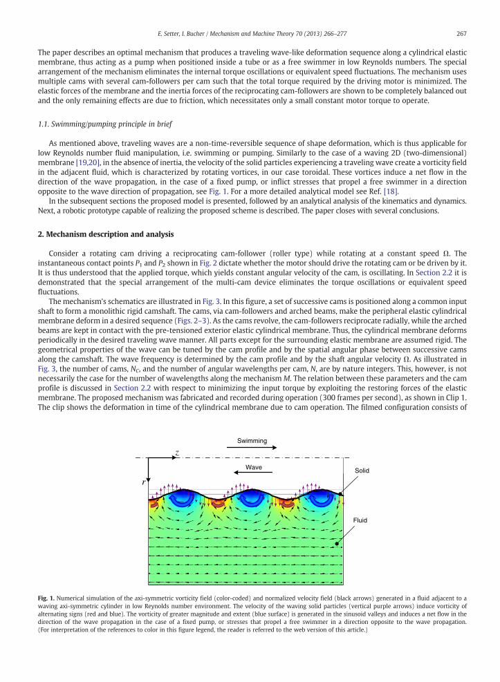
As mentioned above, traveling waves are a non-time-reversible sequence of shape deformation, which is thus applicable forlow Reynolds number fluid manipulation, i.e. swimming or pumping. Similarly to the case of a waving 2D (two-dimensional)membrane [19,20], in the absence of inertia, the velocity of the solid particles experiencing a traveling wave create a vorticity fieldin the adjacent fluid, which is characterized by rotating vortices, in our case toroidal. These vortices induce a net flow in thedirection of the wave propagation, in the case of a fixed pump, or inflict stresses that propel a free swimmer in a directionopposite to the wave direction of propagation, see Fig. 1. For a more detailed analytical model see Ref. [18].
In the subsequent sections the proposed model is presented, followed by an analytical analysis of the kinematics and dynamics.Next, a robotic prototype capable of realizing the proposed scheme is described. The paper closes with several conclusions.
2. Mechanism description and analysis
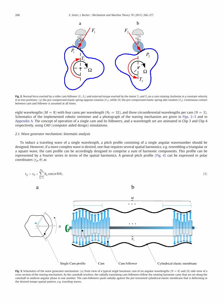
Consider a rotating cam driving a reciprocating cam-follower (roller type) while rotating at a constant speed Ω. Theinstantaneous contact points P1 and P2 shown in Fig. 2 dictate whether the motor should drive the rotating cam or be driven by it.It is thus understood that the applied torque, which yields constant angular velocity of the cam, is oscillating. In Section 2.2 it isdemonstrated that the special arrangement of the multi-cam device eliminates the torque oscillations or equivalent speedfluctuations.
The mechanism's schematics are illustrated in Fig. 3. In this figure, a set of successive cams is positioned along a common inputshaft to form a monolithic rigid camshaft. The cams, via cam-followers and arched beams, make the peripheral elastic cylindricalmembrane deform in a desired sequence (Figs. 2–3). As the cams revolve, the cam-followers reciprocate radially, while the archedbeams are kept in contact with the pre-tensioned exterior elastic cylindrical membrane. Thus, the cylindrical membrane deformsperiodically in the desired traveling wave manner. All parts except for the surrounding elastic membrane are assumed rigid. Thegeometrical properties of the wave can be tuned by the cam profile and by the spatial angular phase between successive camsalong the camshaft. The wave frequency is determined by the cam profile and by the shaft angular velocity Ω. As illustrated inFig. 3, the number of cams, NC, and the number of angular wavelengths per cam, N, are by nature integers. This, however, is notnecessarily the case for the number of wavelengths along the mechanism M. The relation between these parameters and the camprofile is discussed in Section 2.2 with respect to minimizing the input torque by exploiting the restoring forces of the elasticmembrane. The proposed mechanism was fabricated and recorded during operation (300 frames per second), as shown in Clip 1.The clip shows the deformation in time of the cylindrical membrane due to cam operation. The filmed configuration consists of
,
r
z
Wave
Swimming
Fluid
Solid
Fig. 1. Numerical simulation of the axi-symmetric vorticity field (color-coded) and normalized velocity field (black arrows) generated in a fluid adjacent to awaving axi-symmetric cylinder in low Reynolds number environment. The velocity of the waving solid particles (vertical purple arrows) induce vorticity ofalternating signs (red and blue). The vorticity of greater magnitude and extent (blue surface) is generated in the sinusoid valleys and induces a net flow in thedirection of the wave propagation in the case of a fixed pump, or stresses that propel a free swimmer in a direction opposite to the wave propagation.(For interpretation of the references to color in this figure legend, the reader is referred to the web version of this article.)
1F 2F
a b
1T
2T
1P2P
Ω Ω
Fig. 2. Normal force exerted by a roller cam follower (F1, F2) and external torque exerted by the motor T1 and T2 on a cam rotating clockwise in a constant velocityΩ in two positions: (a) the pre-compressed elastic spring opposes rotation (F1), while (b) the pre-compressed elastic spring aids rotation (F2). Continuous contactbetween cam and follower is assumed at all times.
268 E. Setter, I. Bucher / Mechanism and Machine Theory 70 (2013) 266–277
eight wavelengths (M = 8) with four cams per wavelength (NC = 32), and three circumferential wavelengths per cam (N = 3).Schematics of the implemented robotic swimmer and a photograph of the waving mechanism are given in Figs. 2–3 and inAppendix A. The concept of operation of a single cam and its followers, and a wavelength set are animated in Clip 3 and Clip 4respectively, using CAD (computer aided design) simulations.
2.1. Wave generator mechanism: kinematic analysis
To induce a traveling wave of a single wavelength, a pitch profile consisting of a single angular wavenumber should bedesigned. However, if a more complex wave is desired, one that requires several spatial harmonics, e.g. resembling a triangular ora square wave, the cam profile can be accordingly designed to comprise a sum of harmonic components. This profile can berepresented by a Fourier series in terms of the spatial harmonics. A general pitch profile (Fig. 4) can be expressed in polarcoordinates (rp, θ) as
Fig. 3. Scross-secamshathe des
rp ¼ r0 þXNH
n¼1
bn cos nN θð Þ; ð1Þ
N
a b
. . .
M
. . .
cN
Cam followerCamSingle Cam profile Cylindrical elastic membrane
chematics of the wave generator mechanism: (a) front view of a typical single harmonic cam of six angular wavelengths (N = 6) and (b) side view of action of the waving mechanism. As the camshaft revolves, the radially translating cam-followers follow the rotating harmonic cams that are set along theft in uniform angular phase to one another. The cam-followers push radially against the pre-tensioned cylindrical elastic membrane that is deforming inired tempo-spatial pattern, e.g. traveling waves.

where
whereand pgiven
N
T
2
N1
aa
fk
a bFig. 4. Computer-generated image of (a) a cross-section of a harmonic cam with three roller followers. The pitch profile is composed of a single harmonic withthree angular wavelengths (NH = 1, N = 3). The normal force exerted by the cam follower F and the external torque by motor T are shown in red. (b) Forcesacting on a cam follower (red): normal force due to cam contact F, normal forces due to linear bearing N1, N2, distributed elastic restoring forces due to cylindricalmembrane fk, and a general dissipative force f (roller follower rising).
269E. Setter, I. Bucher / Mechanism and Machine Theory 70 (2013) 266–277
r0 is the prime circle radius, NH is the number of harmonics comprising the pitch profile, N is the number of angular
wherewavelengths for the primary harmonic, θ = Ωt is the angle of rotation, and bn, n = 1,…,NH are the amplitudes of each of theharmonics. It is further assumed that the cam-followers are of the roller type and the cam profile is designed to yield the desiredpitch profile while compensating for the roller radius. Linear momentum balance on a cam follower (see for example Ref. [21,22])results in the force exerted by a single roller follower on a cam, assuming a thin follower (direction of dry friction force isembedded in the sign of the sine term):F ¼ f k þ crp þmf r€p
cos α−μ2Aþ B
B
� �sin α
; ð2Þ
c is the viscous damping coefficient, μ is Coulomb friction coefficient, fk is an elastic restoring force, α is the pressure angle,e length of the follower linear bearing, and A is the roller follower overhang (see Fig. 4).
B is thNeglecting shell flexural rigidity compared with membranic effects [23] and assuming axial symmetry and small deflections ofthe elastic cylindrical membrane, it can be shown that the radial restoring force is linear and the radial stiffness is given by
kS ¼ EwSd02
� �−2ð3Þ
E is the elasticity modulus, w is the membrane thickness, S is a surface fraction covered by an arched beam, and d0 is the
whereundeformed diameter of the elastic cylindrical membrane. The elastic radial restoring force exerted by the cylindrical membraneis now given byf k ¼ kS rp þ h−d02
� �ð4Þ
h is the follower length (Fig. 4). It is assumed at all times that the elastic cylindrical membrane maintains positive tensionrovides enough restoring force to prevent cam-follower disengagements. Moreover, the cam follower overhang (Fig. 4) isby
A ¼ A0− rP−r0ð Þ; ð5Þ

wherevector
270 E. Setter, I. Bucher / Mechanism and Machine Theory 70 (2013) 266–277
A0 is the mean overhang. The pressure angle, the angle between the normal to the pitch curve and the follower velocity(see Fig. 4) is given by [22] (with zero follower offset)
α ¼ tan−1 1rp
drpdθ
!; ð6Þ
ive pressure angle where the follower is ascending, i.e. drp/dθ N 0).
(positThe torque exerted by a single cam-follower on a single cam is given byT ¼ rp F sin α: ð7Þ
Substituting Eqs. (2)–(6) into Eq. (7) while exploiting cyclic symmetry of the design yields, after simplification, the torqueexerted by N circumferential cam-followers on a single cam
T ¼N ks rp þ h−d0
2
� �þ crp þmf rp
� �rpr
′pB
rpB−μ 2 A0−rp þ r0� �
þ Bh i
r′p; ð8Þ
r′p≜drp=dθ.
whereSince the torque load on each cam is periodic and since shaft torque oscillations should be eliminated, harmonic analysis of thetorque is proposed. To this end let us denote
T ¼ a0 þX∞k¼1
ak sin kNθþ φkð Þ; ð9Þ
a0 is the mean torque on a cam, ak and φk are the amplitude and phase of the kth harmonic respectively in the torque
wheresignal.It can be noticed from Eq. (8) that for the simple case where Coulomb friction is negligible (μ → 0), the torque on a cam is alinear combination of the terms r′p, rp r′p,rp r′p, and rp r′p. Assuming constant angular velocity (Ω) and relying on Eq. (1), the spatial(angular) frequencies of the torque contains energy at discrete, equally spaced spectral lines with respect to the rotation angle θand are given by {(n ± m)N}; n,m = 0,1,2,…NH. Moreover, the non-zero mean (DC) is contributed only by the term rpr′p, which ispreceded by the viscous damping coefficient. Furthermore, by averaging Eq. (8) over a period it can be shown that the meantorque on a single cam for negligible dry friction and non-negligible viscous damping, due to N circumferential cam-followers isgiven by
Th i����� μ ¼ 0c≠0
¼ 12cN3Ω
XNH
n¼1
n2a2n: ð10Þ
By assuming a pitch-profile of a single harmonic (NH = 1) with a small amplitude a1, expanding Eq. (8) in power series of thepitch radius amplitude a1, and averaging over a period, it can be shown that the mean torque on a single cam is given by a series ofeven powers of the amplitude a1. Even powers are expected since the mean non-zero torque due to friction cannot be affected bythe mathematical sign of the amplitude, which is equivalent to shaft rotation. The leading order term of the mean torque(assuming small amplitude) is then given by
Th i��� μ≠0c≠0a1≪1
≃ μa12 N
3kS2Br0
2A0 þ Bð Þ r0 þ h−d02
� �þ 12ca1
2N3Ω: ð11Þ
The expression given in Eq. (11) is a sum of positive components, where r0 + h − d0 / 2 N 0 as it represents the mean radialdisplacement of the elastic cylindrical membrane, which is assumed to maintain positive tension all times. The expressions inEqs. (10)–(11) are significant because, when multiplied by the number of cams NC, they represent the optimal (minimal)resultant shaft torque in the presence of viscous damping and dry friction, respectively, where torque oscillations have beeneliminated.
It follows that when both Coulomb friction and viscous damping are negligible, the torque on each cam oscillates with zeromean. However, when Coulomb friction is significant, its nonlinear contribution further increases the number of harmonicscomposing the periodic torque (Eq. (9)). In summary, the number of wavelengths in the desired wave NH as well as themagnitude of the dry friction μ determine the number of harmonics comprising the periodic torque on a single cam.

271E. Setter, I. Bucher / Mechanism and Machine Theory 70 (2013) 266–277
The resultant torque on the camshaft from summing up the torques on each cam can be put as
where
is theEq. (1
whereof par
if
where
Tt ¼XNcn¼1
T θð Þjθ¼θþ n−1ð ÞΔθ ð12Þ
Δθ ¼ 2πM
NNCð13Þ
uniform angular phase shift between successive cams along the camshaft to yield traveling waves. Substituting Eq. (9) into2) yields after some manipulations
Tt ¼ NCa0 þ IX∞k¼1
akei φkþkNθð ÞXNc
n¼1
rn−1
" #; r≜ei
2πkMNC ; ð14Þ
I[ ] extracts the imaginary part of a complex number. The last representation is convenient in determining the optimal setameters that minimizes the torque oscillations, as described below.
2.2. Eliminating torque oscillations
As stated above, assuming μ = c = 0 the mean torque is zero, i.e. a0 = 0 in Eqs. (9) and (14). It is demonstrated below thatthe residual oscillating terms in the complex series in Eq. (14) equal zero individually for every k, provided that k M is an integernumber and kM/Nc is a non-integer for k = 1, 2, 3,... K, where K is the highest harmonic of finite magnitude in Eq. (9).
Let us examine the complex geometric series
1þ r þ r2 þ r3 þ ⋯þ rNc−1 ¼XNc
n¼1
rn−1 ¼ 1−rNc
1−r; r≜ei
2πkMNC ; i≜
ffiffiffiffiffiffiffiffi−1
p: ð15Þ
From Eq. (15) it follows that
XNC
n¼1
ei n−1ð Þ2πkMNC ¼ 1−ei2πkM
1−ei2πkMNC
¼ 0 ð16Þ
kMNC
∉Z; kM∈Z; k ¼ 1;2; :::; ð17Þ
Z is the group of integer numbers. Substituting Eq. (16) into Eq. (14), while assuming Eq. (17) holds yields
Tt ¼ NC a0: ð18Þ
For μ ≠ 0 or c ≠ 0 it was shown that a0 ≠ 0, e.g. Eqs. (10)–(11). Hence, the mean total torque cannot be identically zero as itsmagnitude increases with the number of cams. However, its oscillation amplitude can be dramatically decreased by eliminatingthe harmonic sums in Eq. (14), provided that the assumptions made in Eq. (17) hold.
The last statement calls for optimization to find the optimal number of cams and wavelengths, given friction and dampingparameters. Within the scope of this paper, an optimal torque results in a minimum cost function J that represents input power(i.e. ohmic or thermal losses in a DC motor) or minimal root mean square (RMS) over one shaft revolution (minimum signalenergy):
minM;NC
J ¼ 12π
ffiffiffiffiffiffiffiffiffiffiffiffiffiffiffiffiffiffiffiffiffiffiffiffiZ2π0
Tt2 θð Þdθ
vuuut : ð19Þ
This definition accounts for both mean magnitude and oscillation amplitude. Other optimization definitions may assigndifferent weights to the mean torque or oscillation amplitude.
0 2 4 6
−0.1
−0.05
0
0.05
0.1
0.15a
Shaft angle θ [rad]
Tor
que
[Nm
]
0 2 4 6
−0.1
−0.05
0
0.05
0.1
0.15b
Shaft angle θ [rad]
Tor
que
[Nm
]
T1
T2
T3
T4
Tt
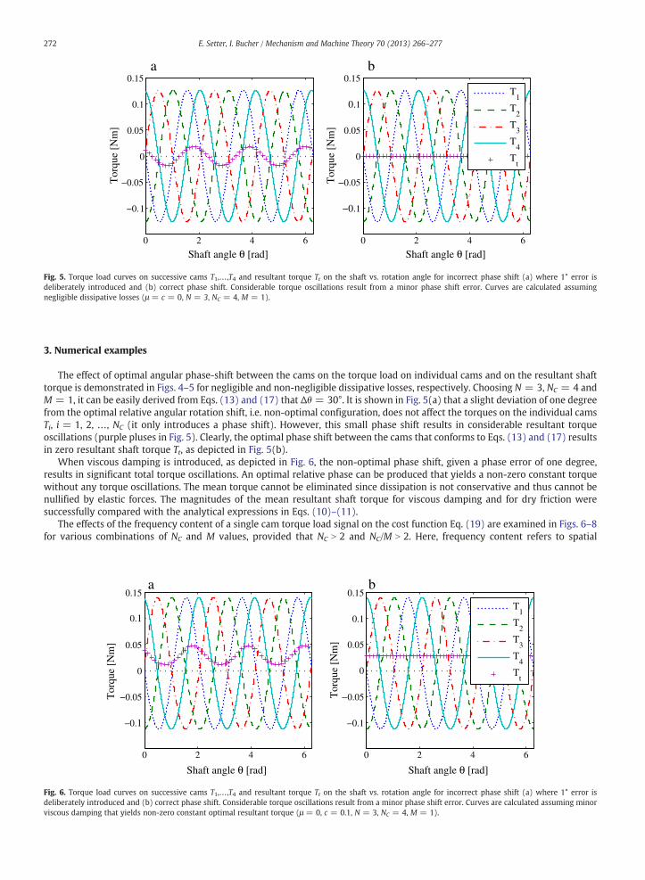
Fig. 5. Torque load curves on successive cams T1,…,T4 and resultant torque Tt on the shaft vs. rotation angle for incorrect phase shift (a) where 1° error isdeliberately introduced and (b) correct phase shift. Considerable torque oscillations result from a minor phase shift error. Curves are calculated assumingnegligible dissipative losses (μ = c = 0, N = 3, NC = 4, M = 1).
272 E. Setter, I. Bucher / Mechanism and Machine Theory 70 (2013) 266–277
3. Numerical examples
The effect of optimal angular phase-shift between the cams on the torque load on individual cams and on the resultant shafttorque is demonstrated in Figs. 4–5 for negligible and non-negligible dissipative losses, respectively. Choosing N = 3, NC = 4 andM = 1, it can be easily derived from Eqs. (13) and (17) that Δθ = 30°. It is shown in Fig. 5(a) that a slight deviation of one degreefrom the optimal relative angular rotation shift, i.e. non-optimal configuration, does not affect the torques on the individual camsTi, i = 1, 2, …, NC (it only introduces a phase shift). However, this small phase shift results in considerable resultant torqueoscillations (purple pluses in Fig. 5). Clearly, the optimal phase shift between the cams that conforms to Eqs. (13) and (17) resultsin zero resultant shaft torque Tt, as depicted in Fig. 5(b).
When viscous damping is introduced, as depicted in Fig. 6, the non-optimal phase shift, given a phase error of one degree,results in significant total torque oscillations. An optimal relative phase can be produced that yields a non-zero constant torquewithout any torque oscillations. The mean torque cannot be eliminated since dissipation is not conservative and thus cannot benullified by elastic forces. The magnitudes of the mean resultant shaft torque for viscous damping and for dry friction weresuccessfully compared with the analytical expressions in Eqs. (10)–(11).
The effects of the frequency content of a single cam torque load signal on the cost function Eq. (19) are examined in Figs. 6–8for various combinations of NC and M values, provided that NC N 2 and NC/M N 2. Here, frequency content refers to spatial
0 2 4 6
−0.1
−0.05
0
0.05
0.1
0.15
Shaft angle θ [rad]
Tor
que
[Nm
]
0 2 4 6
−0.1
−0.05
0
0.05
0.1
0.15
Shaft angle θ [rad]
Tor
que
[Nm
]
T1
T2
T3
T4
Tt
a b
Fig. 6. Torque load curves on successive cams T1,…,T4 and resultant torque Tt on the shaft vs. rotation angle for incorrect phase shift (a) where 1° error isdeliberately introduced and (b) correct phase shift. Considerable torque oscillations result from a minor phase shift error. Curves are calculated assuming minorviscous damping that yields non-zero constant optimal resultant torque (μ = 0, c = 0.1, N = 3, NC = 4, M = 1).

0 10 20 300
0.05
0.1
0.15
0.2
Spatial (angular) frequency
Cam
−to
rque
har
mon
ic a
mp.
[N
m]
0 1 2 3 4 5 6 7 8 9 10
0
10
200
0.5
1
1.5
M (# wavelengths)Nc (# cams)
Shaf
t tor
que
RM
S [N
m]
7 810
0.2
0.4
0.6
0.8 k=1
k=2
a b
Fig. 7. (a) RMS of the shaft torque (Eq. (19)) plotted vs. number of cams and number of wavelengths in the mechanism, plotted for μ = c = 0, N = 3, NH = 1NC N 2, and Nc/M N 2. (b) Harmonic decomposition of the spatial (angular) frequencies of the torque on a single cam for μ = c = 0, N = 3, NH = 1. Where nodissipation is present the optimal shaft torque RMS can be set to zero, as appears here in the single harmonic cam (NH = 1) along the lines of an integer numberof wavelengths (M∈Z).
273E. Setter, I. Bucher / Mechanism and Machine Theory 70 (2013) 266–277
(angular) frequencies that compose the torque on a single cam, i.e. the amplitudes ak for each harmonic index k = 0, 1, 2,... inEq. (9).
As stated above, for a cam with a single harmonic profile (NH = 1) and no dissipative losses, the torque signal is composed ofonly two harmonics with zero mean. Indeed Fig. 6(a) shows that the resultant shaft torque RMS is zero along the lines of M∈Zwhere the conditions in Eq. (17) are met, since k = 1 or 2 and NC N 2. It can also be noted that the cam torque contains twoharmonics and zero mean from the harmonic decomposition Fig. 6(b).
In the presence of dissipative losses, e.g. dry friction or viscous damping, the mean resultant shaft torque is always non-zero,since the dissipative forces are non-conservative and cannot be eliminated by any phase setting of the elastic restoring forcesacting on the cams. Indeed it can be noted from Fig. 8(a), where viscous damping is introduced into the model (c = 0.5 N s/mm),that the optimal shaft torque RMS (minima area) is non-zero and increases with the number of cams, as predicted by Eq. (14).Moreover in Fig. 8(b) a non-zero component is present in the spatial frequency content.
As can be noted from Eq. (8), dry friction or a multi-harmonic cam-profile give rise to higher harmonics in the cam torquesignal, which must be considered if the conditions in Eq. (17) are to be satisfied. In Fig. 9(a)–(b) the shaft torque RMS and theharmonic decomposition of the torque on a single cam are presented respectively for non-negligible friction and multi-harmonicscam profile (μ = 0.8, NH = 7). It is evident that higher harmonics are indeed present, which leads to non-trivial combinations forwhichkM=NC∈Z, thus violating the conditions in Eq. (17) that are required to guarantee no shaft torque oscillations. Indeed, it can
0 10 20 300
0.05
0.1
0.15
0.2
Spatial (angular) frequency
Cam
−to
rque
har
mon
ic a
mp.
[N
m]
0 1 2 3 4 5 6 7 8 9 10
0
10
200
0.5
1
1.5
M (# wavelengths)Nc (# cams)
Shaf
t tor
que
RM
S [N
m]
810
0.2
0.4
0.6
0.8
1
k=1
k=0 k=2
a b
Fig. 8. (a) RMS of shaft torque (Eq. (19)) plotted vs. number of cams and number of wavelengths in the mechanism, plotted for μ = 0, c = 0.5Ns/mm, N = 3,NH = 1, NC N 2, and Nc/M N 2. (b) Harmonic decomposition of the spatial (angular) frequencies of the torque load on a single cam for μ = 0, c = 0.5Ns/mm, N = 3,NH = 1. Dissipation results in non-zero mean cam torque and shaft torque. The shaft torque RMS increases with the number of cams.

0 1 2 3 4 5 6 7 8 9 10
0
10
200
2
4
6
8
M (# wavelengths)Nc (# cams)
Shaf
t tor
que
RM
S [N
m]
101
2
3
4
5
6
7
0 10 20 300
0.05
0.1
0.15
0.2
Spatial (angular) frequency
Cam
−to
rque
har
mon
ic a
mp.
[N
m]
k=0
k=1
k=2
k=3
k=4
k=5
. . .
kM/Nc∈Za b
k=6
Fig. 9. (a) RMS of shaft torque (Eq. (19)) plotted vs. number of cams and number of wavelengths in the mechanism for μ = 0.8,N = 3,NH = 7,NC N 2, and Nc/M N 2.(b) Harmonic decomposition of the spatial (angular) frequencies of the torque on a single cam for N = 3, μ = 0.8, NH = 7. Dry friction and cam profile ofmulti-harmonics (NH N 1) give rise to higher harmonics in the cam torque, which results in torque oscillations as indicated by high RMS values, along the lines wherekM=MC∈Z; k ¼ 1;2;3; :::.
274 E. Setter, I. Bucher / Mechanism and Machine Theory 70 (2013) 266–277
be noted that considerable RMS magnitudes are found along the lines where kM=NC∈Z in Fig. 9(a). In this more realistic case, aninteger number of wavelengths (M∈Z) is definitely not sufficient to obtain no torque oscillations, and more careful attention isrequired in the design.
4. Proposed applications
As discussed above, the proposedmechanism can be utilized to drive traveling surface waves for means of fluid manipulations,i.e. perform as a pump or a free swimmer in low Reynolds environments that are common in extremely viscous fluids or in microscales.
A pump can be realized in a manner similar to that depicted in Fig. 10. In this configuration, the waving mechanism is placedinside a pipe filled with fluid. As the waves propagate along the mechanism, the fluid that is trapped between the waving surfaceand the pipe wall is pushed forward in the direction of the wave propagation. Since this type of pump does not involve anyrotating or mating parts that are in contact with the fluid, it allows a low shearing rate, which makes it favorable in conveyingshear sensitive particles or molecules as in biological applications.
If the pump was released from its fixations, it would perform as a swimmer. Indeed, a robotic swimmer was designed,fabricated and tested in highly viscous silicone fluid (60,000 cSt). The robotic swimmer (50 cm long 60 mm wide) is depicted inFig. 11. The swimmer is wireless and is propelled by the proposed waving mechanism. The swimmer includes on-board powersource (batteries) and microprocessor that generates controlled PWM (pulse width modulation) signals to drive a DC motor thatrotates the camshaft (Appendix A). The desired speed and direction commands are transmitted from a remote computer usingBluetooth™ communication. The swimmer transmits back the motor speed (magnetic encoder) and swimmer orientation (staticaccelerometers). The position of the swimmer is traced by a video camera. Experimental investigation of the effects of wavelengthand wave velocity on the swimming speed and comparison with an analytical model is given in Ref. [18]. The waving surface ofthe experimental robotic swimmer is shown in Clip 1 and a zoomed out view of free swimming is given in Clip 2.
Pipe Wavingmechanism
Fluidinlet
Fluidoutlet
Fixing strutsFixing struts
wave
a b
Fig. 10. Front view (a) and side view (b) of a schematic illustration of a proposed realization of an inline pump for viscous fluids using the described wavingmechanism. The pump is installed in the center of a pipe by fixing struts. The fluid trapped in the circumferential gap between the waving mechanism and thepipe wall is forced to move in the direction of the wave propagation.

Fig. 11. An image of the experimental robotic swimmer employing the proposed mechanism. The swimmer is placed in a tank of silicone fluid (kinematic viscosityof 60.000 cSt) tracked by a video camera. The swimmer in the image is held fix to capture better the waving surface. In the swimming experiment, the fixtures areremoved and the swimmer is free to propagate (in the direction opposite to the direction of wave propagation).
275E. Setter, I. Bucher / Mechanism and Machine Theory 70 (2013) 266–277
5. Conclusions
A multi-cam mechanism that generates traveling waves along a cylindrical elastic membrane as a means for propulsion/pumping was analyzed, designed and fabricated. Analytical and numerical demonstrations showed that an optimized angularshift between successive cams can be found in order to ensure minimal internal input torque. A constant non-oscillating resultantshaft torque is obtained if the number of wavelengths times spatial frequency index is an integer kM∈Z; k ¼ 1;2;3; :::ð Þ and thelast multiplication over the number of cams is a non-integer kM=NC∉Z. The second condition is important when the torque on asingle cam is composed of several spatial (angular) frequencies, as in the case of multi-harmonic cam profile or when dry frictioncannot be ignored. It was demonstrated that for a cam of single harmonic profile, assuming no dissipation, the torque signal iscomposed of only two harmonics with zero mean. Thus the resultant shaft torque can be set to zero. In this configuration thecircumferential elastic cylindrical membrane deforms as a traveling wave, thus remaining in a state of equi-elastic-potentialsurface. The optimal resultant shaft torque in the case where dissipative losses, e.g. dry friction or viscous damping, are present isa non-zero constant. Where dissipation cannot be ignored, it was found that the optimal residual mean torque is proportional tothe damping or friction magnitude, proportional to the pitch profile amplitude squared, and proportional to the number ofcircumferential wavelengths cubed. In the case of viscous damping the residual torque is also proportional to the angular velocityof rotation, and in the case of dry friction the residual torque is proportional to the mean restoring elastic force.
Numerical examples demonstrated the validity of the required conditions for eliminating shaft torque oscillations with respectto spatial frequency content of torque signals. Moreover, the numerically calculated magnitudes of the mean shaft torque wheredissipation losses are present were compared successfully to the analytical model and approximation.
A prototype robot applying the proposed wavingmechanismwas designed, fabricated and tested successfully as a swimmer inviscous fluid.
Supplementary data to this article can be found online at http://dx.doi.org/10.1016/j.mechmachtheory.2013.07.017.
Acknowledgments
The authors wish to acknowledge Mr. Amir Setter, Dr. Harel Plat, and Mr. Nadav Cohen, for fruitful discussions.
276 E. Setter, I. Bucher / Mechanism and Machine Theory 70 (2013) 266–277
Appendix A. Implementation of the proposed mechanism: A robotic swimmer
Microprocessor,
accelerometers,
tele-communication
circuit Oldham couplingArched beam
Rechargeable
batteries
GearedDC motor
Magneticencoder
Virtualcut
Camshaft
Roller type
cam-follower Charging port
Program downloading
port
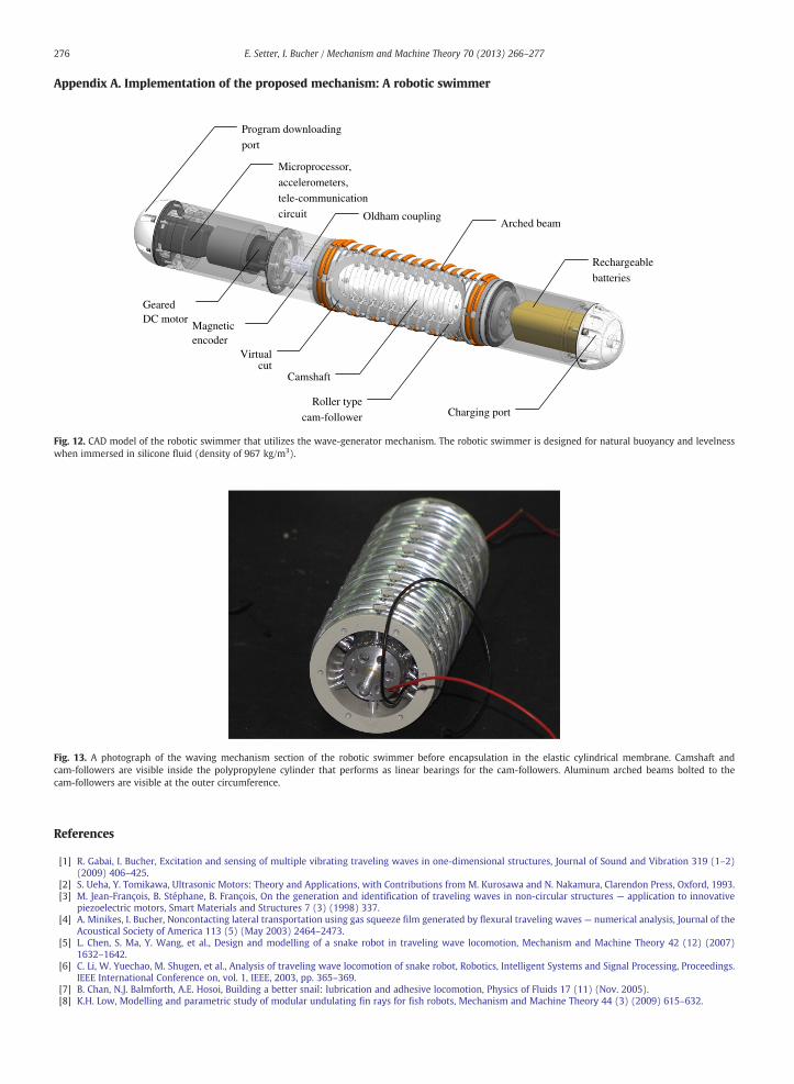
Fig. 12. CAD model of the robotic swimmer that utilizes the wave-generator mechanism. The robotic swimmer is designed for natural buoyancy and levelnesswhen immersed in silicone fluid (density of 967 kg/m3).
Fig. 13. A photograph of the waving mechanism section of the robotic swimmer before encapsulation in the elastic cylindrical membrane. Camshaft andcam-followers are visible inside the polypropylene cylinder that performs as linear bearings for the cam-followers. Aluminum arched beams bolted to the
cam-followers are visible at the outer circumference.References
[1] R. Gabai, I. Bucher, Excitation and sensing of multiple vibrating traveling waves in one-dimensional structures, Journal of Sound and Vibration 319 (1–2)(2009) 406–425.
[2] S. Ueha, Y. Tomikawa, Ultrasonic Motors: Theory and Applications, with Contributions from M. Kurosawa and N. Nakamura, Clarendon Press, Oxford, 1993.[3] M. Jean-François, B. Stéphane, B. François, On the generation and identification of traveling waves in non-circular structures — application to innovative
piezoelectric motors, Smart Materials and Structures 7 (3) (1998) 337.[4] A. Minikes, I. Bucher, Noncontacting lateral transportation using gas squeeze film generated by flexural traveling waves — numerical analysis, Journal of the
Acoustical Society of America 113 (5) (May 2003) 2464–2473.[5] L. Chen, S. Ma, Y. Wang, et al., Design and modelling of a snake robot in traveling wave locomotion, Mechanism and Machine Theory 42 (12) (2007)
1632–1642.[6] C. Li, W. Yuechao, M. Shugen, et al., Analysis of traveling wave locomotion of snake robot, Robotics, Intelligent Systems and Signal Processing, Proceedings.
IEEE International Conference on, vol. 1, IEEE, 2003, pp. 365–369.[7] B. Chan, N.J. Balmforth, A.E. Hosoi, Building a better snail: lubrication and adhesive locomotion, Physics of Fluids 17 (11) (Nov. 2005).[8] K.H. Low, Modelling and parametric study of modular undulating fin rays for fish robots, Mechanism and Machine Theory 44 (3) (2009) 615–632.

277E. Setter, I. Bucher / Mechanism and Machine Theory 70 (2013) 266–277
[9] S. Childress, Mechanics of Swimming and Flying, 1981.[10] N. Cohen, J.H. Boyle, Swimming at low Reynolds number: a beginners guide to undulatory locomotion, Contemporary Physics 51 (2) (2010) 103–123,
(2010/03/01).[11] C. Brennen, H. Winet, Fluid mechanics of propulsion by cilia and flagella, Annual Review of Fluid Mechanics 9 (1) (1977) 339–398.[12] J.J. Abbott, K.E. Peyer, M.C. Lagomarsino, et al., How should microrobots swim? International Journal of Robotics Research 28 (11-12) (2009) 1434–1447,
(November/December 2009).[13] A.H. Meng, N.-T. Nguyen, R.M. White, Focused flow micropump using ultrasonic flexural plate waves, Biomedical Microdevices 2 (3) (2000) 169–174.[14] K. Nakahara, K. Yoshimura, Y. Okayama, et al., A peristaltic micropump using traveling waves of polymer membranes driven by a single actuator, Micro
Electro Mechanical Systems (MEMS), IEEE 24th International Conference on, 2011, pp. 1083–1086.[15] B.J. Nelson, I.K. Kaliakatsos, J.J. Abbott, Microrobots for minimally invasive medicine, Annual Review of Biomedical Engineering 12 (1) (2010) 55–85,
(2010/07/01).[16] E. Setter, I. Bucher, Flexural vibration patterning using an array of actuators, Journal of Sound and Vibration 330 (6) (2011) 1121–1140.[17] M.P. Norton, Fundamentals of Noise and Vibration Analysis for Engineers, Cambridge University Press, 1989.[18] E. Setter, I. Bucher, S. Haber, Low-Reynolds-number swimmer utilizing surface traveling waves: analytical and experimental study, Physical Review E 85 (6)
(2012) 066304.[19] E. Lauga, T.R. Powers, The hydrodynamics of swimming microorganisms, Reports on Progress in Physics 72 (9) (Sep. 2009) 36.[20] G. Taylor, Analysis of the swimming of microscopic organisms, Proceedings of the Royal Society of London. Series A: Mathematical and Physical Sciences 209
(1099) (Nov. 22, 1951) 447–461.[21] H.A. Rothbart, Cam Design Handbook, McGraw-Hill, 2004.[22] J.K. Mills, L. Notash, R.G. Fenton, Optimal design and sensitivity analysis of flexible cam mechanisms, Mechanism and Machine Theory 28 (4) (1993)
563–581.[23] S. Timoshenko, S. Woinowsky-Krieger, Theory of Plates and Shells (Engineering Societies Monographs), 2nd ed. McGraw-Hill, 1959.