The Use of Chlorine Gas for Disinfecting Well Water ...pdf.usaid.gov/pdf_docs/PNABR405.pdf · The...
41
LOCAL FDEVEL. O M E T I - PROVI r\ C I A L F.,jANCEF) BY IS AGENCY l-O- IN1 RNATIONAL DEVELOrMEN r The Use of Chlorine Gas for Disinfecting Well Water Supplies Serving Villages in Giza Governorate Funded Unaer: USAID Contract Mo.: 263-0182-C-00-8041-00 Project No.: 263-0182 February 1992 PWS4-03 (E) TI,^V .fb - Fax: 3608472 Chemonica / 6 El F~wakeh 3tre / et Mohandiftarn, , iro / Tel.: 3602545, 348k247 / .-- ,89 6 / Telex: 93037 I.rv ,, / v a ,,,.. / r.roo r arriv cq.... / i /i .-,I.,Jdl A 2000 M Bt.. N.W./ W,.hlngton, o.c.20036/ Tl.: (2021 466-5340/ Fx [202 331-E202/ T1h.' 440361CHNC UI
Transcript of The Use of Chlorine Gas for Disinfecting Well Water ...pdf.usaid.gov/pdf_docs/PNABR405.pdf · The...

LOCAL FDEVEL O M E T I - PROVI r C I A L
FjANCEF) BY IS AGENCY l-O- IN1 RNATIONAL DEVELOrMEN r
The Use of Chlorine Gas for Disinfecting Well Water Supplies
Serving Villages in Giza Governorate
Funded Unaer USAID Contract Mo 263-0182-C-00-8041-00
Project No 263-0182
February 1992 PWS4-03 (E)
TI^V fb -
Fax 3608472 Chemonica 6 El F~wakeh 3tre etMohandiftarn iro Tel 3602545 348k247 -- 89 6 Telex 93037
Irv v a rroo r arriv cq i i -IJdl A 2000 M Bt NW Whlngton oc20036 Tl (2021 466-5340 Fx [202 331-E202 T1h 440361CHNC UI
The Use of Chlorine Gas for Disinfecting Well Water Supplies
Serving Villages in Giza Governorate
Chemonics LD II-P
February 1992 PWS4-03 (E)
TABLE OF CONTENTS
Introduction 1 Background of this Report 1 Purpose of this Report 1
Methods and Findings of Evaluation 2
Layout of Existing Chlorine Injection System 2 Operating Safety Precautions 2 Water Quality 2 Operating Procedures and Running Costs 5
Conclusions 8
Recommendations 9
Appendices
A - Field Trip Reports 12 B - Chemistry of Modern Chlorination 15 C - Powdered Chlorine Dosing Equipment 25 D - Specifications For Installing Gas Chlorine Dosing Equipment 30
Figures
Figure 1 - Chlorine Dosing Giza Water Pump Station 3 System Layout Giza Governorate
Figure 2 - Chlorine Dosing Giza Water Pump Station 10 Proposed Layout Giza Governorate
Tables
Table 1 - Results of Water Quality Analysis 6 Giza Governorate
INTRODUCTION
Many rural communities in Egypt depend on piped potable water drawn from deep wells This water is usually free from bacterial pollution as the living organisms die within about 30 m of the pollution source Sometimes however well water becomes contaminated by polluted surface water that short circuits the percolation path by running down the outside of the well casing
The most common problem in rural communities is polluted subsoil water that enters pipelines and contaminates the water used by consumers This occurs when networks are not continuously full of water The action of water draining fromn a pipeline when the supply is shut off creates a vacuum in the pipes causing subsoil water o be drawn in through defective joints
Background for this Report
Two events crystalized the need for this report First consulting engineers found bacterial contamination in the four village networks tested during the preparation of the report Evaluating the Loss Reduction Program in Four Villages (August 1991) The four villages are in the governorates of Gharbiya Menufiya Qalubiya and Sharqiya
Second Giza Governorate spent third-year LD I-P funds to install six gas chlorinators These disinfect local well water supplied to Awsim City and the villages of Abu GhalebBirqash Bertes El Barageil Kom El Ahmer and Monshat El Qanater
The governorate has allocated fourth-cycle funds to install 10 more chlorinators at El Aiat City and El Qatoury in Markaz El Aiat Abu Nomros City and Manyel Sheiha in Markaz Abu Nomros E1 Mansoriya Kafr Hegazy Werdan Nakla and Gezert Mohamed in Markaz Awsim and El Hawamdiya City
Purpose of this Report
The purpose of this report is to evaluate the existing chlorine injection installations The data collected can then be used to recommend
How best to implement the twelve new units in Giza o How other governorates might replicate the practice of
disinfecting local water supplies
1
METHODS AND FINDINGS OF EVALUATION
Field visits were made on 29 September and 10 October 1991 to inspect the chlorine injection installations and examine the quality of water at Awsim City and the villages of Bertes and Monshat El Qanater in Awsim Markaz
Four items were e~aluated
Layout of existing chlorine injection system
Operating safety precautions
Water quality Operating procedures and running costs
Layout of Existing Chlorine injection System
At the six pump stations with chlorine systems the chemical is injected downstream of the last well branch pipe A schematic of the ge2neral layout of the existing chlo-ine injection system iLshown in Figure 1
Disadvantages of this arrangement are
Insufficient chlorine contact time before the first consumer connection
Consumer demands cause variations in flow rates but the chlorine dose rate is constant Hence there are variations in the concentration of chlorine
Chlorine gas is supplied from 70 kg cylinders Two cylinders are connected to the system one on-line and the other on standby A vacuum dispensing system controls the flow of chlorine gas to the solution feed which injects into the pumpstation outlet pipe downstream of the well branch pipes as shown in Figure 1
Giza Gevernorate uses Spanish-made Fischer amp Porter cylinder-mounted chlorine gas dispensing units with a maximum gas dose rate of two kghour The units were supplied by a local import agent who stocks spare parts
Two three hp pumps (one on-line the other on standby) feed an ejector in the solution feed pipe that creates the vacuum necessary to operate the gas dispenser Gas flow rates are set on a wall-mounted rotameter calibrated from 01 to 20 kghourNon-corrodible tubing conveys the gas and chlorine solution around the system
2
CHLORINE DOSING - GIZA WATER PSEXISTING LAYOUT
t WATER TOWER
WELLS
- WELLS
(S S CHLORINE STORE amp
CCJNTROL ROOM
SOLUTION LINE
CHLORINE SOLUTlON
Um T rNETWORK
Figure 1
3
At the three stations visited the gas and solution pumpcontrols are housed in the same room used to store chlorine gas cylinders This is an unsafe practice
Safety Precautions
Some commendable safety precautions practiced at the stations visited included
Storing chlorine gas cylinders in the shade and out of direct sunlight
Securing gas cylinders connected to vacuum regulatorsin an upright position This guards against accidental fracture of gas pipes caused by cylinders falling over
Providing filter type gas masks for use in the event of a minor gas escape
Using non-corrodible tubing for all chemical lines Housing gas cylinders and chlorine flow controls in a
building not normally occupied by operators (Thisapplies to Awsim Pump Station only At Bertes PumpStation the chlorine gas cylinders and gas controls are all housed in the building occupied by the pump operators Furthermore the gas masks were kept in the same room as the chlorine cylinders)
Additional precautions that should be introduced include
Storing the chlorine cylinders in a well-ventilated shaded and secure room that is separate from the room housing the chlorine controls and solution punips
Providing ammonia soiution for regularly checking gas joints for chlorine leaks
Leaving valve operating keys in position on in-use gas cylinders
Installing a water point and hose for spraying the gascylinders in the event of an emergency accidental gas leak
Water Quality
Water samples were collected fiom various points on the water systems serving Awsim City and the villages of Bertes and Monshat El Qanater which are both in Awsim Markaz The samples were tested to determine the quality of water in the wells and networks by analyzing bacterial pnllution free available chlorine p1 electrical conductivity and clarity The
4
clarity test shows any adverse reaction caused by chlorine oxidizing dissolved iron or manganese in the water
Fecal coliform counts were analyzed using the Milliporemembrane filter method and field equipment Cultures were prepared on-site immediately after collecting samples thus avoiding the need to de-chlorinate the water samples All samples for bacterial examination were collected from faucets that were first flamed and then flushed for several minutes to ensure the sample represented water from the distribution main rather than the service pipe
Free available residual chlorine was determined using N-diethyl-p-phenylene-diamine (DPD) powder and a color comparator The pH a measure of the alkalinityacidity of the water and electrical conductivity were measured on-site using a portable instrument Electrical conductivity (FC) is proportional to the concentration of total dissolved solids (TDS) in the water usually TDS is EC x 08 Water clarity was judged by observing a water sample in a clear glass container
Table 1 shows the results of water quality tests on samplesfrom Awsim Bertes and Monshat El Qanater Two sets of samples were taken on different days from the Bertes water system On the first occasion the chlorinator had not operatedlong enough for a chlorine residual to reach the end of the network
During the first visit to Bertes village the operating well had slight fecal pollution Significant to serious fecal pollution was also found in samples taken about 200 m from the pump station and at the end of the network No fecal pollution was found at points where free residual chlorine was evident
The water quality results show dosing of chlurine is effective at Awsim City and Monshat El Qanater village when free available chlorine is detected at the extremities of the distribution system The zero bacteria count on samplesanalyzed at Monshat El Qanater and Bertes (second visit) confirm that a residual chlorine concentration of 05 mgL at the end of the network is sufficient to eliminate bacterial pollution
The water was bright and clear at all the sample pointssignifying the absence of iron or manganese precipitant
Operating Procedures and Running Costs
There are no total flow meters to measure the quantity of water supplied ta distribution Hence chlorine dose rates cannot be based on water demands which fluctuate during the
5
TABLE 1
RESULTS OF WATER QUALITY ANALYSIS GIZA GOVERNORATE AWSM CITY BERTES AND MONSHAT EL QATARA WATER SYSTEMS
Sample Location
BereSystem- 29th September 1991 1 Untreated well water 2 15 m downstream of solution point 3 End of network 4 Mid-point of network 5 Network 30 m downstream of PS 8 As soriple 3 3 hrs later 9 As sampe 4 3 hrs later
Awslm_Ctty - 29thSeptember 1991 6 Mid-point of network 7 End of network
Berates System - 10th October 1991 A As 1 untreated well water B As 2 15 m from solution poirt C As 3 end of network
Monshat El Qatara System -10 October 19 D Untreated well water E 15 m downstream of solution point F End of network G Health clinic mid-network
BrightClear BrightClear BrightClear BrightClear BrightClear BrightClear BrightClear
BrightClear BriqhtClear
BrightClear BrightClear BrightClear
BrightClear BrightClear BrightClear BrightClear i
Analysls Results pH Residual Fecal
Chlorine Collforms Remarks mmL 100 mL
3 Chlorine dose rate 1 kghr ie 69 mgI for pump flow + 25 0 rate of 40 Vs Pump outlet is unmetered
Vamp innumerabliE_ 0 155
1 8 0 Not tested 0 Not tested
05 Not tested Chlorine dose rate 1 kghr ie345 mgI for pump flow 0 5 Not tested rate of 80 Is Pump outlet is unmetered
603 0 Chlorine dose rate 1 kghr ie 6 9 mgl for pump flow 620 + 25 0 rate of 40 Us Pump outlet is unmetered 607 06 0
6 04 __9 -Chlorine dose rate 06 kghr ie 42 mgI for pump flow 645 + 25 0 rate of 40 Vs Pump outlet is unmetered 6 80 05 6981 25 01
day Instead chlorine doses are set so there is a minimum chlorine residual of 05 mgL at the end of networks Normally this residual is achieved by injecting chlorine at the rate of 10 kghour for an hour when the pumps are started each morning and reducing the dose for the remainder of the operating day to 06 kghour
Each day the pump stations are operated for an average of 15 hours For maximum protection and benefit the chlorinators must operate all the time water is delivered to the distribution network From discussions with operators it seems chlorine is not injected continuously which could account for zero residuals during the first visit to Bertes
If chlorine is injected for 15 hours a day at a rate of 06 to 10 kgh the estimated chlorine consumption is 8 kgday This concurs with the operating staff report that a 70 kg chlorine cylinder lasts about 10 days
The additional recurrent operating cost of dosing water supplies with chlorine includes the cost of power chlorine test chemicals and maintenance of chemical solution pumpsand gas dispensing equipment In Giza these additional costs are estimated as follows
CAPITAL COSTS LE
Purchase price of chlorine equipment and dosing pumps 37000
ADDITIONAL OPERATING COSTS
10-year write-off of equipment 3700
Electricity cost for 3 hp solution pump at LE 010kwh 1200
Chlorine Sas at LE 040kg 1200
Water quality and gas detection chemicals 200
Estimated pump gas dosing equipment and gas mask maintenance costs 500
TOTAL ANNUAL ADDITIONAL OPERATING COST LE 6800
None of the well pump stations have water meters on the outlet pipes to measure water production Consequently it is possible only to estimate the unit cost of treating water with chlorine based on the rated output of the pumps
7
At Bertes and Monshat El Qanater the pump rates are 40 Ls
yielding the following unit costs
LE 1863day
LE 086100 m3 of water produced
LE 172100 m3 water consumed (50 losses)
There are no readily available figures on the normal operating costs of pump stations but it is estimated that the electricity
3costs for pumping water from wells is LE 600 per 100 m hence there is a 14 percent additional cost for injecting chlorine
LE 1863 a day is a small price to pay for disinfecting the public water supply
CONCLUSIONS
1 The prevalence of intermittent supplies from leakingpipe networks often causes consumers receive water that is polluted Thus there is an urgent and widespread need for disinfection of water by local communities
lIt 2 The use of chlorine for disinfecting small local water
supply systems the following distinct advantages over other disinfection methods
Chlorine injected in sufficient quantities will leave a chlorine residual in solution that protects the water from minor re-contamination from leaking networks
Traces of free chlorine residual can be detected usingsimple and cheap test kits This is a good indication that water is safe to drink without using complex procedures to identify bacteria counts
Appendix B provides additional information about the chlorination of water supply systems
3 The evaluation of the chlorine dosing systems in Giza Governorate show that the chlorine gas injection facilities at Awsim City and the village of Bertes and are effective at providing water safe for human consumption if the equipment is used correctly
4 Some safety precautions are lacking
8
5 Rearrangement of future chlorine dosing layouts as shown in Figure 2 would provide additional benefits at no greater expense than the current chlorine dosinglayout shown in Figure 1
6 When pipelines that leak are under pressure water containing hlorine eszapes and polluted water entering empty pipes increases the chlorine demand Significant cost savings will result by reducing pipe leakage
AR 1 7 Although the f-imilALgas poundhlorine devices could be replicated by other governorates chlorine gas -s highly dangerous if mishandled by untrained operatorsPowdered chlorine offers a preferred alternative for rural water systems Appendix C illustrates two possible layouts for dispensing powdered chlorine
RECOMMENDATIONS
Recommendations stemming from this study are grouped into essential and desiable recommendations The essential recommendations cover the safety aspects of using gas
chlorine systems whereas the desirable recommendations are meant to improve efficiency and reduce running costs
Giza Governorate can install the 10 additionalchlorine dosing systems at El Aiat City and El Qatoury in Afarkaz El Aiat Abu Nomros City and Manyel Sheiha in Markaz Abu Nomros El Manso-iya Kafr Hegazy Werdan Nakla and
Gezert Mohamed in Markaz Awsim and El Hawamdiya Cityusing LD H-P fourth-cycle funds provided the following essential recommendations are followed
Essential Recommendations
1 Store all chlorine gas cylinders in a secure room withground level ventilation Access to the chlorine store room should be restricted to authorized personnel trained in handling chlorine cylinders
2 Restrain chlorine cylinders that are in use to preventaccidental overturning and have valve keys left on the cylinder outlet valves These keys must be transferred whenever cylinders are changed
3 Store gas masks in readily accessible boxes outside the entrance to the chlorine store room
4 Install a hose pipe water supply outside the chlorine store room as a precaution against a serious gas escape (chlorine gas is water soluble)
9
CHLORINE DOSING - GIZA WATER PS PROPOSED LAYOUT
WATERTOWER
GAS CHLORINE CONTROL ROOM
CHLORINE STORE
SOLUTION LINE WELLS
TONETWORK
Notes
1)Chlorine will be dosed to individual wells
2) Chlorine store should be separate from control room
Figure 2
10
5 Provide ammonia solution to check regularly for chlorine gas leaks from pipe joints
Desirable Recommendations
Future gas chlorine systems fitted to well stations with surface mounted pumps should be arranged to injectchlorine directly to the individual wells This arrangement is shown in Figure 2 and specified in Appendix D It offers the following advantages over the existing layout shown in Figure 1
Provides the longest possible elapsed time for the chlorine to kill germs before water reaches the first consumer
ExposEs all facilities (wells pumps storage tanks and pipeliies) to chlorine disinfection
e Enables the station pumps to supply the chlorine chemical solution feed line thus eliminating the need for special solution feed pumps
Allows chlorine to clear blockages and increase the well yield in situations where well screens are clogged with iron slime
11
APPENDIX A Reports on Field Trips to Villages in Giza Governorate
12
GIZA
POTABLE WATER SUPPLY
29 September 1991 Awsim Markaz
Purpose
PW 71 To evaluate the use of gas chlorinators prior to fourth cycle funds being used for 12 similar installations
Observations
Gas chlorination equipment was evaluated at Bertes Village and Awsim City both in Awsim Markaz
Both chlorinators were satisfactorily installed with standard safety precautions being observed Each installation consisted of two dosing water pumps and two gas dosing units One pump and doser is being used and the other on standby
The chlorine injection points are on the station outlets close to the first consumer
Residual chlorine tests showed positive results throughout the netwurk at Awsim City At Bertes Village however samples about 200 m from the pump station contained no residual chlorine
Water samples from Bertes Village were tested for fecal coliforms Pollution was detected in a well and at two points on the network At the network extremity there was evidence of severe contamination
Recommendations
Recommendations will be made in a special report These will guide the governorate in how to proceed with installing 12 chlorinators purchased with fourth-cycle funds
13
GIZA
POTABLE WATER SUPPLY
10 October 1991 Awsim Markaz
Purpose
PW 72 To follow up on the visit of 29 September to evaluate the effect of chlorinating local water systems in Awsim Markaz
Observations
Special TA is being provided to assist the governorate with the installation of 12 chlorine units to be installed usng fourth-cycle funds Six existing units are in service and some of these are being evaluated before the new units are installed
Water samples taken fro the systems supplying Bertes and Monshat El Qanater were tested for chlorine residual and bacterial contamination This is the second set of samples taken at Bertes on the first occasion no chlorine residual was detected at the end of the network
The results of tests showed excessive chlorine residual in the networks of both villages Bacterial tests by the Millipore method showed 9 fecal coliform100 ml at Monshat E Qanater well All other samples were free of fecal coliform
At Bertes the dose rate was 1 kghour of chlorine gas reduced to 06 kghour after the first two hours The chlorine dose rate at Monshat El Qanater was 06 kghour The pump rate at both stations was 40 1second yielding a chlorine dose of between 4 to 7 mgl (rather high)
Follow-up
Uoe the data collected to finalize the special report on the use of gas chlorinators in Giza Governorate
14
APPENDIX B Chemistry of Modern Water Chlorination
15
HOLI ITD GROUP
Chemistry of Modern Water Chlorination
by AT PALIN BSc PhD FRIC PAIWE
Reprinted from WATER SERVICES January amp February 1974 Volume 78 Numbers 935 amp 936
Technical Publication BRA353
DISTRIBUTED BY
WALLACE ETIERNAN LIMITED MEASUREMENT amp CONTROL
PRIORY WORKS TONBRIDGE - KENT TN1 1 OOL ENGLAND Teko TONORIDGE354481ISTDCoO7321 Tt MI C WALTIERNAN TONSAIDGE
WRIGHT AFRICA PO BOX 93033 - YEOYILLE
2143 JOHANNESBURG SOUTH AFRICA16
Chemistry of Modern Water Chlorination By A PALIN BSc PhD FRIC PAIWE
This article which will be published in two parts takes the form of a review of the present state of our knowledge on the use of chlorine for the disinfection of water There are four sections an introduction the chemistry of chlorination disinfection by chlorine and chlorinashytion of wastewaters and industrial waters
I Introduction IN TRE VAST MAJORITY of cases where disinfection of water is required whether for public supply or in the swimming pool the process will involve the use of chlorine in one form or another If properly applied the chlorination process is able to provide other benefits such as the removal of colour the correction of tastes and odours and the suppression of unwanted biological growths Chlorine also plays an important role in the treatment ofindustrial waters and wastewatersThe pste ts psuitableThe purpose of this paper itoptecnt a guid- to the
chemistry of modern chlorination przsses In the control of these processes the most essential feature resides in the regular testing for the level of hl-rine in the water that is the residual chlorine in or I i the desired anti-microbial concentration mav untained without producing such undesirable relulr -hlorinous tastes and odours in drinking water or unpl inst bathing conditions inswimmingpoois Theseunwan -ffectsmavarsenot onlyfrom excessive concentration-1 hlorine itselfbutfrom the production of obnoxious chlr -npounds ofammonia orof nitrogenous organic matTrr Tl 1tlise to the full all the
benefit- now afforded by modern chlorination techniques and to eliminate all those problems associated with inshycorrect control and application the importance of a reliable and yet imple system of testing such as the DPD method i 2 3 cannot be over-estimated
The great advances that have been made over the past two or three decades in our knowledge ofwater chlorination chemistry have in fact resulted from the development of
analytical techniques It is now fully recognisedthat the apparent complexities of chlorine chemistry as
exemplfied for instance by the breakpoint phenomenon could not have been elucidated without some means of determining the nature and the amounts of the different types of residual chlorine compounds involved in the e various reactios that take place at relatively ninute concentrations in ater The behaviour of such comshypounds and especially their ability to react both among themselves and vith free chlorine provided a rewarding field for continuing exploration mad_ possible by the analytical methods that became availa ic
II The Chemistry of Chlorination A-History
Towards the end of the nineteenth century there were several instances of the use of chlorine compounds for the disinfection of water and with increasing experience there came an appreciation of the effective es of the treatment The introduction of water chlorination as a continuous process occurred both in England and in America soon after the turn of the century The develop-ments that have taken place ince that time have been outlineda as follows-
1905-1l5 A period mainly of hypochlorite disinfection coupled with a certain amount of scepticismand prejudice against chlorination
1915-1925 The evolution of gaseous chlorination andcontinued education of the public
1925-1935 A time of very great interest in chlorination Bacteriai nd taste problems were vrvmuch to the fort with the use of chloamie being much advocated
1935-1945 A period of greater flexibility in chlorination methods with increased ise of semi-auto-matic apparatusmari aparaus100
1945-1955 Advances in the understanding of basic principles coupled with much fundamental research Greatly improved methods of control of chlorination
This last period also saw the development of chlorine
dioxide treatment of water Since 1955 attention has been concentrated on the refinement of test procedures for the more accurate determination of residual chlorine comshypounds so that every requirement of treatment control could be met to ensure optimum results under all conshyditions Even in ituations where full laboratory facilities are not available the modern types of test-kit provide complete reliabdity with maximum convenience and sipliciry
B--Forms of Chlorine 1 The Meaning of Available Chlorine
The concentration of residual chlorine is alwaysexpressed in terms of available chlorine no matter in what chemical form it might be present It is clearly advantageous to have a common yardstick for comparing one form say hypochlorous acid against another form sav monochloramine The same also applies to the chlorine
Compounds used in water treatment such as for example sodium hypochlorite or chlorine dioxide The available chlorine content of chlorine itself is by definition taken as
ChiefChemist Newcatle and Gaterhead WaterCompany Laboratory 7TcIle Newcastle upon Tyne NE 159DT
17
The concept of available chlorine is to some extent an Table 1 Chlorine contents of commercial products artificial one but itremains the standard form of expression for the strengths or capacities of chlorinating chemicals as Quantity well as for the doses in which they are applied and for the eqwvalent to Ilb residues which remain in the water Any chlorine that Reagent of chlorine gas finally appears as chloride the final reduction productrepresents a complete loss of available chlorine Chlorides Chlorine gas I lb
such as sodium chloride have zero available chlorine The test that determines whether or not a comp-itnd High test hypochlorite tcalcium hypochlorite)
has available chlorine is the ability to react with potassium 65 to 70 available chlorine 1 5 lb iodide (KI) in acid solution to release free iodine (I) The percentage amount of available chlorine is obtained by Chlorinated lime (chloride of lime)
30 to 35 available cbloriuw 30lbcomparing the amount of iodine so liberated with the amount of iodine liberated from the same weight of Sodium hypochlorite chlorine When chlorine reacts with potassium iodide 15 available chlorne 07gal under these conditions each gram liberates 36 g of iodine 10 available chlorine 10ga It is thus necessary only to calculate from the reaction that 5 available chlorine 20 gal would occur between a chlorine compound and acidshyiodide the amount of iodine liberated by one gram of that compound This figure is then divided by the above 36 and multiplied by 100 to get percentage available chlorine heavv as water Chlorine sproduced commercially fiom
While in actual analytical practice one would avoid the heaiu aswtr Chornele roduce com ercillylfiouse of hydrochloric acid (HCI) in this determination (since sodium chloride by an electrolytic process and is supplicdt eunder pressure in cylinders cf up In 150 lb net capac~ty
it may contain traces of free chlorine as impurity) it is so that at temperatures of about 65 F 80filled is simpler for our theoretical exercise to use HCI rather than occupied by liquid the remainder being gas Largerintroduce another acid radical such as acetate in the ocuidb lqith reanrbeggsLgrequations containers of up to I ton weight are also used and for stillIn the case of hypochlorous acid the reaction would be larger quantities tank cars are availableshown thus- The rate of flow from a container depends upon thecylinder or tank pressure which in turn is governed by the
HOCI + 2KI + HCI 2KCI + HO + I temperature of the contents as shown in Fig 1
From a consideration of molecular weights we find that 525 parts by weight of HOCI yield 254 parts by weight of iodine therefore
I g hypochlorous acid - 254 525 484 g iodine
Percentage available chlorine 0
484 36 100 - 135
It is apparent that some chlorine compounds can be rated as having more than 100- of available chlorine when their capacities are compared on this basis To take chlorine dioxide as a somewhat more complicated example this would reactshy2CIO 4- IOKI + 8HCI = IOKCI + 4HO + 51 Do
from which it may be calculated that 1 g of chlorine dioxide produces 941 g of iodine therefore 150
Percentage available chlorine z 941 36 100 - 261 In these theoretical calculations it has been assumed that
the chemicals in question are 100 pure Thus taking sodium hypochlorrte for example the pure form (which being highly unstable is not commercially available) would have an available chlorine content of954 The commershycial sodiuni hypochlorite or liquid bleach as manufactured - _ c shy
contains 12 to 15 available chlorine which represents a dilution of about 7 times As is the case with many of the -S compounds used for chlorination purposes there is a Temnperature-essute cur - for1aO chlorne gradual loss of strength on storage and this also may be gauged on the same available chlorine scale
In assessing the costs of chlorine from different commershycial products a knowledge of their available chlorine contents The pressure provides no indication of the weight of the is essential as wll be seen from Table 1 contents and will remain steady so long as the temperature
is steady right to the final stages of emptying when all liquid has been gasified At this point the pressure drops
2 Gas rapidly if withdrawal of gas is continued The amount of chlorine used over a period is determined by weighing the
Chlorine gas is greenish yellow in colour Liquid container at the start and again at the end chlorine which is obtained by compressing the gas until There is a limit to the rate at which chlorine gas may be it liquefies is an amber coloured oily fluid The gas is drawn from a container since the process of converting about 2 times as heavy as air Thus in the event of a leak liquid chlorine to gas (like the boiling of water) requires a it will sink to the floor The liquid is about IAtimes as continuous flow of heat from the outside of the container
18
the inside If this flow of heat cannot match the rate at Vich the liquid chlorine is being evaporated heat will be stracted from both the container and its contents thus
iving a cooling effect to such an extent that eventually ost will form on the outside The gauge pressure will be arrespondingly reduced The dependable maximum continuous rates of with-
rawing gas from containers assuming the room is at ormal temperature and air circulation is reasonably good e as follows-
100 to 150 lb cylinders 1kit 175 lb per hour I It
1 ton containers 15 lb per hour
1 ton containers (with evaporator) 40Q lb per hourUo44 tW
Two or more evlindcrs may crlamnflnddischrgedrsltneosly so asnto o a in dnd discharged simultaneously so as to obtain an increased ate of discharge With such an arrangement it is necessary o ensure that all cylinders are at about the same tempera-ure Should one cylinder be much cooler than the others
Smight happen when a new cylinder is added to the nanifold there would be a flow of gas from the warmer nd consequently higher pressure container to the cooler oittainer in which reliquification would occur leading to he dangerous condition of being completely filled with iquid chlorine
Chlorine cylinders normally stand upright so that only hlorine gas is drawn off To obtain in increased discharge ate from the larger size of container the chlorine may be eli vered in liquid form to an evj orator
Dry chlorine gas is not corrosive to most common metals so that the use of iron cylinders and iron tubing is satis-factory If the gas picks up moisture for example when leaks occur into moist air and also when dissolved to produce chlorine solution for application to the water it becomes very corrosive The solution must therefore be conveyed in such materials as glass hard rubber or silver Solution-feed is the usual practict sshere the solution is prepared by first dissolving the gas in a supplementary flow before adding to the main flw This facilitates rapid distribution and uniform tnirv - the chlorine in the water and avoids the risks of cotrosion or undesirable side reactions resulting from high local concentrations at the point of application
3 Solutions These contain chlorine in the chemical form of hypo-
chlorite and are usually prepared from chlorine and caustic oii thus givinv sodium hypochlorite Such solutions are
alkaline and this helps preserve them For fresh solutions the available chlorine content can be up to 15 by weight but with storage there is a gradual loss of strength so that wthin 3 or 4 months up to half the available chlorine may be lost In practice the solution may require dilution to provid more onnient application with solution-feed dosing euipmcit
Sodium bvpochlorite solution is sold under a variety ot trade names and packing is normally in glass earthenware ar polythene carboys or in rubber-lined drums Storage should be in cool darkened areas Care is required in handling in view of the corrosive nature ofhpochlorite olutions and the consequent risk if hzrmfultontact with
eyes and skin in the event of accidental spillage
4 Solids
In addition to the solutions which contain sodium iypochlorite solid hypochlorites are available generally in he form of calcium compounds although lithium hypo-chlorite (35- available chlorine) may find some application or instance in laundries and in swimming pools but riot or potable water supplies
One of the best known solid hypochorites is chlorinated lime also termed chloride of lime or bleaching powder The essential constituent is calcium oxychloride which is decomposed by water to produce calcium hypochlorite The excess lime present in chlorinated lime is insoluble these suspended solids should therefore be allowed to settle out from the solutions before use Alternatively the chlorinated lime may be added direct to the water as a powder
Fresh chlorinated lime has about 33 available chlorine content but loses strngth fairly rapidly on storage unless conditions are cool and dry when the drop in available chlorine content may be no more than 1 a month
Containers must be made of corrosion-resistant material and kept carefully closed
superior form of solid hypochlorite known as HighTest Hypochlorite is available This is solid calcium hypochlorite produced as a free-flowing granular material or as tablets The available chlorine content is up to 70 Under norma storage conditions only 3 to 500 loss a year is claimed thus giving a much more satisfactory shelf life than chlorinated lime The calcium hypochlorite granules dissolve readily in water the tablets dissolve more slowly which is advantageous where a fairly steady rclease of chlorine is required over periods of up to 24 hours
5 New Products
Much attention has been paid in recent years to the development of newer types of chlorine compounds with special reference to their application to the treatment of swimming pool water
Increasing use is now being made for example of the chloroisocyanurates which are compounds of chlorine and cyanuric acid Their use arose from observations that cyanuric acid acts as a chlorine stabiliser reducing the chlorine loss associated with the interaction of chlorine with ultra-violet light
The release of residual available chlorine in the form of hypochlorous acid is governed by the equilibriumshy
chloroisocvanurate + water
cyanuric acid + hypoeblorous acid With continued treatment the wcentration of the
cvanuric acid itself will gradually build up thus causing the above reaction to proceed from right to left to maintain the chemical balance The concentration of hypochlorous acid could therefore become very much reduced so that to avoid this some control should be exercised of the cyanuric level by regular testing The optimum level is tited to be about 30 mg I with a top limit of 100 mg I The nriial entry of make-up water to a pool may be
adequate to keep the cyanuric acid oncentration within the desired range by diiution but should the level become unduly high it may then be necessary to revert temporarily to hvpochlorite treatment
Chlorine dioxide is another chlorine compound which is finding use in swimming pool treatment In the water supply field it has been available for twenty fiv years or more as an improved means of controllirg unpleasant tastes and odours The compound is produced on site bymixing strong chlorine solution as discharged from thechlorinator with a solution of sodium chlorite when the
following reaction occurs-Cl + 2NaCIO - 2NaCI + 2CO
Alternatively in smaller installations the chlorine dioxide may be generated by mixing solutions of sulphuric acid sodium hypochlorite and sodium chlorite On the basis of its available chlorine content its oxidising capacity is about 2 times that of chlorine but it would be incorrect to claim that it therefore has 2 times the oxidising power
19
or potential of chlorine In many reactions for example remaoval of colour from water it is considerably weaker than chlorine
Chlorine dioxide treatment is generally more costly than normal chlorination It differs chemically from chlorine in being inert towards ammonia and consequently does not produce chloramincs and similar combined chlorine com-pounds This is advantageous especially in swimming pools where such compounds if their concentration becomes unduly high can be very objectionable to bathers by causing irritation of eyes and mucous membranes Trichloramine (nitrogen trichloride) can be particularly troublesome con-under certain conditions of chlorination but
dioxide treatment Preparationsnot with chlorine taining so-called stabilised chlorine dioxide have become available for a variety of disinfection purposes including swimming pools
In swimming pool treatment some use has been made of diHalo a product which has the chemical name N-bromo-
When added to water thisN-chloro-dimethyl hydantoin compound liberates both chlorine and bromine and gives conditions which are claimed to be more pleasant to bathers The application of the authors analytical methods to an examination of the active residuals produced in the water indicates that the treatment is best regarded as a bromination process since free bromine is found to pre-dominate over free chlorine
C-Chlorine Dissolved in Water In appronchin the chemistry of chlorination it is
necessary to start by considering the reactions of chlorine i pure water In the first place the chlorine rapidly hydrolyses to form hydrochloric acid and hypochlorous add thus-
CI plusmn 11O - IICI + HOCI
The hyrochlsrou acid then partly dissociates to give hydrogen ions and hypochlorite ions-
IOCI - H- + 0C-
The three forms of available chlorine involved in these reactions namely molecular chlorine C12 un-ionised hypo-chlorous acid ItOCI and hypochlorite ion OCI exist together in equilibrium Their relative proportions ire determined by the pH value and temperature Furthermore the proportions are the same for any set of conditions whether the chlorine is introduced as chlorine gas or as a hypochlorite
i- 2tcr chlorination pH is the all important factor 0c t relative proportions as shown in Fig 2
nIAnt that as the pH falls below 2 the predominant ior- Between pH 2 and pH 7 the equilibrium is nsc Lnmgly in favour of IlOC1 At pH 74 HOCI and OC- arc ab-ut equal while above this increasing propor-tions of OCI- ire present At more than p11 95 all the available chorinc i present in this form
Chlorine vhich i present in water as Cl HOCI or OC- or in any mixture of these is defined as free available chlorine Clearly at the pH ranges encountered in water chlorination free chlorine will consist of a miature of HOCI and OCI-
It will be apparent from the first equation that in addingchlorine to water a proportion of hydrochloric acid (h CI)is produced which will reduce the alkalinity The amounts involved are so small in practice however that except in very soft waters having little buffering capacity (ie inbuilt resistance to P-I change) or in cases where very high chlorine doses are involved the resulting effect upon the pH of the water is inappreciable In fact the application of chlorine to a water in a dose of I mgl will reduce the alkalinity by approximately I mgI which for example in
00
9O 90
so OCI
70 shy7
u 0 bO
ltz 50 HOCI
- 40 x
z 30 R
20
u
aI0 -2
gt 0 I 2 3 4 5 b 7 8 9 IC
pH VALUE Fg 2 Effect of pH value c form of free avalable chlorine in
Water
a swimming pool of 100 to 200 rag I alkalinity would be quite insignificant
D-Breakpoint Reactions
Having considered the behaviour of chlorine when dissolved in pure water it is necessary next to examine in what way the reactions are affccted by the presence of
those impurities which may be encountered in the chlorinashytion of natural and polluted waters It is now established 6
that the most profound influence upon the chemistry of water chlorination is exerted by ammona the presence of which is generally associated with pollutive matter
By simple substitution reactions it is possible to proceed as follows-
NHI --- NHCI -- NHCI --- NC) 3 ammonia monochloramine dichloramine nitrogen
trichloride Generally the lower the pH and the higher the chlorine
ammonia ratio the greater the tendency to produce the more highly chlorinated derivatives But with increasing chlorine ammonia ratio secondary reactions occur the studv of which has produced results of the greatest possible signi ficance The rate of these reactions depends upon pH and is at its maximum in the pH range 7 to 8
For our present purpose it will be unnecessary to explore the whole range of possible reactions under different conditions but to concentrate upon the normal pH range
of drinking water and swimming pool water here we find that the product of the reaction between chlorine and ammonia is almost entirely monochloramine The time taken for this to form is very short probably less than one minute and the reaction may be shown as olows-
NH3 + C12 = NH 2CI + HCI From this reaction it may be calculated that I part by
weight of ammonia-nitrogen requires 5 parts by weight of chlorine Thus ignoring any loss of chlorine from other causes we can say that so long as the dose is not in excess
20
5 times the ammonia-nitrogen in the water all the s orine will go Lowards producing monochloramine E But if more chlorine has been added than is required for 1 4 is rapid initial reaction a continuing oxidation reaction F
-curs at a rather slower rate eventually producing mainly o itrogen as follows- so0
2NHCI + Cl = N + 4HCI
Whenever the chlorine dose exceeds the ammonia- - 20 trogen in the water by more than 5 1 (again ignoring ci Ieeffect of other chlorine-consuming substances) this type NMCI
reaction will occur resulting in a loss of available o ilorine There is usually some appearance of dichloramine t NCI
id nitrogen trichloridcin the zone corresponding to the 0shy
ilorine dose having gone beyond the 5 1 ratio but the 0 0o O 4o 50 50 70 80 -t result as the chlorine is further increased eventually )rresponds to the following overall equation- 7-- - e t 1
6HCIN ++ 3C2NHj
From this we can calculate that the amount of chlorine equired to oxidise one part by weight of amir2rii- so titrogen is 76 parts by weight and at t- point los of shyvailable chlorine would be at a maximum It so happens a
hat because of certain side reactions leading for instance 4o
o the formation of trace amounts of nitrate the observcd 0
atio is a little higher at appoximately 83 1 In practice C-o ne must allow for other substances in natural waters so that the usual ratio for thi N14C1apable of absorbing chlorine 2
iarticular point now called the breakpoint is around o 0 1 but of course for grossly contaminated waters it
hiay be 25 1 or even higher c12
If a series of aliquot portions of a water sample containing _0 NCoI lmmonia is treated with progresively increasing amounts Df chlorine and the residual chlorine values after a period af contact are plotted against the corresponding chlorine 0 0 0 o0
DOSEloses a hump and dip type of curve is produced known as CHLORINE P
the breakpoint curve This curve has three distinctive features which we can now relate to the chemistry so far aa--amp j
-onsideredshy
1 an initial rise of residual chlorine in which zone the compound present is chloramine
2 a secondary fall in residual corresponding to the un- sc0 stable zone in which there has been an excess of t chlorine over and above that required to give complete 40
formation of chloramine Here this excess has entered o into mutual decomposition reactions with the initially formed hioramine 30shy
3 a zonc characterised by a final rise in residual chlorine corresponding to complete oxidation mainly to nitrogen 2to Here the continuing addition of chlorine to the water NCnc gives a pro rata increase in the residual 0 iTccc CI
The minimum point between stages 2 and 3 is called the N 4CLN C oreakpoint and the addition of sufficient chlorine to reach
[beyond this point -rovides many advantages The relation o 40 50 6C C SC
ofthe breakpoint in chlorine-ammonia reactions to pH oC 20 C0
is shown in Figs 3a b) and (c c-Cp t DOSE 4S
In addition to ammonia other nitrogenous compounds e - r - ctre at H t can produce breakpoint turves in which the hump and dip 1nt q on a 7I (v) is clearly distinguishable although generally not so marked as in the case of chlorine and ammonia All may be explained on the same basis
Apart from the early stages of the breakpoint reactions Recognition of these two forms of residual chlorine is of when free chlorine may exist in the water for a time in the greatest importance since the chemical bacteriological conditions corresponding to the dip portion of the curve and virucidal properties of free chlorine are vastly superior the vital distinction of importance in water chlorination is to those of combined chlorine Therefore for maximum that before the breakpoint the residual available chlorine safety in the production of germ-free water it is essential to is present in the form of chloramines and related compounds chlorinate to the point of establishing free chlorine And and this is termed combined chlorine After the break- where because of the presence of animonia-type impurities point it is present as free chlorine which as we have seen is there is some initial appearance of combined residual a mixture at normal pH values of hypochlorous acid and chlorine compounds chlorination should be adequate to hypochlorite ion ensure that by continuing reaction with them their conshy
21
centration is reduced to a minimum that is to say the water must be chlorinated to beyond the breakpoint since it is here that the residuals are substantially in the form of free chlorine That the treatment has been properly carried out can only be established by using test procedures capable of determining free chlorine separate from corn-bined chlorine
A disadvantage of breakpoint chlorination is that the free chlorine residuals produced in the water may unless the pH is fairly high oe accompanied by traces of nitrogen trichloride In ome situations this ha proved a problem in view of the objectionable chlorinous-type odours thereby imparted to the wvater It may then be necessary as a final stage to dechlorinate completely itih a further stage of chlorination or ammonia-chlorine as a final treatment
Tra-cs of nitrogen trichloride may also be encountered in a swimming pool s especially if tle pH value is alloweJ to fall In indoor pools this could cause complaints from bathers of eve irritation since the volatile nature of NCI facilitates its escape to the ationespherL Consequently the atisactory application of modern chlorination tcchniques to svimming pools requires not only differential testing for free and combined chlorine but a measure of pH and alkalinity control
E-Modern Chlorination-Definitions and Classification
Against this background of chemistry we may now set down the definitions which are fundamental to modern chlorination
Free azalable residual chlorine is defined as that residual chlorine existing in water as hypochlorous acid and hypochlorite ion
Combined available resiual chlorine is defined as thit residual chlorine existing in water in chemical combination with ammonia or organic nitrogen compounds
The chlorine demand of a water could be regarded as that portion of the applied chlorine dose which has been converted to non-available chlorine that is by definition not able to liberate iodine from an acidified iodide solution and similarly giving no response in the usual residual chlorine tests For a precise definition of chlorine demand however it is necessary to specify the chlorine dose the time of contact the temperature and the nature of the residual aimed at whether free or combined available chlorine
In view of the general acceptance of the superiority of free residual chlorine compared with combined residual chlorine it is evident that the preferred definition applicable to the majority of cases is as follows
Chlorine demand is defined as the difference between the amount of chlorine added to water and the amount of free available chlorine remaining at the end of a specified contact period
This definition may thus be related to the breakpoint curke and corresponds to the chlorine required to reach the breakpoint plus such further amount as may be required to produce the desired level of free residual chlorine beyond the breakpoint
It will be appreciated however that man) waters may have a chlorine demand due to non-nitrogenous organic matter or oxidisable inorganic substances with relatively insignificant amounts of ammoniacal or nitrogenous impurity In such cases the chlorine dose residua curve will not exhibit the typical hump and dip of the breainoint curve but will remain at a low level during the stage of satisfying the demand after which free residual chlorine will appear and show the pro rata increase with increasing dose The common feature is that sufficient chlorine is applied
to produce free as opposed to combined available residual chlorine
The modern approach to the classification ofchlorination processes is based upon this important distinction between free and combined chlorine thus giving two main types of process These are termed free residual chlorination and combined residual chlorination Ir applying free residual chlorination to some water -upphies it may be desirable either because contact time i very klort or pollution loads are variable to operate at Ievls of free hlorine so high that dechlorinaLion is sUbsequcntly required before delivery to the consumer This process thichi knov n as supershychlorination and dechlorination mav then bc applied without particular rclfcrence to a breakoint the aim being to enurec that ample free chlorine is produced
In other circumstances vhere there is adequate time for disinfection to be achieved there may bc ome advantage for example lessened risk o producing ome types ot Caste and odour in working with combined chlorine residuals produced by react between chlorine and nitrogenous constituents naturally present in the water imple or marginal chlorinationgt Alternatively amiona may be deliberately ipplied usually before the chlorine as part ot the process Thloramine or ammonia-chlorine treatment
Thus the system of classification may be et doswn as in Table 2
Table 2 Classification of chlorine processes
Chorination
re Residual (mt md Rsidual
[treakpoint Superchlormation Simple Ammoniashy
chlorination and
dechlormation or marginali chlorination
chorme treatment
It is possible of course to introduce variations to suit particular requirements for instance an operator may apply free residual chlorination through his plant with final conversion to combined residual by applyingammonia) to maintain chloramine-type residuals rather than free chlorine in the distribution network Again a novel use of the breakpoint reactions may be made in which ammonia takes on the role of dechlorinating agent
Whatever modification of chlorine treatment is used however the results obtained under any given conditions must always depend upon the nature and amount of the residual chlorine produced in the water The production of residuals of known composition by suitable control of chlorination has been made possible by the methods of chlorine residual differentiation now available
Refercnces 1 Department of the Environment Analysis of Raw Potable and
Waste Waters London 1972 2 APHS AWWA and WPCF Standard Methods for the Examinashy
tion of Water ampWastewater 13th Edn New York 1971 3 German Standard Methods for the Examination of Water
Sewage and Sludge 3rd Edition 4 Waddington A H Proc Soc Water Treat ampExa 4 71
1955) 5 Palm A T J Itt Water Enqr 2 61 1948
6 Palin A T Wat amp War Ernng 54 151 189 248 1950)7 Williams D BJ AWWA 41 441 (1949) 8 Palin A T Proc Nat Assoc Baths Superintendents 20 78
(1950)
22
IXL Disinfectionby Chlorine
A-The Effect of pH WHILE THE PRESENT PAPER is primarily concerned with the chemistry rather than the bacteriological aspects of water chlcrination it is necessary to have regard to those physicaland chemical factors which influence the bactericidal and virucidal power of chlorine
From Fig 2 (see Water Services January 1974) it may be seen that within the range pH 6 to pH 9 free available chlorine comprises a mixture in varying proportions of hypochlorous acid and hypochlorite ion With pH risig over 6 the proportion as HOCI declines from virtually
r1001 down to almost zero at pH 9 The activity o HOCI as a bactericide is greatly superior to that of the 0Cl- ion being something like 80 times more powerful Consequently it may be concluded and practical experience bears this our that in free residual chlorination the higher the pH value the less active is the residual because of its lower proportion of HOCI Apart from the desirability of distinguishing free chlorine from combined chlorine in the residual chlorine test there would seem therefore also to be a need to differentiate between these two forms of free chlorine HOCI and OCI- This has not however been considered necessary in practice nd usually the recom-mendation has simply been - work to a higher free chlorine residual a( the higher p11 Ilucs Some have taken this further by specifying the lc- offree chlorine residual for different PH values to ensur ih3tat all times the same amount say 1 mg I of HOCI i prscnt
Table 3 shows the levcl k-l I chlorine required to achieve this result
Table 3 Free chlorine -it different pH values
pH Total Free Residual Chlorine Value to give I mg I HOCI
20C
60 10 1 0 65 11 170 12 14 75 17 22 80 32 43 85 80 120 90 220 400
The extensive work that has been carried out on the bactericidal efficiency of free available chlorine has provided ample confirmation of the retarding influence of high pH Possibly the most comprehensive studies were those conducted by the US Public Health Service from 1943 to 1948 9 1owhich also demonstrated that the killing power of chloramine diminishes with increasing pH
B-Effect of Temperature and Time of Contact
value are combined the reduction in the efficiency of free chlorine and chloramines is very marked
These factors have an important bearing therefore on the time of exposure necessary to achieve satisfactory disinfection Un~er favourable conditions the contact time required with free available chlorine may be only a few minutes combined available chlorine under the same conditions might require one or two hours Whatever the conditions however the final test of disinfection resides in bacteriological examination to ensure that the treated water complies with recognised standards such as for example those of Report No 71 The Bacteriological Examination of Water Supplies
C-Nature of Residual Chlorine andMinimum Safe Levels
In the studies by the US Public Health Service from 1944 to 1948 a comparison was made between the bazterishycidal activities of free chlorine and chloramine The experiments were so conducted that the chloramine would be preformed in the water befor- the addition of the bacterial suspensions which is not truly representative of actual water treatment practice Nevertheless the conshyclusions were highly significant in showing that to obtain
complete destruction of bacteriashy
(a) with the same exposure period-about 25 times as much chloramine as free chlorine was required and
(b) with the same amounts of residual-iabout 10) times the
exposure period was required with chloramines as with free chlorine
Data secured in these studies using 10 minutes contact with free available chlorine and 60 minutes contact with
combined available chlorine provided he basis for recomshymended minimum safe residuals In 1956 the US NationalResearch Council 12 re-analysed the Public Health Service data and submitted revised recommendations based on a 30 minute exposure period At the same time additional recommendations were made in connection with minimum cysticidal chlorine residuals These later recommendations form the basis of Table 4
Table 4 Minimum cysticidal and bactericida r-qidual(after 30 minutes contacto mg l
Free Chlorine Combined Chlorine pH Bactericidal Cvsticidal Cysticidal Bactericidal
0-2jC 22-25C 2-5 C 0-25C
60 02 20 75 20 70 02 25 100 25 80 02 50 200 3090 06 200 700 35
The bactericidal power of both ftee chlorine and chlorshyamines decreases with falling temperature In any situation It may be assumed that in practice the performance of where the effects of lowered temperature and high pH ammonia-chlorine treatment where chloramine formation
23
occurs in the water itself rather than being preformed will be considerably better than is suggested by the above figuxs This is explained by the fact that the reaction between chlorine and ammonia is not instantaneous but requires up to I minute or thereabouts for completion the actual time being dependent upon pH and temperature During this period the proportion of unreacted chlorine although decreasing quite rapidly nevcrtheless retains the bactericidal power of free available chlorine As a result there is a short initial period in ammonia-chlorine treatment
during which an enhanced rate of bacterial kill may be expected Upon completion of the reaction between chlorine and ammonia the rate falls to the very much lower level characteristic of combined chlorine Thus even if full allowance is made for the initial period of rapid action in ammonia-chlorine treatment the differences in the bactericidal and other properties of free chlorine and combined chlorine remain so marked that modern trends can only be more ani more towards free residual chlorination
IV Chlorinationof Wastewaters and IndustrialWaters
A-Introduction Various tests have been devised for the pracdcal assess-
ment of the pollution that results from the discharge of sewage effluents and similar wastewaters to streams and rivers Of these one of the most important is the test for Biochemical Oxygen Demand that is the BOD test designed to provide an indication of the amount of oxygen required for biological stabilisation of the river water after it has received the polluting discharge This test involves the measurement of the amount of dissolved oxygen absorbed by the sample under controlled conditions normally after 5 days in the dark at 20C and simulates the process f aerobic degradation that occurs in the receiving water The BOD test is applied to sewage sewage effluents and river waters and provides a reasonably good indication of the load of impurity represented by oxidisable conituents
The information afforded by the BOD test is supple-mented by the results of other physical and chemical determinations covering a wide range including pH suspended solids ammonia nitrite and nitrate perman-ganate value chemical oxygen demand (or dichromate value) surface active agents and constituents such as cyanides and phenols known to be toxic to fish
It is generally appreciated that no matter how satisfactory a sewage effluent may be as gauged by such analysis it remains bacteriologically impure with possibly a high proportion of pathogenic organisms The risks to public health associated with the disposal -f such wastewaters make it imperative that adequate protection be provided to water supplies bathing beaches and shell fish growing areas Recognition of the need for disinfection has led to the use of chlorine as the most practical and efficient means available for this purpose Although originally introduced principally for odour control for which it remains an effective remedial measure the present position in America is that chlorination finds its primary use as a disinfectant in which capacity it has become established as an integral part of wastewater treatment processes In the UK however the chlorination of effluents to be discharged to surface waters has not generally been so favouraoly regarded
In addition to disinfection and odour control the chlorination of wastewater serves a number of other useful functions of which the following may be mentioned-prevention of septicity control of slime and insect life on trickling filters control of activated sludge bulking and restriction of bacterial slimes and fungal growths in effluent channels and pipes
In industry water is used for a variety of purposes of which cooling probably represents the major proportion in terms of quantity If supplies are adequate a once-through
system is usually the most economical although in some circumstances it may pay to install a circulating system either open or closed
In once-through systems the water used is drawn in many cases from surface sources Such natural supplies contain a variety of living organisms which can cause trouble from biological slimes algae and growths of iron bacteria The most economical control method is to apply chlorine intermittently as a shock dose of short duration Difficulties due to slime and algal growths are also to be expected in open circulating systems and here again chlorination provides the control measure in widest use
Other important applications of chlorination are to be found in the food industry and papermaking In general the uses of water in industry are so varied that treatment methodt must be geared to suit particular applications However in any situation where problems arise from unwanted biulogical growths such as slimes or bacteria it is frequently found that chlorination is relied on to provide the desired control
The effluents from sewage treatment plants serving industrialised communitis contaii in varying quantities the host of chemicals that modern industry either uses in its various processes or discards as the unwanted end products of its activities Treatment of such effluents may pose special problems especially where discharge is to rivers subsecouently used as sources of public water supply Chlorination oftn assists in the bre-kdown of these harmful pollutant6 or thtir conversion to less toxic products
B-Chemistry of Wastewater Chlorination
While chlorine reactions in wastewaters are influenced by factors not usually encountered in the potable water field there is a fundamental similarity especially where nitrogenous compounds are concaied The organic nitrogen compounds encounterd arc however more complex and upon chlorinatica yield a variety of organic chloramine residuals of doubtful germicidal value To some extent the various reactions with proteins and protein degradation products may be accounted for by a conshysideration of the reactions between chlorine and amino acids in which it has been shown that mono- and dichlorshyamino derivatives are obtained6 Such compounds are capable of responding to residual chlorine tests and to that extent they are to be regarded as a form of combined available chlorine although uncertainty as to their germicidal value has led to their being relegated to the class of nuisance residuals These chloramino compounds are of varying stability in the absence of free chlorine Decomposition is enhanced by excess cblorine so that a breakpoint effect is obtained although the chlorine doseresidual curve does not
24
APPENDIX C Exampies of Chlorine Dosers Using Powdered Chlorine
25
THE VWMLL-Lb I I IbIMNAN I I PUBLICAIION BP80051
SELF POWERED CHEMICAL DOSER RECOMMENDED ARRANGEMENTS FOR THE
TREATED WATER SERVICE TANK Whilst Wallace amp Tiernan offer the following (5) Similar to fig4 but ball float movement is arrangements as a guide to I stalling a Self within a small chamber with an additional valve to Powered Chemical Doser it should be realised provide rapid action of the inlet valve to the SPCD that much of the advice given will depend on the (6) The optimum arrangement where he tank is site conditions and the available water source- baffled to provide two sections and so give a (1) The simple instaiation where water flows by contact time to allow disinfection to take effect gravity into the SPCD and passes after treatment via tiie syphon into the service tank Notes The Treated Water Service Tank
(2) Where it is necessary o install the unit - should be of a capacity slightly greater than above the source the water may be hand pumped that of the SPCD mixing tankvia the SrCD into the service tank - large enough to demandcover during any(3) Where electricity is available and in similar period when the flow from source may reduce circumstances to fig2 stopstart control of input may be achieved with the use of a pump - should have levels for ball floats or probes with level controls established so that cycle is initiated whilst thereis still enough water for draw-off (4 Another frrm of level control with the aid of a conventional baUlfloat valve - fitted with a removable cover
o GRAVITY FLOW FROM SOURCE If water from source exceeds usage - treated water may flow to waste via overflow In service tank
O HAND PUMP-- Were no electricity 1 S available water can be hand pumped This method though least favoured ensures that only treated
TANK COVEwater is used i - - -- -J TANKC-ER
OELECTRIC PUMP- J with level controls I High and low probes In the service tank provide stopstart OVERFLOW control of water to the SPCD TO SERVICE_ --~~~ _------ _ SIGHT GLASS (PLASTIC TUBE) Optional
TAP Optionamp SUPPORT STRUCTURE
26
- ---
- - --
BALL FLOA1 CONTROLLED OPERATION Untreated water flowing into the SPCD is conshytrolled by the level In the service tank This conventional form of ball float contreir is suitable where draw-off Is reasonably hlh and fairly consistant If small amounts of treated water are taken from the service tank this method may result in unwanted additional dilution of the dose
FROM
1-1 RAPID ACTION SALL FLOAT CONTROL Movement of the ball flat isOVERFLOW confined to a small section fitted with an additional )
valve to provide a snap action thereby overcoming the above problem SRITO SERVICE
0 OPTIMUM ARRANGEMENT Where site conditions permit this is one of the best arrangements for reliable treatment It features the rapid action ball float valve which provides a more positive means of dosing within acceptable limits In proportion to flow Another feature is that the tank Is divided Into two sections and by means of a weir or riser tube It gives sufficient contact time for the sterilant before the treated water becomes available to servic The capacity of the contact section should be at least 1500 litres In order to provide20 mins contact time at maximum throughput
FROM SOURCE
RAPID ACTION BALL FLOAT CONrROL
WALLACE TIERNAN LIMITED
PRIORY WORKS TONBRIDGE
KENT - TN11 0QL Tel 0732 364481
- - --TANK COVER
-
__7 -
t - -- -[ 1 TANK COVER
_011
k
- OVERFLOW
-SERVICE SECTON -CONTACT SECTION
27
FF POWDERED C14LORINE SOLUTION
FIXIStFCLNE SAsO~oCONTAINNG
FLOW OKMT OL VALVt
SOLUTION FEED LINE
HIGH PRESSURE WATER BA13FLEXBLE COMPRESSMG
PRESSURE CO9(rANEP
DIAPHRA M DISPLACER Of POWDERED CHLORINE DISINFECTION UNiT
APPENDIX D Specifications for Installing Gas Chlorine Dosing Equipment
29
SPECIFICATIONS FOR INSTALLING GAS CHLORINE DOSING EQUIPMENT TO DISINFECT WELLS SUPPLYING RURAL WATER SYSTEMS
Scope
These specifications apply to all works for installing a chlorine gas system to disinfect independent well sources supplying rural communities The works include
Buildings to store the chlorine gas cylinders and chlorine dosing equipment
Supply and installation of a chlorine gas dispensing system
Spare parts and manuals for operating and repairing the chlorine gas dispensing system
Process water and solution lines designed and valved to apply chlorine solution to the bottom of each well at the pump station
Supply and installation of chlorine gas safety equipment
Training for station operators in handling chlorine cylinders and using the equipment
Site Location
The location and layout of the chlorine gas dispensing system is at the well water pump station as shown on the drawings or as directed by the Engineer
Buildings
The contractor shall either convert an existing building or construct a new building as directed by the Engineer The building shall have two secure rooms to store gas chlorine cylinders separately from chlorine dosing equipment Access to both rooms shall be restricted to authorized personnel only
Store room for The store room for chlorine gas cylinders shall be roofed and chlorine gas shall have a Poor area of at least 3 m by 3 m The store room cylinders shall have no windows and a doorway of 18 m width fitted
with heavy double doors that are hinged to open outwards and that can be locked The minimum height of the room shall be 2 m
Other fittings for the store room shall include
30
Wooden racks along the common wall between the store and dosing rooms These racks shall store six 75 kg chlorine gas cylinders in an upright position They shall be fitted with chains to restrain the cylinders from falling over
9 Fluorescent lighting and an extractor fan installed inside the room The fan shall be at floor level and positioned away from the entrance door or any areas normally occupied by workmen The fan and lightshall be controlled by one common switch located outside by the entrance door
A water standpost with a 25 mm hose outlet tap and 10 m of 25 mm hosing This shall be sited outside the store room beside the entrance door
A box for emergency breathing apparatus and spanner to open and close the gas cylinders mounted outside the store room close to the entrance door
Storage for tools spare washers and ammonia all of which are needed to change chlorine cylinders on the vacuum regulator
Chlorine dosing The chlorine dosing equipment room shall be separated from equipment the chlorine store room by a common wall that is sealed to room the underside of the roof This dosing room shall have a
minimum size of 3 rn by 2 m by 2 m high It shall be well lit by natural light and fluorescent lights The access shall have a 09 m wide door that is hinged to open outwards and fitted with a lock Three wall openings shall be provided for the gas supply pipe and the inlet and outlet pipes for the chlorine solution
Building Access to the chlorine store room shall be by a 2 m wide pathsurrounds surfaced with concrete or other approved hard-standing
material This access shall be such that chlorine gas cylinders can be carried unrestricted to and from the store room
Chlorine Gas Dispensing Equipment
General The contractor shall supply a dispensing system intended for delivering chlorine gas from 75 kg cylinders at a maximum gas flow rate of 2 kg per hour The unit shall be purchased from an Egyptian agent who stocks spare parts for the model of equipment supplied
The chlorine gas dispensing system shall feed chlorine gasunder vacuum at a manually selected and controlled rate into a water stream The process water for the ejector shall be delivered by the existing station pumps and chlorine solution shall be fed to the duty vell Each well shall have an
31
Vacuum Regulator
Flow meter and Rate Valve
independently controlled chlorine solution line connected to the ejector
The chlorine gas dispensing equipment shall comprise a cylinder mounted vacuum regulator a separate flow meter with integral flow rate valve and a gas ejector The contractor shall supply flexible gas hosing process water and solution line piping and joint sealing compounds and lubricants in sufficient quantities to install the gas dispensing system All materials shall conform in all respects to the manufacturers specifications
All components and piping of the gas dispensing system shall be capable of withstanding the corrosive action of moist chlorine gas
Special features of the component of the chlorine gasdispensing system are detailed as follows
The vacuum reguiator shall be the type that mounts directly on agas cylinder 11-c unit shall be fitted with safety features that will normally allow gas to be released only under vacuum In emergencies the regulator shall shut off and any gas that escapes shall be vented automatically to outside the store room The regulator shall control the cylinder supply pressure to a constantly regulated vacuum by the throttling action of the regulator inlet valve
A gas inlet valve shall be fitted that positively shuts off in the absence of an operating vacuum thus isolating gas contained in the chlorine cylinder if a leak develops on a vacuum line during normal operation or at shutdown when either the supply of water to the ejector is shut off or the gas flow rate control valve is closed This gas inlet valve shall be protectedby a mesh type non-corrodible filter located within the gasinlet connection
A pressure relief valve shall be fitted to vent any gas through a special vent connection that enters the regulator at greater than atmospheric pressure The vented gas shall discharge to a point outside the store room which is remote from areas used by workmen The outlet end of the vent pipe shall be securely directed towards the ground and shall be fitted with insect screen
The flow meter and rate valve shall be one unit that measures and controls the quantity of gas delivered to the solution line
The flow meter shall be calibrated in kilograms per hour of chlorine gas (kgh) with the graduations 0 to 2 kgh in steps of 02 kgh etched on the glass rotameter of the flow meter The rate valve shall be located at the flow meter outlet (top) and shall be sized to match the flow meter capacity The rate valve
32
Ejector
Process water supply pipe and chlorine solution pipes
shall be either a triangular notch or needle type throttlingvalve that provides manual selection of the desired gas flow rate Visual indication of the gas flow rate shall be providedby a colored ball which clearly shows the selected gas flow rate setting
The flow meter and rate valve unit shall be mounted on the wall in the chlorine dosing room so that the graduated glassrotameter is about 16 m above floor level
The ejector shall operate by a flow of water delivered from the main pumps of the station Separate dosing pumps are not required Water flowing through the ejector shall create the vacuum necessary to operate the vacuum regulator
The ejector shall be mounted vertically on a wall in the chlorine dosing equipment room so the outlet of the ejectorremains submerged at all times under normal operating conditions
A drain connection shall be available on the ejector to allow the unit to be emptied for maintenance purposes
The contractor shall supply sufficient pipe materials (pipes joints valves and jointing materials) to install the process water and chlorine solution lines Non-metallic pipes and valves shall be of a material standard and diameter specified by the chlorine gas dispensing equipment manufacturer The valves on the process and solution lines shall be ball or plug type non-metallic units that open and close by a quarter turn of a permanently mounted lever
The process water supply branch line shall be fitted with a shut off valve close to the connection on the station outlet main The valve shall be in a special underground chamber for easy access
A water pressure gauge shall be installed before the ejector inlet This shall be mounted in the chlorine dosing room close to and at the same level as the chlorine flow meter The capillary pipe to the pressure gauge shall be fitted with an isolating valve Both the pipe and valve shall be nonshymetallic
The chlorine solution line connected to the outlet of the ejector shall supply a manifold with separate outlets to each well Each well solution pipe shall be valved These valves shall all be located in the chlorine dosing room on a board Each valve shall be clearly marked to identify the well it supplies
The chlorine solution line shall pass through the well head flange using a vacuum tight seal The solution pipe in the
33
well shall be of sufficient length to discharge chlorine solution under water at a point within 10 m from the bottom of the well
A continuous length of polyethylene tubing of 25 mm nominal diameter is preferred for the well solution line Each line shall be secured in position by a weight or other means approved by the Engineer
Ancillary The contractor shall supply and install the following ancillaryequipment equipment needed to operate the chlorination
system
Two canister type full face gas masks suitable for use in an atmosphere containing chlorine gas
One liter of ammonia solution (not household ammonia) of a concentration suitable for testing chlorine gas leaks
Two color comparators for measuring residual chlorine in the range 01 to 10 mgl Preferably these shall be suitable for use with DPD powder (thealternativeof Ortho-tolodine is not recommended because it is carcinogenic) The comparators shall be supplied with sufficient chemicals for 600 tests
The contractor shall also supply all materials and construct a water sampling point on the station outlet pipe close to the boundary fence The sample point shall have a 15 mm faucet fitted to the outlet so water samples can be collected and tested for residual chlorine content
Drawings The contractor shall supply Manuals and Spare Parts e Five copies of drawings showing the as-built layout of
the gas dispensing system and chlorine solution feed system The size and material of all pipes and the position of all control valves shall be clearly shown
Five copies of the operating manual for the gas dispensing system preferably translated into Arabic
Five copies of the workshop manual for the gasdispensing system preferably translated into Arabic
Five copies of manuals preferably translated into Arabic explaining how to sample and test water for chlorine residual using the color comparator supplied be the contractor
Two replacement glass rotameters (variable area type flow meters) complete with two O-rings for each rotameter
34
200 lead sealing washers for connecting the vacuum regulator to the chlorine gas cylinder
10 of each size of butyl O-rings used to assemble the gas dispensing system
Joint lubricant and joint sealer for the gas dispensing system in sufficient quantity for two years normal usage
Four spare canisters for the chlorine gas masks
Training
Using the manuals of the manufacturer and as-built drawingsprovide theoretical and practical training for the station operators It is envisaged that a minimum of 40 hours training be provided which shall include sessions on the following
Characteri stics of chlorine gas and the precautions required to avoid poisoning
How to unload from a truck and handle 75 kg chlorine gas cylinders
How to secure gas cylinders safely in the chlorine store How to change duty chlorine cylinders and refit the
vacuum regulator to a full cylinder This task shall include the procedure of testing for chlorine leaks
How to calculate and adjust the chlorine flow rate How to calculate the chlorine dosage to match the
pump station delivery How to sample and test the chlorine residual using the
comparator supplied How to change the chlorine solution feed to different
wells What to do if no chlorine is flowing What to do if there is an emergency leak of chlorine
including how to use the gas masks and how to apply water if a cylinder control valve fails to seal
First aid in the event of accidental exposure to chlorine gas
35
BILL OF QUANTITIESFOR INSTALLING GAS CHLORINE DISPENSING EQUIPMENT
Item No Description Qty Unit Rate Amount
LE LE
BUILDINGS
la Supply materials and construct a two-room 2 m high building One room shall be 3 m by 3 m and the other 3 m by 2 m The wall between the two rooms shall be sealed at the roof Both rooms shall be fitted with outward opening doors including locks Include making and sealingopenings for pipes and fans Lump Sum
lb Supply materials and convert an existing building to provide two rooms separated by a common wall that is sealed at roof level Both rooms shall be fitted with outward opening doors with locks Include making and sealing openings for pipes and fans Lump Sum
2 Fit racks in the chlorine store to hold 6 No 75 kg chlorine gas cylinders Include safety chains to secure the cylinders upright Lump Sum
3 Supply materials and fittings to install an electricity supply to the building Include an extractor fan
4 Supply materials and install a 25 mm water standpost outside the building Include 10 m of 25 mm flexible water hosing 1 No
5 Supply materials and construct a box to store gas masks and a rack to store tools and spares 1 No
36
Item No Description Qty Unit Rate LE
Amount LE
6 Supply materials and lay 100 mm thick concrete footpath 2 m wide as directed by the Engineer Provisional Sum
CHLORINE GAS DISPENSING EQUIPMENT
7 Supply all equipment for dispenshysing chlorine gas from 75 kgcylinders at a maximum rate of 2 kghour 1 No
8 Extra over item 7 for supplying gas tubing water piping and pressure gauge to install the chlorine gas dispensing system Lump Sum
9 Extra over items 7 and 8 for installing the chlorine gas dispensing system includingall joint lubricants and sealshying tape valves and solution lines to inject chlorine into system
10 Supply as-built drawings manuals and spares as specshyified for operating and maintaining the gas chlorine dispensing system Lump Sum
ANCILLARY EQUIPMENT
11 Supply canister-type full-face gas masks for use in air conshytaining chlorine gas Include two spare canisters for each mask 2 No
12 Supply residual chlorine color comparators in range01 to 10 mgL 2 No
37
Item No Description Qty Unit Rate LE
Amount LE
13 Supply chemical reagents for 600 residual chlorine tests and 1 liter of ammonia solution to test for chlorine leaks Lump Sum
14 Supply materials and install a 15 mm sampling tap on station outlet pipe 1 No
TRAINING
15 Provide training to the station operators on operating and maintaining the chlorine gas dispensing system Lump Sum
TOTAL AMOUNT LE
38
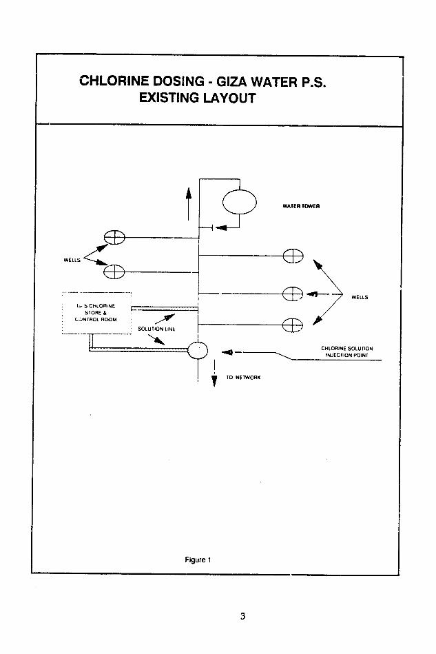

GIZA
POTABLE WATER SUPPLY
10 October 1991 Awsim Markaz
Purpose
PW 72 To follow up on the visit of 29 September to evaluate the effect of chlorinating local water systems in Awsim Markaz
Observations
Special TA is being provided to assist the governorate with the installation of 12 chlorine units to be installed usng fourth-cycle funds Six existing units are in service and some of these are being evaluated before the new units are installed
Water samples taken fro the systems supplying Bertes and Monshat El Qanater were tested for chlorine residual and bacterial contamination This is the second set of samples taken at Bertes on the first occasion no chlorine residual was detected at the end of the network
The results of tests showed excessive chlorine residual in the networks of both villages Bacterial tests by the Millipore method showed 9 fecal coliform100 ml at Monshat E Qanater well All other samples were free of fecal coliform
At Bertes the dose rate was 1 kghour of chlorine gas reduced to 06 kghour after the first two hours The chlorine dose rate at Monshat El Qanater was 06 kghour The pump rate at both stations was 40 1second yielding a chlorine dose of between 4 to 7 mgl (rather high)
Follow-up
Uoe the data collected to finalize the special report on the use of gas chlorinators in Giza Governorate
14
APPENDIX B Chemistry of Modern Water Chlorination
15
HOLI ITD GROUP
Chemistry of Modern Water Chlorination
by AT PALIN BSc PhD FRIC PAIWE
Reprinted from WATER SERVICES January amp February 1974 Volume 78 Numbers 935 amp 936
Technical Publication BRA353
DISTRIBUTED BY
WALLACE ETIERNAN LIMITED MEASUREMENT amp CONTROL
PRIORY WORKS TONBRIDGE - KENT TN1 1 OOL ENGLAND Teko TONORIDGE354481ISTDCoO7321 Tt MI C WALTIERNAN TONSAIDGE
WRIGHT AFRICA PO BOX 93033 - YEOYILLE
2143 JOHANNESBURG SOUTH AFRICA16
Chemistry of Modern Water Chlorination By A PALIN BSc PhD FRIC PAIWE
This article which will be published in two parts takes the form of a review of the present state of our knowledge on the use of chlorine for the disinfection of water There are four sections an introduction the chemistry of chlorination disinfection by chlorine and chlorinashytion of wastewaters and industrial waters
I Introduction IN TRE VAST MAJORITY of cases where disinfection of water is required whether for public supply or in the swimming pool the process will involve the use of chlorine in one form or another If properly applied the chlorination process is able to provide other benefits such as the removal of colour the correction of tastes and odours and the suppression of unwanted biological growths Chlorine also plays an important role in the treatment ofindustrial waters and wastewatersThe pste ts psuitableThe purpose of this paper itoptecnt a guid- to the
chemistry of modern chlorination przsses In the control of these processes the most essential feature resides in the regular testing for the level of hl-rine in the water that is the residual chlorine in or I i the desired anti-microbial concentration mav untained without producing such undesirable relulr -hlorinous tastes and odours in drinking water or unpl inst bathing conditions inswimmingpoois Theseunwan -ffectsmavarsenot onlyfrom excessive concentration-1 hlorine itselfbutfrom the production of obnoxious chlr -npounds ofammonia orof nitrogenous organic matTrr Tl 1tlise to the full all the
benefit- now afforded by modern chlorination techniques and to eliminate all those problems associated with inshycorrect control and application the importance of a reliable and yet imple system of testing such as the DPD method i 2 3 cannot be over-estimated
The great advances that have been made over the past two or three decades in our knowledge ofwater chlorination chemistry have in fact resulted from the development of
analytical techniques It is now fully recognisedthat the apparent complexities of chlorine chemistry as
exemplfied for instance by the breakpoint phenomenon could not have been elucidated without some means of determining the nature and the amounts of the different types of residual chlorine compounds involved in the e various reactios that take place at relatively ninute concentrations in ater The behaviour of such comshypounds and especially their ability to react both among themselves and vith free chlorine provided a rewarding field for continuing exploration mad_ possible by the analytical methods that became availa ic
II The Chemistry of Chlorination A-History
Towards the end of the nineteenth century there were several instances of the use of chlorine compounds for the disinfection of water and with increasing experience there came an appreciation of the effective es of the treatment The introduction of water chlorination as a continuous process occurred both in England and in America soon after the turn of the century The develop-ments that have taken place ince that time have been outlineda as follows-
1905-1l5 A period mainly of hypochlorite disinfection coupled with a certain amount of scepticismand prejudice against chlorination
1915-1925 The evolution of gaseous chlorination andcontinued education of the public
1925-1935 A time of very great interest in chlorination Bacteriai nd taste problems were vrvmuch to the fort with the use of chloamie being much advocated
1935-1945 A period of greater flexibility in chlorination methods with increased ise of semi-auto-matic apparatusmari aparaus100
1945-1955 Advances in the understanding of basic principles coupled with much fundamental research Greatly improved methods of control of chlorination
This last period also saw the development of chlorine
dioxide treatment of water Since 1955 attention has been concentrated on the refinement of test procedures for the more accurate determination of residual chlorine comshypounds so that every requirement of treatment control could be met to ensure optimum results under all conshyditions Even in ituations where full laboratory facilities are not available the modern types of test-kit provide complete reliabdity with maximum convenience and sipliciry
B--Forms of Chlorine 1 The Meaning of Available Chlorine
The concentration of residual chlorine is alwaysexpressed in terms of available chlorine no matter in what chemical form it might be present It is clearly advantageous to have a common yardstick for comparing one form say hypochlorous acid against another form sav monochloramine The same also applies to the chlorine
Compounds used in water treatment such as for example sodium hypochlorite or chlorine dioxide The available chlorine content of chlorine itself is by definition taken as
ChiefChemist Newcatle and Gaterhead WaterCompany Laboratory 7TcIle Newcastle upon Tyne NE 159DT
17
The concept of available chlorine is to some extent an Table 1 Chlorine contents of commercial products artificial one but itremains the standard form of expression for the strengths or capacities of chlorinating chemicals as Quantity well as for the doses in which they are applied and for the eqwvalent to Ilb residues which remain in the water Any chlorine that Reagent of chlorine gas finally appears as chloride the final reduction productrepresents a complete loss of available chlorine Chlorides Chlorine gas I lb
such as sodium chloride have zero available chlorine The test that determines whether or not a comp-itnd High test hypochlorite tcalcium hypochlorite)
has available chlorine is the ability to react with potassium 65 to 70 available chlorine 1 5 lb iodide (KI) in acid solution to release free iodine (I) The percentage amount of available chlorine is obtained by Chlorinated lime (chloride of lime)
30 to 35 available cbloriuw 30lbcomparing the amount of iodine so liberated with the amount of iodine liberated from the same weight of Sodium hypochlorite chlorine When chlorine reacts with potassium iodide 15 available chlorne 07gal under these conditions each gram liberates 36 g of iodine 10 available chlorine 10ga It is thus necessary only to calculate from the reaction that 5 available chlorine 20 gal would occur between a chlorine compound and acidshyiodide the amount of iodine liberated by one gram of that compound This figure is then divided by the above 36 and multiplied by 100 to get percentage available chlorine heavv as water Chlorine sproduced commercially fiom
While in actual analytical practice one would avoid the heaiu aswtr Chornele roduce com ercillylfiouse of hydrochloric acid (HCI) in this determination (since sodium chloride by an electrolytic process and is supplicdt eunder pressure in cylinders cf up In 150 lb net capac~ty
it may contain traces of free chlorine as impurity) it is so that at temperatures of about 65 F 80filled is simpler for our theoretical exercise to use HCI rather than occupied by liquid the remainder being gas Largerintroduce another acid radical such as acetate in the ocuidb lqith reanrbeggsLgrequations containers of up to I ton weight are also used and for stillIn the case of hypochlorous acid the reaction would be larger quantities tank cars are availableshown thus- The rate of flow from a container depends upon thecylinder or tank pressure which in turn is governed by the
HOCI + 2KI + HCI 2KCI + HO + I temperature of the contents as shown in Fig 1
From a consideration of molecular weights we find that 525 parts by weight of HOCI yield 254 parts by weight of iodine therefore
I g hypochlorous acid - 254 525 484 g iodine
Percentage available chlorine 0
484 36 100 - 135
It is apparent that some chlorine compounds can be rated as having more than 100- of available chlorine when their capacities are compared on this basis To take chlorine dioxide as a somewhat more complicated example this would reactshy2CIO 4- IOKI + 8HCI = IOKCI + 4HO + 51 Do
from which it may be calculated that 1 g of chlorine dioxide produces 941 g of iodine therefore 150
Percentage available chlorine z 941 36 100 - 261 In these theoretical calculations it has been assumed that
the chemicals in question are 100 pure Thus taking sodium hypochlorrte for example the pure form (which being highly unstable is not commercially available) would have an available chlorine content of954 The commershycial sodiuni hypochlorite or liquid bleach as manufactured - _ c shy
contains 12 to 15 available chlorine which represents a dilution of about 7 times As is the case with many of the -S compounds used for chlorination purposes there is a Temnperature-essute cur - for1aO chlorne gradual loss of strength on storage and this also may be gauged on the same available chlorine scale
In assessing the costs of chlorine from different commershycial products a knowledge of their available chlorine contents The pressure provides no indication of the weight of the is essential as wll be seen from Table 1 contents and will remain steady so long as the temperature
is steady right to the final stages of emptying when all liquid has been gasified At this point the pressure drops
2 Gas rapidly if withdrawal of gas is continued The amount of chlorine used over a period is determined by weighing the
Chlorine gas is greenish yellow in colour Liquid container at the start and again at the end chlorine which is obtained by compressing the gas until There is a limit to the rate at which chlorine gas may be it liquefies is an amber coloured oily fluid The gas is drawn from a container since the process of converting about 2 times as heavy as air Thus in the event of a leak liquid chlorine to gas (like the boiling of water) requires a it will sink to the floor The liquid is about IAtimes as continuous flow of heat from the outside of the container
18
the inside If this flow of heat cannot match the rate at Vich the liquid chlorine is being evaporated heat will be stracted from both the container and its contents thus
iving a cooling effect to such an extent that eventually ost will form on the outside The gauge pressure will be arrespondingly reduced The dependable maximum continuous rates of with-
rawing gas from containers assuming the room is at ormal temperature and air circulation is reasonably good e as follows-
100 to 150 lb cylinders 1kit 175 lb per hour I It
1 ton containers 15 lb per hour
1 ton containers (with evaporator) 40Q lb per hourUo44 tW
Two or more evlindcrs may crlamnflnddischrgedrsltneosly so asnto o a in dnd discharged simultaneously so as to obtain an increased ate of discharge With such an arrangement it is necessary o ensure that all cylinders are at about the same tempera-ure Should one cylinder be much cooler than the others
Smight happen when a new cylinder is added to the nanifold there would be a flow of gas from the warmer nd consequently higher pressure container to the cooler oittainer in which reliquification would occur leading to he dangerous condition of being completely filled with iquid chlorine
Chlorine cylinders normally stand upright so that only hlorine gas is drawn off To obtain in increased discharge ate from the larger size of container the chlorine may be eli vered in liquid form to an evj orator
Dry chlorine gas is not corrosive to most common metals so that the use of iron cylinders and iron tubing is satis-factory If the gas picks up moisture for example when leaks occur into moist air and also when dissolved to produce chlorine solution for application to the water it becomes very corrosive The solution must therefore be conveyed in such materials as glass hard rubber or silver Solution-feed is the usual practict sshere the solution is prepared by first dissolving the gas in a supplementary flow before adding to the main flw This facilitates rapid distribution and uniform tnirv - the chlorine in the water and avoids the risks of cotrosion or undesirable side reactions resulting from high local concentrations at the point of application
3 Solutions These contain chlorine in the chemical form of hypo-
chlorite and are usually prepared from chlorine and caustic oii thus givinv sodium hypochlorite Such solutions are
alkaline and this helps preserve them For fresh solutions the available chlorine content can be up to 15 by weight but with storage there is a gradual loss of strength so that wthin 3 or 4 months up to half the available chlorine may be lost In practice the solution may require dilution to provid more onnient application with solution-feed dosing euipmcit
Sodium bvpochlorite solution is sold under a variety ot trade names and packing is normally in glass earthenware ar polythene carboys or in rubber-lined drums Storage should be in cool darkened areas Care is required in handling in view of the corrosive nature ofhpochlorite olutions and the consequent risk if hzrmfultontact with
eyes and skin in the event of accidental spillage
4 Solids
In addition to the solutions which contain sodium iypochlorite solid hypochlorites are available generally in he form of calcium compounds although lithium hypo-chlorite (35- available chlorine) may find some application or instance in laundries and in swimming pools but riot or potable water supplies
One of the best known solid hypochorites is chlorinated lime also termed chloride of lime or bleaching powder The essential constituent is calcium oxychloride which is decomposed by water to produce calcium hypochlorite The excess lime present in chlorinated lime is insoluble these suspended solids should therefore be allowed to settle out from the solutions before use Alternatively the chlorinated lime may be added direct to the water as a powder
Fresh chlorinated lime has about 33 available chlorine content but loses strngth fairly rapidly on storage unless conditions are cool and dry when the drop in available chlorine content may be no more than 1 a month
Containers must be made of corrosion-resistant material and kept carefully closed
superior form of solid hypochlorite known as HighTest Hypochlorite is available This is solid calcium hypochlorite produced as a free-flowing granular material or as tablets The available chlorine content is up to 70 Under norma storage conditions only 3 to 500 loss a year is claimed thus giving a much more satisfactory shelf life than chlorinated lime The calcium hypochlorite granules dissolve readily in water the tablets dissolve more slowly which is advantageous where a fairly steady rclease of chlorine is required over periods of up to 24 hours
5 New Products
Much attention has been paid in recent years to the development of newer types of chlorine compounds with special reference to their application to the treatment of swimming pool water
Increasing use is now being made for example of the chloroisocyanurates which are compounds of chlorine and cyanuric acid Their use arose from observations that cyanuric acid acts as a chlorine stabiliser reducing the chlorine loss associated with the interaction of chlorine with ultra-violet light
The release of residual available chlorine in the form of hypochlorous acid is governed by the equilibriumshy
chloroisocvanurate + water
cyanuric acid + hypoeblorous acid With continued treatment the wcentration of the
cvanuric acid itself will gradually build up thus causing the above reaction to proceed from right to left to maintain the chemical balance The concentration of hypochlorous acid could therefore become very much reduced so that to avoid this some control should be exercised of the cyanuric level by regular testing The optimum level is tited to be about 30 mg I with a top limit of 100 mg I The nriial entry of make-up water to a pool may be
adequate to keep the cyanuric acid oncentration within the desired range by diiution but should the level become unduly high it may then be necessary to revert temporarily to hvpochlorite treatment
Chlorine dioxide is another chlorine compound which is finding use in swimming pool treatment In the water supply field it has been available for twenty fiv years or more as an improved means of controllirg unpleasant tastes and odours The compound is produced on site bymixing strong chlorine solution as discharged from thechlorinator with a solution of sodium chlorite when the
following reaction occurs-Cl + 2NaCIO - 2NaCI + 2CO
Alternatively in smaller installations the chlorine dioxide may be generated by mixing solutions of sulphuric acid sodium hypochlorite and sodium chlorite On the basis of its available chlorine content its oxidising capacity is about 2 times that of chlorine but it would be incorrect to claim that it therefore has 2 times the oxidising power
19
or potential of chlorine In many reactions for example remaoval of colour from water it is considerably weaker than chlorine
Chlorine dioxide treatment is generally more costly than normal chlorination It differs chemically from chlorine in being inert towards ammonia and consequently does not produce chloramincs and similar combined chlorine com-pounds This is advantageous especially in swimming pools where such compounds if their concentration becomes unduly high can be very objectionable to bathers by causing irritation of eyes and mucous membranes Trichloramine (nitrogen trichloride) can be particularly troublesome con-under certain conditions of chlorination but
dioxide treatment Preparationsnot with chlorine taining so-called stabilised chlorine dioxide have become available for a variety of disinfection purposes including swimming pools
In swimming pool treatment some use has been made of diHalo a product which has the chemical name N-bromo-
When added to water thisN-chloro-dimethyl hydantoin compound liberates both chlorine and bromine and gives conditions which are claimed to be more pleasant to bathers The application of the authors analytical methods to an examination of the active residuals produced in the water indicates that the treatment is best regarded as a bromination process since free bromine is found to pre-dominate over free chlorine
C-Chlorine Dissolved in Water In appronchin the chemistry of chlorination it is
necessary to start by considering the reactions of chlorine i pure water In the first place the chlorine rapidly hydrolyses to form hydrochloric acid and hypochlorous add thus-
CI plusmn 11O - IICI + HOCI
The hyrochlsrou acid then partly dissociates to give hydrogen ions and hypochlorite ions-
IOCI - H- + 0C-
The three forms of available chlorine involved in these reactions namely molecular chlorine C12 un-ionised hypo-chlorous acid ItOCI and hypochlorite ion OCI exist together in equilibrium Their relative proportions ire determined by the pH value and temperature Furthermore the proportions are the same for any set of conditions whether the chlorine is introduced as chlorine gas or as a hypochlorite
i- 2tcr chlorination pH is the all important factor 0c t relative proportions as shown in Fig 2
nIAnt that as the pH falls below 2 the predominant ior- Between pH 2 and pH 7 the equilibrium is nsc Lnmgly in favour of IlOC1 At pH 74 HOCI and OC- arc ab-ut equal while above this increasing propor-tions of OCI- ire present At more than p11 95 all the available chorinc i present in this form
Chlorine vhich i present in water as Cl HOCI or OC- or in any mixture of these is defined as free available chlorine Clearly at the pH ranges encountered in water chlorination free chlorine will consist of a miature of HOCI and OCI-
It will be apparent from the first equation that in addingchlorine to water a proportion of hydrochloric acid (h CI)is produced which will reduce the alkalinity The amounts involved are so small in practice however that except in very soft waters having little buffering capacity (ie inbuilt resistance to P-I change) or in cases where very high chlorine doses are involved the resulting effect upon the pH of the water is inappreciable In fact the application of chlorine to a water in a dose of I mgl will reduce the alkalinity by approximately I mgI which for example in
00
9O 90
so OCI
70 shy7
u 0 bO
ltz 50 HOCI
- 40 x
z 30 R
20
u
aI0 -2
gt 0 I 2 3 4 5 b 7 8 9 IC
pH VALUE Fg 2 Effect of pH value c form of free avalable chlorine in
Water
a swimming pool of 100 to 200 rag I alkalinity would be quite insignificant
D-Breakpoint Reactions
Having considered the behaviour of chlorine when dissolved in pure water it is necessary next to examine in what way the reactions are affccted by the presence of
those impurities which may be encountered in the chlorinashytion of natural and polluted waters It is now established 6
that the most profound influence upon the chemistry of water chlorination is exerted by ammona the presence of which is generally associated with pollutive matter
By simple substitution reactions it is possible to proceed as follows-
NHI --- NHCI -- NHCI --- NC) 3 ammonia monochloramine dichloramine nitrogen
trichloride Generally the lower the pH and the higher the chlorine
ammonia ratio the greater the tendency to produce the more highly chlorinated derivatives But with increasing chlorine ammonia ratio secondary reactions occur the studv of which has produced results of the greatest possible signi ficance The rate of these reactions depends upon pH and is at its maximum in the pH range 7 to 8
For our present purpose it will be unnecessary to explore the whole range of possible reactions under different conditions but to concentrate upon the normal pH range
of drinking water and swimming pool water here we find that the product of the reaction between chlorine and ammonia is almost entirely monochloramine The time taken for this to form is very short probably less than one minute and the reaction may be shown as olows-
NH3 + C12 = NH 2CI + HCI From this reaction it may be calculated that I part by
weight of ammonia-nitrogen requires 5 parts by weight of chlorine Thus ignoring any loss of chlorine from other causes we can say that so long as the dose is not in excess
20
5 times the ammonia-nitrogen in the water all the s orine will go Lowards producing monochloramine E But if more chlorine has been added than is required for 1 4 is rapid initial reaction a continuing oxidation reaction F
-curs at a rather slower rate eventually producing mainly o itrogen as follows- so0
2NHCI + Cl = N + 4HCI
Whenever the chlorine dose exceeds the ammonia- - 20 trogen in the water by more than 5 1 (again ignoring ci Ieeffect of other chlorine-consuming substances) this type NMCI
reaction will occur resulting in a loss of available o ilorine There is usually some appearance of dichloramine t NCI
id nitrogen trichloridcin the zone corresponding to the 0shy
ilorine dose having gone beyond the 5 1 ratio but the 0 0o O 4o 50 50 70 80 -t result as the chlorine is further increased eventually )rresponds to the following overall equation- 7-- - e t 1
6HCIN ++ 3C2NHj
From this we can calculate that the amount of chlorine equired to oxidise one part by weight of amir2rii- so titrogen is 76 parts by weight and at t- point los of shyvailable chlorine would be at a maximum It so happens a
hat because of certain side reactions leading for instance 4o
o the formation of trace amounts of nitrate the observcd 0
atio is a little higher at appoximately 83 1 In practice C-o ne must allow for other substances in natural waters so that the usual ratio for thi N14C1apable of absorbing chlorine 2
iarticular point now called the breakpoint is around o 0 1 but of course for grossly contaminated waters it
hiay be 25 1 or even higher c12
If a series of aliquot portions of a water sample containing _0 NCoI lmmonia is treated with progresively increasing amounts Df chlorine and the residual chlorine values after a period af contact are plotted against the corresponding chlorine 0 0 0 o0
DOSEloses a hump and dip type of curve is produced known as CHLORINE P
the breakpoint curve This curve has three distinctive features which we can now relate to the chemistry so far aa--amp j
-onsideredshy
1 an initial rise of residual chlorine in which zone the compound present is chloramine
2 a secondary fall in residual corresponding to the un- sc0 stable zone in which there has been an excess of t chlorine over and above that required to give complete 40
formation of chloramine Here this excess has entered o into mutual decomposition reactions with the initially formed hioramine 30shy
3 a zonc characterised by a final rise in residual chlorine corresponding to complete oxidation mainly to nitrogen 2to Here the continuing addition of chlorine to the water NCnc gives a pro rata increase in the residual 0 iTccc CI
The minimum point between stages 2 and 3 is called the N 4CLN C oreakpoint and the addition of sufficient chlorine to reach
[beyond this point -rovides many advantages The relation o 40 50 6C C SC
ofthe breakpoint in chlorine-ammonia reactions to pH oC 20 C0
is shown in Figs 3a b) and (c c-Cp t DOSE 4S
In addition to ammonia other nitrogenous compounds e - r - ctre at H t can produce breakpoint turves in which the hump and dip 1nt q on a 7I (v) is clearly distinguishable although generally not so marked as in the case of chlorine and ammonia All may be explained on the same basis
Apart from the early stages of the breakpoint reactions Recognition of these two forms of residual chlorine is of when free chlorine may exist in the water for a time in the greatest importance since the chemical bacteriological conditions corresponding to the dip portion of the curve and virucidal properties of free chlorine are vastly superior the vital distinction of importance in water chlorination is to those of combined chlorine Therefore for maximum that before the breakpoint the residual available chlorine safety in the production of germ-free water it is essential to is present in the form of chloramines and related compounds chlorinate to the point of establishing free chlorine And and this is termed combined chlorine After the break- where because of the presence of animonia-type impurities point it is present as free chlorine which as we have seen is there is some initial appearance of combined residual a mixture at normal pH values of hypochlorous acid and chlorine compounds chlorination should be adequate to hypochlorite ion ensure that by continuing reaction with them their conshy
21
centration is reduced to a minimum that is to say the water must be chlorinated to beyond the breakpoint since it is here that the residuals are substantially in the form of free chlorine That the treatment has been properly carried out can only be established by using test procedures capable of determining free chlorine separate from corn-bined chlorine
A disadvantage of breakpoint chlorination is that the free chlorine residuals produced in the water may unless the pH is fairly high oe accompanied by traces of nitrogen trichloride In ome situations this ha proved a problem in view of the objectionable chlorinous-type odours thereby imparted to the wvater It may then be necessary as a final stage to dechlorinate completely itih a further stage of chlorination or ammonia-chlorine as a final treatment
Tra-cs of nitrogen trichloride may also be encountered in a swimming pool s especially if tle pH value is alloweJ to fall In indoor pools this could cause complaints from bathers of eve irritation since the volatile nature of NCI facilitates its escape to the ationespherL Consequently the atisactory application of modern chlorination tcchniques to svimming pools requires not only differential testing for free and combined chlorine but a measure of pH and alkalinity control
E-Modern Chlorination-Definitions and Classification
Against this background of chemistry we may now set down the definitions which are fundamental to modern chlorination
Free azalable residual chlorine is defined as that residual chlorine existing in water as hypochlorous acid and hypochlorite ion
Combined available resiual chlorine is defined as thit residual chlorine existing in water in chemical combination with ammonia or organic nitrogen compounds
The chlorine demand of a water could be regarded as that portion of the applied chlorine dose which has been converted to non-available chlorine that is by definition not able to liberate iodine from an acidified iodide solution and similarly giving no response in the usual residual chlorine tests For a precise definition of chlorine demand however it is necessary to specify the chlorine dose the time of contact the temperature and the nature of the residual aimed at whether free or combined available chlorine
In view of the general acceptance of the superiority of free residual chlorine compared with combined residual chlorine it is evident that the preferred definition applicable to the majority of cases is as follows
Chlorine demand is defined as the difference between the amount of chlorine added to water and the amount of free available chlorine remaining at the end of a specified contact period
This definition may thus be related to the breakpoint curke and corresponds to the chlorine required to reach the breakpoint plus such further amount as may be required to produce the desired level of free residual chlorine beyond the breakpoint
It will be appreciated however that man) waters may have a chlorine demand due to non-nitrogenous organic matter or oxidisable inorganic substances with relatively insignificant amounts of ammoniacal or nitrogenous impurity In such cases the chlorine dose residua curve will not exhibit the typical hump and dip of the breainoint curve but will remain at a low level during the stage of satisfying the demand after which free residual chlorine will appear and show the pro rata increase with increasing dose The common feature is that sufficient chlorine is applied
to produce free as opposed to combined available residual chlorine
The modern approach to the classification ofchlorination processes is based upon this important distinction between free and combined chlorine thus giving two main types of process These are termed free residual chlorination and combined residual chlorination Ir applying free residual chlorination to some water -upphies it may be desirable either because contact time i very klort or pollution loads are variable to operate at Ievls of free hlorine so high that dechlorinaLion is sUbsequcntly required before delivery to the consumer This process thichi knov n as supershychlorination and dechlorination mav then bc applied without particular rclfcrence to a breakoint the aim being to enurec that ample free chlorine is produced
In other circumstances vhere there is adequate time for disinfection to be achieved there may bc ome advantage for example lessened risk o producing ome types ot Caste and odour in working with combined chlorine residuals produced by react between chlorine and nitrogenous constituents naturally present in the water imple or marginal chlorinationgt Alternatively amiona may be deliberately ipplied usually before the chlorine as part ot the process Thloramine or ammonia-chlorine treatment
Thus the system of classification may be et doswn as in Table 2
Table 2 Classification of chlorine processes
Chorination
re Residual (mt md Rsidual
[treakpoint Superchlormation Simple Ammoniashy
chlorination and
dechlormation or marginali chlorination
chorme treatment
It is possible of course to introduce variations to suit particular requirements for instance an operator may apply free residual chlorination through his plant with final conversion to combined residual by applyingammonia) to maintain chloramine-type residuals rather than free chlorine in the distribution network Again a novel use of the breakpoint reactions may be made in which ammonia takes on the role of dechlorinating agent
Whatever modification of chlorine treatment is used however the results obtained under any given conditions must always depend upon the nature and amount of the residual chlorine produced in the water The production of residuals of known composition by suitable control of chlorination has been made possible by the methods of chlorine residual differentiation now available
Refercnces 1 Department of the Environment Analysis of Raw Potable and
Waste Waters London 1972 2 APHS AWWA and WPCF Standard Methods for the Examinashy
tion of Water ampWastewater 13th Edn New York 1971 3 German Standard Methods for the Examination of Water
Sewage and Sludge 3rd Edition 4 Waddington A H Proc Soc Water Treat ampExa 4 71
1955) 5 Palm A T J Itt Water Enqr 2 61 1948
6 Palin A T Wat amp War Ernng 54 151 189 248 1950)7 Williams D BJ AWWA 41 441 (1949) 8 Palin A T Proc Nat Assoc Baths Superintendents 20 78
(1950)
22
IXL Disinfectionby Chlorine
A-The Effect of pH WHILE THE PRESENT PAPER is primarily concerned with the chemistry rather than the bacteriological aspects of water chlcrination it is necessary to have regard to those physicaland chemical factors which influence the bactericidal and virucidal power of chlorine
From Fig 2 (see Water Services January 1974) it may be seen that within the range pH 6 to pH 9 free available chlorine comprises a mixture in varying proportions of hypochlorous acid and hypochlorite ion With pH risig over 6 the proportion as HOCI declines from virtually
r1001 down to almost zero at pH 9 The activity o HOCI as a bactericide is greatly superior to that of the 0Cl- ion being something like 80 times more powerful Consequently it may be concluded and practical experience bears this our that in free residual chlorination the higher the pH value the less active is the residual because of its lower proportion of HOCI Apart from the desirability of distinguishing free chlorine from combined chlorine in the residual chlorine test there would seem therefore also to be a need to differentiate between these two forms of free chlorine HOCI and OCI- This has not however been considered necessary in practice nd usually the recom-mendation has simply been - work to a higher free chlorine residual a( the higher p11 Ilucs Some have taken this further by specifying the lc- offree chlorine residual for different PH values to ensur ih3tat all times the same amount say 1 mg I of HOCI i prscnt
Table 3 shows the levcl k-l I chlorine required to achieve this result
Table 3 Free chlorine -it different pH values
pH Total Free Residual Chlorine Value to give I mg I HOCI
20C
60 10 1 0 65 11 170 12 14 75 17 22 80 32 43 85 80 120 90 220 400
The extensive work that has been carried out on the bactericidal efficiency of free available chlorine has provided ample confirmation of the retarding influence of high pH Possibly the most comprehensive studies were those conducted by the US Public Health Service from 1943 to 1948 9 1owhich also demonstrated that the killing power of chloramine diminishes with increasing pH
B-Effect of Temperature and Time of Contact
value are combined the reduction in the efficiency of free chlorine and chloramines is very marked
These factors have an important bearing therefore on the time of exposure necessary to achieve satisfactory disinfection Un~er favourable conditions the contact time required with free available chlorine may be only a few minutes combined available chlorine under the same conditions might require one or two hours Whatever the conditions however the final test of disinfection resides in bacteriological examination to ensure that the treated water complies with recognised standards such as for example those of Report No 71 The Bacteriological Examination of Water Supplies
C-Nature of Residual Chlorine andMinimum Safe Levels
In the studies by the US Public Health Service from 1944 to 1948 a comparison was made between the bazterishycidal activities of free chlorine and chloramine The experiments were so conducted that the chloramine would be preformed in the water befor- the addition of the bacterial suspensions which is not truly representative of actual water treatment practice Nevertheless the conshyclusions were highly significant in showing that to obtain
complete destruction of bacteriashy
(a) with the same exposure period-about 25 times as much chloramine as free chlorine was required and
(b) with the same amounts of residual-iabout 10) times the
exposure period was required with chloramines as with free chlorine
Data secured in these studies using 10 minutes contact with free available chlorine and 60 minutes contact with
combined available chlorine provided he basis for recomshymended minimum safe residuals In 1956 the US NationalResearch Council 12 re-analysed the Public Health Service data and submitted revised recommendations based on a 30 minute exposure period At the same time additional recommendations were made in connection with minimum cysticidal chlorine residuals These later recommendations form the basis of Table 4
Table 4 Minimum cysticidal and bactericida r-qidual(after 30 minutes contacto mg l
Free Chlorine Combined Chlorine pH Bactericidal Cvsticidal Cysticidal Bactericidal
0-2jC 22-25C 2-5 C 0-25C
60 02 20 75 20 70 02 25 100 25 80 02 50 200 3090 06 200 700 35
The bactericidal power of both ftee chlorine and chlorshyamines decreases with falling temperature In any situation It may be assumed that in practice the performance of where the effects of lowered temperature and high pH ammonia-chlorine treatment where chloramine formation
23
occurs in the water itself rather than being preformed will be considerably better than is suggested by the above figuxs This is explained by the fact that the reaction between chlorine and ammonia is not instantaneous but requires up to I minute or thereabouts for completion the actual time being dependent upon pH and temperature During this period the proportion of unreacted chlorine although decreasing quite rapidly nevcrtheless retains the bactericidal power of free available chlorine As a result there is a short initial period in ammonia-chlorine treatment
during which an enhanced rate of bacterial kill may be expected Upon completion of the reaction between chlorine and ammonia the rate falls to the very much lower level characteristic of combined chlorine Thus even if full allowance is made for the initial period of rapid action in ammonia-chlorine treatment the differences in the bactericidal and other properties of free chlorine and combined chlorine remain so marked that modern trends can only be more ani more towards free residual chlorination
IV Chlorinationof Wastewaters and IndustrialWaters
A-Introduction Various tests have been devised for the pracdcal assess-
ment of the pollution that results from the discharge of sewage effluents and similar wastewaters to streams and rivers Of these one of the most important is the test for Biochemical Oxygen Demand that is the BOD test designed to provide an indication of the amount of oxygen required for biological stabilisation of the river water after it has received the polluting discharge This test involves the measurement of the amount of dissolved oxygen absorbed by the sample under controlled conditions normally after 5 days in the dark at 20C and simulates the process f aerobic degradation that occurs in the receiving water The BOD test is applied to sewage sewage effluents and river waters and provides a reasonably good indication of the load of impurity represented by oxidisable conituents
The information afforded by the BOD test is supple-mented by the results of other physical and chemical determinations covering a wide range including pH suspended solids ammonia nitrite and nitrate perman-ganate value chemical oxygen demand (or dichromate value) surface active agents and constituents such as cyanides and phenols known to be toxic to fish
It is generally appreciated that no matter how satisfactory a sewage effluent may be as gauged by such analysis it remains bacteriologically impure with possibly a high proportion of pathogenic organisms The risks to public health associated with the disposal -f such wastewaters make it imperative that adequate protection be provided to water supplies bathing beaches and shell fish growing areas Recognition of the need for disinfection has led to the use of chlorine as the most practical and efficient means available for this purpose Although originally introduced principally for odour control for which it remains an effective remedial measure the present position in America is that chlorination finds its primary use as a disinfectant in which capacity it has become established as an integral part of wastewater treatment processes In the UK however the chlorination of effluents to be discharged to surface waters has not generally been so favouraoly regarded
In addition to disinfection and odour control the chlorination of wastewater serves a number of other useful functions of which the following may be mentioned-prevention of septicity control of slime and insect life on trickling filters control of activated sludge bulking and restriction of bacterial slimes and fungal growths in effluent channels and pipes
In industry water is used for a variety of purposes of which cooling probably represents the major proportion in terms of quantity If supplies are adequate a once-through
system is usually the most economical although in some circumstances it may pay to install a circulating system either open or closed
In once-through systems the water used is drawn in many cases from surface sources Such natural supplies contain a variety of living organisms which can cause trouble from biological slimes algae and growths of iron bacteria The most economical control method is to apply chlorine intermittently as a shock dose of short duration Difficulties due to slime and algal growths are also to be expected in open circulating systems and here again chlorination provides the control measure in widest use
Other important applications of chlorination are to be found in the food industry and papermaking In general the uses of water in industry are so varied that treatment methodt must be geared to suit particular applications However in any situation where problems arise from unwanted biulogical growths such as slimes or bacteria it is frequently found that chlorination is relied on to provide the desired control
The effluents from sewage treatment plants serving industrialised communitis contaii in varying quantities the host of chemicals that modern industry either uses in its various processes or discards as the unwanted end products of its activities Treatment of such effluents may pose special problems especially where discharge is to rivers subsecouently used as sources of public water supply Chlorination oftn assists in the bre-kdown of these harmful pollutant6 or thtir conversion to less toxic products
B-Chemistry of Wastewater Chlorination
While chlorine reactions in wastewaters are influenced by factors not usually encountered in the potable water field there is a fundamental similarity especially where nitrogenous compounds are concaied The organic nitrogen compounds encounterd arc however more complex and upon chlorinatica yield a variety of organic chloramine residuals of doubtful germicidal value To some extent the various reactions with proteins and protein degradation products may be accounted for by a conshysideration of the reactions between chlorine and amino acids in which it has been shown that mono- and dichlorshyamino derivatives are obtained6 Such compounds are capable of responding to residual chlorine tests and to that extent they are to be regarded as a form of combined available chlorine although uncertainty as to their germicidal value has led to their being relegated to the class of nuisance residuals These chloramino compounds are of varying stability in the absence of free chlorine Decomposition is enhanced by excess cblorine so that a breakpoint effect is obtained although the chlorine doseresidual curve does not
24
APPENDIX C Exampies of Chlorine Dosers Using Powdered Chlorine
25
THE VWMLL-Lb I I IbIMNAN I I PUBLICAIION BP80051
SELF POWERED CHEMICAL DOSER RECOMMENDED ARRANGEMENTS FOR THE
TREATED WATER SERVICE TANK Whilst Wallace amp Tiernan offer the following (5) Similar to fig4 but ball float movement is arrangements as a guide to I stalling a Self within a small chamber with an additional valve to Powered Chemical Doser it should be realised provide rapid action of the inlet valve to the SPCD that much of the advice given will depend on the (6) The optimum arrangement where he tank is site conditions and the available water source- baffled to provide two sections and so give a (1) The simple instaiation where water flows by contact time to allow disinfection to take effect gravity into the SPCD and passes after treatment via tiie syphon into the service tank Notes The Treated Water Service Tank
(2) Where it is necessary o install the unit - should be of a capacity slightly greater than above the source the water may be hand pumped that of the SPCD mixing tankvia the SrCD into the service tank - large enough to demandcover during any(3) Where electricity is available and in similar period when the flow from source may reduce circumstances to fig2 stopstart control of input may be achieved with the use of a pump - should have levels for ball floats or probes with level controls established so that cycle is initiated whilst thereis still enough water for draw-off (4 Another frrm of level control with the aid of a conventional baUlfloat valve - fitted with a removable cover
o GRAVITY FLOW FROM SOURCE If water from source exceeds usage - treated water may flow to waste via overflow In service tank
O HAND PUMP-- Were no electricity 1 S available water can be hand pumped This method though least favoured ensures that only treated
TANK COVEwater is used i - - -- -J TANKC-ER
OELECTRIC PUMP- J with level controls I High and low probes In the service tank provide stopstart OVERFLOW control of water to the SPCD TO SERVICE_ --~~~ _------ _ SIGHT GLASS (PLASTIC TUBE) Optional
TAP Optionamp SUPPORT STRUCTURE
26
- ---
- - --
BALL FLOA1 CONTROLLED OPERATION Untreated water flowing into the SPCD is conshytrolled by the level In the service tank This conventional form of ball float contreir is suitable where draw-off Is reasonably hlh and fairly consistant If small amounts of treated water are taken from the service tank this method may result in unwanted additional dilution of the dose
FROM
1-1 RAPID ACTION SALL FLOAT CONTROL Movement of the ball flat isOVERFLOW confined to a small section fitted with an additional )
valve to provide a snap action thereby overcoming the above problem SRITO SERVICE
0 OPTIMUM ARRANGEMENT Where site conditions permit this is one of the best arrangements for reliable treatment It features the rapid action ball float valve which provides a more positive means of dosing within acceptable limits In proportion to flow Another feature is that the tank Is divided Into two sections and by means of a weir or riser tube It gives sufficient contact time for the sterilant before the treated water becomes available to servic The capacity of the contact section should be at least 1500 litres In order to provide20 mins contact time at maximum throughput
FROM SOURCE
RAPID ACTION BALL FLOAT CONrROL
WALLACE TIERNAN LIMITED
PRIORY WORKS TONBRIDGE
KENT - TN11 0QL Tel 0732 364481
- - --TANK COVER
-
__7 -
t - -- -[ 1 TANK COVER
_011
k
- OVERFLOW
-SERVICE SECTON -CONTACT SECTION
27
FF POWDERED C14LORINE SOLUTION
FIXIStFCLNE SAsO~oCONTAINNG
FLOW OKMT OL VALVt
SOLUTION FEED LINE
HIGH PRESSURE WATER BA13FLEXBLE COMPRESSMG
PRESSURE CO9(rANEP
DIAPHRA M DISPLACER Of POWDERED CHLORINE DISINFECTION UNiT
APPENDIX D Specifications for Installing Gas Chlorine Dosing Equipment
29
SPECIFICATIONS FOR INSTALLING GAS CHLORINE DOSING EQUIPMENT TO DISINFECT WELLS SUPPLYING RURAL WATER SYSTEMS
Scope
These specifications apply to all works for installing a chlorine gas system to disinfect independent well sources supplying rural communities The works include
Buildings to store the chlorine gas cylinders and chlorine dosing equipment
Supply and installation of a chlorine gas dispensing system
Spare parts and manuals for operating and repairing the chlorine gas dispensing system
Process water and solution lines designed and valved to apply chlorine solution to the bottom of each well at the pump station
Supply and installation of chlorine gas safety equipment
Training for station operators in handling chlorine cylinders and using the equipment
Site Location
The location and layout of the chlorine gas dispensing system is at the well water pump station as shown on the drawings or as directed by the Engineer
Buildings
The contractor shall either convert an existing building or construct a new building as directed by the Engineer The building shall have two secure rooms to store gas chlorine cylinders separately from chlorine dosing equipment Access to both rooms shall be restricted to authorized personnel only
Store room for The store room for chlorine gas cylinders shall be roofed and chlorine gas shall have a Poor area of at least 3 m by 3 m The store room cylinders shall have no windows and a doorway of 18 m width fitted
with heavy double doors that are hinged to open outwards and that can be locked The minimum height of the room shall be 2 m
Other fittings for the store room shall include
30
Wooden racks along the common wall between the store and dosing rooms These racks shall store six 75 kg chlorine gas cylinders in an upright position They shall be fitted with chains to restrain the cylinders from falling over
9 Fluorescent lighting and an extractor fan installed inside the room The fan shall be at floor level and positioned away from the entrance door or any areas normally occupied by workmen The fan and lightshall be controlled by one common switch located outside by the entrance door
A water standpost with a 25 mm hose outlet tap and 10 m of 25 mm hosing This shall be sited outside the store room beside the entrance door
A box for emergency breathing apparatus and spanner to open and close the gas cylinders mounted outside the store room close to the entrance door
Storage for tools spare washers and ammonia all of which are needed to change chlorine cylinders on the vacuum regulator
Chlorine dosing The chlorine dosing equipment room shall be separated from equipment the chlorine store room by a common wall that is sealed to room the underside of the roof This dosing room shall have a
minimum size of 3 rn by 2 m by 2 m high It shall be well lit by natural light and fluorescent lights The access shall have a 09 m wide door that is hinged to open outwards and fitted with a lock Three wall openings shall be provided for the gas supply pipe and the inlet and outlet pipes for the chlorine solution
Building Access to the chlorine store room shall be by a 2 m wide pathsurrounds surfaced with concrete or other approved hard-standing
material This access shall be such that chlorine gas cylinders can be carried unrestricted to and from the store room
Chlorine Gas Dispensing Equipment
General The contractor shall supply a dispensing system intended for delivering chlorine gas from 75 kg cylinders at a maximum gas flow rate of 2 kg per hour The unit shall be purchased from an Egyptian agent who stocks spare parts for the model of equipment supplied
The chlorine gas dispensing system shall feed chlorine gasunder vacuum at a manually selected and controlled rate into a water stream The process water for the ejector shall be delivered by the existing station pumps and chlorine solution shall be fed to the duty vell Each well shall have an
31
Vacuum Regulator
Flow meter and Rate Valve
independently controlled chlorine solution line connected to the ejector
The chlorine gas dispensing equipment shall comprise a cylinder mounted vacuum regulator a separate flow meter with integral flow rate valve and a gas ejector The contractor shall supply flexible gas hosing process water and solution line piping and joint sealing compounds and lubricants in sufficient quantities to install the gas dispensing system All materials shall conform in all respects to the manufacturers specifications
All components and piping of the gas dispensing system shall be capable of withstanding the corrosive action of moist chlorine gas
Special features of the component of the chlorine gasdispensing system are detailed as follows
The vacuum reguiator shall be the type that mounts directly on agas cylinder 11-c unit shall be fitted with safety features that will normally allow gas to be released only under vacuum In emergencies the regulator shall shut off and any gas that escapes shall be vented automatically to outside the store room The regulator shall control the cylinder supply pressure to a constantly regulated vacuum by the throttling action of the regulator inlet valve
A gas inlet valve shall be fitted that positively shuts off in the absence of an operating vacuum thus isolating gas contained in the chlorine cylinder if a leak develops on a vacuum line during normal operation or at shutdown when either the supply of water to the ejector is shut off or the gas flow rate control valve is closed This gas inlet valve shall be protectedby a mesh type non-corrodible filter located within the gasinlet connection
A pressure relief valve shall be fitted to vent any gas through a special vent connection that enters the regulator at greater than atmospheric pressure The vented gas shall discharge to a point outside the store room which is remote from areas used by workmen The outlet end of the vent pipe shall be securely directed towards the ground and shall be fitted with insect screen
The flow meter and rate valve shall be one unit that measures and controls the quantity of gas delivered to the solution line
The flow meter shall be calibrated in kilograms per hour of chlorine gas (kgh) with the graduations 0 to 2 kgh in steps of 02 kgh etched on the glass rotameter of the flow meter The rate valve shall be located at the flow meter outlet (top) and shall be sized to match the flow meter capacity The rate valve
32
Ejector
Process water supply pipe and chlorine solution pipes
shall be either a triangular notch or needle type throttlingvalve that provides manual selection of the desired gas flow rate Visual indication of the gas flow rate shall be providedby a colored ball which clearly shows the selected gas flow rate setting
The flow meter and rate valve unit shall be mounted on the wall in the chlorine dosing room so that the graduated glassrotameter is about 16 m above floor level
The ejector shall operate by a flow of water delivered from the main pumps of the station Separate dosing pumps are not required Water flowing through the ejector shall create the vacuum necessary to operate the vacuum regulator
The ejector shall be mounted vertically on a wall in the chlorine dosing equipment room so the outlet of the ejectorremains submerged at all times under normal operating conditions
A drain connection shall be available on the ejector to allow the unit to be emptied for maintenance purposes
The contractor shall supply sufficient pipe materials (pipes joints valves and jointing materials) to install the process water and chlorine solution lines Non-metallic pipes and valves shall be of a material standard and diameter specified by the chlorine gas dispensing equipment manufacturer The valves on the process and solution lines shall be ball or plug type non-metallic units that open and close by a quarter turn of a permanently mounted lever
The process water supply branch line shall be fitted with a shut off valve close to the connection on the station outlet main The valve shall be in a special underground chamber for easy access
A water pressure gauge shall be installed before the ejector inlet This shall be mounted in the chlorine dosing room close to and at the same level as the chlorine flow meter The capillary pipe to the pressure gauge shall be fitted with an isolating valve Both the pipe and valve shall be nonshymetallic
The chlorine solution line connected to the outlet of the ejector shall supply a manifold with separate outlets to each well Each well solution pipe shall be valved These valves shall all be located in the chlorine dosing room on a board Each valve shall be clearly marked to identify the well it supplies
The chlorine solution line shall pass through the well head flange using a vacuum tight seal The solution pipe in the
33
well shall be of sufficient length to discharge chlorine solution under water at a point within 10 m from the bottom of the well
A continuous length of polyethylene tubing of 25 mm nominal diameter is preferred for the well solution line Each line shall be secured in position by a weight or other means approved by the Engineer
Ancillary The contractor shall supply and install the following ancillaryequipment equipment needed to operate the chlorination
system
Two canister type full face gas masks suitable for use in an atmosphere containing chlorine gas
One liter of ammonia solution (not household ammonia) of a concentration suitable for testing chlorine gas leaks
Two color comparators for measuring residual chlorine in the range 01 to 10 mgl Preferably these shall be suitable for use with DPD powder (thealternativeof Ortho-tolodine is not recommended because it is carcinogenic) The comparators shall be supplied with sufficient chemicals for 600 tests
The contractor shall also supply all materials and construct a water sampling point on the station outlet pipe close to the boundary fence The sample point shall have a 15 mm faucet fitted to the outlet so water samples can be collected and tested for residual chlorine content
Drawings The contractor shall supply Manuals and Spare Parts e Five copies of drawings showing the as-built layout of
the gas dispensing system and chlorine solution feed system The size and material of all pipes and the position of all control valves shall be clearly shown
Five copies of the operating manual for the gas dispensing system preferably translated into Arabic
Five copies of the workshop manual for the gasdispensing system preferably translated into Arabic
Five copies of manuals preferably translated into Arabic explaining how to sample and test water for chlorine residual using the color comparator supplied be the contractor
Two replacement glass rotameters (variable area type flow meters) complete with two O-rings for each rotameter
34
200 lead sealing washers for connecting the vacuum regulator to the chlorine gas cylinder
10 of each size of butyl O-rings used to assemble the gas dispensing system
Joint lubricant and joint sealer for the gas dispensing system in sufficient quantity for two years normal usage
Four spare canisters for the chlorine gas masks
Training
Using the manuals of the manufacturer and as-built drawingsprovide theoretical and practical training for the station operators It is envisaged that a minimum of 40 hours training be provided which shall include sessions on the following
Characteri stics of chlorine gas and the precautions required to avoid poisoning
How to unload from a truck and handle 75 kg chlorine gas cylinders
How to secure gas cylinders safely in the chlorine store How to change duty chlorine cylinders and refit the
vacuum regulator to a full cylinder This task shall include the procedure of testing for chlorine leaks
How to calculate and adjust the chlorine flow rate How to calculate the chlorine dosage to match the
pump station delivery How to sample and test the chlorine residual using the
comparator supplied How to change the chlorine solution feed to different
wells What to do if no chlorine is flowing What to do if there is an emergency leak of chlorine
including how to use the gas masks and how to apply water if a cylinder control valve fails to seal
First aid in the event of accidental exposure to chlorine gas
35
BILL OF QUANTITIESFOR INSTALLING GAS CHLORINE DISPENSING EQUIPMENT
Item No Description Qty Unit Rate Amount
LE LE
BUILDINGS
la Supply materials and construct a two-room 2 m high building One room shall be 3 m by 3 m and the other 3 m by 2 m The wall between the two rooms shall be sealed at the roof Both rooms shall be fitted with outward opening doors including locks Include making and sealingopenings for pipes and fans Lump Sum
lb Supply materials and convert an existing building to provide two rooms separated by a common wall that is sealed at roof level Both rooms shall be fitted with outward opening doors with locks Include making and sealing openings for pipes and fans Lump Sum
2 Fit racks in the chlorine store to hold 6 No 75 kg chlorine gas cylinders Include safety chains to secure the cylinders upright Lump Sum
3 Supply materials and fittings to install an electricity supply to the building Include an extractor fan
4 Supply materials and install a 25 mm water standpost outside the building Include 10 m of 25 mm flexible water hosing 1 No
5 Supply materials and construct a box to store gas masks and a rack to store tools and spares 1 No
36
Item No Description Qty Unit Rate LE
Amount LE
6 Supply materials and lay 100 mm thick concrete footpath 2 m wide as directed by the Engineer Provisional Sum
CHLORINE GAS DISPENSING EQUIPMENT
7 Supply all equipment for dispenshysing chlorine gas from 75 kgcylinders at a maximum rate of 2 kghour 1 No
8 Extra over item 7 for supplying gas tubing water piping and pressure gauge to install the chlorine gas dispensing system Lump Sum
9 Extra over items 7 and 8 for installing the chlorine gas dispensing system includingall joint lubricants and sealshying tape valves and solution lines to inject chlorine into system
10 Supply as-built drawings manuals and spares as specshyified for operating and maintaining the gas chlorine dispensing system Lump Sum
ANCILLARY EQUIPMENT
11 Supply canister-type full-face gas masks for use in air conshytaining chlorine gas Include two spare canisters for each mask 2 No
12 Supply residual chlorine color comparators in range01 to 10 mgL 2 No
37
Item No Description Qty Unit Rate LE
Amount LE
13 Supply chemical reagents for 600 residual chlorine tests and 1 liter of ammonia solution to test for chlorine leaks Lump Sum
14 Supply materials and install a 15 mm sampling tap on station outlet pipe 1 No
TRAINING
15 Provide training to the station operators on operating and maintaining the chlorine gas dispensing system Lump Sum
TOTAL AMOUNT LE
38
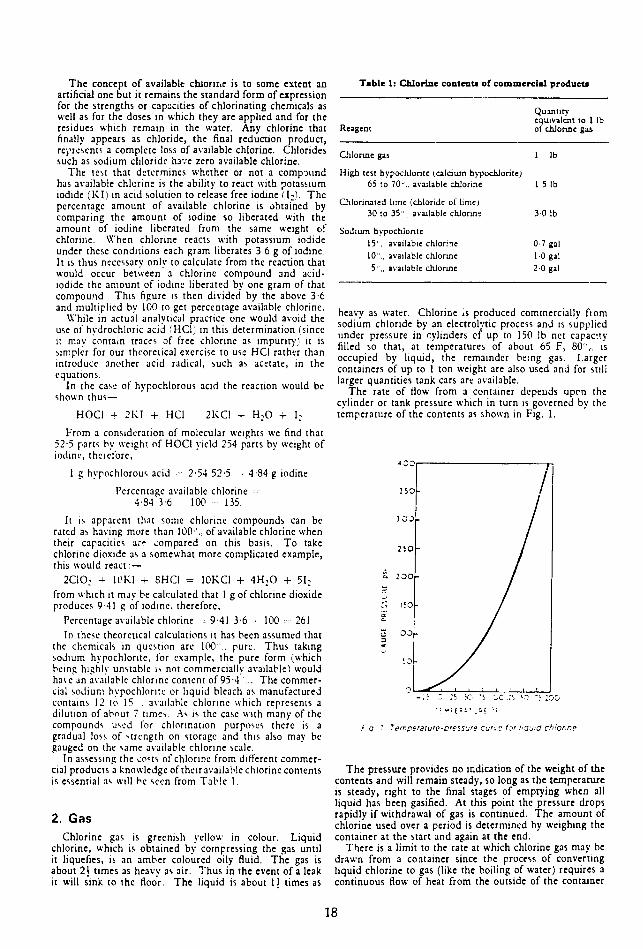
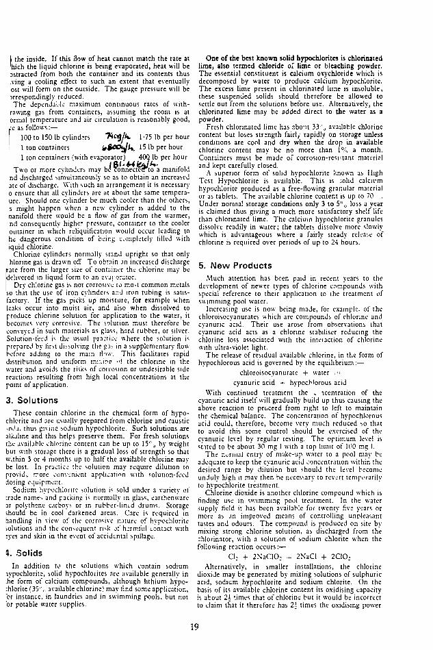
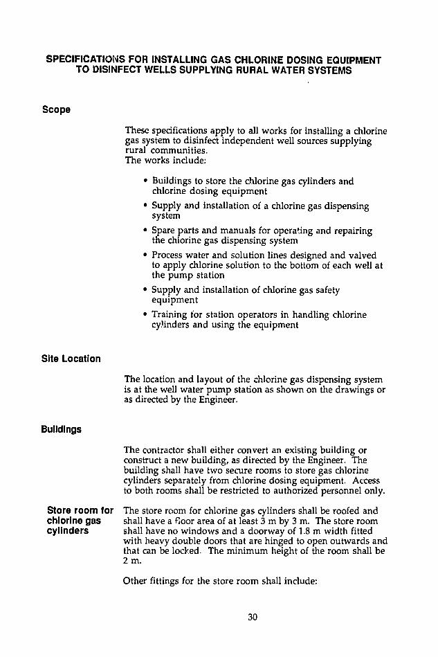

Item No Description Qty Unit Rate LE
Amount LE
13 Supply chemical reagents for 600 residual chlorine tests and 1 liter of ammonia solution to test for chlorine leaks Lump Sum
14 Supply materials and install a 15 mm sampling tap on station outlet pipe 1 No
TRAINING
15 Provide training to the station operators on operating and maintaining the chlorine gas dispensing system Lump Sum
TOTAL AMOUNT LE
38