THE PIPE TEE AS A FLOW METER
62
THE PIPE TEE AS A FLOW METER
Transcript of THE PIPE TEE AS A FLOW METER

THE PIPE TEE AS A FLOW METER

THE PIPE TEE AS A FLOW MITER
SPENCER H. LANDES ., Bachelor ot Science
University ot Illinois
Urbana, Illinois
1946
Sul::aitted to the Faculty ot the Graduate School ot
the Oklahoma Agricultural and Mechanical College
in Partial Fulfillment ot the Requirements
tor the Degree ot
MASTER OF SCIENCE
1951
i

S.PDCBR H. I.AIDES
JaSTER OF SOIDCE
1951
'fheaia Ad'ri.aer
278053
ii
C''.l ~1' ~' · \
•cuLTURA~ & ~t>~i,·:· ,, C·ll,i~I:£ "' • •i-· r,.~ :J•ll•'II
LI BRAR y ..
JUL 26 1951

The author wishes to take this means to express his
appr'eoiation tor the guidance giTen. by- Dr. Leo Garwin•
who suggested this project. The author al ao wishes
to express appreoiation t o the School of Chemioal
Engineering tor the use of the facilities and materials
required to aooomplish the experimental work.
iii

INDEX
ll!!!!
Title Page • • • • • • • • • • • • • • • • • • • • • •
Approval Sheet ••••••••••••••••••••• ii
Acknowled~~ent •
Index to Content
List or Figures.
. . . . . . . . . . . . . . . . . . ~ .. • • • • • • • • • • • . . . • • •
• • • • • • • • • • • . . . . • • • • •
List of Tables • • • • • • • • • • • • • • • • • • • • •
iii
iv
V
vi
S 'UJllll8.r1'. • • • • • • • • • • • • • • • • • • • • • • • • 1
Introduction • • • • • • • • • • • • • • • • • • • • • • 2
Equipment and Procedure. • • • • • • • • • • • • • • • • 4
Results ••••••••• • • • • • • • • • • • • • • • •
Conclusions and Recommendations. • • • • • • • • • • • •
Nomenclature
Appendix
• • • • • • • • • • • • • • • • • • • • • •
-Sample Calculations •••••••••••••••• 37
Fitting Dimensions ••••••••••••••••• 40
Table or Experimental Data ••••••••••• 41,- 52
Bibliography • • ·• • • • • • • • • • • • • • • • • • • • 53
iv

Figure Number
1
2
3
4
5
6
7
8
LIST OF FIGURES
Title
Diagram or Equipnent • • • • • • • • • • • • • • • 5
Standard ·Arrangement of Test Section, Flow in Run ••••••••• • • • • • • • • • • • 6
Variation of Velocit) Head Coefficiept With Reynolds Number. • • • • . • • • • • • . • • • • • • • 9
Ef'fect or Connecting Nipple Diameter on the Velocity Head Coefficient •••••••••• • •
Effect of Connecting Nipple Length on the Velocity Head Coefficient ••••••••
Capacity Charts tor Tees in The Standard Arrangement. • • • • • , • • • • • • • • •
• • • •
• • • •
13
15
28
Variation ot Volumetric Flow Coefficient With Reynolds Number ••••••••••••••••• 29
Effect of Tee Size on Linear Flow Coefficient •• 31
1'

Table Number Title
LIST OF TABLES
I Per Cent V·ariatiori in the Velocity Head Coefficient · from the Control for Each Variable of the System: Flow in Run • • • • • • • • • • • • • • • • • • • • • • • 11
II Variables Affecting the Velocity Head Coefficient: Section III ••••••••••••••••••••••• 12
III Variables Affecting the Velocity Head Coefficient: Section IV. Nipple Diameter ••••••••••••••• 14
IV Variables Affecting the Velocity .Head Coefficient: Section IV. Nipple Length •••••••••••••••• 16
V Variables Affecting the Velocity Head Coefficient: Section IV. Threading into Sections 2 and 5 ••••••• 17
VI Variables Affecting the Velocity Head Coefficient: Section IV. Reaming. • • • • • • • • • • • • • ~ • • • • 18
VII Velocity Head Coefficients tor Detroit Brass Standard Tees in the Control Arrangement ••••••••••••• 19
VIII Velocity Head Coefficients for Crane Standard Tees in the Control Arrangement ••••••••••••••••• 20
IX Velocity Head Coefficients for Stockham Standard Tees in the Control Arrangement •••••••••••••••• 21
I Combinations of Different Brand Tees in the Standard Arrangement • • • • • • • • • • • • • • • • • • • • •
n Average Values of Velocity Head Coefficients for Brands Studied. • • • • • • • • • • • • • • • • • • •
llI Per Cent Variation in Velocity Head Coefficient from the Control for Each Variable ot the System: Flow
•• 23
•• 23
in Brarich • • • • . . • . • . . • . • . . • • • . • . . • 24
XIII Velocity Head Coefficients for Crane and Detroit Brass Standard Tees: Flow into Branch ••••••••••••• 25
nv Per Cent Variation in Velocity Head Coefficient from the Control tor Each Variable or the System: Flow in Branch with Short Nipple ••••••••••••••••• 26
vi

XV Conversion Factors tor Velocity Head Loss to Flow Coefficient ••••••••••••••••••••••• 27
XVI Flow and Velocity Head Coefficients for Standard
XVII
XVIII
Meters. • . • • • . • • . • • • • • • • • • • • • • • •• 30
Fitting Dimensions (By Actual Measurement) • •• • • • • • 40
Table or Experimental Data ••••••••• • • • • ••• 41
vii

StJ:IIUT
fte eltj...,!.,., ot th11 projecrt 'W91"9 thre~old• to cle11p. a tl• Jlf1ter
11h16 ,roul.4 (a) iadioato w1111dn i 5 •· the true rate ot tl• ot 111\dcll, (1>)
not :uo4 oalibrattag. • (o) be inexpe:n.ain and easy to iJurb~l• A .,.._.
1
ot 1taari pipe tee1 a4 001mMting pipe was uaem'bled sw>h that the tlow ot
tlu4• water ill 'th.ii oa••• wa1 direoted brto the nm ad out tu brmoh ot a
tee. A total preHve tap wu in1erted in the plugged. end ot tb.11 tee. A. .
natio pn11ve tap n.a inaeriecl in the branoh opa.iag ot a •••cm4 tee in 11hioh.
the tluicl tloncl ilhrough the nm. '?he two preHure lead.a were ecmaeoted to
oppoai te aides ot a aaaemter. m4 the dittera.tial obtd.J:Le4 ,ru a •UUl"e of
the nlooitJ' pre111ure• tur'oulaoe and tricticm losses in the ayat-. These
1011•• were a:preHecl in tenu ot the naber ot TelooitJ' hew of tlld.4 tlffing.
8\1tt1eia.t cla'H. 'W9re aeoured wit& sneral n.riaticms ot Mter u1abl7
to F8PIN oorrelatiou 'llbioh are aatiataotory in prediot1Jlc eoett1o1•t• tor
tee ..ter•• Oamwml.7 Jmon. brad.a ot tee• were used and were tcnmd to be oon•
a11tent 1n atnetv&l cliJNN1icma ad Motion oharaoteriatio•• lcndn•l aisea
ot tee, tr• 1/4 to 11/2 1nous were 1nn&tigatecl.
With the u.ta preaented• it 11 poaa1ble to eonatruot ad ue a ,moali
brated. . tee :uter with a a:peoted aoouraoy ot ± 5 %. The ater enageMRt
11 tl~l»l•• ad the meter oan be inatalled in looaticma. ,mere 1pao• 1• at a
ldn1'PDllle .. Tu uter i1 ot a!mple ooua'bruot1.on• it 'beooaa a pan ot the piping
ayat-. 1.t iavocluoea :a.o •jor o'batruoticm to tlow• and it appear• to be ap
plioa'ble to all tne• ot tl'Cd.cl.1. ·

2
mRODUCTIOB
The tundu,,mtal basis tor several important devices tor measuring fluid
flow rates is the prinoiple et a dif'f'erentia.l head loss due to restriotion of
the normal flow path. The orifice and veuturi are olassio examples. A seoond
type of tlow meter is the impact meter in whioh the velocity- pressure oi' the
moving fluid is an indication of the magnitude ot now. The pitot tube is of
this type. Two standard pipe tees can be assembled into a meter whioh am.bodies
the prinoiple ot operation ot the impact type meter. The tee meter is ,miq-ue
in that opening• tor pressure tap leads are already present. the lead being
attached to 1:he "tmused opening ot the tee. When the lead is taoing the direc
tion of' f'law• the pressure against it is the total pressure of the fluid. When
the lead is attaohed to the branoh oi' a tee in 11hioh the flaw passes through
the run, the eta.tic pressure is obtained. Now it these two pressure leads are
attaoh.ed to opposite sides ot a manometer, the dif'i'erential observed is the dif'
f'erence of the two pressures, the impact pressure • .All additional head loss can
be measured ,men the static tee is located on the downstream side of' the impa.ot
tee, due to turbulenoe and f'riotion losses in the tee and connecting pipe. An
estimate ot the differential that would be expected i8 aa i'ollovrss-
Impact pressure ot fluid Turbulence loss in branched flow 4
1.0 velMity head bl velocity heads 2.3 velocity heads
The small additional head loss due to friction in the oonneot:f.ng pipe is not
inoluded since the magnitude or 'this head will vary with the dimensions of the
system.
Ver,r little information has been published on the use of tees as i'low
meters. In a reoen.t article. Bord? has described an arrangement of 1ft inoh
tees that olosely a.pproaohes the system investigated. The sta.tio tee was locat
ed innediately upstream of the impact tee. and air was the fluid flawing. The

3
results indioated that the tlc,w ooef'.tioient, defined by O in the equation
V • o-J 2g~R., approaohed a oonstant n.lue ot o.·75 with Reynolds nl.Dlbers in the
turbulent tlow range. It was suggested b;y Hord that eaoh meter be calibrated
prior te ue. llowner, in.suttioient data were gi Ten to eh.ow that this was
aotual.17 neo•••UT•
Ccmsiderable intor.aticm. is an.ilable on the f'riotion etf'eota in piping ., ., ayatema 'Whioh oontain tees. Hoopea ~t a1? tomd that the extent ot reaming
ot the nipples •ozm.•O'tin.g the tees had a prono1moed. etfeot on the friotia
leaa••• The clistanoe the nipple was screwed into the tee was not oritioal.
A ourve of velooit;y head loss vera~ Reynolds number indicated th.at the loss
approuhed a ocm.atanb n.lue of' 1.0 at Reynold.a numbers above 10.000. FreemlZl.1
d11oovered that tMa plugged with a short nipple and oap had approxillately
one-ib.alt the tricstion loss incurred when plugged with a oonTmJ.ti<m.al. plug. an
obaern.ticm that tu.med out to be or interest in this inTestigation.
Elbow meteraS and valve meters' have been described in the literature.
The aoouraoy ot the elbow meter limited its applicability, whereas the Talve
meter, upon oalibratioa, was found to be an accurate means of' meal!uring tlcnr
rates.
The aphe11ia ot thia investigation is on simplicity' ot oonatru.otion and
high aeourac;y 'ldth.m calibration. The elements to be studied are the var
iables introduoed. by the ue of' dit'f'erent size fittings• dit'ferent brands•
dii'ferent arrmgem.a.ts., and the corrections to be applied to the flow ooef
tioient when the ayatem. T&riea in Ph,ysioal form from m adopted standard
' arru.geJ11tD.t• .•o selected because ot its reproduoibility' and relative insen-.
aitiTity' to :minor nriations.
1

EQUIPMENT AND PROCEDURE
The ayst• ot pipes and fittings was so arranged that the flow ot water
from a constant head source was directed into the run and out the branch or
4
one tee and through the run ot a second tee located further downstream. The
discharge was collected in a weigh tank. Figure l illustrates the arrangement • .
To facilitate the inveatigation of the meter characteristics, the com
ponent part.a ot the test aection, P'igul'e 2, were numbered conaecut1••1J' and
studied indi'rldual.l.7 in a standard horizontal arZ"angement. The initial
experiments were conducted with 1 inch nominal pipe and fittings. The up
stream calming section was 44 diameters in length and contained straightening
vanes consisting of a bundle of 1/4 inch copper tubes 18 inches long~ Fluid
entered the run ot the impact tee, and left through the branch opening. The
impact pressure lead o.t 1/4 inch pipe was connected to the meter by means o.t
a street elbow, a reducing bushing, a coupling and a short nipple. The nipple
connecting the two tees was cut to 7 3/4 inches in length tor compactness.
The static pressure lead of 1/4 inch pipe was connected directly to the static
tee by means or a 1 inch to 1/4 inch reducing bushing plugging the branch open
ing. The nipple on the exit side ot the static tee was a 5 inch stock length.
The several pieces ot auxiliary equipment are shown in Figure 1. A con
~tant head tank was fabricated trom a 55 gallon drum by attaching a 1 inch
overflow pipe 5 inches trom the tank top. The tank was supported 15 feet above
the noor and titted with a 2 inch pipe downspout. This source pipe was
connected to a Tuthill Model 4M gear pump. The discharge trom the pump passed
through an orifice plate loc·ated at the entrance to the calming section. The
weigh tank was .fashioned from another 55 gallon drum by cutting out the top
and titting the drum with a drain connection. The tank rested on the platform
ot a 500 pound capacity FaiZ"banks scale. The Merriam 30 inch "clean out"

Herriaa .:::---30" manometer• ~
=
Figure l
DIAGRAM OF ~IPMENT
j ~ i-i ~
II .1
ri ~
·1
iLJii_i' 11 ' ;
i Ii ~ ~~~ --~c--=----~-ur----
t ,.
~ Tee meter, o. 50" oriti ce see Figure 2
•
: I - - - M·.- - - I f-
l I I I ,_,
Tuthill gear pump

I '
to manpmeter
I
t
Figure 2
STANDARD ARRANGEMENT OF TKST SJcXTIOR
FLOW IN RUN
Legend:
Section 1: Calming aection--44 pipe dia.Jietera n 2: Impact tee " J: Impact tap, consisting or 5" nipple,
It 4: coupling, reducing bushing and street Connecting nipple--7 3/4"
n 5: Static tee " 6: Static tap--reducing bushing n 7: Downstream nipple--5"
elbow /

7
style JUJ10D!9ters were titted with air bleeder valves and :momted on a baokboard.
The :meter manometer contained oarbou tetrachloride• with a speoitic gravity-,
of +• 584 at 70• F • The manometer leads were tilled llith the fluid flaring• i.e ••
water.
To aooomplish a run, the tank was filled and the supply- adjusted to allow
a.u overflow throughout the duration or the rmi. The pump by-pass va.l Te was
opmiecl• the pump started u.d tl• rate through the meter adjusted· .. )y manual
ooutrol of' the diaoharge and by"-pass Talns. '!he :manometer readings~were
recorded during the period in which a weight of water was being collected.
Damping of manometer fluctuations was done by throttling the nl:ve on the im.
pact lead until large surges were eliminated. Timing 'W'ILS done with a stop.
wa.toh.
Pertinent data recorded included manometer readings, run n'Ulllber, time of
run. tare and gross weights• temperature of water, and exact dimensions of the
flow meter equipment under test.

RESULTS
As previously mentioned, the theol'Y' of the tee meter is based on the
measurement or the combined impact head and friction head loss tor a .fluid
flowing through the meter. The differential, in velocity heads, between the
measuring points can be calculated by dividing the head loss, .6H, in feet,
by the value of' one velocity head, v2/2g. This number of velocity heads has
been denoted by the letter K throughout this report. With this velocity head
coefficient, K, readily calculable from manometer and weight readings, the
variables can be analyzed in terms of the percentage variation or the coeffi
cient obtained from that tor the control or standard arrangement such as
8
shown in Figure 2. The velocity head coefficients were compared at a Reynolds
number of 40,000. It is in this range or flow rates t~at the K's approach a
constant value. Examples are given in Figure 3.
In addition to the velocity head coefficients, orifice meter coefficients,
defined as C in the equation V • c..J'2g ~' were determined. Upon solving this
equation for the head loss., AH• ( l/C2)(v2 /2g}, it is seen that the relation
between Kand C is K • l/C2• Thus, the per cent varia,tion in K will be twice
the per cent variation in C. A complete sample calculation is shown in the
appendix. Other convenient coefficients are defined to enable use of other
manometer fluids, different flowing .fluids, and other pipe si~es. They are:
Q • C•~ and Q • 01 '~• Using ~he latter coefficient·, plots of the
volumetric .flow rate versus the manometer reading were prepared for the various
sizes of standard meters.
It is worthy' of mention here that the inside pipe diameters as given in
tables in Perry's handbook8 were used to calculate the coefficients, regardless
of how much the handbook and actual values differed. These diameters ordinari
ly agreed to 21,.

0 . a
L--
0
N 0
N
' : i :-1' : • i : ! ' ' i .
, ·- I
: -\ ; CI : : ~:- ' . ' ' 1 T .. ; ·
i ' < ' 1'· ; , I [ ' f·-1· ,· J . : ·i i ; ' · -, · · _____ : '. T',, . : , : : : . : I . ; ---1 ;I r -., ·i .. -,-·-------~ I - ' ' r-r-r i
i ; ·r ,--- ;--'-;I,,_,,---!.-_],+-•. •- t--- ; i '. : . ! -~----,--
• ~
! l ; l -.· - -;
' ' • ! ·-· l • I : . -I I ' r 1 - r : 1'·: ' i : I ; :
: ' ' I ' I . ' ' ' I ' ' I
L I ; I I ' i ; . , ' -- • l t I ,
r· I ! I __ :_ I ' l I i. I I t . r r t '
i ~ :J... ! ; ! (
. ~
§
§ ... ~
§
10
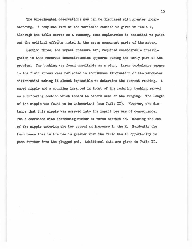
The uperimental ..obeeNat\ons now c.an-be ... .diacuss.ed with greater under
standing. A complete list or the variables studied is given in Table I.
Although the table -serves as a BlJIIIDU7, some explanation is essential to point
out the critical etre;ts noted in the seven component parts or the meter.
Section three, the impact pressure tap, required considerable investi
gation in that numerous inconsistencies appeared during the early part ot the
problem. The bushing was tound unsuitable as a plug. Large turbulence surges
in the tluid stream were reflected in continuous fluctuation ot the manometer
ditterential making it al.most impossible to determine the correct reading. A
short nipple and a coupling inserted in tront ot the reducing bushing served
as a buttering section which tended to absorb some or the surging. The length
or the nipple was round to be unimportant (see Table II). However, the dis
tance that this nipple was screwed into the impact tee was or consequence.
The X decreased with increasing number or tums screwed in. Reaming the end
of the nipple entering the tee caused an increase in the K. Evidently the
turbulence loss in the tee is greater when the tluid has an opportunit;r to
pass further into the plugged end. Additional data are given in Table II.

\
Section
1
II
II
II
II
II
"
2
3
ti
II
II
4 "
" II
II
II
II
II
TABLE I
PER~ VARIATION IN VELOCITY~ COEF?ICIENT FROM ,!!:lli CONTROL
Variable
(l)a Cal.CTing section of 6 pipe diameters, no straightening vanes
11 Calming section or 10 or more diameters, no vanes
(2) Straightening vanes ending 5 diameters before impact tee
11 Straightening vanes ending 14 diameters before impact tee
(3) Inclined a little from horizontal (4) End of pipe reamed to 1.14 inches (5) Turned in 3, 5, .or 6 threads in tee
(6) Brands of tees--see Tables VII-XI
(7)
(8)
II
(9)
Length of nipple and couplingsee Table II Threaded into section 2, per turn < 5, see Table II
Threaded into section 2, per turn >5, see Table II End of niprle in section 2 reamed to 1.14 inches
(10) Diameter or nipple--see Table III (11) Length of connecting nipple-:-see
Table IV (12)
(13)
(14)
II
II
"
Nipple end into section 2 reamed to 1.14 inches---see Table VI Nipple end into section 5 reamed to 1.14 inches~see Table VI Threading nipple into section 2, per turn < 5--see Table V Threading nipple into section 2, per turn ::>5--see Table V Threading nipple into section 5, per turn <5--see Table V Threading nipple into section 5, per turn >5--see Table V
FOR EACH VARIABLE OF THE SYSTEM: -- ------Per cent variation in K
from control Nominal size, inches _!__ ill ill
12.0
o.o
7.5
o.o 0.0
-1.7 o.o
o.o
5.0
-5.3
9.6
-2.4
-14.3
o.o
7.8
-5.1
1.2
o.o
0.0
-8.1
o.o
5.0
-7.5
4.2
o.o
-1.0
Section
5
6 II
II
7
II
II
a Numbers in parentheses correspond to those ~iven in Table XVIII, Table of Experimental Data
FLOW IN RUN ----
Variable
(15) Brands of tee~see Tables VII-XI
(16) Bushing on static tee tap II Short nipple before bushing on
static tap (17) , Threading bushing 3 turns into
static tap tee
(18) Length of nipple from section 5 to elbow, from 1 3/4 to 7 inches
(19) Threading niople into section 5, from 3 to 6 turns
(20) Reaming end into section 5 to 1.14 inches
Miscellaneous variables
(21) Section 4 vertical upward, section 5 in line with section 3 tap
II Section 4 vertical upward, section 5 facing 90° from section 3 tap
II Section 4 vertical downward, sect-ion 5 tap in line with section 3
Per cent variation in K from control
Nominal size, inches _!__ ill ill
control
-2.5 o.o
loJ
o.o
0.0
-3.0
o.o
o.o
-0.6
+ ny Top View (Exploded) Of Control Meter
u C)
~
01 Crane tees All nipples screwed up five turns in tees K1 s compared at Nae of 40,000 Actual diameters of connecting nipples
~ were 1.040, 0.818 and 0.622
612i~ side view of static tap
[Il1u 4 ,11~CL
6~7-~~~ 6 k -s' ti,,
j~
+ .L
D l~to
manometer
11
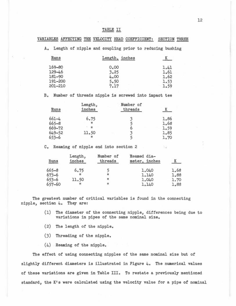
TABLE II
VARIABLES AFFECTING THE VELOCITY HEAD COEFFICIENT: SECTION THREE
A. Length of nipple and coupling prior to reducing bushing
!!!!! Length, inches K -169-80 o.oo 1.41 129-46 3.25 1.61 181-90 4.00 1.62 191-200 5.50 1.53 201-210 7.17 1.59
B. Number of threads nipple is screwed into impact tee
Length, Number of Runs inches threads K
661-4 6.75 .3 1.86 665-8 II 5 1.68 669-72 " 6 1.59 649-52 11.50 .3 1.85 65.3-6 " 5 1.70
c. Reaming of nipple end into section 2
Length, Humber of lleamed dia-~ inches threads meter. inches K
665-8 6.75 5 1.040 1.68 67.3-6 " " 1.140 1.88 65.3-6 11.50 " 1.040 1.70 657-60 " II 1.140 1.88
The greatest number of critical variables is found in the connecting nipple, section 4. They are:
12
(1) The diameter of the connecting nipple, differences being due to variations in pipes of the same nominal size.
(2) The length or the nipple.
(.3) Threading of the nipple.
(4) Reaming of the nipple.
The effect or using connecting nipples of the same nominal size but or
slightly different diameters is illustrated in Figure 4. The numerical values
or these variations are given in Table III. To restate a previously mentioned
standard, the K's were calculated using the velocity value for a pipe ot nominal

. 13 ' 1-:--~---T-i ~-r-·-11-i ---y-r- ' ' ! -! ,---:--r-·,-T-r--·r-n ----- --··1 ·· : -- 1 ·· 1 ·-!--- ·t - -1.f ! ,_ 1 t ' J + -+ I : + : · I : j · : · · · i J ---:--r--· ;---j- ;:·-t- :_·-- -:----------·:--1·--;--,--; ---r r--~-~-r-- : -i,··-··· ···i--'-·-r- :---1 ---! --· l1· :· j ; '11 -: 1· -; ·+ ·:· ·II · j--· 11 -: --- ~-- : -- ,- .· .. .... : i . , . ·j : -·-
: I ' ' ' ' . i i : ' I I I ' '
t i ! ~ ; r i i -~ . : - ; 1 . 1 · : - : r -~- 1 : t : j ' ' I I •
: : I I I I : ' I ' ; I j I I I I -~- - - : -"-1--'-('-l "·+ '~!!If" ~ f~-t-++J-~---1-----~--t---:-----r-·- ---1 [ + i- -!-~=t!~_;j;:~:~~ 1---~~- -~- : ~- ~· ~
: •·: 1, 1-- , i,HF:cor'1: 1: · ·: · 1. 1 -1
-r-~ - ;· ---- ----t--·.-r- -r--~--t--i-+·-r+-; -r--,-----:-~-f --- -- : ··· --·--1 -1 j : . , t-zi . i - : j . ' .. 1,-- -. it.. .. ! -- f . ; -- . . ; . . ! 1, j I ' • I ' I • I ' ' ~----: ·--l--: ___ ! ____ . . .. i---: -- - ; 1-·t·-t1A ch: ___ : ___ rl __ : ___ j·-------1---· :·---1---- ~
... l : I ; . . I ; I i· : . .· . . . . ,- ' I.. ; l . l . ! } ____ t! __ _ _ -- i· ---- _j _____ -r--- '. ... .... f--- -~--1----_ --· ' ---- _____
1 __________ _i _ _ .:_ _____ l---- _ - l--------1·----
• ' ] ' ' I I l t 1 • ' I . ' ;
~ ! I I I ! I : I ' I ! ' I ' - I · l : 1 : : 1 ·: I··; ·, -:---- .. l " · 1 1 . ! i - !
---t-·.-----f--·-- --j----·---t---~--t------f~·-1-· i I ~---i--~-~--~-·-·: -i- ----t- ----i I . . ! ... ! . . ! ..• I : i ' -1 ; l : + •.. 1-; I . . i ! I
- ·1 __ T __ _ --·t --- . --r----f---.---~---1- !-+-:~-----:---r-·- ___ I _____ _ -1--- --: -- +--- 1 : . I ' . I . . : . I :· ·1 . f . . : - , : ! . '.. 1· : ·· J . I· i . -f I r · --r----;-- -: -- -- -+----- --t-- --- -- 1J ____ :_ ---t--+-----r--t-t+-t·--, i--- :---·t -· (--~---t
1
1 ---- ---..,1:
r K 1 . ! I . ! . ' '. . ·!· . 1 : .. , I . : ·1 . . 1 ! : . t.9- ' -_'._ ______ -.i. + -___ J __ -- -J ____ ~ ___ l_ __ ·-·· -1-----~'.--+-' --_j_ __ .... ... .L. --·- __ )___ __ : ____ 11_ -- .. --~ : I I : ' I ' i . I ! . I : i ' ! ' I
t - : i i - : 1 - · - : 11 ; --J· f ; ---1 -- 1--·+1 :· r : : l · , 1
· ·-:--··: --------r----~-- -·t·---:--- ~r---~ :.-. ·:· ! _---.:~~, i ____ , .-:;-j---~----~r---- -~t,. -- ·--·-r~- ---11
I ' ' I I • I ' I : • . : JI . ' i : I I l
. .!I - : -- · . - ! ~ A~~!:::::r=-+:-_-:~-i--f--i---···: ---1 -----r -·--- --,--- -- ·-t ----1 · I nr i , ;-,;.... · ' · · I ' I · L i t , , i I ! • '. . , I ; , :
.Q ··1- · --~® I I r · ··t - ._:_-;;.~--- 8 1 --- -~-, -1
. ---·;:l 2- incl, ,-- -- · - r·--··-- 1--- --· i i I I ' I ' \!, ' I ; . ' ! I,, : i : !
.~ _' ___ 1 !--.- 1. !f-4 ~~t-:-+-: -+~f L~: ___ ! -l--,- -i-. - ! 1- ···j · i.i :·-! · i · t 1 ··: :-- 1-··t':1·e ! + l
- -; ----f--·-·:--·+--- :----:---------+-- ·--·-,--L---1- ··, --+-I I . . 1--+------ - i~i- -~----l ' ------~ : i ! ! ' · : ! I r J ) 1 \ J I j ' . ! : • ' : I . . I . : . -. : ... . . 1-- 1' t ; ;
' I i I j I I I • i I I .) ----l
0.97' ' o.~s I 0.99 . l~O ' I 1.01 : lo02 1.63 I ! : f · I l . Actual dJ.!metet ~ · t' : · j : i ! , ·,·
L _ .. --- ·-·--;--·-t--·· ·----,-1 --:·- -1------·- r-· . Hand!, bo~k ~, 18f-*'jfr-il-- -;·1-- ---t -- --·-r·-·--·--t----~-·-·1 ' I L I ' I t ' I l .. ,· I I . : . ' . l' .. , ·: . i . . . ... ·, . . ' . ' I . : I • .. . :
--· :----- /-···-- -+-•: ---:--- ---~1----:----1'··- -: ... +- :--r- :~~-+~---1----- t----:--·~ __ ' --i-· .. : ·- I
' I . I . . II • ; J I : ' I i I ! I I .... , i ·; i . ' --, - - • -- 1 ' I - ! . , ! 1 - : .• • : .. , . - • - 1 •
I _j__l_ l ' 1 l ' ' .__~__..,_.,__
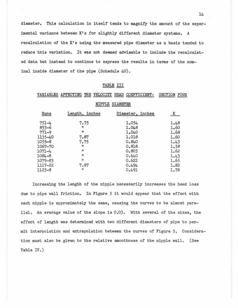
14
diameter. This calculation in itself' tends to magnify- the amount of' the exper
imental variance between K1 s tor slightly' dif'~rent diameter systems. A
recalculation of' the K's using the •easured pipe diameter as a basis tended to
reduce this variation. It was not deemed advisable to include the recalculat
ed data but instead to continue to express the results in terms of' the nom
inal inside diameter of' the pipe (Schedule 40).
TABLI III
VARIABLES AFFECTING THE VELOCiff ~ cpEFFICIENT: SECTIOH lQ!m
HIPPIE DIAME1'lf
!!!!!! Len~h1 inches Diam9ter1 inches ..L. I
751-4 7.75 i.054 1.48 85.3-6 " ;l..048 1.60 771-9 " 1.040 1.68
11.35-40 7.87 1.018 1.60 1055-8 7.75 0.840 1.4.3 1067-70 n o.a1a 1.58 1071-4 " o.so.3 1.62 1084-8 n 0.640 1.43 1079-8.3 n 0.622 1.65 1117-22 7.87 0.49.4 1.82 112.3-8 n 0.491 1.78
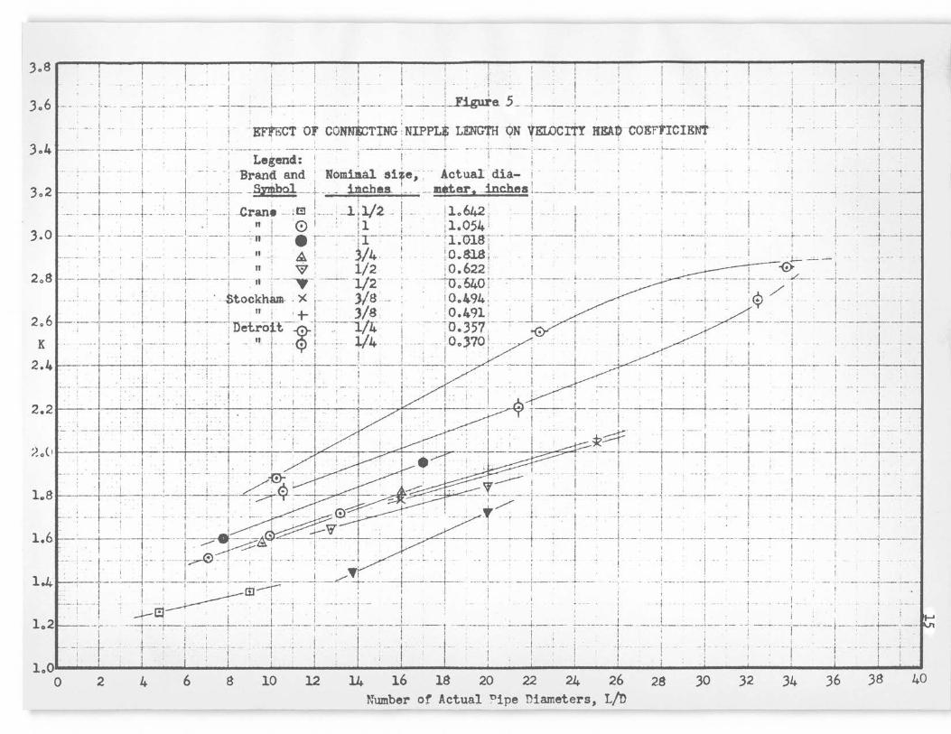
Increasing the length of the nipple necessarily increases the head loss
due to pipe wall friction. In Figure 5 it would appear that the effect with
each nipple is approximately the same, causing the curves to be al.most para
llel. An average value of the slope is 0.0.3. · With several of the sizes, the
effect of length was determined with two different diameters of' pipe to per
mit interpolation and extrapolation between the curves of Figure 5. Considera
tion must also be given to the relative smoothness of the nipple wall. (See
Table IV.)
! ! 1' · ' I l .
. I -- - • •. I I . . . t i . . J ·- . : . I . ! . l , , , ' : : ' . I I ! · ' I .
306 J-·-- ·- --- .-- -r--~---1--·.- ~----. --~ --~--- +--------1----- - -: --: --1-~a 5 _ -+----- --:--·-:·- --- .. --f----------·r ·--- -, -- -- - -+- -- ----· -. ·------' ! .. : j 'EF"tbCT or CO~ING ;N!PPL* LENG1'H "QN VELOCitt KEA~ COErtICIEN't ! - .... '
3o4 J--- ---·- :----: --·----i- --.-- --[------·-:-- --~--- -'. ·-- ---- ·- :.---·--· __ ; ·-· -···--+-· ------ -:------·-----:------- . ---:----- --· \------ ---. .,~--------·- ···' '. i ! . 1 Legend: : : ! , 1
1 1 1
f---- 1· ' - -- :·Brand and : Nomill.al. siie; · Actual dia.- i ! · ! ·! ' ····· ··· · .. ., . l. I · ~a1 · I . jh l ' Ii 3 0 2 ~---+---+-·-- -t----;---+-- --+· -- illl.chU. - - - --$el"aDC ftS , ______ I____ - , - • ~- ------, --- . ..... . __ ---- -i
308 ;
t·
1 · . • · I ; . 1 1 1· , 1 l • ; , , . I I i I . . ,.. ' . "" ' l. ' 1/..., 11 LJ ,.. ' I ' ' I ' ..... '. -· -t· ------,---·- t·· ..... · ......... ., ····· ·'! -vr.an• ---! ~ i··· ··'-- I 4,- -- :1 ... · -- , o~ • ··· , r• ! · ]- .. .. ..... .
I , , . 1 . , , , , r , , 1 1· -
' I ' · ' I " I 0 I : !l . ; 11.054 : ! ! I i J.O J--- -- :- ------/----.--· J-·- ----:--- -~-» i--- . ; -- ---;r- ---~--- ·· - -·\ :01sr·- --·:--: --- .. ----!- - ----/-------;··- ---- -- j·· .. - --+- __ ., +-- _--·-1··-+-
: - . ' ······· : . . .. .. . ! II ~ )/4 . ; :Q.81.8 ; i i I . ; .. _, .. L .. . : I · 1 - . i/ · : , · : - -- 1 : . I l ' n w , . 2 , ! 0 o 622 : ! , : , ! ~ i i
208 l------!----.--t-· ---1----1---" :-~ --: ·---- ·112·· . ··:0:"64o r -:-----r --~ -~- --- ----,----- - + -------r-·--:;·f-- -i-- - --;-·----' I ., I / ' ' . ' ' ' / ' ' I · f -·-- ·!- -- · ·1 - . '"4>tockham- -X ; .. - .) 8 - : i __ o.494 : . . --i- ,~ ; I . , . 1 I . I / I I I I , y' I I I 2.6t·--1-----+--~---t--· -~~--i·:-~T ___ + _t---~--~--t -... --~ -- -- ~ 00 ~-:~:- ---.. _J_ -- · --~--------L_ -------J---~--
. I . I ; uew-Ot-t. f ' . -L/.t+ ; ; ·~"' 1 • ! ! ; '
K ---·~11 --- - - -- ' - --- - I ... ~ - ,, 1'- . • J - :. 114 - .1 ---- -- 100}?0 1 . ;. l. . ! .: . .. 1 , ' ' ' • +f· \ I I 1· • ' l . I ' I l ; I • I ! I : ' ; • : l I I . ! :- I . l I I 2. 4 --- ·--+---,-- ___ J ___ ___ r-: --------------t-··---·· · ··-r--·-----l-----'----·--r---- - - -+-
: I ' i I . I . . . . ' i .. ' ; I I . ' ' l ' ' I ., ; . ' I ' • . I ' I ' I I I -- :--~ ---- (1:t·:·: :· ~j-- ;·· ··r ·:·;- -T- :--- / .. - . 1- ... : . -'. - 1-- : , : --- i . 1-- · i , ·j··· 2.2 ~-- . - - - -~---r-- I I • 1-------·---1-------i-,- 1 1 : l : . . ;., I . . :. . : l . . : '1 I ! . I I • l
•: • , : · r : · I , j ; I ,
-·- --,-~- . --;---- 1-·-- '--~!--- ;·····tl ___ ; ___ l 1i· : . . !···. I ..----±:: i ____ ! .. --+·-- -·; · i· · ·-· l .. '.. ! l · +· f· · 1 · 1 • i I · · -i · i -+,~-- I I , l , i . . . . : i-· . I ! . : . I ; . . : ' )!(~ I • i I ' !
~o( I~ I - I-:--· : .. :- -:---t:-,. - ·- I -. z·--,- . ----1 i - ----·-t-, · ---,-~:·----i----, -i ---..; .. _t-- ' -1---; · - I --~ -1---'.. · : .; .. ~ --- .. ----- !-- .. - ; 1 .. : ' : I ___ · ! ···-•- \· - f .... :. -!-- I ! -·,: ___ _____ J I . ' l : I • ! /1':J: ' ' ~ . l ' ,----- I ' I ! ' : ; l . l .
l.SI . : . . l-~~1-:-t-~-r-c_714-~co ~ '. __ -·r:-r~-r~t- -J---!- -r----r---1--:tl_ I ·+ I I ' I I ' I ' I . ' I ' I , I I · . : • i ; . · : l '
1.61-:-----+-- ---- --+--_::..-------~ 4----~-~---+--: -~------~-----·-·; ________ ; _____ l ______ _: ______ ..J__ --·---~---:--
! , - ~,II . ,, 1 ,I , :• · j 1 !
1.4
' i t . I f I t ' l ' J
-- . - - 1 - . -- -1-- . . . t. "-' - . . L. .. . : .. 1.. - ·- .. - 1 1 - - :. . . . 1 ! . .. -~ 1 . 1 . 1 1 . • , ' ! ~ ' 1 I 1 • ' i i J ; : ··: _.J I. _., I ' .i I I ' . ' ' i :--+----: . i--~ !-- ~----!----~-4---·-· :---/ +-· ·--+--· --!------- -: --.. .. ---!-------+ -- . : . _: ___ _____ _; ___ _
I ! ·· ~L;.1 1'' I [ i , -·-- }-·-- --~ ! - --~~ ;- - ·- ~- - - - 1 --~ --·---- - -- t---- ··- i ' -: ! '. . • . • · .j · ·t --· ··
I
L . I .J--~ . ' I . I . I : . ' ' : i
lo2h - ~ -y · ; j I J . i : : , ; · l ! - -- 1 - · ---+- . ; t- ___ L ___ --: ----·- · _
----- i- -- +---- + -~ ,-- .. 1, --, -l - I 1'.. --j- _1 __ : -l------ l - - 1--- · •• • 1,
i . '
-- f--- ·-t-· ---i ... i - -. . ~-- ~-I : ! ; l ' ' I I I ! I i i ! I f I ' I I ( j I I
loO I I I f ! i 1 · : • : •
0 2 4 6 8 10 12 14 26 Number of Actual nipe Diameters, L/D
16 18 24 20 22 28 30 32 34 36 38 40
16 ..
'UBIE IV -. .... . . VARIABLF.S AFFECTING !Im VELOCITY™ COEFFICIENT~ S:ECTION IQ!!!
HIPPLE LENGTH .
!!!!!! Length. inches Diameter, inches !lE!? ~
747-50 7.75 1.054 Black l.50 735-8 10.50 " " 1.61 739-42 u..oo " " 1.72
1135-40 7.87 1.018 Galv. l.60 1129-34 u..oo " " 1.89 1067-70 7.87 o.a1a " 1.58 1063-6 13.12 o.s1s It 1.82 1079-83 8.00 0.622 II 1.64 1089-96 13.12 0.622 It 1.a1 1084-8 8.00 0.640 Black 1.40 1097-1104 13.12 0.640 " 1.70 lll7-22 7.87 0.-494 It 1.82 1105-10 12.12 0.494 II 2.01 1217-25 8.00 0.370 " 2.15 1233•39 12.00 0.370 " 2.84 1226-32 8.00 0.357 Galv. 2.45 1240-6 12.00 0 • .357 " 2.65
Threading is not as disturbing on the end of the connecting nipple into
th~ impact tee as it is on the end into the static tee. Five or fewer turns
into section 2 or five or more turns into section 5 do not materially affect
the coefficient. However, threading in the opposite direction than that
mentioned above produces significant departures. The standard procedure in
all control rune was to thread all nipples into the tees five turns. (See
Table V .)
.
17
TABU: ! . .
VARIABI.E uncmn !Ill VBLQCITY ~ COEFFICIENT: SBCTIOI fQY!
TBRlW>DG !!lQ. SECTIOIS i. Alm j
IOllinal size, Threads Kuni inches · turned in Section ....L -
677-80 1 3 2 1.64 681-4 n 5 2 1.66 685-8 " 6 2 1.79 689-92 " 3 5 1.49 692-6 n 5 5 1.64 697-9 " 6 5 1.65 876-9 3/4 4 2 1.52 857-63 n 5 2 1.;1 880-3 n 6 2 1.59 881.-7 n 4 5 1.42 888-91 " 6 ; 1.;s
Bxce1aive reaming ot tbe end ot the connecting nipple into the impact tee
11 not serious. lleaming ot the other end ot the nipple into the static tee
can be a cause ot great variations in the I. The standard procedure tor tin-
iahing the end ot the nipple wae to ream the burr to approximately the pipe
inside 4iameter with a regular pipe reamer, then to smooth the remaining ridge
with a round tile and emer.r cloth. The nipples were gauged with an inside
caliper to check tor hidden ridges. From experience it was tound that the e7e
was not a aatiatactor.r judge ot complete burr removal. Although the prepara-
. tion ot the connecting nipple ie a time consuming step, it is probably one ot
the moat important means ot securing accurate results. The magnitude ot the
n.riations observed appear i,n. Ta:~;u, VI. - .
18
TABLE!!
VARIABW AFP'!X:TING m VELOCITY-™ COEFFICIENT: SECTIOI rn WMIID
Reamed dia:- Nipple !!!!! met1r1 inches end ...L. I
514-20 1.040 (pipe id) pnpact 1.68 521-4 1.078 " 1.61 525-8 1.140 " 1.64 541-4 1.040 (pipe id) St.atic 1.61 545-8 1.093 " 1.48 549-52 1.140· " 1.39 553-6 1.182 " 1.38
One ot the points ot interest in the investigation was the tees, the
sillilarity within brands, between brands, and correlations ot coefficient with
structure. In Tables VII-XI, various sizes of the several brands have been
listed along with the data obtained with them. It was usually necess&r7 to
compare both impact and static tees together in a single installation by
switching them since an insutticient nwnber ot tees was available in each size
to test a group ot them against one as a control. Although the nwnber of
samples examined in each size was small, it is believed from the consistency
of the data that additional samples would not materially change the experimen
tal average deviation in the velocity head coefficients. One might point out
an exception to this assumption tor the 1 inch Crane tee No. 3 (Table VIII).
This tee was tested merely to determine whether visual inspection of the tees
would be sufficient to weed out bad samples. The shoulders or this tee were
grooved and sloped, unlike the control tees, which would indicate that it may
have been cast in an imperfect mold. The pronounced deviation from the control
tor this tee veritils that rlsual inspection is important here.

19
TABIE fil VELOCITY HEAD COEFFICIENTS FOR DETROIT BRASS STANDARD TEES - - -
!! COBTBOL AWHGBMIN'.l'a
Size Tee Section ~ inches !zE! !2.t..- locatio!! Viariabl.e ...L
641-4 1 Black 1 2 Cont,rolb) 1.75 <2 5 Confrol 629-32 " It (~
5 Inte. changedc) 1.65 2 Interchanged 1008-11 3/8 " (~
2 Con1,rol) 1.s1. 5 Cont,:rol .
1012-15 It " (~ 5 Interchanged) 1.9~ 2 Interchanged
1016-20 " It (1 2 eon rol) 2.14 2 5 Control
1021-4 1/4 " (1 2 Cont,rol ) 2.15, 3 5 Hew teed
1025-8 " It <i
2 New tee) 2.20 5 Control
1029-32 " II' (1 5 Interchanged) 2.3q 2 2 Interchanged 1 2 . e
1033-6 It " Rev~.rsed ) 2.35 <2 5 Reversed
a Connecting nipple diameters or 1.040, 0.491, and 0.370 inches
b Control position, tee No. 1 in impact position, tee lo. 2 in static position
C Tees interchanged in section location
d A third sample of the same brand and size
e The direction or this tee reversed, location not changed
tABllim
VELOCITI 1W CQIW~-· mt - S'J'~OD DB l!!, cOJl'l'RQL AIRAKGJIIPTa
lcw1na:'!, 111•, Tee Section ·l!D!. inch•• 'l'D!' !2& location Variable X -60S-8 l Galv. ci 2 Controlb) 1.65
2 s Control 6ol-4 " ·" ·1 2 Control ) 1,66 C2 s Reveraedc 609-12 ff, " ·1 2 Rneraed) 1.67 C2 ' Control · 613'-16 " " Ci
2 ·Rneraed) 1.70 s lneraed 617-20 " " ci s Interchangedd). 1,6S
2 2 Interchanged 621-24. " " ci 2 Control) .1.s6
3 ' In tee• 925.-28 3/1+ .. ci 2 C.ontro;L) 1,4S
2 ' Control 92Cr32 " " c1 2 C~trol) 1.-6
3 ' 1.- tee 933-36 " " c~ 2 · In tee) 1.,2
' Control 937-40 " " c~ s Interchanged) 1.52
2 Interchaziged <J41-4S 1/2 " <i 2 Control) 1.66 s Control 946-49 " Ii ci 2 Conttol) 1.67 2 s Revereed. 951-SJ+ " " (~
2 Rnel"sed) 1,63 5 Control
9SS-58 " " ci s Interchanged) 1.11 2 2 Interchanged
a Connecting nipple diameters of 1.oi..o, 0,840 and 0,622 inches
b Control position, tee Ho. l in 1mpa.ct poeition, tee.Ro. 2 in etatic position
C The direction oft.hie tee reversed., location not chang~
d TNe'intercbinged in seotion·locatione ·
e A third sample of the eaae brand and •1••

21
TABIE !! VBLOCiff HliD COBP'FICDITS fC8 STOCIJWI ST.AIDABD TBBS DI CONTROL ARRANGEMBNT8-- - --
Nominal size, Tee Section !BS! inches l'ze! 1!2.t.... iocation Variabl:_! ...L
1258-63 11/2 Galv. ci 2 Controlb) 1.28 2 5 Control
1264-9 " " ci 5 Interchangedc) 1.34 2 2 Interchanged
857-63 3/4 Black ci 2 Control) 1.51 2 5 Control 908-11 n " ci 2 Controld) 1.55
3 5 New tee 912-15 n ti c~ 2 New tee) 1.58
5 Control 917-20 n n ci 5 Interchanged) 1.48 2 2 Interchanged 967 .. 70 1/2 ,. ci 2 Control) 1.79 2 5 Control
. 971-4 " n ci 2 Control ) 1.82 2 5 Reversede
975-8 " ti c1 2 Reversed) 1.82 2 5 Control
979-82 ti II c~ 5 Interchanged) 1.89 2 Interchanged 986-91 3/8 ci 2 Control) 1.82 2 5 Control 992-5 ti " c1 2 Control) 1.86
3 5 New tee 996-9 n II (3 2 New tee) 1.88
2 5 Control 1000-3 It .. ci 5 Interchanged) lo84 2 2 Interchanged
a Connecting nipple diameters ot 1.595, o.840, 0.622, and 0.491 inches
b Control positions., tee No. 1 in impact position, tee No. 2 in static position
C, Tees interchanged in section locations
d A third sample ot the same brand and size
e The direction of this tee reversed., location not changed
22
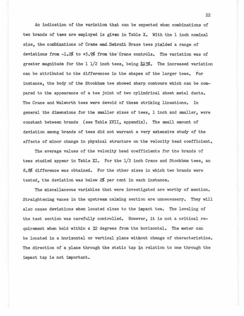
An indicati,on or the variation th4t can be expected when combinations of
two brands or tt?es are employed is giv~ in Table x. With the 1 inch nominal
siie, the combinations or Crane -aad..Jl.etr.ait Brass tees yielded a range of
deviations from -1.2% to +5.9% from the ' Crane controls. The variation was of
greater magnitude for the 11/2 inch tees; being ~3%. The increased variation
can be attributed to the differences in the shapes of the larger tees. For
instance, the body of the Stockham tee showed sharp contours which can be com
pared to the appearance of a tee joint of two cylindrical sheet metal ducts.
The Crane and Walworth tees were devoid or these striking lineatione. In
general the dimensions tor the smaller sizes of tees, l inch and smaller, were
constant between brands (see Table XVII, appendix). The small amount of
deviation among brands or tees did not warrant a very extensive study of the
effects of minor change in physical structure on the velocity head coefficient.
The average values of the velocity head coefficients for the brands of
tees studied appear in Table II. For the 1/2 inch Crane and Stockham tees, an
8.8% difference was obtained. For the other sizes in which two brands were
tested, the deviation was below 2% per cent in each instance.
The miscellaneous variables that were investigated are worthy of mention.
Straightening vanes in the upstream calming section are unnecessary. They will
also cause deviations when located close to the impact tee. The leveling of
the test section was carefully controlled. However, it is not a critical re
quirement when held within a :!:2 degrees from the horizontal. The meter can
be located in a horizontal or vertical plane wit,out change of characteristics.
The direction of a plane through the static tap tn relation to one through the
impact tap is not important.

23
TABLE! '
COMBIIATIOIS OF DIFFERENT BRAND TESS IN THE STANDARD ARRANGEMENTa - ---Size, Tee Section
!!!!! inchee Brand Ho, 105:ation Variable
1264-9 11/2 cstock~Ul 2 2 Controlb) Stockham 1 5 Control
1270-4 " (Stockham 2 2 Cont.r.ol ) Walworth 1 5 New brandc
1275-9 n· (Walworth 1 2 New brand ) Stockham 2 5 Interchangedd
1280-3 " (Crane 1 2 New brand ) Stockham · 2 5 Interchanged
1284-8 " (Stockham 2 2 Control ) Crane 1 5 New brand
779-802 1 (Crane 1 2 Control) Crane 2 5 Control
807-10 " (Crane 1 2 Control ) Detroit 2 5 New brand
811-14 " (Crane 1 2 Control ) Detroit 1 5 New brand
819-22 " (Detroit 1 2 New brand) Crane 2 5 Control
82.3-5 " (Detroit 2 2 New brand) Crane 2 5 Control
a Connecting nipple diameters of 1.595 and 1.040 inches
b Control position
c Other brand of tee
..L 1.34
1.54
1.28
1.18
1.44
1.70
1.75
1.68
1.80
1.78
d Control brand that was interchanged from impact to static location or vice versa
TABLE,!!
AVERAGE VALUES m: VEWCITY ~ COEFFICIENTS FOR BRANDS STUDIED
Nominal size, inches
1/4 3/8 1/2 3/4 1
11/2
Average K for brands of tees Crane Stockham Detroit Brass
2.22 1.86 1.86
1.67 1.83 1.58 1.58 1.67 1.70
1 • .30
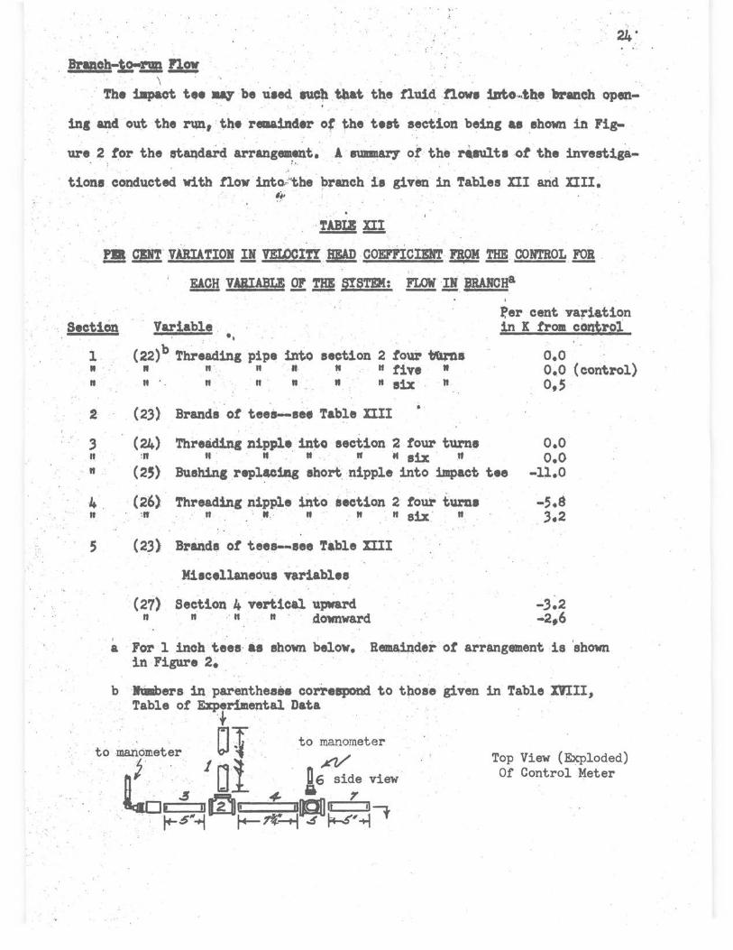
. BrfBoh-.Lo-m& !12! \ ' . ' .· ' ·.
· The impact t,e Jll1' be u1ecl IUCb tllat the tluid tlow1 1.ato ... the branch open-. . ' . . .
' ' '
in& and out the run, ' the remainder of the teet section being ae ehown in Fig-
u,re 2 tor the stazidard arrangement. A 8Ullll&rY' of. the r4ault1 ot the investig~-. ·: . : ,, . ' . ' . ; i
tiona conducted with now into.-,"tbe 1>ranch is given in Tables nI arid XIII. ' ~~
fl! gn· VARIATIOll !! VELOCI'ff ~ COEP'Pl'.CID'l' FROM '1'HE CONTROL IQ! .
EACH VARIABLE .Qt m SYSTEM: FLOW !! BWfCHa
Section Variable . •, 1 (22)b Threading pipe into section 2 toui- 'btu,la " .. · " " n ·· n " " five " n " · . " n · n II tt six n
2 (23) Brandi ot teei--see Table XIII ..
3 (24) Threading nipple into section 2 tour tum, II :n " . " . " . " ,. six . .tt
fer cent variation in K trom contro1
o.o o.o (control) o,s
. n . (2S) Bushing replleing abort .nipple into impact; tee
o.o o.o
-11.0
4 . (26) Threading nipple into section 2 tour turn• n :tr n · " n " " six. "
5 (23) Brand• ot teea-.. see Table mI
Miacellaneoua 'Yariablea
(27) Section 4 vertical upward n n · n . n downward
-3.2 -2,6
. a ··For 1 inch teee·· i.a shown below. Remaipder ot arrangement ·1& 'shown in Figure 2~ . ·
b ·hlllbers in parentheaH correspond to those given in Table XVIII, Table of ~rimental Data
to ma,\Ometer JD{ to ;;;,neter .
nf .·. Di . 16 side view 1rao ~ m .4' ?
' ., ' ~~-~ 2 ~~~9~,~f
Top View (Exploded) Of Control Meter

25
TABLE s.ll
VELOCITY~ COEFFICIE:NTS IQ! CRANE.~ DETROIT BRASS STANDARD TKES ' ' I •
FLOW INTO BRANCH& --. Size, Tee Section
~ inches Brand No, location Variable K
1147-51 1 Crane (1 2 Control) 1.55 2 5 Control
1177-81 ' rt II ci 5 Interchanged) 1.55 2 2 Interchan,ged
1207-11 " Detroit (1 2 Control) 1.37 2 5 Control
1212-16 11 " ci 5 Interchanged) 1.46 2 2 Interchanged
a Arrangement is shown under Table XII. Connecting nipple id = 1.040"
Another interesting observation from branch-to-run flow is that the thread
ing of the nipple of section 3 has little effect on the K. However, the thread
ing of the connecting nipple into the run or the impact tee becomes important.
This behavior is different from that previously obtained with run-to-branch
flow. The magnitude of these variations are less than for the standard arrange
ment, and the thought inlmediately a.rose as to methods of improving the overall
basic arrangement. Since section 4 contains the greatest number of sensitive
variables, the choice would be to eliminate this section. This would require
a new method of holding the tees together, such as using flanged fittings, or
brazing the screwed fittings together. Shortening the length or the connect
ing nipple might diminish the effect ot diameter and length on the velocity
head loss. Several runs were made to determine the feasibility or t~is sugges
tion. A glance at the results in Table XIV indicates that a short connecting
nipple is a satisfactory means or reducing the effects of nipple length and
diameter. Stock nipples of 2, 2 1/2, or 3 inches and of diameter of 1.040
and 1.054 inches give comparable K1 s in this system. The K tor this arrange
ment, 1.17, agrees tavora~ly" with the expected value or 1.23 obtained by

'i . . • 26
extrapolation of the L/D correlation ot Figur~ 5 and· noting that the· K for
branch fiow is approximately la,( lower than the K tor flow into the run (Crane
tees, Tables XI and XIII). The effects due to structural disaimilarit:, ot
the tees may become or greater relative importance with the lower K.
TABLE m PER CENT VARIATION IN VELOCITY HEAD COEFFICIENT FROM THE CONTROL FOR EACH ---- - - -- _ __,_
VARIABLE 1! SYSTEM: nQ! I! BRANCH &m SHORT NIPPLE8
Section Per cent variation in K from control
3 II
"
(28) Threading nipple into section 2 four turns " 11 " " " 2 five " 11 It ti It It 2 six It
o.o o.o (control) 4.5
4 II " II It It 2 four and one-half turns -5.4
11 tt· Threading nipple into section 2 five and one-half turns 5.7
11 " End or nipple into section 2 reamed to 1.088 inches -1.0 It If II If II It II 5 ti II It II -8.5 " " Connecting nipple diameter 1,04.0 inches -2.5 11 " Connecting nipple length 2 1/2 inches -2. 5 " " Connecting nipple length .3 inches 1.7
a. The arrangement is drawn below. Connecting nipple diameter is 1.054 inches, and all assemblies are 5 turns except section 4 end into section 5 is 4 1/2 turns. The K for the control is 1.17.
+ nr . U ~ to manometer
0 lf .n ~ side view of to manometer U L static tap
; ~, .. 'Sit ~ctllO@ .:t II mrED-1 .-1-,1i
J+.6~ k-r.f S t..._7.ft~ -' 2· 1~
i
Top View (Exploded) Of Control Meter
27
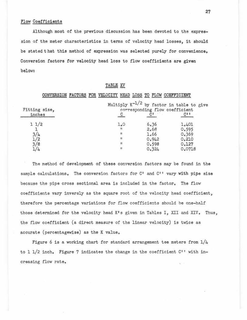
~ Coefficients
Although most ot the previous discussion has been devoted to the expres
sion of the meter characteristics in terms ot velocity head losses, it should
be stated t hat this method of expreseion was selected. purely tor convenience,
Conversion factors tor velocity head loss to flow coefficients are given
below:
TABLE n CONVERSION FACTORS lQ! VELOCITY~~ IQ~ COEFFICIENT
Multiply K-1/2 by factor in table to give Fitting size, co~responding flow coefficient
inches ...Q.. ·c• , , . C"
11/2 1.0 6 • .36 1.401 1 II 2.68 0.595
.3/4 II 1.66 0.369 1/2 II 0.942 0.210 3/8 II 0.598 0,127 1/4 II 0.324 0.011s
The method of development ot these conversion factors may be found in the
sample calculations. The conversion factors for C1 and C'' vary with pipe size
because the pipe cross sectional area is included in the factor. The flow
coefficients vary inversly as the square root of the velocity head coefficient,
therefore the percentage variations for flow coefficients should be one-half
those determined for the velocity head K's given in Tables I, XII and XIV. Thus,
the flow coefficient (a direct measure of the linear velocity) is twice as
accurate (percentagewise) as the K value.
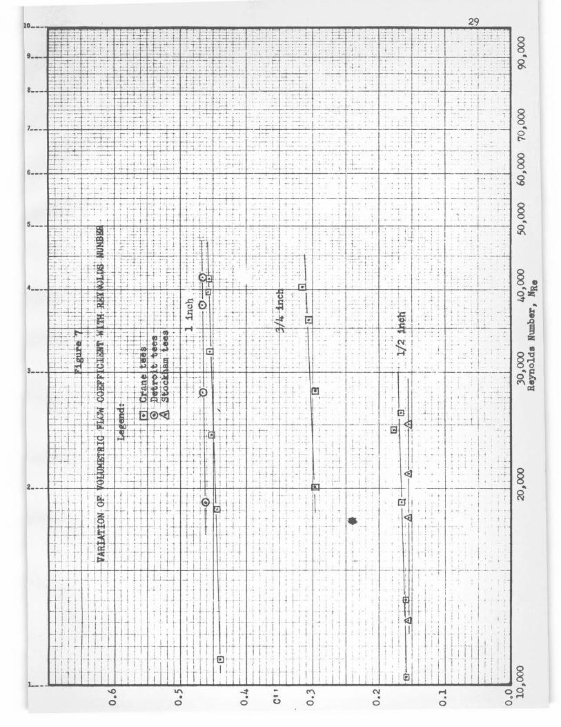
Figure 6 is a working chart for standard arrangement tee meters from 1/4
to 11/2 inch. Figure 7 indicates the change in the coefficient C'' with in
creasing flow rate.

28
~:c.~ ~ -I f H- -~ -1---~-- _J ___ - - --- - P H ! . -- : - -- - 1------ ~ ·· TITr- i L-~ - ++++ i -1 1 -
~cl- - Jjl +r+++ , ! -- , --- i- -·:·t - -- -H-!-J L. -+- ___ J ----~- ~ --~---_ 1[t"!Tn-1-1 I + , : h-r- 1 . 1_~ N
-1--_---iT! 1 ·r···· ! t --1----1-- ------_ ~-1- . T I. i + r· ---1-- _- -- -·-·;_j 8
; ' h_r_j_--+-·-t-i ' --1 -- : tt-· . I ' 1 ~
-- - I • t ~-+-T- ----- · - ---+---i--r---:-- - ' a, ._ __ --- --t---+-+t _L __ i _ _J_ I ! I I l ! I I ; I [ I ! ! , 00
....__.____._~ 1 , 1 j I I j: i - , , : -, ---r- i ! - I ~---+--------ji--+----+--, ----1 .... I ! : ' : I I I . I -- --= -t ff=r~r~- f ~+ ·- · ·c- +_ - - -:c r 1-- ··; --· ----~-~ ---- ~-:
--1-~"1+r1_---: ·---- --- r_ •·· i~ --\ 1 ~ - t·_---~r±-r=~1=----1---~~ --·-11r--~~ ·r- ··t \\~---
111 ~ ------ - ~ -·t-~~1-1 "-t~, -.- · ~ ! ~
"'Jftir-i.-1,-1~\ ·"- i~;t-··~:~(-t-·~rc-_ ~ . . . . ~ 11 . . F .. I ' I ~II . . \ I\\ I . I~. I . \ . ,.i;; N
-~ : i · ~ - 1 . · : I : : ; : ~D • _. K I !8 1 . I ~ : : . -~ .. ~ ~H ---~1--- --+- -5-~ -t~-;-----+-1
___ J _____ L___ --_ _c; - -- --- -------f.u,r\-1- '-·-11--~\- · -i------ -----~-~ -:---pt-
. : ID I h' p i: . . - . . . i\ : : . I\ . ~ - I . \'\j : . . : 1·-: · ; - ; k;l s 4 . . . - - · :_ \\- 1 \ , t\ 1 : : . ._ · ~,~c . --~--· -+' - ~tl : '' I .. -~ ~ ~ I · , . : ; : _: 1 :-+-0
~ I i ! : X:5" \ \I\ i \\ . \ . ... 1m ----r- I - \\ ' . '-7-+- ,..,. , a,
11"' 1 +-'--~--/--: , -\ --· r-) L \ '; ·• f!I \ co
~ : . I i i \ I . \ . \ I .: ~ .\ \ . ~ o • I ....
1--4---l~~I ... 4---il~j_~L ' ~ ~ ! i . . \ \ ~ ,__ '-.... __ --_ f-- i- -· -t-·- ----r\-~-----+-- -- --------~ ---- ·---\- __ J ___ _ --i --~r. _____ f - - -- ~~\ __ ._ ___ <D.
·--L-i----- ·-r- - + . ' - 1"" I _____ _....... \\ __ _
~~-~---~ ---~ t· +--- --:·- . --+ -~ ---- -/-· -------··- ·- ~~-- -~ 1 \1--- I -- '~\ ~--- --- _____ \\~------ ~ , 1-r+- ~-+-------,-- • , , r-- - E -- 'SI'
-- --1--- - -- --Hi : !- i t- , r\ri- -c-- ,,-- - ---e---- ~ --11 i ---~ : -- - -- ---r ---_ -; ·:·-1· I - 1--t-J_\ -t-~~ ~-- ! ' I M
~- - 1··- :!T r- -1 1- ---~\:·: ---- j _ + - ~J- ! - - -1:- --L~--~
l i ! i I "\ \ I I i · -. N
~-- --~---_,-, - 1 ·---r--· -1-1-- , , \ ..... _ --- -- .... ---·----·-·u·:1,1~- i --11 ·---+- ------~------ _-
:_ . ' . . I I I '': I : - ' I\ : ! : I ~ 1 I ..._ , _-LJ__ ---,.. ...
- I
\ 1 -~~--- • 1
_ _ \~ · : ! ; ··l--+--,-=r-- i -- a,
I · j I •·+n~t-""/•jvll"" -~. "E..._ __ ..__;-T __ T!- ;-1 --1 -- co
N M N ... ,..
10--- 29
§ .. &
§ .. ~
3---
2---

30
COICLUSIOIS ARD RlEOMMINDATIORS
The satisfactory completion of two of the objects of the research is
shown in the swmnary table,given below, of coefficients tor tee meters in the
standard arrangement. The coefficients are usetul with standard meters with
an expected accuracy- of± 5% in C (±lqC in K) without prior calibration.
TABLZ fil
~ AJm VELOCITY~ COEFFICIENTS lQ! STANDARD MF:.rERsa
Inside diameter of connecting nipple, Tee Tee Actual, Nominal in !!!! brand inches tables 1 inches .JL.. C ..£_ C"
l 1/2 Stockham 1.595·. 1.610 1.30 o.877 5.57 1.22
I
1 Crane 1.040 1.049 1.67 0.775 2.07 0.466 " Detroit " " 1.70 0.767 2.05 0.461
3/4 Crane o.s1s o.824 1.58 0.797 1.32 0.315 " Stockham " " 1.58 0.797 1/32 0.315
1/2 Crane 0.622 0.622 1.67 0.775 0.726 0.165 " Stockham " " 1.83 0.741 o.695 0.156
3/8 " 0.491 0.493 1.85 0.735 0.440 0.0936 " Detroit " " 1.86 0.735 0.440 0.0936
1/4 " 0.357 0.364 2.30 0.660 0.214 0.0474
a Reynolds number of 401000
The average values ot the linee.r flow coefficient C, as given in the table . .
above, vary from 0.877 for l 1/2 inch fittings to o.660 for 1/4 inch tees.
Extrapolation to 1/8 inch tees indicates a coefficient of about 0.55 for water,
as compared to the coefficient of 0.75 tor air as obtained by Nord?. It should
be noted that Nord1 s system of tees was so arranged that the static tee was
located upstream or the impact tee, and thus a higher flow coefficient would
be expected tor the arrangem~nt he used.
The ease of installation of the meter developed in this work 111&1' be as
certained from.the discussion of the itemized conclusions regarding the compo
nent parts of the meter.
Section!& The upstream calming section should be .at least 10 pipe d1ameters


33
one-half turn., or the end into section 5 may be taken up one-half turn or less.,
the movement being determined by the direction desired. The coefficient will
not be affected by this maneuver.
Section L. Neither the length nor the degree of threading of the nipple
on the downstream side is important. Reaming has a slight effect.
The charts and tables are applicable to standard fittings when arranged
in a manner similar to Figure 2. Tees of unknown brand may be employed pro
vided their dimensions check those of the tees studied herein., and their inner
surfaces are regular. It is suggested that the brands calibrated in this
study' be used whenever they are available. Addresses of the tee manufacturers
have been listed at the end or the Bibliography.

in length. Straightening vanes are not required. The system need not be
exactly level.
.32
Section~ Tees of the same brand have been found to be very constant
in characteristics and in form dimensions. The maximum deviation from the
average K tor all tees ot the same brand and size was 5.6%. It should be
emphasized that whereas the velocity head coefficient, K, varies directly as
the first power of the differential head, the flow coefficient, c, varies
inversely as the square root ot the differential head. Thus the flow coeffi
cients (directly related to the velocity) will deviate to a lesser degree
from the average value than will the velocity head coefficients.
Section le_ The impact tap should consist ot a short nipple, coupling,
and reducing bushing. The end ot the nipple into the tee must be ·carefully
reamed to the same diameter as the pipe and screwed into the tee f'ive turns.
The length of the nipple has no effect on the coefficient.
Section~ The diameter, length, reaming, and threading of the nipple
are critical variables. The nipple should be reamed to exact pipe diameter.
Threading should be 5 turns on both ends. Figures 4 and 5 are useful for
applying corrections for diameter and length or the connecting nipple.
Section .2.L Brand of tees in the static tap position--see section 2 above.
Section .2.!. The method or attachment of the static tap lead is optional.
Either a reducing bushing, or a short nipple, coupling and bushing combination
is satisfactory. The direction in which the branch opening of the static tee
f'a.ces is immaterial. For ease of piping, the branch opening may always be
faced upward. To do this when the threads on the connecting nipple (section 4)
ends do not begin at the same point, the end into section 2 may be backed off
34
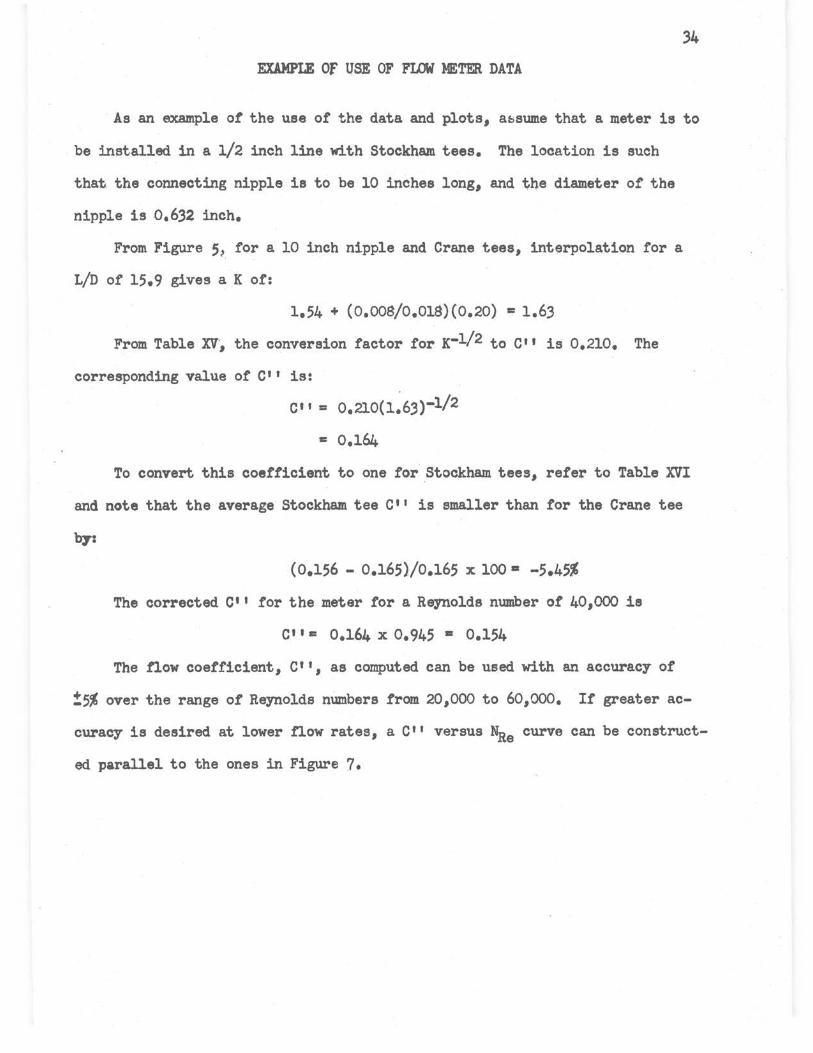
EXAMPLE Of USE OF FLOW METER DATA
As an example of the use of the data and plots, atssume that a meter is to
be installed in a 1/2 inch line with Stockham tees. The location is such
that the connecting nipple ie to be 10 inches long, and the diameter of the
nipple is o.632 inch.
From Figure 5,. for a 10 inch nipple and Crane tees, interpolation for a
L/D of 15.9 gives a K of:
1.54 + (o.oos/o.01s)(o.20) • i.63
From Table xv·, the conversion factor for K-1/2 to c•' is 0.210. The
corresponding value of C'' is:
c•, = 0.210(1.63)-1/2
To convert this coefficient to one for Stockham tees, refer to Table XVI
and note that the average Stockham tee C'' is smaller than for the Crane tee
( 0el56 - 0.165)/0.165 X 100 • -5.45%
The corrected c•• for the meter for a Reynolds number of 401000 is
Cl I= 0.164 X 0.945 • 0.154
The fiow coefficient, c••, as computed can be used with an accuracy of
?5% over the range of Reynolds numbers from 201000 to 60,000. If greater ac
curacy is desired at lower now rates, a 011 versus Nae curve can be construct
ed parallel to the ones in Figure 7.

35
FUTURE WORK
Further work with this type of meter would appear to be desirable. It
was noted that the second general arrangement in which the flow enters the branch
or the impact tee was less influenced by variables in sections 3 and 4. This
would indicate that a meter constructed such that the flow enters the branch
of both tees would not be as sensitive to variations in pipe fitting size and
assembly as the standard arrangement which has been studied.
Another type of meter could be formed trom the cross titting. Here the
two pressure taps would be inserted in the two extra openings. The diagrams be
low illustrate the two types of meters mentioned.
Meter with Flow Into
Branch of Both Tees
t D
to manometer ~, CJ
D D ~[~f ..... l et_e_r __.I Ur===JO
0 t
Flow Meter from
Cross Fitting

36
NOMENCLATURE
A Pipe cross sectional area, feet2
C Linear now coefficient, d~ensionless
C1 Volumetric now coefficient, gallons...seconds/minut•-feet
C'' Volumetric flow coefficient, gallons-seconds/minute (feet-inches)l/2
D
g
H
K
Diameter of pipe, feet
Conversion factor, pounds ~ss-feet/seconds2-poundJ force
Head, feet of' fluid flowing
Velocity head coefficient, dimensionless
~e Reynolds number
Q Volumetric rate of' now, g~lons/minute
R Manometer differential, inches of carbon tetrachloride-water
T Temperature, °F
V Linear velocity in pipe, feet/second
v Weight rate of flow, pounds/minute
.p Density, pounds/ f eet3
JJ.. Viscosity, pounds/second-feet
EQUATIONS
K • 2gl::i.H/V2
C • V/-J2g6.H
c• !Ii~
C' t = Q/V2gR

APPBNDIX
SAMPia CALCULATIOIS
Calculations tor 1 inch tees.
1. Calculation ot the velocity head coetficient, K.
V •#/minx min/sec x rt.3/1, x l/rt2 • ft/sec
• W X 1/60 X 1/62.4 X l/(1!~49)2(0.785)
= 0.0446 w
6.H • R/12 x (Sp. G. CCl4 - Sp. G. H20) Sp. G. H20
= R/12 x (1,584 - 1,0) 1.0 = 0.0487 R
I 111 2g x aH/Vf' 2
• 64.4 x o.~ R/(0.0446 w)
= .3.13 R/(0.0446 w)2
For run 771, w = 42.5 R • 2.1
2 K = .3el.3 X 2.1/(0.0446 X 42.5)
• 1.82
2. Calculation or Reynolds number, Nae•
NRe • DVf' /µ,
For run 771, D • 1.049 (Ret. No. 8) V • 0.0446 X 42.5 = 1.895 ,P = 62.4 jJ. • 1 • .3 cp (Ret. No. 6)
IL. 111 1.049/12 X 1.895 X 62.4 ""Ke 1 • .3 X 0.000672
• 11,800
37
.3. Calculation ot the flow rate coefficient, C1 1 , from experimental data.
Cl I s: Qj..../2i,R
where Q • w/8 • .3.3 tor run 771, w • 42.5, and R • 2.1
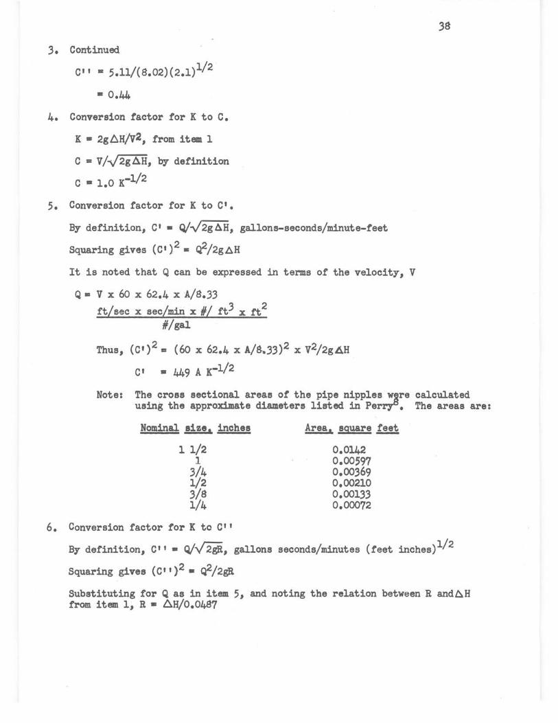
3. Continued
c11 • 5.11/(s.02)(2.1)1/ 2
• o.44.
4. Conversion factor for K to c. K • 2g4H/v2, from item 1
C = v/-J2gll.H, by definition
C • 1.0 K-l/2
5. Conversion factor for K to c•. By definition, c• • Q/~, gallons-seconds/minute-feet
Squaring giv$s (c')2 • ci2/2gt::,.H
It is noted that Q can be expressed in terms of the velocity, V
Q • V X 60 X 62.4 X A/8.33 ft/sec x sec/minx#/ ft3 x tt2
#/gal
Thus, (c')2 • (60 x 62.4 x A/8.33)2 x v2/2gAH
C1 • 449 A K-l/2
38
Note: The cross sectional areas of the pipe nipples w~re calculated using the approximate diameters listed in Perry°. The areas are:
Nominal size, inches
11/2 1
3/4 1/2 3/a 1/4
6. Conversion factor for K to C11
Area, square ~
0.0142 0.00597 0.00369 0.00210 0.00133 0.00072
By definition, C1 1 • Q/.../'2ij., gallons seconds/minutes (feet inches)1/ 2
Squaring gives (C" )2 • r:[2/2gJ1
Substituting for Q as in item 5, and noting the relation between R and~H f'rom item 1, R • 6H/0.0487

6. Continued
(c 1 , ) 2 s (60 x 62.4 x A/s.33)2 x v2/(2gAH/o.o4S7)
(C 11 ) • (60 x 62.4/8.33)(0.0487)1/2 A K-1/2
• 99 A K-1/ 2
The cross sectional areas are listed under item 5.
39

TOI& MI -nTTm DiglSIOIS Cit AQTUAL DASllUIIIIT)a
Tee Diaenaion, inches B£M4 Sise !2a... A ....L C D 11: r - - - - - -Crane l 1/2 l 1,94 2,41 1,84 2,06 0.1s 2,18 Stockham " l " 2,'4.7 1,97 1.91 11 "' It " 2 " " " 1,93 .. " 'Walworth " l It 2.41 1,84 1,87 .... " Crane l l l,45 1,70 1,28 1,34 0,65 1.,,
" " 2 " 1,72 " " 0.63 l,S6 " " 3 l,'4,8 1,68 1,22 . 1,25 0,65 1,60
Detroit II l II l,S9 ·l,24 1,21 0 •. 75 .1,44 " " 2 " 1.,2 1,19 . 1,22 " ' " Crane 3/4 l 1,30 1,53 1,08 l,J.O o.6J l,31 " " 2 ·" 1.,0 " " 0,65 fl·
" n ., If 1,4,8 1 •. 06 1,08 0,,67 " Stoolcbla " l 1,28 1,47 1,05 1,06 0,62 1.2,
" " 2 • n • a " 1,22 • "' ' " 1.,0 1.0, " N ' "
Cl'UII 1/2 1 1,13 1,33 o.a, 0,83 0,56 1,10
" " 2 " .. 0,84 0,84 " 1,09 Stookham " 1 1,10 1,31 0,8'7 0,87 0,55 1,.06
" " 2 " l,.30 " • N· " " 3/8 l 0,95 1,03 0,-67 o.,, 0.44, 0,$6 " " 2 " 1.07 " 0,72 " 0,.94 • Iii 3 " " 0,69 0,71 " 0,84
Detl'Oit " l 0,97 .i.oo 0,61 0,62 0,4; . 0,87 " II 2 " . 1,02 It 0,66 " 0,83 " 1/4 l 0,805 o •. 66 0,52 O,S6 0,47 o.62 " " 2 n " II " 0,46 0,-63 " " 3 " " 0,51 O,Sl 0,45 "'
a Dimensions lettered on the cro111-sectional views shown below
, I

TABLE XVIII
EXPERIMUTAL AND CALCULATED~
(Values of the variables investigat,ed in each of these tables are given in the corresponding sUJlllll&ry -tables in the text, Tables I, Ill and nv.)
- - -
(1) Length of calming section, ~ arraniaaent (2) Continued "ii Nae - . e
Bun v B V K x 10-.3 T Run V R V ....L X 10-3 T - - - - -63.3 72.0 5.65 .3.2 1.72 19.2 48 68.3 94.5 10.7 4.21 1.89 29 • .3 57
4 109.0 12.9 5.29 1.72 31.8 4 112.5 15.0 5.00 1.88 34.8 5 1.36.5 20 • .3 6.06 1.70 36.4 5 126.5 19.2 5.64 1.89 .39.2 6 149.0 24.0 6.62 1.69 .39.7 6 1.38.5 2.3.5 6.17 1.92 42.2 7 71.0 6.o 3.16 1.85 19.0 7 15.3.0 27.4 6.81 1.85 47.4 8 108.5 1.4.8 5.26 1.99 31.6 8 158.0 29 • .3 7.05 1.85 49.0 9 1.36.5 2.3.0 6.06 1.92 .36.4 9 42.2 2.4 1~88 2.49 1.3.1
40 149.5 27.9 6.64 1.95 39.8 .390 60.5 5.0 2.10 2.14 18.8 1 72.5 5.9 3 • .32 1.77 19.4 1 74.0 6.9 .3 • .30 1.98 22.9 2 110.0 13.9 4.89 1.80 29.4 2 95.0 11.5 4.2.3 2.00 29.4 3 1.37.0 21.2 6.09 1.78 .36.6 .3 111.0 14.5 4~95 1.98 34.5 4 151~0 25 • .3 6.72 1.75 40/3 4 126.0 21.2 5.61 2.10 39.0
5 140.0 25.0 6.24 2.01 4.3.4 (2) Distance between straightening!!!!! end 6 152.0 29~5 6.76 2.01 47.0
and impact!!! - ·
(3} Angle~ calming section _!!:!!! h.clrizontal .360 .30.2 1.1 1 • .35 1.89 9.4 57
1 4.3.2 2.1 2.1 1.76 1.3.4 751 74.5 5.5 3.32 1.55 20.1 44 2 59.7 4.3 2.66 1.89 18.5 2 112.0 12.0 4.98 1.51 .30.1 3 72.5 6.3 3.24 1.9.3 22.7 .3 141.5 18.5 6.jo 1.46 38.0 4 94.0 10.6 4.19 1.88 29.1 4 15.3.0 21.5 6.80 1.47 41.0 5 lll.5 14.9 4.96 1.88 34.5 5 76.o 5.6 3 • .38 1.5.3 20.5 6 125,.0 19.1 5.-;g 1.92 3s.a 6 112.0 12.1 -4.98 1.51 30.3 7 137.5 23.5 6.13 1.96 42.6 7 1.39.0 18.4 6.19 1.51 37.4 8 152.0 27.9 6.7s 1.90 47~1 8 151.0 21.9 6.72 1.51 40.6 9 15s.o 29.6 1.05 1.87 49.0 9 76~0 5.7 3.38 1.54 20.5
80 41~2 2.0 1.8.3 1.87 12.7 so 111.5 11.s 4.96 1.50 .30.0 1 61.7 4.4 2.16 1.8.3 19.2 1 1.38.5 18.1 6.16 1.49 37 • .3 ~
2 7.3.2 6.5 .3.26 1.90 22.6 2 152.5 21.s 6.79 1.49 41.1 ~

DBm IVIll _(Cont.)
(4) End of nipple reamed~ kl! incheslile c 6 > contimlecf . ·x~~3 Run w Jl V K x 10-.3 T Run 1f R _!_ .K T - ------ -
701 7.3.0 5.8 .3.25 1.70 19.6 45 6o.3 139.5 20.2 6.21 1.64 35.4 48 2 no.o 13.1 4.92 1.69 29.6 4 153.0 24.8 6.81 1.67 38.7 3 140.5 20.7 6.25 1.65 .37.7 &)9 74.5 6.2 3 • .32 1.76 18.9 4 151.0 24.-2 6.72 1.67 40.5 10 lll.5 1.3.0 4.96 1.65 28.3
719 75.5 6.2 3 • .36 1.72 20.2 1 1.39.5 20.8 6.21 1.69 .35.4 20 113.5 13.7 5.05 1.67 .30.4 2 152.0 · 24.5 6.76 1.66 38.5 1 140.0 20.9 6.2.3 1.68 37.6 .3 74.0 6.o .3.30 1.12 18.8 2 152.5 24.5 6.79 1.67 40.9 4 ll0.5 13.9 4~92- 1~79 38.0
5 138~0 20;5 6.40 1.70 36.5 (5) Threading ~ section ~ 6 150.5 25.0 6.69 1.74 .38.0
7 74.0 5.7 .3.-30 1.63 18.8 723 75.0 6.J J.34 1.74 20.1 45 "' 8 lll.O 12.9 4.94 1.65 28.2
4 112.0 13.9 4.98 1.75 30.0 :9 136.0 19.8 6.06 1.68 34.5 5 142.0 21.6 6 • .32 1.69 .38.1 20 152.0 23.1 6.76 1.58 .38.6 6 151.0 25.1 6.71 1.74 40.5 1 75.5 5.5 3 • .36 1.52 19.1 7 73.5 6.1 3.28 1.77 19.8 2 uo.o 12.0 4.89 1.56 27.8 8 112.0 13.4 4.98 1.69 30.0 .3 1.39.0 19 • .3 6.21 1.56 .35.4 9 139.5 20.6 6.20 1.69 .37.3 4 151.0 22.5 6.72 1.56 .38 • .3
30 152.0 25.1 6.74 1.11 40.6 5 41.0 4.7 . 2.95 1.68 13.0 44 1 74.5 6.2 .3 • .32 1.76 20.0 6 6o.o 9.1 4 • .32 1.50 19.1 2 lll.O 12.7 4.94 1.75 29.7 7 88 .. 0 19.0 6 • .34 1.48 28.o 3 139.5 21.2 6.21 1.72 37.4 8 107.0 27.3 7.69 1.44 .34.0 4 152.0 25.3 6.76 1.72 40.6 9 41.0 4.7 2.95 1.69 13.0
temperature 45 F. 30 68.5 10.8 4.93 1.-38 21.s ... 1 89.0 19 • .3 6.4 1.47 28.3
(6) Brands of Tees--Crane 2 105.5 27~1 7.59 1.48 33.5 -- 3 43.0 4.3 3.09 1.40 1.3.6 605 73.5 5.8 3.28 1.68 18.7 48 4 65.5 11~4 4.71 1.6o 20.s
6 111.5 13.0 4.96 1.65 28 • .3 5 88.5 20.8 6 • .36 1.57 28.1 7 138.0 20.6 6.14 1.11 .35.0 6 106.0 28.4 1.62 1_.5.3 3.3.7 r 8 151.5 2.3.9 6.74 1.6.3 .38.4 7 4.3.5 4.7 3.13 1.54 13.s
601 72.5 5.9 J.~3 1.76 18.4 8 66.5 11.4 4.78 1.56 21.2 h 2 110.5 13.1 4.92 1.69 38.0 9 89.5 20.0 6.44 1.51 28.4

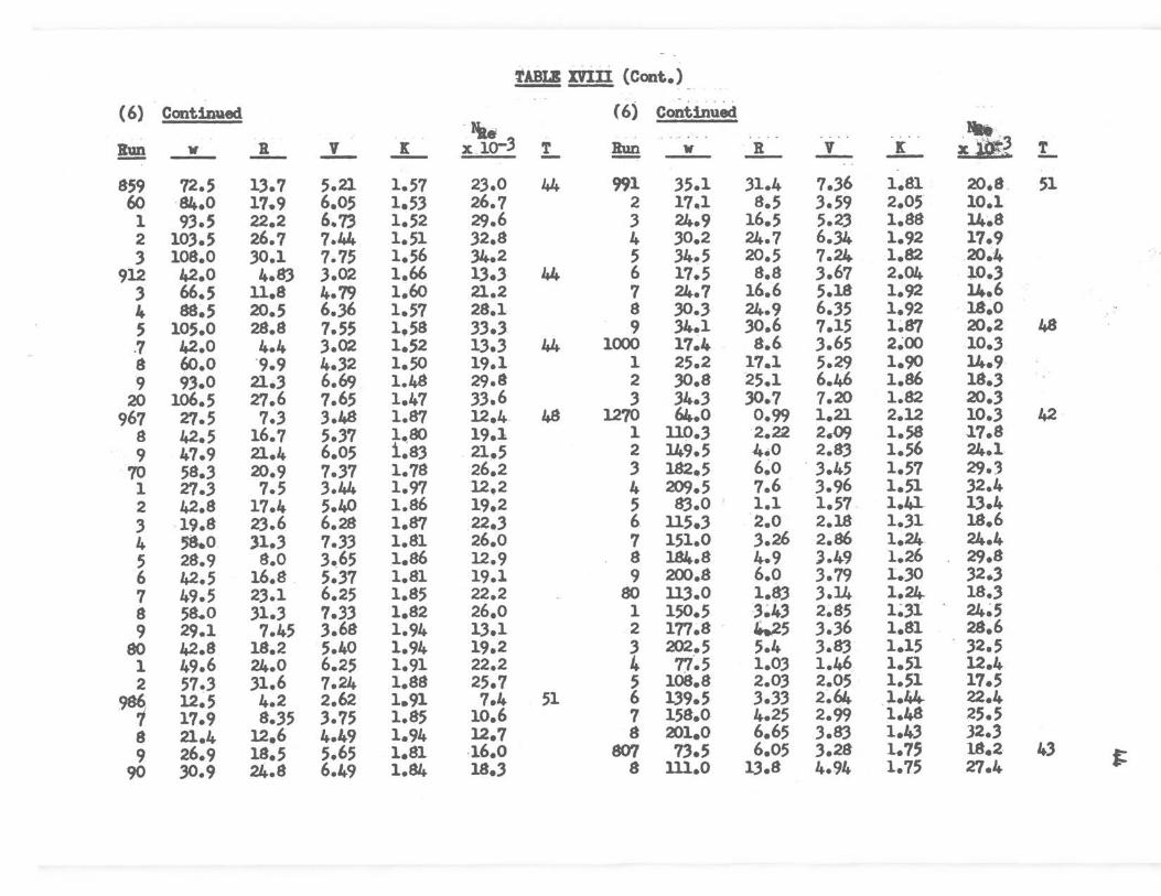
TABLE XVIII (Cont.)
(6) Continued ( 6) Continued 1il. .. -~
~ - w .A_ ..L ...L X l0-3 T !!!!! w R ...L .L X 10-3 !.. -940 106.0 28.4 7.62 1.53 33.5 44 1016 6.3 4.6 2.32 2.66 5.W. 51
1 25.3 5.5 3.20 1.70 11.0 46 7 8.7 7.9 3.21 2.38 &~9S 2 36.5 9.9 4.62 1.45 15.8 8 13.2 17.3 4.88 2.26 .. , 3 43.6 15.6 5.51 1.60 18.9 9 16.2 24.6 5.96 2.18 ~9 4 49.5 21.1 6.26 1.68 21.5 20 18.2 30.4 6.71 2.u 14.5 5 60.o 20.7 7.60 1.66 26.0 1 8.97 s.3 3.32 2.34 7.2 6 23.5 5.0 2.97 1.77 10.2 2 13.2 16.7 4.89 2.17 10.6 7 31.2 8.9 3.45 1.78 13.6 3 16.3 24.9 6.03 2.14 1.3.1 8 43.5 16.3 5.50 1.68 18.9 4 1s.o 30.5 6.65 2.15 14.4 9 56.5 23.4 7.15 1.46 24.4 5 8.77 7.9 3.24 2.35 7.04 48
50 60.o 30.9 7.59 1.67 26.0 6 13.1 16.8 4.84 2~24 10.5 1 31.2 9.5 3.95 1.89 13.6 7 16.2 25.0 5.99 2U7 13.0 2 44.0 16.2 5.56 1.63 19.l 8 17.7 30.3 6.74 2.20 14.2 . 3 52.2 23.2 6.60 1.68 22.7 9 8.4 7.9 3.ll 2.55 6.74 4 60.5 30.5 7.65 1.63 26.2 30 ~.12.4 16.5 4.58 2.35 9.9 5 31.8 9.2 4.02 1.78 13.8 1 15~7 24.7 5.78 2.30 12.5 6 42.2 16.3 5.33 1.78 18.3 2 17~2 30.7 6.34 2.37 13.7 7 52.5 ,24.1 6.64 1.71 22.8 3 8.6 8.1 3.16 2.52 6.9 8 59.5 31.1 7.53 1.71 25.8 4 12.5 17.0 4.59 2.52 10.0
841 74.0 5.9 3.30 1.69 18.5 43 5 15.7 25.2 5.78 2.35 12.5 2 109.5 13.2 4.87 1.74 21.2 6 16.8. 30.s 6.23 2.35 13.5 3 137.0 21.3 6.10 1.79 34.2 g 47.3 o.60 0.89 2.36 7.5 42 4 151.0 25.4 6.72 1.75 37.6 9 112.3 1.96 2.12 1.36 18.0
629 72.0 5.9 3.21 1.79 18.0 60 1.41~0 3.06 2.65 1.36 22.5 30 112.0 13.6 4.98 1.70 27.9 1 160.3 3.95 3.10 1.29 26.4 1 141.0 20.5 6.27 1.64 34.1 2 181.5 4.73 3.42 1.26 29.0 2 152.5 24.6 6.80 1.66 38.1 3 198.8 5.85 3.74 1 .. 30 .31.7
1008 17.8 8.7 3.72 1.96 10.9 51 4 62.3 0.76 1.18 1.72 10.0 42 9 24.5 15.9 5.14 1.88 15.0 5 109.0 2.05 2.07 1.49 17.7
10 30.9 24.7 6.48 1.83 19.0 6 133.8 .. 3 • .30 2.53 1.61 21.5 1 35.1 31 • .3 7.35 1.81 21.5 7 152.8 ·z.so 2.89 1.42 24.5 2 i6.7 s,1 3!49 2.07 10.4 8 1.78 •. 5 .90 .3.38 1.33 28.7 .3 25:2 17.4 5~28 1.95 15.5 9 209.5 6.85 4.00 1.34 .34.0 ti 4 .31.1 25.5 6.52 1.87 19.1 857 42.2 4.6'1 3.1..J 1.49 1.3.8 44 5 33.4 30.4 7.00 1.94 20.5 8 59.7 9.50 4.30 1.59 19.0
TABLB m:ri {Cont.)
{6) Continued (6) Continued -1ae - ·.3 Run If R V I x .10-.3 T Run If ...!L ..L. ..L xlO;t;a,, T - - - - - - -..
859 72.5 13.7 5.21 1.57 2.3.0 44 991 35.l .31.4 7 • .36 1.81 20.s . 51 60 ·81+.0 17.9 6.05 1.5.3 26.7 2 17_1 8.5 .3.59 2.05 10.1 1 9.3.5 22.2 6.73 1.52 29.6 3 24.9 16.5 5.23 1.88 14.8 2 103.5 26.7 7.44 1.51 32.8 4 30.2 24.7 6.34 1.92 17.9 .3 108.0 30.1 7.75 1.56 34.2 5 34.5 20.5 7.24 1.82 20.4
912 42.0 4.83 3.02 1.66 1.3 • .3 44 6 17.5 8.8 .3.67 2.04 10 • .3 .3 66.5 11.8 4.79 1.60 21.2 7 24.7 16.6 5.18 1.92 U..6 4 88~5 20.5 6.)6 1.57 28.1 8 30 • .3 24.9 6 • .35 1.92 18~0 5 105.0 28.8 7.55 1.58 .3.3 • .3 9 34.1 30.6 7.15 1~87 20.2 48 .7 42.0 4.4 .3.02 1.52 1.3 • .3 44 1000 17~4 8.6 .3.65 2~00 10 • .3 8 60.o ·9.9 4 • .32 1.50 19.1 1 25.2 17.l 5.29 1.90 14.9 9 9.3.0 21 • .3 6.69 . 1.48 29.8 2 30.8 25.1 6.46 1.86 18 • .3
20 lo6.5 r,.6 7.65 1.47 .3.3.6 .3 .34 • .3 30.7 1.20 1.82 20 • .3 967 r,.5 7 • .3 3.48 1.87 12.4 48 1270 64.0 0.99 1.21 2.12 10 • .3 42
8 42.5 16.7 5 • .37 1.ao 19.1 1 no • .3 ·2.22 2.o9 1.58 J.7.8 9 47.9 21.4 6.05 i~83 21.5 2 149.5 4.0 2.8.3 1.56 24.1
70 58 • .3 20.9 7 • .37 1.78 26.2 .3 182.5 6~0 . .3.45 1.57 29.3 1 27 • .3 7.5 .3.44 1.97 12.2 4 209.5 7.6 .3.96 1.51 .32.4 2 42.8 17.4 5.40 1.86 19.2 5 83.0 ' 1.1 1.57 1.4].. 1.3.4 .3 19.8 2.3.6 6.28 1.87 22 • .3 6 ll5 • .3 2.0 2.18 1 • .31 18.6 4 58.0 31.3 7.3.3 1.81 26.0 7 151.0 3.26 2.86 1.24 24.4 5 28.9 8.0 .3.65 1.86 12.9 8 184.8 4.9 .3.4-9 1.26 29.8 6 42.5 16.8 5 • .37 1.81 19.1 9 200.s 6.o .3.79 1. .. 30 .32 • .3 7 49.5 2.3.1 6.25 1.85 22.2 80 ll.3.0 1.8.3 .3.14 1.24 18 • .3 8 58.0 .31 • .3 7 • .3.3 1.82 26.0 1 150.5 .3~4.3 2~85 l~.31 24~5 9 29.1 7.45 .3.68 1.94 1.3.1 2 177.8 · 4.25 .3 • .36 1.81 28.6
80 42.8 18.2 5.40 1.94 19.2 .3 202.5 5.4 .3.83 1.15 . .32.5 1 49.6 24.0 6.25 1.91 22.2 4 77~5 1.0.3 1.46 1.51 12.4 2 57 • .3 .31.6 7.24 1.88 25.7 5 108.8 2.0.3 2.05 1.51 17.5 9, 12~5 4.2 2.62 1.91 7.4 51 6 1.39.5 .3 • .3.3 2.64. 1.44- 22.4
17.9 8 • .35 .3.75 1.85 10.6 7 158.0 4.25 2.99 1.48 25.5 8 21.4 12.6 4.49 1.94 12.7 8 201.0 6.65 .3.83 1.4.3 32 • .3 9 26.9 18.5 5.65 1.81 -16.0 807 7.3.5 6.05 .3.28 1.1, 18.2- 4.3 I=
90 30.9 24.8 6.49 1.81+ 18 • .3 8 lll.O 1.3.8 4.94 1.75 27.4
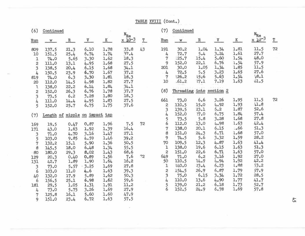
TABLE XVIII (Cont.)
(6) Continued (7) Cont.inued Hae Na~
~ w R V K x .19:3 T !!!!!! w R V K tlo-3 T - -809 137.5 21.3 6.10 1.78 33.8 43 191 30.2 1.04 1.34 1.81 11.5 72 10 151.5 25.4 6.74 1.74 37.4 4 72.7 5.4 3.24 1.61 27.7 1 74.0 5.65 3.30 1.62 18.3 7 ~25.7 15.4 5.60 1.54 48.0 2 111.0 13.1 4.95 1.68 27.5 9 152.0 22.1 6.76 1.54 57.9 3 138.5 20.1+ .6.15 1.68 34.1 201 30.0 1.05 1.31+- 1.85 11.5 4 150.5 23.9 6.70 1.67 37.2 . 4 72.5 5.5 3.23 1.65 27.6
819 74.0 6.3 3.30 1.81 18.3 7 l26.2 L5.6 5.63 1_.54 '..S.l 20 ll2.0 14.5 4.98 1.82 27.7 10 :..61.2 ~7.1 7.19 1.6.3 01.5
l 138.0 22.2 6.14 1.84 34.1 -..
2 152.0 26.3 6.76 1.78 37.7 (8) Threading -into seet.ion .~ 3 73.5 6.2 3.28 1.80 18.J 4 111.0 14.4 4.95 1.83 27.5 661 73.0 6.6 3.26 1.95 ll.5 72 5 152.0 25.7 6.75 1.75 37.6 2 ll0.5 15.0 4.92 1.93 U.8
3 139.5 23.1 6.2 l.87 52.6 (7) Length of nipple .2!! impact ~ 4 152.0 ~7.0 6.75 1.84 57.4
5 73.5 5.8 3.28 1.68 27.8 169 19.5 0.47 0.87 1.96 7.5 72 6 u2.o 13.0 4.-98 1.63 42.4 171 43.0 1.63 1.92 1.39 16.4 7 138.0 20.1 6.15 _.66 51 • .3
3 71.0 4.70 .3.16 1.47 27~1 8 151.0 24.J 6.71 1.68 57.0 5 103.0 9.85 4.59 1.46 39.2 9 74.5 5.6 3.32 1.-59 28.2 7 1.32.2 15.1 5.90 1 • .36 50.5 70 109.5 ·12.3 4--fr/ 1.63 41.4 8 145.5 18.0 6.48 1.34 55.5 1 1.38.0 19.6 6.15 1.6.3 51.3
80 180.0 29.3 8.02 1.43 68.6 2 151.0 22.6 6-.71 1.6.3 57.0 129 20.J 0.40 0.89 1.56 7.6 72 649 71.0 6.2 J.16 1.92 27.0 1.31 42.7 1.89 1.90 1.64 16~2 50 110.5 14-.-9 ,.._94 1.92 42.2
3 73.0 5.57 · 3.25 1.69 27.8 1 u .. o.o 23.4 6.2.3 1.88 5.3.2 6 103.0 u.o 4.6 1~63 39.3 2 154.5 26.9 6.87 1.79 57.9
40 132~0 17.9 5.89 1.62 50.3 3 75.0 6.15 J.34 1.72 28.5 6 156.5 25.1 6.98 1.62 59.6 4 uo.o 13.6 4.90 1.77 41.7
181 29.5 1.05 1.31 1.91 11.2 5 139.0 21.2 . 6.18 1.73 52.7 4 73.0 5.75 3.26 1.69 27.9 6 152.5 24 •. 9 6.78 1.69 57.8 7 125.8 16.1 5.60 1.60 47.9 9 151.0 23.4 6.72 1.6.3 57.5 ,I:-
"'
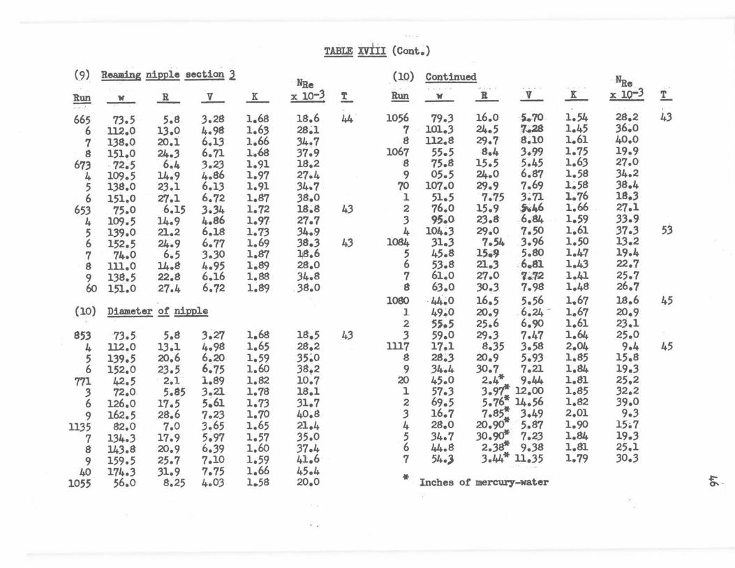
TABLE MII (Cont.-)
(9) Reaming nipple section J. (10) Continued Nile ·Nile !!!!! 1f 1l V K X 10-j t Run V .lL _!_ ...L X 10-3 T - - - - - --- - ' 665 73.5 5.8 3.28 1.68 18.6 44 1056 79.3 16.0 -5..70 1.54 28.2 43
6 112.0 13.0 4.98 1.63 2Sa 7 101.3 24.5 7~ 1.45 36.o 7 138.0 20.1 6.13 1.66 34.7 8 112.8 29.7 8.10 1.61 40.0 8 151.0 24~3 6.71 1-..-68 37~9 1067 55.5 8.4 3.99 1.75 19.9
673 -72~5 6.4 3.23 1.91 18.2 8 75.8 15.5 5.45 1.63 27.0 4 109.5 14.9 4.86 1.97 27.4 9 05.5 24.0 6.87 1.58 34.2 5 138.0 23.1 6.13 1.91 34.7 70 107.0 29.9 7.69 1~58 36.4 6 151.0 27.l 6.72 1.87 38.o 1 51.5 . 7.75 3~71 1-.76 18.3
653 75.0 6~15 3.34 1.72 18-.8 43 2 76.o 15.9 ~46 1.66 27.1 4 109.5 14.9 4.86 1.97- 27.7 3 95~0 23.8 .6.84 1.59 33.9 5 139.0 21.2 6.18 1.73 34.9 4 104~3 29.0 7.50 1.61 37.3 53 6 152.5 24.9 6.77 1.69 38.3 43 1084 31.3 7.54 3.96 1.50 13.2 7 74.0 6.5 3.30 1.87 18 6 5 45.8 15 .• 9 5.80 1.41 19.4
' . 8 lll.O 14.8 4.95 1.89 28.0 6 53.8 21-., .6~81 1.43 22.1 9 138.5 22.8 6.16 1.88 34'118 7 61.0 21.0 ·,-.12. 1.41 25.7 60 151.0 27.4 6.72 1.89 38.o 8 63.0 30.3 7.98 1.48 26.7
1080 .44-.0 16.5 5.56 1.67 18.6 45 (10) Diameter of nipple 1 49~0 20~9 . 6.24 - 1-.67 20.9
2 s~.s 25.6 6.90 1.61 23.1 853 73.5 5.8 3~27 1~68 18~5 43 3 59.0 29.3 7.47 1.64 25.0
4 112.0 13.1 4.98 1.65 28.2 lll7 17.1 8.35 3.58 2.04 9.4 45 5 139~5 20.6 6.20 1.59 35~0 8 28-.3 20.9 5.93 1.85 15.8 6 152.0 23.5 6~75 1.60 38,2 9 34.4 30.7 7.21 1.84 19.3
771 42.5 - 2.1 l.89 1.82 10.7 20 45.0 2.~ 9.44 1.81 25~2 3 72.0 5.85 3.21 1.78 18.1 1 57.3 3. 12.00 1.85 32.2 6 126.0 17.5 5~61 1.73 31.7 2 69.5 5.76* 14.56 1.82 .39.0 9 162.5 28.6 7.23 1.70 40.8 3 16.7 7.85: 3.49 2.01 9.3
1135 82.0 1.0 3.65 1.65 21.4 4 28.0 20.90 . · 5.87 1.90 15.7 7 134.3 17.9 5.97 1.57 35.0 5 34.7 30.~ 7.23 1.84 19.3 8 143.8 20.9 6 • .39 1.60 37.4 6 44.8 2 • .38* 9.38 1.81 25.1 9 159.5 25.7 7.10 1.59 41.6 7 54~> 3.44* 11.35 1.79 30.3
40 174.3 31.9 7.75 1.66 45.4 ·- --
* 1055 56.o 8.25 4.03 1.58 20.0 Inches ot mercury-water ,I:-
°' -

TABLE xv,ili ~~ont.. )-
(ll) Hipple length ·Nile
(11) Cont.1nued ··Hae .. .
Run w R V K X 10•.3 T llun . w ·R V I( x 10-.3 !... -- - - - - - · - - -.. - ' ns 74.5 5.65 3 • .32 1.61 Ul;f 45 ll05 16~-<J 8~59 3~54 2.13 10.0 49 6 11l.O 12.8 4~9S 1.64 28.2 6 26~7 20~8 . 5.60 2.08 15.8 7 1.39.0 20.0 6.18 1.6.3 .35.2 7 .3.3.2 31.5 6.95 2.·04 19.6 8 152.0 2.3.7 6.77 1.61 38.7 8 40 .. 5 2.23: 8.49 2.00 2.3.-9 9 75.0 6.45 .3 • .34 1.80 19~0 9 54.8 4.06.., 11.48 2.06 .36.4
40 112.5 1.3.8 5.00 1.72 28.4 10 69.7 6.40 14,.60 2.01 41.1 1 141.0 21.3 6.2, · 1.69 35.6 1129 68 • .3 6.05_ 3.04 2.05 18.8 2 151 • .5 25.8 6.74 1~77 .38~3 30 96.8 n.1 4.31 1.97 26.8
747 7.3 • .5 5 • .35 .3.2? 1.55 18.6 45 1 121.a 18.4 5.40 1.97 .3.3. 7. 8 lll.O 12.0 4.94 1.54 28.2 2 158 • .3 .30 • .3. · 7.04- 1.91 43.9 49 9 140.5 18.1 6.25 1.44 .35.5 3 164 • .3 1.58* . 7.31 1.97 45~6
' 50 151.5 21.8 6.74 1.49 . .38.2 4 · 174.8 1.69! 7.77 1.87 48.5 l~l 48.9 7~6 3.52 1.92 17.7 5.3 1217. 9.5 6.45 .3.51 1.63 6.8 45
4 70.0 1$.6 5.04 1~91 25.5 8 n.o. 16.3 4.06 .3.os 7.92 .5 89.0 24.1 6.40 1.83 32 • .3 9 15.5 23.2 5.72 2.22 11.1 6 99/3 29.6 7.14 1.82 .36.0 20 17.3 29.5 6 • .39 2.25 12.4
1089 27 • .3 7.6 3.45 1.99 u.5 44 1 22.9 1. 77*"_ 8.44 1.67. 16.4 90 41.5 16.9 5.25 1.92 17.5 2 25.9 * 2.24 18.6 3.04* 9.55 1 47.s 21~6 6.05 1.85 20.2 .3 .34.5 5 • .39 12.75 2.22 24 • .3 2 53.8 26 • .3 6.00 1.78 22.1 4 .38.1 8.2S: 1.4..10 2.4.3 27/3 .3 57 • .3 .31.1 7.25 .1.85 24~2 5 57~5 14.70 21 • .30 2.18 41~5 4 60.S 1.69* 7.66 1.93 25~6 6 10 • .3 0~67! 3.79 .3.10 7.4 5 84.1 .3.1.3: 10.62 1.86 .35 • .3 7 15.6 1 • .36 5.76 2.74 n.2 6 100.0 4 • .32 12.65 1.81 42.0 8 19.9 2.1~ 7 • .34 2.68 14 • .3 7 29 • .3 8.0 .3.71 1.81 12.4 9 28.8 4 42* 16 62 2.61 20.8 8 41.9 16~0.5 5 • .30 1.79 17.7 .30 .39.8 . * . 2.54 28.7 8.2.3 14.70 9 49.0 21.65 6.20 1.76 20.7 1 57.0 16.2.3* 21.10 2.45 41.2
1100 55 • .3 26.85 7~00 1.71 23.4 2 67.5 22.70! 25.00 2.4S 48.6 1 59 • .3 30.60* 7.50 1.70 25.0 3 10.6 0.70* .3.90 3.12. 7.6 2 61.0 1.57 7.72 4 15.l 1 • .33* 5.58 2.86 10.9 3 86.3 3.07 10.91 1.7.3 36 • .3 5 23.9 3.30* 8.83 2.84 17.2 4 10.3.0 4.22 · 13.03· 1.66 43.4 6 33.5 · .. --6·.-62• 12·.-40 2.88 24.2 * Inches of mercur;y-water * Inches ot mercury-water ~

TABLE XVIII (Cont.} . ..
( 11} Continued Nae
(13) continued Nae
Run " .JL ..J_ K X 10-3 T Run w R V K xl~3 !.. - - - -* '
1237 45~4 n.9s* 16.ao 2.85 32.7 45 545 72.5 5.35 3.23 1.59 19.7 50 8 59.0 17.25 21.80 3.43 42.5 6 109.0 ll.9 4~85 1.58 29.7 9 63.0 22.90: 23.30 2.85 45.5 7 140.0 17.8 6.23 1.43 38.1
40 9.8 o.65 .3.63 3.30 7.1 8 150.0 21.2 6.66 1.48 40.7 1 14.4 1.29! 5.33 2.04 10.4 9 72.5 4.85 3.23 1.44 19.7 2 23.2 3.04* 8.55 2.79 +6.7 50 112.0 11.1 4.97 1.40 30.4 3 33.7 6.42 12.5 2.75 24 • .3 1 1.38.0 16.9 6.13 1.40 37.5 4 46 • .3 ll.83* 17.1 2.7.3 33.4 2 150.0 19.6 6.66 1.37 40.7 5 55.2 16.40* 20.4 2.65 39.7 .3 72.5 4.7 3.23 1.40 19.7 6 6J.8 22.20* 23.6 2.68 46.o 4 no.5 10.9 4.91 . l.4(1 30.1:
5 1.38.5 16.7 6.15 1.37 37.6 (12) Reaming end·~ nipple into section ~ 6 151~0 19.9 6.71 1 • .38 41.1
·· * . -.. . . . .
1.76 (14) 515 72.0 5.8 3.21 19.8 50 Threading !!!!! _2! nipple ~ secti.OD 2 7 lll.O 13.4 4.95 1.71 30.4 9 1.38.0 21.1 6.14 1.75 .37.6 677 7.3.5 5.8 3~27 1.68 18.4 45
20 153.0 24.6 6.80 1.66 41.7 8 no.o 1.3.1 4.89 1.71 21.i.. 1 7?.. 'j 5.8 3.23 1.73 -19.8 9 1.38.5 20.2 6.15 1.66 34.6 2 m.o _-- 13 • .3 4.9.3 1.70 . .30.2 80 151.0 23.6 6.70 1.63 37.6 3 140.0 20.1 6.21 1.61 38.1 1 74.5 5.9 .3 • .31 1.68 18.6 4 152.0 23.6 6.76 1.61 41.5 2 110.0 13.2 4.89 1.Zt 27.4 5 71.5 5.8 3.19 1.76 19.5 .3 139.0 20.4 6.18 1~ 34.7 6 llJ.5 13.3 5.05 1.62 30.9 4 150.5 2.3~8 6.69 1~66 37.6 7 140.0 20.5 6.23 1.65 38.0 5 72.5 6.2 3.23 1.85 18.I 8 151.0 23.7 6.72 1.64 41.1 6 ll0.5 1.4.2 4.91 1.83 27.6
7 1.39.5 22.2 6.20 1.80 34.8 (13) Reaming ~ 2!_ nipple into section 2 · 8 152.0 26.3 6~75 1.79 .37.9
9 72.7 5.0 3.24 1.49 18.2 541 73.5 5.7 3.27 1.65 20.0 50 90 lll.O 11.8 4.93 1.50 27.7
2 ll0.5 12.7 4.91 1.6.3 .30.1 1 140.5 18.1 6.25 1.44 .35.1 3 138.0 19~5 6.13 1.61 .37.5 2 150.0 21 • .3 6.66 1.49 .37.4 4 152.0 23.5 6.75 1.60 41 • .3 3 73.0 5.7 3.25 1.68 18 • .3 * Inches ot mercur.,-water 4 109.5 13.1 4.87 1.73 27.J -,:,-
<»

TABIE XVIII (Cont.)
(14) Continued. (17) Threading bushing into section 6 lfae - - · Bile
!!!!! w .JL ..L I( X 10-.3 !... Run lf R ...L K X 10-.3 T - - --695 1.38.5 20.0 6.15 1.64 34.6 45 763 76.o 5.4 .3 • .39 1.49 19.1 44
6 151.0 2.3.6 6.70 1.6.3 .37.6 4 lll.O 11.s 4~94 1.51 28.1 7 7.3.0 5.8 3.25 1.70 18.3 5 139.0 18.3 6.19 1.49 .35.2 8 ll0.5 13.1 4.91 1.69 27.6 6 152.0 21.9 6.76 1.49 .38.6 9 1.39.5 20.5 6.20 1.66 .34.8 -- ---··
876 41.5 4.8 2.98 1.71 1.3.1 44 (18) Length ~ nipple., section 1 7 66.o 11.5 4.75 1.59 20.9 8 88.5 20.1 6.36 1.55 28.0 705 73.5 5.8 .3.28 1.68 18.7 45 9 107.0 28.7 1.10 1.52 34.0 6 U0.5 1..3.0 4.92 1.67 28.0
80 42.0 5.1 .3.02 1.75 1.3.3 7 1.38.0 20.3 6.15 1.69 35.0 1 66.5 ll.9 4.79 1.62 21.1 45 8 150.0 24.2 6.69 1.70 .38.0 2 88.0 '20.7 6 • .3.3 1.61 27~9 715 76.o 6.1 3 • .39 1.66 19.3 .3 105.5 29.2 7.5? 1.59 3.3.4 6 111.5 1.3.6 4.97 1.7.3 28.3 4 42.5 4.9 3.06 1.64 13.9 7 140.5 21.1. 6.2.5 1.68 35.6 5 66.o n.2 4.75 1~55 21~0 8 151.5 24.7 6.74 - 1.69 .38.4 6 89.0 18.9 6.40 1.44 28~2 45 7 1o6.o 26.0 7.61 1.40 3.3.6 (19} Threading section 1~ s~t.ion .2 8 4.3.5 5.4 3.1.3 1.72 1.3.8 ·--
9 65.5 ll.7 4.72 1.64 20.8 701 73.0 5.8 .3.25 1.70 18.6 45 90 88.0 20.4 6.33 1.59 27.9 2 no.5 1.3.1 4.92 1.6<} 28.1 1 105.0 28.7 7.55 1.58. .34 • .3 3 14() .. 5 20.7 -6~2-5 1~65 35.6
(15) Brands ot !!!!-tabulated under ill. 4 151.0 24.2 6.73 i.67 38.4
709 74.0 6 .• o 3.40 1.72 19.4 10 110.0 1.3.1 4.90 1.70 28.0
(16) Static iap 1 140.0 , 20.4 6.2.3 1.64 35.2
621 75.5 5.5 .3 • .37 1.52 20.1 48 (20) Reailing end.£! sectioa 1 2 no.o 12.0 4.9 1.56 29 • .3 ... .3 1.39.5 19.-.3 6.,20 1.56 .37~0 712 7.3.0 5.9 1.25 1.74 18.5 4 151.0 22~5 6.72 1 •. 56 40.2 .3 lll.5 1.3-.2 4.96 1./,7 28 • .3
629 7.3.0 5.5 .3.25 1.62 19.5 4 155.5 25.4 6.9 1.62 .39.3 .30 lll.O 12~6 4.94 1.61 29.6 1 138.5 20.1 6.15 1.65 36.9 -,:,-
2 152.0 2.3.0 6.76 1.57 40.6 '°
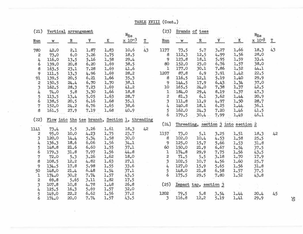
TABLE XVIll {Cont.}
(21) Vertical arrangement (23) Brands o! i~s -Nae Nite
Run w R V K x · io-3 T Run w · R · V · IC x lo-3 T - --- -- --- -780 42.0 2~1 1.87 l.83 10.6 43 1177 73.5 5.7 3~27 1.66 18.3 43
2 73.0 6.o 3.26 1.75 18.5 s 112.3 12.5 4.99 1.56 28.0 4 116.0 13.5 5.16 1.58 29.4 9 123.8 18.1 5.95 1.59 3J.4 6 139.0 20.8 6.20 1.69 .38.5 - 80 152.0 2.3.0 6.76 1.57 .38.0 8 163.5 2.3.1 7.28 1.69 41.6 1 177.0 30.1 7.86 1.52 44.1 9 lll.5 13 • .3 4.96 1.69 28.2 1207 87.8 6.9 3.91 1.42- 22.5
91 139.5 20.5 6.21 1.66 .35 • .3 8 116.5 12.1 5.19 1.40 29.9 ~ 150.5 24.4 6.70 1.70 .38.1 9 144.5 17.9 6.ltc.3 .1.34 37.0 .3 162.5 28.3 7.23 1.69 41.2 10 165.-5 24.0 7 • .38 1 • .37 42.5 4 74.0 5.8 .3~.30 1.66 18.8 L 184.0 29.4 8.19 1 • .37 47.3 5 ll3.5 13.4 5.05 1.6.3 28. 7 2 -81.3 6.1 3.62 1.44c 20.9 6 138.5 20.5 6.16 1.68 .35.1 3 lll.8 11.9 4.97 1.50 28.7 7 152.0 24.2 6. 76 1.65 38.6 4 140~8 18.1 6.25 1.44- .36.l 8 161.5 27.9 7.19 1.68 40.9 5 162.0 24.3 7.20 1.46 41.5
-- - - . ---. - . - . 6 179.5 30.4 .. 7.99 1.49 46.1 (22) Flow inio the i!! branch., Section !, threading .. . _ . . .. _ ~. : ~ .. . · . . . ~. -~. _ . . . . .
- - . {24) ThreadigS,. section l ~section~ ll41 73.4 5.5 .3.26 1.61 18 • .3 42 _
2 95.0 10.0 4.23 1.75 2.3.7 1157 73.0 5.1 3.25 1.51 18.3 42 .3 120~0 14.4 5 • .34 1.58 .30.0 8 102.0 10.4 4.5.3 1.58 25.5 4 1.36~.3 18.6 6 .. 06 1.56 34.1 9 125.0 15.7 5.66 1.53 31.8 5 148.8 21~6 6.60 1.55 37.l 6o 1.50.0 21.9 6.67 1.54 37.5 6 179 • .3 .31.8 7.97 1.56 41+.8 1 174.8 29.9 7.75 1..56 43.5 1 12.0 5.3 3.26 1.62 18.0 2 n.5 5 •. 5 3.18 1.10 17.9 8 108.5 12.2 4.82 1.63 27.1 3 102.5 10.7 4.56_ 1.60 25.7 9 1.34.5 17.8 5.98 1.55 33.6 4 127.0 15.9 5.65 1.56 31.8
50 148.o 21.4 ~48 1.54 37.1 5 1.48.o 21.a 6.;a 1.57 .37.5 1 174~0 30.2 7 •. 74 1.57 4.3.5 6 175.-5 29.5 1.so 1.52 43.8 2 69.8 5.65 3.11 1.82 17~5 .3 107.,8 10"8 4.78 1.48 26.8 (25) Impact !!2, seetion l 4 125.5 16.3 5.69 1.57 32.0 5 149.0 22.2 6.62 1.56 37.2 1202 79.5 5.8 3.54. 1.4.4. 20.4 45 6 174.0 20.0 7.74 1.57 4.3.5 .3 116.8 12.2 5.19 1.41- 29.9 ~
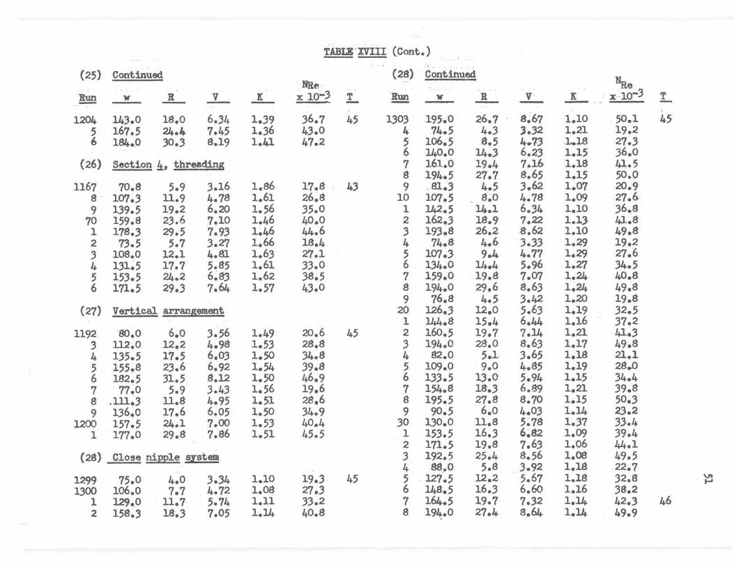
TABLE' XVIII (Cont.)
{25) Continued (28) Continued Hae · Nile ..
Run 'W R ..:J_ l X 10-3 T !!!!! 'W R .:L.. K x -10-3 T - - - - - - ·~-1204 143.0 1s.o 6.34 1 • .39 .36.7 45 1303 195.0 26.7 8~67 1.10 50.1 45
5 167.5 24.4 7.45 1 • .36 43.0 4 74.5 4.3 l.32 1.21 19.2 I, 184.0 .30.3 8.19 1.41 47.2 5 1o6.5 8.5 4-.7:J J ... 18 27.3
6 140.0 14.3 6.23 1.15 36.0 (26) Section!±, threading 7 161.0 19.4 7.16 1.18 41.5
8 194.5 27.7 8.65 1.15 50.0 1167 70.8 5.9 3.16 1.86 17.8 43 9 . 81.3 4.5 3.62 1.07 20.9
8 · 107 • .3 11.9 4.78 1.61 26.8 10 107.5 . 8~0 4.78 1.09 27.6 9 139.5 19.2 6.20 1.56 35.0 l 142.5 11,..1 6.34 1.10 36.8
70 159.8 2.3.6 1.10 1.46 40.0 2 162.3 18.9 1.22 1.1, 41.8 1 178.3 29.5 7.93 1.46 44.6 .3 193.8 26.2 8.62 1.10 49.s 2 73.5 5.7 3.27 1.66 18~4 4 74.8 4 .• 6 3.33 1.29 19.2 .3 108.0 12.1 4.81 1.63 27.1 5 107.3 9.4 4.77 1.29 27.6 4 131.5 17.7 5.85 1.61 33.0 6 134.0 14.4 5-.96 1.27 34.5 5 15.3.5 24.2 6~83 1.62 38.5 7 159.0 19.8 7.07 1.24 40.8 6 171.5 29 • .3 7.64 1.57 4.3.0 8 194.0 29.6 8.63 1.24 49.8
9 76.8 4.5 3.42 1.20 19.8 (27) Vertical. arrangement 20 126 • .3 12.0 5.63 1.19 32.5.
1 144.8 15.4 6.44 1.16 .37.2 1192 so.o 6.o 3.56 1.49 20.6 45 2 16o.5 19.7 7.14 1.21 41 • .3
.3 112.0 12.2 4.98 1.53 28.8 3 194.0 28.0 8.6.3 1.17 49.8 4 1.35~5 17~5 6.03 1.50 34.8 4 82.0 5.1 3.65 1.18 21.1 5 155.8 23.6 6.92 1.54 39.8 5 109.0 9.0 4.85 1.19 28.0 6 182.5 31.5 8.12 1.50 46.9 6 133.5 13.0 5.94 1.15 34.4 7 · 77.0 5.9 3.43 1.56 19.6 7 154.8 18.3 6.89 1.21 39.8 8 .111~3 11.8 4.95 1.51 28.6 8 195.5 27.8 8.70 1.15 50.3 9 136;0 17.6 6.05 1.50 34.9 9 90.5 6.o 1+.03 1.14 23.2
1200 157.5 24.1 7.00 1.53 40 .• 4 30 130.0 11.s 5~78 1.37 33.4 1 177.0 29.s 7.86 1.51 45.5 1 153.5 16.3 6.82 · 1.09 39.4
2 171.5 19.8 7.6S· 1.06 44.1 (28) Close nipple system 3 192.5 25.4 8.56 1.08 49.5
4 88. .• o 5.8 .. . .3.92 1.18 22.7 1299 75.0 4.0 3.34 1.10 19.3 45 5 -127.5 12.2. 5.67 1.18 32.8 "' .... 1300 106.0 7.7 4.72 1.08 27 • .3 6 148.5 16 • .3 6.60 1.16 38.2
1 129.0 11.7· 5.74 1.11 33.2 7 164.5 19.7 7.32 1.14 42.3 46 2 158~.3 18.3 7.05 1.14 40.8 8 194.0 27.4 s.64. 1.14 49.9

( 28) Continued
~ w R -1339 9i.o 6.1
40 122.0 12~3 1 155.5 17 • .3 2 172.5 21.3 3 193.0 27.4 4 94.5 6.9 5 129.0 12.6 6 156~0 18.8 7 .193.5 2s.2
....L ....L 4.10 1.1.3 5.4.3 1 • .30 6.91 1.1.3 7.66 1.13 8.58 1.16 4.21 1.21 5.74 1.19 6.94 1.22 8~60 1.19
TABLE XVIIl (Cont.)
Nae · X 10-3 I...
. .
2.3.7 46 31.4 40.0 44.3 49.6 24.4 .33.2 40.1 49.7
VI N

53
BIBUOGRAPHY
1. Freeman, J. H., The Flow of Water in Pipes and Fittings, Am. Soc. Mech. Engrs., 1941, 359 pages.
2. Hoopes, J. w., Isakorr, s. E., Clarke, J. J., and Drew, T. B., Chem. Eng. Progress, !tlt.,. 691, (1948).
3. Kroll, A. E., and Fairbanks, H. V., Ind. Eng. Chem.,~' 588-91, (1945).
4. Lapple, C. E., Chem. Eng., 2,2, 96-104, ( 194 9 )'.
5. Lansford, w. M., Univ. of Illinois Eng. Expt. Sta. Bull. No. 289, (1936).
6. McAdams, w. H., Heat Transmission, p.411, 2d Ed., McGraw-Hill, New York, 1942.
7. Nord, M., Chem. Eng., ZJ., No. 7, 113,- (1950).
8. Perry, J. H., Chemical Engineers• H1µ1dbook, p. 41!>. 3d Ed., McGraw-Hill, New York, 1950.
ADDRF.SSES OF MANUFACTURERS
1. Crane Company, 8.36 s. Michigan Avenue, Chicago 5, Illinois.
2. Detroit Brass and Malleable Iron Works, 100 s. Campbell, Detroit 9, Michigan.
3. Stockham Pipe Fittings Company, 4000 10th Avenue North, Birmingham Alabama.

THESIS TITLE: The Pipe Tee as a Flow Meter
NAME OF AUTHOR: Spencer Harlan Landes
THESIS ADVISER: Dr. Leo Garwin
The contPnt and form have been checked and approved by the author and thesis adviser. "Instructions for Typing and Arranging the Thesis" are available in the Graduate School office. Changes or corrections in the thesis are not made by the Graduate School office or by any committee. The copies are sent to the bindery just as they are approved by the author and faculty adviser.
NAME OF TYPIST: Opal Earl Jiles
*****************