The Multimodal Interaction through the Design of Data Glove · The Multimodal Interaction through...
129
The Multimodal Interaction through the Design of Data Glove By Bote Han A Thesis Submitted to the Faculty of Graduate and Postdoctoral Studies In Partial Fulfillment of the Requirements For the Degree of Master in Electrical and Computer Engineering Ottawa-Carleton Institute for Electrical and Computer Engineering School of Electrical Engineering and Computer Science Faculty of Engineering University of Ottawa Bote Han, Ottawa, Canada, 2015
Transcript of The Multimodal Interaction through the Design of Data Glove · The Multimodal Interaction through...
The Multimodal Interaction through the Design of Data
Glove
By
Bote Han
A Thesis Submitted to the
Faculty of Graduate and Postdoctoral Studies
In Partial Fulfillment of the Requirements
For the Degree of Master in
Electrical and Computer Engineering
Ottawa-Carleton Institute for Electrical and Computer Engineering
School of Electrical Engineering and Computer Science
Faculty of Engineering
University of Ottawa
Bote Han, Ottawa, Canada, 2015
ii
Abstract
In this thesis, we propose and present a multimodal interaction system that can provide
a natural way for human-computer interaction. The core idea of this system is to help
users to interact with the machine naturally by recognizing various gestures from the
user from a wearable device. To achieve this goal, we have implemented a system
including both hardware solution and gesture recognizing approaches. For the hardware
solution, we designed and implemented a data glove based interaction device with
multiple kinds of sensors to detect finger formations, touch commands and hand
postures. We also modified and implemented two gesture recognizing approach based
on support vector machine (SVM) as well as the lookup table. The detailed design and
information is presented in this thesis. In the end, the system achieves supporting over
30 kinds of touch commands, 18 kinds of finger formation, and 10 kinds of hand
postures as well as the combination of finger formation and hand posture with the
recognition rate of 86.67% as well as the accurate touch command detection. We also
evaluated the system from the subjective user experience.
iii
Acknowledgements
Each ordinary people might all have dreamed about making this world a little
different through their own effects. This was what I am thinking the most when I was
doing my research, and it surely will be the heartfelt feeling of every men and women in
academic field which is making some theories have been developed, some approaches
can be applied and pushing forward for the human process by their own ideas
experiments, proving and improving.
I would like to sincerely thank to my supervisor Prof. Abdulmotaleb El Saddik for his
hard efforts to lead MCRLab as a world famous laboratory. I’m heartfelt appreciate his
help on both academic guidance as well as the philosophy of life. I would also like to
special and sincere thank Dr. Hussein Al Osman for his guidance, feedback and
recommendation as my co-supervisor.
Thank all colleges in MCRLab and DISCOVER for their support both on my
research and my daily life.
Thank myself for working hard enough to pursue the goal of my life.
Thank my parents Mr Yuzhong Han and Ms Yanru Sun for providing me the chance
of making a difference in this world. Life and wisdom is the most irreplaceable gift that
you gave me. As your son, I am unable to repay but only to work harder to make you
proud.
iv
Table of Contents
ABSTRACT .................................................................................................................... II
ACKNOWLEDGEMENTS ........................................................................................ III
TABLE OF CONTENTS .............................................................................................IV
LIST OF TABLES .................................................................................................... VIII
LIST OF FIGURES ......................................................................................................IX
LIST OF ABBREVIATIONS .................................................................................. XIII
CHAPTER 1 INTRODUCTION ................................................................................... 1
1.1 BACKGROUND AND MOTIVATION ............................................................................ 1
1.2 EXISTING PROBLEMS ................................................................................................ 5
1.3 OBJECTIVE AND CONTRIBUTION............................................................................... 6
1.4 THESIS ORGANIZATION ............................................................................................ 7
CHAPTER 2 BACKGROUND AND RELATED WORK ......................................... 9
2.1 HUMAN GESTURE AND SIGN LANGUAGE ................................................................. 10
2.2 GESTURE BASED HCI ............................................................................................. 12
2.2.1 Machine Vision based hand gesture HCI ...................................................... 13
2.2.1.1 Hand modeling [14] ................................................................................ 14
2.2.1.2 Hand gesture recognition ........................................................................ 17
v
2.2.1.3 Applications ............................................................................................ 18
2.2.2 Glove based human gesture HCI ................................................................... 19
2.3 SENSOR .................................................................................................................. 23
2.4 SERIAL PORT .......................................................................................................... 25
2.5 SUPPORT VECTOR MACHINE (SVM) ...................................................................... 25
2.5.1 Logistic regression ......................................................................................... 26
2.5.2 Linear classifier ............................................................................................. 27
2.5.3 Maximum margin ........................................................................................... 28
2.6 SUMMARY .............................................................................................................. 32
CHAPTER 3 PROPOSED MULTIMODAL DATA GLOVE SYSTEM ................ 34
3.1 SYSTEM OBJECTIVE................................................................................................ 34
3.2 SYSTEM OVERVIEW................................................................................................ 35
3.3 SIGNAL ACQUISITION ............................................................................................. 38
3.3.1 Resistance Rheostat ....................................................................................... 39
3.3.2 Flex Sensor..................................................................................................... 42
3.3.3 Motion Sensor ................................................................................................ 46
3.4 SIGNAL PROCESSING .............................................................................................. 48
3.4.1 Signal Conversion and Pre-processing ......................................................... 49
3.4.2 Hand Modeling .............................................................................................. 51
vi
3.4.3 Gesture Recognition....................................................................................... 53
3.4.3.1 Lookup Table .......................................................................................... 54
3.4.3.2 Linear Support Vector Machine.............................................................. 58
3.5 CLIENT (HOST COMPUTER) .................................................................................... 62
3.6 SUMMARY .............................................................................................................. 62
CHAPTER 4 IMPLEMENTATION AND RESULTS .............................................. 64
4.1 HARDWARE IMPLEMENTATION .............................................................................. 64
4.1.1 Sensor Setup ................................................................................................... 64
4.1.2 Signal Acquisition Circuit Implementation .................................................... 70
4.1.3 Communication .............................................................................................. 72
4.1.4 Upper Computer ............................................................................................ 75
4.2 SOFTWARE IMPLEMENTATION ................................................................................ 76
4.2.1 Data Organization and Transmission ............................................................ 76
4.2.2 Gesture Recognition....................................................................................... 77
4.2.2.1 Training ................................................................................................... 77
4.2.2.2 Recognition ............................................................................................. 80
4.3 RESULT (SUPPORTED GESTURES) ........................................................................... 81
4.4 APPLICATIONS ........................................................................................................ 90
4.4.1 Gaming Control ............................................................................................. 90
vii
4.4.2 Battle Command Transmission Platform ....................................................... 91
4.4.3 Map Application Control ............................................................................... 92
4.5 USER STUDY .......................................................................................................... 93
4.5.1 Objective evaluation ...................................................................................... 93
4.5.2 Subjective User Study .................................................................................... 96
4.6 SUMMARY .............................................................................................................. 99
CHAPTER 5 CONCLUSION AND FUTURE WORK ........................................... 100
5.1 CONCLUSION ........................................................................................................ 100
5.2 FUTURE WORK ..................................................................................................... 101
BIBLIOGRAPHY ....................................................................................................... 102
APPENDIX I USER STUDY QUESTIONNAIRE .................................................. 112
viii
List of Tables
TABLE 2.1 ANGLE RANGE OF DIFFERENT JOINTS OF HUMAN HAND [29]
......................................................................................................................................... 16
TABLE 2.2 COMPUTER VISION BASED HUMAN GESTURE HCI .................. 19
TABLE 2.3 GLOVE BASED HUMAN GESTURE HCI SYSTEMS ...................... 21
TABLE 3.1 DATA OF NUMBER ONE IN AMERICAN SIGN LANGUAGE ...... 56
TABLE 4.1 FLEX SENSOR TEST RESULT ............................................................ 68
TABLE 4.2 COST OF THE HARDWARE (IN US DOLLARS) ............................. 75
TABLE 4.3 SUBJECTIVE USER STUDY RESULTS ............................................. 97
ix
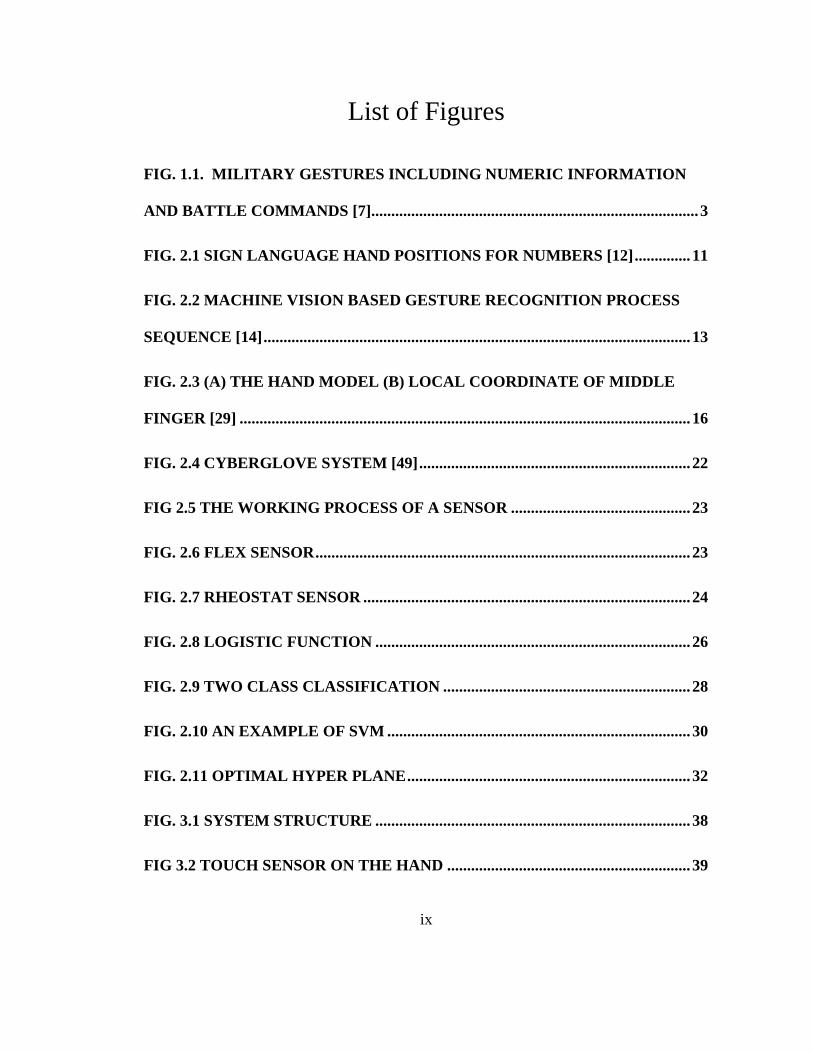
List of Figures
FIG. 1.1. MILITARY GESTURES INCLUDING NUMERIC INFORMATION
AND BATTLE COMMANDS [7].................................................................................. 3
FIG. 2.1 SIGN LANGUAGE HAND POSITIONS FOR NUMBERS [12] .............. 11
FIG. 2.2 MACHINE VISION BASED GESTURE RECOGNITION PROCESS
SEQUENCE [14] ........................................................................................................... 13
FIG. 2.3 (A) THE HAND MODEL (B) LOCAL COORDINATE OF MIDDLE
FINGER [29] ................................................................................................................. 16
FIG. 2.4 CYBERGLOVE SYSTEM [49] .................................................................... 22
FIG 2.5 THE WORKING PROCESS OF A SENSOR ............................................. 23
FIG. 2.6 FLEX SENSOR .............................................................................................. 23
FIG. 2.7 RHEOSTAT SENSOR .................................................................................. 24
FIG. 2.8 LOGISTIC FUNCTION ............................................................................... 26
FIG. 2.9 TWO CLASS CLASSIFICATION .............................................................. 28
FIG. 2.10 AN EXAMPLE OF SVM ............................................................................ 30
FIG. 2.11 OPTIMAL HYPER PLANE ....................................................................... 32
FIG. 3.1 SYSTEM STRUCTURE ............................................................................... 38
FIG 3.2 TOUCH SENSOR ON THE HAND ............................................................. 39

x
FIG 3.3 TOUCH COMMAND CIRCUIT .................................................................. 41
FIG. 3.4 FLEX SENSOR PROPERTIES ................................................................... 43
FIG. 3.5 FLEX SENSOR POSITION ......................................................................... 44
FIG. 3.6 FINGER FORMATION DETECTION CIRCUIT .................................... 45
FIG. 3.7 MOTION SENSOR POSITION ................................................................... 46
FIG. 3.8 YAW DRIFT IN 2 MINUTES WHILE THE SENSOR IS STABLE ....... 47
FIG. 3.9 DATA FUSION OF GYROSCOPE AND DIGITAL COMPASS ............ 48
FIG. 3.10 FINGER MODELING ................................................................................ 52
FIG. 3.11 HAND MODELING .................................................................................... 53
FIG. 3.12 NUMBER ONE IN ASL .............................................................................. 56
FIG. 4.1 THE FUNCTION OF PINS ON THE PEREGRINE GLOVE ................. 65
FIG 4.2 RE-SOLDERED CIRCUITS ON THE PEREGRINE GLOVE ................ 66
FIG. 4.3 FLEX SENSOR IMPLEMENTATION....................................................... 67
FIG. 4.4 CONNECTION OF MOTION SENSOR .................................................... 69
FIG. 4.5 ARDUINO MEGA ADK ............................................................................... 69
FIG. 4.6 ARDUINO NANO.......................................................................................... 69
FIG. 4.7 (A) WIRED VERSION SIGNAL ACQUISITION BOARD...................... 71
FIG. 4.7(B) WIRELESS VERSION SIGNAL ACQUISITION BOARD ................ 71
xi
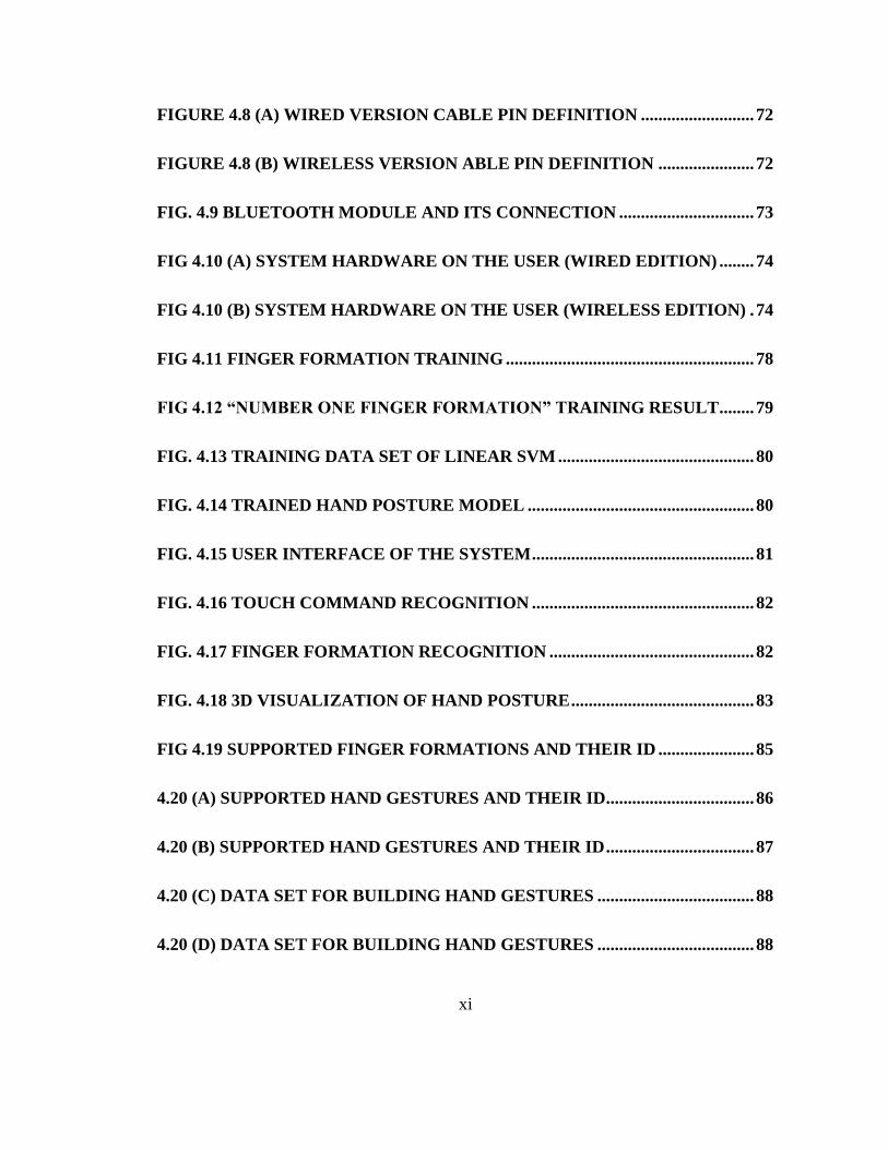
FIGURE 4.8 (A) WIRED VERSION CABLE PIN DEFINITION .......................... 72
FIGURE 4.8 (B) WIRELESS VERSION ABLE PIN DEFINITION ...................... 72
FIG. 4.9 BLUETOOTH MODULE AND ITS CONNECTION ............................... 73
FIG 4.10 (A) SYSTEM HARDWARE ON THE USER (WIRED EDITION) ........ 74
FIG 4.10 (B) SYSTEM HARDWARE ON THE USER (WIRELESS EDITION) . 74
FIG 4.11 FINGER FORMATION TRAINING ......................................................... 78
FIG 4.12 “NUMBER ONE FINGER FORMATION” TRAINING RESULT ........ 79
FIG. 4.13 TRAINING DATA SET OF LINEAR SVM ............................................. 80
FIG. 4.14 TRAINED HAND POSTURE MODEL .................................................... 80
FIG. 4.15 USER INTERFACE OF THE SYSTEM ................................................... 81
FIG. 4.16 TOUCH COMMAND RECOGNITION ................................................... 82
FIG. 4.17 FINGER FORMATION RECOGNITION ............................................... 82
FIG. 4.18 3D VISUALIZATION OF HAND POSTURE .......................................... 83
FIG 4.19 SUPPORTED FINGER FORMATIONS AND THEIR ID ...................... 85
4.20 (A) SUPPORTED HAND GESTURES AND THEIR ID .................................. 86
4.20 (B) SUPPORTED HAND GESTURES AND THEIR ID .................................. 87
4.20 (C) DATA SET FOR BUILDING HAND GESTURES .................................... 88
4.20 (D) DATA SET FOR BUILDING HAND GESTURES .................................... 88
xii
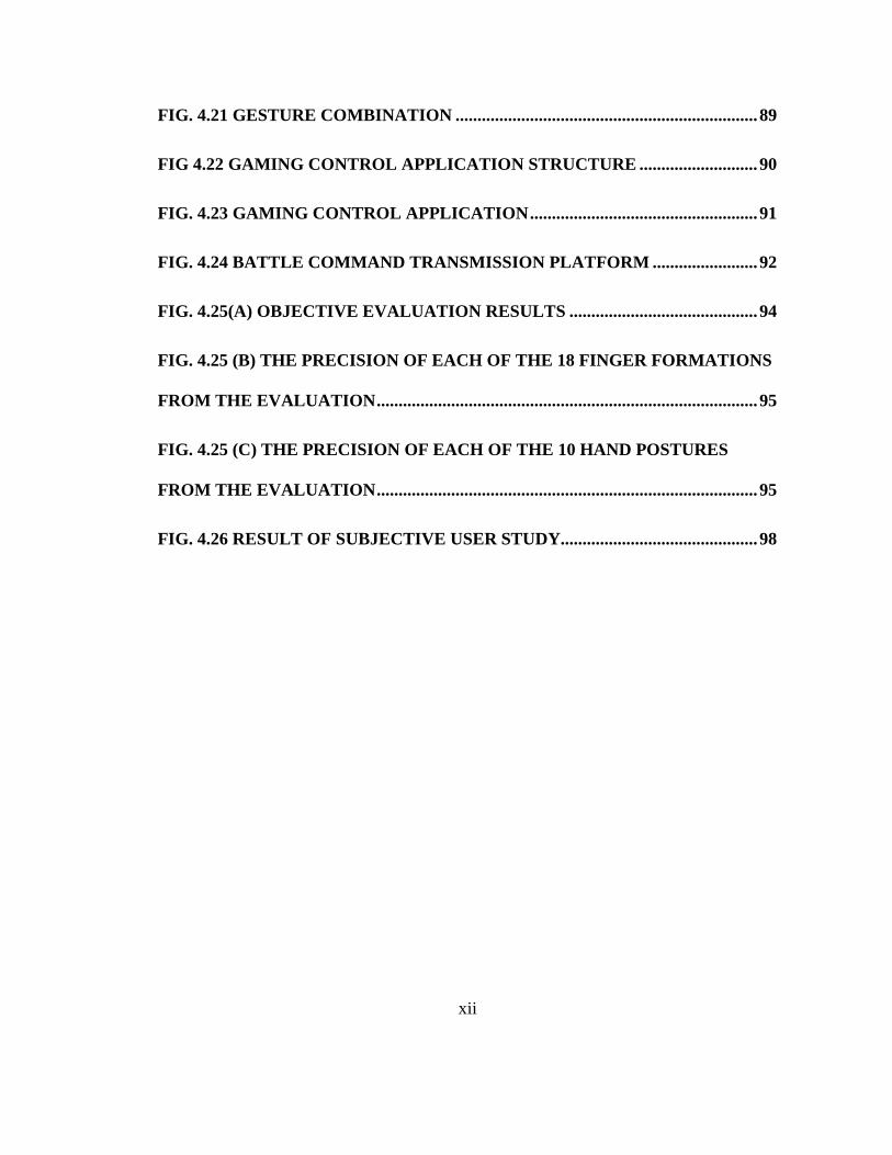
FIG. 4.21 GESTURE COMBINATION ..................................................................... 89
FIG 4.22 GAMING CONTROL APPLICATION STRUCTURE ........................... 90
FIG. 4.23 GAMING CONTROL APPLICATION .................................................... 91
FIG. 4.24 BATTLE COMMAND TRANSMISSION PLATFORM ........................ 92
FIG. 4.25(A) OBJECTIVE EVALUATION RESULTS ........................................... 94
FIG. 4.25 (B) THE PRECISION OF EACH OF THE 18 FINGER FORMATIONS
FROM THE EVALUATION ....................................................................................... 95
FIG. 4.25 (C) THE PRECISION OF EACH OF THE 10 HAND POSTURES
FROM THE EVALUATION ....................................................................................... 95
FIG. 4.26 RESULT OF SUBJECTIVE USER STUDY............................................. 98
xiii
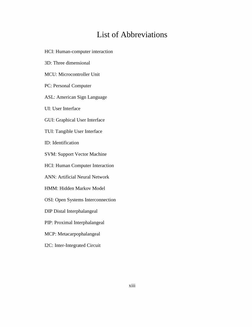
List of Abbreviations
HCI: Human-computer interaction
3D: Three dimensional
MCU: Microcontroller Unit
PC: Personal Computer
ASL: American Sign Language
UI: User Interface
GUI: Graphical User Interface
TUI: Tangible User Interface
ID: Identification
SVM: Support Vector Machine
HCI: Human Computer Interaction
ANN: Artificial Neural Network
HMM: Hidden Markov Model
OSI: Open Systems Interconnection
DIP Distal Interphalangeal
PIP: Proximal Interphalangeal
MCP: Metacarpophalangeal
I2C: Inter-Integrated Circuit
1
Chapter 1 Introduction
1.1 Background and Motivation
A “wearable device” refers to a portable device which can be worn directly on the
body or can be integrated into a user’s clothing or accessories. It is not only a hardware
device, but also a whole system which can achieve powerful functions with the support
of software, the exchange of data, and the interaction with a cloud server. Existing
wearable devices include those major classes: smart clothing, watch based, shoe based,
and glass based [1].
In 2012, Google announced an important research project: Google Project Glass [2],
which helps users expand reality by voice commanding a camera, video calling,

2
navigation, and surfing the Internet. Despite the fact that it is powerful for its advanced
diffraction display and numbers of applications, several arguments against aspects of
Project Glass are still challenging these kinds of devices because of the high cost of the
device, restriction in some public place by law for privacy purpose and so on. Watch
based wearable devices are already very popular in the market; besides smart watches
like Moto 360 [3], Samsung Gear [4] or Apple Watch [5] that possess their own
operating systems, a large number of fitness trackers that come in the form of
wristbands can also be classified in this category. Similar to wrist fitness trackers, shoe
based wearable devices usually are used for fitness tracking and health monitoring. The
discussion about wearable devices and the affiliated area: human-computer interaction
(HCI) have become an extremely popular topic both in academic and daily life. The
emergence of a large number of wearable devices [6] has significantly improved the
overall experience of the operation of computers or other smart devices, since these
devices have introduced multimodal interaction such as touch, voice, and motion
detection etc.
3
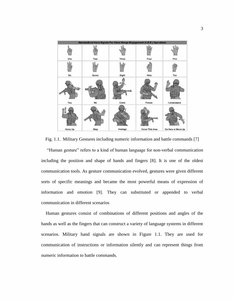
Fig. 1.1. Military Gestures including numeric information and battle commands [7]
“Human gesture” refers to a kind of human language for non-verbal communication
including the position and shape of hands and fingers [8]. It is one of the oldest
communication tools. As gesture communication evolved, gestures were given different
sorts of specific meanings and became the most powerful means of expression of
information and emotion [9]. They can substituted or appended to verbal
communication in different scenarios
Human gestures consist of combinations of different positions and angles of the
hands as well as the fingers that can construct a variety of language systems in different
scenarios. Military hand signals are shown in Figure 1.1. They are used for
communication of instructions or information silently and can represent things from
numeric information to battle commands.

4
Hand gesture recognition relates to several aspects of research including signal
processing, software engineering and sensor technology which significantly improves
the human-computer interaction. Currently, much research has been done in this area
and can be classified into two types: machine vision based and wearable device based.
The Machine Vision method, utilizing image processing by the computer to analyze
gestures, can be divided into two approaches [10]. The appearance based approaches
[10] use fingertip detection in order to construct the hand framework. Model based
approaches introduce a statistical pattern [10] to build the hand frame. Conversely,
sensor based methods typically use electronic, magnetic, ultrasonic, or optical sensors,
to collect data of physical displacements or rotations and recognize gestures by
processing the corresponding data. Among these approaches, the most popular devices
for gesture detection or hand movement detection are glove-based systems. Although
these methods already provide good quality for gesture recognition, there are still some
defects and room for improvement and we will discuss them in the next section.
Gesture recognition based HCI refers to an approach of HCI for better user
experience in some specific situations. At present, this method is being used in many
fields. Applications such as virtual reality, somatosensory games and so on. It provides
a natural way for interaction without traditional tools like keyboard, mouse or touch
screen.

5
1.2 Existing Problems
According to Morgan Stanley, wearable technology is a rapid growth business with a
potential of 1.6 trillion dollars market. Yet, over the past three decades, few of the
research projects pertaining to gesture recognition were evolved into products. Even
though there is a great need for such devices, still, there are some existing problems that
can be described as follows:
Limitation of Camera: The current machine vision approaches for detecting gestures
are able to reach an acceptable numbers of supported gestures. [] Nonetheless, cameras
or optical sensors are typically setup in a fixed location which directly affects their
portability. On the other hand, high precision recognition demands a high quality image
for analysis which can be affected by low light, mechanical vibration, noise, unhealthy
training model and so on; it also requires a direct line of sight between the sensor and
subject. Given these facts, we need to eliminate as many negative factors as possible to
make the system more portable and less susceptible to these issues.
Limitation of Supported Gestures: Most of the sensor based gesture recognition
systems either recognize the flexion degree of fingers or hand movement. Nonetheless,
human gestures consist of both finger and hand behaviors. This limits the existing
systems to only particular applications. This is because that these systems usually use
one kind of sensor. However, multiple kinds of sensors should be used for collection of
the signal. A more desirable system should support as many gestures as possible and the
supported type of gestures should be combined to match the original concept of hand
6
gestures, not carried out separately to adapt different requirement of different
applications as possible. Therefore, we should build the system with multiple types of
sensors to gather data with more degrees of freedom.
High Cost and Complex Setup: Both approaches engage complex and expensive
setups which will not be easily accepted by typical users. With the development of IC
technology, building a low cost hand gesture recognition system becomes possible, and
with a proper algorithm for processing data, we should be able to solve the complex
setup issue.
1.3 Objective and Contribution
The expending need for the wearable device with a natural way of interaction drives
the development of the multimodal interaction system. In this research work, we
developed a multimodal interaction wearable system for improving the human-
computer interaction experience by utilizing multiple kinds of sensors and building a
low-cost, portable data glove which support numerous gestures and which provides a
positive user experience.
The principle contributions of this research work can be summarized by the following
points:
Gesture recognition method: Design and development of a gesture recognition
method that combines multiple techniques including lookup table and support vector
machine (SVM), and offers better accuracy for distinguishing gestures in a wearable
7
device based gesture recognition system. This approach contributes to the increasing
demand for wearable devices used for the purpose of HCI.
The gesture recognition approaches that we have developed are as follows:
A mathematical model for defining gestures including position and rotation of hand,
flexion degree of fingers, as well as touch commands on the hand.
The introduction of lookup table method and SVM for processing data from sensors
and doing gesture recognition.
Multimodal interaction system: Design and development of a wearable data glove
system that consists of hardware and software design and implementation. The wearable
data glove collects hand gestures including finger formation, hand posture and touch
commands. We tried to settle the common problems of similar systems such as high
cost, limitations of supported gestures, and optimized user experience.
For the Multimode interaction system, the main contributions are:
Design of the multimodal data glove includes the setup of three kinds of sensors:
resistance rheostat sensors, flex sensors and a motion sensor, the design of circuit of
these sensors for signal acquisition.
The design and implantation of software function includes the organization,
transmission and process of data and the design of a new type of multimodal interaction
interface allows user to interact with computer though different kind of gestures.
1.4 Thesis Organization
The remainder of the thesis is organized as follows:
8
Chapter 2 presents the background and related works. We also compare the previous
research or products to our achievements in several aspects.
Chapter 3 proposes the idea of the multimodal data glove. It also extends to the
detailed design of the hardware of the system.
Chapter 4 explains the implementation of the system by introducing the hand gesture
recognition algorithm which cooperated with the hardware parts. The system result and
performance from evaluation will also be provided.
Chapter 5 summarizes the entire work, draws conclusions, and provides the potential
future work.
9
Chapter 2 Background and Related Work
Users and software developers have been constantly looking for the best way to
interact with computers. The design of the input device plays a significant role in
shaping the interaction experience. Wearable devices present a new and innovative
method to interact with computers. Interaction with hand gestures is considered as one
of the most natural methods. Hand gestures form a non-verbal communication language
consisting of the position and shape of a hand and fingers. In order to utilize this
method, many research contributions and commercial products have been proposed
over the years and can be classified into two categories: machine vision based and
wearable device based. The sensor based method for determining gestures uses an exact
signal from different sensors and processes the signal for detection. Machine vision

10
based approaches analyze images or videos to build a digital structure of the human
body, and to determine the gesture. In this chapter, we will provide a brief overview of
gestures, and introduce approaches to determine gestures for human-computer
interaction.
2.1 Human gesture and sign language
A gesture refers to the combination of positions and shape of a hand and fingers and
is a communication tool built by the speech center of our brain [8]. Gestures were given
different meanings in social practices and possess a high level of expressiveness and
they play the most important role in body language [11]. Sign language is a
combination of gestures and sometimes facial expressions typically used for inter-
human communication. It can express everything from simple numbers (see in figure
2.1) to complex sentences. It is often used in a variety of situations; for instance, deaf
individuals use sign language as an alternative to spoken language, soldiers use sign
language to transfer commands or information, and basketball referees communicate
through sign language to express various decisions. Generally speaking, sign language
can convert spoken language into an alternative visual form.
11
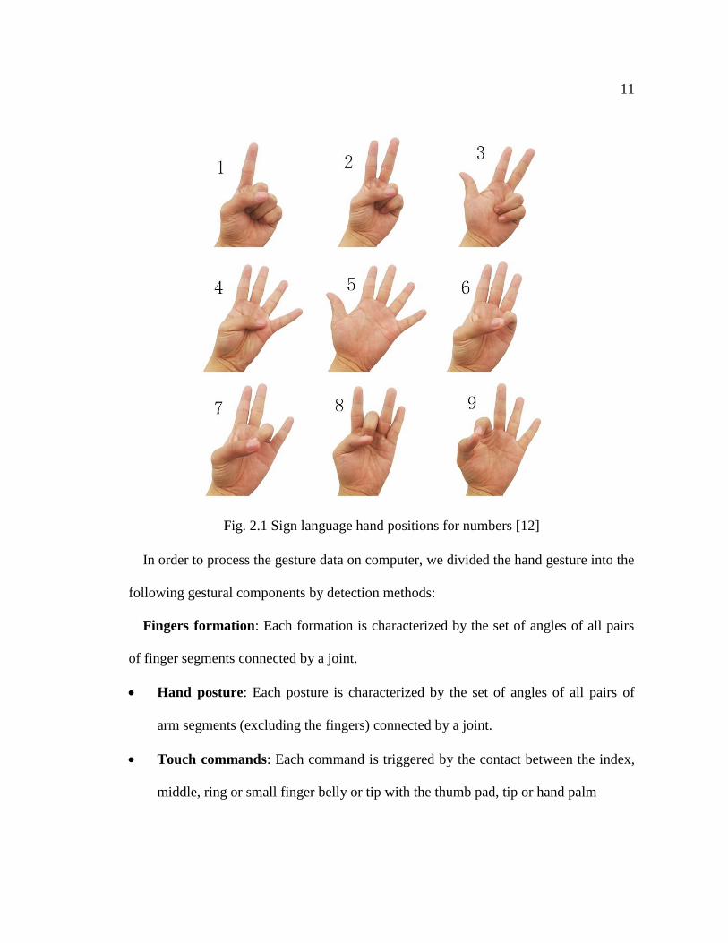
Fig. 2.1 Sign language hand positions for numbers [12]
In order to process the gesture data on computer, we divided the hand gesture into the
following gestural components by detection methods:
Fingers formation: Each formation is characterized by the set of angles of all pairs
of finger segments connected by a joint.
Hand posture: Each posture is characterized by the set of angles of all pairs of
arm segments (excluding the fingers) connected by a joint.
Touch commands: Each command is triggered by the contact between the index,
middle, ring or small finger belly or tip with the thumb pad, tip or hand palm
12
Compared to spoken language, gesture based communication methods or sign
languages are considered as natural ways for communication, and have the following
advantages:
They can be used in some environmental circumstances requiring silence, such as
Special Forces police operations since they do not need sound as the transmission
medium.
A single gesture can encode a wealth of information which can be per-established
following a particular protocol, and which provides more efficiency than the spoken
language.
Gesture communication methods and sign languages can be coded to allow only certain
people to understand the semantics of the communicated messages.
With these benefits, gesture communication methods and sign languages deliver a
platform for inter-human interaction and, as technology advances, they are being
expanded to improve human to computer interaction.
2.2 Gesture based HCI
Gesture based human-computer interaction refers to the use of hand gestures or sign
language to interact with a computer. The core technique for gesture based HCI is the
analysis or recognition of a gesture. Gesture communication methods or sign languages
use the combination of the finger formation and hand posture. Two main approaches
have been developed for acquiring and processing the various features of data required

13
to detect gestures: wearable device based and machine vision based [13]. We will
discuss these approaches in details.
Algorithms
Classified models
1
2
3
4
Applications
Modeled gestures
Camera
Cooperate
Sensor(Optional)
Fig. 2.2 Machine vision based gesture recognition process sequence [14]
The interaction based on gesture can be varied, and there are many applications on
the market such as virtual environment applications [15][16], gaming simulators [17],
3D modelling [18], robot controls [19], communication tools for deaf people [20][21],
mobile computer controls [22], medicine and rehabilitation [23][24] and so on.
2.2.1 Machine Vision based hand gesture HCI
Machine vision based gesture recognition methods are widely used in research works
and commercial endeavors [10]. A typical procedure for Machine vision based hand
14
gesture HCI is shown in figure 2.2. We will delve into the various stages of that
procedure in following sections.
2.2.1.1 Hand modeling [14]
Before gesture recognition, hand modeling should be performed. After hand
modeling, features are extracted from the video taken by the camera and compared to
the model previously built. By extracting and analyzing the features from the video, we
are able to establish a gesture model database for a natural user experience. Gesture
models have already been defined in other research fields such as linguistics and
anthropology. As we mentioned above, human gestures are constructed by the
combination of finger formation and hand posture; however, gestures should be first
divided by finger formation and hand angles and movement. The visual image is used to
determine these spatial modeling factors. Currently, the following are two of the most
popular approaches in modeling hand gestures:
Appearance-based methods: An appearance-based method analyzes the hand gesture
by matching predefined gestures. Both two dimensional image/video and 3D tracking
has been applied to this method. The main concerns in the analysis of factors for this
method are geometry and motion parameters and the position and angles of the
fingertips from the image/video. The method extracts the outlines of hands and fingers
and builds a matrix of the outline points to form an approximation of the outline using
interpolation nodes. Several works use fingertip recognition for building the hand
gesture model. The GREFIT system [25] is one of those which uses fingertip
15
recognition, deals with numerous hand postures, and contributes the following
approaches for building a fingertip model of the hand such as drawing a histogram for
colored marking of the fingertips and using multiple samples or images for the
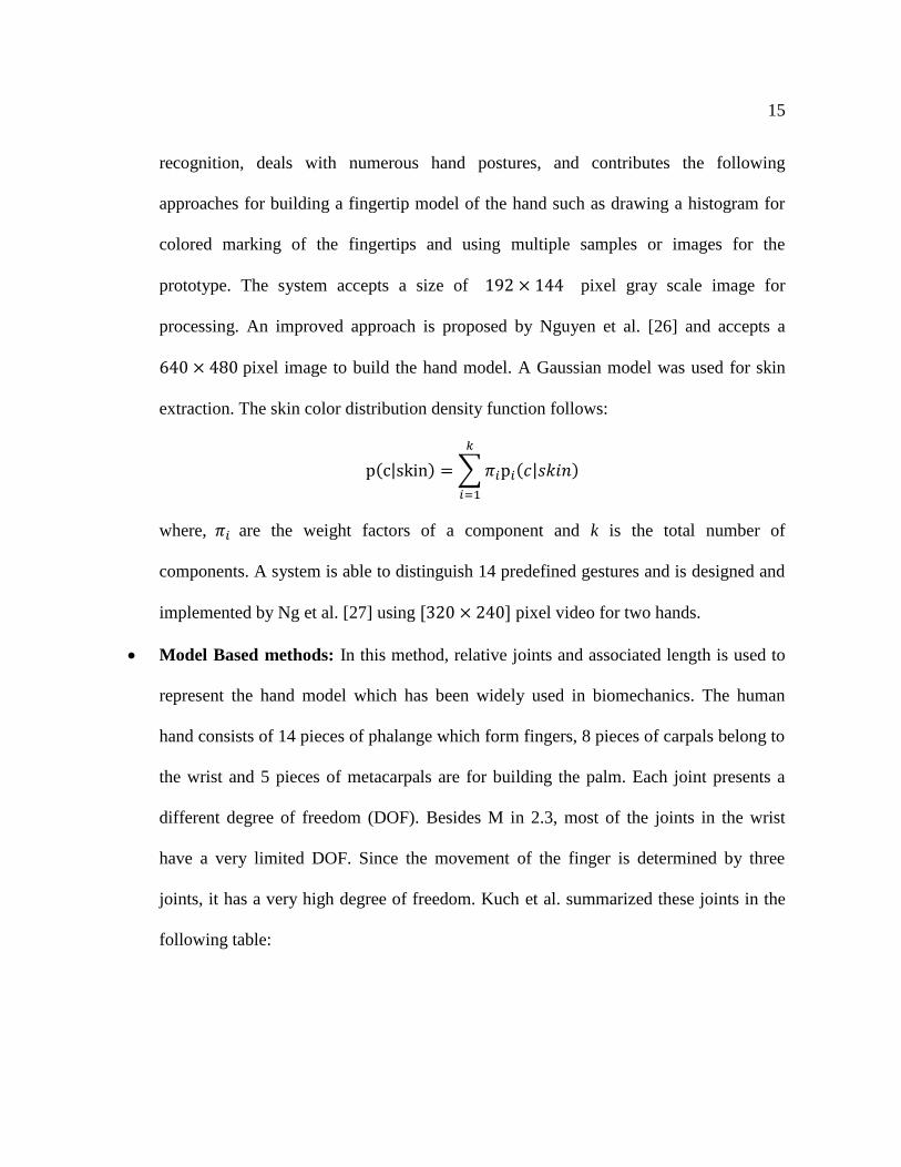
prototype. The system accepts a size of 192 × 144 pixel gray scale image for
processing. An improved approach is proposed by Nguyen et al. [26] and accepts a
640 × 480 pixel image to build the hand model. A Gaussian model was used for skin
extraction. The skin color distribution density function follows:
p(c|skin) = ∑ 𝜋𝑖p𝑖(𝑐|𝑠𝑘𝑖𝑛)
𝑘
𝑖=1
where, 𝜋𝑖 are the weight factors of a component and k is the total number of
components. A system is able to distinguish 14 predefined gestures and is designed and
implemented by Ng et al. [27] using [320 × 240] pixel video for two hands.
Model Based methods: In this method, relative joints and associated length is used to
represent the hand model which has been widely used in biomechanics. The human
hand consists of 14 pieces of phalange which form fingers, 8 pieces of carpals belong to
the wrist and 5 pieces of metacarpals are for building the palm. Each joint presents a
different degree of freedom (DOF). Besides M in 2.3, most of the joints in the wrist
have a very limited DOF. Since the movement of the finger is determined by three
joints, it has a very high degree of freedom. Kuch et al. summarized these joints in the
following table:
16
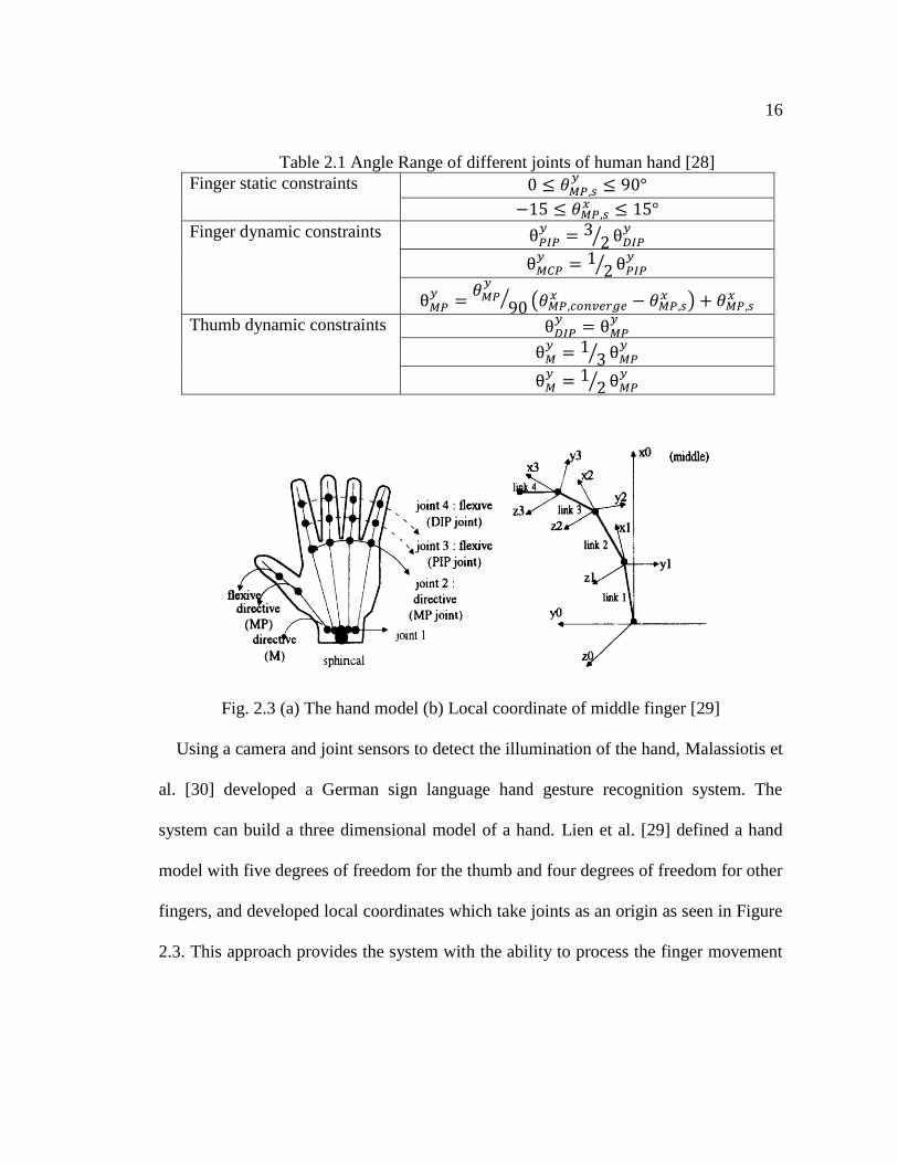
Table 2.1 Angle Range of different joints of human hand [28]
Finger static constraints 0 ≤ 𝜃𝑀𝑃,𝑠𝑦
≤ 90°
−15 ≤ 𝜃𝑀𝑃,𝑠𝑥 ≤ 15°
Finger dynamic constraints θ𝑃𝐼𝑃𝑦
= 32⁄ θ𝐷𝐼𝑃
𝑦
θ𝑀𝐶𝑃𝑦
= 12⁄ θ𝑃𝐼𝑃
𝑦
θ𝑀𝑃𝑦
=𝜃𝑀𝑃
𝑦
90⁄ (𝜃𝑀𝑃,𝑐𝑜𝑛𝑣𝑒𝑟𝑔𝑒
𝑥 − 𝜃𝑀𝑃,𝑠𝑥 ) + 𝜃𝑀𝑃,𝑠
𝑥
Thumb dynamic constraints θ𝐷𝐼𝑃𝑦
= θ𝑀𝑃𝑦
θ𝑀𝑦
= 13⁄ θ𝑀𝑃
𝑦
θ𝑀𝑦
= 12⁄ θ𝑀𝑃
𝑦
Fig. 2.3 (a) The hand model (b) Local coordinate of middle finger [29]
Using a camera and joint sensors to detect the illumination of the hand, Malassiotis et
al. [30] developed a German sign language hand gesture recognition system. The
system can build a three dimensional model of a hand. Lien et al. [29] defined a hand
model with five degrees of freedom for the thumb and four degrees of freedom for other
fingers, and developed local coordinates which take joints as an origin as seen in Figure
2.3. This approach provides the system with the ability to process the finger movement
17
in a linkage combination. Finally, they proposed a fast model-fitting method for
monitoring the movements of hand and fingers.
2.2.1.2 Hand gesture recognition
Hand gesture recognition in a computer vision based system analyzes models we
described in section 2.2.1.1. Usually, there should be a training process involving the
user before recognition. There exist several approaches aimed at recognizing different
gestures by the computer vision method:
Hidden Markov model: HMM is an extension of the Markov Model which describes
the Markov process with hidden parameters. It defines two stochastic processes: the
first process describes the probability relationship between outputs and states while the
second process describes the transitioning relationship between state and output, in
which the transition between states is hidden. It has been used for gesture recognition.
Generally, the 2D projection of a 3D hand model will be taken. Then a group of input
features will be provided. The temporal part of the gesture will be mapped by the HMM
classifier. The data will be applied for both training and testing the whole system.
Because of the particularity of HMM’s topology, the process of analyzing hand gestures
could be extremely complicated. It needs a large quantity of training samples and
recognition calculation results for a low speed of training and testing [31].
Finite-state Machine: Gestures are built into a series in an ordered spatiotemporal
model [32][33][34][35]. Different applications have different states. Therefore, gestures

18
will be treated as continuous spatiotemporal models collected by sensors, and are
represented as a set of points in sequence from two-dimensional space.
Soft Computing: Soft computing can produce low costs and robust processing. It
works in a similar way to the natural biochemical process in intelligent systems such as
human perception, brain structure, and immune processes, which deal with daily work
effectively. Genetic algorithms and artificial neural networks, along with other similar
algorithms can undertake the task of gesture recognition. Defects of this method is
obvious: the result is usually uncertain, imprecise and incomplete.
2.2.1.3 Applications
Computer vision based hand gesture HCI has a very wide range of applications. The
most common one is to replace the traditional input of a computer, such as keyboard,
mouse and joysticks [17]. Other applications, such as interpreters of sign language
[20][21], are also being widely developed. Furthermore, the field of applications in a
virtual environment is a huge branch which allows users to interact with virtual
environment by the movement of hand and fingers.
The most significant factor of gesture recognition is the correct rate of recognition.
The following table presents examples of research and their accuracy.
A lot of research works on machine vision based gesture HCI achieved very good
results [36][37][38]. However, a disadvantage of this method is very evident: the
requirement for a direct line of sight from camera to subject dictates that there will
always be a camera in front of the subject and nothing should block the light
19
propagation to the subject. Moreover, an inappropriate environment, such as a low light
setting, can significantly impact the results.
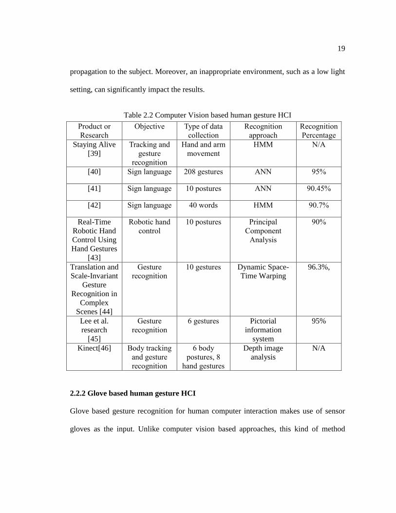
Table 2.2 Computer Vision based human gesture HCI
Product or
Research
Objective Type of data
collection
Recognition
approach
Recognition
Percentage
Staying Alive
[39]
Tracking and
gesture
recognition
Hand and arm
movement
HMM N/A
[40] Sign language 208 gestures ANN 95%
[41] Sign language 10 postures ANN 90.45%
[42] Sign language 40 words HMM 90.7%
Real-Time
Robotic Hand
Control Using
Hand Gestures
[43]
Robotic hand
control
10 postures Principal
Component
Analysis
90%
Translation and
Scale-Invariant
Gesture
Recognition in
Complex
Scenes [44]
Gesture
recognition
10 gestures Dynamic Space-
Time Warping
96.3%,
Lee et al.
research
[45]
Gesture
recognition
6 gestures Pictorial
information
system
95%
Kinect[46] Body tracking
and gesture
recognition
6 body
postures, 8
hand gestures
Depth image
analysis
N/A
2.2.2 Glove based human gesture HCI
Glove based gesture recognition for human computer interaction makes use of sensor
gloves as the input. Unlike computer vision based approaches, this kind of method
20
collects physical displacement and rotation of fingers and/or hands by sensors. Glove
based gesture HCI has been developed for more than 30 years. Several typical examples,
such as 5DT Data Glove Ultra [47], VMG 30 [48], CyberGlove [49] led advances in
this approach. Dipietro et al. [50] summarized applications of glove based systems as
follows:
Applications in information and visualization which help to improve user experience
when they are interacting with data
An input device for design and manufacturing which typically was an input in a virtual
environment
Applications in robot programming which provide a natural and easy way for
manipulating robots
Applications which help an artist or game developer in tracing the animation of a
human body, corroborated with other tracking techniques
Applications which understand sign language by gesture recognition and can be used
for both human to human interaction and human computer interaction.
Since, in this research, our focus is gesture recognition, we consider the following
products or research in Table 2.3:
21
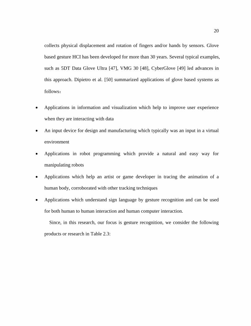
Table 2.3 Glove based human gesture HCI systems
Product or
research
Objective Type of data
collection
Sensor(s) Price
CyberGlove
III [49]
Motion capture and
graphic animations
Finger formation Flex sensors Very
high
ShapeHand
[51]
hand motion
capture
Finger formation Flexible ribbon
sensors
Very
high
5DT Data
Glove 5 Ultra
[47]
Motion capture and
animation
professionals
Finger formation
Hand posture
Flex sensors
Motion sensors
~ $900
DG5 Glove
3.0 [52]
Motion detection Finger formation,
hand posture
Flex sensors,
motion sensor
~ $600
Peregrine
[17]
Gaming device to
replace keyboard
Touch commands Resistor
sensors
~ $150
MYO
[53]
Computer and
mobile device
control
5 finger formations,
wrist rotation
EMG sensor,
motion sensor
$199
The peregrine Glove provides over 30 kinds of touch command but the lack of
detection of finger formation and hand posture limits its application. MYO is a good
product to interact with smart appliance and simple computer control since they just
support 5 gestures. The peregrine glove and MYO are all in an acceptable price.
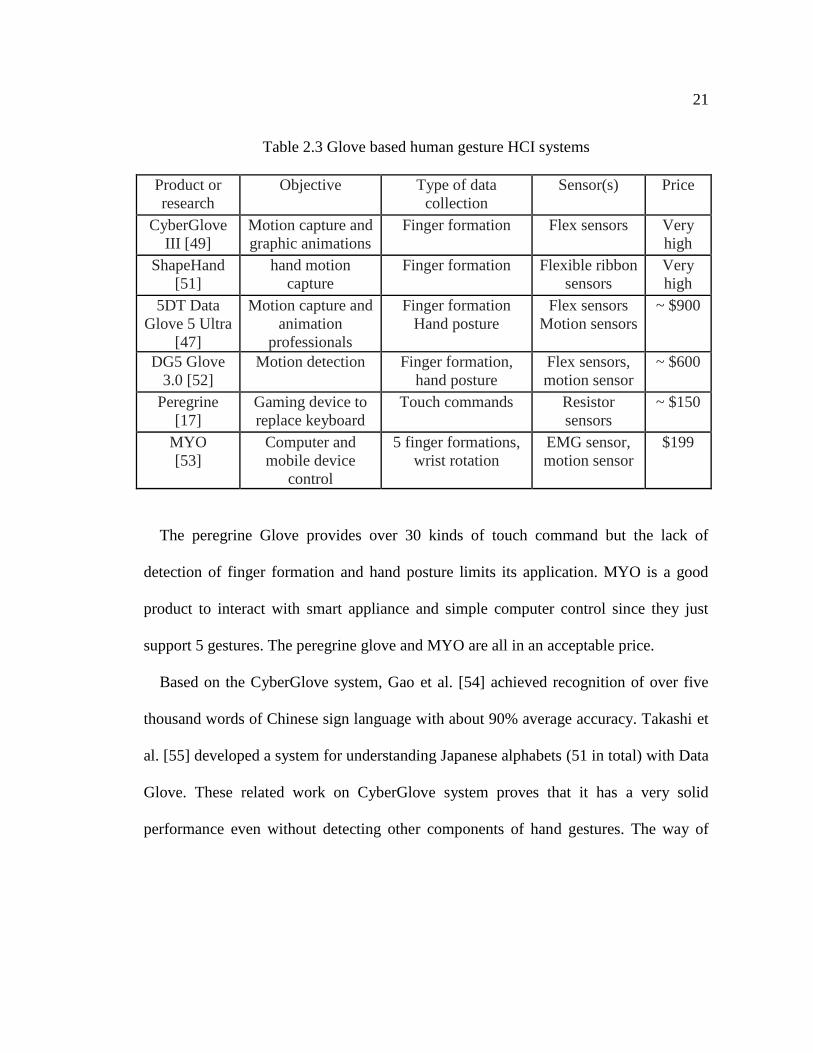
Based on the CyberGlove system, Gao et al. [54] achieved recognition of over five
thousand words of Chinese sign language with about 90% average accuracy. Takashi et
al. [55] developed a system for understanding Japanese alphabets (51 in total) with Data
Glove. These related work on CyberGlove system proves that it has a very solid
performance even without detecting other components of hand gestures. The way of
22
CyberGlove system to measure the hand posture is either use an outer skeleton or
machine vision method which significantly limits the mobile use of this system.
Fig. 2.4 CyberGlove System [49]
5DT Data Glove 5 Ultra and DG5 Glove 3.0 all provide finger movement and hand
orientation detection which could support a large number of gestures but none of them
provides an approachable price since if we want to recognize gestures as many as
possible, multiple kinds of sensors will be applied and that will increase the price of
system exponentially. More importantly, no product or research combines all three
components of hand gesture we talked before: finger formation, hand posture and touch
command which will provides more supported gestures then other existing ones. Given
these studies, we can conclude that the more gestures these systems are able to
recognize, the higher the cost will be for the system.
23
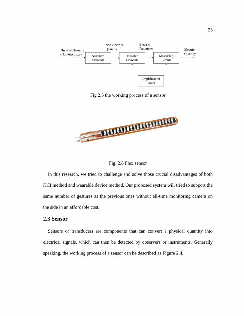
Fig 2.5 the working process of a sensor
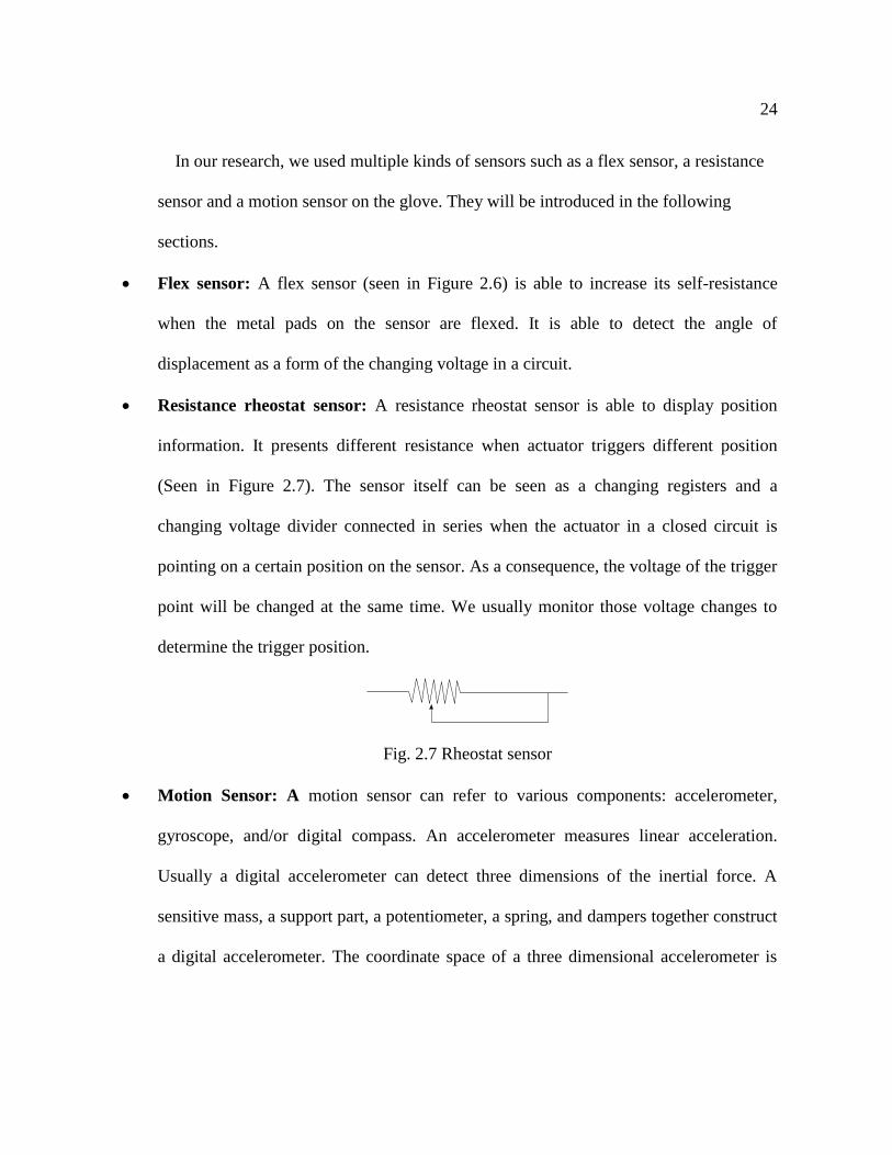
Fig. 2.6 Flex sensor
In this research, we tried to challenge and solve those crucial disadvantages of both
HCI method and wearable device method. Our proposed system will tried to support the
same number of gestures as the previous ones without all-time monitoring camera on
the side in an affordable cost.
2.3 Sensor
Sensors or transducers are components that can convert a physical quantity into
electrical signals, which can then be detected by observers or instruments. Generally
speaking, the working process of a sensor can be described as Figure 2.4.
Sensitive
Elements
Transfer
Elements
Measuring
Circuit
Amplification
Power
Physical Quantity
(Non-electrical)
Non-electrical
Quantity
Electric
Parameter Electric
Quantity
24
In our research, we used multiple kinds of sensors such as a flex sensor, a resistance
sensor and a motion sensor on the glove. They will be introduced in the following
sections.
Flex sensor: A flex sensor (seen in Figure 2.6) is able to increase its self-resistance
when the metal pads on the sensor are flexed. It is able to detect the angle of
displacement as a form of the changing voltage in a circuit.
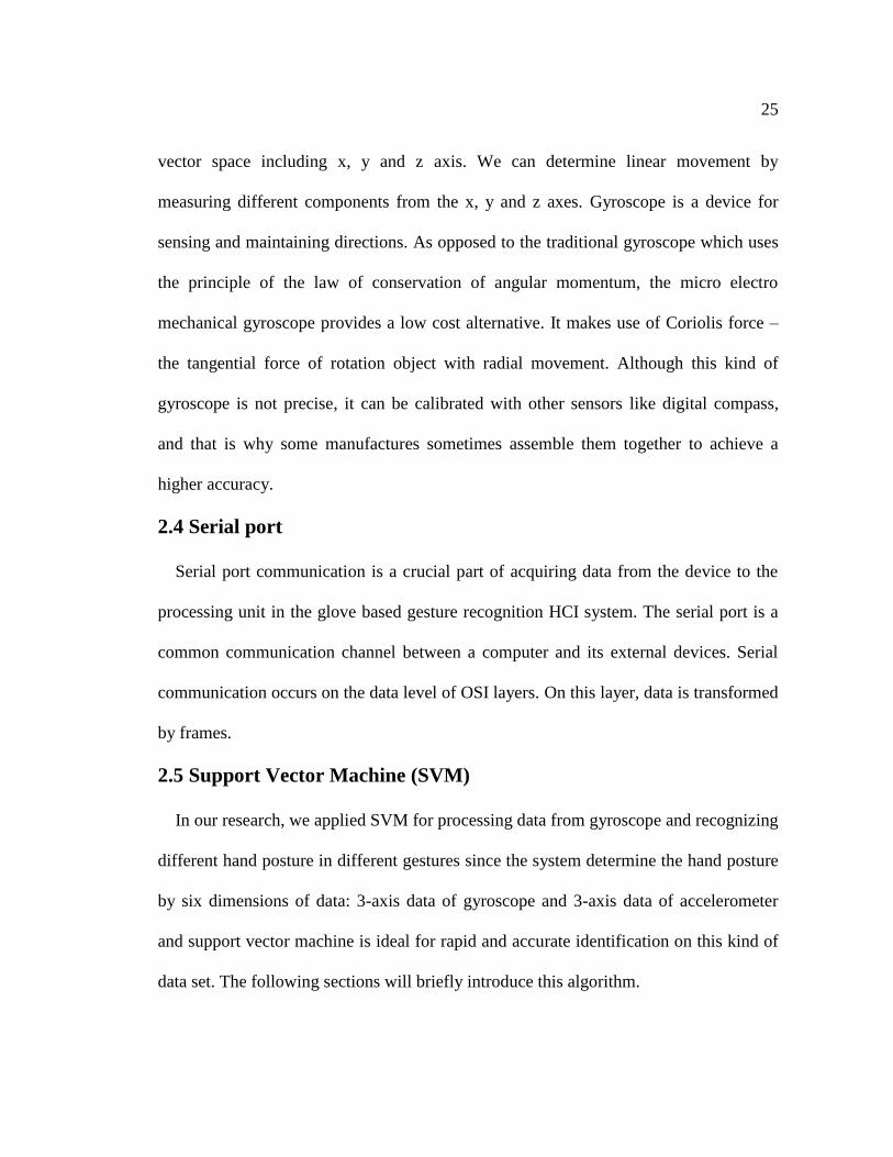
Resistance rheostat sensor: A resistance rheostat sensor is able to display position
information. It presents different resistance when actuator triggers different position
(Seen in Figure 2.7). The sensor itself can be seen as a changing registers and a
changing voltage divider connected in series when the actuator in a closed circuit is
pointing on a certain position on the sensor. As a consequence, the voltage of the trigger
point will be changed at the same time. We usually monitor those voltage changes to
determine the trigger position.
Fig. 2.7 Rheostat sensor
Motion Sensor: A motion sensor can refer to various components: accelerometer,
gyroscope, and/or digital compass. An accelerometer measures linear acceleration.
Usually a digital accelerometer can detect three dimensions of the inertial force. A
sensitive mass, a support part, a potentiometer, a spring, and dampers together construct
a digital accelerometer. The coordinate space of a three dimensional accelerometer is
25
vector space including x, y and z axis. We can determine linear movement by
measuring different components from the x, y and z axes. Gyroscope is a device for
sensing and maintaining directions. As opposed to the traditional gyroscope which uses
the principle of the law of conservation of angular momentum, the micro electro
mechanical gyroscope provides a low cost alternative. It makes use of Coriolis force –
the tangential force of rotation object with radial movement. Although this kind of
gyroscope is not precise, it can be calibrated with other sensors like digital compass,
and that is why some manufactures sometimes assemble them together to achieve a
higher accuracy.
2.4 Serial port
Serial port communication is a crucial part of acquiring data from the device to the
processing unit in the glove based gesture recognition HCI system. The serial port is a
common communication channel between a computer and its external devices. Serial
communication occurs on the data level of OSI layers. On this layer, data is transformed
by frames.
2.5 Support Vector Machine (SVM)
In our research, we applied SVM for processing data from gyroscope and recognizing
different hand posture in different gestures since the system determine the hand posture
by six dimensions of data: 3-axis data of gyroscope and 3-axis data of accelerometer
and support vector machine is ideal for rapid and accurate identification on this kind of
data set. The following sections will briefly introduce this algorithm.
26
SVM is a two-class classifier model. The basic definition of the model is a linear
classifier for maximize the margin between different classes. The training strategy of
SVM is to maximize the margin between classes and convert it into convex quadratic
programming. [56]
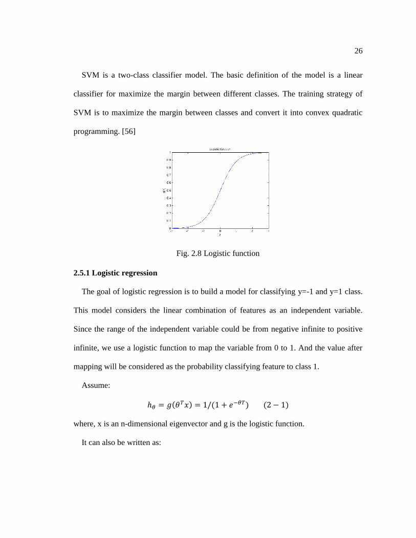
Fig. 2.8 Logistic function
2.5.1 Logistic regression
The goal of logistic regression is to build a model for classifying y=-1 and y=1 class.
This model considers the linear combination of features as an independent variable.
Since the range of the independent variable could be from negative infinite to positive
infinite, we use a logistic function to map the variable from 0 to 1. And the value after
mapping will be considered as the probability classifying feature to class 1.
Assume:
ℎ𝜃 = 𝑔(𝜃𝑇𝑥) = 1/(1 + 𝑒−𝜃𝑇) (2 − 1)
where, x is an n-dimensional eigenvector and g is the logistic function.
It can also be written as:
27
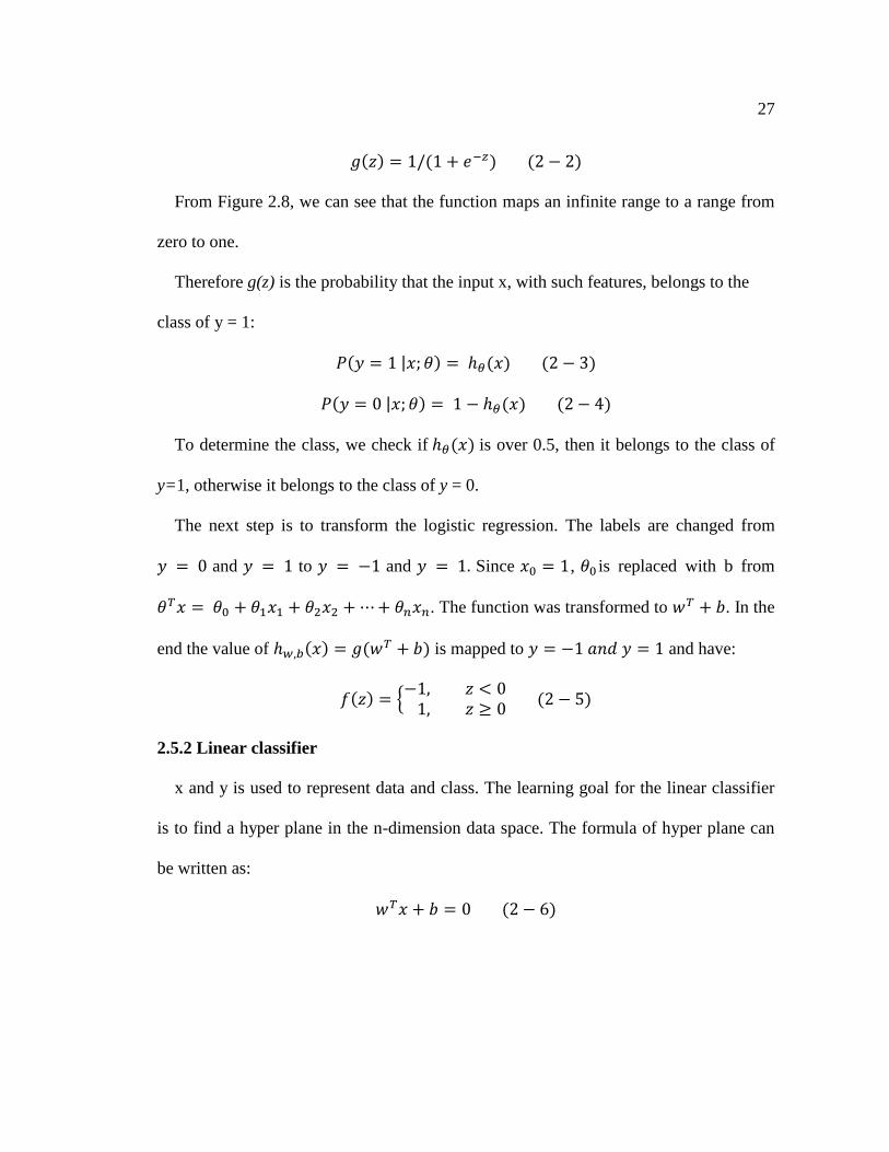
𝑔(𝑧) = 1/(1 + 𝑒−𝑧) (2 − 2)
From Figure 2.8, we can see that the function maps an infinite range to a range from
zero to one.
Therefore g(z) is the probability that the input x, with such features, belongs to the
class of y = 1:
𝑃(𝑦 = 1 |𝑥; 𝜃) = ℎ𝜃(𝑥) (2 − 3)
𝑃(𝑦 = 0 |𝑥; 𝜃) = 1 − ℎ𝜃(𝑥) (2 − 4)
To determine the class, we check if ℎ𝜃(𝑥) is over 0.5, then it belongs to the class of
y=1, otherwise it belongs to the class of y = 0.
The next step is to transform the logistic regression. The labels are changed from
𝑦 = 0 and 𝑦 = 1 to 𝑦 = −1 and 𝑦 = 1. Since 𝑥0 = 1, 𝜃0 is replaced with b from
𝜃𝑇𝑥 = 𝜃0 + 𝜃1𝑥1 + 𝜃2𝑥2 + ⋯ + 𝜃𝑛𝑥𝑛. The function was transformed to 𝑤𝑇 + 𝑏. In the
end the value of ℎ𝑤,𝑏(𝑥) = 𝑔(𝑤𝑇 + 𝑏) is mapped to 𝑦 = −1 𝑎𝑛𝑑 𝑦 = 1 and have:
𝑓(𝑧) = {−1, 𝑧 < 0
1, 𝑧 ≥ 0 (2 − 5)
2.5.2 Linear classifier
x and y is used to represent data and class. The learning goal for the linear classifier
is to find a hyper plane in the n-dimension data space. The formula of hyper plane can
be written as:
𝑤𝑇𝑥 + 𝑏 = 0 (2 − 6)
28
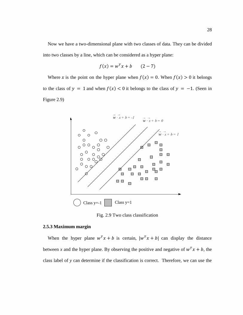
Now we have a two-dimensional plane with two classes of data. They can be divided
into two classes by a line, which can be considered as a hyper plane:
𝑓(𝑥) = 𝑤𝑇𝑥 + 𝑏 (2 − 7)
Where 𝑥 is the point on the hyper plane when 𝑓(𝑥) = 0. When 𝑓(𝑥) > 0 it belongs
to the class of 𝑦 = 1 and when 𝑓(𝑥) < 0 it belongs to the class of 𝑦 = −1. (Seen in
Figure 2.9)
Fig. 2.9 Two class classification
2.5.3 Maximum margin
When the hyper plane 𝑤𝑇𝑥 + 𝑏 is certain, |𝑤𝑇𝑥 + 𝑏| can display the distance
between x and the hyper plane. By observing the positive and negative of 𝑤𝑇𝑥 + 𝑏, the
class label of y can determine if the classification is correct. Therefore, we can use the
Class y=-1 Class y=1
w · x + b = 0→ →w · x + b = -1
→ →
w · x + b = 1→ →
29
positive or negative sign of 𝑦(𝑤𝑇𝑥 + 𝑏) to determine if the classification is correct.
Here we define a functional margin as:
𝛾 = 𝑦(𝑤𝑇𝑥 + 𝑏) = 𝑦𝑓(𝑥) (2 − 8)
The problem of this definition is that when w or b change, the margin will change at
the same time. So we need to add constraint conditions for the normal vector w.
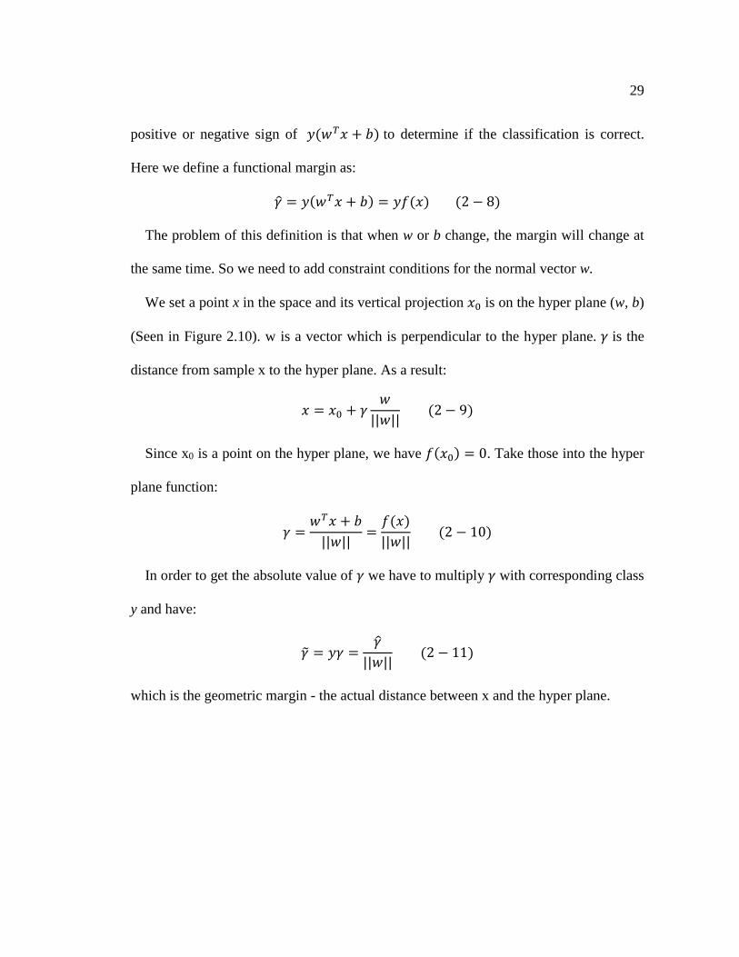
We set a point x in the space and its vertical projection 𝑥0 is on the hyper plane (w, b)
(Seen in Figure 2.10). w is a vector which is perpendicular to the hyper plane. 𝛾 is the
distance from sample x to the hyper plane. As a result:
𝑥 = 𝑥0 + 𝛾𝑤
||𝑤|| (2 − 9)
Since x0 is a point on the hyper plane, we have 𝑓(𝑥0) = 0. Take those into the hyper
plane function:
𝛾 =𝑤𝑇𝑥 + 𝑏
||𝑤||=
𝑓(𝑥)
||𝑤|| (2 − 10)
In order to get the absolute value of 𝛾 we have to multiply 𝛾 with corresponding class
y and have:
�̃� = 𝑦𝛾 =𝛾
||𝑤|| (2 − 11)
which is the geometric margin - the actual distance between x and the hyper plane.
30
Fig. 2.10 An example of SVM
When we are classifying data, the larger the gap between the hyper plane and a set of
data, the larger is the confidence. In order to get as high a confidence as we can, the
selected hyper plane should be able to maximize the gap. Therefore, the objective
function of the maximum margin classifier would be:
𝑚𝑎𝑥�̃� (2 − 12)
subject to
𝑦𝑖(𝑤𝑇𝑥𝑖 + 𝑏) = 𝛾𝑖 ≥ 𝛾 (𝑖 = 1,2, … , 𝑛) (2 − 13)
let 𝛾 = 1 , we have �̃� =1
||𝑤||, s.t. 𝑦𝑖(𝑤𝑇𝑥 + 𝑏) ≥ 1 (𝑖 = 1,2, … , 𝑛) and the former
formula can be transformed into:
Class y=-1 Class y=1
w · x + b = 0→ →w · x + b = -1
→ →
w · x + b = 1→ →
x
x0
w

31
𝑚𝑎𝑥1
||𝑤|| (2 − 14)
subject to
𝑦𝑖(𝑤𝑇𝑥 + 𝑏) ≥ 1 (𝑖 = 1,2, … , 𝑛) (2 − 15)
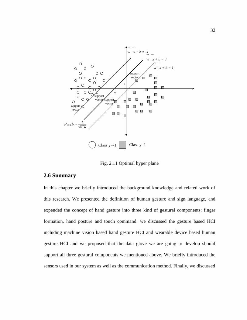
Referring to Figure 2.11, the bold line in the middle is the optimal hyper plane. The
distance between the optimal hyper plane and the other two planes is equal. Those
points on the sidelines are support vectors. This only considers the linearly separable
situation, which is sufficient for our research. As for the other case, it will not be
discussed in this paper.
Sometimes, there will be some noise in the gap between classes. We apply a soft
margin to choose the hyper plane to avoid most of these noise data. The slack variable
𝜉𝑖 determines the misclassification degree for the training sets. We change the objective
function into another form: 𝑚𝑖𝑛 1
2||𝑤||2. Considering the slack variable, we have:
min (1
2||𝑤||2 + 𝐶 ∑ 𝜉𝑖
𝑛
𝑖=1
) (2 − 16)
subject to
𝑦𝑖(𝑤𝑇𝑥 + 𝑏) ≥ 1 − 𝜉𝑖 (𝑖 = 1,2, … , 𝑛) 𝑎𝑛𝑑 𝜉𝑖 ≥ 0 (2 − 17)
32
Fig. 2.11 Optimal hyper plane
2.6 Summary
In this chapter we briefly introduced the background knowledge and related work of
this research. We presented the definition of human gesture and sign language, and
expended the concept of hand gesture into three kind of gestural components: finger
formation, hand posture and touch command. we discussed the gesture based HCI
including machine vision based hand gesture HCI and wearable device based human
gesture HCI and we proposed that the data glove we are going to develop should
support all three gestural components we mentioned above. We briefly introduced the
sensors used in our system as well as the communication method. Finally, we discussed
Class y=-1 Class y=1
w · x + b = 0
→ →w · x + b = -1
→ →
w · x + b = 1
→ →
support
vector
support
vector
support
vector
support
vector
b
w
33
the techniques that we will integrate into our gesture detection algorithm: linear support
vector machine and lookup table.
34
Chapter 3 Proposed Multimodal Data Glove System
3.1 System Objective
As we mentioned in the existing problem of gesture-based human computer
interaction, there are several drawbacks to the current approaches [9][57][50]. Therefore,
the system we propose here should solve these problems in order to improve the human
computer interaction. Specifically, we propose the following:
The system should be able to recognize more gestures: From the related works,
we know that computer vision-based gesture recognition supports a fair number of
gestures For example, the Peregrine Glove support at least 30 kind of touch
commands [17]. However, as we concluded in section 2.2.2, glove-based
approaches tend to limit the supported gestures when it comes to a low cost

35
solutions. Also, the type of supported gestures is limited. The glove based system
we propose, should support as many gestures as possible. There is no research
simultaneously support fingers formation, hand posture and touch commands.
Low cost and ease of use: Most glove-based systems with multiple-type inputs
require a large hardware expense, which limits the promotion of this type of
solution. The system we propose should control the cost of hardware to be as low
as possible. Meanwhile, the system we propose should be able to use in multiple
purposes for a majority of users and the supported gestures in the system provided
should be either common gestures or easy to remember.
3.2 System Overview
The data glove system we propose here is a glove-based system that allows a user to
interact with a computing device. It supports all of the gestural components we
described in section 2.1 including:
Finger formation
Hand posture
Touch command
Some or all of the above mentioned gestural components can be combined to
generate distinct gestures. Thus, the system we propose will offer a large quantity of
gestures.
In order to detect hand gestures, a glove-based sensor system is proposed. We utilize
a group of sensors to detect various gestural components. We use positional rheostat
36
sensors to detect the contact between fingers and thumb or palm, flex sensors to
determine the fingers’ formation, and a motion sensor to monitor the hand posture. We
also built an embedded system comprised of electric circuits and a microcontroller to
collect the sensor analog signals, convert them to digital and relay them to a computing
device. In order to recognize gestural information, we proposed a new hand gesture
model which simplifies the former model [17] [47] [48] [49] for lower cost on sensors
and fast response on recognition; the model will be introduced in section 3.4.2. We
applied two proven methods: lookup table and linear SVM to develop three algorithms
for recognition of different gestural components: lookup table based touch command
and finger formation recognition algorithm and linear SVM based hand posture
recognition algorithm. They will be discussed in section 3.4.3. We achieved a
replacement solution for a keyboard and mouse by using the gesture recognition of the
proposed system to manipulate characters in video games. We also improved the user
experience in controlling a map application. Potential applications such as battle
command transmission platform has also been proposed. The applications will be
discussed in chapter 4.
The various system modules are shown in Figure 3.1. In our proposed system,
gestural information is collected by the signal acquisition layer, made up of the system’s
sensors, as well their necessary circuitry. A microcontroller-based system will convert
the analog signal into digital form so that the computer is able to process this data; it
also acts as a data communication platform to connect the sensor with the upper
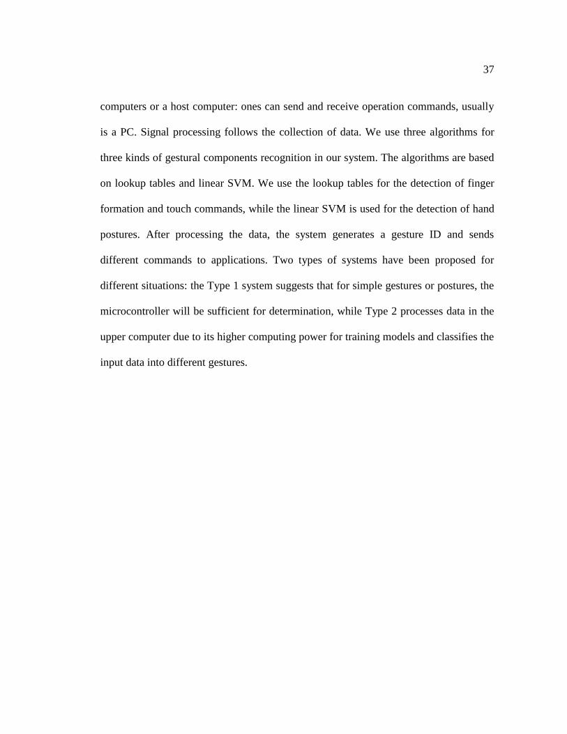
37
computers or a host computer: ones can send and receive operation commands, usually
is a PC. Signal processing follows the collection of data. We use three algorithms for
three kinds of gestural components recognition in our system. The algorithms are based
on lookup tables and linear SVM. We use the lookup tables for the detection of finger
formation and touch commands, while the linear SVM is used for the detection of hand
postures. After processing the data, the system generates a gesture ID and sends
different commands to applications. Two types of systems have been proposed for
different situations: the Type 1 system suggests that for simple gestures or postures, the
microcontroller will be sufficient for determination, while Type 2 processes data in the
upper computer due to its higher computing power for training models and classifies the
input data into different gestures.
38
Signal Acquisition
Signal Processing
Command Processing
Applications
Sensor Signal (Analog)
Sensor Signal (Digital)
Gesture Data
Command
Type
1
Type
2
Gesture Model
Database
Command
Database
Fig. 3.1 System Structure
3.3 Signal Acquisition
The signal acquisition component of the proposed data glove is in charge of detecting
and measuring the movement and rotation of the hand and fingers as well as the touch
commands stimulated by the fingers. We employed three kinds of sensors to collect the
necessary information for gesture detection:
39
A Resistance rheostat sensor
A flex sensor
A multiple dimensional motion sensor
Corresponding circuits for each kind of sensor were also designed, built, and
connected to a microcontroller system.
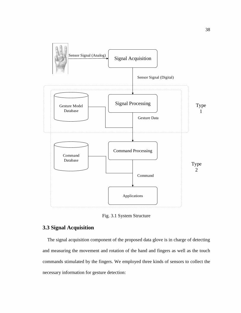
Fig 3.2 Touch sensor on the hand
3.3.1 Resistance Rheostat
The rheostat sensor we used is made of stainless steel with a high electric resistance.
The self-resistance is changed by the different activing position. After doing
background research, we discovered that a product called the Peregrine Glove with
similar functions already existed [17]. In our research, we used their product as our base
40
glove. We redesigned and built the detection circuit and only used their embedded
sensors on the glove. The position of sensors is shown in Figure 3.2: rheostat sensors
are placed on one side of little finer, ring finger, middle finger and index finger. Three
activator are placed on thumb pad, tip and palm. User need to use one of these activator
to touch a certain position on the sensor to issue a command.
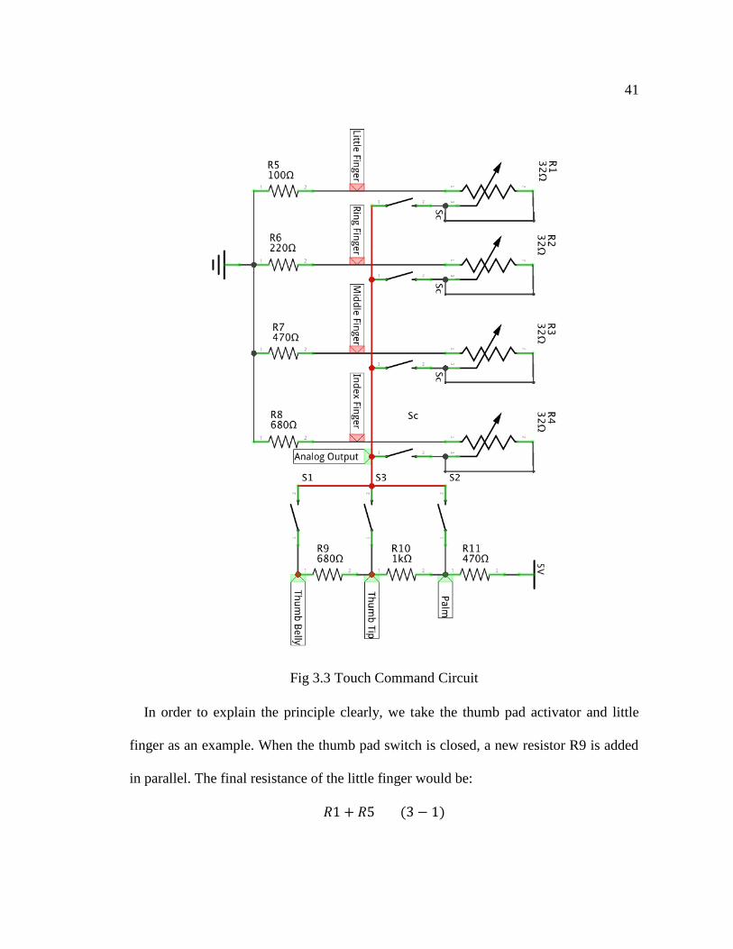
Figure 3.3 shows the circuit for touch command detection. R1, R2, R3 and R4 are the
rheostat sensors implemented on the little finger, ring finger middle finger and index
finger of the user’s hand, respectively. These sensors are connected in parallel. We can
also notice that R5, R6, R7, R8 are fixed resistors that have been connected in series
with each rheostat sensor on each finger. In order to build step values of on different
fingers, we set those fixed resistors to have different resistances. The switch in the
figure is to represent the case when an activator touches the sensor, when it will build a
new closed loop. Switch Sc is closed depending on which finger was touched. The
output of this circuit is the measurement of voltage at the analog output point.
41
Fig 3.3 Touch Command Circuit
In order to explain the principle clearly, we take the thumb pad activator and little
finger as an example. When the thumb pad switch is closed, a new resistor R9 is added
in parallel. The final resistance of the little finger would be:
𝑅1 + 𝑅5 (3 − 1)
42
where the value of R1 will be determined by the position on the sensor. For the closed
circuit, the resistance would be:
𝑅1 + 𝑅5 + 𝑅9 + 𝑅10 + 𝑅11 (3 − 2)
The voltage of the little finger label point on the little finger would be:
𝑉𝐼𝑁𝑅1
𝑅1 + 𝑅5 + 𝑅9 + 𝑅10 + 𝑅11 (3 − 3)
In this case,
5𝑅1
𝑅1 + 100 + 680 + 1000 + 470=
5𝑅1
𝑅1 + 2250 (3 − 4)
Therefore, the changing values of R1 determine the touch position on the hand and
impact the voltage of the Analog Output point. By measuring the output analog voltage
signals, we are able to detect the touch command of different positions on different
fingers.
3.3.2 Flex Sensor
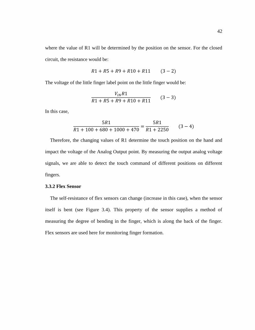
The self-resistance of flex sensors can change (increase in this case), when the sensor
itself is bent (see Figure 3.4). This property of the sensor supplies a method of
measuring the degree of bending in the finger, which is along the back of the finger.
Flex sensors are used here for monitoring finger formation.
43
Fig. 3.4 Flex sensor properties
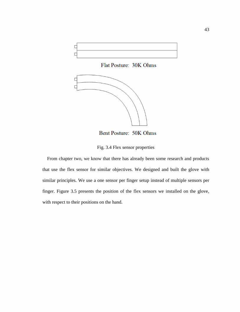
From chapter two, we know that there has already been some research and products
that use the flex sensor for similar objectives. We designed and built the glove with
similar principles. We use a one sensor per finger setup instead of multiple sensors per
finger. Figure 3.5 presents the position of the flex sensors we installed on the glove,
with respect to their positions on the hand.
44
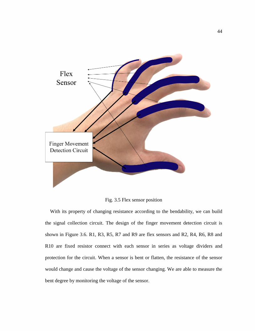
Fig. 3.5 Flex sensor position
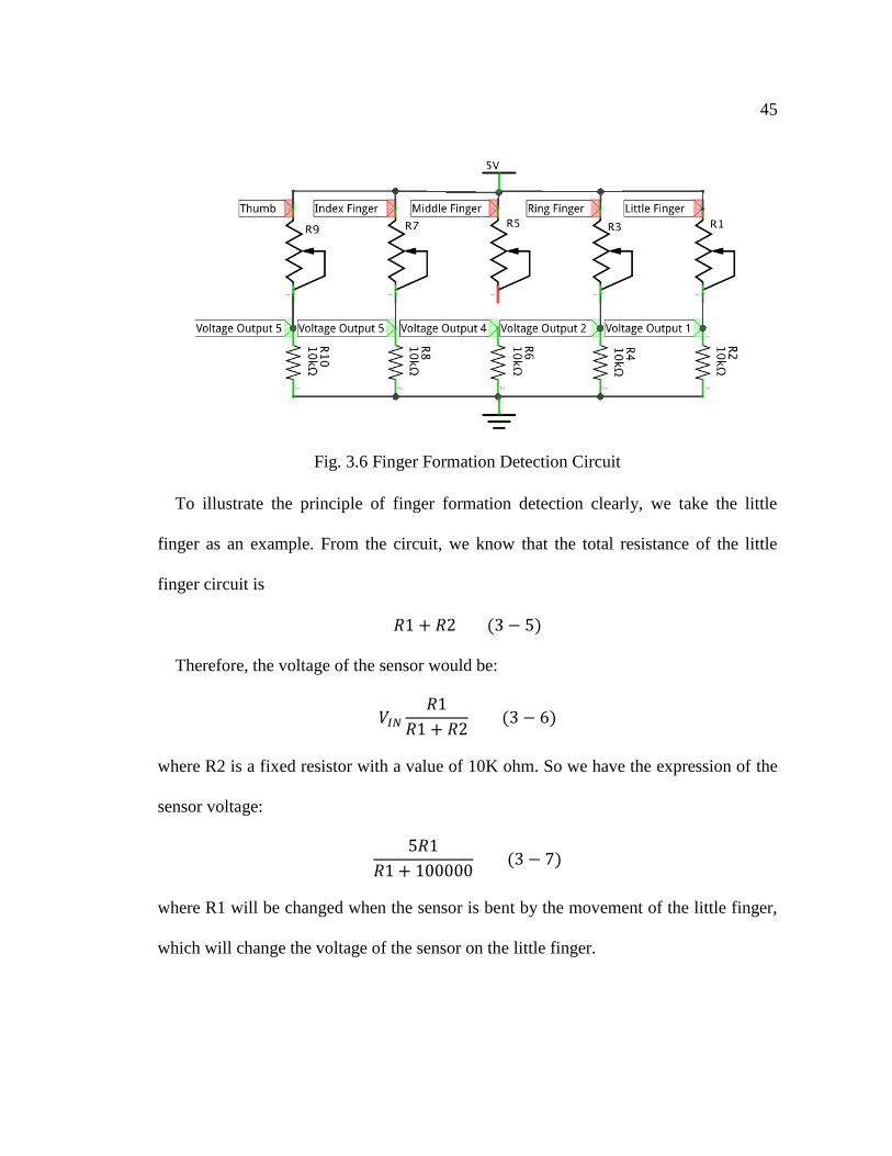
With its property of changing resistance according to the bendability, we can build
the signal collection circuit. The design of the finger movement detection circuit is
shown in Figure 3.6. R1, R3, R5, R7 and R9 are flex sensors and R2, R4, R6, R8 and
R10 are fixed resistor connect with each sensor in series as voltage dividers and
protection for the circuit. When a sensor is bent or flatten, the resistance of the sensor
would change and cause the voltage of the sensor changing. We are able to measure the
bent degree by monitoring the voltage of the sensor.
45
Fig. 3.6 Finger Formation Detection Circuit
To illustrate the principle of finger formation detection clearly, we take the little
finger as an example. From the circuit, we know that the total resistance of the little
finger circuit is
𝑅1 + 𝑅2 (3 − 5)
Therefore, the voltage of the sensor would be:
𝑉𝐼𝑁
𝑅1
𝑅1 + 𝑅2 (3 − 6)
where R2 is a fixed resistor with a value of 10K ohm. So we have the expression of the
sensor voltage:
5𝑅1
𝑅1 + 100000 (3 − 7)
where R1 will be changed when the sensor is bent by the movement of the little finger,
which will change the voltage of the sensor on the little finger.
46
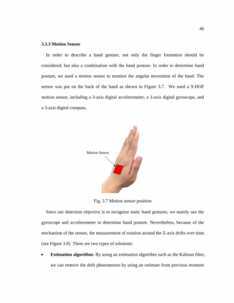
3.3.3 Motion Sensor
In order to describe a hand gesture, not only the finger formation should be
considered, but also a combination with the hand posture. In order to determine hand
posture, we used a motion sensor to monitor the angular movement of the hand. The
sensor was put on the back of the hand as shown in Figure 3.7. We used a 9-DOF
motion sensor, including a 3-axis digital accelerometer, a 3-axis digital gyroscope, and
a 3-axis digital compass.
Fig. 3.7 Motion sensor position
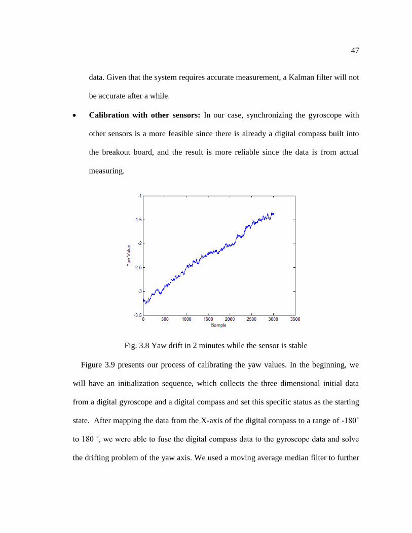
Since our detection objective is to recognize static hand gestures, we mainly use the
gyroscope and accelerometer to determine hand posture. Nevertheless, because of the
mechanism of the sensor, the measurement of rotation around the Z-axis drifts over time.
(see Figure 3.8) There are two types of solutions:
Estimation algorithm: By using an estimation algorithm such as the Kalman filter,
we can remove the drift phenomenon by using an estimate from previous moment
Motion Sensor
47
data. Given that the system requires accurate measurement, a Kalman filter will not
be accurate after a while.
Calibration with other sensors: In our case, synchronizing the gyroscope with
other sensors is a more feasible since there is already a digital compass built into
the breakout board, and the result is more reliable since the data is from actual
measuring.
Fig. 3.8 Yaw drift in 2 minutes while the sensor is stable
Figure 3.9 presents our process of calibrating the yaw values. In the beginning, we
will have an initialization sequence, which collects the three dimensional initial data
from a digital gyroscope and a digital compass and set this specific status as the starting
state. After mapping the data from the X-axis of the digital compass to a range of -180˚
to 180 ˚, we were able to fuse the digital compass data to the gyroscope data and solve
the drifting problem of the yaw axis. We used a moving average median filter to further
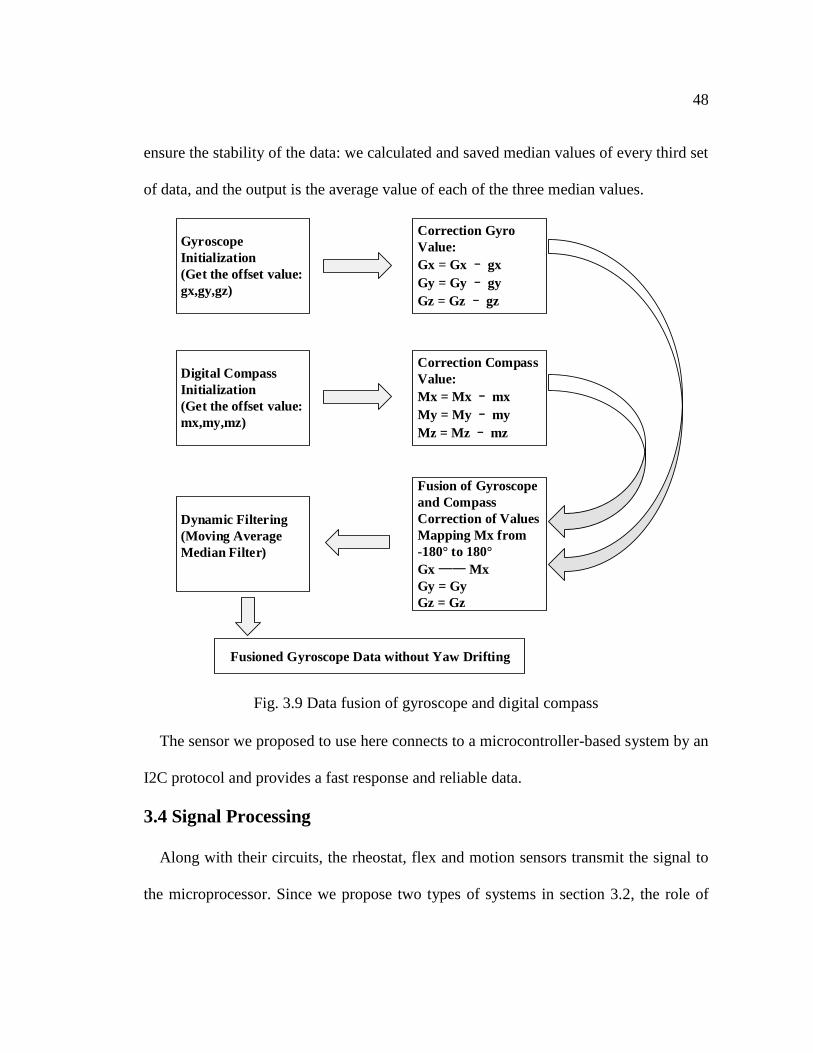
48
ensure the stability of the data: we calculated and saved median values of every third set
of data, and the output is the average value of each of the three median values.
Gyroscope
Initialization
(Get the offset value:
gx,gy,gz)
Digital Compass
Initialization
(Get the offset value:
mx,my,mz)
Correction Gyro
Value:
Gx = Gx – gx
Gy = Gy – gy
Gz = Gz – gz
Correction Compass
Value:
Mx = Mx – mx
My = My – my
Mz = Mz – mz
Fusion of Gyroscope
and Compass
Correction of Values
Mapping Mx from
-180° to 180°
Gx —— Mx
Gy = Gy
Gz = Gz
Dynamic Filtering
(Moving Average
Median Filter)
Fusioned Gyroscope Data without Yaw Drifting
Fig. 3.9 Data fusion of gyroscope and digital compass
The sensor we proposed to use here connects to a microcontroller-based system by an
I2C protocol and provides a fast response and reliable data.
3.4 Signal Processing
Along with their circuits, the rheostat, flex and motion sensors transmit the signal to
the microprocessor. Since we propose two types of systems in section 3.2, the role of

49
the microcontroller is different for each type. In Type 1 systems, the microcontroller
first converts the analog signal into digital forms in order to process it. The
microcontroller recognizes the gesture and sends its ID directly to the client. For the
Type 2 systems, the microcontroller acts as a hub. After converting the analog signal
into its digital equivalent, the microcontroller transmits the signal directly to a
connected computing device where the gesture recognition process is executed.
3.4.1 Signal Conversion and Pre-processing
Signal conversion and pre-processing is done by the microcontroller system for both
types of systems. Signals from different kinds of sensors require different methods of
pre-processing:
Rheostat sensor: Readings from the rheostat sensors on the fingers present
different voltages at different touch positions actuated by different activator. We
need to map those signals with different magnitudes to pre-defined values in order
to make it easier for management and identification.
Flex sensor: We use individual ports to monitor the flex sensors on each finger.
However, despite having the same degree of bend, two flex sensors may display
different resistances. Besides, the degree of bend in the flex sensors would be
different on different fingers. Therefore, we need to unify this data by using
remapping:
𝑋 =(𝑥−𝑥𝑙)(𝑈−𝐿)
𝑥𝑢−𝑥𝑙+ 𝑈 (3 − 8)

50
where X is the remapped data, x is the initial data, xl is the lower limit of the initial
data, xu is the upper limit of the initial data. U is the upper limit of the remapped
data, and L is the lower limit of the remapped data. In our case, we remap the data
into 10 levels: from 0 to 9.
Motion sensor: Data from the motion sensor is transmitted by an Inter-Integrated
Circuit protocol in the form of a complete data set including gyroscope,
accelerometer and digital compass data. After the process of fusion of the
gyroscope data with the digital compass as mentioned above, the microcontroller
only needs to organize and send the calibrated data to the upper computer.
Finally, the microcontroller packs all of the above into a package. We set up head and
end verification to secure the transmission. We also included the length of the package
which makes it easier for the upper computer to analyze. An example of a completed
package of data would be:
AA 44 0C 01 02 03 04 05 06 07 08 09 0A 0B 0C EA
where AA 44 is the format header of the package. 0C is the length of the contents,
which is 12 bytes in this case. The data before EA is the data we sent, which includes 3
bytes of data from the accelerometer, and 3 bytes of fusion gyroscope data; 5 bytes of
data of the flex sensors is the contents of the package in hexadecimal. In the end, EA is
the carriage return.
51
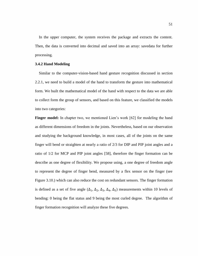
In the upper computer, the system receives the package and extracts the content.
Then, the data is converted into decimal and saved into an array: savedata for further
processing.
3.4.2 Hand Modeling
Similar to the computer-vision-based hand gesture recognition discussed in section
2.2.1, we need to build a model of the hand to transform the gesture into mathematical
form. We built the mathematical model of the hand with respect to the data we are able
to collect form the group of sensors, and based on this feature, we classified the models
into two categories:
Finger model: In chapter two, we mentioned Lien’s work [62] for modeling the hand
as different dimensions of freedom in the joints. Nevertheless, based on our observation
and studying the background knowledge, in most cases, all of the joints on the same
finger will bend or straighten at nearly a ratio of 2/3 for DIP and PIP joint angles and a
ratio of 1/2 for MCP and PIP joint angles [58], therefore the finger formation can be
describe as one degree of flexibility. We propose using, a one degree of freedom angle
to represent the degree of finger bend, measured by a flex sensor on the finger (see
Figure 3.10.) which can also reduce the cost on redundant sensors. The finger formation
is defined as a set of five angle (∆1, ∆2, ∆3, ∆4, ∆5) measurements within 10 levels of
bending: 0 being the flat status and 9 being the most curled degree. The algorithm of
finger formation recognition will analyze these five degrees.
52
Fig. 3.10 Finger modeling
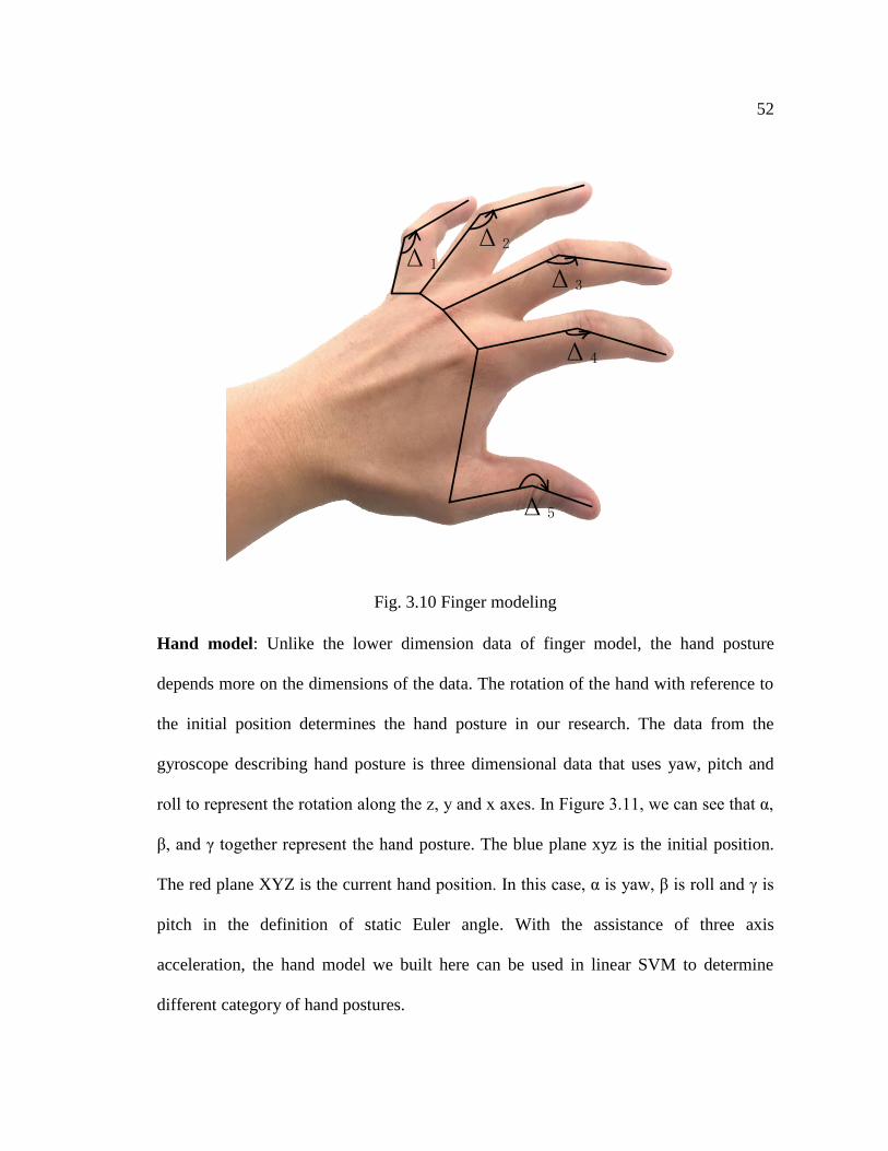
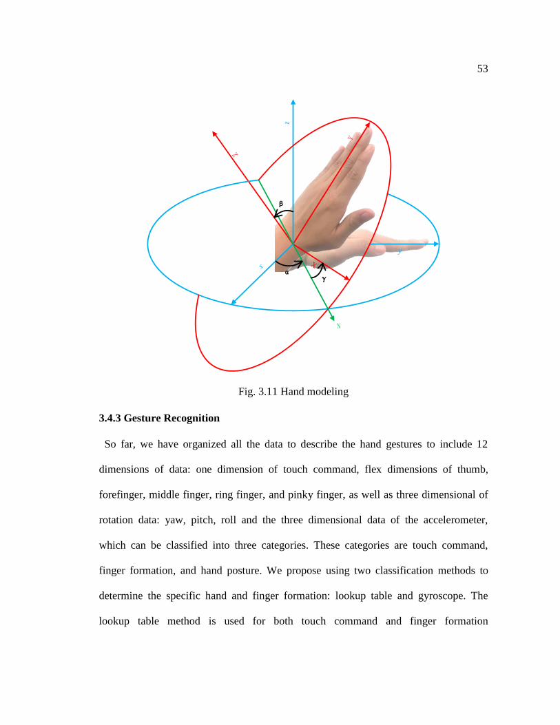
Hand model: Unlike the lower dimension data of finger model, the hand posture
depends more on the dimensions of the data. The rotation of the hand with reference to
the initial position determines the hand posture in our research. The data from the
gyroscope describing hand posture is three dimensional data that uses yaw, pitch and
roll to represent the rotation along the z, y and x axes. In Figure 3.11, we can see that α,
β, and γ together represent the hand posture. The blue plane xyz is the initial position.
The red plane XYZ is the current hand position. In this case, α is yaw, β is roll and γ is
pitch in the definition of static Euler angle. With the assistance of three axis
acceleration, the hand model we built here can be used in linear SVM to determine
different category of hand postures.
Δ1
Δ2
Δ3
Δ4
Δ5
53
Fig. 3.11 Hand modeling
3.4.3 Gesture Recognition
So far, we have organized all the data to describe the hand gestures to include 12
dimensions of data: one dimension of touch command, flex dimensions of thumb,
forefinger, middle finger, ring finger, and pinky finger, as well as three dimensional of
rotation data: yaw, pitch, roll and the three dimensional data of the accelerometer,
which can be classified into three categories. These categories are touch command,
finger formation, and hand posture. We propose using two classification methods to
determine the specific hand and finger formation: lookup table and gyroscope. The
lookup table method is used for both touch command and finger formation
z
y
β
αγ
54
determination, while the linear support vector machine is used to determine the hand
posture component.
3.4.3.1 Lookup Table
We use a lookup table to determine the touch command and finger formation because
the parameters for the postures of both can be predefined and they are not complex to
process. The touch command and finger formations are tagged as a touch command ID
or a finger formation ID from the result of the lookup table, while their parameters are
combined into a number to search for the corresponding gesture ID. We introduce both
categories below:
Touch command: In order to recognize the touch command on the glove, we first
test readings from each position with different actuators and record this data. We then
build a lookup table with the resulting gesture IDs and corresponding readings. For
precision of the system, we repeated the test three times for each reading. The
recognition of touch commands for both Type 1 and Type 2 systems is determined by
the Algorithm 1.
From touch command recognition algorithm, we can see that the system constantly
collects the touch command data from the received data package, and tries to find the
reading within the touch command database to get the touch ID. The system then
displays the touch position and actuator and/or sends the corresponding command to
applications.
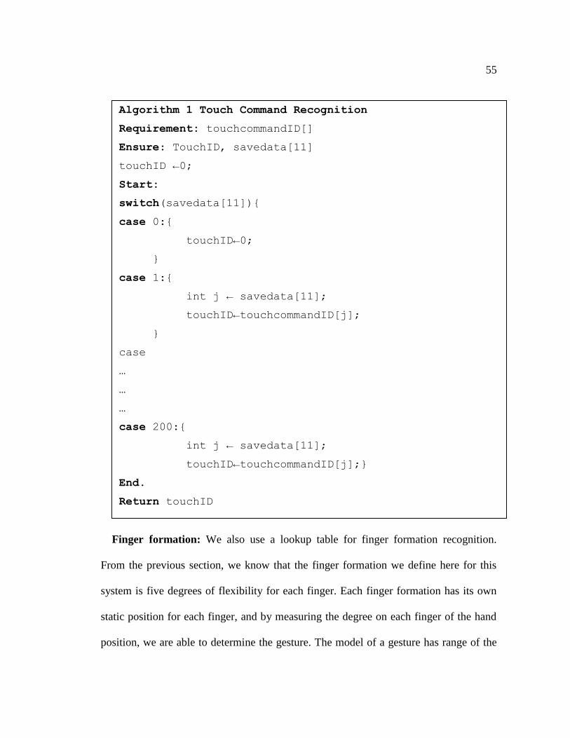
55
Finger formation: We also use a lookup table for finger formation recognition.
From the previous section, we know that the finger formation we define here for this
system is five degrees of flexibility for each finger. Each finger formation has its own
static position for each finger, and by measuring the degree on each finger of the hand
position, we are able to determine the gesture. The model of a gesture has range of the
Algorithm 1 Touch Command Recognition
Requirement: touchcommandID[]
Ensure: TouchID, savedata[11]
touchID ←0;
Start:
switch(savedata[11]){
case 0:{
touchID←0;
}
case 1:{
int j ← savedata[11];
touchID←touchcommandID[j];
}
case
…
…
…
case 200:{
int j ← savedata[11];
touchID←touchcommandID[j];}
End.
Return touchID
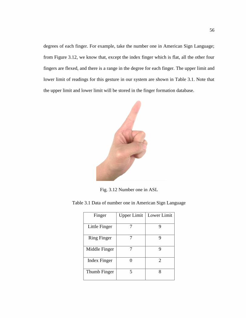
56
degrees of each finger. For example, take the number one in American Sign Language;
from Figure 3.12, we know that, except the index finger which is flat, all the other four
fingers are flexed, and there is a range in the degree for each finger. The upper limit and
lower limit of readings for this gesture in our system are shown in Table 3.1. Note that
the upper limit and lower limit will be stored in the finger formation database.
Fig. 3.12 Number one in ASL
Table 3.1 Data of number one in American Sign Language
Finger Upper Limit Lower Limit
Little Finger 7 9
Ring Finger 7 9
Middle Finger 7 9
Index Finger 0 2
Thumb Finger 5 8
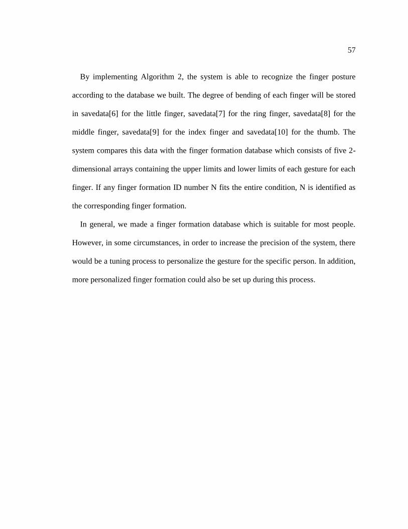
57
By implementing Algorithm 2, the system is able to recognize the finger posture
according to the database we built. The degree of bending of each finger will be stored
in savedata[6] for the little finger, savedata[7] for the ring finger, savedata[8] for the
middle finger, savedata[9] for the index finger and savedata[10] for the thumb. The
system compares this data with the finger formation database which consists of five 2-
dimensional arrays containing the upper limits and lower limits of each gesture for each
finger. If any finger formation ID number N fits the entire condition, N is identified as
the corresponding finger formation.
In general, we made a finger formation database which is suitable for most people.
However, in some circumstances, in order to increase the precision of the system, there
would be a tuning process to personalize the gesture for the specific person. In addition,
more personalized finger formation could also be set up during this process.
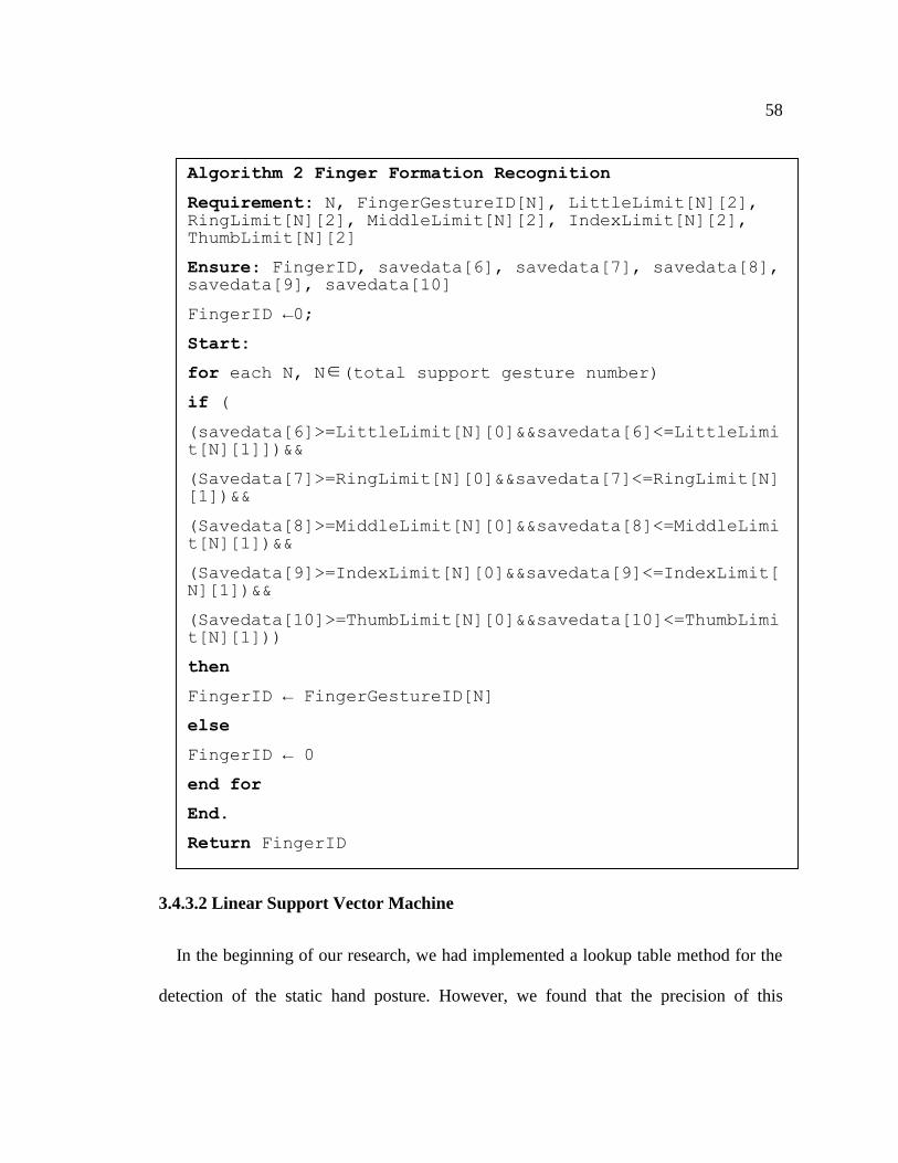
58
3.4.3.2 Linear Support Vector Machine
In the beginning of our research, we had implemented a lookup table method for the
detection of the static hand posture. However, we found that the precision of this
Algorithm 2 Finger Formation Recognition
Requirement: N, FingerGestureID[N], LittleLimit[N][2], RingLimit[N][2], MiddleLimit[N][2], IndexLimit[N][2], ThumbLimit[N][2]
Ensure: FingerID, savedata[6], savedata[7], savedata[8], savedata[9], savedata[10]
FingerID ←0;
Start:
for each N, N∈(total support gesture number)
if (
(savedata[6]>=LittleLimit[N][0]&&savedata[6]<=LittleLimit[N][1]])&&
(Savedata[7]>=RingLimit[N][0]&&savedata[7]<=RingLimit[N][1])&&
(Savedata[8]>=MiddleLimit[N][0]&&savedata[8]<=MiddleLimit[N][1])&&
(Savedata[9]>=IndexLimit[N][0]&&savedata[9]<=IndexLimit[N][1])&&
(Savedata[10]>=ThumbLimit[N][0]&&savedata[10]<=ThumbLimit[N][1]))
then
FingerID ← FingerGestureID[N]
else
FingerID ← 0
end for
End.
Return FingerID

59
method was not good since it depended heavily on the limit we had set. Besides, a
feature of the data to determine gestures is 6 dimensions in total: 3-dimensional data
from the gyroscope and 3-dimensional data from the accelerometer which increase the
complexity of the tuning process. Therefore, we needed to find a common and easy way
to use a classification tool. Machine learning algorithm is the most consistent with these
requirements. In this research, we use a Linear Support Vector Machine for the static
hand posture recognition.
Support Vector Machines have been widely used in classification, regression, density
estimation and clustering as a proven classification tool. Among the Linear SVM and
Kernel SVM, we choose Linear SVM for the following reasons []:
1. Efficiency: The prediction function of Linear SVM 𝑓(𝑥) = 𝑤𝑇𝑥 + 𝑏 is simple.
On one hand, since our system is a real time human-computer interaction system,
the response time should be considered. On the other hand, for the SVM, when
it comes to multiple class classification, the speed of the classification should
also be considered. 𝑤𝑇 in a Linear SVM prediction function can be pre-
calculated, which makes the recognition process efficient, while a non-linear
SVM would have a large number of support vectors and cost a long time
compared to the Linear SVM method.
2. Guaranteed replicability: Non-linear SVM could be over fitting while Linear
SVM could already reach an acceptable level of accuracy without the mass
calculation as non-linear SVM.
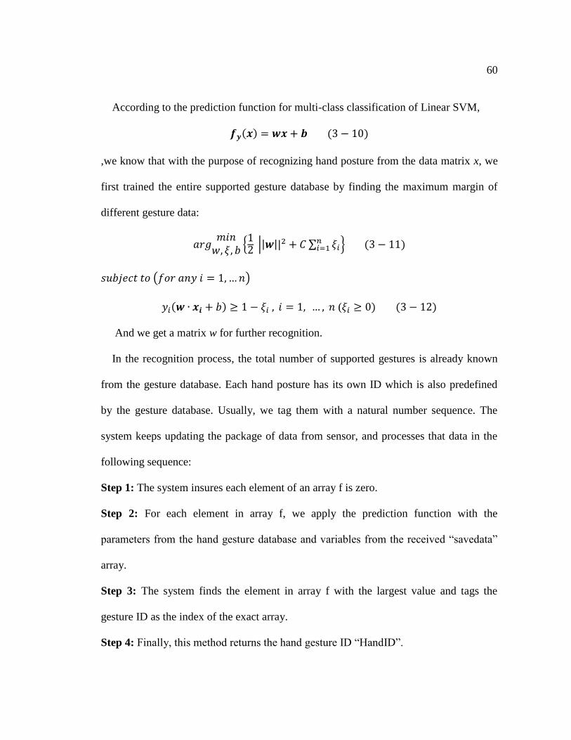
60
According to the prediction function for multi-class classification of Linear SVM,
𝒇𝒚(𝒙) = 𝒘𝒙 + 𝒃 (3 − 10)
,we know that with the purpose of recognizing hand posture from the data matrix x, we
first trained the entire supported gesture database by finding the maximum margin of
different gesture data:
𝑎𝑟𝑔𝑚𝑖𝑛
𝑤, 𝜉, 𝑏{12 ||𝒘||2 + 𝐶 ∑ 𝜉𝑖
𝑛𝑖=1 } (3 − 11)
𝑠𝑢𝑏𝑗𝑒𝑐𝑡 𝑡𝑜 (𝑓𝑜𝑟 𝑎𝑛𝑦 𝑖 = 1, … 𝑛)
𝑦𝑖(𝒘 ∙ 𝒙𝒊 + 𝑏) ≥ 1 − 𝜉𝑖 , 𝑖 = 1, … , 𝑛 (𝜉𝑖 ≥ 0) (3 − 12)
And we get a matrix w for further recognition.
In the recognition process, the total number of supported gestures is already known
from the gesture database. Each hand posture has its own ID which is also predefined
by the gesture database. Usually, we tag them with a natural number sequence. The
system keeps updating the package of data from sensor, and processes that data in the
following sequence:
Step 1: The system insures each element of an array f is zero.
Step 2: For each element in array f, we apply the prediction function with the
parameters from the hand gesture database and variables from the received “savedata”
array.
Step 3: The system finds the element in array f with the largest value and tags the
gesture ID as the index of the exact array.
Step 4: Finally, this method returns the hand gesture ID “HandID”.
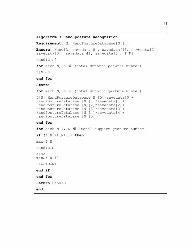
61
Algorithm 3 Hand posture Recognition
Requirement: N, HandPostureDatabase[N][7],
Ensure: HandID, savedata[0], savedata[1], savedata[2], savedata[3], savedata[4], savedata[5], f[N]
HandID ←0
for each N, N ∈ (total support posutre number)
f[N]←0
end for
Start:
for each N, N ∈ (total support gesture number)
f[N]←HandPostureDatabase[N][0]*savedata[0]+ HandPostureDatabase [N][1]*savedata[1]+ HandPostureDatabase [N][2]*savedata[2]+ HandPostureDatabase [N][3]*savedata[3]+ HandPostureDatabase [N][4]*savedata[4]+ HandPostureDatabase [N][5]
end for
for each N-1, N ∈ (total support gesture number)
if (f[N]>f[N+1]) then
max←f[N]
HandID←N
else max←f[N+1]
HandID←N+1
end if
end for
Return HandID
end
Return HandID
62
3.5 Client (Host Computer)
The client or the host computer of the proposed system varies for the purpose of the
system. When we need to utilize SVM for the determination of hand posture, the client
is responsible for both training for the gestures and recognizing them (Type 2 system).
However, if training is necessary, we just apply the recognition part to the lower
computer: microcontroller (Type 1 system).
We can connect the system to a computer as a replacement for traditional input
methods such as a mouse and a keyboard. It can also replace a joystick and provides a
more realistic gaming interaction experience. As a 3D virtual interaction device, the
system can be deployed in virtual design, assembly, and manufacturing by combining
gesture commands and voice commands. If connected with a mobile device such as a
smartphone, it can help others to understand the user’s gesture meaning.
The connection method between the system and client could also be different. A
wired connection with the computer provides a secured transmission of the signal.
Wireless connections such as Bluetooth or ZigBee [59][60] allow users to experience
the freedom, ease and the convenience of gesture-based interactions.
3.6 Summary
We proposed a multimodal data glove system as a solution for improving the
drawbacks of the current hand gesture based HCI approaches. It can recognize more
gestures, low cost and ease of use. Signal acquisition part is the first part of the system
which includes three kinds of sensors, they are resistance rheostat sensors to detect the
63
touch positon on fingers and flex sensors to measure the degree of the fingers were bent.
A motion sensor to monitor the hand posture. The signal acquisition has also been built
for these sensors. The well processed data will be sent to higher devices for recognition.
We implement two approaches for the gesture determination. Lookup table aims to deal
with the gesture kind whose data is not complex, while linear SVM we used here is to
help with determining hand posture since total of 6 dimension of data judges the hand
altitude. Client has also been discussed to discover the application of the system.
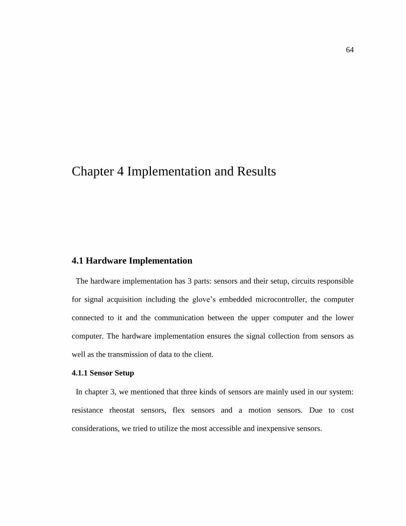
64
Chapter 4 Implementation and Results
4.1 Hardware Implementation
The hardware implementation has 3 parts: sensors and their setup, circuits responsible
for signal acquisition including the glove’s embedded microcontroller, the computer
connected to it and the communication between the upper computer and the lower
computer. The hardware implementation ensures the signal collection from sensors as
well as the transmission of data to the client.
4.1.1 Sensor Setup
In chapter 3, we mentioned that three kinds of sensors are mainly used in our system:
resistance rheostat sensors, flex sensors and a motion sensors. Due to cost
considerations, we tried to utilize the most accessible and inexpensive sensors.

65
There is already a product called the Peregrine Glove that uses embedded resistance
rheostat sensors on the fingers. We use its replacement glove (cost under 50 dollars) for
its sensors and we will install other sensors onto this glove. There are three sizes of this
product to fit different sizes of hands. In order to utilize this glove, we need to first
conclude how the sensors on the glove are connected. After doing the test, we
summarized the role of each pin for the glove shown in Figure 4.1. We re-soldered the
circuit board and left ports for ease of replacing cables for different sizes. Ports for
motion sensors have also been left for replacements. Sensors on the glove are connected
to the circuit board according to the design in Figure 3.3.
After connecting the sensors, we recorded the readings for different positions with
different actuators to build a touch command database.
Thumb Tip Actuator
Ground
Thumb Belly Actuator
Palm Acuator
Index Finger Sensor
Middle Finger Sensor
Ring Finger Sensor
Little Finger Sensor
Fig. 4.1 The function of pins on the Peregrine Glove
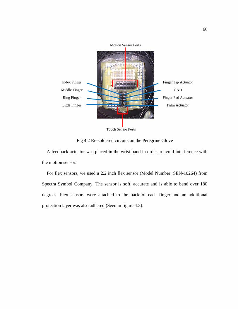
66
Finger Tip Actuator
GND
Finger Pad Actuator
Palm Actuator
Index Finger
Middle Finger
Ring Finger
Little Finger
Touch Sensor Ports
Motion Sensor Ports
Fig 4.2 Re-soldered circuits on the Peregrine Glove
A feedback actuator was placed in the wrist band in order to avoid interference with
the motion sensor.
For flex sensors, we used a 2.2 inch flex sensor (Model Number: SEN-10264) from
Spectra Symbol Company. The sensor is soft, accurate and is able to bend over 180
degrees. Flex sensors were attached to the back of each finger and an additional
protection layer was also adhered (Seen in figure 4.3).
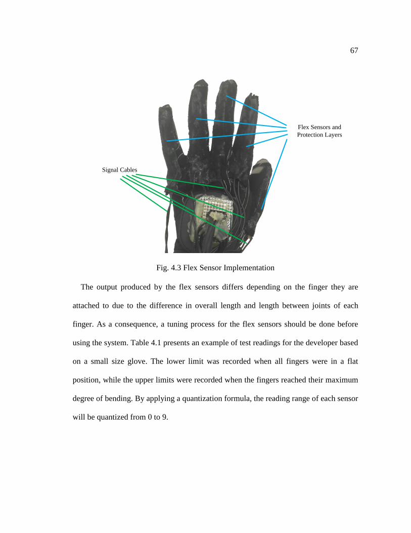
67
Flex Sensors and
Protection Layers
Signal Cables
Fig. 4.3 Flex Sensor Implementation
The output produced by the flex sensors differs depending on the finger they are
attached to due to the difference in overall length and length between joints of each
finger. As a consequence, a tuning process for the flex sensors should be done before
using the system. Table 4.1 presents an example of test readings for the developer based
on a small size glove. The lower limit was recorded when all fingers were in a flat
position, while the upper limits were recorded when the fingers reached their maximum
degree of bending. By applying a quantization formula, the reading range of each sensor
will be quantized from 0 to 9.
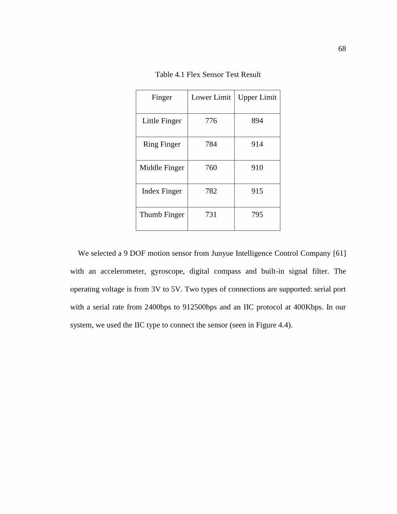
68
Table 4.1 Flex Sensor Test Result
Finger Lower Limit Upper Limit
Little Finger 776 894
Ring Finger 784 914
Middle Finger 760 910
Index Finger 782 915
Thumb Finger 731 795
We selected a 9 DOF motion sensor from Junyue Intelligence Control Company [61]
with an accelerometer, gyroscope, digital compass and built-in signal filter. The
operating voltage is from 3V to 5V. Two types of connections are supported: serial port
with a serial rate from 2400bps to 912500bps and an IIC protocol at 400Kbps. In our
system, we used the IIC type to connect the sensor (seen in Figure 4.4).
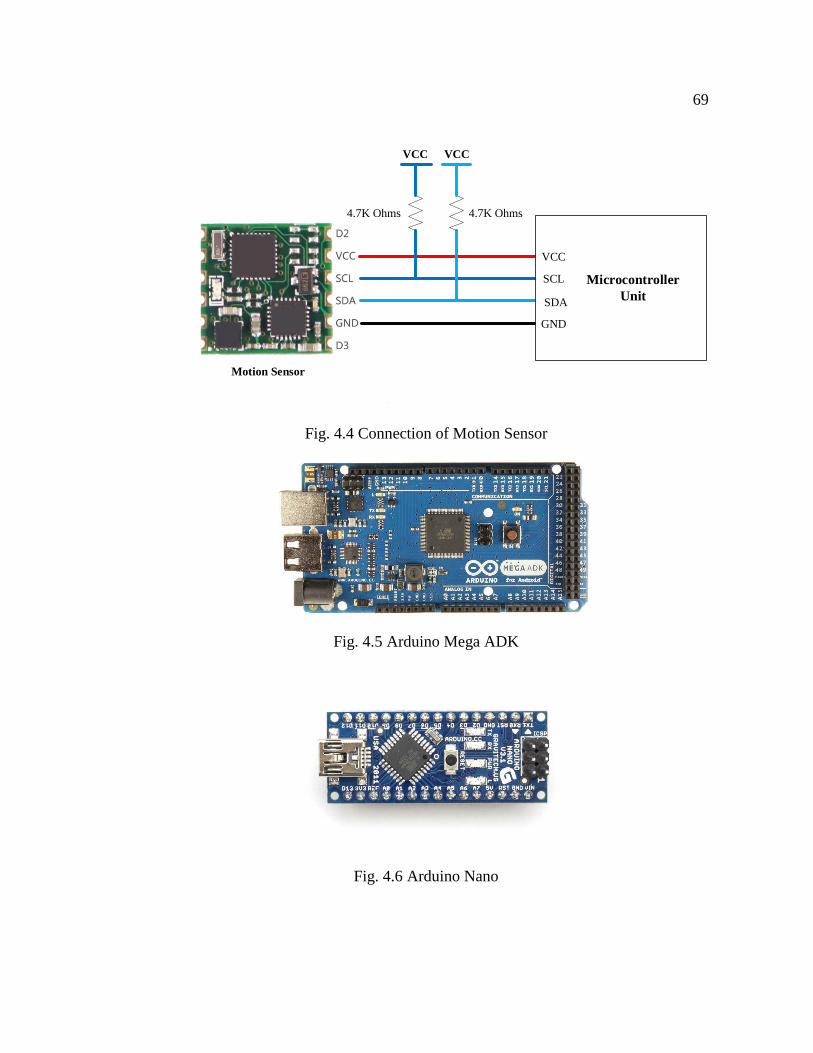
69
VCC
SCL
SDA
GND
Microcontroller
Unit
Motion Sensor
VCC VCC
4.7K Ohms4.7K Ohms
Fig. 4.4 Connection of Motion Sensor
Fig. 4.5 Arduino Mega ADK
Fig. 4.6 Arduino Nano
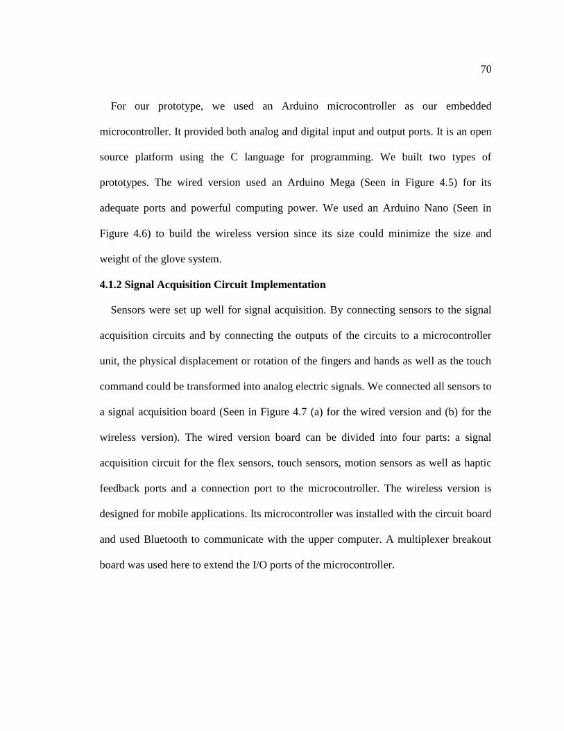
70
For our prototype, we used an Arduino microcontroller as our embedded
microcontroller. It provided both analog and digital input and output ports. It is an open
source platform using the C language for programming. We built two types of
prototypes. The wired version used an Arduino Mega (Seen in Figure 4.5) for its
adequate ports and powerful computing power. We used an Arduino Nano (Seen in
Figure 4.6) to build the wireless version since its size could minimize the size and
weight of the glove system.
4.1.2 Signal Acquisition Circuit Implementation
Sensors were set up well for signal acquisition. By connecting sensors to the signal
acquisition circuits and by connecting the outputs of the circuits to a microcontroller
unit, the physical displacement or rotation of the fingers and hands as well as the touch
command could be transformed into analog electric signals. We connected all sensors to
a signal acquisition board (Seen in Figure 4.7 (a) for the wired version and (b) for the
wireless version). The wired version board can be divided into four parts: a signal
acquisition circuit for the flex sensors, touch sensors, motion sensors as well as haptic
feedback ports and a connection port to the microcontroller. The wireless version is
designed for mobile applications. Its microcontroller was installed with the circuit board
and used Bluetooth to communicate with the upper computer. A multiplexer breakout
board was used here to extend the I/O ports of the microcontroller.
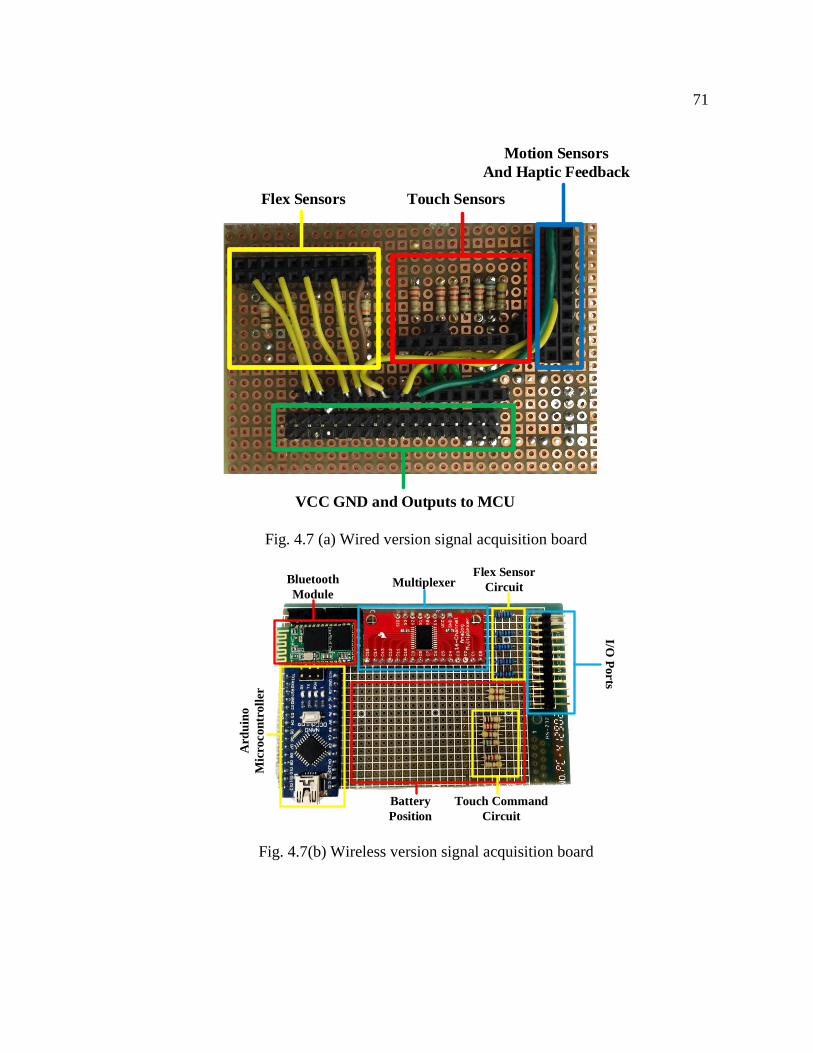
71
Flex Sensors Touch Sensors
Motion Sensors
And Haptic Feedback
VCC GND and Outputs to MCU
Fig. 4.7 (a) Wired version signal acquisition board
MultiplexerBluetooth
Module
Flex Sensor
Circuit
I/O P
orts
Touch Command
Circuit
Battery
Position
Ard
uin
o
Mic
roco
ntr
oll
er
Fig. 4.7(b) Wireless version signal acquisition board
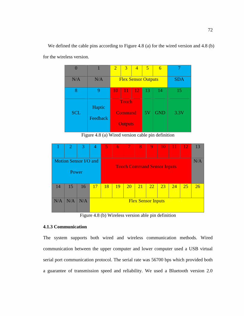
72
We defined the cable pins according to Figure 4.8 (a) for the wired version and 4.8 (b)
for the wireless version.
0 1 2 3 4 5 6 7
N/A N/A Flex Sensor Outputs SDA
8 9 10 11 12 13 14 15
SCL
Haptic
Feedback
Touch
Command
Outputs
5V GND 3.3V
Figure 4.8 (a) Wired version cable pin definition
1 2 3 4 5 6 7 8 9 10 11 12 13
Motion Sensor I/O and
Power
Touch Command Sensor Inputs
N/A
14 15 16 17 18 19 20 21 22 23 24 25 26
N/A N/A N/A Flex Sensor Inputs
Figure 4.8 (b) Wireless version able pin definition
4.1.3 Communication
The system supports both wired and wireless communication methods. Wired
communication between the upper computer and lower computer used a USB virtual
serial port communication protocol. The serial rate was 56700 bps which provided both
a guarantee of transmission speed and reliability. We used a Bluetooth version 2.0
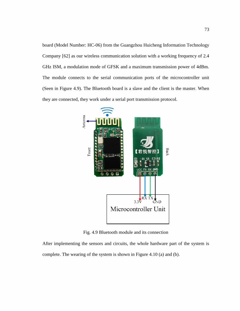
73
board (Model Number: HC-06) from the Guangzhou Huicheng Information Technology
Company [62] as our wireless communication solution with a working frequency of 2.4
GHz ISM, a modulation mode of GFSK and a maximum transmission power of 4dBm.
The module connects to the serial communication ports of the microcontroller unit
(Seen in Figure 4.9). The Bluetooth board is a slave and the client is the master. When
they are connected, they work under a serial port transmission protocol.
Fig. 4.9 Bluetooth module and its connection
After implementing the sensors and circuits, the whole hardware part of the system is
complete. The wearing of the system is shown in Figure 4.10 (a) and (b).
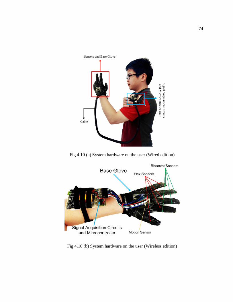
74
Sensors and Base Glove
Sig
nal A
cquisitio
n C
ircuits
and M
icrocontro
ller U
nit
Cable
Fig 4.10 (a) System hardware on the user (Wired edition)
Fig 4.10 (b) System hardware on the user (Wireless edition)
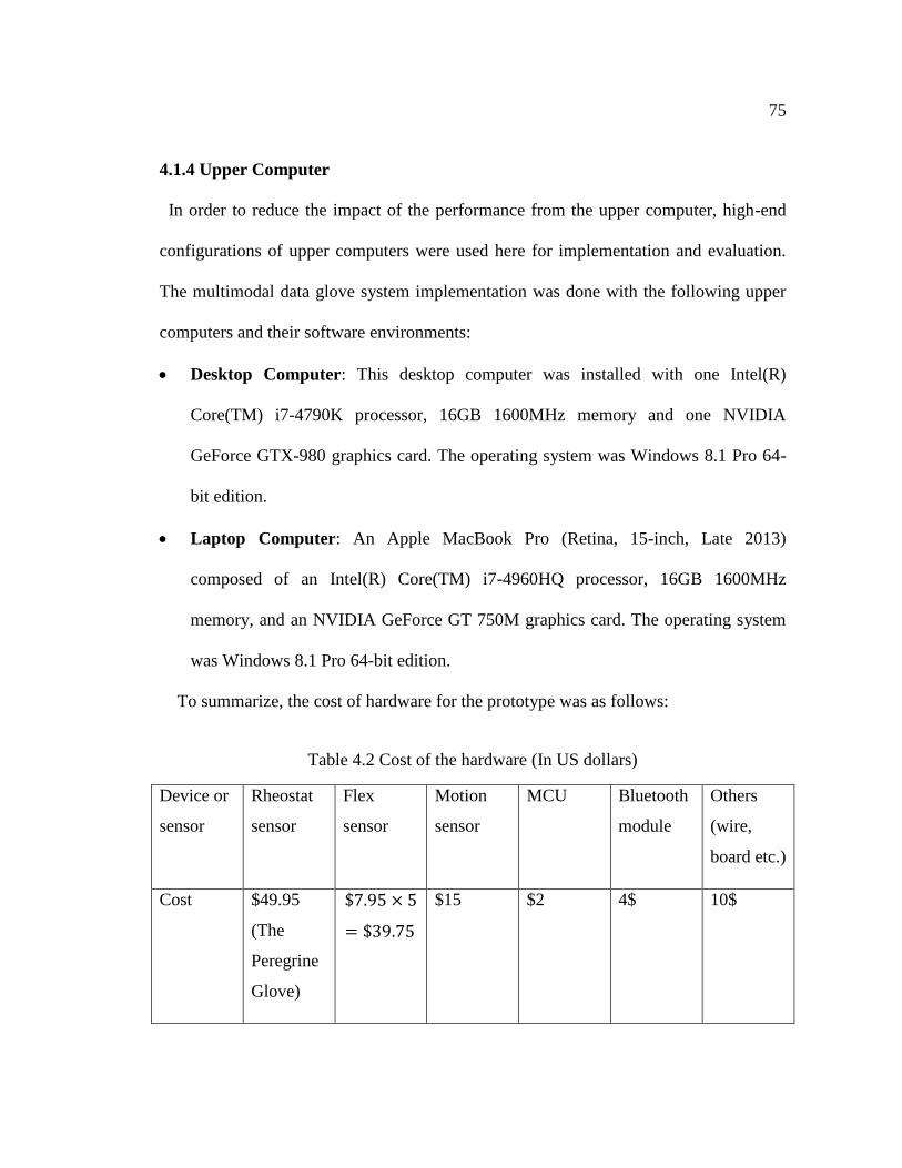
75
4.1.4 Upper Computer
In order to reduce the impact of the performance from the upper computer, high-end
configurations of upper computers were used here for implementation and evaluation.
The multimodal data glove system implementation was done with the following upper
computers and their software environments:
Desktop Computer: This desktop computer was installed with one Intel(R)
Core(TM) i7-4790K processor, 16GB 1600MHz memory and one NVIDIA
GeForce GTX-980 graphics card. The operating system was Windows 8.1 Pro 64-
bit edition.
Laptop Computer: An Apple MacBook Pro (Retina, 15-inch, Late 2013)
composed of an Intel(R) Core(TM) i7-4960HQ processor, 16GB 1600MHz
memory, and an NVIDIA GeForce GT 750M graphics card. The operating system
was Windows 8.1 Pro 64-bit edition.
To summarize, the cost of hardware for the prototype was as follows:
Table 4.2 Cost of the hardware (In US dollars)
Device or
sensor
Rheostat
sensor
Flex
sensor
Motion
sensor
MCU Bluetooth
module
Others
(wire,
board etc.)
Cost $49.95
(The
Peregrine
Glove)
$7.95 × 5
= $39.75
$15 $2 4$ 10$
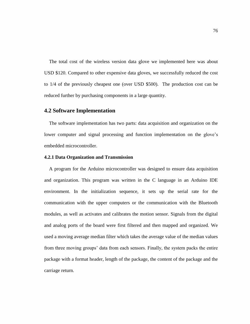
76
The total cost of the wireless version data glove we implemented here was about
USD $120. Compared to other expensive data gloves, we successfully reduced the cost
to 1/4 of the previously cheapest one (over USD $500). The production cost can be
reduced further by purchasing components in a large quantity.
4.2 Software Implementation
The software implementation has two parts: data acquisition and organization on the
lower computer and signal processing and function implementation on the glove’s
embedded microcontroller.
4.2.1 Data Organization and Transmission
A program for the Arduino microcontroller was designed to ensure data acquisition
and organization. This program was written in the C language in an Arduino IDE
environment. In the initialization sequence, it sets up the serial rate for the
communication with the upper computers or the communication with the Bluetooth
modules, as well as activates and calibrates the motion sensor. Signals from the digital
and analog ports of the board were first filtered and then mapped and organized. We
used a moving average median filter which takes the average value of the median values
from three moving groups’ data from each sensors. Finally, the system packs the entire
package with a format header, length of the package, the content of the package and the
carriage return.
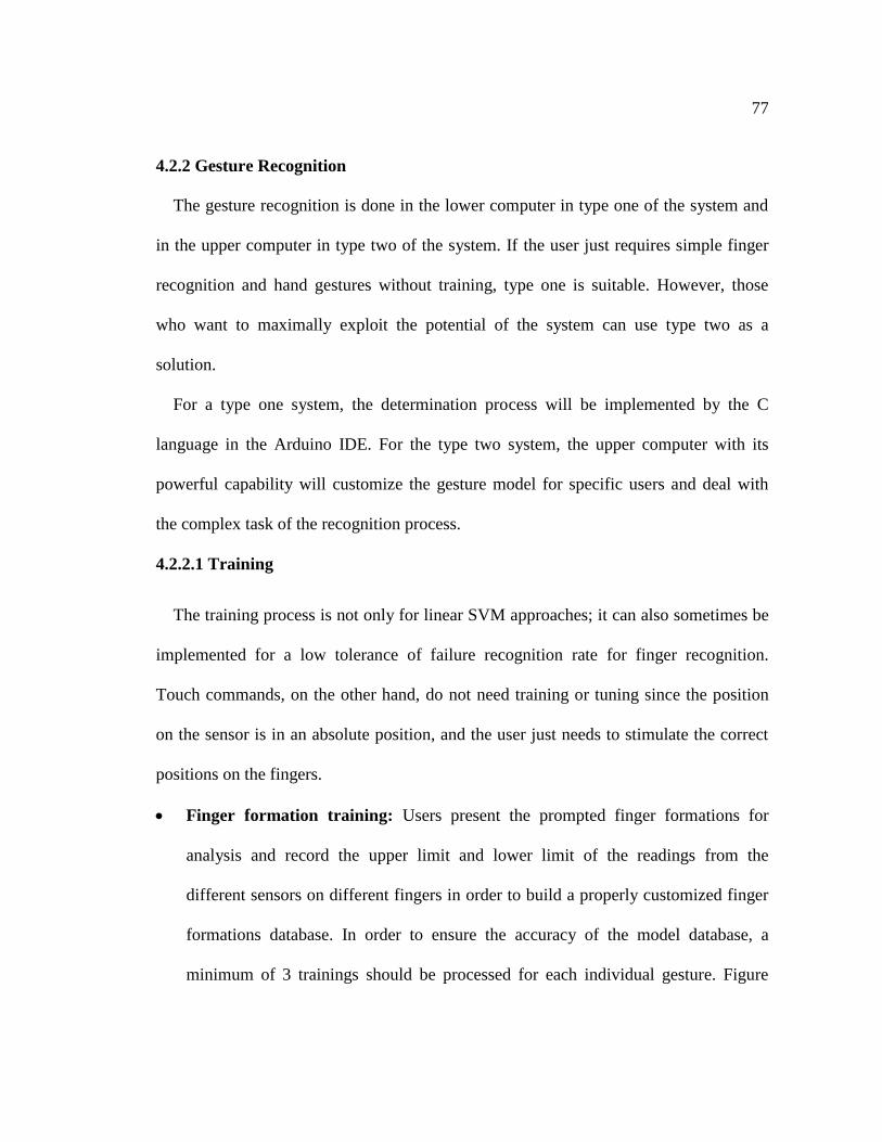
77
4.2.2 Gesture Recognition
The gesture recognition is done in the lower computer in type one of the system and
in the upper computer in type two of the system. If the user just requires simple finger
recognition and hand gestures without training, type one is suitable. However, those
who want to maximally exploit the potential of the system can use type two as a
solution.
For a type one system, the determination process will be implemented by the C
language in the Arduino IDE. For the type two system, the upper computer with its
powerful capability will customize the gesture model for specific users and deal with
the complex task of the recognition process.
4.2.2.1 Training
The training process is not only for linear SVM approaches; it can also sometimes be
implemented for a low tolerance of failure recognition rate for finger recognition.
Touch commands, on the other hand, do not need training or tuning since the position
on the sensor is in an absolute position, and the user just needs to stimulate the correct
positions on the fingers.
Finger formation training: Users present the prompted finger formations for
analysis and record the upper limit and lower limit of the readings from the
different sensors on different fingers in order to build a properly customized finger
formations database. In order to ensure the accuracy of the model database, a
minimum of 3 trainings should be processed for each individual gesture. Figure
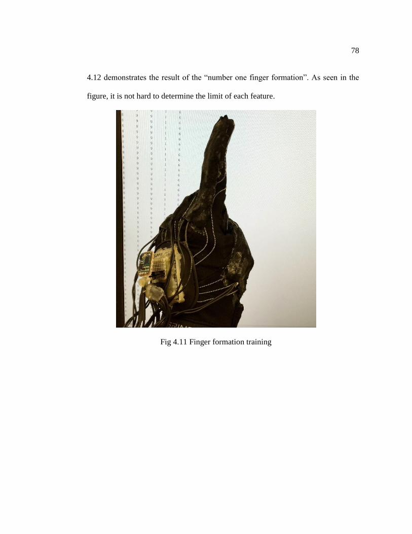
78
4.12 demonstrates the result of the “number one finger formation”. As seen in the
figure, it is not hard to determine the limit of each feature.
Fig 4.11 Finger formation training
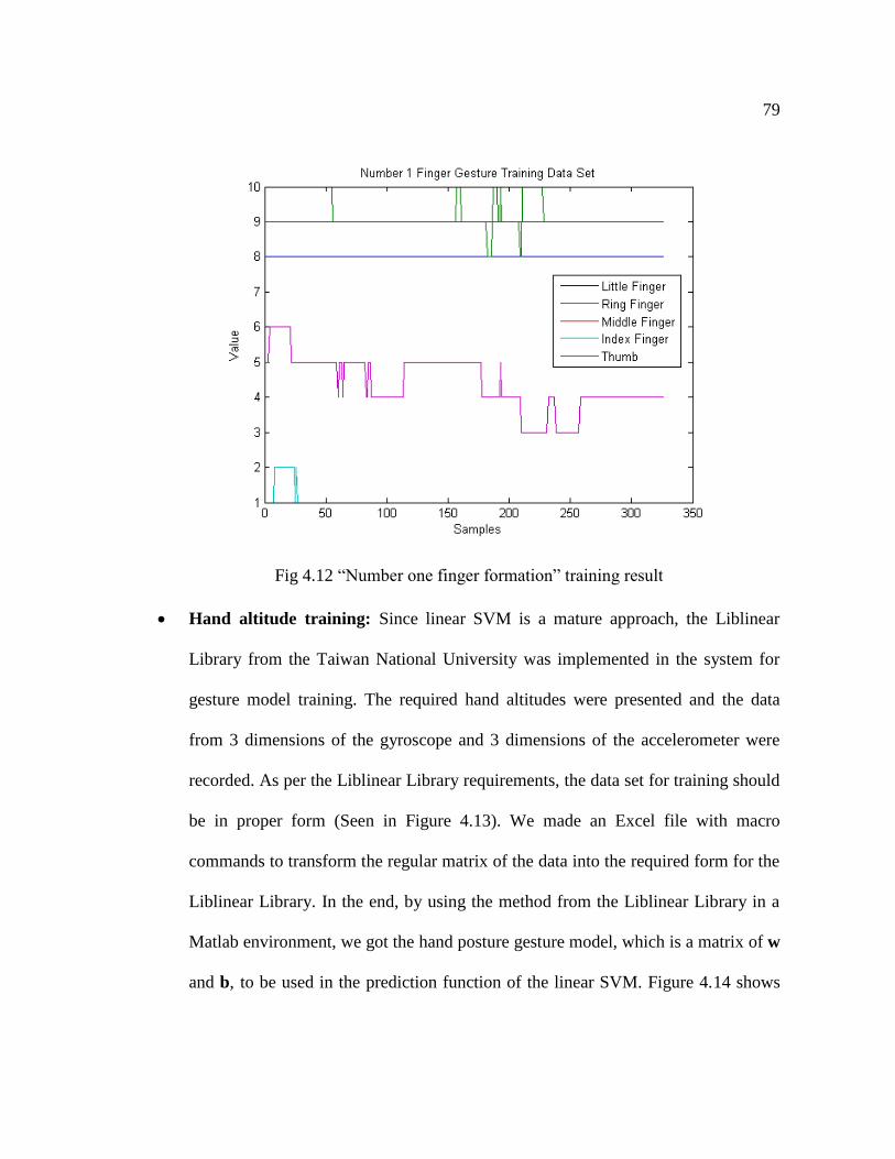
79
Fig 4.12 “Number one finger formation” training result
Hand altitude training: Since linear SVM is a mature approach, the Liblinear
Library from the Taiwan National University was implemented in the system for
gesture model training. The required hand altitudes were presented and the data
from 3 dimensions of the gyroscope and 3 dimensions of the accelerometer were
recorded. As per the Liblinear Library requirements, the data set for training should
be in proper form (Seen in Figure 4.13). We made an Excel file with macro
commands to transform the regular matrix of the data into the required form for the
Liblinear Library. In the end, by using the method from the Liblinear Library in a
Matlab environment, we got the hand posture gesture model, which is a matrix of w
and b, to be used in the prediction function of the linear SVM. Figure 4.14 shows
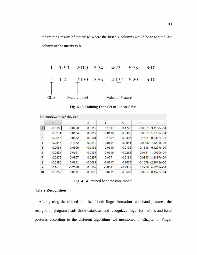
80
the training results of matrix w, where the first six columns would be w and the last
column of the matrix is b.
1 1: 90 2:100 3:34 4:23 5:75 6:10
2 1: 4 2:130 3:55 4:132 5:20 6:10
Class Feature Label Value of Feature
Fig. 4.13 Training Data Set of Linear SVM
Fig. 4.14 Trained hand posture model
4.2.2.2 Recognition
After getting the trained models of both finger formations and hand postures, the
recognition program reads those databases and recognizes finger formations and hand
postures according to the different algorithms we mentioned in Chapter 3. Finger
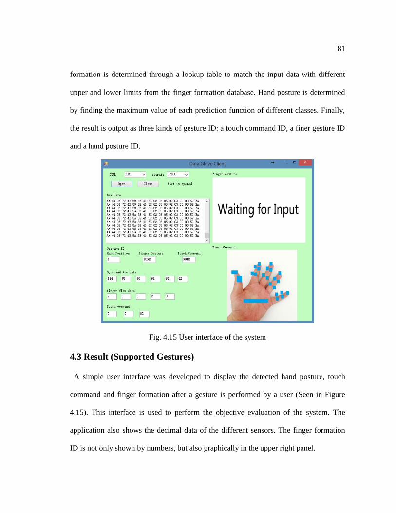
81
formation is determined through a lookup table to match the input data with different
upper and lower limits from the finger formation database. Hand posture is determined
by finding the maximum value of each prediction function of different classes. Finally,
the result is output as three kinds of gesture ID: a touch command ID, a finer gesture ID
and a hand posture ID.
Fig. 4.15 User interface of the system
4.3 Result (Supported Gestures)
A simple user interface was developed to display the detected hand posture, touch
command and finger formation after a gesture is performed by a user (Seen in Figure
4.15). This interface is used to perform the objective evaluation of the system. The
application also shows the decimal data of the different sensors. The finger formation
ID is not only shown by numbers, but also graphically in the upper right panel.
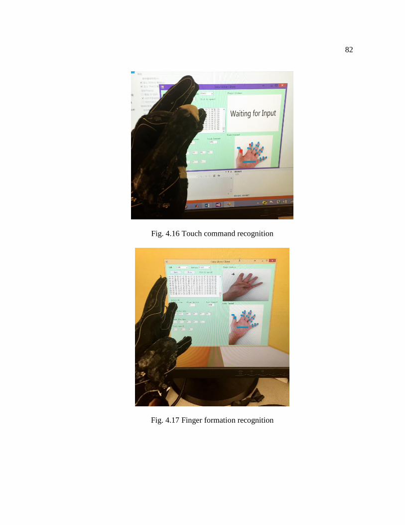
82
Fig. 4.16 Touch command recognition
Fig. 4.17 Finger formation recognition
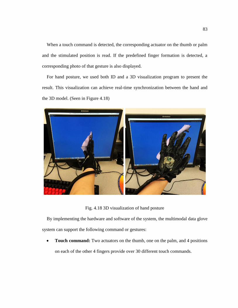
83
When a touch command is detected, the corresponding actuator on the thumb or palm
and the stimulated position is read. If the predefined finger formation is detected, a
corresponding photo of that gesture is also displayed.
For hand posture, we used both ID and a 3D visualization program to present the
result. This visualization can achieve real-time synchronization between the hand and
the 3D model. (Seen in Figure 4.18)
Fig. 4.18 3D visualization of hand posture
By implementing the hardware and software of the system, the multimodal data glove
system can support the following command or gestures:
Touch command: Two actuators on the thumb, one on the palm, and 4 positions
on each of the other 4 fingers provide over 30 different touch commands.
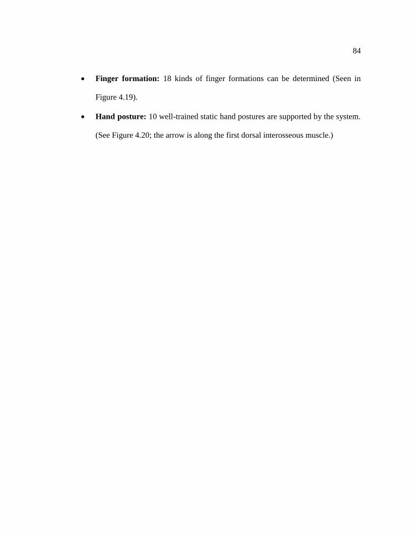
84
Finger formation: 18 kinds of finger formations can be determined (Seen in
Figure 4.19).
Hand posture: 10 well-trained static hand postures are supported by the system.
(See Figure 4.20; the arrow is along the first dorsal interosseous muscle.)
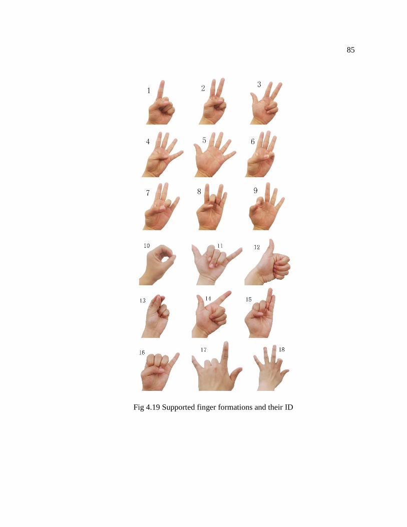
85
Fig 4.19 Supported finger formations and their ID
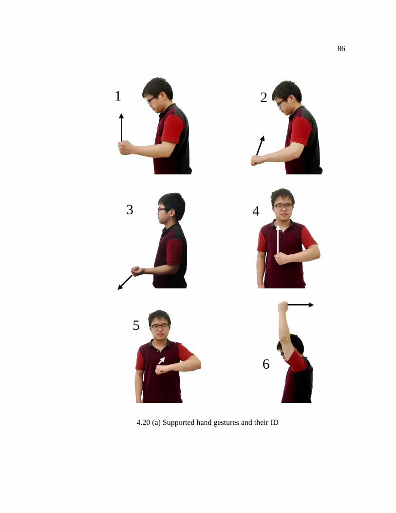
86
1 2
3
5
6
3 4
4.20 (a) Supported hand gestures and their ID
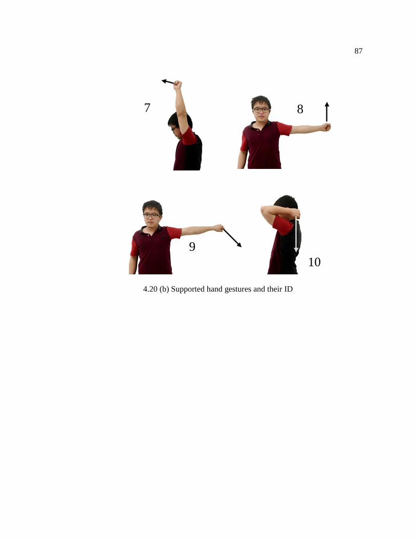
87
7 8
9
10
4.20 (b) Supported hand gestures and their ID
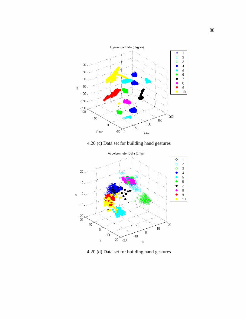
88
4.20 (c) Data set for building hand gestures
4.20 (d) Data set for building hand gestures
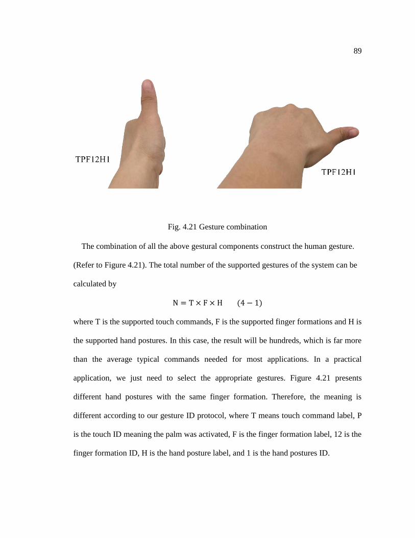
89
Fig. 4.21 Gesture combination
The combination of all the above gestural components construct the human gesture.
(Refer to Figure 4.21). The total number of the supported gestures of the system can be
calculated by
N = T × F × H (4 − 1)
where T is the supported touch commands, F is the supported finger formations and H is
the supported hand postures. In this case, the result will be hundreds, which is far more
than the average typical commands needed for most applications. In a practical
application, we just need to select the appropriate gestures. Figure 4.21 presents
different hand postures with the same finger formation. Therefore, the meaning is
different according to our gesture ID protocol, where T means touch command label, P
is the touch ID meaning the palm was activated, F is the finger formation label, 12 is the
finger formation ID, H is the hand posture label, and 1 is the hand postures ID.
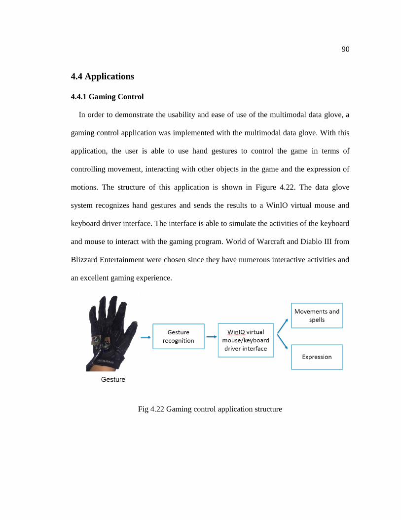
90
4.4 Applications
4.4.1 Gaming Control
In order to demonstrate the usability and ease of use of the multimodal data glove, a
gaming control application was implemented with the multimodal data glove. With this
application, the user is able to use hand gestures to control the game in terms of
controlling movement, interacting with other objects in the game and the expression of
motions. The structure of this application is shown in Figure 4.22. The data glove
system recognizes hand gestures and sends the results to a WinIO virtual mouse and
keyboard driver interface. The interface is able to simulate the activities of the keyboard
and mouse to interact with the gaming program. World of Warcraft and Diablo III from
Blizzard Entertainment were chosen since they have numerous interactive activities and
an excellent gaming experience.
Fig 4.22 Gaming control application structure
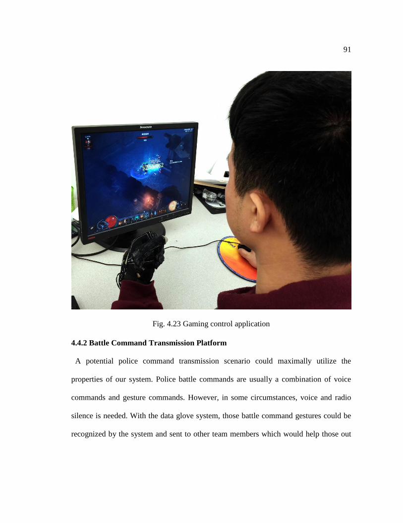
91
Fig. 4.23 Gaming control application
4.4.2 Battle Command Transmission Platform
A potential police command transmission scenario could maximally utilize the
properties of our system. Police battle commands are usually a combination of voice
commands and gesture commands. However, in some circumstances, voice and radio
silence is needed. With the data glove system, those battle command gestures could be
recognized by the system and sent to other team members which would help those out
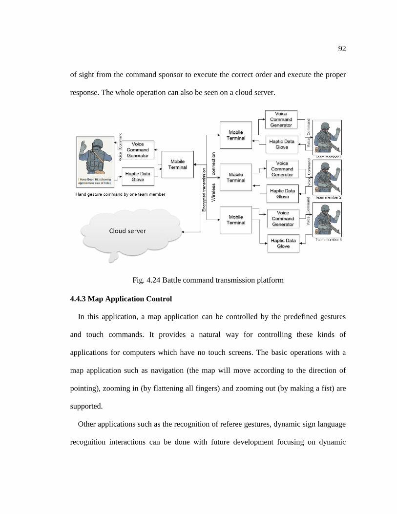
92
of sight from the command sponsor to execute the correct order and execute the proper
response. The whole operation can also be seen on a cloud server.
Fig. 4.24 Battle command transmission platform
4.4.3 Map Application Control
In this application, a map application can be controlled by the predefined gestures
and touch commands. It provides a natural way for controlling these kinds of
applications for computers which have no touch screens. The basic operations with a
map application such as navigation (the map will move according to the direction of
pointing), zooming in (by flattening all fingers) and zooming out (by making a fist) are
supported.
Other applications such as the recognition of referee gestures, dynamic sign language
recognition interactions can be done with future development focusing on dynamic
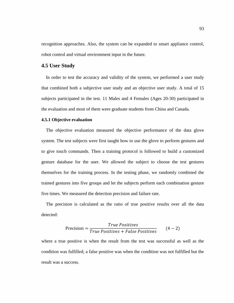
93
recognition approaches. Also, the system can be expanded to smart appliance control,
robot control and virtual environment input in the future.
4.5 User Study
In order to test the accuracy and validity of the system, we performed a user study
that combined both a subjective user study and an objective user study. A total of 15
subjects participated in the test. 11 Males and 4 Females (Ages 20-30) participated in
the evaluation and most of them were graduate students from China and Canada.
4.5.1 Objective evaluation
The objective evaluation measured the objective performance of the data glove
system. The test subjects were first taught how to use the glove to perform gestures and
to give touch commands. Then a training protocol is followed to build a customized
gesture database for the user. We allowed the subject to choose the test gestures
themselves for the training process. In the testing phase, we randomly combined the
trained gestures into five groups and let the subjects perform each combination gesture
five times. We measured the detection precision and failure rate.
The precision is calculated as the ratio of true positive results over all the data
detected:
Precision =𝑇𝑟𝑢𝑒 𝑃𝑜𝑠𝑖𝑡𝑖𝑣𝑒𝑠
𝑇𝑟𝑢𝑒 𝑃𝑜𝑠𝑖𝑡𝑖𝑣𝑒𝑠 + 𝐹𝑎𝑙𝑠𝑒 𝑃𝑜𝑠𝑖𝑡𝑖𝑣𝑒𝑠 (4 − 2)
where a true positive is when the result from the test was successful as well as the
condition was fulfilled; a false positive was when the condition was not fulfilled but the
result was a success.
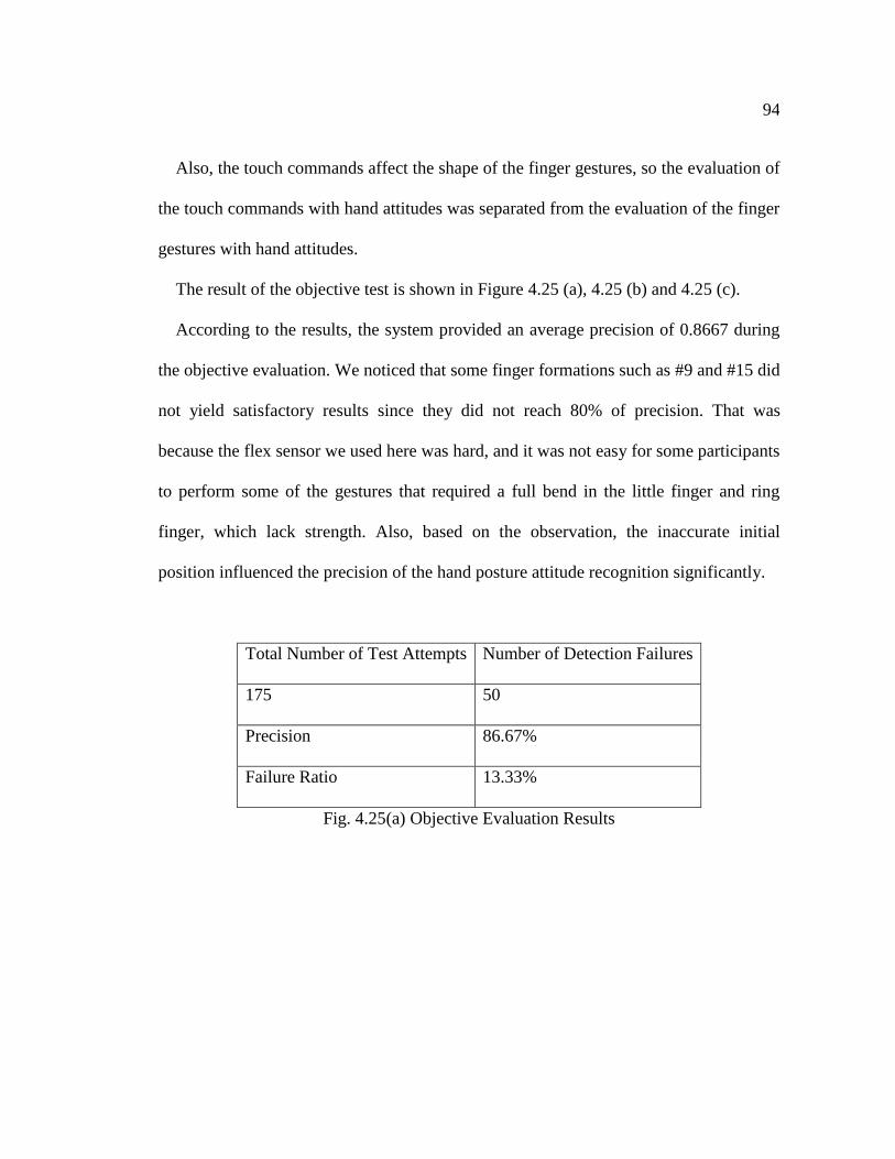
94
Also, the touch commands affect the shape of the finger gestures, so the evaluation of
the touch commands with hand attitudes was separated from the evaluation of the finger
gestures with hand attitudes.
The result of the objective test is shown in Figure 4.25 (a), 4.25 (b) and 4.25 (c).
According to the results, the system provided an average precision of 0.8667 during
the objective evaluation. We noticed that some finger formations such as #9 and #15 did
not yield satisfactory results since they did not reach 80% of precision. That was
because the flex sensor we used here was hard, and it was not easy for some participants
to perform some of the gestures that required a full bend in the little finger and ring
finger, which lack strength. Also, based on the observation, the inaccurate initial
position influenced the precision of the hand posture attitude recognition significantly.
Total Number of Test Attempts Number of Detection Failures
175 50
Precision 86.67%
Failure Ratio 13.33%
Fig. 4.25(a) Objective Evaluation Results
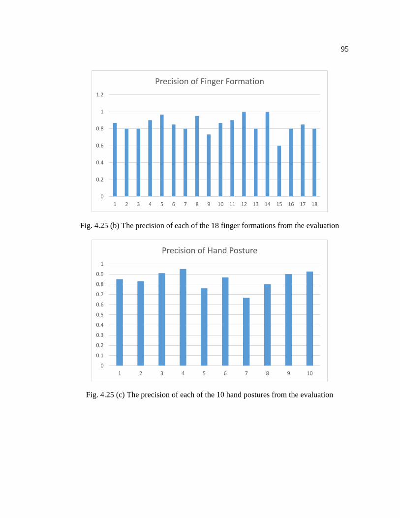
95
Fig. 4.25 (b) The precision of each of the 18 finger formations from the evaluation
Fig. 4.25 (c) The precision of each of the 10 hand postures from the evaluation
0
0.2
0.4
0.6
0.8
1
1.2
1 2 3 4 5 6 7 8 9 10 11 12 13 14 15 16 17 18
Precision of Finger Formation
0
0.1
0.2
0.3
0.4
0.5
0.6
0.7
0.8
0.9
1
1 2 3 4 5 6 7 8 9 10
Precision of Hand Posture
96
4.5.2 Subjective User Study
The subjective user study aimed to measure the validity of the multimodal data glove.
By implementing the gaming control application, the system provided an alternative
method of gaming interaction. World of Warcraft and Diablo III were used in this user
study. Subjects were first taught how to play the game using the traditional input
methods: keyboards and mouse. Then subjects were asked to complete some objectives
in the game. Then, subjects were taught how to use the glove system and performed the
training process to build the hand gesture database with which they were more familiar.
Subjects performed the same tasks that they did by keyboard and mouse. Finally, a
questionnaire (See Appendix) was completed by subjects to evaluate their experience
during the test. In order to avoid the influence from the keyboard method experience,
for those who have played World of Warcraft or Diablo III were asked to evaluate the
experience of the game they had not played only. In the end of the subjective user study,
two marks of user experience were collected from the participants and we performed a
two-tail paired-samples T-test. We expected the user experience of the glove would be
better than the keyboard interaction method.
The results are shown in Table 4.3 and Figure 4.26. The results of the first two
questions suggests that participants had more of a tendency to believe that they were
more in control of the game when using the glove system. Answers to question 3 and 4
suggest that they could trigger the commands correctly both on the glove and the
keyboard. Results of question 5 demonstrated that participants thought it was more fun
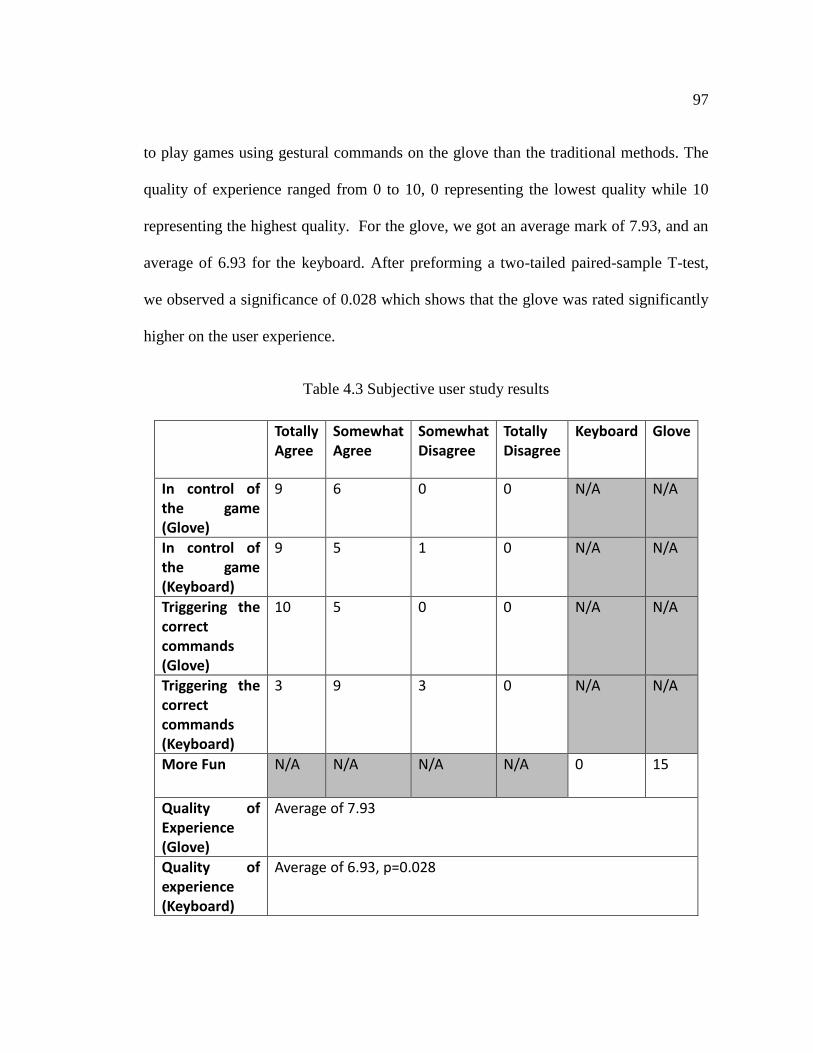
97
to play games using gestural commands on the glove than the traditional methods. The
quality of experience ranged from 0 to 10, 0 representing the lowest quality while 10
representing the highest quality. For the glove, we got an average mark of 7.93, and an
average of 6.93 for the keyboard. After preforming a two-tailed paired-sample T-test,
we observed a significance of 0.028 which shows that the glove was rated significantly
higher on the user experience.
Table 4.3 Subjective user study results
Totally Agree
Somewhat Agree
Somewhat Disagree
Totally Disagree
Keyboard Glove
In control of the game (Glove)
9 6 0 0 N/A N/A
In control of the game (Keyboard)
9 5 1 0 N/A N/A
Triggering the correct commands (Glove)
10 5 0 0 N/A N/A
Triggering the correct commands (Keyboard)
3 9 3 0 N/A N/A
More Fun N/A N/A N/A N/A 0 15
Quality of Experience (Glove)
Average of 7.93
Quality of experience (Keyboard)
Average of 6.93, p=0.028
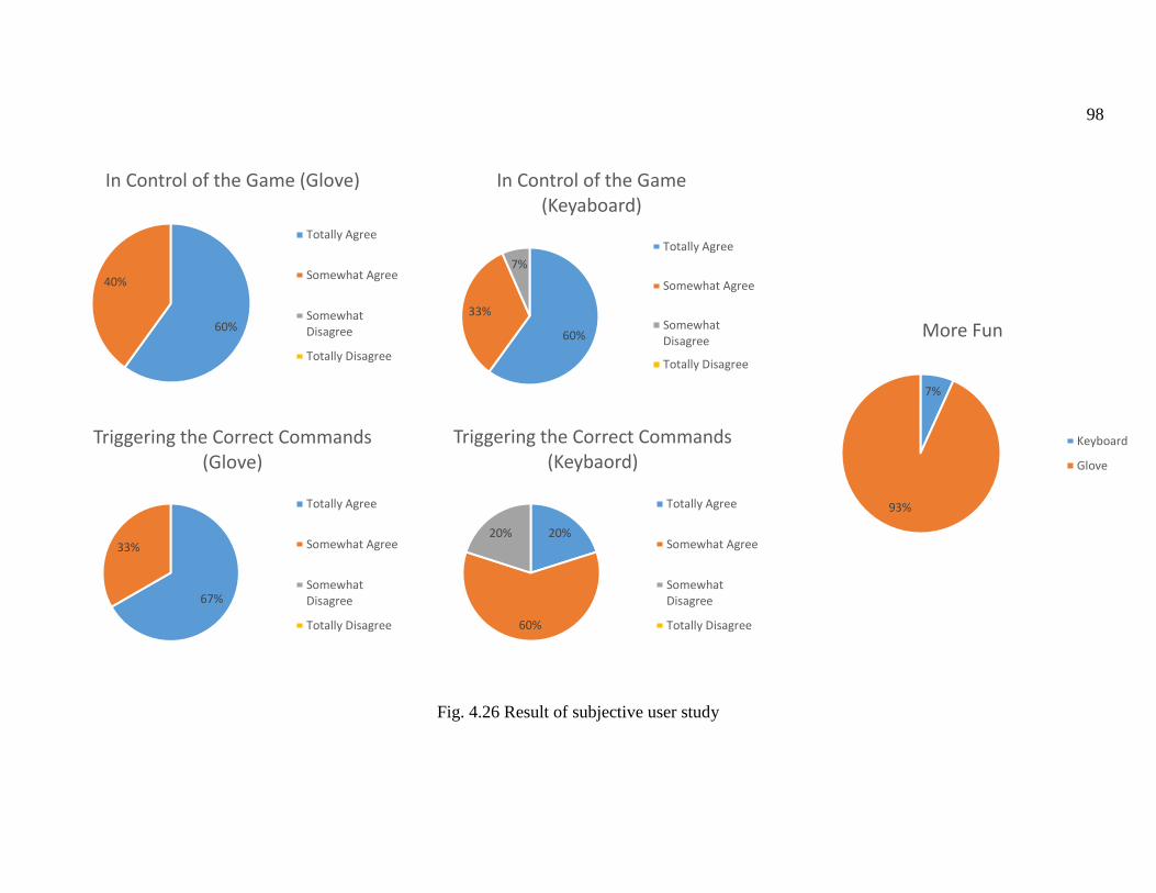
98
7%
93%
More Fun
Keyboard
Glove
Fig. 4.26 Result of subjective user study
60%
40%
In Control of the Game (Glove)
Totally Agree
Somewhat Agree
SomewhatDisagree
Totally Disagree
60%
33%
7%
In Control of the Game (Keyaboard)
Totally Agree
Somewhat Agree
SomewhatDisagree
Totally Disagree
67%
33%
Triggering the Correct Commands (Glove)
Totally Agree
Somewhat Agree
SomewhatDisagree
Totally Disagree
20%
60%
20%
Triggering the Correct Commands (Keybaord)
Totally Agree
Somewhat Agree
SomewhatDisagree
Totally Disagree
99
4.6 Summary
This chapter mainly present implementation of the proposed system. In hardware
implementation section, we introduced that the choice of the different sensors, and the
process of building the circuits. We also introduced the implementation of the hardware
level of communication approach for the system. In the software implementation
section, we introduced the process of data organizing and transmitting. Liblinear SVM
library was used here as the linear SVM training tool. We have shown that the the
system supports hundreds of different gestures. In order to measure the validity and ease
of use of the multimodal data glove system, an objective user study has been performed
to prove the system’s high recognition precision (86.67%). Furthermore, a subjective
study has been conducted to summarize the subjective experience of a sample of users.
100
Chapter 5 Conclusion and Future Work
5.1 Conclusion
With the development and expending need of the wearable devices, users are
increasingly looking for a natural ways to interact with computing devices such as
personal computers, cellphones, tablets etc. In this thesis, we studied the previous
research works and products pertaining hand gesture interaction and proposed a new
solution in this field: the multimodal data glove system which supports hundreds of
gestures, cost very low and very easy to use.
In Chapter 3, we introduced the requirements of the proposed system. We presented
the proposed system, from the broad structure to a detailed design. We explained the
signal acquisition process, including the resistance rheostat sensor, flex sensor and
motion sensor as well as their operating principles, and we also explained two methods:
101
a lookup table and a Linear Support Vector Machine for recognizing the three kinds of
gesture commands. In the end, we summarized the client of the proposed system.
In Chapter 4, by introducing the setup of sensors, the signal acquisition circuit, the
communication from sensor to microcontroller and from the microcontroller to upper
computer this chapter presents the hardware implementation of the proposed
multimodal data glove system. This chapter also introduced implementation of software
which refers to the process of data and visualizing the results. Application was also been
discussed. And it concluded the validity and accuracy of the proposed system by
providing a user study including subjective side and objective side.
5.2 Future Work
Currently, the system can only recognize static gestures, we will continue to work
on the recognition of dynamic gestures. And this will expend the potential application
into more areas. Also, we now just used one flex sensor on each finger to detect the
finger movement. Even though this setup could already provide a significant number of
gestures, more sensor can be added between the fingers to measure the relative
horizontal movement of fingers. At last, more and more feasible application will be
developed to make the system more comprehensive.
102
Bibliography
[1] L. E. Dunne, “The Design of Wearable Technology: Addressing the Human-
Device Interface through Functional Apparel Design,” 2004.
[2] “Google Glass.” [Online]. Available: https://www.google.com/glass/start/.
[Accessed: 02-May-2015].
[3] “Moto 360 by Motorola.” [Online]. Available:
http://www.motorola.ca/consumers/moto-360-ca-en/Moto-360/moto-360-ca-
en.html. [Accessed: 02-May-2015].
[4] “Samsung Gear.” [Online]. Available:
http://www.samsung.com/ca/consumer/mobile/galaxy-gear/. [Accessed: 02-May-
2015].
[5] “Apple (Canada) - Apple Watch.” [Online]. Available:
http://www.apple.com/ca/watch/. [Accessed: 02-May-2015].
[6] J. Derrick, “Morgan Stanley: Wearable Technology A Potential $1.6 Trillion
Business: Apple Inc., Alibaba Group Holding Ltd | Benzinga,” Benzinga, 20-
Dec-2014.
103
[7] “Standardized Hand Signals For Close Range Engagement (C.R.E.) Operations.”
[Online]. Available: http://www.lefande.com/hands.html. [Accessed: 02-May-
2015].
[8] S. Goldin-Meadow, Hearing Gesture: How Our Hands Help Us Think. Harvard
University Press, 2005.
[9] S. Mitra and T. Acharya, “Gesture Recognition : A Survey,” IEEE Trans. Syst.
Man, Cybern. - Part C Appl. Rev., vol. 37, no. 3, pp. 311–324, 2007.
[10] A. Chaudhary, J. . Raheja, K. Das, and S. Raheja, “Intelligent Approaches to
interact with Machines using Hand Gesture Recognition in Natural way: A
Survey,” Int. J. Comput. Sci. Eng. Surv., vol. 2, no. 1, pp. 122–133, 2011.
[11] P. Bull, “Book Review: Gesture: Visible action as utterance,” J. Lang. Soc.
Psychol., 2006.
[12] R. Tennant and M. Brown, The American sign language handshape dictionary.
Gallaudet University Press, 1998.
[13] J. LaViola, “A survey of hand posture and gesture recognition techniques and
technology,” Brown Univ. Provid. RI, 1999.

104
[14] V. Pavlovic, R. Sharma, and T. Huang, “Visual interpretation of hand gestures
for human-computer interaction: A review,” Pattern Anal. Mach. Intell. IEEE
Trans., vol. 19, no. 7, pp. 677–695, 1997.
[15] R. S. Indrajit Poddar, Yogesh Sethi, Ercan Ozyildiz, “Toward Natural
Gesture/Speech HCI: A Case Study of Weather Narration,” in Perceptual User
Interfaces, 1998, pp. 1–6.
[16] S. Rautaray, A. Kumar, and A. Agrawal, Human computer interaction with hand
gestures in virtual environment. Springer Berlin Heidelberg, 2012.
[17] “The Peregrine Glove.” [Online]. Available: http://theperegrine.com/. [Accessed:
06-May-2015].
[18] R. Deshayes, C. Jacquet, C. Hardebolle, F. Boulanger, and T. Mens,
“Heterogeneous modeling of gesture-based 3D applications,” in Proceedings of
the 6th International Workshop on Multi-Paradigm Modeling - MPM ’12, 2012,
pp. 19–24.
[19] A. Malima, E. Ozgur, and M. Cetin, “A Fast Algorithm for Vision-Based Hand
Gesture Recognition for Robot Control,” in 2006 IEEE 14th Signal Processing
and Communications Applications, 2006, pp. 1–4.

105
[20] Z. Zafrulla, H. Brashear, T. Starner, H. Hamilton, and P. Presti, “American sign
language recognition with the kinect,” in Proceedings of the 13th international
conference on multimodal interfaces - ICMI ’11, 2011, p. 279.
[21] H. Cooper, N. Pugeault, and R. Bowden, “Sign Language Recognition using
Sequential Pattern Trees,” in 2012 IEEE Conference on Computer Vision and
Pattern Recognition, 2012, pp. 2200–2207.
[22] J. Song, G. Sörös, F. Pece, S. R. Fanello, S. Izadi, C. Keskin, and O. Hilliges,
“In-air gestures around unmodified mobile devices,” in Proceedings of the 27th
annual ACM symposium on User interface software and technology - UIST ’14,
2014, pp. 319–329.
[23] S. P. Arjunan, H. Weghorn, J. O’Connor, D. Kumar, S. Shahebjada, and T.
Bastos, “Towards better real-time control of smart wheelchair using subtle finger
movements via wireless (blue-tooth) interface,” in 2012 4th International
Conference on Intelligent Human Computer Interaction (IHCI), 2012, pp. 1–5.
[24] S. Thiemjarus and S. Dwivedi, “A HCI application for aiding children with
mental disorders,” in i-CREATe ’13 Proceedings of the 7th International
Convention on Rehabilitation Engineering and Assistive Technology, 2013, p. 50.
106
[25] C. Nolker and H. Ritter, “Visual recognition of continuous hand postures,”
Neural Networks, IEEE Trans., 2002.
[26] D. Nguyen, T. Pham, and J. Jeon, “Fingertip detection with morphology and
geometric calculation,” in Intelligent Robots and Systems, 2009.
[27] C. Ng and S. Ranganath, “Real-time gesture recognition system and application,”
Image Vis. Comput., vol. 20, no. 13, pp. 993–1007, 2002.
[28] J. Lin, Y. Wu, and T. Huang, “Modeling the constraints of human hand motion,”
in Human Motion, 2000. Proceedings. Workshop on, 2000, pp. 121–126.
[29] C.-C. Lien and C.-L. Huang, “Model-based articulated hand motion tracking for
gesture recognition,” Image Vis. Comput., vol. 16, no. 2, pp. 121–134, Feb. 1998.
[30] F. Tsalakanidou, F. Forster, S. Malassiotis, and M. Strintzis, “Real-time
acquisition of depth and color images using structured light and its application to
3D face recognition,” Real-Time Imaging, 2005.
[31] L. Campbell and D. Becker, “Invariant features for 3-D gesture recognition,” in
2013 10th IEEE International Conference and Workshops on Automatic Face
and Gesture Recognition (FG), 2013.
107
[32] M. Turk and T. S. Huang, “Gesture modeling and recognition using finite state
machines,” in Proceedings Fourth IEEE International Conference on Automatic
Face and Gesture Recognition (Cat. No. PR00580), 2000, pp. 410–415.
[33] M. Turk and T. S. Huang, “Constructing finite state machines for fast gesture
recognition,” in Proceedings 15th International Conference on Pattern
Recognition. ICPR-2000, 2000, vol. 3, pp. 691–694.
[34] S. Lian, W. Hu, and K. Wang, “Automatic user state recognition for hand gesture
based low-cost television control system,” IEEE Trans. Consum. Electron., vol.
60, no. 1, pp. 107–115, Feb. 2014.
[35] N. Ç. Kılıboz and U. Güdükbay, “A hand gesture recognition technique for
human–computer interaction,” J. Vis. Commun. Image Represent., vol. 28, pp.
97–104, Apr. 2015.
[36] Q. Chen, N. D. Georganas, and E. M. Petriu, “Real-time Vision-based Hand
Gesture Recognition Using Haar-like Features,” in 2007 IEEE Instrumentation &
Measurement Technology Conference IMTC 2007, 2007, pp. 1–6.
[37] Z. Ren, J. Yuan, J. Meng, and Z. Zhang, “Robust Part-Based Hand Gesture
Recognition Using Kinect Sensor,” IEEE Trans. Multimed., vol. 15, no. 5, pp.
1110–1120, Aug. 2013.
108
[38] A. Ghotkar and G. Kharate, “Hand segmentation techniques to hand gesture
recognition for natural human computer interaction,” Int. J. Hum. Comput.
Interact., vol. 3, no. 1, p. 15, 2012.
[39] D. Becker and A. Pentland, “Staying alive: A virtual reality visualization tool for
cancer patients,” AAAI Work. Entertain. Alife/AI, 1996.
[40] V. Kulkarni and S. Lokhande, “Appearance based recognition of american sign
language using gesture segmentation,” Int. J. Comput. Sci., vol. 2, no. 03, pp.
560–565, 2010.
[41] S. Zhao, W. Tan, S. Wen, and Y. Liu, An improved algorithm of hand gesture
recognition under intricate background. Springer Berlin Heidelberg, 2008.
[42] T. Starner, “Visual Recognition of American Sign Language Using Hidden
Markov Models.,” Massachusetts Institute of Technology, 1995.
[43] J. L. Raheja, R. Shyam, U. Kumar, and P. B. Prasad, “Real-Time Robotic Hand
Control Using Hand Gestures,” in 2010 Second International Conference on
Machine Learning and Computing, 2010, pp. 12–16.
[44] A. Stefan, V. Athitsos, J. Alon, and S. Sclaroff, “Translation and scale-invariant
gesture recognition in complex scenes,” in Proceedings of the 1st ACM
109
international conference on PErvasive Technologies Related to Assistive
Environments - PETRA ’08, 2008, p. 1.
[45] J. Lee, Y. Lee, E. Lee, and S. Hong, “Hand region extraction and gesture
recognition from video stream with complex background through entropy
analysis.,” in Engineering in Medicine and Biology Society, 2004. IEMBS ’04.
26th Annual International Conference of the IEEE, 2004, vol. 1, pp. 1513–6.
[46] “Kinect for Windows.” [Online]. Available: https://www.microsoft.com/en-
us/kinectforwindows/. [Accessed: 06-May-2015].
[47] “5DT Data Glove 5 Ultra.” [Online]. Available:
http://www.5dt.com/products/pdataglove5u.html. [Accessed: 06-May-2015].
[48] “VMG 30 Motion Capture Data Glove.” [Online]. Available:
http://www.virtualmotionlabs.com/products/vmg-30/. [Accessed: 06-May-2015].
[49] “CyberGlove III.” [Online]. Available:
http://www.cyberglovesystems.com/?q=products/cyberglove-III/overview.
[Accessed: 06-May-2015].
[50] L. Dipietro, A. M. Sabatini, and P. Dario, “A Survey of Glove-Based Systems
and Their Applications,” IEEE Trans. Syst. Man, Cybern. Part C (Applications
Rev., vol. 38, no. 4, pp. 461–482, Jul. 2008.
110
[51] “ShapeHand.” [Online]. Available: http://www.shapehand.com/shapehand.html.
[Accessed: 06-May-2015].
[52] “DG5 VHand .” [Online]. Available: http://www.dg-tech.it/vhand3/index.html.
[Accessed: 06-May-2015].
[53] “Myo - Gesture control armband .” [Online]. Available:
https://www.thalmic.com/en/myo/. [Accessed: 06-May-2015].
[54] W. Gao, Y. Chen, and G. Fang, “HandTalker II: a Chinese sign language
recognition and synthesis system,” in Control, Automation, Robotics and Vision
Conference, 2004. ICARCV 2004 8th, 2004, pp. 759–764.
[55] T. Takahashi and F. Kishino, “Hand gesture coding based on experiments using a
hand gesture interface device,” ACM SIGCHI Bull., vol. 23, no. 2, pp. 67–74,
1991.
[56] C. Campbell and Y. Ying, “Learning with support vector machines,” Synth. Lect.
Artif. Intell. Mach. Learn., vol. 5, no. 1, pp. 1–95, 2011.
[57] L. Dipietro, A. M. Sabatini, and P. Dario, “A survey of glove-based systems and
their applications,” IEEE Trans. Syst. Man Cybern. Part C Appl. Rev., vol. 38, no.
4, pp. 461–482, 2008.
111
[58] N. Magnenat-Thalmann, J. Zhang, and D. Feng, “Recent Advances in the 3D
Physiological Human,” p. 65, 2009.
[59] “Bluetooth Technology.” [Online]. Available:
http://www.bluetooth.com/Pages/Basics.aspx. [Accessed: 08-May-2015].
[60] “The ZigBee Alliance.” [Online]. Available: http://www.zigbee.org/. [Accessed:
08-May-2015].
[61] “Junyue Intelligence Control Company.” [Online]. Available:
http://robotcontrol.taobao.com/. [Accessed: 16-May-2015].
[62] “Bluetooth.” [Online]. Available: http://www.wavesen.com/. [Accessed: 16-
May-2015].
112
Appendix I User Study Questionnaire
THE MULTIMODAL INTERACTION THROUGH THE
DESIGN OF DATA GLOVE USER STUDY
Multimedia Communications Research Laboratory, University of Ottawa, Canada
We highly appreciate your participation and we ensure that the information that you
provided in this user study is strictly confidential.
Introduction
This user study you are attending is designed by Bote Han, who is a master student
from Multimedia Communication Research Laboratory, University of Ottawa, to
evaluate the validity and accuracy of a thesis project: ‘The multimodal interaction
through the design of data glove’. The objective of this project is to develop an
interaction system based on the actives of hand including both hand gesture and touch
commands.
Two sections of test will be performed. Before the test, the participants will have a
tutorial to learn how to use the data glove and to have a training process in order to
build their own gesture modal.
Objective user study: you will randomly select 5 combination of hand attitude and
finger gesture and preform each combination gesture 5 times and the recognition result
will be recorded.
Subjective user study: you will be taught to play two computer game: World of
Warcraft and Diablo III from Blizzard Entertainment. You will play the two game both
by the traditional method: keyboard and mouse and by the data glove to finish a same
113
task. A questionnaire will be provided to evaluate the experience in the subjective user
study.
Please provide your signature to confirm that you agree to participate the user study
and you understand the introduction above.
Print Name Signature Date
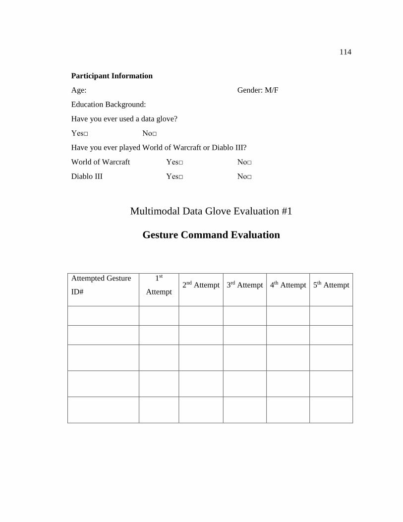
114
Participant Information
Age: Gender: M/F
Education Background:
Have you ever used a data glove?
Yes□ No□
Have you ever played World of Warcraft or Diablo III?
World of Warcraft Yes□ No□
Diablo III Yes□ No□
Multimodal Data Glove Evaluation #1
Gesture Command Evaluation
Attempted Gesture
ID#
1st
Attempt 2nd Attempt 3rd Attempt 4th Attempt 5th Attempt
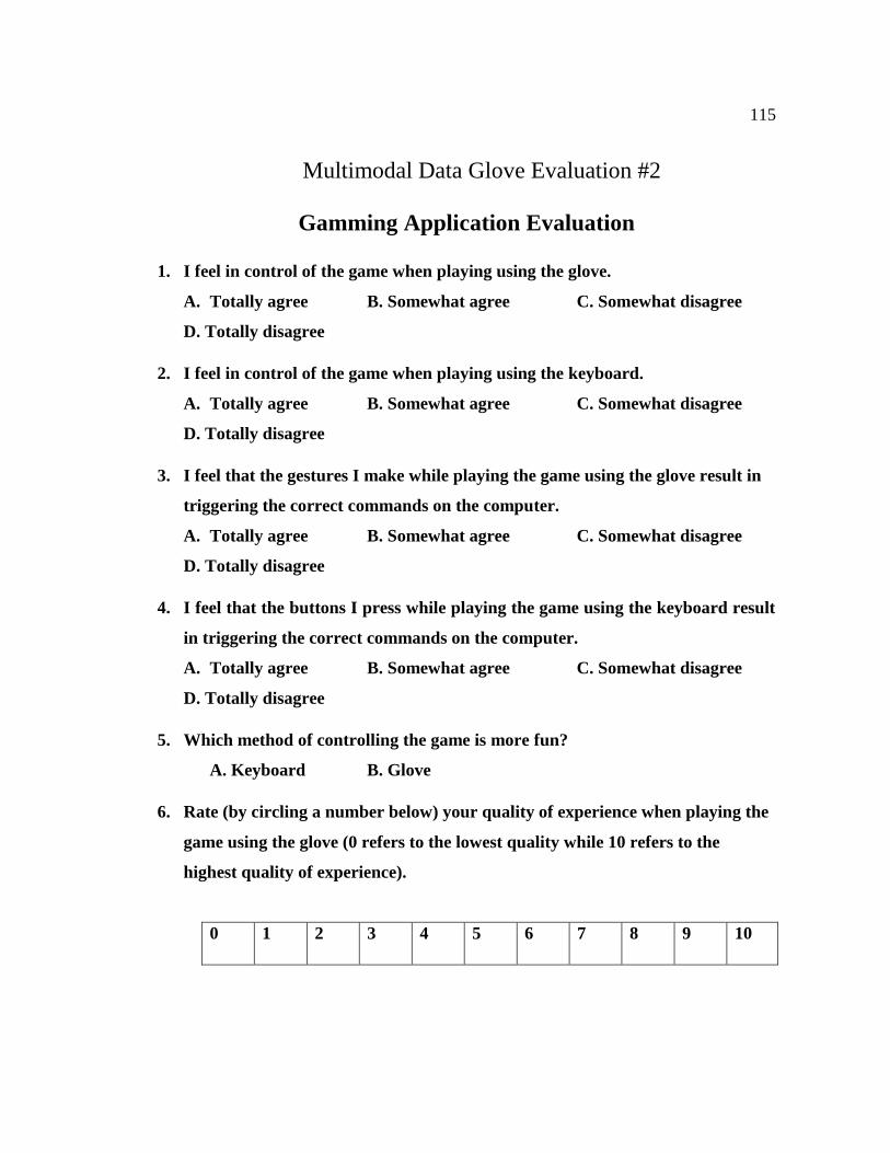
115
Multimodal Data Glove Evaluation #2
Gamming Application Evaluation
1. I feel in control of the game when playing using the glove.
A. Totally agree B. Somewhat agree C. Somewhat disagree
D. Totally disagree
2. I feel in control of the game when playing using the keyboard.
A. Totally agree B. Somewhat agree C. Somewhat disagree
D. Totally disagree
3. I feel that the gestures I make while playing the game using the glove result in
triggering the correct commands on the computer.
A. Totally agree B. Somewhat agree C. Somewhat disagree
D. Totally disagree
4. I feel that the buttons I press while playing the game using the keyboard result
in triggering the correct commands on the computer.
A. Totally agree B. Somewhat agree C. Somewhat disagree
D. Totally disagree
5. Which method of controlling the game is more fun?
A. Keyboard B. Glove
6. Rate (by circling a number below) your quality of experience when playing the
game using the glove (0 refers to the lowest quality while 10 refers to the
highest quality of experience).
0 1 2 3 4 5 6 7 8 9 10
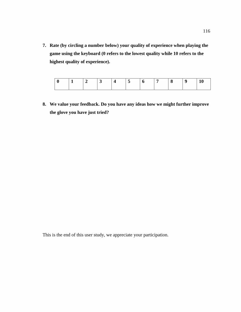
116
7. Rate (by circling a number below) your quality of experience when playing the
game using the keyboard (0 refers to the lowest quality while 10 refers to the
highest quality of experience).
0 1 2 3 4 5 6 7 8 9 10
8. We value your feedback. Do you have any ideas how we might further improve
the glove you have just tried?
This is the end of this user study, we appreciate your participation.