The Linear Collider Alignment and Survey (LiCAS) Project Richard Bingham*, Edward Botcherby*, Paul...
15
The Linear Collider Alignment and Survey (LiCAS) Project Richard Bingham*, Edward Botcherby*, Paul Coe*, Grzegorz Grzelak*, Ankush Mitra *, Johannes Prenting, Armin Reichold* *LiCAS Group, Particle Physics sub-department, University of Oxford, Applied Geodesy Group, DESY, Germany
-
date post
20-Dec-2015 -
Category
Documents
-
view
218 -
download
2
Transcript of The Linear Collider Alignment and Survey (LiCAS) Project Richard Bingham*, Edward Botcherby*, Paul...
The Linear Collider Alignment and Survey (LiCAS) ProjectRichard Bingham*, Edward Botcherby*, Paul Coe*,
Grzegorz Grzelak*, Ankush Mitra*, Johannes Prenting, Armin Reichold*
*LiCAS Group, Particle Physics sub-department, University of Oxford, UKApplied Geodesy Group, DESY, Germany

14 November 2002 The Linear Collider Alignment and Survey (LiCAS) Project 2
Contents
• Introduction
• LiCAS Project Overview
• Description of Measurement System
• Summary

14 November 2002 The Linear Collider Alignment and Survey (LiCAS) Project 3
Introduction
• Next generation of Linear Colliders will require precision alignment
(eg:- TESLA: 33km Tunnel, Alignment: 200m over 600m)
• The problem– Current open air survey techniques are not sufficient– Ground motion will bring accelerator out of alignment
• Solution: Proposed DESY survey train
with LiCAS : A novel optical system

14 November 2002 The Linear Collider Alignment and Survey (LiCAS) Project 4
Accelerator Alignment
Accelerator Component
Tunnel Wall
Reference Markers
• Place reference markers along tunnel wall • Measure accelerator component with respect to reference markers
How are the reference marker positions measured ?
Tunnel Rail
Use a survey train
14 November 2002 The Linear Collider Alignment and Survey (LiCAS) Project 5
LiCAS Project
Internal Measurement System (FSI+SM) inside a vacuum pipe
Tunnel Wall
Tunnel Rail
External Measurement System (FSI)
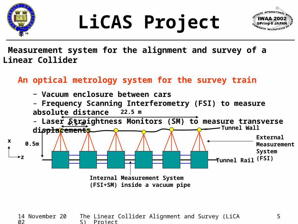
Measurement system for the alignment and survey of a Linear Collider
An optical metrology system for the survey train
− Vacuum enclosure between cars– Frequency Scanning Interferometry (FSI) to measure absolute distance – Laser Straightness Monitors (SM) to measure transverse displacements
4.5 m
22.5 m
0.5m
z
x

14 November 2002 The Linear Collider Alignment and Survey (LiCAS) Project 6
Survey Train in ActionTunnel Wall
Tunnel Rail
Internal FSI Lines and SMReference Wall Markers External FSI Lines
Reconstructed Tunnel Shape
14 November 2002 The Linear Collider Alignment and Survey (LiCAS) Project 7
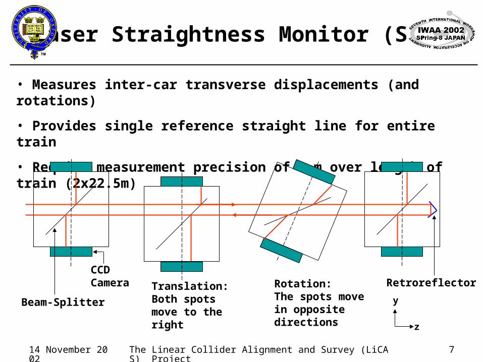
Laser Straightness Monitor (SM)
• Measures inter-car transverse displacements (and rotations)
• Provides single reference straight line for entire train
• Require measurement precision of 1m over length of train (2x22.5m)
CCD Camera Translation:
Both spots move to the right
Rotation:The spots move in opposite directions
Beam-Splitter
Retroreflector
z
y

14 November 2002 The Linear Collider Alignment and Survey (LiCAS) Project 8
SM: Two Beams
Use two parallel beams to measure rotation about z-axis
z
y
x
y CCD Image
SM beams coming out of the screen
Image of beam spots observed on CCD Camera

14 November 2002 The Linear Collider Alignment and Survey (LiCAS) Project 9
Frequency Scanning Interferometry
Tunable Laser
•Interferometric length measurement system
•Aim for measurement precision of 1m over 5m
Reference Interferometer: L
Measurement Interferometer: D
Change of phase: GLI
Ref
GLI
L
D
Change of phase: Ref
time
IRef
time
IGLI(Grid Line Interferometer (GLI))

14 November 2002 The Linear Collider Alignment and Survey (LiCAS) Project 10
FSI in LiCAS
Delivery Fibre
Return Fibre
LiCAS Collimated Quill
Fibre Splitter
fibre end
Collimation Optics
Retroreflector

14 November 2002 The Linear Collider Alignment and Survey (LiCAS) Project 11
Extensions of FSI for LiCAS
Move to Telecoms wavelength (1510 nm-1640 nm)
Exploit cheap high quality tunable lasers Reduce drift errors
– Greater continuous tuning range (130 nm)– Faster tuning rate (40 nm/sec)
Easier separation of laser signals – Use amplitude modulation
Use Erbium Doped Fibre Amplifiers (EDFA) Modular power distribution

14 November 2002 The Linear Collider Alignment and Survey (LiCAS) Project 12
LiCAS Survey Train
FSI
Laser Straightness Monitor
Rails attach to tunnel wall
Measures 3D position of accelerator wall reference markers
Vacuum tube
z
x
y
Internal FSI+SM measures train’s internal positions

14 November 2002 The Linear Collider Alignment and Survey (LiCAS) Project 13
LiCAS Survey Train: 2D
z
x
Tunnel Wall
z
y
reference markers for accelerator(Ball-mounted retroreflectors)View from above
Side on view

14 November 2002 The Linear Collider Alignment and Survey (LiCAS) Project 14
Survey Train Simulation
•Simulations of train performance using “SIMULGEO”
•Simulation includes whole system: Internal & External FSI + SM
•Studies have highlighted areas for improvements in the design
•Eg: Train sensitivity to rotation about z axis • Consider addition of tilt sensors to cars and/or 2 rows of wall markers

14 November 2002 The Linear Collider Alignment and Survey (LiCAS) Project 15
Summary
The LiCAS group has proposed an automated optical measurement system for the survey and alignment of any future Linear Collider
The current design for TESLA alignment is under development at Oxford