THE JOURN'AL OF GEAR MANUFACTURING · THE JOURN'AL OF GEAR MANUFACTURING CUT ING TOOLS C IDE...
52
TEe H o L GY THE JOURN'AL OF GEAR MANUFACTURING CUT ING TOOLS C IDE REHOBBIN~ - TECHNOLOGY HAT WORKS COMPUTERIZED HOB INSPECTION MINIMIZING BACKLASH IN SPU GARS D SIG ING SPUR GEARS FOR MIN MUM NOiSf SELECTING, AN ISO 9000 CONSULTANT - WHO, WHEN & HOW? -----~ ... -- -- -.-.-------~--~
Transcript of THE JOURN'AL OF GEAR MANUFACTURING · THE JOURN'AL OF GEAR MANUFACTURING CUT ING TOOLS C IDE...

TEe H o L G YTHE JOURN'AL OF GEAR MANUFACTURING
CUT ING TOOLSC IDE REHOBBIN~ - TECHNOLOGY HAT WORKS
COMPUTERIZED HOB INSPECTION
MINIMIZING BACKLASH IN SPU GARS
D SIG ING SPUR GEARS FOR MIN MUM NOiSf
SELECTING, AN ISO 9000 CONSULTANT - WHO, WHEN & HOW?
-----~ ... -- -- -.-.-------~--~

II's a Pfauten .•in stock. and availabletoday with these outstandingfeatures ...all standard!
I!f GE FANUC Series 15 CNC, withuniversal-menu programming tofully automate setup
IifFANUC Digital AC servo driveson aU 5 axes, as well asFANUCmicroprocessor-controlled hobspindle drive system
IJfWorktable with twe-start doubleworm andwerm gear drive
_ Hob head. with tangential slide.including hydro-mechanicalclamping/unclamping ofhob head swivel
IifIQuick-ch~nge hob arborclamping. including hydro-mechanical damping attachmentfor outboard bearing support
lIf SmaU footprint design .. includingattached-tank hydraulic andrecirculating lube system
':if Built and supported by AmericanPfauter, conveniently located inRockford, Illinois U.S.A.
-
...And much more!For the gear hohber you've alw.ays wanted,call (81S) 282-3000
,,'t
I .'~
1351 Windsor RoadLoves Park, Il61132-2698 U.S.A.
LimIted Partnership
Phone: 815'282-3000T elefax: B15-2B2-3075
CI'RCLE 1\·1 on IREADER REPLV CARD

In every type of tooth and threadcutting tool=hobs, shapercutters,form-relieved milling cutters-«we continuously apply advancingtechnology to produce better, moreproducti ve tool .
Example: OUI patented Wafer"Shapet Cutters with disposable blades.Example: Our high-speedthrow-awayWafer'" Hobs ..'Io see theseand other leading-edgetechnologies in gear cutting tools,visit our 'Gear Technology Center.
Justphone us at (815) 877-8900Of fax us at (815) 877-0264for arrangements,Pfauter~Maag ,CuttingTools135 J Wmdsor RoadLoves Park. Il,61111
Innovative tools for gear cuttingand form milling applications
Pfauter-Msag Cutting ToolsUrnited Partnership
CIRCLE 0\-2 011 R'EADER REPLY OARD'
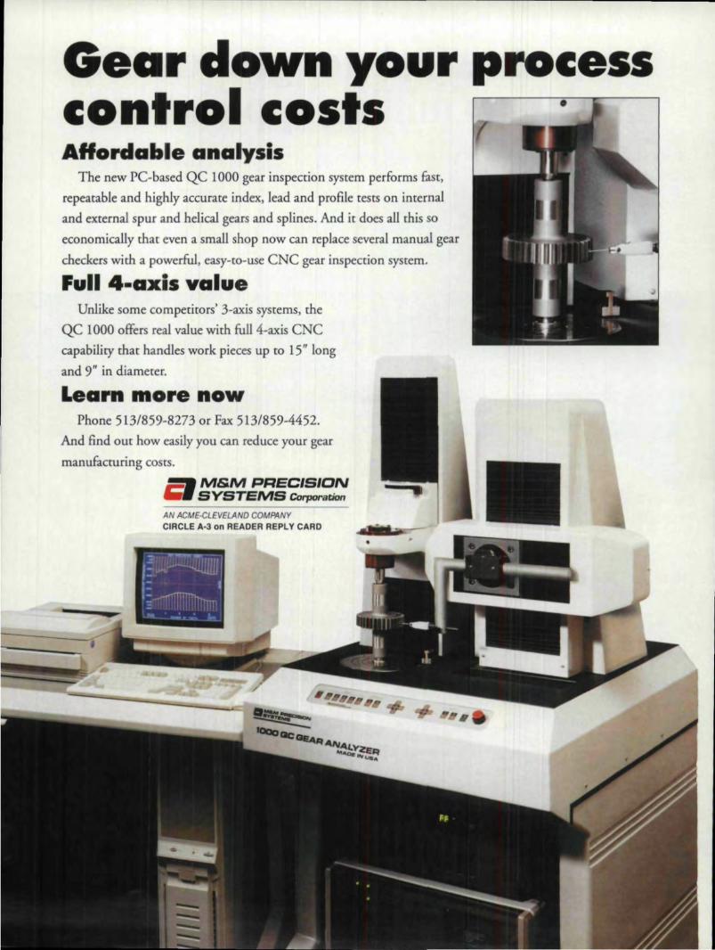
Gear do~~nyour processcontrol costs ·AHordable a'nalysis
The new PC-based QC '1000 gear inspection system performs fast,repeatable and highly accurate index, lead and profile tests on internaland external spur and helical gears and splines. And. it does all this soeconomically that even a small shop' now can replace several manual gearcheckers with a powerful, easy-to-use eNC gear inspection system.
',u'lil 4-axis valuUnlike some competitors' 3-axis systems, the
QC 1000 offers real value with full 4-axis eNCca.pahility mat handles work pieces up to 15" longand 9,11 in diameter.
ILearn .. o'r,e nowPhone 51.3/85,9-8273 or Fax 51.3/859-4452.
And find out how easily you can reduce your gearmanufacruring costs.
M&M PAECISIt::JNSYST:EMS Cor-poration
AN ACME-CLEVELAND COMPANYCIRCUE A-3, on READER RE.PLY CA.RD
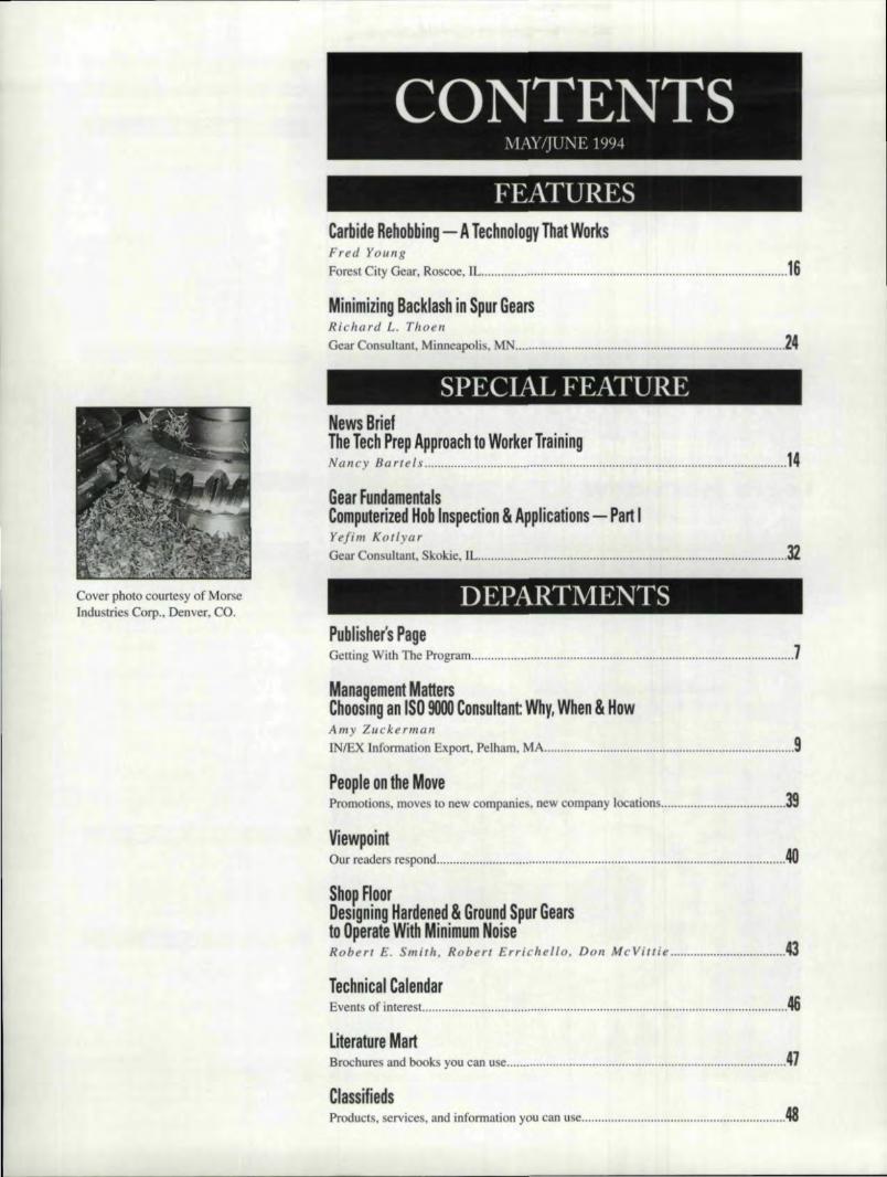
FEATURESCarbide R:ehobbing - A lechnology That WorksFred Youn.gForest City Gear, Roscoe, lL 16
Minimiz;ing Backlash in Spur GearsRicliard L. ThoenGear Con ultant, Minneapoli , MN 24
SPECIAL FEATURENews,lBriefThe 'Tech Pr,eip A:ppmach tiD' Worker TrainiinglNancy Bartels ., 14
Gear Fundamentals,Computerized Hob Inspec'ion 5. App'licat1ions - Pan IYefi m Kot Iy arGear Consultant. Skokie, n.. , :32
DEPARTMENTSCover photo courtesy of MorseIndustries COlJil.• Denver, CO.
Pub'lisher's IPa.geGetting With The Program 7'
M'anagement Matters .' ,ChOOSing an IISO 90001Consultant: Why, When '& HowAmy ZuckermanJNtEX lnformation Export, Pelham, MA ., 9
Peop'le on tbe MovePromotions, moves to new companies, new company locations 39
Viewlloint .Our readers respond , , 40
ShOp,IFl.oOf _D'esl~gmng Hardened 5. Ground Spur' Gears,to Operate With IMinimlim Noise _Robert E. Smith. Robert Errichell o, Don McViuie G
Technicall CalendarEvents of interest. , , , 46
!Literature MartBrochures and book you 'can use 4l'
ICllassiliedsProducts, services, and information you can use 48

I 1I111'1;IIT,\Sm,n
bridles .. buckles * horsehair
bits .. books * belts .. bolo
chap * spurs * saddles
!PPIWSALS
9929 Venice Blvd:Los Angeles, CA 90034
enm 202"'UOlO B1' APPOINTMENTrAJ (310) 202-(:1.10
,'* weslem coilee/ables*
CIRCLE A·4 0]11 RIEADER REPLY CARD
CIRCLE A-5 on RE.ADER REPLV CA'RO
,4 GEAR TECHNOLOGY
GEAR TECHNOLOGY
--------
FI)ITOIU.\L I
Publisher & Edi.tor-in-CbiefM]chael Goldstein
A ociare Publisher ,& Managing EditorPeg Short
Senior Editor Nany Bartels
Technical EditorsRobert EIi.ricbeUo
William L.JanninckDon McVUtie
Robert E. Smith-
\ In-Art Director Jean Bartz
An D.ireclorJennifer Golantl
Speciality typeface byUDeslgo. mcolipor,ated
,\I)\'UHIS[:'\{;
Advertising Sales Man!lgerPatrkj Flam
Circulation CoordinatorDeborah Dorngian
R.\:'\D.\I.I I'l 'Bl.ISI [1:\'(; ST.\FF
President lichaell Goldstein
Vice Pre idenl .Richard 'Goldste.in
Vice President/Genera.1 ManagerPeg Shod
Controller Patrick Nash
Accounting Laura Klirmane
Art Consultant Marsha Goldst.ein
R.\:'\']).\1.1. III 'BI.ISIII:'\:C,I:'\<..'.
]425 Lunt AvenueP,O. Box 1426
:Elk Grove Village. IL 60007(70H) 437·6604
\'01.. 1L :'\O ..~--- - - -- - - -------
GEAR TEC1OIiOLOGY, n. J .. maI aI G.... ManU!KlurI,,!!(ISSN 014]-bI!~KI i. publ"hod b,m<>nlhly by Rondall Publ .. h oS.I~_. 14lS !LYI'IIAvc:nue'", PO. BO:l 1426. E~k Omve: vm.le:. JL6(0)1. Sobocnplioo .. 1n aro: soo.oo in Il1o .s.: sso.OO in Camda;lliJJO InIJI .. horcoo....... -..etas. ....... paid OJ ...,1_He.i&ftu~ IL" lind 11 1dd11i0lUi1M1illitlg om~. Rmdall PUbillthlqmlk.8!! CiIr'C!I'J dfun CO c::m.un: thal Illfl precesses desaibal m GEARTECHNOLOGY conform to 50und I!nginftnng precaice. Neither theauthors nOTthe publisher een be held re.sponililbt~ for ."j'ilI,nell"""'""'" ...hrle r!>llow'"lih< prooedu= deKnbod.Poo""",,,,,, SMd od<Ir<u dung<> 10 GEAR ThCHNOI..OO Y. TheJoomllL .or ('.ear ManufocrllflnJ. 142:5 Lurn Avenue.. P.o. BDJl: 1426.Ell Om•• VIII!!JI<,IL, ilQIlO7,oeoo.:"" """yriahIod by RANDALL PUBLISHING, IN ., 19Q.!Anid .. _ in GEAR n;:cfINOLOGY may DOl be "'~in..- or in port _ w."......,.,.......,.. allhe puhlWler orIl10_

LOSSE5. ••

Our enchmark Qualil, Can SolveYour Gea,rmaking Problems.1 Crown hobbing for noise r,eduction andI misalignment compensation.
s • Hard hobbing with carbide hobs after~ heat treat as a substitute for gear grinding.i •(NC hobbing and shaping alignmentt5 programs for varying teeth and pitches..~ • Hobbing 2 tooth & greater heliml pinions.II:g,, • Spetial forms: flexible couplings or
~rtI ...
~ high helix worms and camshafts. =-=~ • Other servkes: precision analyticall Af inspedion and hob sharpening. •
fOREST CITY GEAR11715 Main Street • IP., O. Box 80Roscoe, Illinois 61073-0080815·623·2168 • Fax 815-623-662,0
~.L..----=. (_om_,e__se_e_u_s._I_.'_s_h_ke_la~lm_in_ia_tu_re!~ar_e~p_,o_5_it~ioa~-.~----'":"I~~~~L"
We want,oul to (Ornesee forest City Gear for y,ourself.We'r,e the most modern fine and medium pitch ,georjob shop
in the world. We especioUy we!lcome our compe'lit,o;r,s!
We/lrle!sure tho,t once you do,vou'll oQireethafwe are the benchmark fortoday's quality Igearma~king,
CIRCLE A·18 'on R~AOE'R: 'REPLY CARD

Getting With The Program
fa e.tting an..d. keeping a work force c.a•.pabl.e.ofmeeting the demands of the 21 st century isaile of the key challenge, most U.S ..manu-facturers face today. That's not even news
anymore. I - and others - have been talkingabout it ill editorials and speeches for ten yearsnow. It's also not news that the job is a tough oneand that industry-wide response often has not beenparticularly effective,
But this is not a call to despair. It has taken time,but now some exciting responses are in the works.At the AOMA Annual Meeting this year, one par-ticularly creative approach was outlined.
An organization called the National Tech PrepNetwork is addressing the challenge of creating awork force for the next century. The Tech Prep ideais a simple one: Employers and schools must worktogether to change the way we educate most of DUf
students today.The goa] of Tech Prep is nothing less than
changing the way Americans think and act abouttraining people for jobs. We've always known thatmanufacturing jobs were not "dead ends" Of just for"losers." Tech Prep wants to prove that to the peo-ple who will fill those jobs in the coming years, thestudents of today, and to those responsible for get-ting them started in the right direction, their teach-ers. parents and potential employers.
It's difficult to describe a typical "Tech Prep"program, becan e one of the beauties of the systemis that each group that buys into the idea develops itin ways !hat meet its own particular needs.
For example. not tDO far from OUi editorialoffices. over in northwestern Illinois, a groupincluding local high schools, the regional commu-nity college and six. area companies (including amajor gear tool manufacturer) have established aTech Prep Youth Apprenticeship Program. Theprogram is a combination of rigorous academicstudy, on-the-job training, mentoring and counsel-ing designed to provide students with "real world"experience and the necessary background to filljobs in the high tech workplace.
It's important to note that the "school" part ofthis program is not a "remedial" one. Students getfirst-rate training that prepares them to work in themore demanding work environment of today.
Employers who contribute get the kind of trainedforce they desperately need. It's a win/win cenariofor all concerned. (See page [4 for more informa-tion on Tech Prep.)
Of course, a program like Tech Prep requires anenormous commitment on the part of all involved.Educators have to be willing to make curriculumand program changes to meet the requirements ofthe industry sponsors. Students have to be commit-ted to a lot of hard work to succeed in the program,Participating companies have to devote time. per-sonnel, equipment" space and money to make thesystem work.
A tall order? Nodoubt. But talking topeople involved in thisexperiment convincesme that this programand others like it have agood chance for success.Tech Prep isa realisticand effective response to
a problem that needsaddressing now. Somegear companies are al-ready ex ploringtheseprograms. The rest shouldfollow suit.
Training a work forcefor tbe next centuryrequires rethinkingcher-Ishee assumptions" read-justi ng attitudes, andputting our time. money, capital and humanresources where our mouths are. The trained workforce we need is not. going to ani ve on ourdoorsteps gift-wrapped;. weare going to have to goout and get it. We as employers holda key piece ofthe trained work force puzzle - the specific knowl-edge of the kinds of skills we need and the ability toinfluence schools to provide it Without our contri-bution through programs like Tech Prep. we remainpart of !he problem, not part of the solution.
!haL.d~-~ Goldstein,Editor-in-Chief
PUBLISHER'S PAIGE- ----
IoIAY/JU'NE'1994 '1

UALITYFORTUNE!
ISO 9000 MADE EASY:A SELF-HELP 'GUIDE TO CERTIFICATION
HELPS YOU. '••,/ Save thousands of dollars in consulting fee by treamlining the certification
process;
,/ Identify "danger zones" in the process that cost your company precious timeand money;
.I Better organize In-house ISO 9000 documentation for additional savings;
./ Learn more about European ISO 9000 developments that will affect yourcompany and your pocketbook.
Tbe 1994 ANNUAL ISO 9000 ~ade Easy: A Self-Help Guide to CertificationHelps you streamlme the proce s for BIG SAVINGS!
Full of useful cost-saving tips, the fun package including Certification;. Arlditing and SeI'ec.ting a Consllltont, is availableto readers of Gear Technology at a 1.5% discount for 11 total of $58.20, plus a $5.00 h:mcUilrlgcharge. Individual bookletare $2.4.95 each. U.S. postage included. Rush order extra. Bulk: rates available,
_ Yes! Send me the full ISO 9000 MADE EASY package at $58.20, or end me my individual booklet(s) at $24.95 each:
Certification 1:11Auditing Selecting a Consultant
Be sure to include your check or money order.
Name TitIe _
Company ___
Address _
City State Zip ~~ _Include this order form and make checks or money orders payable to [Nt. X [n'forma:lioll Export, 120 Amherst Road,Pelham, MA 0]002. For more information call (4]3) 256-1949 or FAX (413) 256-4250.

Choosing AnI,SO '910001 Conslul'tanlt::Why, When & How
Amy Zuc'kerman
m ne of the key ques-tions confrontingany company con-
I sidering tso 9000certification is, how milchis thls going to cost? Theup-front fee are onlythebeginning. Dis ect the ISO9000 certification proce-dure with an eye for hid-den costs, and two seg-ments of the process willleap out - the cost of con-sulrants and Hile cost ofmaking in-house improve-ments for the ake of pass-ing certification, Most ofof the e costs can be con-Ironed by careful selectionof the right consultant inthe first place.
Because there is no reg-ulating body in the UnitedStale etting rates for con-sulting fees, those fees willvary. The lack of regula-
is no erganszation to fallback upon when and if thedecision is made to hire aconsultant, The AmericanSociety for Quality Con-trol wi II release a list ofconsultants who work inthe qual ity field. Butunlike the British NationalRegistration Scheme, theASQC does not screenconsultants or offer certifi-eation to those who meetwtsstandards.
The lack of similar reg-ulation and tandards inthe U.S. bothers officialsof tile U.S. RegistrarAccreditation Board. TheAmerican RAB, based :inWisconsin, advises U.S.companies 'thinking of hir-ing at COil ultant to learn asmuch about potential. con-
MANf\GEMENT MATTERS----- -
es .. Get references fromcompanies that have em-ployed them in the pastand check: for their e peri-ence outside of ISO 9000.
Do ~ Hu.ve To, Hire ACensultant At AU?
Can you avoid hiring aconsultant? The answerdepends en your company.its makeup and the circum-stances surrounding yourdecision to eek [SO 9000
iM.analging a businesstoday is halrd wOlrk.Let "'Management Mat-ters' lend a ha.nd.. TeUus wh-t -- - , .•__ _,a_ managemen'l.matters iinterest yID'U.
Wrlite to us at P. O.IBox14.26,. EI'k Grav,e,. IL60009. or call our sta.Hat '(70B.~437-!6604 ..
sultants as they can ahead certificatinn. Many largecorporations have suffi-cient staff level to free upseveral employees, sendthem to seminars on ISO9000 certification and workthrough the implements-
wauldt.ion process on their own.Small and mid-size compa- Amv Zuckerman
i.' co-principal ill iN/EXInfomlalion Export, amarketing consulting finnin Pelham. MA. She is theauthor aflSO 9000 Madel2asy: A Self-Help Guide10 Certification.
"' ....VIJUNE 1884 9
nies may not have thisoption and may very wellneed orne assi lance froma qualified expert
And how does one go
to "II'ClIIIlaIlll8Ir1.

about de1!.ennining who is a
qualified expert or decidingwhether his/her servicesare necessary?
Before making thi aU-important deci ion. It'scrucial to under land howquality ISO 9000 consul-tants can operate to assistyou, There is no single wayor method CO.11 ultaotsshould adopt, nor can theyassist every company in theexact same way. But itispossible to determine whena eonsuhant i takingadvantage of you throughover-advising and increas-ing the workload or byunder-advising or neglect-ing your concerns.Wha.t Can A Consultant
Do For Me?Con ultams should act as
facilitators of an in-companyprocess and encourageclients to help themselvesas much as possible. Agood consultant will notattempt to take over the
make sense for the cornea-ny's long-term operation,not to simply pass ISO9000 certification.
A good [SO 9000 COI]-
sultant will constantlyemphasize that 'CJluaHtyemanates from within .. notfrom the consultant. Thecompany must. create itsown quality procedureswhile the consultant callmerely guide the process,For this reason. be wary ofconsultant trying to over-sen the certiflcationpro-cess. Like any honestsalesperson. a good ISO9000 consultant shouldwant to truly assist a client.not push to earn an unwar-ranted fee.
Here are orne ways youcail best utilize a consul-tant's service :
'v Consultants may bebrought in-house to assesswhether a company is anappropriate candidate forISO 9000 eertificarion and
total. pre-certification pro- how well thi companycess to earn higher fees, A would perform against. ISOquality consultant willreal- 9000 q-uality . tandards.ize that quality standards V A good consultantand procedures must be can translate the differencegenerated from within theorganization and become aworking part of it.
Consultants can help etdirection, determine whichform of WSOcertification 1.0
pursue. provide guidance,encouragement and struc-ture. B IUt it's lip to eachcompany to design its ownprocedures, determine howto implement quality stan-dard and then continue tolive up to those standardsduring the post-audit andpost-certification years ..Thee standards should
10 GEAR TECHNOLOGY
between your current. quali-ty system and the [SO 9000standards - should therebe one - into an actionplan of item 10 be accom-plished before the real [SO9000 registrar is brought infor the certification audit.
ttl The consultant canwork together with compa-ny personnel 011 imple-men ling the action plan.This may mean trainingpersonnel. to maintain newquality standard, estab-lishing new operating pro-cedures, advising on equip-
ment purchase . recalibra-tion of measuring equip-ment or any other changethat. will bring tile opera-tion lip to acceptable levelsunder ISO 9000.
.......A consultant may setUp3 check. -and-balancessystem withill the organiza-tion. thu allowing em-ployees to monitor qualityfrom within,
V The consultant mayassist trnecompany inapplying to the RAB forcertification and in hiring aregistrar to conduct the cer-tification audit
'v Some con ultantswill act as an "internal"
diture? Be wary of consul-tant . pre uring you to
seek certification regard-less of your circumstances.Instead. like any goodadvi or, a quality ISO 9000'consultant should assistyou to oft OIH an appropri-ate direction.
The kind of questionshe/she should pose to in-sure that ISO 9000 certifi-cation is .appropriate foryour company appear in thesidebar on the next page.
What Happens Next?If a consultant, upon
posing the. e questions,finds that a company isoperating at top ]SQ 9000
I
MANAGEMENT MATTERSI
Hyear company •
ISO 90lIOlevels, YOBr consultanthould anca 1ft rly
inspector, conducting a pre-audit to insure that all nee-essary changes have beenimplemented and that theoperation will pass its IS'O9000 certification.
The absolute first stepany consultant should takeshould be to assess whethercertification is necessary oreven desirable for a. partic-ular company. Companiesshould be advi ed to look:at IS'O 9000 like anyinvestment: How much canyou afford to pay, and will.the ends warrant the expen-
levels. he or she shouldencourage the company toseek an early audit andbow out of the process.TIle COil. ultant should alsobow out if he or she dis-cover that an alternateform of certification wouldbe preferable to ISO 9000.
To conduct an audit .. theconsultant must conduct'interview with crucialmem'bers ofthe company'staff. A good rule of tbumbIor determining the timeneeded for this preliminaryprocess is to divide the
n.eIS09000y __ a••• ala .....
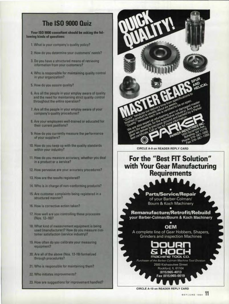
lowtag IdIIdI of qu.~
1.What is your company's quality policy?
2. How do you determine your custDm8rl' needlT
3. Do you heve a structured mHns at retrievinginformation from your customers?
4. Who is responsible far maillltainfng qullity controlin your orgamzatlon?
5. How do you assure qua4ity?
6. Are all the people In your employ aWirt of qualityand the need for maintaintng strict qUIU~ controlthroughout the entire operation?
7. Are all 1ft. people in your amptoy aware of yourcompany's quality procedures?
8. Are your emptoyHs wtll-traintd Dt' edltoaI8dfartheir cunlAt poIltions?
9. How do you curramty measure1M .... fof1MftHof your suppliers?
10. How do you keep up with the quality &KIenftwithin your industry?
11. How do you m818Ur8 accuracy, wMlher you de..in a product CII' a .. me.?
12. How pervasive art your accuracy proceduras?
13. How are the results regilt8red?
14. Who is In charge of non-confomUng products?
15.AnI customer complaints being regiltend in astruetured manner?
16. How is correctiVe action taken?
17. How well are you controlling ttl... proC8S888(Nol. 12-18"
18. Whet kind of m8l8unml8llt &fIuip ..used (manufael1trert? Haw drtyau ....tamar lI1isfaerion t.rvice irldUmvJf
19. How often do you oellbrata your mehUJ'IRgequ,pIMRt'l
20 Are all of1he above (Nos 12-lItfenQf"through precldura?
21. Who 18reaponSlble for maIntaining .em?
22. Who initiates improvements?
23. How are suggestions for improvement Ilandled?
~ -I
CIRCLE A-9 on IREADER IREPLY CARD
IFor the .lIiBest F;IT',Solutiion"with Your' 'Gear' Man!Ufa,cturilng
Requilrements
CIRCLE A-l0 'on READE,R'REPLY CARD
MAY/JUNE 1994 111

hiring him on for addition-al hour . The owner choseto hire the consultant toassi t with changes in hisquality manual on a one-time basis. Cost avings incon uhing hour wereinsured by this approach,
The machine shop own-er did recognize, however.that the cOnSUlla11t was ableto speed up the certifica-tion process by acting as apre-auditor and by servingas anadvisor in the cre-ation of the ISO 9000 com-pany implementation planrequired for certification.
The Final AnaJysisTo hire or not '10 hire an
outside con ultant to helpyou with ,ISO 9000 deci-sion-making remains thequestion. The answer mustbe based on an honest
number of employees bysix (for six interviews aday). So it would takeabout. four days recorn-plete an audit wi th a com-pany of 24 employees.
The con ultant mustthen draw up a report offindings, which would addanother six or so hours tothe 24 already spe.nt withthe cl ient. This reportshould include a list of
as an occasional advisor.A Case In Point
A Massachusetts precl-sion machine companywith 35 employee is agood example 0;1' how aconsultant can and shouldhelp a company throughthe ISO 9000 process. Aconsultant was brought intoassess this company's qual-ity levels and determinedthat the shop was operating
I.
assessment of your compa-ny's capabilities. Do youhave the time and resourceto go it alone?
Once you have made adeeisicnto seek outsidehelpcevahiate potentialcandidates for the job withthe same care you gi ve toany other vendor. Ask forreferences and recommen-dations. Don't be snowedby ISO 9000' hype. Scruti-nize proposals with care.Ask whether a particularpart of the process is reallynecessary in your circum-stances. Look for the con-sultant. who is interested inhelping you achieve your[SO 9000 goals, ratherthan in just making a bigprofit. Investment in sucha consultant can be moneywell spent. I.
-
MANAGEMENT MKfTERSat dose to ISO 9000 levels.To pass certification, how-ever, this company wasadvised to better documentits quality procedures .. Thecunsultant in questionoffered the shop owner thechoice of appointing am in-mou e [S0' 9000expe.rt -thus going it alone - or
actions required for thecompany to meet ISO 9000'standards. At this point theconsultant ha workedabout 30 hours. Dependingon the client' needs andstaff levels, a con ultantcan be maintained in-housefor the duration of the cer-tification prnce or to act
PfRf [L fHPf SL ~UI IWHEN YOU NEED IINTIRltATE DESIGNIS ANDI METICULOUS CRAFTSMANSHliP. RELY ON FA!IRLANE GEAR, I'NC.
WE. OFFER:• Gear Noise Reduction Program• Expert Technical Assistance.•Gear Cutting in a Wide Range
of Sizes, Types & IQuantities• Prototype & Emergency Re-
pair I Rebuild Service
COMM'II1TMENT TO nUALIfYReishauer Ground GearsM & M Precision GearCheckerKapp CBN Hard FinishedGearsAmerican Pfauter eNC HobCoordInate Measurement
Machine
NEW MACHINES JUST PURCHASED.... KAPP tNC HARD FINISHER.... AMERICAN PFAUTER CNC HOB
Gualitygears upto AGM'A.115, Mlll-1·4520BA, MIL-STO-45662
FuliV implemented SPC, and datacommunications capabilities.
SIZE RANIGIE -Srneller than aninch to 48'
For the' ultimate in qua.lity '9;ear5,call or send inquiries to:
TYPES:Spur - Internal & ExternalHelical- Internal & ExternalWarms, Worm GearsSerrations - ShaftsSplines- Internal & ExtermalSprockets - ClustlersSegments - SpindlesRatchets - Gear Boxes
Fairlane Gear.llnc.
P. O. Box 409 APlymouth, MI481170Phone 1313)459-2440
IBOO) 837-1773Fax (313)'459-2941
CIRCL'E A·1,1 0.", READER REPLV 'CARD
12 GEAR TECHNO~OGY

D'ORINE~~~~/HOWrrrrTO ITART
Il YO'U'RIWA.ITIMG FO'R THI OPIMIM'C:or lM.TI TOGil TBI AIII"IIOM or YOUR C.U"OJ4.IWIt
')"OU'LI. BILIFl' BIHIND.
• 50 to 70% of IMTS visitors are ready to buy when they get there. *
• More than 76% of them come armed with a list ofmust-see products and services."'*
Advertising in Gear Technology's Pre-Show and Show is ueswin reinforce your IMTS efforts with:
'. ADDED BONUS DISTRIBUTION• Extra overseas distributlon of Pre-Show issue
• Extra distribution at IMTS
DON'T WAIT FOR THI e.URTAIN TO,GO UP •.GIT IHI 411IMTI'OM ,or THEIM:TI 4UDIINCE
WITH 4D/IM 'G14R: TIC.HMOLOG"Y.
CALL 1...800 ...45.1...8·166TOD.~
*Accurding to Jacobs, Jenner & Kent. market research firm .
....lncomm International market research.
14 GEAR TECHNOLOGY
---------------------------------------------------
The Tech Prep Approachto Worker Training
Industry and Education Combine' Forces to Close the Training Gap.
Nancy IBane~ls
EIo.re than b~lf all.r young pe.oPle lea".eschool without the knowledge orfoundation required to find and holda job."according to a 1991 report
from the U.S. Dept. of Labor .. A huge gape i ts between the need of employers (espe-cially in manufacturing) and the trainingreceived by most high school students.
This is not good news for employers. espe-cially in the manufacturing sector, for theirmanagers who need killed workers to keeptheir departments running at peak efficiency,or for the high school graduates who find thai.their diplomas have not preparedthem to earna decent living. However. just in the last fewyears, more than a half a million young peopleand the employer and managers for whomthey work have found a bridge aero thitraining gap with the help ofa program calledTech Prep.
The Tech Prep IdeaThe idea behind the program is a simple
one: Employers and schools must work: togeth-er 1.0 change the way we educate most of ourstudents today, Eighty percent of the jobs inthis country do not require a college degree.but. they do require orne kind of advanced tri-anlng: however. at present, students in "gener-al." curricula. (those not bound for college) arenot trained for any ofthese jobs. The goal ofpresent. high scheol program s.eems to be toqualify students for a diploma, not to train awork force.
Tech Prep addre ses Ihi issue through thedemocratic notion of "grass roots" efforts onthe part of the people involved - in thi caseeducators, employers, students and parent .. InTech Prep. local employer discuss their par-ticular training needs with the high schools andcommunity colleges in their area andthendevelop a program to rneet those need ..
One such program is now in the works innorth central IIIi'l1O.is. There, Rock Valley Col-lege, several Rockford area high schools andsix local employers (including a gear tool man-ufacturer) have combined their resources tostart a Youth Apprentice hip Program. Thisprogram recruits students after their tenthgrade year and places them in an intensivework/study program that combines a rigor-ous academic SChedule with on-the-job train-ing at the facilities of one of the ix sponsoringcompanies. The program carries studentsthrough their high chool year. and continueas they pur ue tudie at Rock Valley Collegeand into full-time apprenticeships.
Youth Apprenticeship Training ProgramThis is how .It work . The summer after
their junior year, the Rock Velley programrecruits begin full-time (40 hours a week forat lea t six weeks) work/tralning at all thesponsor sites. During their senior year. theywork four hours a day with an individualponsor while maintaining a regular academic
schedule. After graduation, qualifying stu-dents move to full-time apprentice hip . withcredit being given for their Youth Apprentice-ship hours ..They also have the option of con-tinuing their education toward an associate'sdegree (or a baccalaureate) while working asfull-time apprentices.
Students in the program get paid for thework they do while learning. They a1 0 explorethe variety of opportunities available in manu-faeturingand acquire skills essential in theworkplace now. At the same time, employersget a supply of skilled, capable employees,trained for pre ent job in their factories andready to take 0.11 new challenge .
The Basic IngredientsOther program in other places are tailored
to the p,articular needs of their developers, but

whatever the externals. each one incorporatesthe following characteristics:
•. Contextual leaming. The empha is is onapplied academics - how math, science andcommuaication skill are usable in "real world"settings.' ontent i academically rigorous, butalso connected to actual workplace experi-ence . The principle of productivity, team-work. and flexibility that are 0 important tothe modern workplace are also emphasized.
• Local Partnership . Employers. labor andcommuniry leaders. parents and educator areall part of the planning and implementation oflocal programs. Bread-be ed local . upport ie entia] to the sucee s of Tech Prep programs.
• Career exploration and counseling . One ofthe goal of Tech Prep programs is to help tu-dents to make intelligent career choices andexplore options that best suit their aptitudes.
• Advanced degree potential. Fouedationalskill are solid enoughto prepare srudent foreither associate or baccalaureate degrees ifthey wish.
.•.A "bridge" program. Participating groupshave also developed a variety of internship andother work/ tudy and "bridge" programsaddressed [0 tile needs of older workers whohave already left school and may need someacademic "refre her" courses to ucceed in tileadvanced a oeiate degree program requiredto upgrade 1:lleir. kill .
Flexibiility and OptionsOne of the virtues of the Tech Prep programit versatility. Programs are developed by the
people who will u e them toaddresstheir spe-cific needs. All the programs begin with exten-sive conversations between local employers,educators. labor and community leaders. andstudent and parents to assess needs and plansy tern that be t. fit the requirements of partie-ular communities, Exten ive community 1.11'-port is needed in order to makethe programwork. and development of "ownership" on thepart. of all participant is crucial to programuccess. Company size Is no. deterrent to par-
ticipation. In fact. smaller companies withoutthe resources to provide elaborate training oftheir own may find a Tech Prep alliance partie-ularly useful.
Beginningshe "father" of Tech Prep :is Dale Pamell,
an educator and president of the American
Association of Community and Junior Col-I:eges. He first outlined 'the idea in hi book TheNeglected Majority. Parnell and engineer DanHuH further refined the idea of buildingalliances between high school, communitycolleges and employers. and in the late I.980sParnell established the Center for OccupationalResearch and Development (C.oRD). a non-profit organizatien with headquarters in Waco,TX. devoted to. fostering the Tech Prep idea.
The program was given more impetu by thepa age in 1990 of the Carl D. Perkins Voca-tional and Applied Technology ducation Act,which provide fund for programs addre singworker education. including Tech Prep.
]n 199], CORD organized the NationalTech Prep Network W support local Tech Prepprograms through information-sharing. net-working, conferences. publicadons. and pub-licity. The NTPNal 0 ha a data base of infer-marion on various local program and willarrange tour of model pilot programs in van-ou parts of the COUIlU'y for groups interested indeveloping their own Tech Prep programs. Acall to NTPN i frequently the first step in get-ling a local Tech Prep program off the ground,
For a $95.00 membership fee individuals inindustry and busines , education. communityorganizations and local. tate and national gov-ernment, can become part of the network andmake use of all its programs and ervice .
A Drop' In The BucketOne estimate of employment trends suggests
that by the year 2000. 15.000.000 manufactur-ing jobs will require advanced technical kills.At the same time 15,000.000 service jobs willdisappear from the economy. These numberssuggest that Tech Prep. and programs like it,have a long way to' go if they are to meet CUf-
rent and future demand for skilled labor.W.hat they are attempting is nothing less
than a reform of general high chool educationand worker training nationwide. W;hi]e theundertaking may seem visionary, itis alsoe ential if the country is to maintain it com-petitive edge in the future. It i a chance formanufacturers of all types and sizes to take apro-active stance in developing the skilledwork force they need to remain competitive. 1.1
Ca.1i the NTPN at 1-800-972-2766 for more.illformation. about Tech Prep.
Nancy Barte:lsis Gear Technology'sSenior Editor. She haswritten mllll}' articles onis II(,S a/importance 10
business and industry.
MAY/JUN.e 1 ~U'4 15

Carbide RehobbingA New Technology
That Works!Fried Young
F,orlest ICity GearRoscoe, IIIL
Many people in the gear industry haveheard of skiving, a process wherein solidcarbide or inserted carbide blade hob with15 - 600 of negative rakeare used to recutgear to 62 Rc. The topic of this article is theuse of neutral (zero) rake elid carbide bobsto remove heat treat distortion, achievingaccuracies of AGMA 8 to AGMA 14. DIN10-5 and improving urface finish on gearsfrom 8 DP - 96DP (.3 module - ..26 rn.),
Early technology developed with Azurniskiving hobs yielded encouraging result .However, few people seemed to adeptthisprocess in lieu of gear grinding. Among thedrawbacks were [he necessity of havingextremely rigid bobbing machines and workflxruring. expensive tooth timing, centeringdevices. expensive cutters, and the difficulty of
[p EXcept CIR, J015 MalfllPl' eIIG•• :r: .spur
I Pr..,,,ur •• nl/I.: 21"Oil m.tr.IIIP~ch: 12·Numblr 01T,Ith: 14Pia:hIDilltlllM:l.tM1 l'UJ.oolllA-B1 PJD.Mu AIlowabl. Eec,~ncl!'f.TmICo"'0Irtl' &~f .cm~t. '0 tu!" P.=B1 wch Mull.IBlckluh .IXl4 Mm• .996 PILl<WIIhlJi"'.lulMating IG.lr: PIN J02Q..I88 OD. Min. Min,
He,alTlm 14IlAmlr Dimnc., Min ..1.1_,
H.lix An;'.: R.II. or Il. H.l.1 d: NDminalMin. Rom Fitl.t IRadiLl': !D131Cll" ol'IGnt liP,,, SS·I&1l: e," li I[l:>8u.' Cif,cl" !ll1Ii1!l': !l1,SIT"", InvoIyt' I'onn, lIiamWier 1T.1.1F.1: I.C6lIlInvolUlllloll' Arlgl, to T.U: Di,.: 14" ,e1"11'IY1J1llt1 RolliAngl.tD Outside Di.~~·1·Root 011.;9q5 M;n.I.o111 Mu.[)"m,rqion (lv" Pirq 1,.3569 -131mM".ur·ing Piu Oi.mltlr: .144
I
Hob blJrrthisside,
Usa d~btmIIttachmentto remeve.
UlC FROM GROUND SmE
Fijl.l- Case]
116 GE .... R TE CH NOLOGY
.765
1.'6321'(.163U
re-sharpening the cutters properly to raaintainthe correct involute.
Some of these problems have been eliminat-ed by using zero-rake solid carbide hob whichare available from ma.ny of the major hob man-ufacturers, This elim.inate the need to offsetthe diamond wheel when resharpening on ahob sharpener. reduces the initial. cost of pro-ducing the cutter and increase cutter life.Another improvement i the common use ofnon-contac], electro-magnetic sensor whichautomatically divide the stock on the toothflanks with extreme accuracy, lfthe quality ofLhegear is excellent initiaUy and heat treat di -tortion i minimal. it is possible to recut gearswith as little as .0015 - .003" over wires as asalvage method for gears which grew unex-pectedly during heat treat.
Ideally gear should be roughed with protu-berance hobs which have any desired profilemodification built in, If the part i, crowned, itmay be beneficial to crown during roughing 0
that an even amount of lock: is removed fromthe flanks, leaving a uniform case hardnessdepth. Helical gears often unwind during healtreat, and accommodation may be made toincrease the helix angle. For fillle pitch, we startwith approximatel y 0° [5' as an offset.Remember that if a protuberance rougher isused. it generally only produces the correctinvohne in a sometimes narrow range of teeth.
Our experience is limited to the carbide
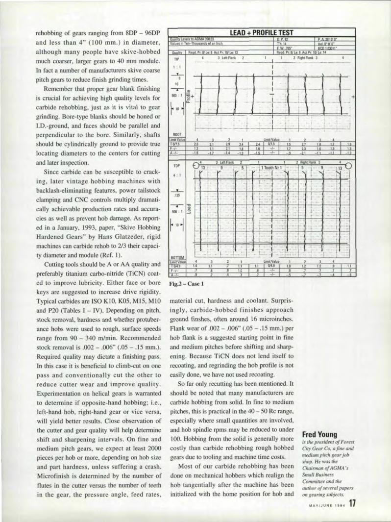
rehabbing of gears ranging from 8DP - 96DPand less than 4" 000 mID.) in diameter,although many people have skive-bobbedmuch coarser. larger gears to 40 mm module.In fact a number of manufacturers skive coarsepitch gears to reduce finish grinding times.
Remember that. proper gear blank finishingis crucial for achieving high quality levels forcarbide rehabbing. just as it is vital to geargrinding. Bore-type blanks should be honed. ortD.-ground, and faces should be parallel. andperpendicular to the bore. Similarly. shaftsshould be cylindrically ground to provide truelocating diameters to the centers for cuttingand later inspection.
Since carbide can be susceptible to crack-ing. tater vintage bobbing machines withbacklash-eliminating features, power tailstockdamping and CNC controls multiply dramati-cally achievable production rates ami accura-cies as wellas prevent. hob damage. As report-ed in a January. L993 •.paper, "Skive HobbingHardened Gears" by Hans Glatzeder, rigidmachines can carbide rehob to 2/3 their capaci-ty diameter and module (Ref. 1).
Cutting tools should be A or AA quality andpreferably titanium carbo-nitride (TiCN) coat-ed to improve lubricity. Either face 0[ borekeys are suggested to increase drive rigidity.Typical carbides are ISO KlO, K05, MIS, MIOand P20 (Tables I - IV). Depending on pitch.stock removal, hardness and whether protuber-ance halos were used to rough, surface speedsrange from 90 - 340 m/rnin. Recommendedstock removal is .002 - .006" (.05 - .15 mm.).Required quality may dictate a finishing pass.In this case it is beneficial to climb-cut on onepass and conventionally cut the other toreduce cutter wear and improve quality.Experimentation on helical gears is warrantedto determine if opposite-hand hobbing; i.e.,left-hand hob, right-hane! gear or vice versa.will yield better results. Close observation ofthe cutter and gear quality will help determineshift and sharpening intervals. On fine andmedium pitch gears, we expect at least 2000'pieces per hob or more. depending on hob sizeand part hardness. unless suffering a crash,Microfini. h is determined by the number offlutes in the cutter versus the number of teethin the gear. the pressure angle, feed rates,
Values In Tan-Tho-us:andl 0'1: In Inch
LEAD ... PIROIFILIE TESTCl'1? ,.28- Il'n"
R.qd. Pr. 8/ L.: 8 Att 1'1:101L.: 13
h. ~ --';"Il'"O'O-
F W.J"· lmill'R.od PrBlt.O:8Ac!PrTCilLe I~
3 LoftflaM. Z I I 2 RJ~h!flink 3------- ---------~.------
II
Du"lit\<TIP
I: I
~o
10 I,- ..,-I-~-' - --, --11---,'----...1\.. -, -,--
~ ! iE+ +
~ 10 ft t=t=='===f!:=.l" =-""=- =- ., 11=' -=-:;=1:' '=~-=i=:_=':!::;' -~-:::I:::=-=.~::!="
I ,'I :1 I~~~~--'~..-r---r~'~~~i_-~JROOT
~ ~ ~ 2 UmitValult , 1 4TOI1.5 2.3 2 2.9 .. i; ·011:5 • I•
F=t~ 1,3 2:1 i. G -I- -, --,-.- I. !.~,,-I- -1.5 ~i -1.4 c,- 5 -I- ~~.-~)C _II -
,.1.9
-1.3
1 I 2 Ri hI Flank 3- . - 1 Tooth Nr I ,~ S I . 9
-, i-!_ ....- - .... ' '" -, j ~ • I I
+- -. - - -:..~-=- I • .- _r -
jt - .
t - 1 - . t.f: .. - .: I' - I- -- - I .~~--4----1r-~~~--~--~I~--I-~-~~I----~, ~
'.I . ,I
BonOM~
W4.9F-I-
4.,-,. 3 Limit V81ue I
U 1.1 LI U/4, 1.0.6 8 10 ,8 --{- :8
4 .7
21.2,)
~,' 13 4
1.2 ., 1.1,1 .7
A-/-
Fig.2 - Case 1
material cut, hardness and coolant. Surpris-ingly. carbide-nabbed finishes approachground finshes, often around l 6 microinches.Flank wear of .002 - .006" (.05 - .15 mm.) perhob flank is a suggested starting point in fineand medium pitches before shifting and sharp.ening, Because TiCN does not lend itself torecoating, and regrinding the hob profile is noteasily done. we have not used recoating.
So far only recutting has been mentioned. Itshould be noted that many manufacturers arecarbide hobbing from solid. In fine to mediumpitches. this is practical in the 40 - 50 Rc range.especially where small quantities are involved,and hob spindle rpms may be reduced to under100. Hobbing from the solid. is generally morecostly than carbide rehobbing rough hobbedgears due to tooling and machine time costs.
Most of our carbide rehobbing has beenclone on mechanical bobbers which realign thehob tangentially after the machine has beeninitialized with the home position for nob and
Fred Youngis tirepresident of ForestCi/), Gear Co, a fine andmedium pitch gear jabshop, He was IheChairman of AGMA 'sSmall BusinessCommittee and theauthor of several paperson gearing subjects.
'MAY/JUNE 1994 11
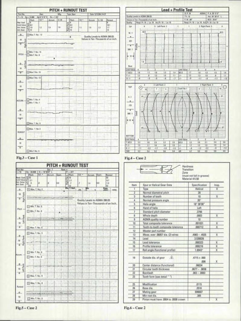
PITCH + IRUNOUT TESTPilI1ND. Din M! TVl3t Sp~r 0111'12112194/1<.21T= '4 O'.12JOl H~~O'O'R Rc_l1
Pnch TIP ~~UI1i 5.1/8 P.,h T T' Accul1'l S 1)\ fI,u"'DiII'Flqd.a..I .l1li • 1! B Bu..tV_ ell d! 6J 'IllAct V ..... ~ UI 12 U IS lin II I' U 1.1Arto..l ~ 13 ii: 13 I.
~ GMuT~ 12Duality Levels [0 AGMA 3111:03,•
fO ~ VlluBS In TBIl-'Thouunds of an inch."'''If"""i! -~- ~~..
GM,n.'1 N".I~PITCH - 'G--'n.T.~,. -- -- -- - ~•
l' , ,~.~
~~ ~ I I'10
I __ I
<r GMu.T.No. '10 ~ - -- -- --~--,
.°'·'''1 , ! ,
I~ ct,,
I
I.
~1"'9"" I -----r' • I
, ,~
t ;, ,I
8Mo1.T.N<>;I
~
i ~i.' IACClU- 810,1... T 1'10"1 ,,7, I
I,
I' i_I iT~ 1~ I - " 1 !ID i I I
-V- -- , -T =r ~~ I !: ~IG]UIIi(. T NG. I
IGULI< T 1'10 3
j -t I , ,I
RUNDUT 1 I I I 1, I I I i I....!I.... CU uu i I ,
10 I jI I"Q - ! . I
GM,nTNo"I !
Fig,.3- Case 1
PITCH + RUNOUTTESTPartN.: s.r. Rem ..
= I,m!.I
[.10 D~'2BDDD H _IB 30'0' LPrteh TtT • A-m
00
~ Pne ~ T T • Accum sp.n, \moulon.
DO
Ilu.lity Ltv.ls to AGMA 3!IO-.03-::-;-;;-:--:-;---:--t----i--,- V.lues in Ten-Thousands 01 an Inch..
El M,.. T. No" 6
I
--'---__;:-- i ' 'j- -=1 .:- - -t- ~ +!
m Max.T, NDC5.J .- .' - .:t' - 1--- '.J
RunolJ1
.JL
10
()
,El fIIlln. T. 'No,; l
. -,-,......., ,-'t -:- '--I - ... ;I-_. - - ,t· '"
Fig.5 - Case 2
!lead + Profile TestD P 28 AGMA P A. 20"0'0"
Iluillty Lallol, to AGMA m.o:t n.lo H.llJ'3Ir0" LValues ~nTilin-Thous.l!lndl or ,nlnc:tI F.W..Y' BCll. .ilSlf'Quality A.qd. Pr 10 I Le 10 A«Pr 10 I Le: 10 nlq<\. Pc 10 I lI: 10 Ac- Pe 10 /lI.l0
TIP 4 3 LtttRlnk 2 I 1 !R"ht FIonk J !
I
I . IW ~ -- : I w I
16 1" -- - v , I ,
--'-- 1,
~:.il~ -I_:.il .1.1131 - 1-'·; -
--I - - -I-:r- ~+ , =-- - l-I- 1::1-·... -'.I L ,-
~:I e 1 _-I - -=-~--::--- , - - ,- --. , -,"r 10 ~
_. J -- ---'- =\1---- -- - ,-1-=1¥ H-:~
~:. --r- t= - ----.- ,
1,9 .------' =± I- -I -j--t. t:::::::::0 l.r1
ROOt I--
l'lIm.vliiii • -' Unoi VII .. 1-'--
3 2 1 ,rWH I B 11 U U u b'U 17 IA_ 1.3 i s UiF+ U J 1J 1.0 I u 1+-_ . .l. 12 lJ 1a J 11A+ -J -5 -9 -s -1 !+ ~, -I I -I -11 -10
!
4 J LoItR.nI; ,1 I 1 211oJ1h1_J 4 -TOP
G~ • =f=:" L ==fta:...GI --'--- 4 ..!.T_NoI-4- __+-- -",,-,-j--
J11 - -1 : r--- t-.I1 ',~:I
:{ ~ ---+-, - ~'. ~r 1=lt .-I :F-r- I::'~.125 - 1- li==
-r- .,-1'-i -.' -11 • ~~:1"
~::-'!l - ,... - - r-
rIO 1 -, - :::::j -:: - f--, - - t-.- , --\' - 1-1- '.-- -~r----= t:\ ---+-. _'f-:: ;-= I=~ -- '----In--; <r-r- , oi, .-r-, -+---- 1- I-AIr---'-
1--1:::-:-1-' I~80l1Olol 1---1 1-- .-"-",.V.lul 4 J 1 1 lmlllV.lul I 2 3 4T CI':L3 1lI l.i 1.9 12 1 2.S ~. 2.2 U 3.1 U J UF+ 1.5 1.1 1.& 111 IS !+ 11 1.2 1.lI 15 UA+ -1 I -2.2 -11 -10 1 -15 H:- -.1 -12 -u -.8 I -U1C"III Ii3 M '5l 5.6 5_ W 41 50 49 SOO •. 9
Fig.4 - Case 2
HardnessTransitionZone{must not fall in groove]Material 41l50
Item Spur or Helical Gear :Data SpecifiC8tion Insp.1 TYlle Hehcal X2 Normaldja metra I pitch 283 Number of teeth 10 X4 Normal, pressure ,angll! 2D~ !
5 H'elj~angle 1'8'30'00·6 Hand 0' helix Left7 Standard pitch diameter ,3766,8 Wholedeptlt .0803 X9 AGMA,quality number 10
10 Total composite tolerance .001031 X11 Tooth'lo-moth composite tolerance .000712. X12 l Mastel part number13
,Meas, over .06857 dis. [21wires .4965- .4935 X
14 Lead 3.53602615 Lead toleranc II I .000323 X16 Profile tolerance .000216 X17 !Rollangle {functional profilel 1.1I94JO X
19 OutSide dia. of gear .s. .A715 ±.oooI.006 X
20 Center dlstancatfunctlonall .960J421 Circular tooihtfi ie kness .0677 - .065822 Backlash .003 - .000323 Tooth form (see detail " ")
25 Modilication .011526 Base dis. .3516 I
27 Mating gear 699607 'I28, Min root dis, .30529' Pinion must have .000410 .0008 crown I X
Fig.6 - Case 2

work piece stored from a setup part. Hob shiftlimits areestablished over a circular pitchrange, shifting the hob in and out to realignfrom the timed position established by theproximity device located over the top of theworkpiece. When the hob is thoroughly wornin a given area, the hob is shifted a full circularpitch ami continues across the hob face. Caremust be taken to cut reasonably good parts inroughing and to insure that no severe damageoccurs in heat treat. If a CNC hobber can beused, better profile results are possible becausethe workpiece is rotated rather than shifting thehob, which may degrade the profile.
Following are some histories which shouldmake a strong case for the cost-effectiveness ofcarbide rehobbing as a substitute for geargrinding. In fact, many applications would beimpractical to grind because of wheel diameterand cost. Keep in mind this hobbing was doneon non-CNe, mechanical hobbers, costing$250,000 - $350,000, versus gear grinders,which usually cost $1,000,000.
Case History .1. Aerospace high pressurepump gear (Figs. 1-3). Fourteen teeth, 12 DP,28° PA, .765" face width, spur, hardened to55 - 60 Rc,
A. Rough cut-double cut, .0501..030" (1.27 -.76 mm.) feed at 350 rpm with a 2" (50 mm.)diameter hob-331m. Normal tooth thickness,.1301.132 (3.3 mm.).
B. Finish-cut 400 rpm, feed .015" (.38mm.), 2" (50 mm.) diameter cutter, TiCn coat-ed, production 141hr. auto-loading.
Case History 2. Power tool application(Figs 4-6). Ten teeth, 28 DP, 200 PA, 18.58°,.68" (17.3 mm.) helical face width, hardened to48 - 53 Rc, material41L50.
A. Rough hob bed 800 rpm, .045" (1.14mm.) feed, .0701.072" (1.6 mrn.) Normal tooththickness, 1OO{hr.
B ..Finish crown bobbed 500 rpm, .025" (.63mm.) feed, ..0642/.0625" (1 .6mm.) normaltooth thickness, 601hr.
Case History 3. Aerospace application(Figs. 7-9). Forty teeth, 32 DP, 20,0 PA, .325"face spur material 431 cres, heat treat210/245,000 PSI, AGMA io.
A. Rough hob 900 rpmf.050 (1.27 mm ..)feed, 1 7/8 diameter M42 bob TiN, production1OOlhour.
B. Finish carbide TiCll, 530 RPM, .025"
LEAD ... PROFILE TESTQUIlIft) Levii'll! to AGMA 390.~3,Valu.aii: in Ten-Thousands: of-lIrflnc~-.
f'UO ".1" ,','rlual Roll [I, Pr; 10 Le: 10 Act p~:ID j La: II Re ~,Pr; 1C le: HI A~I Pr: 12 le. II
TIP -----.,-4~ _ ~e~~ _ 2 ' J~ I 2 RllJhlR.nk 3
a·, 11r: -r -r---r- --~
II
--. -
~+,
--'
l.JmitValu~ 1orf5 1.3
Z2.0
21.3
31.2
41,3 13
F-I-A-I
.9-.3
1.0.4
'1.0-1.l
,9.9
-I- 1.l-I- -,6
1.0-,8
1.0-,5
1.3-1
1,1-.S
3 Luftfla-nk 2. 21 11
.. I-..., - -
1 P.lghtFlal"lk J11 _ ,_ 21, -, .1--"~ '---1
: .'. -, ..• -t-_ -
I
,!l_TQ~th Nr 1 1~ ,.---1-,}:_" -, -I .:
'031Tap
• I
1·'1
:~ j: r'
"
, r :'~_'_ "I: r-,
" !.:" ,1-----=-,
lJmitVlJlue l 2 3 4Of,!.2 ,,' .1 is ilia" 2,1 2,1 1.2 ,9 1:1
F-/A
" ,1 ,. 1.1 ,9 -I- J ,9 .9 s .8
Fig.7 - Case 3
PITCH + IRUNOUT TESTPart No. DEln: Type: SpurT-4O 0 =3.1 HIlIO"~'U~ R 8e:;; 1150
T1P' ACl:um S.ll8Pitch Pitch TtT'" Accum S l/a PiUr1CHII~ 10 10<.£ 2.5 5,6
" 1.0 11 3,9 '.9 2.6E 12 12
R~d_ QUJ;!I ....: 10LJmltVa~ue ii '2.5ActValue ~ 1.2Art (lliaL !; 12
1.9 3,9
-lL GM,L..!N.c' 33 ~*~_~_-' ~_10 ~~{tj ~~~~=:;:~~~~=_Quality Levels 10 AGMA 390,03,= ~Values in Ten-Thousands of an tnch,
gMiii, T. No" 15P1TC~ G Min,T,: No" 21 '
-I I .-- I ~.-'--+i---f-----t.l- f----t----
c 1 'I " il-lL~~~~~~~~~, ., =-= .! ..
10 3 .: i ,. ililM ax. T.No,3lJ I
[!]Max.T.No.:l0 - ·11
!
. 'I . ,1-..:... 1 _. - - -. .':'I~I",',"
I.i': I _
I' - .! - -I ' -.I "-:.J -::::. - ,:. ',' .
A.CUM. GMlo,T. No,c29ElM,n. T. No" 11 I.
,II-I .
RUNCUT lilM",Y:,NO:1S: - !'" -. I' -:C'3'~ :,.'r. -, ::-=2'.::--:- =~~-',......,-...,.......I·-"-· '"7'--+--:-:1.~-.· ~::-::'::±-::-:::-- t-:-.:-.-:-:-: : -. "":-F- :~~
IQ
Fig.8 - Case 3
MAY/JUNE 1994 1'9

AGMAW32 DP 20"40 Teeth
.1101rCE .0005 nCE32 Micra
.001 A mlxorCham4 Pl
.005 R Max4PL
.779 ± .002 Oia
Hcne if necessary
-L A 8 .0015 I
Option I Blink per p,m!
Option 2 Op1ional ,processing. Screw machine blank, double disc grind. Bore10.L hone to final sIn.
T. 'Heartrelt rAW MIl-H·6874 WIth rhe exc.poon rhat til, range shall be210,000 ID 245,000 psi and the impact valua shall be 18 ftIlllilmin.
Fig.9 - Case 3
PITCH + IRUN'OUT TESTP r R m ~• II 0 IUIJO H. IS '0'0' R
PJtcfL Tt c urn _SDi!ln ...., PRe"" ., Accum SpIn unout
p' • .9:82
-L. 8MIlI.T.No:I __ ...J',--;o.,.J:I...-_-I-,_f"_-·_I.- "j' .. ~.,.,101 _- --L._+._+I_·, t- 1 '
-oi. _-~---~~~ __ -_l'""-__ , Qual!\, LavelSlo AGMA 390.00.ii. 1 Values in Ten-Thousands of an inch.
8 Min. T. Nil.: 10 __ +-_-1-e_I---t-_-I--_:"", -+---;,--+--P'tch - 8 M". 'r.~.:3 __ +-----:" ~r_+-_r'[-.;.:•._=+---=-::~ 11''::'-''':--+'.:....~•• I!--.:..I--:.:-:....
-~-+_,,---!-:.... ..+-I-I---I.-- ~1 .,.1 ~l 1 • 1· . r:.: i ., - -
10 .jj I =-l .. L t,·. -"t' 1.1 - ...= 1 '~.,. ,,-~; - -.j
0- ElMoLT.'! •. t I l' L. -1-- ,-- .1 -
t I - -. --.: ,,'=... '.- ----.::==-...--.A-10 I . ~ ,- .-:-:.:- ~ -_ • - -- -_. - - .' . --
t +- 1-- 1--- '1--- - 1-- 1----, _. -.8Min.T No.:) T -'.::- -- - .._.!"1-0
Fig.n-eo~4
Lead + Profile TestQ"t'" ~tIt '" AfiMII :I!iD.b3 D P ,4 AGMA jp II.lII"O'O"Vlklu.' __~Df.~ I~Pi Th ,3 Hot ,goa II" It
FW" SCO .'el'Iluthl¥ IItqd.Pr.-llt.1 AclPr- /lr, 10 Roqd.I'I:- Ilt:. A<lPr-Ilr,'O
np • 3 ltItFlonl<2 , , 2 RiO"' RonI< 3 •, ,'!.1
I -,-J 1i t -~ n - -" 4J,lI70 IV 1 :1 ~.~ "'0 , I
~+I t ,-.-
I j , . - . t~- - •!OIl' 11', : - - - -- ,I)~I,
~ '0 ~
f--, -I-~
1: . illi - - . : ,A11.! 4 11 ;' ,,n- -r= -:~- ...:l- • t -:.. >--. i --
I~Vt" • 3 'i I ,,,-~Voluo ,'-'7 '<3 •T+ u II ~O .. <l + 5.1 1.1 SoD 1.2 53f+ ·~ ,~ 51 5., U + U U ~O ~O SO11+ • -, .s 1 .z -/- ,~ -1.8 -Z5 -1.0 -llK-d\," ..I. +1+ ++ +1+ +1+ ++ +1+ ++ -
010 • 3 ltltA .... 2 1 1 2ItovlnA''Il.30TOP r=:'-'- !--------1 . ., 'J_Nol , -t--T _'0
. - t- - - t---
2:1_. - L_~'" r--::::: 1--
~ cr --=-;- ......L-
88 ~, -1'\1 IfiI
.I ,--- - .. j=-1 I- '. [IS' -1- -_..25 - I.":::.-; - - c--.- ,,1 >~ >'1 . :-= ;R..,
.~ !-t..: --=tt f-=r I-- '::trill· 'I ..' F3 I
~ 10 1 .\ i- i- .-<1\ ~.2\.. f-=::l+L ~-i) .- '7'-
.1 r\ ,- r-l=- r\... "r - !-- .~ -=~..:: I~-- ==/=-.:..;:::: f~- -t I:""':::;: -- . I:=:::BOnDM ,,, :-- - - l--. --I--- - - 1-
GM'V.,.. • J 1 1 lIn1.V.lue I 2 3 •T W<lS U 30 U 2.! II bu 11 zs z.r ,U 2.5 ,
F+ 11 IT 13 11 ,1 1+ 'S 2.0 U ,IJI I
II-/- 11 IJ I ~ , 1.3 I-/- I -u 1~ -.' .JI ,UII[:118 l' l~ It II U JIll 1.l U n 1.5 61
Fig.W - Case 4
PIT'CH t RUNOUT TES,TPAnNn: .,.13 D .'1.000 ,'S-0'0 R = !182
Prtch T' Accum ISi'iM .M Phch TIT' c m span ul'1'oult-qd QiJl ,"!~ ~ 8
L.JmftVllul .l! 5!I~
5.8 IS.O~~!!h!. ~ 8 ] U 1.J .1 .1.3 2.B 1.3 .0
IDulL 13 I"" 11 I~
-L. [!]M .. TNo,. I
:Ilol '.I0Il:
1!M1 -:1 !L_ a ~:;'naI
• J10 'I --'- J j I- 1 ,I,-~ -- ... GuslIly !levels to AGMA 390.00.
I oi , Values in Ten- Thousands of 10 inch. I,I- -r - - "
6MIO.1 N.:la
1 .-'Pl!<:h - I --
I8 M,n.T.~ •. 3 1 I; ~. I, .' j -:.= --F'-I- I- I-Ll 1 - I-, . 1 -
I10 ! ~ 1 L_ --'f-- . T - rm M.~ TN e.
t"I0- .- ! ..1 1 _I • -
13M .. T N.'9 I -- r~ . ] .. 1- 1:-: - .:-->
ID J , - y*-~ :.::: ,~- 1- _ •
1 - --- ~ .:::f~l==': h I-=--J , c __.r: :I-~- ~==~-=r~ .- -
t I I --~ ,. .=EM.. ~~2' --;-:- --=-= r= - ,-..:-~ .--= !. .-~ I':;~F- ~-lAc,,,,,, "l ~ J e-= ~ t 1-8"'" T !io.:'11 .~
, I 1. . i ,.1=
..:lL - ---=- t10 J .....,..I~ -
-' ~'1 I -
I I I 1- - .,-~I -,- -i--I-S-Lr=r.:: _ .:t- =. -:"1 -1-:[!lMtLTNo.:' I _ - ~-=: 'J _ _. -:
[!l Mox.T.No·' -=: !:~;:~~r.:::::r..=:"= ..::"E::I;:"'"~' -RunQilt :;:;1:'-:;t..:- •. - _. • - I: .' 1.--
·1 1 - .. ;::.. - .-=:- --- I- I~-::;- rr 1--::1 - - -:- .~ 7.:.: - .L-" 1::-...L.
10 'j i- ~.==::- 1-' ..-- - -:.... j..::.....:...: '1"- ' .-I-- .t-=- ~ 1=-'
El Min. T loIo.:T t ,.:;'::I'=-_. ..
Fig.12- Case 5

(..64 mm.) feed, 1 7/8 hob diameter, 281hr.Case History 4. Lift truck motor armature
(Figs. 10-1 I). Thirteen teeth, 14 DP, 20°PA, 18.83° helical, .97 (24.6 mm.) facewidth, 86L20 material, induction hardenedgear 58 - 63 Re.
A. Rough hob 1" diameter hob, 800 rpm,.040 feed, 6711u. Normal tooth thickness,.1406/.1387.
B.. Finish hob 350 rpm, .025 (.64 mm.) feed,crowned, .0002/.001" (.005 - .025 mm.) 24/hr.
Case History 5. Lift truck armature shaft(Figs. 12-13). Thirteen teeth, 14 DP, 20oPA,14.7SoheIi.x. face 1.3" (33 mm.), crown-bobbed to AOMA 8..
A. Rough hob 600 rpm .. OS5" (1.4 mm.)feed, ]-7/8" (47.6 mm.) diameter hob TiCn,45/hr.
B. Finish hob 325 rpm,.025" (.64 mm.)feed, I-7/8" (47.6 mm.) diameter cutter TiellI7/23/64. Normal tooth thickness •. [233/.1208(3.Imm.).
C. 14T, 16/32DP, 300PA spline, 2.12" (53.8mm.) face-finish splined, 22/48 Rc core hard-ness with carbide TiCN 1-7/8" (47.6 mm.)diameter hob. 341hr.
For variation. Fig. 14 depicts a cast toothform pump gear re-hobbed in alloy C
+;000-;001
Involute FormNumber QfTeeth 11Pite h Oiarneter 1.375Pressure Angle 28"Circular Tooth Thickness .2104Root Diameter 1.Z3ll ApprOM.Center Distance With Similar Mate 1.5008 acklash Per Pair .003Dimensions Over Two .375 Oia. P.ins2.153
Fig.l4
PITCH ... IRUNOUT TESTPori No: S.,· B Rem.:!
>15
!~13 Dp= 14.000 H. = 15"0'0' RPitch TH. • 'Accum.. Span. ~ Pilch TH, • Ace""', Span, Runou!
~eqd.au.al ~ 8 I ~ 8I ,m~V.I", I.: 5,8 I 10 5.8!"OLV.I." 'ii 6 ,7 1,6 .5 I~ 4~.L!lu.!' ~'14 115
lS.0.7.1 .7
U~.
~ccum. '-,
~I10 't
~--u:;~_ __:1::: -
--r--- ... +- ..4- -
I!I Max. T. No.: 1 _=t==-- f-.
Runoul
Fig. 13 - Case 5
TabID I
Rockwell DeflectionISO Hardness Resistence W Co Ti fa C
I
I 60 5 5 0 '6P20 901 90 83 10 15 15 9
I
70 4I
3 0 6M10 91.5 100 86 9 11 11 8
89.5 120 75 '5 0 0 5M15 I 93 220
I95
I 9 10 12 7 I
89 150 85 3I
a a :5K05 93 230 9'7 8 3 7 7
, SA 4
I
0 0 , :5KmI
90.5, 120 90 7 1 2 I 6
Table ill
Feed Module IOPt Flaugh mm (in) Finish mm (in)
! III II
>12 3-4mm/rev 2-3mm/rev(<2J II 1.120- .160"/rev) [.080 - .120"/rev)
> 12 I 2.- 3.5mm/rev 11.5- 2.5mm/rev[<2J i (.008 - .140"/rev) (.060 - .1OO"rev}
!
'MAY/JUNE, 1994 :2,1

ADVERTISERS INDEXI
Reader Service No. Page No.
I AfW SystemsI
7 23I
ASM International 37 47
American Pfauter, L.P. 1 !FC
I American Metal Treating Co. 34 48I,I
I Bourn & Koch Machine Tool Co. 10 11I
I
Contour Hardening 16 47
I Detroit Broach Co. 17 47I
I
Diagrind Inc. 8 39
Diamond Black Technologies, Inc. 26 46
Eltech, Inc. 32 48
Fair/ane Gear, Inc. 11 12I
Forest City Gear 18 6
GM1-FHUSA 36 5
I High Noon 4 4
INfEX Information Export 8
I M & M Precision Systems 3 2I
I Mstrscope Corp. 14 47I
I
National Broach & Machine Co. 30 BC
! Normae, Inc. 12 42!
Parker Industries 9 II
Pfauter-Maag Cutting Tools L.P. 2 I
Prentice-Hal!
I
47I
IProfile Engineering, inc. 33 48
I Pro-Gear Co., Inc. 31 48I
I Starcut Sales, inc.I 5 4
Sunnen Products Co. 19 47
United Tool Supply 35 42
Winter & Son, Ine., Ernst 13 47
22 GEAR TECHNOLOGY
Table IIII
Hardness HeRI
Speed mm/min (in/min)
50-55 70+90(220-2901
'55-60 160 + 70! (190- 220) I
I60-65 50 + 60
I(160-190)I
Table IVSpeed' mm/min (in/min)
I
Module DP
1 +5 60 + 90(5-25) (190 - 290)
6+ 12 50 + 70(2-4) (160 - 220)
I
> 12 30 + 50«2) 96 -160)
Hastalloy. This presented a problem for theelectromagnetic sensor, since this material isnon-magnetic.
Tables I-IV (Ref. 2) define typical carbidegrades, liberal feed rates for roughing and fin-ishing and suggested speeds versus hardnessand speed versus module. We tend to be moreconservative with our speed and feeds to savehob wear and improve quality ..
In conclusion, carbide rehobbing is anextremely economical approach to removingdistortion caused by heat treatment. Besidesapproaching gear ground quality levels and fin-ishes, carbide rehobbing can be used withsmall hobs capable of approaching blend-cutshoulders, which larger grinding wheels,including double belicals, cannot reach.Hardware cost is fractional, since the samemachine can be used for roughing and finish-ing and mass production is readily obtainablewith automatic loading. This process isaviable alternative to gear grinding. I.References:1. Glatzeder, Hans. "Skive Hobbing HardenedGears," Liebherr Versahntechnik ,GMBH.2. McElroy, William E. "Using Hobs forSkiving: A Pre-Finish and Finishing Solution."Gear Technology, May/June, 1993.
Acknowledgement: This article was first pre-sented at the AGMA Gear ManufacturingSymposium in Detroit, MI, Oct. 10-15,1993.
"YOURFREECATAILO'GKNO'CKE,DMYS'OCK·S,'OF'IF"We get that art of comment all thetime. People are impre sed that ourfree Con uruer Information Cata-log lists so many free and low-costgovernment booklets. There aremare than 100 in all, containing. II
wealth of valuable information.
They tell you how to make money,how to save money and how toinvest it wisely. They tell youabout federal benefits, hou ing andeducation your children. They fillyou in on nutrition, jobs, health,cars, travel and much more.
Our free Catalog will very lik,elyimpress you too. But first you haveto get it. Ju t end your name andaddress to:
Consumer Wormation CenterD partm.ent KOPueblo, Color.ado8HHl9'
A publJ<: serviee of .h ts I"'bhcarioo and the Ccmurner Inf",·mauen C.c'lIItr af lfito U. S. GeTitt"aI Sct'\'iCC!i, A(llmrd~lfinioo.
ANJ Sys1ems Co. announces that itIS now a manu1ac1unng source of spiralgear roughing and finishIng cutters and bodes,
We also can rernanufaclure most spiral cuI1er bodesand can manufacture new spiral bodes 111 diameters01 5" through ·9" at presentAm can also supply roughIng and finishing cutters,hardware and replacement parts for most 5"- 9"damelel" boees,
, Whe!her rt'S manufadunng or remanuladunng,consider us as an allernall\1e source lor replacementparts and hardware as v.ell as bodes and cutters. 612 Hamson • IRoyal Oak, Michigan 48067'Ibu'~be In f(){ a pieasan! surprISe Telephone (810)544-3852 •. FAX (8l0) 544-3922
CIIRCL'E A-7 on READER REPLY CARD
MAY/JUNE 1884 23

Minimizing Backlashin Spur Gears
Richard L. ThcenConsultant,
IMinneapo,lis. MN
NomenclatureB - Arc on both reference circles that corresponds to Bb 011
both base circles
Bb - Backlash on line of action
C - Distance between centers of reference circles
Cb - Ba ie center distance, {N + 1I)/2P or m(N + n)12
m -Module
N - umber of teeth on gear
n - Number of teeth on pinion
P - Diametral Pilch
p - Circular pitch on both reference circles, rrJP or 1m1
p12 - basic tooth thickness
R - Radin of gear reference circle, NI2P or mNI2
r - Radius of pinion reference circle, nl2P or mn12
Rb - Radius of gear base circle
rb - Radius of pinion base circle
S - Arc on both referenc circles that corresponds to Sb 011both base circles
Sb - Space online of action due to an increase in center distance
llT - Deviation From p/2 on gear reference circle
ill - Deviation from pl2 on pinion reference circle
IITb - Change in tooth thickness on gear base circle
tlrb - Change in tooth thickness on pinion base circle
~ Profile angle of generating rack
1/1, - Pressure angle
24, GEAR TECHNOLOGY
AbstractSimplified equations for backlash and roll
test center distance are derived, Unknownerrors in mea ured tooth, thickness are investi-gated, Ma tel: gear design is outlined, and analternative to the master gear method isde cribed, Defect in the test radius methodare enumerated. Procedures for calculatingbacklash and for preventing significant errorsin measurement are presented.
Introd uettonAn important part of designing for mini-
mum backlash is the prevention of significanterrors in measurement Circular tooth thick-ne s, for instance, . is not measured directly,but. is calculated from an equation that pre-sumes perfectteeth. A a result, a master gear- even if perfect - may not indicate thecenter di tance at which imperfect gear will.mesh tightly with each other. Moreover, themagnitude of the error in measured tooththickness varies with the number of teeth onthe master gear.
Mea ured tooth thickness also varies withdepth of contact and active face width, so therna ter gear should be representatlve of thegear that males with the wcrkgear, But mostmeasurements are made with general purpose,off-the- helf master gears.
Significant errors exit in many. if notmo t. roll test. measurements. Evidence forthl i the discrepancie in measurement thatarise when the arne gear is inspected by dif-ferent people (buyer and seller, inspection
andproductioll departments, differentinspectors using tile same te t equipment,etc ..). The typical respon e lias been to stan-dardize tile test equipment and in pectionprocedure - a maneuver which can reducethe discrepaneies In measurement, but notnecessarily the errors in measurement. Thepurpose of this article is to show how to' dealwith errors in measurement when de ignlngfor minimum backlash.
Basic 'GeometryA very simple way of treating backlash is
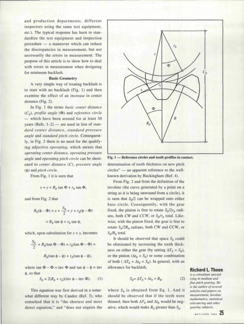
to start with no backlash (Fig. I) and thenexamine the effect of an inc rea e in centerdistance (Fig. 2),
In Fig. I the terms basic center di lance(Cb), profile angte (cI» and reference circle- which have been around for at lea t 30year (Refs. l-2) - are II ed in lieu of stan-dard center distance, tandard pressureangle and standard pitch circle. Consequent-ly, in Fig, 2 there is 110' need for the qualify.img adjective operating, which means thatoperating center distance, operating pressureangle and operating pitch circle can be short-ened to center distance (C), pressure angle(¢l) and pitch circle.
From Fig. 1 it is seen that
x + y = Rb tan cI>' + rb tan cI>',
and from Fig. 2 that
which. upon SUbstitution for x + y..becomes
where tan (})- ¢I' = inv ¢I and tan <p - III = inv,~, 0 that
Sb ""2(Rb + rb)(inv <p - inv 'cI»,. (])
Tills equation was first. derived in a some-what different way by Candee (Ref. 3), whoremarked that it is "the shortest and mostdirecteqaation," and "does 110\ require the
Fig. 1 - Reference circles and looth profiles in contact,
determination of tooth thickness on new pitchcircles" - an apparent reference to tne well-known derivation by Buckingham (Ref. 4).
From Fig. 2 and from the defininon of theinvolute (the curvegenerated by a point on astringes it is being unwound from a circle), itis seem that SII2 can be wrapped onto eitherbase circle. Con equently, with the gearfixed, tile pinion i free to rotate SII2rb radi-ans. both CW and CCW, or S,jrb total. Like-wise. with the pillion fixed, the gear is free torotate SII2Rb radians, both CW and CCW, orStlRb total.
It should be observed that space Sb couldbe eliminated by increasing the tooth thick-ness on either the gear (by setting IlTb :::::Sb)'ortbepinion (rub = Sb) or some combinationof both ( ATb + Atb"" Sb}. In general. with anallowance for backlash,
(2)
Ri:chalrd L Thoenis a consultant special-i~ingill medium GIld
fine.pitch gearing. He:is the author of severalarticles (lmi papers nil
measurement. invotm«mathematics. statisticalto/er(lI!cing and othergearing subjects,
MAY/JUNE 1994 25
where Sb is obtained from Eq. 1. And ithould be observed that if the teeth were
thinned, then both ATb and Atb would be neg-ative, which would make Bb greater than Sb'
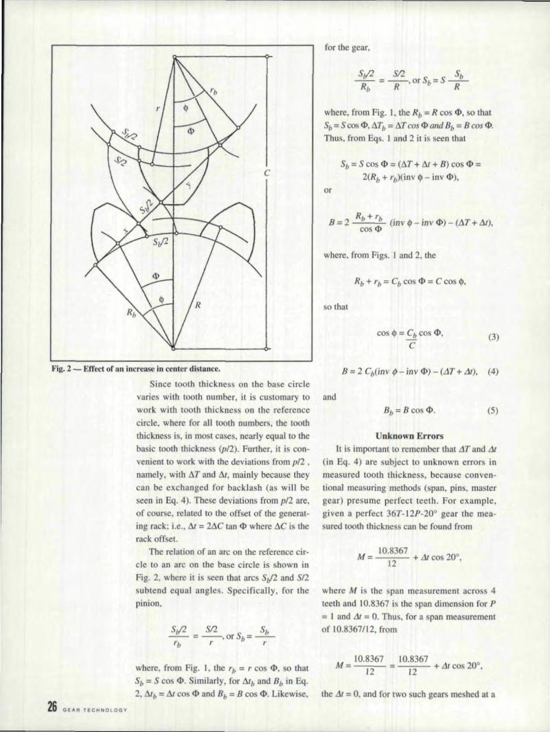
Fig..2 ~ Effect of an increase in center distance.
Since tooth thickness on the base circlevaries with tooth number, it is customary wandwork with tooth thickness on the referencecircle. where for all tooth numbers, the tooththickness is, in most ca es, nearly equal. to thebasic tooth thickness (pI2). Further, it is con-venient to work with the deviations from p/2 •
namely. with AT and At •.mainly because theycan be exchanged for backlash (as will beseen III Eq. 4). These deviations from p/2 are,of course. related to the off et of the generat-ing rack; i.e .• At = 2AC tan ¢l where Ae is therack offset.
The relation of an are on the reference cir-cle to an arc on the ba~e circle is shown inFig. 2, where it is seen that arc S,)2 and 512subtend equal angle . Specifically, for thepinion,
Si/2 SI2. ... Sb-- =--.orSb=--·-rb r r
for the gear,
Sv'2 SI2 Sb-=-orSb=S·--
Rb R' R
where, from Fig. I, the Rb =R cos <1>, . 0 that
Sh ""S 'cos <P. ATb = tli cos <I> and Bb = B cos <1>.Thus. from Eqs .. I and 2 it is seen that
Sb = S cos <I> = (AT +- At ... B) cos <I> =2(Rb + 'b)(inv 4> - inv (I),),
or
Rb + rbB = 2 (mvl/> - il1vcJ» - ( T ...Ilt),cos ,q,
where. fromFigs. I.and2, the
so that
co 4> = Cb co 41"C
(3)
B = 2 ebOnv ¢I- inv (I) - (AT + At), (4)
(5)
Unknown Errors.It is important to remember that .1T and At
(in Eq, 4) are ubject to unknown errors inmeasured tooth thickness. becau e conven-tioaal measuring methods (span, pins, rna tergear) presume perfect teeth. For example,given a perfect 36T-12P-20° gear the mea-sured tooth thickne s can be found from
M = 10.8367 + Lltco 200,]2
where M i the pan measurement aero 4teeth and .10.8367 is the pan dimension for P
;;;;;I. and At = O. Thus. for a span measurementof 10.8367112, from
M = 1.0.8367 10.8367 -- 200--=-1-="2- = 12 + At cos - ,where, from Fig. 1,. the 'b = reos I), so that
Sb = S cos 4>. Similarly, for Alb and Bb in Eq.2, Alb = At co I) and Bb:= B cos <1>. Likewise, the At = O. andfor two uch gears me hed at a
26, GEAR TECHNOLOGY

center distance of C "" Cb"" (36 + 36)/(2 x12)= 3 inches, the backlash dong the line ofaction is zero; i.e, from Eqs. 3, 4, and 5, theB'b "" O. However. for the same span measure-ment on a gear that has been photographicallyreduced to P "" 12,05, from
10.8367 10.8367M ""---:-:-- - --:-:c-:-- + L1t cos 200
,
12 12.05
the Llt "" 0,00399, Cb"" 36H2,OS, and at C = 3,the Bb "" 0.0012, not Bb = 0 as for P "" 12.Similarly, for a gear that has been photo-graphically enlarged to P = 11.95, the L1t =- 0.00402, Cb = 36/11 ..95, and at C"" 3 the Bb=- 0.0009 (and interference).
For the aforesaid 36T-12P-20° gear, thedimension over 1.92 pins is 39.0886 for P "" Iand .L1I = O. Thus, for a pin measurement of39.0886/[2 on a P = 12.05 gear, the L1t =0.00502 (obtained by solving the pinequa-tions for L1t), and for two suchgears meshedat C "" 3, the Bb "" - 0.0008 (an interference,versus a backlash of 0.0012 for span). Simi-larly. for the same pin measurement on a P =11.95 gear, the L1t = - 0.00494 and Bb ""0.0008 (versus an interference of 0.0009 forspan) ..In short, for both P = 12.05 and 11.95.the backlash for pins was opposite in sign tothe backlash for span.
It is of interest to note that the error inbase pitch, relative to P "" 12, was 0.0010inches for both P = n.os and 11.95,. and thatan error of this magnitude is not uncommonin formed gearing (molded plastic, die cast,powder meta], stamped, cold-drawn). Further.when the combination of tolerances (for out-side radius, tip round. bearing clearance, cen-ter distance) is large relative to whole depth,as in the case of fine-pitch formed gearing, itusually is necessary to design for minimumbacklash. 0 as to avoid a contact ratio of lessthan unity (Ref. 5).
And it should be noted that no generaliza-tion can be drawn from these idealized exam-ples, since the error :in measured tooth thick-ness varies with the number of teeth spanned,the pin diameter and the tooth number.
When the two-flank roll test is not practi-cal, the .L1T and L1t (in Eq. 4) should beadjusted to account. fOT the allowable devia-
Fig..3 - A mesh in whlch some 'teeth fail to make contact.
tions in runout, tooth alignment, profile andspacing. An approximate adjustment can bededuced from similar designs, namely, fromthe discrepancy between calculated backlashand measured backlash - which alsoincludes the aforementioned unknown errorin measured tooth thickness. But if similardesigns are not available, then it is necessaryto estimate the individual adjustments (Ref.6). and to assume a value for the unknownerror in measured tooth thickness.
Characteristics of Master 'GearsWhen a master gea.r is used to measure
tooth thickness, the teeth will be thinner thanthe value indicated by the master gear. notthinner or thicker as when span or pins areused. To illustrate. consider two gears -one imperfect and one perfect - in meshwith a master gear at the same center dis-tance. It is clear that the teeth on the imper-fect gear will be thinner than the teeth on theperfect gear (Ref. 7). As in all functionalgaging (gears, splines, screw threads, bores),size is sacrificed for defects in form andposition, Consequently, since the teeth arethinner than that indicated by the mastergear, the backlash win be somewhat greaterthan that indicated by Eq. 4.
Moreover, the magnitude of the error inmeasured tooth thickness will vary with thenumber of teeth on the master gear. This canbe easily confirmed by meshing gears of vari-au tooth number with a ingle gear ofslightly different pitch and measuring boththe tooth-to-tooth composite variation (alsoknown as tooth-to-tooth composite tolerance,
MAYIJUNE 1994 21

28 GEAR TECHNOLOGY
iooth-to-tooth compo he error and originallyas klckaut [Refs, 8-9]) and center distance.
For example, when L92T-127 P-20oand180T- L20P-20° master gears are rolledtogether. the kickoutis only about 0.0002inches, despite the fact that the difference inba e pitch is 0.0014 inches. But when 120P-20° relatively high-grade gears (error in basepitch ~101?l of 0.0014 inches) of variou . toothnumbers are rolled with the 192T-l27P mas-ter gear, the kickout increases as the toothnumber decreases. to about 0.0019 inche fora 12T-120P pinion. This effect, which is well-known (Ref. 10), is the result of partial toothcontact (see Fig. 3), the degree of whichvaries with contaet ratio. Converely, themagnitude of the center distance error -namely, the amount by which the maximumcenter distance exceeds the sum of the refer-ence radii - decrea es as the tooth. numberdecreases, from about 0.006 inches for the180T-120P master gear to about 0.003 inchefor a 12T-120P pinion,
A single master gear, therefore. should notbe used to check any and all tooth numbers.The master gear method. has, in Mark Twain'swords, "a certain degree of merit .. " but Likechastity - it can be carried too far!"
Master Gear DesignThe ideal master gear would have the
same tooth number, same depth of contactand same pitch circle as the gear that matewith the gear to be inspected; i.e, with thework gear. And when the face width of themating gear .is less 'Ihanthe face width of thework gear, the idea] master gear would havethe arne face width a the active face widthof the mating gear.
Becau e depth of contact. depends uponthe outside radius of the mating gear, the tiprOUI1d or chamfer 011 the mating gear, and thecenter distance between mating gear and work:gear. all three of which vary, the master gearhould be designed to match the maximum
depth of contact. Specifically, the out ideradius of the master gear should be the sameas the maximum outside form radius of themating gear (maximum outside radius less theradial effect of minimum tip round or cham-fer}. And the tooth thickness of the mastergear should be such that the maximum roll
te t center distance between rna ter gear andwork gear is the same as the minimum centerdistance between the mating gear and thework: gear.. That is, for B = 0 in Eq. 4, the
(6)
where ..1T is for the rna tell' gear, inv fJ iobtained from Eq. 3 (wherein C i the mini-mum center distance between mating gear andwork gear), and At is for maximum tooththickne s of the work gear.
The tooth thickness of most work gearswill be less than maximum, so in most rolltests the depth of contact between master gearand work gear will be slightly greater than themaximum depth of contact. between matinggear and work gear ..
In most ca es an acceptable approximationto the ideal tooth number can be obtained bysimulating the roll test on a computer. In par-ticular. the idea] rna fer gear is meshed withthe work gear, and then akickout, equal to thekickout tolerance. is induced by alteringthediametral pitch of the work gear while main-taining the center distance by reducing thetooth thickness of the work gear. Next. thetooth number is altered, but only to the pointwhere there is no significant change in kick-om or tooth thickness,
It is of interest to note that the same com-puter simulation can be u eel to establish real-istic tolerances for rna ter gear . The proce-dure is the same. except that, instead of toothnumber. the diametral pitch of the mastergearis altered. The re ultingchange in diametralpitehi then converted into a change in basepitch. which. in tum. i converted into toler-ances for circular pitch and profile ..
And it is worth noting thai the arne corn-puler simulation can be used to determine thetight-mesh center distance for a gear pair withdifferent thermal expan ion . At elevatedtemperatures, for instance. the diametral pitchofa metal gear will be different from that of amating plastic gear, which means that 'theequations for tight-mesh center distance arenot valid.
Alternative to Master GearsFrom the tandpoint of the designer. tile
master gear method leaves milch to be
desired, Aside from the meed for a variety oftooth number and face widths (usually notavailable), there i the aforementionedunknown error in measured tooth thickness,Also, there is the uncertainty in kickoutbetween mating gears - a i evident fromthe fol]owingiUustrat.ion, Consider a 20Pma ter gear, two 19.95P gears, and two20,05P gears. an perfect and with the sametooth number. The kickout between the 20Pand the 19.95P win be about the same asbetween the 20P and the 20.0SP. But therewill be no kickout between the 19.95P gears,nor between the 20.05P gear. And the kick-out between the 19.9'5P and 20.05P wd[approach the slim of their kickouts against the20P. In short. the designer has no w,ay ofknowing how the kickouts win combine.
The unknown error in measured tooththickness and the uncertainly in kickout canbe avoided when the tooth thickness of oneor both members of a gear pair i readilyadjustable. For instance, when one memberi a bobbed pinion and the other a formedgear (molded plastic, die cast, powder metal.stamped), the hobbing machine operator cansimulate the assembly process by drawingparts at random from the geaJ lot and usingthem 10 check the pinions. The pinion speci-fieacion would read: ROLL TEST CENTERmST ANCE WITH ANY MATING GEARX.XXXXIX.XXXX, and K]CKOUT WITHANY MAHNG GEAR .XXXX. Am 0,
because all teeth are omewhat un ymmetri-cal and misaligned, the pinion drawingwould identify the mating Ilank and activeface width.
RoU Test Center DistanceEquations for roll test center distance are
derived from Eqs. 3 and 4. That. is, for B = 0in Eq. 4, the
m· LlT+m,inv 1/1 = inv '*' + IlT + Llt , - ................-
2 c,and from Eq. 3,.
cos tPC=Cb---,
cos 1/1
total composite en-or, and to ales er extent asrollout) must fall withinthe limits of ron te t
center distance, and since Eqs, 7 and 8 arevalid only for perfect teeth, it follows 'that thecorresponding limit of LIT and III are thelimits of perfect teeth. In other words, therollout must fall within the size tolerance.
It is pertinent to note that. the Germanequivalents of rollout and kickout are alsosingle words. namely, Walifehler (roll en-or)and Wdlzsprung (roll jump), respectively.
From Eqs, 7 and 8 it. is eenthat inv q,.must. be converted into cos 1/1. This conversioncan be easlly carried out on programmablepocket calc 1.1letors Lhat sell for a little as ·30(Ref.Ll ), Even so, the test radius method,which was devised to bypa s Eqs, 7 and 8, isstill in wide pread use.
Test Radius MethodOriginally, test radi.i were obtained by
simply adding LlII(2 tanlP) and IlTI(2 tan IP)to the reference radii of the work gear andmaster gear, respectively. But, since (Lit + Lin!(2 tan tP) is just the first term of an infiniteseries (Ref .. J 2) that method was subject to asignificant error.
Nowadays. the test radius of the workgear is defined as the radial distance from thecenter of the work: gear to the reference circleof the master gear, as obtained by etting AT:::::0. (in Eq, 7) and subtracting the referenceradius of the master gear from the center dis-tance (Eq. 8).
It is of course necessary to . et tAT :::::0 inEq, 7. since the test radius of the rna tel' gearis silfobtained in the original way •. i.e., byadding LlTI(2 tan ,qJ) to the reference radius.Asa result, the designer is forced to specifythe master gear tooth number (or range oftooth numbers), since the test radius of thework gear varies with number of teeth on themaster gear. (The raJlge usually narrows to a
(7) ingle number for large value of Ilt.) In addi-tion, the designer is forced to specify a toler-ance on master gear tootb thickne .• ince theerror in work gear tooth thickne s varies withmaster gear tooth thickness.
For example, given an 8T-20P-20° pinionwhose tooth thickness is 0.02830 inches
(8)
Because the total composite variation greater than the basic tooth thickness ('1.0
(also known as total compo: ite tolerance, eliminate undercut), and a 40T master gear.
M"VIJUNE 1i94 29
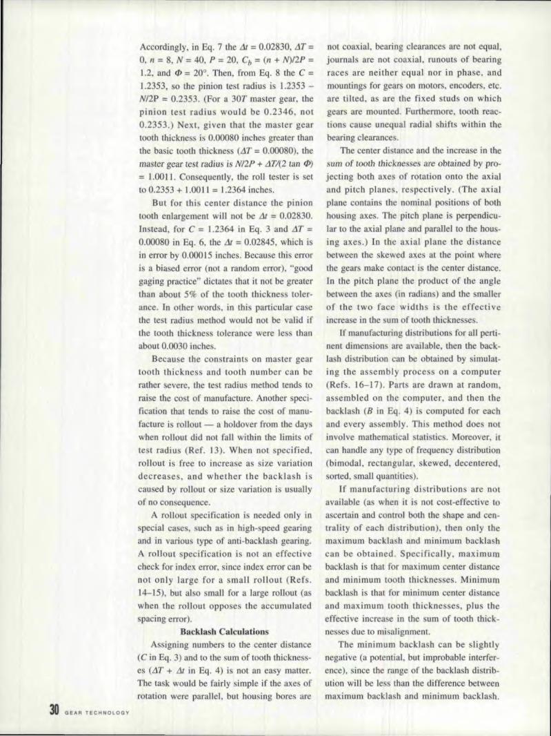
30 GEAR TECHNOLOGY
Accordingly, in Eq. 7 the .1t = 0.02830, LlT:=
0, II = 8, N = 40. P' = 20, Cb:= (n + N)/2P :=
1.2, and (JJ = 20° .. Then. 'from Sq. 8 the C =1.2353, so the pinion test radius is 1.2353 -N/2P ;;;:0.2353. (For a 30T master gear, thepinion te t radius would be 0.2346, not0.2351.) Next, given that the master gear1001.11 thickness is 0.00080 inches greater dumthe basic loath thickne (.1T = 0.00080). tilemaster gear test radius is NI2P + LlTI(2 tan f/)
= 1.00 l l , Consequently, the ron tester is setto 0.2353 + ].00 11 = 1.2364 inches.
But for thi center distance the piniontooth enlargement wiill not be .1J = 0.02830.Instead. for C = 1.2364 in Eq. 3 and LIT =0.00080 in Eq. 6, dIe & = 0.02845. which isin error by 0.000 15 inches. Because this erroris a biased error (not a random error). "goodgaging practice" dictates that it not be greaterthan about 5% of the tooth thicknes toler-ance. In other words. in this particular case'the test radius method would not be alid ifthe tooth thicknes tolerance were res thanabout 01.0030. inches.
Because the constraints 011 master geartooth thickness and tooth number can berather severe, the test radius method lends 10
raise the cost of manufacture, Another speci-fication that 'lends to raise the co t of manu-facture is rollout-e- a holdover from the dayswhen rollout did not fall within [he limit ofte t radius (Ref. 13). When 1I0t specified,rollout is free to increase as size variationdecreases, and whether the backlash iscau ed by rollout or size variation is usuallyof no con equence,
A rollout. specification is needed only inspecial case, uch a in high-speed gea.ringand in variou type of anti-backlash gearing.A rollout specification is not an effectivecheck for index error, since index error can benot only large for a small rollout (Refs.14-15), but al 0 small for a large rollout (aswhen the rollout opposes the accumulated. pacing error).
Ba.cklash CalculationsAssigning number to the center distance
(C in Eq, 3) and to the sum of tooth thickness-es (LIT + Lit im Eq. 4) is not an. easy matter.The task would be fairly simple if the axes ofrotation were parallel, but housing bores are
not coaxial, bearing clearances are not equal.journal are not coaxial, runouts of bearingraces are neither equal nor in phase. andmountings for gears on motors, encoders. etc ..are tilted. as are the fixed studs on whichgears are mounted. Furthermore, tooth reac-tions cause unequal radial shifts within thebearing clearance .
The center di lance and the increase in thesum of .tooth thi'cknesses, are obtained by pro-jecting both axes of rotation onto the axialand pitch planes, respectively. (The axialplane contains the nominal positions of bothhou ing axes .. The pitch plane Is perpendicu-lar tothe axial plane and parallel to the hou -ing axes.) In the axial plane the distancebetween the slewed axes al the point wherethe gears make contact is the center di lance.In the pitch plane the product of the anglebetween the axes (in radians) and the mailerof the two face widths is the effectiveincrease in the urn of tooth thicknesses.
If manufacturing distributions for all perti-Ilent dimension are available. then the back-Ia h distribution can be obtamed by simulat-ing the assembly process on a computer(Refs. 16-17). Parts are drawn at random,assembled on the computer, ami then thebacklash (D in Eq. 4) is computed for eachand every assembly. This method does notinvolve rnethernadeal statistics, Moreover, jl
can handle any type of frequency di trihution(bimodal, rectangular, skewed, decenrered,sorted. small quantities) ..
If manufacturing di tributicns are notavailable (as when i'l is not cost-effective [0
ascertain and control. both the shape and cen-trality of each distribution). then only themaximum backla h and minimum backla :11.
can be obtained. Specifically, maximumbacklash is that for maximum center distanceand minimum tooth thicknesses. Minimumbacklash is that for minimum center distanceand maximum tooth tbieknessesvplus theeffective increase in the urn of tooth thick-nesses due to mi alignment,
The minimum backla h can be slightlynegative (a potential •.but improbable interfer-ence). since the range of the backlash distrib-ution will be less than the difference betweenmaximum backlash and minimum backla h.

The magnitude of the potential interference isusually dependent upon the manufacturingprocess. In particular, parts made with hardtooling (molded plastic, die cast, powdermetal, stamped. cold-drawn) tend to havedecentered distributions, so the potentialinterference cannot be as great as for partswhose dimensions are readily adjustable dur-ing the course of manufacture.
In most designs the potential interferencecan range from 15 to 25 percent of the differ-ence between the maximum backlash andminimum backlash, depend:ing upon the shapeand centrality of the various distributions ..
Errors in RoU TestlngThe two-flank roll test has always been
plagued by significant errors in measurement.For example. about 30 years ago Michalecand Karsch conducted acorrelation study(Ref. 18), wherein a number of companiesinspected a large assortment of precisiongears for test radius, rollout and kickout, Thediscrepancies between the participants wereindeed s:ignificant. For instance. the averageof all the greatest discrepancies for test radius(each gear had a greatest discrepancy, name-ly. the difference between the highest andlowest reported measurements) was anincredible 0.0016 inches!
If a similar correlation study were to beconducted today. the di crepancies probablywould be similar. since there have been nomarked improvements in inspection practiceand test equipment, Techniques for prevent-ing significant errors in measurement havebeen known for some time (Refs. 19-20), butthey are seldom implemented.
To insure against significant errors illlmeasurement, the designer can. in self-defense. invoke a process specification (as isdone for heat treating, application of dry-filmlubricants, etc.) that spells out the roll testrequisites. namely. mounting method. axisalignment. permissible hy leresis and nonlin-earity of the movement, master gear dimen-sions and tolerances. and how to determinethe checking load, checking speed, load cor-rection and temperature correction. Withoutan effective process specification, the design-er can do little more than cross his/her fingersand hope for the best. •
References:
1. Dean, Paul M. "Center Distance." GearHandbook, Darle W. Dudley. ed .• McGraw-Hill, 1962. pp. 6 - 8.2. Candee, Allan H. Introduction to the Kine-malic Geometry of Gear Teeth, Chilton Co.,196[. pp ..24, 128.
3. Candee, Allan H. "Involute Gear Calcula-tions Simplified." American Machinist, Sept.13. 1945. pp. 122 - 124.4. Buckingham, Earle. Spur Gears, McGraw-Hill, 1928, pp. 55, 69 - 71.5. Thoen, Richard L. "Optimum Tooth Num-bers for Small Pinions," Machine Design. Oct25. 1984, pp, 107 - lO8.6. Dean, Paul M. "The Interrelationship ofTooth Thickness Measurements as Evaluatedby Various Measuring Techniques," GearTechnology, Sept.lOct., 1987, pp. 13 ff.7. Thoen, Richard L. "High-Grade Fine-PitchGearing," Machine Design. Jan. 19. 1961,Figs. 12,. 13.
8. Martin, Louis D. "Functional Checking ofGear Teeth." Machinery. April, 1950, p. 209.9. Martin. L. D. "New Standards for Gears,"Product Engineering, Dec. 22, 1958, p. 47.10. Martin, L. D. "Large Contact Ratios Mini-mize Effects of 'Gear Errors," Machinery, Feb.,1.967,.p. 97.I.1. Thoen, Richard L. "Solving the InvoluteFunction More Accurately," Machine Design,Aug. 25.1988, pp. 1.1.9-120.1.2. Thoen, Richard L. "Backlash in SpurGears," Machine Design, Jan. 23, 1958, p .. 147..B. Michalec, George W. Precision Gearing.John Wiley & SOilS, 1.966. Fig. 5-7(c).14. Thoen. "High-Grade Fine-Pitch Gearing ....Fig ..9.IS. Michalec. Fig. 4-13.1,6. Corlew, Gordon T & Oakland, Fred."Monte Carlo Simulation," Machine Design,May 6, 1976, pp. 91-92.17. Emick, Norbert Lloyd. Quality Controland Reliability, Industrial Press. 1977, pp.211-2.12.1.8. Michalec. pp. 599~OO.19. Thoen. Richard L. "Measurement Errors inGear Roll Testing," Machinery, May, 1960,pp. 145-150.20. Michalec. pp ..559-567.

32 GEA R TE CHN OlOGY
Computerized HobInspection & Applicationsof Inspection Results
Part IYefim Kotlyar
Gea!f Process!ing '& Metrol!og-y ConsulitantSk,okiie.IIL
- --
Fi!!l.l
/\
Introoocti()DCan a gear profile generated by the hob-
bing method be an ideal involute? In strieUytheoretical lenns - no, but in practicality -ye . A gear profile generated bylhe hobbingmethod i an approximation of the involutecurve. Let's review a classic example of anapproximation.
Do regular polygons and circles have any-thing in common? Yes. One can appruximatea circle imply by increasing the number ofsides of a polygon.
Let' a sume that one has scissors and cancut only a traight line. Let's cut the simplest.polygon, a triaagle, from a piece of paper. Ithardly resembles a circle (Fig. 1). he hadedarea shows the vallation between a triangleand a circumseribed circle. But i.f the numberof the sides of a polygon is doubled (Fig ..2),the variation between a polygon and a circle isreduced dramatically, Yet, if the number ofide. is doubled once again, the variation can
hardly be eel] (Fig. 3),By increasing the number of sides of a poly-
gon further, it is possible 10 get so dose to acircle that the variation becomes negligible -the difference CaJJlIIot be seen or even measured.
The process of generating a gear .0111 a hob-bing machine is baed on a similar idea ofapproximation. Hobbing is a process that gen-erates a number of connected lines whichapproximate an illvolute curve.
Fig.2
Fi!!l.3-- -

Involute Generation. ona. Robbing Maehine
A bobbing machine cannot cut curves, but itcan cut lots of straight lines in a certain pattern.Therefore. the idea of approximation is utilizedin order to generate an involute. Every cuttingedge of a hob cuts a straight line. The numberof straight lines (enveloping cuts) should belarge enough so that the difference between theinvolute and the combination of straight linesbecomes negligible.
Figs. 5 and 6 show gear profile generation asseen 'by an observer who rotates with the gear.
Fig. 5 shows an approximation of an involutegenerated by only three cutting edges of a hob.
The shaded area illustratesthe variation betweenthe involute and the approximating cuts.
If the number of cutting edges is increased,as in Fig. 6, the variation becomes less appar-ent. The involute variation generaled by anideal hob can be calculated as follows:
Profile Variation = [1t2• Zo· Mil· sin(NPA)]I
(4· Z2· (2)
Zo - Number of hob startsMil - Normal module
NPA - Normal pressure angleZ2 - Number of gear teethi-Number of hob gashes
As one can see from the formula, an expo-nential. reduction in variation can be obtainedby increasing the number of gashes. A geargenerated by means of an idea] hob, an idea]machine and an ideal future will have a profilecurve that. is an approximation of an involute.in the same way alii equilateral polygonapproximates a circle. The whole topology of agear tooth consists of numerous cuts in leadand involute direction (Fig. 7).
A center of every single generating cut lieson the line of action (Fig. 8). The dashed linesdepict hob cutting edges (rom the point. of viewof an. observer rotated the gear.
After a hob with a sufficient number of cut-ting edges is selected. the hob should be ableto generate an ideal involute or at least aninvolute with a predictable variation. Whydoes it ometimes :fail? Well, because we livein an imperfect world, especially when itcomes to a hobbing machine. a work-holdingfixture. a blank or a hob. all of which effect
Fig.4
Fig.5
Figl.6
rr * Z * M .. Sin(NPA)Profile variation '" 0 n-
hZ2* j2
Zo - Number of hobs startsMn - Normal moduleNPA - Normal pressure angleZ2- Number of gear teethj - Number on hob gashes
Fig.7
~efim Kotlyalris a gear processing andmetrotogy consultant.He lias also worked forAmerican Pjower. L. P..Loves Park, Il; and Roto-Technology, Inc .• Dayton,OH. He is the author ofltt/mtrOlts papers 011
gearillg subjects.
MAY/JUNE 1994 33

Une of Action
Fig.8 -I
TotalLength
Fig. 9 _
All hob geometrycharacteristics arereferenced to proofflanges,
- -
Fig. 111
Gear profile error ;;;Eccentricity *" 2.*" Sin(Axial Pressure Angle)
Excessive hub runoutcauses gear proflile error,
Gear profile error
Fig. 11
34 GEAR TECHNOLOGY
the hobbing process.Our discussion, however, will be limited to
reviewing the effects or hob errors on the accu-racy of involute generation.
Hob Geometrical CharacteristicsThe ultimate goal of hob inspection is to
make sure that during the hobbing process, thecutting edges of a hob have a minimum devia-tion from their theorericalposirions.
There are several hob geometrical charac-teristics. Some of them, like the line of action,show the direct variation of cutting edges fromtheir theoretical positions at the points wherethey generate gear involutes. Most characteris-tics, however, can only show the displacementof cutting edges indirectly.
Commonly accepted characteristics that ahob manufacturer or a hob user might checkinclude the following: Radial. runout of proofflanges, face runout, rake, flute index, flutelead, lead and thread-to-thread variation, out-side diameter, pressure angle, line of action,radial and axial relief and tooth thickness.
Radial Runout of Proof FlangesMost bobs have ground proof diameters or
hubs on both sides (Fig. 9). These diametersare used by operators to Indicate a bob whenmounting it on the machine (Fig. 10). AI] hobgeometrical characteristics are referenced toproof diameters. Usually proof diameters arechecked first,
Excessive hub runout cau es a gear profileerror that can be approximately calculated asshown in Fig. I].
Profile error = 2 • eccentricity •sin(axial pressure angle)
Fig, 12 shows the effect of hob radial runouton gear involute. Fig. 13 shows the leastquares method for determination of a circle's
center and eut-of-roundness. This methodallows one to determine concentricity and out-of-round amount very precisely.
A CNC inspection machine will automati-cally check the hub's runout at a specifiedposition (Fig. 14).
Evaluation should include the determinationof total runout, out-of-round and concentricityerrors (Fig. 15). The results of inspection andevaluation can also be pre ented in circular formas shown in Fig. 16. This chart shows a roundsurface that is magnified 2000 times. The dis-tance to the center of the best fit circle has the
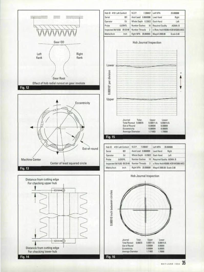
Gear ()O
Rightflank
Leftflank
(Gear Root
Effect of hob radial runout on gear involute------
Fig.12
Eccentric;ity
Out-af-round
Machine CenterCenter of least squared circle
Fig.13
Distance from cutting edgeFor c ecking upper 'hub
Distanc from cutting edgeFor check,ingllower hub
Fig.14
Probe
Scale O.4ll
Hob 10 4191 Left Contact
Serial 001
Operal0r Ed
N,D,P, 7,2.36461 Left NPA
Axial Lead 0,8661)000 lead Hand
20,000000
Right-
Whole Depth 0,23622 Gash Hand Left1-
O.07847L Number Gashes 10 Required Quality AGMA: B1---- ----
Inspected 04/15/93 09:20:48 NumberThreads 2 c:\Roto Hob\HBOO6.H08\MS009.MES
Inch Right NPA 20,000000 Me gnif 2000,00Metricllnch
Hob Journel Inspeetion
i,···,,,'''''''''''''''··''' ....''''''''·,, ..,,,,·,''',,·,,'''',,·,,,,· ,· ,,,..'1·.. · .. · .. ,·,""""'" .. ",·"·,",·"· .. ,, .. , .. ,",,·,,·,,·,,,·,,""', " ,..
1:'::::::::::::::::::::::.:::::::::::::::::::::::::::::::::::.::::::::::::::::::::::::::::i:::::::,:::::::::::::::::::::::::::::::::::::::::::::::::::::::::::::::::::::::::::::::::
Lower:;p .=-'". .. =::. ==1 • .. "· .. • .. ··, .. •••• .. ·%··· ..··· ..··, .. ·.. ·· ··••..•..• .i"·..·""'"·,,'''',..,''',..,·..·,··,,,·,..·,,, ,·,..,··..,,..,,·..' ,.,..' .1",..,,, , ,..,""',,.,,',, ..,,', ..,,..,.. ,,..,.. ''', ,'',''',' +
1 ••••••••••• :IIIIIII ••I•••II.m•••••••••••••••••••••••••••••••••••••••••••••••:1 t I
Upper I:•••..•:••..•..••••.••••••••••••~ ••··•··•·•.•••·••.••.••.....•••.••.•.1
1:::::::::::,:::::::::::::::::::::::::::::::::::::::::::::::::::::::::::::::::::::::::::::1!".", .......,...,. '''', ..,..,..,'''''''', ..,''', ..,''', ....,''''', ..,.,'''',....,',..,.1:
Journal Toler.iotal Runoul 0,00070Oul of RoundEccentricityAverage Diamets r
UpperO,OOOl1:A0,000040,000041.71883
lowero.oOO14:.A0,000090,000051.70886
Fig,15
Hob ID 4191 left Contact N,D,P, 7.23S46~ Left NPA 20.000000:.:.1
Serial 001 Axial Lead 0,8660000 Lead Hand RighI----------~-- ~ --------------1
Operator Ed Whole Depth 0.23ll22 Gash Hand Left--------------1
Probe Q,07814L Number Gashes Ia . Required Duality AGMA: B
2 c:\Roto HobIHBOOO,HOBIMSOO9,MESInspected 04115/93 09:20:48 Number Threads
Metric/InCh Inch Right NPA. 2Q,QOCOOO Magni! 2000.00 Scale 2.00
Hob Journal Inspection
UpperO,OOQll:AO.!Dll40000041.11883
Journal Toler.Total Runout 0,00010Out of Round~ccentricitvAverage Diameter
LowerO,00Q14:AO,ocoog0.00005IJ088Ii
Fig. 16

Hob face runout
Fig. 11
Left flank Right flank
Effect of hob face runout on gear involute
SurfaceVariation
Fig. 18
Hob ID 4191 left Contact N.D.P. 7.236467 LeftNPA 20.000000
Senal 001 Al:ial Lead 0.1m6OOOO Lead Hand RighI
Dperalllf :Ed Wll:ole Depth 0.23622 Gash Hand LehProbe n 07874l NumlMf Gashes 10 Required Qu!l", AGMA:B
Inspected 114115/93, 09:20:48 Number Threads c:lRoto HoblH BDOO.HOBIMSOOS.MESI Me1licllnch Inch Right NPA 20.000000 Meg"i! .2000.00 Scale O.4ll
H!obFace Inspection
Upper0.00006:1\0.l100050.000015.44237'
LowerD.00075:10.00D430.000302.42440
Fig.20
Face Toler.TDtIII Hunout 0.00030OutolAatEccentricityVertical PDsitJon
- -------------- -----
Fig. 19
36 GEAR TECHNOLOGY
----------------------------
IFigl.21
SurfaceVariation
Form
Evalusltion range'~~---- ------~
Fig. 23
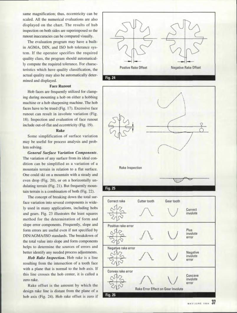
same magnification; thus, eccentricity can bescaled. AU the numerical evaluations are alsodisplayed all the chart. The results of hubinspection on both sides are superimposed so therunout inaccuracies can be compared visually.
The evaluation program may have a built-in AGMA, DIN, and ISO hob tolerance sys-tem. If the operator specifies the requiredqUality class, the program should automatical-ly compute the required tolerance.For charac-teristics which have quality classification, theactual quality may also be automatically deter-mined and displayed ..
Face RunoutHob faces are frequently utilized for clamp-
ing during mounting a hob on either a hobbingmachine or a hob sharpening machine. The hobfaces have to be trued (Fig. L7). Excessive facerunout call re ult in involute variation (Fig,18). Inspection and evaluation of face runout
include out-of-flat and eccentricity (Fig. 19).Rake
Some simplificati.on of surface variationmay be useful for process analysi and prob-lem solving.
Gene,.,al Surfacce Variation Components,The variation of any surface from its ideal con-dition can be simplified as a variation of amountainterrain in relation to a flat surface,One could ki ana mountain with a steady andeven drop (Fig. 20), or on a horizontally un-dulating terrain (Fig. 21). But frequently moun-tain terrain is acombination of both (Fig. 22).
The concept of breaking down the total sur-face variation into several components is wide-ly used in many applications, including hobsand gears. Fig. 23 illustrates the least squaresmethod for the determination of form andslope error components. Frequently. slope andform errors are useful even if not specified byDINIA:GMAlISO standards. The breakdown ofthe total value into slope and form componentshelps to determine the sources of errors andbetter identify any needed process adjustments.
Ho.b Rake Inspection .. Hob rake is a lineresulting from the intersection of a tooth facewith a plane that is normal to the hob axis. H'this tine crosses the hob center, it is cal1ed a
zero rake.Rake onset is the amount by which the
design rake line i distant from the plane of ahob axis (Fig. 24). Hob rake offset is zero if
Postive Rake Offset Negative Rake Offset
Fig. 24---
~V\
Ra,keInspection
Fig. 25
Correct rake Cutter tooth Gear tooth
~A V Corr,ect
involute
Ip~eerror
Plus
J\ V involut'B
qfJ error
N~tre".r/~ V NegativeinvoMeerror
I
IIConvex rake error
* /\ V Concaveinvoluteerror
Rake Error Effe,cton Gear Involute
Fig. 26
MAVIJUNE 1994 37
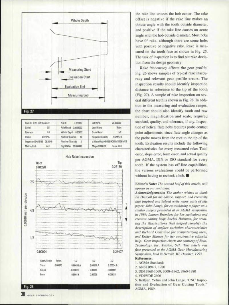
Whole Depth
Evaluation Stsrtr-__.--Evaluation End
Measuring End
-
Fig.21 ,
Magnd 2001.00 Scale 25.0
Hob In ~191left Contact
Senal 001
Operator Ed
Probe O.07874L
Inspected D4115193 09:20:48
Metrlcllncil Inch
N.D.P. 7.236467
Axial Lead 0.8660000
Whole Depth 0.23622 GashH8J1d _,LefI_.·_--I
Number Gashes '10 ReqUired Quality: AGMA: II_--II-
NumbetThreads 2 c;I.Roto Hob\llIlOO6.'HOIIIMSOO9 ..MES
Right NfA 2O.0C0J00
LeftNPA
laad Hand
20.0c0000
Right
Hob Rake Inspection
Root0.012201
Tip0.231891
! ····..···..·[··..i.! · ·.. ······!c···i.! ! ;I· • .. • .. 1,· .. ·:
~mli::iii:iii~i:ii:iiiiii::::::::::::~~~~+;. - , : 1~ 4/2 r;::;:~::::::::;:~:~~~:::::L:: :::::::~::::::::'::.: :::~:::::::::::':::::::::.q;',::1g t:~::::::~:::::~~:::::::::::::::::~:::~::::::::.:::::::~::::::~::::::::::::::::::~:::t: !~ i i ,
~ ,••.••••••••••••••••••••••• _ ••••••• r ~ ~ •••••••• l 1
latS:0:::~~~~1-0.00004 0.24407
GashJTooth foler. 1/2 412 7f2
Totll 0.00070 O.OOO38:A O.00037:A O.IlOO34:A
Slllcflll - 0.00028 -0.00016 -0.00007
form 0.00019 0.00028 0.000l8
fig. 28
38 GEAR TECHNOLOGY
the rake line cro ses the hob center. The rakeoffseti negative if the rake line make anobtuse angle with the tooth outside diameter,and positive if the rake line causes an acuteangle with the hob outside diameter. Most. hobhave 0° rake, although there ate some hobswith po itive or negative rake. Rake is mea-sured on the tooth face as hown in Fig. 25.The task of inspection is to find out rake devia-[ion from the design geometry.
Rake inaccuracy affects the gear profile.Fig. 26 shows samples of typical rake inaccu-racy and relevant gear profile errors. Theinspection result should identify inspectiondistance in reference to the tip of the tooth(Fig. 27). A ample of rake inspection on ev-eral different teem i hown in Fig. 28. In addi-lion 10 the mea uring and evaluation ranges,the chart should also identify tooth and rawnumber, magnification and scale, requiredstandard, quality .. and tolerance. if any. Inspec-tion of helical flute hobs requires probe contactpoint adjustments, since flute angle changes asthe probe moves from tile root to thetip of thetooth. Evaluation re. ults include the followingcharacteri tic for every measured rake: Totalerror, slope error, form error, and actual qualityper AGMA, DIN or ISO tandard for everytooth. If the sy tern has off-line capabilitie ,the various evaluations could be performedwithout having to recheck a hob .•
Editor's Note: The second hal] of this article. llliUappear in our next issue.Acknowledgements: The author wishes to thallkEd Driscoll for his tulvice, support, and creativitythat inspired and helped l+'I'ilemany parts of thlspaper; 10/m umge. for co-aulllOn'ng a paper on asimilar subject presented at an AGMA symposiumill 1989;' Lauren Bromberr for her meticulou: DIUI
cr;eatil'e editing help; Rachel Huisman; for creal-ing the illustration' that helped simplify thedescription of nlTface variation character! ticsand Richard Considine for computerizing them,and Esther Munsey [or her constructive editorialhelp. Gear inspection charts {Ire courtesy of Roto-Technology, Inc., Day toll, OH. This article wasfirst presented at the AGMA Gear ManufacturingSymposium, held in Detroir, Ml, October, 1993.Refeflence :I. AGMA Standards2. ANSI B94.7. 19803. DIN 3968-1069, 3000=1962, 3960-19804. VDINDE 26065. Kotlyar, Yefim and John Lange. "CNC Inspec-tion and Evaluation of Gear Cutting Tool. ..AGMA,.1989.

Diagrind SuperAbrasives Can
I Cur-e YOW" InternalDo you have news of employee pro- Grinding Problems.
motions, transfers or relocations you. Diagrind has developedwould like to share? Send your news diamond and borazonrelease to Gear Technology, People 011 super abrasive internalthe Move, P. O. Box 1426. E!k Grollegrinrung wheelswiththeYillage, /L, 60009,. or fax It to our Ihardness and toughness I
offices at {708~ 437-6618, Note: .5to- Ito grind marenals thatries to appear In the July/August ISsue I ordinary abrasives can'tmust be receive.dill ~ur ollic~s by grind efficiently. Combined with ourMay 10. They Will be mel uded In the special bonding processes and superissue on a space-available basis. Items stitffcarbide shank. Diagrlnd grind-reaching us past this deadline will ing wheels last longer and workappear in the Sept.lOct, issue, more efficiently than many other
grinding wheels. Standard andspecial wheels are available from
. ruling \VbeelsSuper Abrasive r;JOb&/F r Super Toug
I 0
ATA Gears, Inc.Cleveland, OH. Mr. RanDO Ellan-
der has been named president andMr. Thad N. Schott has beennamedvice-president of North Americanoperations of AT A Gears, Inc.,Cleveland, OH. AT A Gears, Inc., isthe U.S. subsidiary of ATA Osakey-htO of Finland, a manufacturer of spi-ral bevel gears.
T.S. AnoysHouston, TX. Mr. Michael Likos
has been promoted to co-generalmanager of T. S. Alloys of Houston,TX, where he will report to TroyMarshall. vice president. of Ave taSheffield, Inc.
T. S. Alloys, a stainless steel andaluminum ervice center, is whollyowned by Avesta Sheffield. whoseworld headquarters are in Schaum-burg, [L. T. S.. Alloys' regional mar-keting area includes Texas. Ar-kansas, Louisiana, New Mexico, Ari-zona and Mexico.
Sins ofOmis ion: A credit for the article"Investigation of Surface Layer andWear Behavior of Nitrided Gear Drives,"which appeared in our last issue wasomitted. Our thanks 10 Kolene® Corpora-tion, Detroit. Ml. who brought the articleto our attention and provided technicalassistance in its preparation.
We are looldng for some coveT,If you have a phQtoof V.&ft being m........'..!.
ground. shaped, heat tnated, etc. that'think might look great on the nellt issueCear Tl!chnology please send it for y,eview
Cear Tec:hnologyArt Dept.IltOl' L'Unt ,Ave.ElkCrove Village. IL.60001
Internal Medicin,eI
1/32 to 3 inch. Form wheelscan be custom manu-fuctured
'CIRCL.E A-8 'tin READER REPLY CARD
MAYlJlJNE 1994 39

Gear Metrology Standardsand IS,IOI 9'0001
"Viewpoint" provides an:olPp,ortuniityfor read,elll'sto ;resp,ond to artlcles that :,appear lin our IP,ages.lettersshould be address to VieW'-IPoi'nl. G;ea!rTechnology. P. O.IBox11426. Elilk 'GroveViUage.Ill" 60009 or faxed to 1-108..431-6618. Lettarsaebmlttad 10'
"Viewpoint," became theplmperty ·of Gear Technology;Names w:ill be wiithheld uponrequest, howeve'r, no anony-mous letters wii IIII be pub-lished. We reserve the ri'ghl to,edit leHeirs in the interest ofspace, Opinions expressed bycontributors are Inot necessalli'-lily those olf th,e editor or theIPub~I'ishiingstaft.
40 GEAR TECHNOLOGY
I noted with interest the beginningof Gear Technology' s three-partserie on ISO 9000 certification. Ialso recently attended Brown &Sharpe' !Leitz gear metrology , emi-nar. Both events cau ed me to mileand reflect.
For the his! 40 or more years, [have been hearingaboul thedeplorable condition of the Americangear industry. J heard it again at theBrown & Sharpe/Leitz eminar,
Amy Zuckerman makes anextremely important. distinction in herarticle on ISO 9000. She notes thatthe emphasis is upon '"quality assur-mice" not "product assurance" Shenotes that it is possible to make avery poor product very efficientlyand be ISO 9000 certified.
WiIllhat help the gear indu try?Will it help any industry? WHI itstrengthen or improve our position inworld trade?
One of the things to be gleanedfrom the Brown & Sharpe/Leitzmetrology seminar i thaI there aretandard measurement gaages which
most industrialized nation use. Themore frigbtening fact gleaned fromthe seminar is that gear mea urementequipmentand it data have neverbeen traceable to these standards.
information, the players are li ted as:AS ME. AGMA. Penn State Universi-ty, 'the National Bureau of Standardsand Technology (formerly NSB, nowN1ST), and the Do.E Y-12 Plant.
Having a single traceable standardfor gear metrology may go furthertoward establishing the viability ofthe American gear industry than any-thing ISO 9001) may hope to offer, Aparamount. condition at ISO 9000 is"traceabiliry," but ISO. 9000 certifiesthe traceability of the proces e , notthe product.
The gear industry may need toevaluate carefully the "promi e" ofISO 9000. The gear industry MUSTattain 11 world-verifiable and trace-able metrology for its product if itever hopes to eliminate its"deplorable condition."
[I should be noted that this ge.armetrology investigation began withthe "Leitz" last year, It appears thatthis may be where the money takenfrom [NFAC is now being directed,
I still question the ultimate valueof dependency upon nadonal govern-ments to establish the direction andperformance of industry.
Clem Miller,President, Miller & A soeiates
Is it a wonder that the American Crown Point. INgear ,industry has been in a "deplor-able condition" or a state of confusion?
I have learned of a program caned"A National Policy for Gear Metrolo-gy from NIST and 00- ." For genera]


WHAT AIKES ALIL THESE ACHIINES, SOACCURATE, PRODUCTIVE, AND VERSATILE
OR
.,•
ACCURATE· To wi1hin f .0001· of programmed dimen·sion. with r,epesl a.ccuracy 10with'n ,00005', Edra. preci·sion roller bearing ways. pre-loaded roller screws andoptical linear encoders, as well as superior design andconstruction, give the FORMASTER the ability to holdinspection gage accuracy,
PRODUCTfVE . No templates or Special diamond rolls areneeded, so lead times and tooling inventOries are reduced,Mostlorms can be programmed and dressed in, ready togrind in 30 to 45 minutes,Refreshing the lorm betweengrinding passes, is accomplished in seconds,
VERSATILE - Can be used wilhsingle point diamonds orwith optional rota/y diamond wheel attachmenl. Nearly any'form can be dressed Quickly, easily and accurately,
[)U RAB LE·, Hard seals are closely fitted and are airpurged to totally exclude contamination, Sealed servomotors, automatic lubrication and totally enclosed enood,ers minimize dowotLme and ensure long service me,
Tel: (810) 349-.2644 J Fax: (B10) 349·1440For information or to arrange a demonstration
eNC GRillNDING WIHEEL PROFILERMADE tN U,S,A
'CIRC'L.E A·12 on FlEADER IREPL.Y CA'RD
TRU,E DIMENSI:ON ,GEAR INSPECTION
Gage, Division
5
Provides actual everball/pin measure-ment of any helicalor spur gear Of
spline without theneed of costlysetting masters,
Provides vital S.P.C..information.
, CAPACITY:9" O.D.,8" I.D.
CIRCLE A.;35 on READER IREPLY CA'RO
85,1101'110PIKE. CINCINNATI, mUD 45245. P,H, (513) 152-6000· FAX(513) 152-5599
42, G EA R TeCHNO LO GV
Designing Hardened &Ground Spur Gears to
Operate WithIMiinimlUlm Nois,e
When designing hardened andground spur gears to operate withminimum noise. what are the para-meters to be considered? Shouldtip andlor root relief be applied to'both wheel and pinion or on~y toone member? When pinions areenlarged. and the wheel reduced.should tip, relief be applied? Whatarethe effects on strength, wearand noise? For given ratios wIthenlarged pinions and reducedwheels, how can the gear set sizesbe checked or adjust,ed to ensurethat tbe best combination has beenaehieved?
This is a complex question, requir-ing consideration of both rating andnoise. Three of our technical. editorshave reflected on the subject.
Robert E. Smith replies: The pri-mary consideration for the minimiza-
Robert E. SmithRobert Enichello
Don McVittiie
root relief to allow for tooth deflec-tions such that they are true involuteswhen loaded.
Even with profile modifications,there are a couple of other subtleproblems that can cause noise that iobjectionable to the human ear. Manytimes unground gears call be lessaccurate, yet sound more pleasing tothe ear than precisely ground gears.This is because random spacingerrors and runout or accumulatedpitch errors cause a masking noisethat tends to cover up the pure tonesand harmonics that ave generated bythe me h frequeneie . The accumulat-ed pitch errors can cause sidebands ofmesh frequency that appear like a"white noise" floor level in the spec-trum. When grinding gears, it is notunusual for this background noise tobe much lower than the gear mesh
tion of noise is to reduce tooth-to- frequencies. This makes the pure tonetooth transmission error under theloaded operating conditions, Thismeans making the teeth as conjugatea possible under load; a true involuterunning with a true involute. ForIighdy loaded gears, this means mak-ing lhe involutes as perfect as possi-ble. For gears operating under signifi-cant loads, the teeth can have profilemodifications in the form of tip or
effects :more objectionable to thehuman ear, even though the overalldbA level may be the same.
The second subtlety comes from aphenomenon called "ghost harmon-ics." This is usually a high pitchednoise that is caused by waviness inthe profile or lead of the teeth. Theewaves are commonly called undula-tions. The critical ones lie parallel to
SHO'PFLOOR.Address yOu.r Igea,ring ques-tions to our panel 01 experts.Write to them care' of S'holpFlo,or. G,eal' Technollogy. IP. O.Bo,x 1426. IElik 'Grove' Villag;e,IL 160009,or call ,our editoria,llstaff at (708) 437-6604.
Robert E.. :Smithi.f tile principal in R. E.Smith & Co.• Inc.. gear con-sultants ill; Rochester. NY.
Robert Err;ich'BlI'ois the principal ill GEAR-TECH. a gear consultingfirm ir, AlballY, CA.
Don M'cVittieis president of Gear Engi-neers ..lnc., Seattle WA,
M"'VIJUNE 199. 43,

the instantaneous line of contact,They are caused by the final drivegears of the work spindle all the geargenerating machine. There will be anintegernumber of waves in one rev-olution around the gear being manu-factured, and the number will be thesame as in the final work spindledrive gear. The result ean be a verysmall waviness in the involute pro-file and/or lead charts and is fre-quently ignored ill the assessment ofthese charts. The waviness can oftenbe smaller in amplitude than ..0001.",yet cause significant noise. Howev-er, these peaks can be detected bysingle flank transmission error test-ing, as well as by noise analysis
through the use of an FFT analyzer.If you know the number of teeth inthe final work spindle drive gear, youcan predict where the peaks will befound in the spectrum.
A good practical guide to the.application of profile modificationmay be found in the Gear Hand-book, McGraw-Hill, 1962, Chapter 5,pp. 22 and 23. by P. Dean. He states:"Ill general, gear teeth which carry aload in excess of 2,'000 lbs. per inchof face width for more than a millioncycles should be modified. Thoseunder ],000 lbs, per inch of face donot generally require modification."Formulas for the amount of tip reliefon the driving and. driven gears are
TilPi reliiet on dri,ven gear prevents linterference.
fig. 1 - Interference occuning at last point Df contact (Point AI.- -
Dr;;;---"""lJine ofAction
lipl relief on dri,ving Igear prevents interference.
Driven
~
Line lofAction
44· GEAR TECHNOLOGY
Fig. 2 -Interference cmcurring at last point of contact (Point D).
given in this reference. Another ref-erence is the Handbook of PracticalGear Design, McGraw-Hill, 1984,by Dudley. This contains several sec-tions on profile modification andgenerally indicates putting tip reliefon both members .
From a noise reduction standpoint,the best advice is not to use moreprofile modification than is absolute-ly necessary. It can cause a rapid Jossof profile contact ratio and conjuga-cy. Start out with little or none inorder 1:0 meet. the noise requirementsand then life test to see if the partswill survive. Many people start withtoo much modification, in anticipa-tion of tooth failure, and then wonderwhy the gears are noisy.
Bob Errichello replies: One of themost important decisions a geardesigner makes is selecting the nurn-ber of teeth in the pinion. There is apreferred number that provides agood balance between pitting resis-tance, bending strengthand scuffingresistance. See AGMA 901-A92 foran algorithm for calculating the pre-ferred number of teeth.
Profile sbifl (enlarging/reducing)is used to
• Prevent undercut• Bala.nce specific sliding• Balance flash temperature• Balance bending fatigue life• Avoid narrow top lands.
The profile shift should be largeenough to avoid undercut and smallenough to avoid narrow top lands. Ingeneral, the profile shifts for balancedspecific sliding, balanced flash tem-perature and balanced bending fatigueare different, but nearly the same ifthepinion has the preferrednumber ofteeth (see AGMA 901-A92).
Profile modification is used tominimize the detrimental effects oftooth deflections, assembly toler-ances and tooth variations, Properprofile modlfication increases loadcapacity and reducesnoise,
Fig. 1 shows the interference that
occurs at. the first point of contact(Point A) with unmodified involutes,The interference i due to deflectionsof the pair of teeth in contact at PointC, which lengthen the ba e pitch ofthe driven gear and shorten the basepitch of the driver. The interferencecan be eliminated by profile modifi-cation that removes material fromthe tip of the driven gear (shadedzone in Fig. 1).
Fig. 2 shows interference at thelast point of contact (Point D) withunmodified involutes, The interfer-ence is due to defections of the pairof teeth at Point B. which lengthenthe base pitch of the driving gear andshorten the base pitch of the drivengear. The inrerference can be elimi-nated by profile modification that
removes materia] from the tip of thedriving gear (shaded zone in Fig ..2).
Experience showsthat the profilemodification should be larger at thefirst point of contact than at the lastpoint of contact. Generally the firstpo.int of contact is more criticalbecause the oil film is not well devel-oped and the frictional forces arehigher as the gear teeth approach thepitch point rather than recede from it.
With speed reducers, the firstpoint of contact is at the start ofactive profile (SAP) of the pinionteeth where they are especially sus-ceptible to pitting.
With speed increasers, the firstpoint of contact is at the tip of the pin-ion teeth and the SAP of the gearteeth where both members areespe-dally susceptible to scuffing.
With regard to the kinematics ofthe gears, it doe nat matter whetherthe material is removed in the form oftip relief or root relief. However, theinvolute profile is more difficult tocontrol near the base circle becausethe curvature is rapidly changing.Therefore, tip relief is generally pre-ferred over root relief for ease of
manufacturing.Don McVittie replies: The parame-
tersto be considered in determiningthe am aunt of profile shiftand thedistribution of profile shift betweengear and pinion are best covered inAGMA 901-A92, Rational Proce-dure for the Design oj Minimum Vol-ume Gears, Annex A. The MaagGear Book also has good basic infor-mation on why and how. Both areavailable from J\:GMA ..
Parameters which reduce noise areusually:
• High accuracy, particularlysmall adjacent pitch variatlon, goodhelix (lead) matching and convexrather than concave involute profiledeviation.
• High transverse contact ratio. Thefollowing increase it:
• Low operating pressure angles• High numbers of teeth• Long (extra depth) teeth• High axial contact ratio - 2.0 or
more. It is increased by:• Higher helix: angles• Finer pitches - smaller modules• Wider face width may be bene fi-
cial, but can cause problems withlubrication and load distribution.
• Some engineers strive for integervalues of axial contact ratio, be-lieving that this reduces the vari-ation in stiffness caused by thevariable length of the helicallines of contact. This is probablymost important with axial con-tact ratios less than 2.0.
The optimum design varies,depending on the application. FQrexample, the best practice for indus-trial conveyor drives is much differ-ent from that for marine reductiongears or automotive gears. Usuallysame compromise is required be-tween optimum design for bendingstrength and optimum design for min-imum noise. An optimum design forpitting resistance can be a good start-ing point. The vibration response ofthe housing can also be important. A
Light weight housing with many lownatural resonance frequencies willrespond to excitations from the gearteeth which wouldn't be important ina heavier housing with higher naturalresonant frequencies.
Tip relief call be applied as tip androot relief on the pinion or as tiprelief on both gear and pinion, Withthe pinion driving, the required geartip relief or pinion root relief is usual-ly about 113 more than the requiredpinion tip relief. It is hard to manu-facture accurate pinion root relief ifthe pinion's start of active profile isnear the base circle. Sometimes it'simpractical to achieve the requiredroot relief in a few degrees of ronnear the pinion base circle, so bothparts are tip relieved.
In the U.S., stock hobs used to befurnish with a "ramp," an area ofhigher pressure angle near the footof the bob tooth, which cut tip rehefin both gear and pinion. The amountof tip relief on the part varied withthe number of teeth and the profileshift. so the effect was hard to con-troL Most manufacturers nowachieve tip and root relief by grind-ing or by shaving with speciallydesigned cutters.
For a discussion of how much tiprelief to allow and where to startmodification on the profile, see Dud-ley's Handbook of Practical GearDesign, pages 8.,]2 through 8.21.
Properly designed and manufac-tured tip and root relief on spur gearsor tip. root and end relief on helicalgears reduce dynamic load by assur-ing smooth meshing as the teethengage and disengage at the ends ofthe lines of contact. Reduction of thedynamic load is benefiuial forstrength, pitting resistance and noise ..It also encourages the formation of anoil film between the teeth whichreduces the tendency toward micro-pitting and abrasive wear. The bene-fits apply to all heavily loaded gearswith or without profile shift. •
MAY/JUNE. 1994 145
SAVE WARRANTY COSTS WITH
DiamondBlack®
•Ic to a n
BENEFITS:
93-95Rc HARDNESS
LOW TEMPERATUREApplied at under 250°F
AMORPHOUS STRUCTUREResists chipping.
cracking & Peeling
HIGH ADHESIONWill not transfer
AFFINITY FORLUBRICANTS
CHEMICAL RESISTANTImpervious to most harsh
chemicals. acids and bases
UNIFORMITYSurface replication with
no build up
TEMPERATURE RESISTANTTO 2282°F
EXTREMELY THIN(80 Millionths)
US & FOREIGN PATENTED
DiamoDd Blact™ coatedgean have provided 7 timesthe gear Ufeft. uncoated.
DIAMOND BLACKTECHNOLOGIES, INC.
P. O. Box 190100 Somerset Drive
Conover. NC 28613-01901-800-388-9968
FAX 704-322-4636
CI,RCLIE A·26 on IREADER REPI.V CARD'
46 GEAR TECHNOLOGY
gMAY8~1lMetal. Powder Industries Federation,American Powder Metallurgy Insti-nne. l994 International Conference &Exhibition on Powder Metallurgy &Particulate Materials, Toronto. ana-da. Technical sessions and papers Oil
powder metallurgy research and man-ufacturing, For more information, fax(609) 987-8523.
MAY 9-10Penn Slate University. AdvancedGear Manufacturing Sympoium.Win cover carrentgear manufactur-ing technology and re eaech-relatedis ues. For more information, callGreg Johnson at (814) 865-8207.
MAY 10Polycrystalline Product As celation."Increasing Productivity with Poly-crystalline Diamond and CBN Prod-ucts." Sheraton Suite Hotel, ElkGrove Village (Chicago). IL Pres en-tations on high speed machining ofcast iron with PCBNtooh. peDbasics, rotary tOOUDg with PCD, CVDcutting tools and more. For moreinformation. call (614) 798~2253 orfax. (,614) 798-2255.
MAY 15-17Gear Research Institute, IatemationalConference on Inductiea-HardenedGear . Indi anapolis. IN. ContactSharon Shaefer. GRl, (708) 241-0660or fax (708) 241-0662.
MAY 16-20AGMA Training School. for GearManufacturing. Daley College,Chicago, IL. For more information
call AGMA headquarters at (703)684-021 [ 01" fax (703) 684-0242.
MAY 24-25AGMA Technical Education Seminar,"Gear Failure Analy is." Hilton Com-monwealth HOlel, Florence, KY(Cincinnati). Will cover overload.bending fatigue. Hertzian fatigue,cracking and gear failure photogra-phy. For more information, can (703)684-02] 1 or fax (703) '684-0242
JUNE.I3-lSUniversity of Cincianat], Center forIndustrial Heal Treating Processes.Royce Hotel-Metropolitan Airport,Detroit, ML For more information,call (513) 556-2709 or 2710 or fax(513) 556-3390.
SEPT 7-9UK Gear Metrology Lab, Universityof Newcastle. Britsh Gear Associa-tion, 1994 Imernational Gearing Con-ference. University of Newcastle.Themes include research, design,components, materials. productionand industrial practice. For moreinformation. contact Jane WaUace,Dept, of Mechanical Bng., Stephen-son Building, University of Newcas-tle. Newcastle lipan Tyne, England.NEI7RU.
S.EPT. 14-16Ohio State University. Short Cour eon 'Gear Noise. Robinson Laboratory,OSU campus, Lectures. case hi. to-ries, lab demos. For more informa-tion, contact Carol. Bird at OSU,(614) 292-3204.

LITERATURE MART--------
CarbideGrlndllnsConsistencyThat'"ReallyCooll
Cooler Carbide GrindingErnst Winter & Son, Inc.,introduces its Rcptilla n.1grinding wheel, offering supe-rior consistency for greaterprocess control, less mainte-nance and less downtime inthe toolroom. Its uniquebonds provide cooler grindingand longer life for dry grind-ing carbide on standard tooland cutter grinders. Specs onavailable wheels included illnew flyer.Ernst Winter & Son. Inc.Call (803) 834·4145.CIRCLE READER SERVICE '13
Sffirp Mirds
Broaching TechnologyDetroit Broach Companyoffers a brochure explainingefforts to provide the late tbroaching technology al themost competitive prices. Cer-tified by the leading namesin manufacturing, DetroitBroach has a commitment 10quality products and service;desi gni ng, manufacturing,resharpening, remanufactur-ing, troubleshooting or con-sulting. Please send forFREE brochure or call (800)383-6978.cmCLlE READER SE:RVICEf 17
~SPCWa-bt,,1i:Jru!PmwloQwWtySolubonaf1a\\bId.a...M..n~
@1oIETIISm!E .-_ ...__ ...-.
Optimized IGearCheckjngBla.ck. & Decker drops gaugeR&R from 87% to below19%. Their Metrscope TQCGear Chek appf ication,designed to complementMetrscope's SPC Worksta-tion,TM optimizes gear check-ing, and improves quality andspeed of production 'Up to95%. Metr cope's Sf'C Work-stations and TQM software:Call (803) 458-3232 Fax:(803) 234-4852.
CIRCUE READER SERVICE #14
In~~
On-The·Job Training'lor Entry-Level Heat Treaters
F.,o_"_,,...,.. .....~1fIICI' __ .~_~
....--- ~---__ l!II!!JIt .. -. daro\~
.,,.. .. n., ....'_n_._~NG._. _--'I'IW"I!..,....-- ........ _o.,.n..:!=:::",.:.c:.:.:-.:=._1,...,. ....--.._ a ....a .......lIIIiIIaI ~ __ ,(M.~]~.ID!,.
Video-Train Heat TreatersIntroducing On-the-Job Train-ing for Entry-Level HeatTreaters. A heat treating shopcan be a challenging place forthe novice. This 5-videotapeseries from ASM Internationalcovers the basics in real-worldterms. They're easy to under-stand and only $49.95 each.To order, call Carol at1·800·336·5~52,. ext. ,632
CIRCLE READER SERVICE j 37
The Complete IGearBookGear Geometry & AppliedTheory, by Faydor I.... Litvin,covers the modern theory ofgearing, geometry. design andcomputerized simulation ofmeshing and contact foralmost all gears; the geometryfor face-gear drives, doublecircular-arc helical gears;C ,C applications and newapproaches for tool design,Prentice-Hall, 1994. $72.00.To order call (800) 947·7700.
THE MODEl.. EC-3500
IGea'rHoning Ma.c'hineThe new Sunnen EC-3500Honing Machine is a perfectchoice for sizing and finishingbores in gears of an types. andsizes. It can hone gears andother parts twice as fast asprevious honing machineswith better bore geometry,including excellent bore-to-face squareness, Send for bro-chure to Tom Deehr, SunnenProducts Co .• 7910 Manches-ter, St. Louis, MO, 63143. Ph:(800) 325-3670.
CIRCLE READER SER,VICE # 1'91
Micro,pulse®Contour Hardening, Inc,defines a good gear as a three-legged stool - that is, a gearthat equally possesses totalgear strength, proper hardnessand microstructure, and dimen-sional stability. Only MJCRO-PULSE@ can satisfy all threelegs of the mechanical proper-ties too], simultaneously andwijhout oompromise. Call us at(317) 876-1530 for ApplicationDevelopment, Contract Pro-cessing in OUI plant or a com-plete MI ROPULSE System.CIRCLE REA'DER SERVICE 1116
IFreeNASA. literatureCOSMIC. NASA's ComputerSoftware Technology TransferCenter, offers a free brochuredescribing 15 computer pro-grams in the general area ofStructural Analysis that. weredeveloped for internal. use byNASA. These programs aremade available in source codeform for reuse within the U.S.Contact. COSMIC, 382 EastBroad Street, Athens, GA.30602-4272. Ph: (706) 542-3265. Fax. (706) 542-4807.
MAYIJUNE 19H 47

SERVICE------
Contour InductilonIHlardening Specialists
,$pUT, helical and bevel gearsOur gear hardening equipmentincludes 3 NATCO submerqedprocess machines and 4 AJAXCN'C-controUed gear scanningmachines. We can also tool tomeet any production need.Write for a free brochure.
Ameriican Metal Treating Company1043 Ea5t 62nd Stre etCleveland,OH 44103
(216) 431-449'2IFax: (21:6) 431-1508
CIRCLE A·34 on READER REPLY CARD
GEAR TOOTHGRINmNIG SERVICES
• east eJfectiv,e gear tooth grindingspecialists
'. Gealr manufacturers are our on!lycustomers
-Prototype and production quantities- Capacity to .27.5"P.D., 3.5, n P.- Able to match delivery to your
requirements- All service to AGMA standards with
Certmed Gear Inspection Equipment PRODUCTION HOB SHARPENINGELTECH Inc. ~9841 York Alpha Drive ~N. Royalton. OH 44133Phone: (216) 582-8195Fax: (216) 582-8226
PRO-G EAR COMPANY, liNe.23 Dick Road Depew, N'Vl4043
Phone [7161684-3811Fax (71'6)684-7717
HOB SHARPENERS• Remanufacturing/Rebuilding
• Programmable Control Retrofits• Updated Hydraulic Systems
• Field Service Repairs
GEAR INSPECTIO EQUIPMENT• CalibrationJCertification
• Field Service Repairs
CIRCLE ,A·31 on READER REPU:' CARD'
EQUIPl\t1ENT
COMPUTERIZED,GEAR MEASURI'NG
".~"~...~U--\. Comp,osite~ Gear Analyzer®Now 8vai I'able'. specificallv designed
to, i8ccur,ate1v aequi re signal fromFeHows Rillil Liners,
• Runs the' actual Measurement• Produces a high resolutiongra ph.• Analyzes the acquired data.• Calculations ,including:
,/ Total composite variation,./' Maximum tecth-tc-tcoth variation./ Average and Maximum/minimum
center distance,,.I Pitch ,lin e runout
THE BEST JUST GOT BETTERINVOLUTE' LEAD -INDEX' COMPOSITE
HELP WANTEDDIJIECJ'OR OF SALES AND IIfARKETr G:$200.000 PX8. Gear MachineI)'l\IUlNAGER OF MA liF!\Cl:URING GINEER-ING: S60K. Gear DesigI1 a Plus.MANUFACTURING :ENGINEER: $45.000Q ALlIT mREcroR: S60,OOO+.20 in depanmenl.Automotive Supplier.Contact AIIII Hunsucker Godwin. &cel Associates.P.o. Box 520, Cordova. T:-l 38088 orCall (901) 757·9600 or FAX (901) 754·2896.
Midwest located producer of precision and eornmer-clal gears, see .....machined parts. and precisionmachined components has servera.1 key openings.Contaei' us to e..plQre 'Opemtlons Man - ger. QualityManager, Gear Design Eng'ln~', Industrial/Pro-cess Engineer. and CNC Supervisor opportunitIes .Write or eall: Howard 'Ml.leller.·mfgtSearch roc..325 E. Eisenhower Drive, Suite 106, Dept 04150T.Ann Arbor, MI 48108. (800) 762·7976.
Rates: Line Classified - $37.50 per line. 8 lines per inch. $300 minimum. Classified Display - per inch (3" min.): IX - $.170, JX - $1.60, 6X -$150. Type will be set to advertiser's layout, or Gear Technology will set type a! no extra charge.P,ayment: Full payment must accompany classified ads. Send check or Visa/MastecCard/American Express number and expiration date to: GearTechnology, P. O. Box 1426. Elk Grove Village. It 60009. Agency Commission: No agency commission on classifieds, Materials Deadline: Adsmust be received by the 25th of the month, two months prior to publication. Acceptance: Publisher reserves the right to accept or reject, classifiedadvertisements at his discretion.
,48 !lEAR TECHNOLO(lV

CALL 1·BOO·45HI166 FOR DETAilS OR FAX US AT 708·431·6618 ..OVERSEAS BUYERS CALL 001-708·431-6604 ..
BON'T WAIT. TO 'GIET THE MOST SAV~INIGS,SIGN UP BEFORIE AUGUST 10..
Direct them right to your door with a listing orVJ.P.S,.* ad in G'ear Technology's AnnualBuye'rs Guide in our Nov/Dec issue.
*" Ve'ry Impolrtant Product or Service
Don't get lost in the crowd in some gigantic directory that coversthe entire machine tool universe. Gear TechnDlogy readers wantand need your qear-relatad products and services. Tell themwhere to go to 9,8tthem.
It's EASY.Fill out a simple form and send it with your payment to us.We do the rest.
It's AFFORDABLE.You can be in this important industry directory for as littleas $2501.10% discount for orders placed before August 10.
It's EVEN BETTER FOR DISPLAY ADVERTISERS.Display advertisers in the Nov/Dec issue getFREELISTINGS and up to 15% off on additional listings.
It's EFFECTIVE.The Buyers Guide is an important reference tool that ourreaders refer to again and again. Your ad in its pagesworks all year long.
Geal Technolo'gy~sAnnual Buyers
Guide

~----onalBroach works rlyour' tough gear ap'p,l·
...to help YQu ring up more profits tbrou b greaterNational Broach, an industry leader in
the gear finishing arena, now offers acompfete line of gear manufacturingmachines and tools,
From hobbing through honin9'. usinglatest cell manufacturing
techniques, you can now eff·identmachine blanks into finished ears onRed iRing machines, You'll. Iso add theconvenience of a single-source for gearmachines to the long:' of traditionalRed Ring advanta
As w)h our quality-award-winninggear fh1ishing tools, the full Red Ringllin of machines is backed by ourcommitment to total customer support.To let us show you, just give us a ring ..
GEARING THE WORLD FOR TOMORROW
. ree Mile Road • Macomb, Michigan 48044 • Phone: 313-263-0100 • fax.: 3 t 3-263-4511CIRCLE A-30 on READER REPLY CARD