i. Tsuji, k. kawasaki and H. Gunbara - Gear Technology · Next, the real tooth surfaces of the gear...
7
Printed with permission of the copyright holder, the American Gear Manufacturers Association, 1001 N. Fairfax Street, Fifth Floor, Alexandria, VA 22314-1587. Statements presented in this paper are those of the author(s) and may not represent the position or opinion of the American Gear Manufacturers Association. Introduction Bevel gears are used to transmit power and motion between the intersecting axes of two shafts, most often mounted on shafts 90° apart. They may have straight, Zerol, spiral or skew teeth (Refs. 1–4), and are common in gear transmissions (Ref. 5). The transmission of straight bevel gears is regarded as a par- ticular case of skew bevel gears (Ref. 6) in that their contact ratio is larger than that of straight bevel gears and skew bevel gears have oblique teeth. Skew bevel gears are typically used in power generation plants and are quite large. In recent years these mostly aging plants have been undergoing extensive retrofitting and so it has often become necessary to replace the skew bevel gears used in them. In some cases, where only the pinion member is changed, it then becomes necessary to manufacture a new pinion that per- forms well with the existing gear member. It is now possible to machine these gears’ complicated tooth surface due to the development of multi-axis control and multi- tasking machine tools (Refs. 7–8). Therefore, high-precision machining of large-sized, skew bevel gears has become com- monplace. Proposed here is a method for manufacturing new pinion mates for large-sized, skew bevel gears using multi-axis control and multitasking machine tools. This manufacturing method has the dual advantages of arbitrary modification of the tooth surface and of machining the part without the tooth surface (Ref. 9). To begin, understand that the tooth surface forms of skew bevel gears are modeled mathematically. Next, the real tooth surfaces of the gear member are measured using a coordinate measur- ing machine (CMM), and the deviations between the real and theoretical tooth surface forms are formalized using the mea- sured coordinates. It is now possible to analyze the tooth contact pattern and transmission errors of the skew bevel gears while addressing the deviations of the real and theoretical tooth surface forms by expressing the deviations as polynomial equations. The components of the deviations of tooth surface forms cor- responding to the distortions of heat treatment and lapping, etc., are used because the motion concept can be implemented on the multitasking machine. Further, deviations of the tooth surface forms of the gear member can be reflected in the analysis of the tooth contact pattern and transmission errors, and the tooth surface form of the pinion member that has good performance mating with the existing gear member is determined. Finally, the pinion mem- ber is manufactured by a swarf cutting that is machined using the side of the end mill of a multi-axis control and multitasking machine tool. Afterward, the real tooth surfaces of the manu- factured pinion member are measured using a CMM and the tooth surface form errors are detected. Although the tooth sur- face form errors were especially large on the coast-side, they are in fact minimal on the drive-side. In addition, the tooth contact pattern of the manufactured pinion member and the provid- ed original gear member were compared with the results from tooth contact analysis (TCA), and there was good agreement. Tooth Surfaces of Skew Bevel Gears As mentioned, the tooth surface forms of skew bevel gears are modeled mathematically. In general, the geometry of the skew bevel gears is achieved by considering the complementary crown gear as the theoretical generating tool. Therefore, the tooth surface form of the complementary crown gear is consid- ered first. The number of teeth of the complementary crown gear is rep- resented by: (1) z c = z p = z g sin λ p0 sin λ g0 where: z c is number of teeth of complementary crown gear z p is number of teeth of the pinion z g is number of teeth of the gear λ p0 is pitch cone angles of the pinion λ g0 is pitch cone angles of the gear Figure 1 shows the tooth surface form of the complementary crown gear assuming to be straight bevel gears with depth-wise tooth taper. O-xyz is the coordinate system fixed to the crown gear and the z axis is the crown gear axis of rotation. Point P is a reference point at which tooth surfaces mesh with each other and is defined in the center of the tooth surface. The circular arcs with large radii of curvatures are defined both in xz and xy planes; the xz and xy planes correspond to the sections of the tooth profile and tooth trace of the tooth surface, respectively. Producing Large-Sized, Skew Bevel Gear Pinion Using Multi-Axis Control and Multi-Tasking Machine Tool I. Tsuji, K. Kawasaki and H. Gunbara This paper proposes a method for the manufacture of a replacement pinion for an existing, large-sized skew bevel gear using multi-axis control and multitasking machine tool. 58 GEAR TECHNOLOGY | March/April 2013 [www.geartechnology.com] technical
Transcript of i. Tsuji, k. kawasaki and H. Gunbara - Gear Technology · Next, the real tooth surfaces of the gear...
Printed with permission of the copyright holder, the American Gear Manufacturers Association, 1001 N. Fairfax Street, Fifth Floor, Alexandria, VA 22314-1587. Statements presented in this paper are those of the author(s) and may not represent the position or opinion of the American Gear Manufacturers Association.
IntroductionBevel gears are used to transmit power and motion between the intersecting axes of two shafts, most often mounted on shafts 90° apart. They may have straight, Zerol, spiral or skew teeth (Refs. 1–4), and are common in gear transmissions (Ref. 5).
The transmission of straight bevel gears is regarded as a par-ticular case of skew bevel gears (Ref. 6) in that their contact ratio is larger than that of straight bevel gears and skew bevel gears have oblique teeth.
Skew bevel gears are typically used in power generation plants and are quite large. In recent years these mostly aging plants have been undergoing extensive retrofitting and so it has often become necessary to replace the skew bevel gears used in them. In some cases, where only the pinion member is changed, it then becomes necessary to manufacture a new pinion that per-forms well with the existing gear member.
It is now possible to machine these gears’ complicated tooth surface due to the development of multi-axis control and multi-tasking machine tools (Refs. 7–8). Therefore, high-precision machining of large-sized, skew bevel gears has become com-monplace.
Proposed here is a method for manufacturing new pinion mates for large-sized, skew bevel gears using multi-axis control and multitasking machine tools. This manufacturing method has the dual advantages of arbitrary modification of the tooth surface and of machining the part without the tooth surface (Ref. 9).
To begin, understand that the tooth surface forms of skew bevel gears are modeled mathematically. Next, the real tooth surfaces of the gear member are measured using a coordinate measur-ing machine (CMM), and the deviations between the real and theoretical tooth surface forms are formalized using the mea-sured coordinates. It is now possible to analyze the tooth contact pattern and transmission errors of the skew bevel gears while addressing the deviations of the real and theoretical tooth surface forms by expressing the deviations as polynomial equations.
The components of the deviations of tooth surface forms cor-responding to the distortions of heat treatment and lapping, etc., are used because the motion concept can be implemented on the multitasking machine.
Further, deviations of the tooth surface forms of the gear member can be reflected in the analysis of the tooth contact
pattern and transmission errors, and the tooth surface form of the pinion member that has good performance mating with the existing gear member is determined. Finally, the pinion mem-ber is manufactured by a swarf cutting that is machined using the side of the end mill of a multi-axis control and multitasking machine tool. Afterward, the real tooth surfaces of the manu-factured pinion member are measured using a CMM and the tooth surface form errors are detected. Although the tooth sur-face form errors were especially large on the coast-side, they are in fact minimal on the drive-side. In addition, the tooth contact pattern of the manufactured pinion member and the provid-ed original gear member were compared with the results from tooth contact analysis (TCA), and there was good agreement.
Tooth surfaces of skew Bevel GearsAs mentioned, the tooth surface forms of skew bevel gears are modeled mathematically. In general, the geometry of the skew bevel gears is achieved by considering the complementary crown gear as the theoretical generating tool. Therefore, the tooth surface form of the complementary crown gear is consid-ered first.
The number of teeth of the complementary crown gear is rep-resented by:
(1)
zc =zp =
zg
sin λp0 sin λg0
where: zc is number of teeth of complementary crown gear zp is number of teeth of the pinion zg is number of teeth of the gear λp0 is pitch cone angles of the pinion λg0 is pitch cone angles of the gear
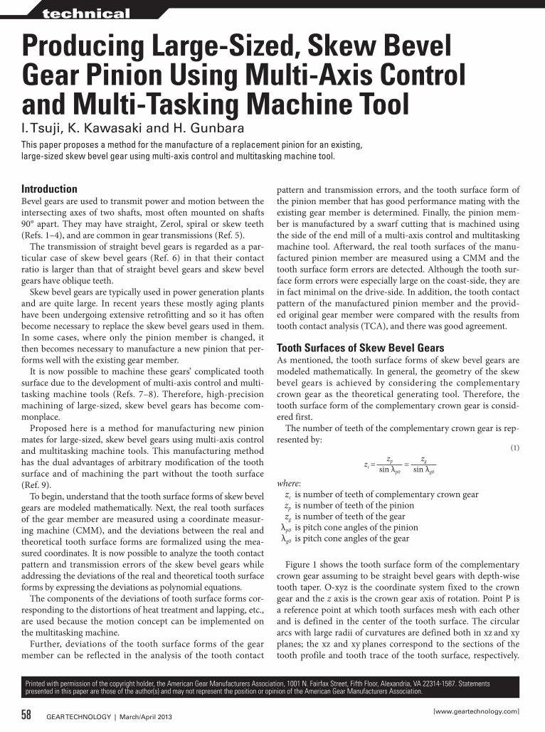
Figure 1 shows the tooth surface form of the complementary crown gear assuming to be straight bevel gears with depth-wise tooth taper. O-xyz is the coordinate system fixed to the crown gear and the z axis is the crown gear axis of rotation. Point P is a reference point at which tooth surfaces mesh with each other and is defined in the center of the tooth surface. The circular arcs with large radii of curvatures are defined both in xz and xy planes; the xz and xy planes correspond to the sections of the tooth profile and tooth trace of the tooth surface, respectively.
Producing Large-sized, skew Bevel Gear Pinion Using Multi-Axis Control and Multi-Tasking Machine Tooli. Tsuji, k. kawasaki and H. GunbaraThis paper proposes a method for the manufacture of a replacement pinion for an existing, large-sized skew bevel gear using multi-axis control and multitasking machine tool.
58 GEAR TECHNOLOGY | March/April 2013[www.geartechnology.com]
technical
This curved surface is defined as the tooth surface of the com-plementary crown gear. The following equations demonstrate the relations between ρc, Δc and Mn in xz, and between ρs, Δs and b in xy planes, respectively (Ref. 10).
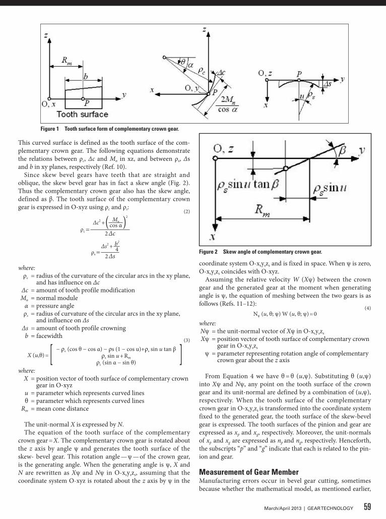
Since skew bevel gears have teeth that are straight and oblique, the skew bevel gear has in fact a skew angle (Fig. 2). Thus the complementary crown gear also has the skew angle, defined as β. The tooth surface of the complementary crown gear is expressed in O-xyz using ρc and ρs: (2)
ρc =Δc2 +( Mn )2
cos α2 Δc
ρs =Δs2 + b2
42 Δs
where: ρc = radius of the curvature of the circular arcs in the xy plane,
and has influence on Δc Δc = amount of tooth profile modification Mn = normal module α = pressure angle ρs = radius of curvature of the circular arcs in the xy plane,
and influence on Δs Δs = amount of tooth profile crowning b = facewidth
(3)
X (u,θ) = [ − ρc (cos θ − cos α) − ρs (1 − cos u)+ρs sin u tan β ρs sin u + Rm
ρc (sin α − sin θ) ]where: X = position vector of tooth surface of complementary crown
gear in O-xyz u = parameter which represents curved lines θ = parameter which represents curved lines Rm = mean cone distance
The unit-normal X is expressed by N.The equation of the tooth surface of the complementary
crown gear = X. The complementary crown gear is rotated about the z axis by angle ψ and generates the tooth surface of the skew- bevel gear. This rotation angle — ψ — of the crown gear, is the generating angle. When the generating angle is ψ, X and N are rewritten as Xψ and Nψ in O-xsyszs, assuming that the coordinate system O-xyz is rotated about the z axis by ψ in the
coordinate system O-xsyszs and is fixed in space. When ψ is zero, O-xsyszs coincides with O-xyz.
Assuming the relative velocity W (Xψ) between the crown gear and the generated gear at the moment when generating angle is ψ, the equation of meshing between the two gears is as follows (Refs. 11–12):
(4)Nψ (u, θ; ψ) W (u, θ; ψ) = 0
where: Nψ = the unit-normal vector of Xψ in O-xsyszs
Xψ = position vector of tooth surface of complementary crown gear in O-xsyszs
ψ = parameter representing rotation angle of complementary crown gear about the z axis
From Equation 4 we have θ = θ (u,ψ). Substituting θ (u,ψ) into Xψ and Nψ, any point on the tooth surface of the crown gear and its unit-normal are defined by a combination of (u,ψ), respectively. When the tooth surface of the complementary crown gear in O-xsyszs is transformed into the coordinate system fixed to the generated gear, the tooth surface of the skew-bevel gear is expressed. The tooth surfaces of the pinion and gear are expressed as xp and xg, respectively. Moreover, the unit-normals of xp and xg are expressed as np and ng, respectively. Henceforth, the subscripts “p” and “g” indicate that each is related to the pin-ion and gear.
Measurement of Gear MemberManufacturing errors occur in bevel gear cutting, sometimes because whether the mathematical model, as mentioned earlier,
Figure 1 Tooth surface form of complementary crown gear.
Figure 2 skew angle of complementary crown gear.
59March/April 2013 | GEAR TECHNOLOGY
fits the real tooth surface of the existing gear member or not, is not obvious. Therefore the tooth surfaces of the gear member are measured using a CMM and the deviations between the real and theoretical tooth surface forms are formalized.
Coordinate measurement of real tooth surface. The theoreti-cal tooth surfaces of the gear member are expressed as xg (ug,ψg), as mentioned. A grid of n lines and m columns is defined and a point — or reference point — is specified on the tooth surfaces of both the drive- and coast-sides; the reference point is usu-ally plotted in the center of the grid. The position vectors xg (x, y, z) — namely, u, θ and ψ — are determined for the solution of simultaneous equations by considering one point on the grid of the tooth surface; the unit-normal (nx, ny, nz) of the correspond-ing surface point is also determined since u, θ and ψ are deter-mined (Ref. 13).
For measurement, the gear member is set up arbitrarily on a CMM whose coordinate system is defined as Om-xmymzm. We can make origin Om and axis zm coincide with the origin and the axis of the gear member, respectively. The whole grid of sur-face points, together with the theoretical tooth surfaces, is rotat-ed about the zm axis so that ym is equal to zero at the reference point. Therefore, the position vector of the point and its unit-normal are transformed into the coordinate system Om-xmymzm and are represented by:
(5)
x(i) = (x(i), y(i), z(i))T
(i = 1, 2, …, 2nm)n(i) = (nx
(i), ny(i), nz
(i))T
where: x(i) is the position vector of the i-th point of tooth surface in
Om- xmymzm
n(i) is the unit-normal vector of x(i)
The real tooth surface of the gear member was measured using a CMM (Sigma M and M3000 developed by Gleason Works). When the real tooth surface is measured according to the provided grid, the i-th-measured tooth surface coordinates are obtained and numerically expressed as the position vector (Refs. 13–14):
(6)xm
(i) = (xm(i), ym
(i), zm(i))T (i = 1, 2, …, 2nm)
where: Xm
(i) is the position vector of the i-th-measured tooth surface coordinates in Om-xmymzm
When the deviation δ between the measured coordinates and nominal data of the theoretical tooth surfaces for each point on the grid is defined towards the direction of the normal of the theoretical tooth surface, i-th δ can be determined by:
(7)δ(i) = (xm
(i) - x(i)) n(i) (i = 1, 2, …, 2nm)where:
the deviation between measured coordinates and nominal data of tooth surface is δ(i) for each point on the grid towards the direction of the normal of tooth surface; δ is equal to zero at the reference point.
The fundamental components of the deviations of tooth sur-face forms corresponding with the distortions of heat treatment and lapping, etc., are used because the motion concept may be implemented on a multitasking machine.
Formalization of deviations of tooth surface form. Based on the method mentioned earlier, the deviation δ for each point on the grid is calculated when the points on the tooth surface are measured (Ref. 15). However, it is difficult to ideally fit δ to the theoretical tooth surface because δ varies at each point on the grid. We therefore define (X, Y) whose X and Y are toward the directions of the tooth profile and tooth trace, respectively, and form the following polynomial expression:
(8)δ = δ11 + δ12 + δ21 + δ22 + δ31 + δ32 + δ41
where: δ11 = parameter-defining deviation δ12 = parameter-defining deviation δ21 = parameter-defining deviation δ22 = parameter-defining deviation δ31 = parameter-defining deviation δ32 = parameter-defining deviation δ41 = parameter-defining deviation
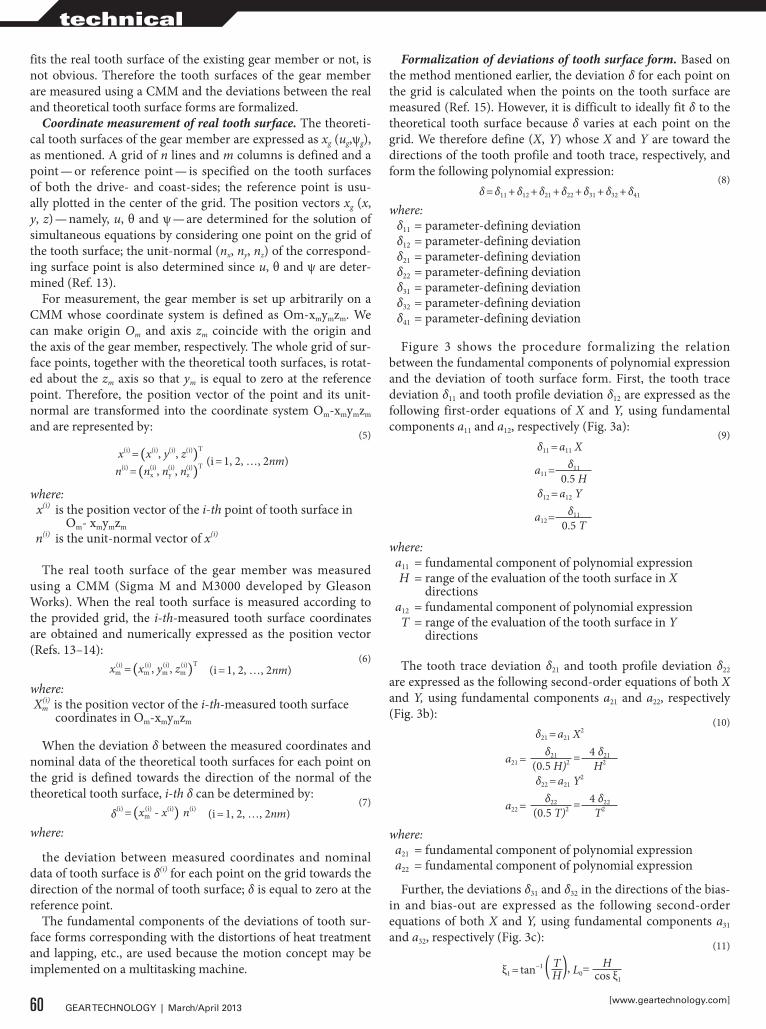
Figure 3 shows the procedure formalizing the relation between the fundamental components of polynomial expression and the deviation of tooth surface form. First, the tooth trace deviation δ11 and tooth profile deviation δ12 are expressed as the following first-order equations of X and Y, using fundamental components a11 and a12, respectively (Fig. 3a):
(9)δ11 = a11 X
a11 =δ11
0.5 Hδ12 = a12 Y
a12 =δ11
0.5 T
where: a11 = fundamental component of polynomial expression H = range of the evaluation of the tooth surface in X
directions a12 = fundamental component of polynomial expression T = range of the evaluation of the tooth surface in Y
directions
The tooth trace deviation δ21 and tooth profile deviation δ22 are expressed as the following second-order equations of both X and Y, using fundamental components a21 and a22, respectively (Fig. 3b):
(10)δ21 = a21 X2
a21 =δ21 = 4 δ21
(0.5 H)2 H2
δ22 = a21 Y2
a22 =δ22 = 4 δ22
(0.5 T)2 T2
where: a21 = fundamental component of polynomial expression a22 = fundamental component of polynomial expression
Further, the deviations δ31 and δ32 in the directions of the bias-in and bias-out are expressed as the following second-order equations of both X and Y, using fundamental components a31 and a32, respectively (Fig. 3c):
(11)
ξ1 = tan−1 ( T ), L0=H
H cos ξ1
60 GEAR TECHNOLOGY | March/April 2013[www.geartechnology.com]
technical
δ31 = a31 (X cos ξ1 − Y sin ξ1)2
a31 =δ31 = 4 δ31
(0.5 L0)2 H02
δ32 = a32 (X cos ξ1 − Y sin ξ1)2
a32 =δ32 = 4 δ31
(0.5 L0)2 L02
where: a31 = fundamental component of polynomial expression a32 = fundamental component of polynomial expression
The tooth trace deviation δ41 is expressed as the following third-order equations of X and Y, using fundamental compo-nents b1, b2 and b3, respectively (Fig. 3d):
(12)δ41 = b3X3 + b2X2 + b1X
Thus b1, b2 and b3 are determined from the following condi-tions: δ is equal to zero when X = -0.5H and X = 0.5H. In addi-tion, δ is equal to δ41 when X = 0.25H. Reflecting the polynomial expression δ to the theoretical tooth surface, the position vector is represented by:
(13)xa = x + δ n
Thus xa describes the theoretical tooth surface with consid-eration of the tooth surface form deviations. The tooth contact patterns and transmission errors with the tooth surface form deviations are analyzed using xa. The position vector of the i-th point of the theoretical tooth surface is expressed as xa
(i).
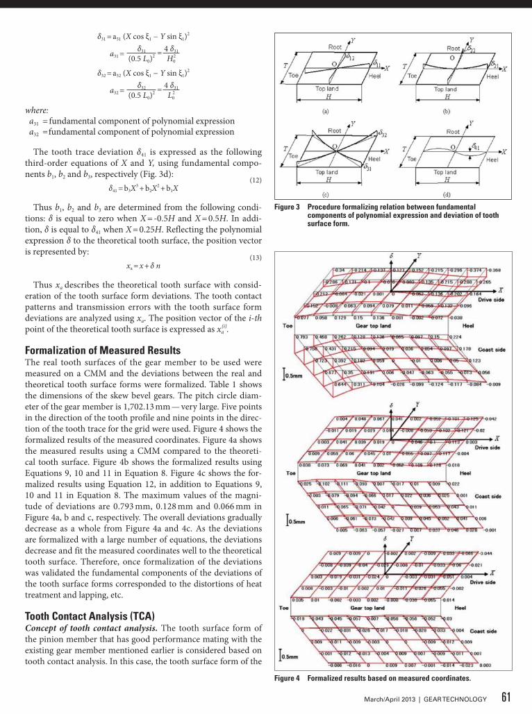
Formalization of Measured ResultsThe real tooth surfaces of the gear member to be used were measured on a CMM and the deviations between the real and theoretical tooth surface forms were formalized. Table 1 shows the dimensions of the skew bevel gears. The pitch circle diam-eter of the gear member is 1,702.13 mm — very large. Five points in the direction of the tooth profile and nine points in the direc-tion of the tooth trace for the grid were used. Figure 4 shows the formalized results of the measured coordinates. Figure 4a shows the measured results using a CMM compared to the theoreti-cal tooth surface. Figure 4b shows the formalized results using Equations 9, 10 and 11 in Equation 8. Figure 4c shows the for-malized results using Equation 12, in addition to Equations 9, 10 and 11 in Equation 8. The maximum values of the magni-tude of deviations are 0.793 mm, 0.128 mm and 0.066 mm in Figure 4a, b and c, respectively. The overall deviations gradually decrease as a whole from Figure 4a and 4c. As the deviations are formalized with a large number of equations, the deviations decrease and fit the measured coordinates well to the theoretical tooth surface. Therefore, once formalization of the deviations was validated the fundamental components of the deviations of the tooth surface forms corresponded to the distortions of heat treatment and lapping, etc.
Tooth Contact Analysis (TCA)Concept of tooth contact analysis. The tooth surface form of the pinion member that has good performance mating with the existing gear member mentioned earlier is considered based on tooth contact analysis. In this case, the tooth surface form of the
Figure 3 Procedure formalizing relation between fundamental components of polynomial expression and deviation of tooth surface form.
Figure 4 Formalized results based on measured coordinates.
61March/April 2013 | GEAR TECHNOLOGY
pinion member is modeled using Equation 1and the appropriate amount of profile modification and crowning is calculated.
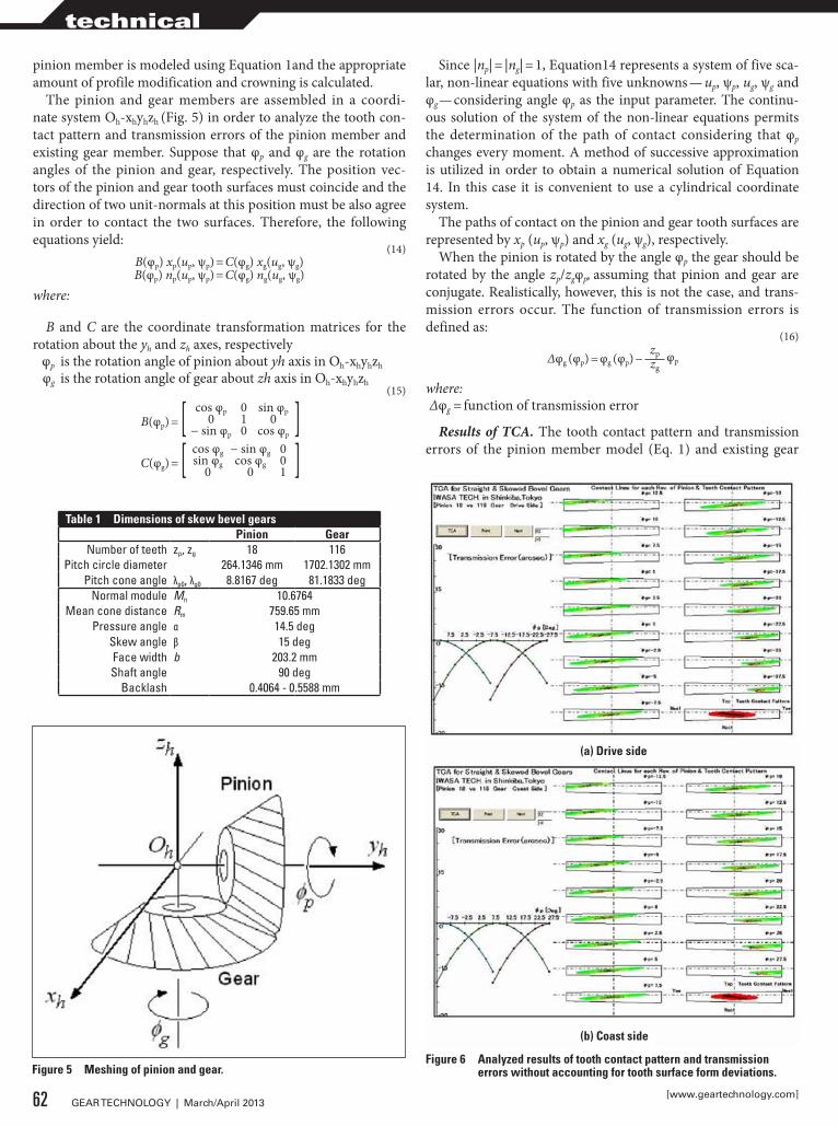
The pinion and gear members are assembled in a coordi-nate system Oh-xhyhzh (Fig. 5) in order to analyze the tooth con-tact pattern and transmission errors of the pinion member and existing gear member. Suppose that φp and φg are the rotation angles of the pinion and gear, respectively. The position vec-tors of the pinion and gear tooth surfaces must coincide and the direction of two unit-normals at this position must be also agree in order to contact the two surfaces. Therefore, the following equations yield:
(14)B(φp) xp(up, ψp) = C(φg) xg(ug, ψg)B(φp) np(up, ψp) = C(φg) ng(ug, ψg)
where:
B and C are the coordinate transformation matrices for the rotation about the yh and zh axes, respectively φp is the rotation angle of pinion about yh axis in Oh-xhyhzh
φg is the rotation angle of gear about zh axis in Oh-xhyhzh(15)
B(φp) = [ cos φp 0 sin φp ]0 1 0− sin φp 0 cos φp
C(φg) = [ cos φg − sin φg 0 ]sin φg cos φg 00 0 1
Since |np| = |ng| = 1, Equation14 represents a system of five sca-lar, non-linear equations with five unknowns — up, ψp, ug, ψg and φg — considering angle φp as the input parameter. The continu-ous solution of the system of the non-linear equations permits the determination of the path of contact considering that φp
changes every moment. A method of successive approximation is utilized in order to obtain a numerical solution of Equation 14. In this case it is convenient to use a cylindrical coordinate system.
The paths of contact on the pinion and gear tooth surfaces are represented by xp (up, ψp) and xg (ug, ψg), respectively.
When the pinion is rotated by the angle φp the gear should be rotated by the angle zp/zgφp, assuming that pinion and gear are conjugate. Realistically, however, this is not the case, and trans-mission errors occur. The function of transmission errors is defined as:
(16)
Δφg (φp) = φg (φp) −zp φpzg
where: Δφg = function of transmission error
Results of TCA. The tooth contact pattern and transmission errors of the pinion member model (Eq. 1) and existing gear
Table 1 dimensions of skew bevel gearsPinion Gear
Number of teeth zp, zg 18 116Pitch circle diameter 264.1346 mm 1702.1302 mm
Pitch cone angle λp0, λg0 8.8167 deg 81.1833 degNormal module Mn 10.6764
Mean cone distance Rm 759.65 mmPressure angle α 14.5 deg
Skew angle β 15 degFace width b 203.2 mmShaft angle 90 deg
Backlash 0.4064 - 0.5588 mm
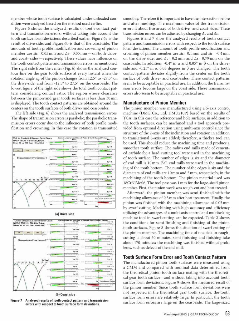
Figure 5 Meshing of pinion and gear.Figure 6 Analyzed results of tooth contact pattern and transmission
errors without accounting for tooth surface form deviations.
(a) drive side
(b) Coast side
62 GEAR TECHNOLOGY | March/April 2013[www.geartechnology.com]
technical
member whose tooth surface is calculated under unloaded con-dition were analyzed based on the method used earlier.
Figure 6 shows the analyzed results of tooth contact pat-tern and transmission errors, without taking into account the tooth surface form deviations described earlier. Figure 6a is the result of drive-side, and Figure 6b is that of the coast-side. The amounts of tooth profile modification and crowning of pinion member are Δc = 0.05 mm and Δs = 0.05 mm — on both drive- and coast- sides — respectively. These values have influence on the tooth contact pattern and transmission errors, as mentioned. The right side from the center (Fig. 6) shows the analyzed con-tour line on the gear tooth surface at every instant when the rotation angle φp of the pinion changes from 12.5° to -27.5° on the drive-side, and from -12.5° to 27.5° on the coast-side. The lowest figure of the right side shows the total tooth contact pat-tern considering contact ratio. The region whose clearance between the pinion and gear tooth surfaces is less than 30 mm is displayed. The tooth contact patterns are obtained around the centers on the tooth surfaces of both drive- and coast-sides.
The left side (Fig. 6) shows the analyzed transmission errors. The shape of transmission errors is parabolic; the parabolic trans-mission errors occur due to the influence of both profile modi-fication and crowning. In this case the rotation is transmitted
smoothly. Therefore it is important to have the intersection before and after meshing. The maximum value of the transmission errors is about five arcsec of both drive- and coast-sides. These transmission errors can be adjusted by changing Δc and Δs.
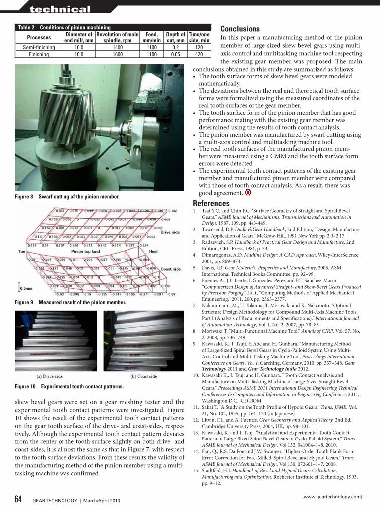
Figures 6 and 7 show the analyzed results of tooth contact pattern and transmission errors with respect to the tooth surface form deviations. The amount of tooth profile modification and crowning of pinion member are Δc = 0.1 mm and Δs = -0.4 mm on the drive-side, and Δc = 0.2 mm and Δs = 0.79 mm on the coast-side. In addition, -0.4° in α and 0.05° in β on the drive-side and -0.25° in α, 0.03 degrees in β are changed. The tooth contact pattern deviates slightly from the center on the tooth surface of both drive- and coast-sides. These contact patterns seem to be acceptable in practical use. In addition, the transmis-sion errors become large on the coast side. These transmission errors also seem to be acceptable in practical use.
Manufacture of Pinion MemberThe pinion member was manufactured using a 5-axis control machine (DMG Co., Ltd. DMU210P) based on the results of TCA. In this case the reference and hole surfaces, in addition to the tooth surfaces, can be machined and a tool approach pro-vided from optimal direction using multi-axis control since the structure of the 2-axis of the inclination and rotation in addition to translational 3-axis are added; therefore, a thicker tool can be used. This should reduce the machining time and produce a smoother tooth surface. The radius end mills made of cement-ed carbide for a hard cutting tool were used in the machining of tooth surface. The number of edges is six and the diameter of end mill is 10 mm. Ball end mills were used in the machin-ing of the tooth bottom. The number of the edges is six and the diameters of end mills are 10 mm and 5 mm, respectively, in the machining of the tooth bottom. The pinion material used was 18CrNiMo06. The tool pass was 1 mm for the large-sized pinion member. First, the pinion work was rough-cut and heat treated.
Afterward, the pinion member was semi-finished with the machining allowance of 0.3 mm after heat treatment. Finally, the pinion was finished with the machining allowance of 0.05 mm by swarf cutting. Machining with high accuracy and efficiency utilizing the advantages of a multi-axis control and multitasking machine tool in swarf cutting can be expected. Table 2 shows the conditions for semi-finishing and finishing of the pinion tooth surfaces. Figure 8 shows the situation of swarf cutting of the pinion member. The machining time of one side in rough-cutting is about 50 minutes; semi-finishing and finishing take about 170 minutes; the machining was finished without prob-lems, such as defects of the end-mill.
Tooth surface Form Error and Tooth Contact PatternThe manufactured pinion tooth surfaces were measured using a CMM and compared with nominal data determined from the theoretical pinion tooth surface mating with the theoreti-cal gear tooth surface—and without taking into account tooth surface form deviations. Figure 9 shows the measured result of the pinion member. Since tooth surface form deviations were not respected in the theoretical gear tooth surface, the tooth surface form errors are relatively large. In particular, the tooth surface form errors are large on the coast-side. The large-sized Figure 7 Analyzed results of tooth contact pattern and transmission
errors with respect to tooth surface form deviations.
(a) drive side
(b) Coast side
63March/April 2013 | GEAR TECHNOLOGY
skew bevel gears were set on a gear meshing tester and the experimental tooth contact patterns were investigated. Figure 10 shows the result of the experimental tooth contact patterns on the gear tooth surface of the drive- and coast-sides, respec-tively. Although the experimental tooth contact pattern deviates from the center of the tooth surface slightly on both drive- and coast-sides, it is almost the same as that in Figure 7, with respect to the tooth surface deviations. From these results the validity of the manufacturing method of the pinion member using a multi-tasking machine was confirmed.
ConclusionsIn this paper a manufacturing method of the pinion member of large-sized skew bevel gears using multi-axis control and multitasking machine tool respecting the existing gear member was proposed. The main
conclusions obtained in this study are summarized as follows:• The tooth surface forms of skew bevel gears were modeled
mathematically.• The deviations between the real and theoretical tooth surface
forms were formalized using the measured coordinates of the real tooth surfaces of the gear member.
• The tooth surface form of the pinion member that has good performance mating with the existing gear member was determined using the results of tooth contact analysis.
• The pinion member was manufactured by swarf cutting using a multi-axis control and multitasking machine tool.
• The real tooth surfaces of the manufactured pinion mem-ber were measured using a CMM and the tooth surface form errors were detected.
• The experimental tooth contact patterns of the existing gear member and manufactured pinion member were compared with those of tooth contact analysis. As a result, there was good agreement.
References1. Tsai Y.C. and Chin P.C. “Surface Geometry of Straight and Spiral Bevel
Gears,” ASME Journal of Mechanisms, Transmissions and Automation in Design, 1987, 109, pp. 443-449.
2. Townsend, D.P. Dudley’s Gear Handbook, 2nd Edition, “Design, Manufacture and Application of Gears,” McGraw-Hill, 1991 New York pp. 2.9–2.17.
3. Radzevich, S.P. Handbook of Practical Gear Design and Manufacture, 2nd Edition, CRC Press, 1984, p. 53.
4. Dimarogonas, A.D. Machine Design: A CAD Approach, Wiley-InterScience, 2001, pp. 869–874.
5. Davis, J.R. Gear Materials, Properties and Manufacture, 2005, ASM International Technical Books Committee, pp. 92–99.
6. Fuentes A., J.L. Iserte, I. Gonzales-Perez and F.T. Sanchez-Marin. “Computerized Design of Advanced Straight- and Skew-Bevel Gears Produced by Precision Forging,” 2011, “Computing Methods of Applied Mechanical Engineering,” 2011, 200, pp. 2363–2377.
7. Nakaminami, M., T. Tokuma, T. Moriwaki and K. Nakamoto. “Optimal Structure Design Methodology for Compound Multi-Axis Machine Tools, Part I (Analysis of Requirements and Specifications),” International Journal of Automation Technology, Vol. I, No. 2, 2007, pp. 78–86.
8. Moriwaki T. “Multi-Functional Machine Tool,” Annals of CIRP, Vol. 57, No. 2, 2008, pp. 736–749.
9. Kawasaki, K., I. Tsuji, Y. Abe and H. Gunbara. “Manufacturing Method of Large-Sized Spiral Bevel Gears in Cyclo-Palloid System Using Multi-Axis Control and Multi-Tasking Machine Tool, Proceedings International Conference on Gears, Vol. I, Garching, Germany, 2010, pp. 337–348, Gear Technology 2011 and Gear Technology India 2012.
10. Kawasaki K., I. Tsuji and H. Gunbara. “Tooth Contact Analysis and Manufacture on Multi-Tasking Machine of Large-Sized Straight Bevel Gears,” Proceedings ASME 2011 International Design Engineering Technical Conferences & Computers and Information in Engineering Conference, 2011, Washington D.C., CD-ROM.
11. Sakai T. “A Study on the Tooth Profile of Hypoid Gears,” Trans. JSME, Vol. 21, No. 102, 1955, pp. 164–170 (in Japanese).
12. Litvin, F.L. and A. Fuentes. Gear Geometry and Applied Theory, 2nd Ed., Cambridge University Press, 2004, UK, pp. 98–101.
13. Kawasaki, K. and I. Tsuji. “Analytical and Experimental Tooth Contact Pattern of Large-Sized Spiral Bevel Gears in Cyclo-Palloid System,” Trans. ASME Journal of Mechanical Design, Vol.132, 041004–1–8, 2010.
14. Fan, Q., R.S. Da Foe and J.W. Swanger. “Higher-Order Tooth Flank Form Error Correction for Face-Milled, Spiral Bevel and Hypoid Gears,” Trans. ASME Journal of Mechanical Design, Vol.130, 072601–1–7, 2008.
15. Stadtfeld, H.J. Handbook of Bevel and Hypoid Gears: Calculation, Manufacturing and Optimization, Rochester Institute of Technology, 1993, pp. 9–12.
Table 2 Conditions of pinion machining
Processes diameter of end mill, mm
Revolution of main spindle, rpm
Feed, mm/min
depth of cut, mm
Time/one side, min
Semi-finishing 10.0 1400 1100 0.2 120Finishing 10.0 1600 1100 0.05 420
Figure 10 Experimental tooth contact patterns.
Figure 8 swarf cutting of the pinion member.
Figure 9 Measured result of the pinion member.
64 GEAR TECHNOLOGY | March/April 2013[www.geartechnology.com]
technical