The Fluid Flow Field Characteristics Analysis of ...
7
The Fluid Flow Field Characteristics Analysis of Automobile ABS Storage Tank Based on CFD ZHANG WenTao 1, a , Yao Liang 2,b 1 , 2 College of Mechanical and Electric Engineering Changchun University of Science and Technology Changchun, Jilin Province, 130022, P. R. China Email: [email protected] * 1 Corresponding author:Zhang Wentao Key words:Storage tank;Multiphase flow;UDF;Transient analysis;CFD Abstract:The automobile ABS is an important device for safe driving. The properties of the brake fluid are closely related to the automobile braking efficiency. The gas-liquid two phase flow often occurs in the brake fluid for various reasons, which affects the transmission characteristics of brake fluid pressure wave, it results in a decline in the performance of the automobile braking system. This paper mainly researches on the formation of two phase flow in the storage tank in the process of braking. The fluid flow field characteristics are analyzed based on multiphase flow of CFD. The flow state of the brake fluid is simulated based on the standard turbulence model. The standard of the air mixed into the brake fluid and the movement law of gas-liquid two phase flow are analyzed. The inflence of the shape and internal partitions of a storage tank is discussed. Introduction The hydraulic ABS operates according to the pascal principle[1]. The hydraulic ABS has the advantages of high transmission efficiency and quick response etc. Brake liquid is an important actuating medium in transfering the force from the brake pedal to the friction plate. The properties of brake fluid are the key factors for the ABS performance in braking process[2,3,4]. Due to the deterioration of brake fluid properities, especially the two phase flow of gas-liquid occurs in the ABS hydraulic system, the ABS performance is affected seriously. If the actuating medium in the master cylinder is the mixture of brake liquid, air and the steam of brake fluid, brake pressure decreases and can not be transferred to wheel cylinder quickly. The dynamic response of brake system is slow, even the brake system does not operate, It brings serious impacts on safe driving. When the bubbles of cavitation flow into high pressure areas in brake fluid, the bubble bursts quickly and condenses into liquid[5], its volume reduces suddenly, as a result the vacuum space forms. Therefore the brake fluid around will quickly flow to be the supplement, and the local hydraulic impact happens at the moment. The pressure and temperature rise dramaticlly, and the strong noise and vibration are produced. Due to the long-term impact of high temperature and high pressure, cavitation erossion, which shortens the life of the brake device, will take place. The storage tank is an important part of the ABS , it is composed of upper and lower housing, it stores and provides enougn brake liquid for ABS. At the time it also recycles the brake liquid which leaves form accumulator when the braking system operates. The brake fluid in the storage tank suffers severe shock and vibration when a vehicle runs, especially, brakes frequently. The mixture of brake liquid, air and the stem forms, and the temperature of brake liquid rises. The properties of brake fluid are influenced greatly[6], as a result, the 3rd International Conference on Mechatronics and Information Technology (ICMIT 2016) © 2016. The authors - Published by Atlantis Press 618
Transcript of The Fluid Flow Field Characteristics Analysis of ...

The Fluid Flow Field Characteristics Analysis of Automobile ABS Storage Tank Based on CFD
ZHANG WenTao1, a, Yao Liang2,b 1,2College of Mechanical and Electric Engineering
Changchun University of Science and Technology
Changchun, Jilin Province, 130022, P. R. China
Email: [email protected]
*1Corresponding author:Zhang Wentao
Key words:Storage tank;Multiphase flow;UDF;Transient analysis;CFD Abstract:The automobile ABS is an important device for safe driving. The properties of the brake fluid are closely related to the automobile braking efficiency. The gas-liquid two phase flow often occurs in the brake fluid for various reasons, which affects the transmission characteristics of brake fluid pressure wave, it results in a decline in the performance of the automobile braking system. This paper mainly researches on the formation of two phase flow in the storage tank in the process of braking. The fluid flow field characteristics are analyzed based on multiphase flow of CFD. The flow state of the brake fluid is simulated based on the standard turbulence model. The standard of the air mixed into the brake fluid and the movement law of gas-liquid two phase flow are analyzed. The inflence of the shape and internal partitions of a storage tank is discussed.
Introduction
The hydraulic ABS operates according to the pascal principle[1]. The hydraulic ABS has the advantages of high transmission efficiency and quick response etc. Brake liquid is an important actuating medium in transfering the force from the brake pedal to the friction plate. The properties of brake fluid are the key factors for the ABS performance in braking process[2,3,4]. Due to the deterioration of brake fluid properities, especially the two phase flow of gas-liquid occurs in the ABS hydraulic system, the ABS performance is affected seriously. If the actuating medium in the master cylinder is the mixture of brake liquid, air and the steam of brake fluid, brake pressure decreases and can not be transferred to wheel cylinder quickly. The dynamic response of brake system is slow, even the brake system does not operate, It brings serious impacts on safe driving. When the bubbles of cavitation flow into high pressure areas in brake fluid, the bubble bursts quickly and condenses into liquid[5], its volume reduces suddenly, as a result the vacuum space forms. Therefore the brake fluid around will quickly flow to be the supplement, and the local hydraulic impact happens at the moment. The pressure and temperature rise dramaticlly, and the strong noise and vibration are produced. Due to the long-term impact of high temperature and high pressure, cavitation erossion, which shortens the life of the brake device, will take place. The storage tank is an important part of the ABS , it is composed of upper and lower housing, it stores and
provides enougn brake liquid for ABS. At the time it also recycles the brake liquid which leaves form accumulator
when the braking system operates. The brake fluid in the storage tank suffers severe shock and vibration when a
vehicle runs, especially, brakes frequently. The mixture of brake liquid, air and the stem forms, and the
temperature of brake liquid rises. The properties of brake fluid are influenced greatly[6], as a result, the
3rd International Conference on Mechatronics and Information Technology (ICMIT 2016)
© 2016. The authors - Published by Atlantis Press 618
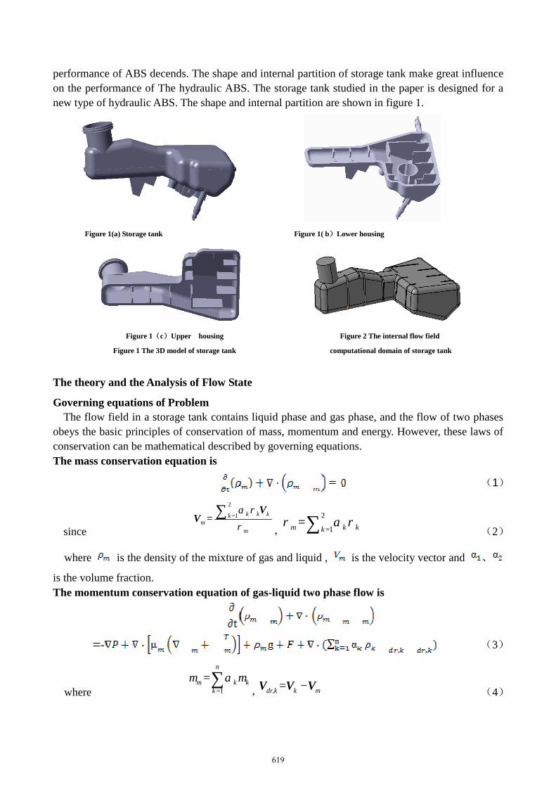
performance of ABS decends. The shape and internal partition of storage tank make great influence on the performance of The hydraulic ABS. The storage tank studied in the paper is designed for a new type of hydraulic ABS. The shape and internal partition are shown in figure 1.
Figure 1(a) Storage tank Figure 1( b)Lower housing
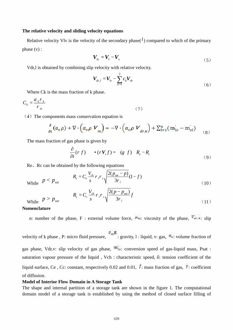
Figure 1(c)Upper housing Figure 2 The internal flow field
Figure 1 The 3D model of storage tank computational domain of storage tank
The theory and the Analysis of Flow State
Governing equations of Problem The flow field in a storage tank contains liquid phase and gas phase, and the flow of two phases obeys the basic principles of conservation of mass, momentum and energy. However, these laws of conservation can be mathematical described by governing equations. The mass conservation equation is
(1)
since
2
1= k k kkm
m
α ρ
ρ=∑ V
V,
2
1=m k kk
ρ α ρ=∑ (2)
where is the density of the mixture of gas and liquid , is the velocity vector and 、
is the volume fraction. The momentum conservation equation of gas-liquid two phase flow is
- (3)
where 1=
n
m k kk
µ α µ=
∑,
=dr,k k m−V V V (4)
619
The relative velocity and sliding velocity equations
Relative velocity Vlv is the velocity of the secondary phase( l ) compared to which of the primary
phase (v) :
lv l v= −V V V (5) Vdr,l is obtained by combining slip velocity with relative velocity.
2
,1
dr l lv k vkk
c=
= −∑V V V (6)
Where Ck is the mass fraction of k phase.
k kk
m
C α ρρ
= (7)
(4)The components mass conservation equation is
(8)
The mass fraction of gas phase is given by
( ) ( ) ( )v e cf f f R R
tρ ρ γ
∂+ ∇ • = ∇ ∇ + −
∂V
(9)
Re、Rc can be obtained by the following equations
While satp p<
2( ) (1 )3
ch sate e l v
l
V p pR C fρ ρσ ρ
−= −
(10)
While satp p>
2( )3
ch satc c l v
l
V p pR C fρ ρσ ρ
−=
(11) Nomenclature
n: number of the phase, F : external volume force, : viscosity of the phase, : slip
velocity of k phase , P: micro fluid pressure, : gravity, l : liquid, v: gas, : volume fraction of
gas phase, Vdr,v: slip velocity of gas phase, : conversion speed of gas-liquid mass, Psat :
saturation vapour pressure of the liquid , Vch : characteristic speed, б: tension coefficient of the
liquid surface, Ce , Cc: constant, respectively 0.02 and 0.01, : mass fraction of gas, : coefficient
of diffusion. Model of Interior Flow Domain in A Storage Tank The shape and internal partition of a storage tank are shown in the figure 1. The computational domain model of a storage tank is established by using the method of closed surface filling of
620

CATIA , as shown in the figure 2. Spatial Discretization The internal flow domain is discreted based on ANSYS ICEM. The unstructured grid(Tetra/Mixed) is setted to form the tetrahedral grids. The Scale factor is defined 1 among the global parameters of grid, and the maximal element is 2.5, and the total of generated grid is 526906. The grid quality is greater than 0.3, which meets the computing requirements. The model of discrete internal flow domain is shown in figure 3.
Figure 3:The model of discrete internal flow Figure 4:The initial volume of components
domain of storage tank of computational domain
Initial and Boundary Conditions The flow field characteristics of brake liquid in a storage tank are studied in this paper, when a vehicle goes at the speed of 36km/h, 60km/h and 100km/h , and decelerates to stop at acceleration 10m/s2. The file, which includes the information of the model of discrete internal flow domain, is imported into FLUENT. The Pressure-Based solver is set, and the time’s type is set to Transient. In the analysis, gravity should also be considered at the same time. The acceleration of gravity is -9.8m/s2 in the Y direction. The computational domain is divided into liquid region and gas region by choosing the VOF model of FLUENT, the mian phase is liquid and the secondary phase is air. The motion of the computational domain is controlled by using a custom function UDF(User Define Function), The process makes use of C++ to write a function of braking process at different speed, and the movement boundary conditions were loaded dynamically by the FLUENT solver successfully. The brake fluid is BOSCH DOT4, the kinematic viscosity μ=1800mm2/s , the density ρ=1.06g/cm3. The initial volumes of components of computational domain are shown in figure 4, the red area is the brake fluid in the figure, the primary phase volume fraction (brake fluid) is 100%, the blue area is air, the secondary phase ( air) volume fraction is 100% , the interface of brake fluid and air is green. The whole model is set to fixed wall, the calculation conditions are set to unsteady flow model, the pressure-velocity correlation algorithm of PISO is launched to initialize the model, the Patch operation is performed on the model, and monitoring the speed of X direction is done in the process of calculating . The grid properties and FLUENT solver settings are listed in table 1.
Table1. The grid properties and FLUENT solver settings The initial
velocity[km/h] Grid type Grid number
Time step [s]
The step to solve
Computation time[min]
36 Tetra/Mixed 526906 0.0005 2200 2574 60 Tetra/Mixed 526906 0.0005 3540 4142 100 Tetra/Mixed 526906 0.0005 5740 6716
621

Results and Discussions
Figure 5 shows the volume component diagram of internal flow field in a storage tank at different time,while a vehicle decelebrates to stop at 36km/h with acceleration 10m/s2 . It indicates that the internal partition, perpendicular to the movement direction of the storage tank, has an excellent inhibiting effect on the violent movement of fluid, it is shown from figure 5(a) to 5(e) . The yellow area is the brake liquid mixed with lots of air, whose volume fraction is about 70%. The proportion of air-mixed brake liquid is low, and it mainly gathers in the upper end of a storage tank in the process of braking at 36 km/h. The fluid moves more violently during the braking process at speed of 60km/h , and The volume of air-mixed brake liquid increases. As shown from figure 6(a) to 6(f) , it gathers in the most tail space of a storage tank. In the process of braking at speed of 100km/h , the brake liquid moves violently , and the volume of air-mixed brake liquid increases significantly, As shown in figure from 7(a) to 7(g) , lots of air-mixed brake fluid almost fulfills the tail space of a storage tank and spreads to the front space of the tank. However, as shown in figure 7(g), it still concentrated in the tail space of the tank. Under the condition of this three kinds of speed , all the brake fluid didn’t touch the mouth of the tank in the braking events.
In these three cases, the reasonable shape and internal partition of a storage tank can effectly prevent brake liquid from spilling out in braking, and keep air from mixing into brake liquid. The
Figure 5(a) t=0.2s Figure 5(b) t=0.4s Figure5(c) t=0.6s
Figure 5(d) t=0.8s Figure 5(e) t=1.0s Figure 5 v=36km/h diagram of volume component in a storage tank
Figure 6(a) t=0.3s Figure 6(b) t=0.6s Figure 6(c) t=0.9s
622

Figure 6(d) t=1.2s Figure 6(e) t=1.5s Figure 6(f) t=1.0 s
Figure 6 v=60km/h diagram of volume component in a storage tank
Figure 7(a) t=0.4s Figure 7(b) t=0.8s Figure 7(c) t=1.2s
Figure 7(d) t=1.6s Figure 7(e) t=2.0s Figure 7(f) t=2.4s
Figure 7(g) t=2.8s
Figure 7 v=100km/h diagram of volume component in a storage tank storage tank with internal partitions can efficiently prevent the brake fluid from moving violently in high speed braking, and it can be concluded that temperature rising is controlled. As a result, the volume of both air-liquid mixture and volatile matter reduces significantly. Lots of air-mixed brake fluid , air and volatile matter of brake fluid are far away from the entrance of ABS pipeline. It preserves the properties of brake liquid that enters the ABS pipeline system. The performance of braking system of ABS is guaranteed greatly. All above factors ensure ABS to response quickly and work stably and reliably in frequent braking.
The flow field characteristics of brake liquid in a storage tank in the forward direction of braking process are simulated in the paper. In fact, the actual braking process is more complex. The
623

reasonable shape and internal partition of a storage tank are very important factors for preserving the quality and properties of brake liquid, and it is valuable to achieve the safe, reliable, rapid response and high efficient performance of ABS .
Conclusions
This paper conducts a simulation analysis on the internal features of complex flow field of an ABS storage tank by using FLUENT software. Diagrams of volume component in a storage tank and the flow rules of brake fluid at different moment are achieved under the condition of three kinds of speed. The reasonable shape and internal partition of a storage tank can effectively prevent the brake fluid from moving freely and violently , being mixed with air in high-speed braking. It can concluded that the quality and properties of brake liquid are preserved for a long time by optimal design of a storage tank. As a result, the braking performance of ABS is guaranteed to be efficient, reliable, and rapid response, And it is of great significance in improving the life of ABS.
The CFD method provides an intuitionistic, reliable and efficient means for further studying the characteristics of complex flow field.
References
[1] Zhu Xi Cheng The design of automobile anti-lock braking system[M].Xi An:Northwestern Polytechnical University,2005. [2] Li Xiao Lu,Sun Hua.Automobile ABS gas; liquid two phase flow’s influence on the brake pressure [J].Automotive safety and Journal of energy saving,2012,3(3):218-224. [3]LEE Kwangjin. Numerical Prediction of Brake Fluid Temperature Rise during Braking and Heat Soaking [R]. SAE Paper, 1999-01-0483. [4]Hunter J E, Cartier S S, Temple D J, et al. Brake fluid vaporization as a contributing factor in motor vehiclecollisions [R]. SAE Paper, 980371. [5]Huang Fei,Bai Bo Feng,Guo Lie Jin.Gas-liquid two-phase bubbly flow in a horizontal pipe pressure wave mathematical model and its numberical simulation[J].Progress in natural science,2004,14(1):88-94. [6]Ding Wen Si.Vehicle brake tubing liquid pressure transfer characteristics analysis[J].Application base and Journal of engineering science,2011,19(3):466–473. [7]Ding Hong Xing,Wang Xian Bin.Response characteristics simulation automobile brake line pressure fluctuations[J].Journal of Wu Han university of technology:Engineering information and management,2010,32(4):573–575. [8]Jang Dan,Li Song Jing,Bao Gang.With bubbles and air hole hydraulic pipeline transient analysis of low pressure[J].Engineering mechanics,2007,24(11): 36-40.
624