THE FENTON BALANCED FLUE - Nu-Flame
34
THE FENTON BALANCED FLUE BALANCED FLUE CONVECTION HEATER SUITABLE FOR NATURAL GAS & PROPANE USE, INSTALLATION & SERVICING INSTRUCTIONS The glass panel and outer parts of this fire will become hot during use, cloths or combustible items must not be placed close to or on the fire. We recommend that a Fireguard conforming to BS8423 should be used for protection of Young Children the Elderly, Infirm and Pets. ALL INSTRUCTIONS MUST BE LEFT WITH THE USER FOR SAFE KEEPING MANUFACTURED by: Nu-Flame Limited Unit 4, Kimpton Trade & Business Centre Minden Road, Sutton, Surrey SM3 9PF Tel: 020 8254 6802 Fax: 020 8641 9992 Email: [email protected] Country of Destination – GB & IE Revision 12.9.19 GAR
Transcript of THE FENTON BALANCED FLUE - Nu-Flame

THE FENTON BALANCED FLUE
BALANCED FLUE CONVECTION HEATER SUITABLE FOR NATURAL GAS & PROPANE
USE, INSTALLATION & SERVICING INSTRUCTIONS
The glass panel and outer parts of this fire will become hot during use, cloths or combustible items must not be placed close to or on the fire. We recommend that a Fireguard conforming to BS8423
should be used for protection of Young Children the Elderly, Infirm and Pets.
ALL INSTRUCTIONS MUST BE LEFT WITH THE USER FOR SAFE KEEPING
MANUFACTURED by: Nu-Flame Limited
Unit 4, Kimpton Trade & Business Centre Minden Road, Sutton, Surrey SM3 9PF
Tel: 020 8254 6802 Fax: 020 8641 9992
Email: [email protected]
Country of Destination – GB & IE
Revision 12.9.19 GAR

2
CONTENTS Section No Subject Page
User Section
- Contents Page & Box Contents 2 - Fitting Kit Contents & Fitting Case Fixing Brackets 3 - Minimum Distances for Flue Terminal Positions 4 1 Important Notes 5 2 Lighting & Controlling the Fire 6 3 Cleaning the Fire 9 4 Servicing 9
Installation Section - Record Data 9 5 Installation Requirements 9 6 Appliance Data 10 7a,b Appliance & Max & Min Flue Length Dimensions 10, & 11 8 Flue Requirements 11 9 Ventilation 11 10 Gas Supply 11
14 Preparing Fire and Preparing the Flue 18 15 Fitting the Fire 19 16 Arrangement of the Fuel Effects Coal & Wood 21 17 Testing, Commissioning & Use 26 18 Briefing the Customer 26
19 Servicing 27 20 Fault Finding Guide, Symptoms & Possible Cause 27 21 Energy Class & Product Fiche EU Declaration of Conformity 30 22 EU Declaration of Conformity 32 23 Diagram of Infrared Control System 33
- Guarantee 34 BOX CONTENTS (The Fire comes in a number of boxes)
Box 1 - Large box - contains the Fire, the Matrix Tray, chosen Control System plus Fitting Kit (see overleaf for contents).
Box 2 - The Fuel Bed, (Coal or Wood and Matrix’s).
Box 3 - The Flue Assembly, Foam Flue Cutting Aid, Flue Wall Plate & Flue Terminal Guard. Box 4 - The Fenton Case with Fixing Brackets.
The Fenton Fixing Brackets will have to be fitted to the main Fire see the next page.
Sections 11 & 12 are for the various installation applications for Traditionally Built Houses
Section 13 covers the requirements for Timber Frame Houses
Ensure you refer to the Section relevant to your requirement
11 Traditional Property with Non Combustible Internal Walls Installations Standard & Rebated Surround, Back Panel, Slips & Shelf Details 12
12 Traditional Property with Combustible Internal Walls Installations Standard & Rebated Surround, Back Panel, Slips & Shelf Details 14
13 Timber Frame Installations 16

3
FENTON BALANCED FLUE FITTING KIT CONTENTS: 1 # Cable Fixing Kit (comprising 2 # cables and fittings, 4 # eye bolts, 4 # Rawl plugs). 3 # No10 x 40mm Stainless Steel Round Head Screws to fix Flue Terminal Guard. 3 # Stainless Steel Washers to fix Flue Terminal Guard. 7 # No10 Rawl plugs for fixing the Flue Terminal Guard & 4off for Wall Fixing rather than Cable Fixing the Fire. 3 # M5 x 25mm Stainless Steel Washers for fixing the Flue Terminal Guard. 8 # No10 x 40mm Stainless Steel Round Head Screws to fix Flue Wall Plate & 4off for Wall Fixing rather than Cable Fixing the Fire. 1 # 700mm length 6mm x 4mm self adhesive Silicone Sealing Strip for fixing to Flue Wall Plate. 4 # No10 Rawl plugs to fix Flue Wall Plate. 4 # No6 by 10mm self tapping screws for securing the Flue to the Wall Plate. 3 # No6 by 10mm self tapping screws for securing the Flue to the Spigot of the Fire. 1 # 2.5mm Steel Cutting Drill for drilling the flue. 1 # length of Aluminium Tape for sealing the flue. 1 # 10mm Back Nut & olive to connect 8mm copper pipe gas supply to the burner (via the isolation elbow). 1 # 2,050mm length of 5mm x 4mm self adhesive silicone sealing strip for around the frame and base of the fire. 1 # 1,820mm length of 5mm x 4mm self adhesive silicone sealing strip for around the Fenton Case. 1 # No2 Pozidriv screwdriver (for removal/fitting the Case and Glass Panel). 1 # Set of Instructions / Warranty. 1 # Spanner for Adjustment of the Case Feet.
PREPARING THE FENTON BALANCED FLUE FIRE - (Fenton Case & Main Fire)
IMPORTANT: The Fenton Case Upper and Lower Fixing Brackets Must be fitted to the Main Fire. Referring to the photographs proceed as follows:
b) Working at the Bottom Left of the Main Fire remove the 2 screws in the case and fit the left top Fenton Case Fixing Bracket as shown. Now repeat on the right side of the Main Fire and fit the Right Lower Fixing Bracket. For either Cable Fixing or Wall Fixing of the fire see Page 20.
a) Working at the Top Left of the Main Fire remove the 2 screws in the case and fit the left top Fenton Case Fixing Bracket as shown. Now repeat on the right side of the Main Fire and fit the Right Lower Fixing Bracket. For either Cable Fixing or Wall Fixing of the fire see Page 20.

4
* In addition, for temperature and structural reasons, the terminal should be no nearer than 300mm to an opening in
the building fabric formed for the purpose of accommodating a built in element such as a window frame.
** The reference to external corners does not apply to building protrusions not exceeding 450mm, such as disused
chimneys on external walls.
5
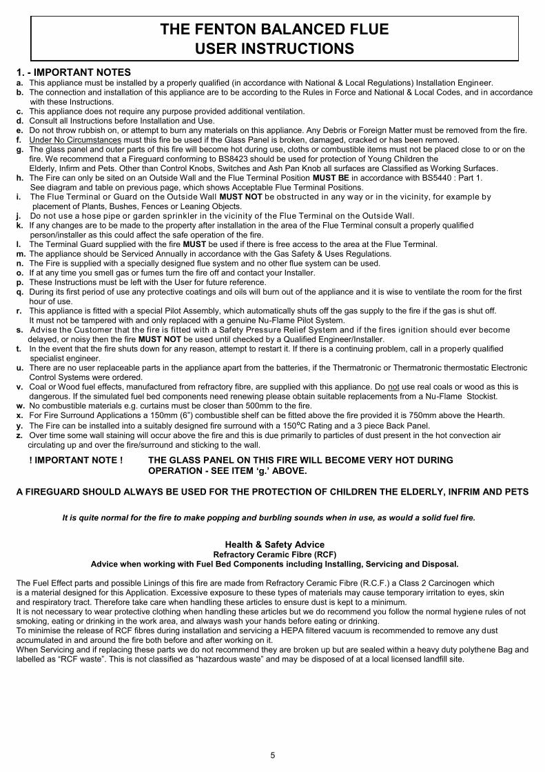
1. - IMPORTANT NOTES a. This appliance must be installed by a properly qualified (in accordance with National & Local Regulations) Installation Engineer. b. The connection and installation of this appliance are to be according to the Rules in Force and National & Local Codes, and in accordance with these Instructions. c. This appliance does not require any purpose provided additional ventilation. d. Consult all Instructions before Installation and Use. e. Do not throw rubbish on, or attempt to burn any materials on this appliance. Any Debris or Foreign Matter must be removed from the fire. f. Under No Circumstances must this fire be used if the Glass Panel is broken, damaged, cracked or has been removed. g. The glass panel and outer parts of this fire will become hot during use, cloths or combustible items must not be placed close to or on the
fire. We recommend that a Fireguard conforming to BS8423 should be used for protection of Young Children the Elderly, Infirm and Pets. Other than Control Knobs, Switches and Ash Pan Knob all surfaces are Classified as Working Surfaces. h. The Fire can only be sited on an Outside Wall and the Flue Terminal Position MUST BE in accordance with BS5440 : Part 1. See diagram and table on previous page, which shows Acceptable Flue Terminal Positions. i. The Flue Terminal or Guard on the Outside Wall MUST NOT be obstructed in any way or in the vicinity, for example by placement of Plants, Bushes, Fences or Leaning Objects. j. Do not use a hose pipe or garden sprinkler in the vicinity of the Flue Terminal on the Outside Wall. k. If any changes are to be made to the property after installation in the area of the Flue Terminal consult a properly qualified person/installer as this could affect the safe operation of the fire. l. The Terminal Guard supplied with the fire MUST be used if there is free access to the area at the Flue Terminal. m. The appliance should be Serviced Annually in accordance with the Gas Safety & Uses Regulations. n. The Fire is supplied with a specially designed flue system and no other flue system can be used. o. If at any time you smell gas or fumes turn the fire off and contact your Installer. p. These Instructions must be left with the User for future reference. q. During its first period of use any protective coatings and oils will burn out of the appliance and it is wise to ventilate the room for the first
hour of use. r. This appliance is fitted with a special Pilot Assembly, which automatically shuts off the gas supply to the fire if the gas is shut off. It must not be tampered with and only replaced with a genuine Nu-Flame Pilot System. s. Advise the Customer that the fire is fitted with a Safety Pressure Relief System and if the fires ignition should ever become delayed, or noisy then the fire MUST NOT be used until checked by a Qualified Engineer/Installer. t. In the event that the fire shuts down for any reason, attempt to restart it. If there is a continuing problem, call in a properly qualified specialist engineer. u. There are no user replaceable parts in the appliance apart from the batteries, if the Thermatronic or Thermatronic thermostatic Electronic
Control Systems were ordered. v. Coal or Wood fuel effects, manufactured from refractory fibre, are supplied with this appliance. Do not use real coals or wood as this is
dangerous. If the simulated fuel bed components need renewing please obtain suitable replacements from a Nu-Flame Stockist. w. No combustible materials e.g. curtains must be closer than 500mm to the fire. x. For Fire Surround Applications a 150mm (6”) combustible shelf can be fitted above the fire provided it is 750mm above the Hearth.
y. The Fire can be installed into a suitably designed fire surround with a 150ºC Rating and a 3 piece Back Panel. z. Over time some wall staining will occur above the fire and this is due primarily to particles of dust present in the hot convection air circulating up and over the fire/surround and sticking to the wall.
! IMPORTANT NOTE ! THE GLASS PANEL ON THIS FIRE WILL BECOME VERY HOT DURING OPERATION - SEE ITEM ‘g.’ ABOVE. A FIREGUARD SHOULD ALWAYS BE USED FOR THE PROTECTION OF CHILDREN THE ELDERLY, INFRIM AND PETS
It is quite normal for the fire to make popping and burbling sounds when in use, as would a solid fuel fire.
Health & Safety Advice
Refractory Ceramic Fibre (RCF) Advice when working with Fuel Bed Components including Installing, Servicing and Disposal.
The Fuel Effect parts and possible Linings of this fire are made from Refractory Ceramic Fibre (R.C.F.) a Class 2 Carcinogen which is a material designed for this Application. Excessive exposure to these types of materials may cause temporary irritation to eyes, skin and respiratory tract. Therefore take care when handling these articles to ensure dust is kept to a minimum. It is not necessary to wear protective clothing when handling these articles but we do recommend you follow the normal hygiene rules of not smoking, eating or drinking in the work area, and always wash your hands before eating or drinking. To minimise the release of RCF fibres during installation and servicing a HEPA filtered vacuum is recommended to remove any dust accumulated in and around the fire both before and after working on it. When Servicing and if replacing these parts we do not recommend they are broken up but are sealed within a heavy duty polythene Bag and labelled as “RCF waste”. This is not classified as “hazardous waste” and may be disposed of at a local licensed landfill site.
THE FENTON BALANCED FLUE
USER INSTRUCTIONS

6
2. - LIGHTING & CONTROLLING THE FIRE General The fire is available with 3 Control Options: a Manual Control (Fire is lit and adjusted manually), or Thermatronic Radio Frequency Electronic Control System (Fire is lit & operated with a Handset) or the Thermostatic Thermatronic Radio Frequency Electronic Control System (Fire is lit & operated with an Handset which also can control the room temperature plus other features). 2.1 - LIGHTING & CONTROLLING THE FIRE - MANUAL CONTROL Open the Door at the base of the Stove to get access to the Control Knob used to operate the Fire.
a. Switching On/Ignition. Depress the control knob & turn counter clockwise. Gas will flow to the Pilot Burner (Pilot Burner is visible looking down through the glass at the left side), the Piezo Igniter will give off first one, then, as you turn, a second high voltage spark & the Pilot Burner will Light. (More than one attempt may have to be made on first lighting.) Keep the Control Knob depressed for approximately 10 seconds to heat up the Thermocouple. Turn the Control Knob fully counter clockwise to release gas to the Main Burner.
b. Control of Gas Flow. Turning the Control Knob clockwise reduces the gas flow from Maximum to the Pre-Set Minimum Setting. Turning between Maximum & Minimum does not actuate the Piezo Igniter. The Control Valve can only be set on the Pilot by depressing the control knob & turning it to the pre-selected pilot position. c. Switching Off. Press the Control Knob in at the Pilot Position & turn Clockwise to Off.
Note - For manually controlled fires a black cover plate is supplied to cover some of the pipe work and associated fittings under the burner tray. This is freestanding and is for cosmetic purposes only; it need not be used If preferred. The controls can be operated with the cover in place (see photos on previous page).
2.2 - LIGHTING & CONTROLLING THE FIRE– THERMATRONIC HAND HELD RADIO FREQUENCY REMOTE CONTROL The Thermatronic & Thermotronic Thermostatic Control Systems are both battery operated gas fire remote control systems that uses a microprocessor to provide the working sequences needed by the fire, and when used with an oxypilot have all the safety features required by law and CE approval. Commands are accepted by the microprocessor when buttons are pressed. An audible beep means that the command has been received, and the push button should immediately be released to allow the control to operate .
Using the Thermotronic Remote Control System Control can only be achieved if the Handset is pointed at the Fire. The red light will flash each time you press a button on the Handset. a. Ignition. Simultaneously press and hold the red button and the right upper button (linked by line) until a short acoustic signal confirms that the sequence has begun, then release the buttons. Continuous audible signals confirm that ignition is in progress. When pilot ignition is confirmed the motor will open the valve to maximum flame height – this takes about 30 seconds.
It is normal for condensation to appear on the glass on start-up. This will clear after a minute or so.
b. Flame Height Adjustment. Press the small flame button until the flame height is at the desired position. If you try to go beyond the preset low flame minimum height the fire will turn off leaving the pilot burner alight (this is the standby position). You will learn from experience the minimum preset flame height. c. Relighting the Fire. To relight the fire from the standby position, or to increase the flame height from low flame, simultaneously press and hold the large flame button until the desired flame height is achieved. Please note that you can have the flame height anywhere between maximum and preset low. For fine adjustment simply tap the small or large flame buttons. d. Switching Off. Press the red/off button on the handset.
2.3 - LIGHTING & CONTROLLING THE THERMOTRONIC THERMOSTATIC RF SYSTEM Control can only be achieved if the Handset is pointed at the Fire. You will see that the Handset as a screen with symbols and reference should be made to the following screen settings shown for each stage of operation. With the fire in the off position the screen will look as shown in the picture. This is the Manual Setting display and will be used to first light the fire. The screen with symbols are shown below. On the next page you will see the photograph of the handset shown again with details of how to operate the Handset.
Note: Radio Frequency Symbol Shows Only When Pressing Handset
Room Temperature Battery Charge Level
Handset in Manual
Setting Time of Day

7
2.6 Using the Thermostatic Thermatronic RF System Control can only be achieved if the Handset is pointed at the Fire. a. Ignition. Simultaneously press the Off and Large Flame Buttons (linked by the line/star symbols) until a short acoustic signal confirms that the sequence has begun, then release the buttons. Continuous audible signals confirm that ignition is in progress. When pilot ignition is confirmed the motor will open the valve to maximum flame height – this takes about 30 seconds. The main burner will then light at the high flame setting. b. Flame Height Adjustment. Press the small flame button until the flame height is at the desired position. For fine adjustment tap the Large Flame or Small Flame buttons. If you try to go beyond the low flame setting the fire will turn off the main burner leaving the pilot burner alight (This is the standby position). You will learn from experience how to achieve the minimum low flame setting. c. Relighting the Fire. To relight the fire from the standby position, or to increase the flame setting from low flame, simply press the large flame button. Please note that you can have the flame height anywhere between maximum and low. For fine adjustment simply tap the large and small flame buttons. Note: You can also automatically set the fire at either Tall or Low Flame setting by pressing the desired flame Button twice. d. Switching Off. Press the off button You can now proceed to the other features of the Handset such as Setting the Time, Temperature and Time Programmes. e. Setting Temperature - Time in Centigrade-24Hour Clock or Fahrenheit-12Hour Clock.
. Simultaneously Press the Off and the Down Arrow buttons until the display changes from Fahrenheit -12Hour Clock to
Celsius -24Hour Clock and visa versa. f. Setting the Time. The time of day will flash after either:
. Installing the batteries or
. By Pressing the Large Flame and Small Flame buttons at the same time.
. Press the Large Flame button to set the Hour.
. Press the Small Flame button to set the Minute.
. Press Off or simply wait to return to the manual screen.
IMPORTANT : For the following modes of controlling the fire automatically for Temperature or Timer Programs the Fire Must be left in the Standby Setting (Pilot Lit) and left on the chosen Setting, with the Screen showing either Temp or Timer. g. Setting the Day Time Temperature.
. Briefly Press the Set Button to scroll to TEMP (Sun Symbol - Daytime) Mode.
. Hold the Set Button until the TEMP flashes then release.
. Now press the Large Flame button to increase the Daytime - Sun temperature. or
. Press the Small Flame button to decrease the Sun-Daytime temperature.
. You can now press the Set Button to scroll to setting the Night Time Temperature or press off to return to Manual Screen.
h. Setting the Night Time Temperature.
. Briefly Press the Set Button to scroll to TEMP (Moon Symbol Night Daytime) Mode.
. Hold the Set Button until the TEMP flashes then release.
. Now press the Large Flame button to increase the Night Time - Moon temperature. or
. Press the Small Flame button to decrease the Night Time Moon temperature.
. You can now either leave the handset on the TEMP setting and with the fire lit the room temperature will be controlled or
return to the Manual Screen. Your Settings will remained stored. Note: With the Temperature Settings now set the Handset will have to be left in the TEMP mode to control the fires temperature. Note: In the Manual Mode neither of the Automatic TEMP or TIMER settings will be active. Note: If you Set the Room Temperature below the present room temperature the fire will go straight to the Standby Setting until the temperature drops below the Set Temperature at which point the main burner will relight. Note: The Room Temperature is sensed by the Handset so place it in the ideal position to control the room temperature. Note: An Holder is available for the Handset as an optional extra and this should be positioned to control the set room temperature. Note: If at any time you wish to correct or check the settings you have made you can simply keep pressing the Set Button until the screen displays the Manual Setting and repeat the operations as detailed above.

8
i. Setting the Timer Programs P1 and P2 for Daytime & Night Time Settings.
. The Timer Programs are identified by the symbols P1 and P2 on the screen and each can be set for both daytime
(sun symbol) and night time (moon symbol) settings. Note : Both Programs have to be set, you cannot just set one program, however you can set both at the same settings. Setting the P1 (Program 1), On Time
. Briefly Press the Set Button to scroll to TIMER Mode.
. Hold the Set Button until P1 Sun Symbol (Daytime) is displayed and the time flashes.
. Press the Large Flame button to set the Hour.
. Press the Small Flame button to set the Minute.
Setting the P1 (Program 2), Off Time
. Briefly press the Set Button to scroll to the P1 Moon Symbol (Night time) is displayed and the time flashes.
. Press the Large Flame button to set the Hour.
. Press the Small Flame button to set the Minute.
Setting the P2 (Program2), On Time
. The Screen will automatically proceed to setting the P2 Settings
. Briefly Press the Set Button to scroll to the P2 Sun Symbol (Daytime) is displayed and the time flashes.
. Press the Large Flame button to set the Hour.
. Press the Small Flame button to set the Minute.
Setting the P2 (Program2), Off Time
. Briefly press the Set Button to scroll to the P2 Moon Symbol (Night time) is displayed and the time flashes.
. Press the Large Flame button to set the Hour.
. Press the Small Flame button to set the Minute.
. Both Programs Press Off or simply wait to return to the Manual Screen.
Note : With the Programs now set the Handset will have to be left in the TIMER mode to enable the programs to control the fire.
2.7 - GENERAL - ALL THERMATRONIC CONTROLS a. Battery replacement is recommended at the beginning of each heating season, or when an acoustic error message sounds at ignition. b. Error Message – Long signals (0.8 second tone – 0.2 second break) during ignition – probable cause batteries in electronic receiver box are nearly discharged. c. Error Message – 5 second continuous tone – probable cause – cable disconnected or on/off switch on valve is in off position. d. Batteries - Electronic Receiver Box - 4 x AA good quality alkaline - Handset - 1 x PP3 good quality alkaline. e. To change the Handset battery slide open the plastic panel on the back of the Handset. f. To change the Receiver Batteries remove the Ash Pan Cover and locate the electronic receiver box, underneath the fire on the left hand side. Slide open the plastic cover to gain access to the battery compartment. You can detach the Receiver by pulling it off its
Velcro Pad to make access easier but remember to put it back in the same position under the metal shield.
Note: Only Change The Batteries When The Fire Is Cold
2.8 - RESETTING THE MERTIK MAXITROL LOGIC CIRCUITS - IF THE HANDSET DOES NOT WORK ONLY APPLIES TO THE THERMATRONIC HAND HELD RADIO FREQUENCY CONTROLS
Basic Reset - It sometimes happens that (such as when the handset buttons are pressed out of sequence) the fire stops working because the logic circuits get confused and need to be reset. To do this, simply remove the 4 x AA batteries from the Receiver Box (see section 2.5f above), wait for 1 minute and then refit the batteries. Wait for another minute and then point the handset at the fire and press the red/off button. Wait for another minute and then start the fire as normal. If the fire does not start repeat the resetting procedure. If the fire still does not work a Full Reset can be tried (see next page). Full Reset - If you obtain a new handset the control system will need to learn the handset’s unique code via a Full Reset. Also, if the fire is not working and the Basic Reset (described on page 7) has not worked a Full Reset can be carried out:
Remove the Ash Pan Cover and locate the electronic Receiver Box. Locate the Reset Hole on the side of the Receiver and using a pen press and hold in the Reset button until you hear two beeps. The first beep is short and the second beep is long. After the second beep release the Reset Button. Now on the Handset, within the next 20 seconds press and hold the Small Flame Button until you hear two additional short beeps confirming the code is set in the Receiver. If you hear one long beep the Code as not been set so repeat the procedure.
If after carrying out the above procedure the situation is not corrected it will be necessary to contact your Installer.
Note: For the Installation/Service Engineer - Resetting of the Handset & Control System is also covered in Section 21.1 page 32.

9
3. - CLEANING THE FIRE Note: Marks on the Glass Panel are Not Covered by the Manufactures Warranty.
a. Important : Always Allow the fire to cool before carrying out any cleaning. b. Please Note: The glass panel surface within the room will be marked by air borne particles as air circulates through the fire from the room, this is quite normal and cannot be prevented. So the glass surface within the room can be cleaned with proprietary glass cleaners and any residue removed and dried afterwards. No Abrasive Cleaners Must be used. c. Within the fire it is quite normal for soot and stains to build-up on the inside of the glass panel, this is why we advise that the glass panel must be fully cleaned during the Annual Service, however you can remove the glass panel for cleaning as follows:
i. Remove the Case by opening the Control Door and using the screw driver provided remove the 2 screws as shown. Now lift the Case at the back clear of the fire and lay it down in a safe area. ii. Using the Screw Driver provided remove the 5 Special Countersunk Screws then Ease the Glass/Frame Assembly outward slightly at the base then Pull down and remove. iii. To clean the glass panel use proprietary glass cleaners, however for stubborn stains use ‘T Cut Original’ and following treatment remove all residue and polish with a dry cloth. Note: The glass is etched with the Nu-Flame logo ensure it is at the bottom right hand corner when refitting the glass panel.
Note: It is Very Important to lay the Case down on its back as it can easily Fall Over and be damaged.
d. The outer surfaces of the stove case can be cleaned with a damp cloth and lightly polished with a duster, do not use abrasive cleaners.
! IMPORTANT NOTE ! The Fire MUST NEVER be used without the Glass Panel in place or if it is in any way damaged.
4. - SERVICING a. The fire should be Serviced Annually in accordance with the Gas Safety & Uses Regulations. b. This fire contains no User Serviceable Parts apart from batteries (only used with the Thermatronic Control System option). c. Servicing must be carried out by a Registered Installer. d. For Servicing or Spare Parts contact your Installer quoting the Fire Name, Model and Serial Number, which can be found on the Data
Badge. To find the Data Badge/Plate; with the fire cool remove the Ash Pan, the Data Badge can be found at the base next to the Control Knob. e. In the event that the fire shuts down due to any reason, attempt to restart it. If there is a continuing problem, call in a properly qualified
specialist engineer. f. Under No Circumstances must this fire be used without the Glass Panel or if it is broken damaged or cracked. g. The Matrix in the fire is a Moulded Ceramic Fibre component incorporating Silicone Binders and you may notice that it develops cracks during operation. This is natural shrinkage caused by exposure to high temperatures and is quite normal for the material and will in no way affect the operation of the fire. h. The fire is fitted with a Safety Pressure Relief System and if the fires ignition should ever become delayed, or noisy then the fire MUST
NOT be used until checked by a Qualified Engineer/Installer. i. If at any time fumes are found to be emitting from the fire immediately turn the fire off. Do not use and contact a Qualified Engineer/Installer.
RECORD DATA TO BE COMPLETED & KEPT BY USER:
IMPORTANT : THE FENTON BALANCED FLUE MUST ONLY BE REPAIED WITH Nu-Flame’s CE APPROVED PARTS
PLACE OF PURCHASE ..................................................................…………………… DATE ……....................
ADDRESS & TEL. NO. …………….......................................…..................................................................................
.................................................................................................................................………………………..........….....
.................................................................................................................................………………………..........….....
APPLIANCE SERIAL NO. ..............................................
INSTALLED BY ........................................………………………………… GAS SAFE REG. NO. .........................
THE FENTON BALANCED FLUE
INSTALLATION & SERVICING INSTRUCTIONS

10
5. - INSTALLATION REQUIREMENTS
THIS APPLIANCE MUST BE INSTALLED AND SERVICED BY A PROPERLY QUALIFIED, (IN ACCORDANCE WITH LOCAL & NATIONAL CODES), INSTALLATION ENGINEER.
It is the Law in the UK that All gas appliances are installed by a competent person in accordance with the GAS SAFETY (INSTALLATION AND USE) REGULATIONS 1998 (As amended), the relevant British Standards for Installation work, Building Regulations, Codes of Practice and these Instructions. In the UK a Registered Installer is deemed competent. In the Republic of Ireland, all Irish Standards, Local Codes and Bord Gais recommendations should be adhered to. The Installation should also be carried out in accordance with the following where relevant: 1. BS5871 Part 2 2. BS5440 Parts 1 & 2 3. BS6461 Parts 1 & 2 4. BS6891 5. BS8303 Building Regulations and Standards issued as relevant by the Department of the Environment or the Scottish Development Department. In addition, for installation in Timber Frame Houses, reference must be made to British Publications DM2 & DM3 ’Guide for Installation in Timber Frame Housing’ and the Institute of Gas Engineers Document 1GE/UP/7. In the Republic of Ireland Installation should be carried out in accordance with IS813, ICP3, IS327, Building Regulations, Codes of Practice, these Manufacturers Instructions and any Rules In Force. Particular Reference should be made to the Ventilation Requirements, for the UK this Appliance would not normally require any additional purpose provided ventilation, for the Republic of Ireland ventilation should be in accordance with IS813 Domestic Gas Installations. Failure to comply with the above could leave the Installer Liable to Prosecution and Invalidate the Warranty.
IMPORTANT
BEFORE PROCEEDING WITH THE INSTALLATION READ THESE INSTRUCTIONS CAREFULLY. THESE INSTRUCTIONS SHOULD BE LEFT WITH THE USER FOR SAFE KEEPING AND FUTURE SERVICING. PRIOR TO INSTALLATION ENSURE THAT THE GAS TYPE
AND PRESSURE ARE AS STATED ON THE APPLIANCE DATA BADGE.
6. - APPLIANCE DATA a. Gas Type: See Data Plate, (Natural Gas at 20mbar or Propane at 37mbar). b. Burner Pressure: Natural Gas 19.8mbar cold Propane 36.8mbar cold c. Control System: Manual, High Level (Push Button) or Thermatronic (Fully Sequential) Control System operated by Handset pointed at Receiver. d. Fire Safety: Flame Failure Device & Pressure Relief System. e. Ignition: Manual-Integral Piezo Igniter, Thermatronic-Full Sequential Control. f. Inlet Connection: 8mm Compression Fitting to Gas Isolation Elbow. g. Category: I2H, I3P. h. Injector: Natural Gas (G20) - 260 Single hole. Propane (G31) - 130 Single hole. i. Heat Input: High: Natural Gas (G20) - 4.3kW Gross (3.9kW Net). Propane (G31) - 4.1kW Gross (3.7kW Net). j. Heat Input: Low: Natural Gas (G20) - 1.7kW Gross (1.5kW Net). Propane (G31) - 1.5kW Gross (1.4kW Net). k. Efficiency Class: 1. The Efficiency of this appliance has been measured as specified in EN 613 and the results obtained were 79.1% Gross (87.6% Net) on Natural Gas and 79.0% Gross (87.0% Net) on Propane. The test data has been certified by Kiwa NL (0063) and can be used in the UK Government’s Standard Assessment Procedure (SAP) for Energy Rating of Dwellings. l. Heat Output: High: Natural Gas (G20) - 3.4W Propane (G31) - 3.26kW m. Heat Output: Low: Natural Gas (G20) - 1.2kW Propane (G31) - 1.1kW n. Pilot Type: Natural Gas (G20) - G27.2. Propane (G31) - G24.1. o. Nitrous Oxide (NOx) - 130 mg/kWh
7a. - APPLIANCE DIMENSIONS
FENTON DIMENSIONS
The diagram above shows the important dimensions only.

11
7b. - Maximum and Minimum Flue Sizes
8. - FLUE REQUIREMENTS a. The Fire is supplied with a specially designed flue system and no other flue system can be used. b. The Fire and Flue Terminal System must be sited in accordance with BS5440 : Part 1. See Diagram and table on Page 4, which
shows Acceptable Flue Terminal Positions. c. The Terminal Guard supplied with the fire MUST be used if there is free access to the area of the Flue Terminal. d. The Flue Terminal will become VERY HOT when the fire is in operation. e. The Standard Flue caters for Wall up to a maximum of 500mm thick and a minimum of 100mm thick. f. In the majority of Installations Building Work will be required, be it Masonry or Stud Work. For traditional buildings sections 11 & 12 shows the various options, one which must be decided before proceeding. However, in the case of Timber Frame Houses please refer to section 13.
9. - VENTILATION a. No additional purpose provided ventilation is required for this fire. b. This Appliance is fitted with a Flame Failure Safety Pilot System, which automatically shuts off the gas supply if the flame goes out for any reason. It MUST NOT be tampered with and only replaced with a genuine Nu-Flame Pilot Assembly.
10. - GAS SUPPLY It Is Recommended to Check The Next Section as Building Work May Affect the Gas Supply Routing. With Timber Frame Houses Consult your Designer or Architect and refer to Section 13. a. Carry out a gas soundness test before working on the gas supply. b. Gas supply provision should be made in accordance with the latest Gas Safety (Installation and Use) Regulations as amended. c. Confirm that the fire has been supplied for the correct gas to be used by checking the Data Badge in the base of the fire. d. A route for a concealed gas supply is provided through a hole in the rear of the fire, at a position of 65mm to the left of the centre of the fire and 39mm up from the base of the Fireplace/Builders opening. An isolation elbow is provided at the control inlet. Your 8mm gas supply pipe needs to protrude through the back of the convector box by approximately 145mm to achieve a neat connection onto the back of the isolator elbow on the burner. (This applies to both Manually Controlled and Thermatronic Controlled burners.) IMPORTANT : ENSURE THE GAS SUPPLY PIPE IS ROUTED UNDER THE PIPEWORK OF THE BURNER ASSEMBLY SPECIFICALLY WITH THE THERMATRONIC CONTROL AS THE BURNER ASSEMBLY AS TO BE REMOVED DURING INSTALLATION AND FOR SERVICING. e. Where the gas supply passes through walls, floors, voids, concrete and wall cavities the supply should be sleeved. f. Determine the gas supply pipe size required taking into account any other gas appliances. g. Determine where the gas supply pipe needs to terminate and fit the 8mm compression isolation/pressure test elbow provided. h. In common with all other gas appliances, dirt and debris in the gas system can block the valve and gas injectors on this appliance, and
faults caused by this are not covered by the guarantee. Therefore it is important that all gas pipes MUST be purged of both air and debris. i If you suspect that there may still be dirt and/or debris in the gas system, fit a filter in the pipeline, before the gas isolation/pressure
test elbow. j. Do not use jointing compound on any compression fittings on the fire. The use of jointing compound on the compression joints on this
appliance will possibly invalidate the guarantee, as it can get into the control mechanism and cause a malfunction. k. Seal off the isolation/pressure test elbow and check all gas connections for gas soundness before proceeding to fit the fire.
! IMPORTANT NOTE ! Always reseal the pressure test point & check that it is gas tight - this accounts for a lot of recalls.
Minimum and Maximum Flue Lengths
Mini Flue Size Caters For Minimum Wall Thickness of 93mm
Maximum Flue Caters For A Maximum Wall Thickness Of Up To 500mm

12
The Installation Applications Options Are:
11.0 Installation details for Traditional Built Houses with Internal Brick Walls.
12.0 Installation Houses with Internal Timber Stud Walls with Fire Surround & Shelf Details.
13.0 Installation into Timber Frame Housing.
11.1 - FIRE SURROUND APPLICATIONS If a fire surround is being used we supply a Cable Fixing System as Drill Fixing may result in cracking of the back panel, which may not show until the fire has got hot and then cooled down over a number of operations. If the fire is being fitted against a Masonry Wall then the Fires Fixing Brackets with Drill/ Rawlplug Fixing Must be used and Not the Cable Fixing System. See the Wall Fixing and Cable Fixing Diagrams on Page 20.
Nu-Flame does not recommend the use of a 1 piece back panel as cracking can occur.
Nu-Flame will not accept responsibility for Cracked Back Panels due to Drill Fixing.
Standard Fireplace Construction & Shelf Details
Sections 11, 12 & 13 are for the various Installation Applications for
Traditionally Built Houses - Only one will apply.
For Timber Frame Houses refer to Section 13
! IMPORTANT NOTE ! The chosen installation should have been
predetermined and arranged before installing the fire.
Ensure you refer to the Section relevant to your requirement.
11. - TRADITIONAL PROPERTY WITH NON COMBUSTIBLE INTERNAL WALLS (e. g. Brick) With or Without a Standard & Rebated Fire Surrounds, Back Panel or Slips.
MASONRY FIREPLACE ENCLOSURE WITH FLUE HOLE POSITION & SIZE
3 PIECE FIRE SURROUND BACK PANEL
NOTE: With Fire Surround Applications with Cable Fixing System
It may be necessary to rebate the heads of the eyebolts. NOTE: When Fitted Against a Masonry Wall the Fires Fixing Brackets
Cavity Sealed Off 100mm away from
Flue
Combustible Shelf Minimum Height
Non Combustible Minimum Height
Hearth
160mm Min Dia Flue Hole.
3 Piece Fire Surround Back Panel.
160mm Min Dia Flue Hole.
Plaster Board Cut Back 25mm
Around Flue
Dry Lined Internal Walls with Cavity
635mm Min Minimum Flat Area
Around Flue
Upstand 15mm Max
630mm Min

13
11.2 - FIRE SURROUND - SLIPS - HEARTH REQUIREMENTS (Also See diagrams in Section 11.1) a. If the Fire is to be fitted against a purpose made Fire Surround Back Panel it must have a temperature rating of 150ºC. b. Where a Fire Surround is to be used due to the possibility of cracking we recommend that the Back Panel of the Surround is made of 3 pieces with a top and sides. Some back panel materials, (Conglomarate), claiming a 150C rating may still not withstand the temperature variations created by this high efficient output fire and may discolour or create an odour. c. The Fire requires a non-combustible Hearth of 50mm high consisting of a top of at least 12mm thick. d. The hearth must project at least 300mm in front of the wall and have a minimum width of 700mm centrally positioned. e. If the Hearth as an Upstand it must not be greater than 15mm above the hearth as the controls door will not open. f. The wall must be flat, and square to the hearth. g. For Wall Installations without a Surround Back Panel or if Slips are to be used there must be a minimum flat surface central around the
flue of 630mm high by 635mm wide. This will allow for the case to fit close to the wall. h. There must be provision for a gas supply through the rear at the left side 65mm from the centre, see Section 10 Gas Supply. i. Dependant on the Control specified the fire may be fitted with Electronic Equipment, which is sensitive to dampness and high humidity so it is very important that any rendering/building work is allowed to thoroughly dry out before Installation.
! IMPORTANT NOTE ! Dry lined walls - ensure that any air gaps between the back of the plasterboard and wall are sealed off
around the flue hole as heat from the flue can cause overheating of the wall, wall staining.
11.3 - FIREPLACE REQUIREMENTS a. The fire can be installed into a property with internal timber/studwork constructed walls, see Section 11.1. b. No combustible materials (e.g. Wood-Studwork) must NOT be closer than 110mm to the flue. This distance cannot be reduced by lining with a Non Combustible material. c. Where the property as Cavity Wall Insulation this MUST be sealed off at least 110mm clear of the flue. Note: A drip/weather shield should be provided above the Fireplace Opening to prevent rain/damp bridging the cavity. d. A Hole for the flue should be centrally cut at a height of 454mm from the top of the Hearth. See Cutting the Hole. e. There must be provision for a gas supply through the rear at the left side 65mm from the centre, see Section 10 Gas Supply. f. There must be a flat surface around the flue of 630mm high by 635mm wide to allow for the fire, see Section 11.1. g. A Hole for the flue should be centrally cut at a height of 454mm from the Hearth. See Cutting the Hole. h. The fireplace opening should have provision for a gas supply through the rear, see Section 10 Gas Supply. i. Dependant on the Control specified the fire may be fitted with Electronic Equipment, which is sensitive to dampness and high humidity so it is very important that any rendering/building work is allowed to thoroughly dry out before installation.
NOTE: Take Care Not To Use Materials That Will Give Off An Odour When Hot As This Issue Is Known To Result In Complaints And Is Difficult To Resolve.
11.4 - FALSE CHIMNEY BREAST APPLICATION a. If it is decided to use a false Chimney Breast to accommodate the fire then the details for materials, sizes, clearances are as detailed above and the diagrams in Section 11.1. b. The void around the flue must not be packed with insulation and we also recommend that ventilation openings/grilles are added to ventilate the void of the False Chimney Breast at high and low Level. This will allow the cooler room air to circulate around the void of the Chimney Breast, which will reduce temperatures and assist with wall coverings applied to the Chimney Breast.
11.5 - CLEARANCES TO COMBUSTIBLE MATERIALS AND SHELVES (Ref: Diagram in Section 11.1) No Combustible Material Must Be Closer Than 110mm To The Flue a. A non combustible shelf can be fitted above the fire and should be positioned at least 680mm above the hearth, see Section 11.1. Please note a lower position for a shallower shelf could be used however ensure the case can be lifted off for removal. b. A 150mm combustible shelf can be fitted above the fire but must be positioned at least 750mm above the hearth. For deeper combustible shelves they must be raised a further 25mm for every extra 25mm of depth. c. Any combustible sidewall must be 700mm central about the flue, however with a combustible fire surround with side walls deeper than
150mm this distance must be increased by 25mm for every extra 25mm of depth. d. With all heating appliances, soft furnishings, decorations and wall coverings they may discolour or scorch if placed too close. e. No combustible material, e.g. curtains must be closer than 500mm to the fire. f. Any combustible wall claddings (wall paper) must be cut back centrally about the flue to 620mm high and 560mm wide. g. Due to the heat output of the Veo Balanced Flue it is not recommended to use blown vinyl wall covering around the fire.
11.6 – CUTTING THE HOLE FOR THE FLUE The flue is 150mm in diameter, and a hole is required providing sufficient clearance, we recommend 160mm diameter minimum. The following Notes will assist: a. If cutting the hole with a core drill ensure the pilot hole is cutting into solid material as it may wander. b. Partially drill the hole and then check the fit of the flue before finishing,( a Wall Plate is provided for the outside). c. For cutting out the hole with a chisel, first pilot drill the hole centreline then mark out the hole on both inside/outside and use small holes around the hole before cutting out with the chisel and making good the hole,( a Wall Plate is provided for the outside). d. Ensure the hole is horizontal, round and straight. e. Any Cavity Wall insulation must be trimmed and sealed back from the hole by at least 100mm to prevent contact with the flue. f. Any internal plaster board typical to a dry lined property should be cut back 25mm around the flue, e. g. 210mm diameter.
NOW PROCEED TO SECTION 14 - PREPARING THE FIRE & FLUE.

14
12.1 - FIRE SURROUND APPLICATIONS If a fire surround is being used we supply a Cable Fixing System as Drill Fixing may result in cracking of the back panel, which may not show until the fire has got hot and then cooled down over a number of operations. If the fire is being fitted against a Masonry Wall then the Fires Fixing Brackets with Drill/ Rawlplug Fixing Must be used and Not the Cable Fixing System. See the Wall Fixing and Cable Fixing Diagrams on Page 20.
Nu-Flame does not recommend the use of a 1 piece back panel as cracking can occur.
Nu-Flame will not accept responsibility for Cracked Back Panels due to Drill Fixing.
12. - TRADITIONAL PROPERTY WITH COMBUSTIBLE INTERNAL WALLS (e. g. Timber/Wood/ Stud ) With or Without a Standard & Rebated Fire Surrounds, Back Panel or Slips.
700mm Min
300 mm Min
Flue Hole 160mm Dia Plaster Board
Cut Back 25mm
Around Flue Hole
454mm to Hole Centre
655mm Min to Underside Of
Studding & Lined
400mm Min to Studding Lining of
Non Combustible
Board On Inside &
Back Faces Of Studding
Dry Lined Internal Walls with Cavity
Combustible Shelf Minimum Height
Non Combustible Minimum Height
Plaster Board Cut Back 25mm
Around Flue
Cavity Sealed Off 100mm away from
Flue
160mm Min Dia Flue Hole.
3 Piece Fire Surround Back Panel.
MINIMUM CLEARANCES FOR COMBUSTIBLE MATERIALS WITH FLUE HOLE POSITION & SIZE
3 PIECE FIRE SURROUND BACK PANEL
Standard Fireplace Construction & Shelf Details MINIMUM FLAT AREA AROUND THE FLUE WITH HEARTH & UPSTAND REQUIREMENTS
635mm Min
160mm Min Dia Flue Hole.
630mm Min
Upstand 15mm Max Hearth

15
12.2 - FIRE SURROUND - SLIPS - HEARTH REQUIREMENTS (Also See diagrams in Section 11.1) a. If the Fire is to be fitted against a purpose made Fire Surround Back Panel it must have a temperature rating of 150ºC. b. Where a Fire Surround is to be used due to the possibility of cracking we recommend that the Back Panel of the Surround is made of 3 pieces with a top and sides. Some back panel materials, (Conglomarate), claiming a 150C rating may still not withstand the temperature variations created by this high efficient output fire and may discolour or create an odour. c. The Fire requires a non-combustible Hearth of 50mm high consisting of a top of at least 12mm thick. d. The hearth must project at least 300mm in front of the wall and have a minimum width of 700mm centrally positioned. e. If the Hearth as an Upstand it must not be greater than 15mm above the hearth as the controls door will not open. f. The wall must be flat, and square to the hearth. g. For Wall Installations without a Surround Back Panel or if Slips are to be used there must be a minimum flat surface central around the
flue of 630mm high by 635mm wide. This will allow for the case to fit close to the wall. h. There must be provision for a gas supply through the rear at the left side 65mm from the centre, see Section 10 Gas Supply. i. Dependant on the Control specified the fire may be fitted with Electronic Equipment, which is sensitive to dampness and high humidity so it is very important that any rendering/building work is allowed to thoroughly dry out before Installation.
! IMPORTANT NOTE ! Dry lined walls - ensure that any air gaps between the back of the plasterboard and wall are sealed off
around the flue hole as heat from the flue can cause overheating of the wall, wall staining.
12.3 - FIREPLACE REQUIREMENTS (Also See diagrams in Section 11.1) a. The fire can be installed into a property with internal timber/studwork constructed walls, see Section 11.1. b. No combustible materials (e.g. Wood-Studwork) must NOT be closer than 110mm to the flue and the underside and back faces must be lined with a combustible material e. g. Superlux Board or Equivalent. c. Where the property as Cavity Wall Insulation this MUST be sealed off at least 110mm clear of the flue. d. A Hole for the flue should be centrally cut at a height of 454mm from the top of the Hearth. See Cutting the Hole. e. There must be provision for a gas supply through the rear at the left side 65mm from the centre, see Section 10 Gas Supply. f. There must be a flat surface around the flue of 630mm high by 635mm wide to allow for the fire, see diagram on previous page. g. A Hole for the flue should be centrally cut at a height of 454mm from the Hearth. See Cutting the Hole. h. The fireplace opening should have provision for a gas supply through the rear, see Section 10 Gas Supply. i. Dependant on the Control specified the fire may be fitted with Electronic Equipment, which is sensitive to dampness and high humidity so it is very important that any rendering/building work is allowed to thoroughly dry out before installation.
NOTE: Take Care Not To Use Materials That Will Give Off An Odour When Hot As This Issue Is Known To Result In Complaints And Is Difficult To Resolve.
12.4 - FALSE CHIMNEY BREAST APPLICATION a. If it is decided to use a false Chimney Breast to accommodate the fire then the details for materials, sizes, clearances are as detailed above and the diagrams on the previous page. b. The void around the flue must not be packed with insulation and we also recommend that ventilation openings/grilles are added to ventilate the void of the False Chimney Breast at high and low Level. This will allow the cooler room air to circulate around the void of the Chimney Breast, which will reduce temperatures and assist with wall coverings applied to the Chimney Breast.
12.5 - CLEARANCES TO COMBUSTIBLE MATERIALS AND SHELVES (Ref: Diagram in Section 11.1) No Combustible Material Must Be Closer Than 110mm To The Flue a. A non combustible shelf can be fitted above the fire and should be positioned at least 680mm above the hearth, see previous page. Please note a lower position for a shallower shelf could be used however ensure the case can be lifted off for removal. b. A 150mm combustible shelf can be fitted above the fire but must be positioned at least 750mm above the hearth. For deeper combustible shelves they must be raised a further 25mm for every extra 25mm of depth. c. Any combustible sidewall must be 700mm central about the flue, however with a combustible fire surround with side walls deeper than
150mm this distance must be increased by 25mm for every extra 25mm of depth. d. With all heating appliances, soft furnishings, decorations and wall coverings they may discolour or scorch if placed too close. e. No combustible material, e.g. curtains must be closer than 500mm to the fire. f. Any combustible wall claddings (wall paper) must be cut back centrally about the flue to 620mm high and 560mm wide. g. Due to the heat output of the Veo Balanced Flue it is not recommended to use blown vinyl wall covering around the fire.
12.6 – CUTTING THE HOLE FOR THE FLUE The flue is 150mm in diameter, and a hole is required providing sufficient clearance, we recommend 160mm diameter minimum. The following Notes will assist: a. If cutting the hole with a core drill ensure the pilot hole is cutting into solid material as it may wander. b. Partially drill the hole and then check the fit of the flue before finishing,( a Wall Plate is provided for the outside). c. For cutting out the hole with a chisel, first pilot drill the hole centreline then mark out the hole on both inside/outside and use small holes around the hole before cutting out with the chisel and making good the hole,( a Wall Plate is provided for the outside). d. Ensure the hole is horizontal, round and straight. e. Any Cavity Wall insulation must be trimmed and sealed back from the hole by at least 110mm to prevent contact with the flue. f. Any internal plaster board typical to a dry lined property should be cut back 25mm around the flue, e. g. 210mm diameter.
NOW PROCEED TO SECTION 14 - PREPARING THE FIRE & FLUE.
16
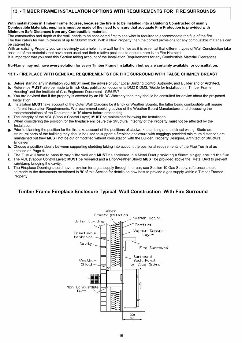
With installations in Timber Frame Houses, because the fire is to be Installed into a Building Constructed of mainly Combustible Materials, emphasis must be made of the need to ensure that adequate Fire Protection is provided with Minimum Safe Distances from any Combustible material. The construction and depth of the wall, needs to be considered first to see what is required to accommodate the flue of the fire. The flue caters for wall thickness of up to 500mm thick. With a New Property then the correct provisions for any combustible materials can be catered for. With an existing Property you cannot simply cut a hole in the wall for the flue as it is essential that different types of Wall Construction take account of the materials that have been used and their relative positions to ensure there is no Fire Hazzard. It is important that you read this Section taking account of the Installation Requirements for any Combustible Material Clearances. Nu-Flame may not have every solution for every Timber Frame Installation but we are certainly available for consultation.
13.1 - FIREPLACE WITH GENERAL REQUIREMENTS FOR FIRE SURROUND WITH FALSE CHIMNEY BREAST a. Before starting any Installation you MUST seek the advise of your Local Building Control Authority, and Builder and or Architect. b. Reference MUST also be made to British Gas, publication documents DM2 & DM3, ’Guide for Installation in Timber Frame Housing’ and the Institute of Gas Engineers Document 1GE/UP/7. c. You are advised that if the property is covered by an NHBC Warranty then they should be consulted for advice about the pro posed Installation. d. Installation MUST take account of the Outer Wall Cladding be it Brick or Weather Boards, the latter being combustible will require different Installation Requirements. We recommend seeking advise of the Weather Board Manufacturer and discussing the recommendations of the Documents in ‘b’ above before proceeding e. The integrity of the VCL (Vapour Control Layer) MUST be maintained following the Installation. f. When considering the position for the fireplace enclosure the Structural Integrity of the Property must not be affected by the Installation. g. Prior to planning the position for the fire take account of the positions of studwork, plumbing and electrical wiring. Studs are structural parts of the building they should be used to support a fireplace enclosure with noggings provided minimum distances are maintained but they MUST not be cut or modified without consultation with the Builder, Property Designer, Architect or Structural Engineer. h. Choose a position ideally between supporting studding taking into account the positional requirements of the Flue Terminal as detailed on Page 4. i. The Flue will have to pass through the wall and MUST be enclosed in a Metal Duct providing a 50mm air gap around the flue. k. The VCL (Vapour Control Layer) MUST be resealed and a Drip/Weather Shield MUST be provided above the Metal Duct to prevent rain/damp bridging the cavity. l. The Fireplace Opening should have provision for a gas supply through the rear, see Section 10 Gas Supply, reference should be made to the documents mentioned in ‘b’ of this Section for details on how best to provide a gas supply within a Timber Framed Property.
13. - TIMBER FRAME INSTALLATION OPTIONS WITH REQUIREMENTS FOR FIRE SURROUNDS
Timber Frame Fireplace Enclosure Typical Wall Construction With Fire Surround

17
13.2 - FIRE SURROUND REQUIREMENTS (See diagram in Section 13.1) General If a fire surround is being used we supply a Cable Fixing System as Drill Fixing may result in cracking of the back panel, which may not show until the fire has got hot and then cooled down over a number of operations. If the fire is being fitted against a Non Combustible Wall then the Fires Fixing Brackets with Drill/ Rawlplug Fixing Must be used and Not the Cable Fixing System. Always Ensure The Fixing Points are Robust and Secure.
See the Wall Fixing and Cable Fixing Diagrams on Page 20.
a. If the Fire is to be fitted with a purpose made Fire Surround it MUST have a temperature rating of 150ºC.
Where a natural material Fire Surround is to be used, due to the possibility of cracking, we recommend that the Back Panel of the
Surround is made of 3 pieces with a top and sides. Some back panel materials claiming a 150ºC rating may still not withstand the
temperature variations created by this high efficient output fire and again we would recommend a 3 piece back panel. b. The Fire requires a non-combustible hearth of at least 12mm thick if the hearth as an upstand it must not be higher than 15mm otherwise the Controls Door will be able to be opened. c. The surface of the hearth must stand at least 50mm above the floor level. d. The hearth must project at least 300mm in front of the fireplace opening and 150mm either side (700mm minimum hearth width). e. The base of the Hearth level and square to the face of the Firesurround Back Panel. f. There must be a minimum flat surface around the Fireplace Opening allowing 630mm high by 635mm wide. g. The Fire Surround/Back Panel must be fully sealed to the Fireplace. h. The Fireplace Opening should have provision for a gas supply through the rear, see Section 10 Gas Supply. i. . Dependant on the Control specified the fire may be fitted with Electronic Equipment, which is sensitive to dampness and high humidity so
it is very important that any rendering/building work is allowed to thoroughly dry out before Installation.
! IMPORTANT NOTE ! Dry lined walls - ensure that any air gaps between the back of the plasterboard and wall are sealed
around the builders opening or fireplace as this can cause overheating of the wall, wall staining and re-duce the heat output of the fire.
! IMPORTANT NOTE ! Ensure the VCL (vapour Control Layer) is resealed as it will be affected by the Installation.
13.3 - FALSE CHIMNEY BREAST APPLICATION a. If it is decided to use a false Chimney Breast to accommodate the fire then the details for materials, sizes, clearances are as detailed above and the diagrams on the previous page. b. The void around the flue must not be packed with insulation and we also recommend that ventilation openings/grilles are added to ventilate the void of the False Chimney Breast at high and low Level. This will allow the cooler room air to circulate around the void of the Chimney Breast, which will reduce temperatures and assist with wall coverings applied to the Chimney Breast.
13.4 - CLEARANCES TO COMBUSTIBLE MATERIALS AND SHELVES a. A non combustible shelf can be fitted above the fire and should be positioned at least 95mm above the builders opening. We recommend the depth of the shelf should be a maximum of 75mm as anything deeper will reduce convection air and the efficiency of the fire. For deeper non-combustible shelves they must be raised a further 25mm for every extra 25mm of depth. b. A 150mm combustible shelf can be fitted above the fire but must be positioned at least 250mm above the builders opening 750mm minimum from the hearth. For deeper combustible shelves they must be raised a further 25mm for every extra 25mm of depth. c. Any combustible sidewall must be 700mm central about the flue, however with a combustible fire surround with side walls deeper than 150mm this distance must be increased by 25mm for every extra 25mm of depth. d. With all heating appliances, soft furnishings, decorations and wall coverings may discolour or scorch if placed too close. e. No combustible material, e.g. curtains must be closer than 500mm to the fire. f. Any combustible wall claddings (wall paper) must be cut back centrally about the flue to 620mm high and 560mm wide. g. Due to the heat output of the Fenton Balanced Flue it is not recommended to use blown vinyl wall covering around the fire.
13.5 - CUTTING THE HOLE FOR THE FLUE With an installation into an existing property, (as apposed to a new build), where the internal wall structure will need to be checked for the positions of Combustible Materials by removing part of the internal wall we recommend that the hole position is determined from inside, the following Notes will assist: a. With a Timber Frame House it is recommended to firstly determine the best position for the fire/flue ideally between supporti ng studs and check for any services like electrical wiring or plumbing. b. The flue is 150mm in diameter, and a hole is required providing sufficient clearance, we recommend 160mm diameter minimum. c. We recommend that you determine the hole position by pilot drilling from the inside before removing any of the internal wall. With hole position now know on the outside wall you can cut the hole knowing its in the correct position. a. If cutting the hole with a core drill as the outside wall is brick work ensure your cutting into solid material as it may wander. b. Partially drill the hole and then check the fit of the flue before finishing,( a Wall Plate is provided for the outside). c. For cutting out the hole with a chisel, first firstly follow step ‘c’ to find a centre then mark out the hole and then use small holes around the hole before cutting out with the chisel and making good the hole,( a Wall Plate is provided for the outside). d. Ensure the hole is horizontal, round and straight. e. Refer to Section 13.1 for requirements for the internal wall structure and protections required for combustible materials. f. Any internal plaster board typical to a dry lined property should be cut back 25mm around the flue, e. g. 210mm diameter.
NOW PROCEED TO SECTION 14 - PREPARING THE FIRE & FLUE.
Dry Lined Internal Walls with Cavity
Cavity Sealed Off 100mm away from Flue
Combustible Shelf Minimum Height
Non Combustible Minimum Height
Plaster Board Cut Back 25mm Around Flue

18
14. - PREPARING THE FIRE. The Fenton Case should have already been removed so again using the Screw Driver Provided Remove the Glass Panel Door by unscrewing the special 5 Countersunk Screws and set aside in a Safe Area.
14a.- Fitting The Silicone Sealing Strip to Fire a. The Silicone Foam Seal is provided to prevent heat escaping at the back of the fire case. Take the self adhesive silicone sealing strip from the fitting kit and neatly apply to the back flanges of the fire case (as close to the edge as possible), cutting to the appropriate lengths as required, then set aside. (Note: Lay the case Down as it could tip over and get damaged).
14b. - PREPARING THE FLUE . 14.1 - DETERMINING THE FLUE LENGTH
4.1 - DETERMINING THE FLUE LENGTH a. The Standard Flue Length supplied caters for a maximum wall thickness of 500mm, and a Minimum Wall thickness of 93mm. (The Total Flue Length Including End Terminal = 630mm). b. To find the flue length required in your application, measure the Wall Depth from the Front Face of the Fireplace to the Outside Wall. Note: If The Outer Wall isn’t flat measure to the highest point. Now take your flue wall length dimension and add 130mm to cater for the length of the End Terminal and this will provide the flue length you require and provide the length of flue you will need to cut off the flue. See Diagram with Example. c. Now measuring from the Terminal End of the Flue mark the cut off dimension, position the cutting aid in the flue central about the cut line and cut the flue, ensuring it is cut square; remove any sharp edges. IMPORTANT: Remove the Cutting Aid Material from inside the Flue.
d. With the flue at the correct length and when the fire is fitted there should be 130mm of Flue Terminal Outside The Wall and the screw holes for fixing the Wall Plate should line up with those in the Flue Terminal. See photographs on page 20.
! IMPORTANT NOTE! NONE OF THE SQUARE HOLES IN THE FLUE TERMINAL MUST BE WITHIN THE WALL.
! TIP ! To provide a good square cut of the flue, place marks around the flue and using a tape measure coiled around the flue mark a
continuous line which will be easier to follow when cutting.
! IMPORTANT NOTES! a. Numerous problems occur because the cutting aid is not removed after cutting the flue. b. Numerous problems occur because the correct length of the flue is correctly determined and the square cut outs in the flue terminal are not outside the wall. Check that the Wall Plate screws can be fitted into the holes in the Flue. c. Do NOT FORCE the flue when engaged into the flue spigot; it goes in just 40mm up to a stop and if forced will block off the flow creating a poor flame picture and overheating if pushed in too far.
FLUE LENGTH DIAGRAM – EXAMPLE To Determine the flue length required and working through the flue hole you have already cut determine the wall thickness by measuring from Face of Fire Surround Back Panel, (or the Wall the Fire is to be Installed against) to the Outside face of the Outer Wall. Example Depth or Wall = 144mm. Now Add the Length of the Flue Terminal 130mm + 144mm = 274mm. Now Measuring from the Terminal End of the Flue, Mark a Line 274mm around the Flue. As a general check this should leave 356mm of Flue to be Cut Off. Note: If the Outer Wall Isn’t Flat Always Measure to the Highest Point as a Wall Plate is Provided.
Cutting Aid
Outside Wall
Inside Wall
Inside Wall to Outside Wall
Dimension

19
DO NOT REMOVE THE PRESSURE RELIEF DOOR CARDBOARD FITMENT AT THE TOP OF THE FIRE AT THIS STAGE.
15.1a - If The Fenton Balanced Flue as a pressure relief system/door to protect against issues with delayed ignition.
15.2 - FITTING THE FIRE - reference should be made to the Cable Fixing Diagrams on the next page.
! IMPORTANT NOTE ! TAKE GREAT CARE WHEN WORKING INSIDE THE FIRE NOT TO MARK THE CERAMIC LINING PANELS.
a. Using a Dust Sheet or equivalent protect the area around the Fire Installation. b. The Glass Panel should have already been removed however if not using the Screw Driver provided remove the 5 special countersunk
screws at the Bottom and Sides Securing the Glass Panel then tilt the Glass Panel outward slightly at the base then slide down to remove. c. Now with the fire upright on its Base, remove the 4 screws holding the Burner/Control Assembly at the 4 corners taking care not to mark
the liners. With the Thermatronic/High Level Controls remove the Heat Shield; a single screw fixing at the right. Carefully lift the Burner Assembly upward then roll out from the back to remove, taking care not to Mark the Liners. If the fire is fitted with the Thermatronic Control it will be necessary to pull the Receiver Box and Infrared Sensor off its Velcro Pads. If fitted with the High Level Control then pull the Battery Box off its Velcro Pad. d. Push the Flue onto the Spigots at the rear of the fire and IMPORTANT, ensure that ‘TOP’ marked on the end of the Flue Terminal is at the
top centre; using the drill provided and with the flue level, mark and drill the three holes around the Spigot. Secure the flue with the Screws provided and then seal around the flue/spigot with the Sealing Tape also provided. e. The Method for Securing the fire be it Cable Fixing or Wall Fixing system should now be considered. See Diagrams on the Next Page. Note: The Cable Fixing System should be used when the fire is being fitted with a Surround Panel. For cable fixing go to ‘g’. The Wall Fixing System should Only be used when a Surround Back Panel is not being used. For wall fixing go to ‘f’. IMPORTANT: Drill through a Surround Back Panel could result in cracking not just when being drilled but over time. Nu-Flame will NOT accept Responsibility for Cracks Caused Due To Drilling Surround Back Panels. IMPORTANT : Do Not Force The Flue In Too Far Or Past It’s Stop As It Will Block Off The Flow Causing Overheating. f. For Wall Fixing it will be necessary to position the fire with flue fitted into the opening to enable the holes to be marked through
the Fixing Brackets before drilling and fitting Rawl Plugs ready for securing the fire, now proceed to ’j’. Note: When sliding the fire with flue into the Hole in the Wall take care not to damage the Hearth g. For Cable Fixing there are 2 cables supplied; 1 to be used each side of the unit. Working at 360mm centres in the fireplace enclosure drill the lower holes 27mm up from the base and drill the higher holes 510mm up from the base (see Cable Fixing Diagrams on
next page). Secure the 4 Eyebolts supplied with the Rawl Plugs to the back of the fireplace. Ensure the Eyebolts are fully screwed in. IMPORTANT NOTES: ENSURE THE MATERIAL THE EYEBOLT/RAWPLUG IS FIXED INTO IS SOLID AND SOUND. i) If the fixing is not sound the Rawlplug/Eyebolt will be pulled out and the fire will not be sealed to the Fireplace Opening. II) The head of the eye bolt must be level or below the front face of the surround back panel, for this reason it may be necessary to recess the head of the eye bolt into the brickwork.. h. There are 2 cable attachment tabs on the top of the main casing; 1 each side at the rear. They are part of the folded down lip of the case,
prize these up with a screwdriver to enable them to be used. Feed a cable downwards through each cable attachment point ready for the next stage of Installing the fire.
Note: When sliding the fire with flue into the Hole in the Wall take care not to damage the Hearth i. IMPORTANT : Do Not Force The Flue In Too Far Or Past It’s Stop As It Will Block Off The Flow Causing Overheating. j. When fitting the fire into the Hole in the Wall take care to not damage the Hearth. Now rest the Fire on the Hearth so that you can
still gain access to the cables and eyebolts behind the fire. Feed the cables though the eyebolts on either side and then through the holes in the back of the fire near the base.
k. Lifting the fire slightly at the base so as to not damage the Hearth slide the Fire/Flue into the hole guiding the flue into the hole until it is part way (leaving the fire sticking out approximately 50mm) ensuring the gas supply pipe and isolation/pressure test elbow clears through the cut out in the rear of the Main Casing. While sliding the unit further into the Fireplace Opening pull on the excess cable.
l. Now again lifting the Fire slightly, slide it home ensuring that the sealing strips on the underside/rear of the front of the Fire stay in position to make a seal against the fireplace enclosure. While sliding the unit into the Fireplace Opening pull on the excess cable.
m. The Cable Fix Adjuster and Lock Screw (see Cable Fixing Diagrams on next page) can now be fitted onto the cable and tightened up to tension the fire back into the fireplace to secure the fire.
It may be easier to work through the base of the Firebox. Take care not to damage the Liners. Surplus fixing cable MUST NOT be cut off and must be tucked back through the central hole in the Back of the Fire. This is particularly important with the Thermatronic Control System to keep the cables away from any electronics.
n. With fixing if any of the silicone sealing strips are not compressed and/or if there are gaps they must be filled with a suitable sealant, fireclay or high temperature silicone.
15. FITTING THE FIRE
Do not remove the Pressure Relief Door Cardboard Packer and Label yet. The Packer is to hold the Pressure Relief Door Closed at
this stage.
View Pressure Relief Door through here.

20
o. Now on the Outside check that the End Terminal part of the Flue is clear of the hole = 130mm of Flue, the Terminal should be clear of the wall – NOT WITHIN THE WALL., (ensure all the square cut outs are outside the wall), See photograph below. p. Adhere Sealing Foam to back of the Wall Plate (see Note below). Fit and secure the Wall Plate to the Flue through the holes provided in the flue terminal and seal to the Wall with the Stainless Steel Screws provided. Note: To prevent the ingress of water Sealing Foam has been supplied for the Wall Plate, if this does not provide an adequate seal with the wall then any gaps must be filled with a waterproof silicone sealant or mastic. Note: With the flue at the correct length and when the fire is fitted there should be 130mm of Flue Terminal Outside The Wall and the screw holes for fixing the Wall Plate should line up with those in the Flue Terminal.
! IMPORTANT NOTE ! NONE OF THE SQUARE HOLES IN THE FLUE TERMINAL MUST BE WITHIN THE WALL.
q. Refit the Burner Assembly and secure with 4 screws, reposition the Thermatronic (Receiver Box and Infrared Sensor) or for High Level Control the Battery Box onto their Velcro Pads if applicable. Reposition Receiver/Battery Box under Heat Shield. r. Now Remove the Pressure Relief Cardboard Packer and Label at the Top of the Fire.
Ensure the Pressure Relief Door has remained closed (see photograph on previous page). s. Connect the isolation/pressure test elbow to the control valve and with it fully open check the joint for gas soundness. t. Check that all gas connections are sound. The appliance has been factory tested; however the connections may have been disturbed in
transit or storage.
! IMPORTANT NOTE ! Always reseal the pressure test point and check that it is gas tight.
(This accounts for a lot of recalls.)
WALL FIXING AND CABLE FIXING DIAGRAMS
When Cable Fixing If Necessary Recess The Eye Bolt To Ensure It Doesn’t Foul On The Surround Back Panel.
Side View of Cable Fixing System
Cable Fixing Hole Positions
360mm
510 mm
27mm
Top of Hearth
Side View of Wall Fixing System
Prize Tab Away From Case
Eye Bolts
Eye Bolts
Spacer/Fixing Brackets
Spacer/Fixing Brackets
Fixing Screws & Rawl Plugs

21
16. - ARRANGEMENT OF THE FUEL EFFECT (COALS or WOOD) Remove all the Fuel Effect parts & familiarise yourself with each part. The Fuel Effect depends on the one ordered be it the Coal Fuel Bed or the Wood Fuel Bed. Both the Coal and Wood Fuel Effects have a common Back Matrix (sits on a Matrix Tray) and a common Front Matrix. The additional Fuel Effect Parts are detailed below. Coal Fuel Bed Matrix Tray (Common Part). Back Matrix (Common Part). Front Matrix (Common Part). The Coal Effect consists of a Rear Coal Cluster and a Front Coal Cluster together with the following loose coals, 3off ‘C’ marked Coals, 5off ’H’ marked Coals and 6off ’B’ marked Coals. Wood Fuel Bed Matrix Tray (Common Part). Back Matrix (Common Part). Front Matrix (Common Part). The Wood Effect consists of a Rear No1 Wood, a Front No2 Wood together with 8off Smaller Wood pieces numbered 3 to 6.
! TIP ! TAKE CARE NOT TO DAMAGE THE LINER PANELS INSIDE THE FIRE WHEN FITTING THE FUEL BED .
The following stages, ’a’, ’b’ and ’c’ for fitting the fuel bed apply to both Coals and Wood Effects a. Fit the Matrix Tray. b. Fit the Rear Matrix on top of the Matrix Tray. Ensure it is sat up against the back and with ‘TOP’ facing you.
c. Slide the Front Matrix in front of the burner as shown with ‘FRONT ‘ facing you.
Health & Safety Advice Refractory Ceramic Fibre (RCF)
Advice when working with Fuel Bed Components including Installing, Servicing and Disposal. The Fuel Effect parts and possible Linings of this fire are made from Refractory Ceramic Fibre (R.C.F.) a Class 2 Carcinogen which is a material designed for this Application. Excessive exposure to these types of materials may cause temporary irritation to eyes, skin and respiratory tract. Therefore take care when handling these articles to ensure dust is kept to a minimum. It is not necessary to wear protective clothing when handling these articles but we do recommend you follow the normal hygiene rules of not smoking, eating or drinking in the work area, and always wash your hands before eating or drinking. To minimise the release of RCF fibres during installation and servicing a HEPA filtered vacuum is recommended to remove any dust accumulated in and around the fire both before and after working on it. When Servicing and if replacing these parts we do not recommend they are broken up but are sealed within a heavy duty polythene

22
16.1 - ARRANGING the COAL EFFECT
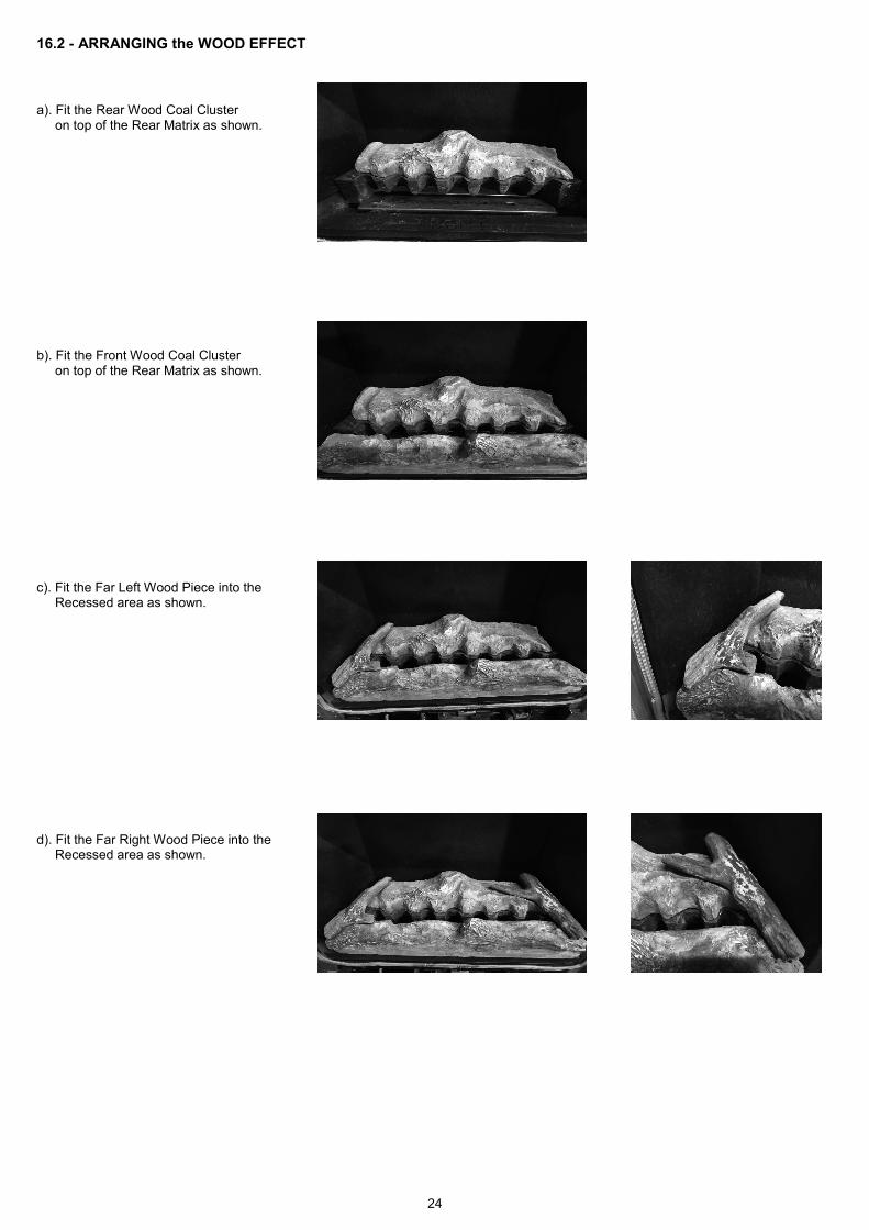
a). Fit the Rear Coal Cluster on top of the Rear Matrix as shown.
b). Fit the Front Coal Cluster on top of the Front Matrix as shown.
c). Fit 3off ’C’ coals up against the Rear of the fire as shown. Set the ’C’ indent facing the back.
d). Fit 2off ’B’ coals in the pocket in the Rear Corners as shown.
e). Fit 2off ’H’ coals in the pockets in the Front Corners as shown.

23
16.1 - ARRANGING the COAL EFFECT - continued
f). Fit 2off ‘B’ Coals in the front central pockets as shown.
g). Fit 2off ‘H’ Coals in the front pockets angled outward as shown.
h). Fit 2off ’B’ Coals on Top of the Front coals already fitted as shown.
i). Fit 1off ’H’ Coal laid on Top of the front coals already fitted as shown.
Finally adjust the coals to ensure they are located correctly, stable and not overhanging the pockets. Also ensure non of the identification letters stamped on the coals are visible.
j). Before fitting the glass panel with the 5 special countersunk screws and screw driver provided, check the condition of the glass and ensure it is free from cracks or chips. NOTE: BEFORE FITTING THE GLASS PANEL IF A CONTEMPORARY TRIM IS TO BE FITTED THEN THE CURVED DÉCOR TRIM WILL HAVE TO BE FITTED - SEE 15.1b
Most Important: Ensure it is clean and free of any finger marks.
24
16.2 - ARRANGING the WOOD EFFECT a). Fit the Rear Wood Coal Cluster on top of the Rear Matrix as shown.
b). Fit the Front Wood Coal Cluster on top of the Rear Matrix as shown.
c). Fit the Far Left Wood Piece into the Recessed area as shown.
d). Fit the Far Right Wood Piece into the Recessed area as shown.
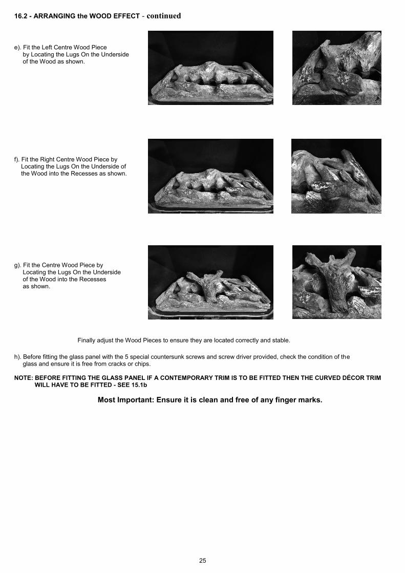
25
16.2 - ARRANGING the WOOD EFFECT - continued
e). Fit the Left Centre Wood Piece by Locating the Lugs On the Underside of the Wood as shown.
f). Fit the Right Centre Wood Piece by Locating the Lugs On the Underside of the Wood into the Recesses as shown.
g). Fit the Centre Wood Piece by Locating the Lugs On the Underside of the Wood into the Recesses as shown.
Finally adjust the Wood Pieces to ensure they are located correctly and stable. h). Before fitting the glass panel with the 5 special countersunk screws and screw driver provided, check the condition of the glass and ensure it is free from cracks or chips. NOTE: BEFORE FITTING THE GLASS PANEL IF A CONTEMPORARY TRIM IS TO BE FITTED THEN THE CURVED DÉCOR TRIM WILL HAVE TO BE FITTED - SEE 15.1b
Most Important: Ensure it is clean and free of any finger marks.

26
17 - TESTING, COMMISSIONING & USE ! IMPORTANT NOTE ! NOW REMOVE THE PRESSURE RELIEF CARDBOARD FITMENT AT THE TOP OF THE FIRE.
! IMPORTANT NOTE ! During its first period of use any protective coatings and oils will burn out of the fire and it is wise to venti-
late the room for the first hour; also advise the customer that this may persist for the first few days until the fire is fully burnt-in.
17.1 - LIGHTING THE FIRE a. Reference to Section 2 in the Users Instructions ’Lighting & Controlling the Fire’ will show how to light and operate the fire. b. Check that the supply pressure to the fire is at the pressures required, 20mbar (Natural Gas G20) or 37mbar (Propane G31) when set at
high.
! IMPORTANT NOTE ! Ensure that the pressure test point used is sealed and gas tight.
17.2 - FITTING THE OUTER CASE (Take Care With The Case As It Can Tip Over)
b. Check that the case foam seal is up against the wall/back panel specifically at the top and if not adjust the feet under the legs. c. Secure with the 2 screws provided.
17.3 - FIREGUARDS a. A fireguard is not supplied with the appliance however it is recommended that a fireguard is fitted if the fire is to be used in the presence of young children, the elderly, the infirm and pets. b. For Hole in the Wall Installations it is recommended that a means, (tactile separator/shelf or guard) is provided to give abrupt warning to a person moving inadvertently towards the fire.
18 - BRIEFING THE CUSTOMER a. The installer should brief the customer on the Operation of the Control System and all aspects of the User Instructions. b. The instructions/with the Case/Glass Panel release Screw Driver should be handed to the customer for their safe keeping and future servicing. c. Show the customer how the Case and Glass Panel can be removed for cleaning with the screw driver provided. d. For Customers who have purchased the Thermatronic or High Level Controls explain and demonstrate that the batteries in the receiver and handset , (Thermatronic) or Battery Box (High Level), should be replaced with good quality ones annually as the fire may stop
working part way through the season. e. The customer should be briefed on the need for regular servicing; this will normally be once a year.
Note: Advise The Customer that Marks on the Glass Panel are Not Covered by the Manufactures Warranty. f. Advise the customer that, apart from batteries for the High Level and Thermatronic System, there are no user replaceable parts in the fire
but for servicing and spares to contact the local Nu-Flame Stockist. g. Advise the customer that under no circumstances must the fire be used without the glass panel fitted or if it is in any way chipped, cracked
or damaged. h. Advise the Customer that the fire is fitted with a Safety Pressure Relief System and if the fires ignition should ever become delayed, or noisy then the fire NUST NOT be used until checked by a Qualified Engineer/Installer. i. Advise the Customer that the Glass Panel on the fire will become very hot during operation and that we recommend that a fireguard is fitted if the fire is to be used in the presence of young children, the elderly, the infirm and pets. j. Explain that due to the High Efficiency of the Fire other than the Control Knobs/Switch, Ashpan Knob and surrounding areas: All surfaces are classified as Working Surfaces and will be very hot when the fire is in operation.
! IMPORTANT NOTE ! THE GLASS PANEL ON THIS FIRE WILL BECOME VERY HOT DURING OPERATION ENSURE THE CUSTOMER IS ADVISED OF THIS. ! IMPORTANT NOTE ! WE STRONGLY RECOMMEND THE FITTING OF A FIREGUARD WHEN THE FIRE IS USED IN THE
PRESENCE OF YOUNG CHILDREN, THE ELDERLY, THE INFIRM & PETS.
a. Offer the Case up to the fire and lift it up at the back clear of the securing brackets then lower to engage. Centralise the case and ensure it is sitting down on the hearth.
27
19 - SERVICING
The Matrix in the fire is a Moulded Ceramic Fibre component incorporating Silicone Binders and you may notice that it develops cracks during operation. This is natural shrinkage caused by exposure to high temperatures and is quite normal for the material and will in no way affect the operation of the fire.
19.1 - GENERAL Note: Servicing must be carried out by a registered installer. a. The fire does not have to be removed for Servicing. b. Check the operation and ignition of the fire before servicing. c. Ensure the fire is cold before proceeding. d. Lay a dust sheet on the floor before proceeding. e. Carry out a gas soundness test before servicing. f. Remove case by opening the Controls Door and then firstly remove the 2 screws at the left and right sides. Secondly lift the case up at the back and remove. Place in a convenient place with the 2 screws. g. Turn off the gas supply to the fire at the isolation/pressure test elbow. h. Remove the 5 special countersunk screws holding the glass door panel, slide it downward to remove, check for any damage. i. Now remove the Fuel Bed Components and place in a safe location to prevent any damage, taking note of their placement. j. If any parts need replacing, use only genuine parts supplied by Nu -Flame Ltd. Some components may look similar to those used in other gas fire, but these are not necessarily the same due to performance variations and must not be used. This applies particularly to the Flame Failure Pilot System, Gas Control System and Ceramics. k. Disconnect the gas pipe to the control.
IMPORTANT: Always Lay The Case Down To Prevent It Being Damaged.
19.2 – ANNUAL SERVICING
Carry out the operations in 19.1 General before proceeding Now, working inside the fire, remove the Rear Matrix Support Bracket then the 4off No6 screws holding the Burner/Control Assembly, 2 at the back and front. Carefully lift the Burner Assembly upward then roll out from the back to remove, taking care not to Mark the Liners. This will now allow access to all gas carrying parts for maintenance checks, fault finding and or replacement. l. Brush clean the burner and pilot area of dust or debris; check that the aeration hole in the pilot is clear of dust. m. Refit in reverse order; brushing the Coals/Woods clean of any soot, checking gas soundness and ignition as detailed in the relevant Sections. n. Check that the Flue Terminal and Guard are not damaged or covered in any way. o. Clean the glass panel and check it for any cracks or chips before sealing the door with the 5 special countersunk screws. p. With the 2 Remote Control Systems, Always exchange the Batteries in both the Handset and Receiver. q. With the 2 Remote Control Systems ensure they are operational with the Handset.
ALWAYS CONDUCT A GAS SOUNDNESS CHECK AFTER SERVICING.
ALWAYS RESEAL THE PRESSURE TEST POINT AND CHECK THAT IT IS GAS TIGHT. (This accounts for a lot of recalls.)
ALWAYS CHECK THAT THE GLASS IS CLEAN AND FREE FROM FINGERPRINTS. (This accounts for a lot of recalls.)
IF THERE IS ANY DAMAGE FOUND ON THE GLASS PANEL IT MUST BE REPLACED BEFORE THE FIRE IS USED.
Note: Marks on the Glass Panel are Not Covered by the Manufactures Warranty.
20 - FAULT FINDING GUIDE, SYMPTOMS AND POSSIBLE CAUSES Important: In instances where it is indicating that the main control system needs changing, (specifically the 2 Remote Control Systems),
you should investigate returning the whole Burner Control System Assembly to Nu-Flame for Rectification as this could be the least cost option.
a. Prior to any Servicing ensure that you have carried out the procedures in Section 19.1 General (Servicing). b. Check the supply pressure at the isolation elbow.
c. Important: With the 2 Remote Control Systems always change the batteries before carrying out any Fault Finding. 20.1 - RESETTING THE HAND HELD RADIO FREQUENCY CONTROL SYSTEMS
Full Reset - If a new handset is obtained the control system will need to learn the handset’s unique code via a Full Reset. Also, if the fire is not working and the Basic Reset (described on page 8) has not worked a Full Reset can be carried out: a. Open the Controls Door and locate the electronic Receiver Box. b. Locate the Reset Hole on the side of the Receiver and using a pen press and hold in the Reset button until you hear two beeps. c. The first beep is short and the second beep is long. After the second beep release the Reset Button. d. Now on the Handset, within the next 20 seconds press and hold the Small Flame Button until you hear two additional short beeps confirming the code is set in the Receiver. e. If you hear one long beep the Code as not been set so repeat the procedure. f. If the Handset still does not work check the wiring and or replace the Receiver and Handset .
20.2 - NO SPARK IGNITION a. Replace the batteries in the receiver and handset. b. Check there is no dust/debris shorting out the electrode or blocking the gas from the pilot. c. Check the condition of the Ignition lead and ensure it is connected to both the ignition electrode and receiver. Check that the Ignition
lead is not trapped and or shorting, replace if required. For the Manual System this will involve a new control. d. Check the condition of the Electrode, if it sparks intermittently it may be cracked, replace.
See Next Page
28
e. Check that gas is flowing from the pilot during the ignition sequence. Clean or Replace as required. f. For the Remote Control Systems only, listen to the control to hear if the pilot gas solenoid is opening. Change the receiver, and the hand-
set at the same time and/or gas control. Refer to Section 22 for Cable connections diagram. Also see Important Note at the beginning of this Section 20, concerning possibly returning parts as the cheaper option.
20.3 - PILOT GOES OUT AFTER FIRST LIGHTING a. Check there is no debris blocking the flame to the thermocouple. b. Check there is nothing covering the terminal guard/flue on the outside. c. Check the thermocouple is in the correct position because although the fixing nut may seem tight and secure, the Thermocouple may have slipped down. Slacken the fixing nut, reposition then retighten. With the Thermatronic System check all connections in the Thermocouple circuit., from the valve, interrupter and wiring connections to the Receiver. d. If the Pilot Flame seems small the Injector may be slightly blocked, replace. e. For the Remote Control Systems only, listen to the control to hear if the pilot gas solenoid is opening. Change the receiver and at the same time and/or the gas control. Refer to Diagram for Cable connections in Section 22. f. Also see Section 21.5. g. Specific to new installations and by far the highest cause of this type of fault. Typically the pilot and main burner lights with the door open but goes out when the door is closed. Possibly part or all of the cutting aid has been left in the flue after cutting.
20.4 - PILOT LIGHTS BUT MAIN BURNER DOES NOT LIGHT a. With All Control Systems listen to hear if gas is flowing into the main burner. b. Check there is no dust or debris blocking the flame from the pilot to the main burner. c. With the 2 Remote Control Systems check that both Control Knobs are in the on position, fully turned anti clockwise. Also check ‘e’ before determining the action required. d. With the 2 Remote Control Systems check if the main control knob on the control is turning to the high setting and listen to hear if the valve is opening. If not change the Handset & Switch (which ever applies) and at the same time the gas control. For removal of the systems refer to the Diagram for Cable connections in Section 22. Also check ‘g’ (below) before considering replacing any parts. You should also consider the Important note in 21.1. e. With the 2 Button High Level Control it is possible for the Main Burner to light when first lit after lighting the Pilot but then the Push Buttons do not operate the control. Operate the bottom button and listen to see if the Control Knob turns. If it does not then change the batteries, if still a problem change the Switch Assembly as detailed in ‘f’. f. For removal/replacement of the 2 & 3 Button Switches first remove the 2 screws retaining the Switch Shield, remove the 2 screws retaining the Switch Assembly. Disconnect the push on wire connections at the control. Remove the switch and wires and replace with a new component in reverse order. g. All Control Systems have a Pressure Test Point to allow the Burner Pressure to be checked to confirm if gas is flowing from the control. On the Manual Control it is visible at the front left of the control. On the 2 Remote Control Controls it is the left pressure test point facing the front. Ensure the pressure test point screw is fully closed after checking. h. Check if the main injector is blocked. Clean or Replace. i. Also see Section 21.3.g.
20.5 - PILOT FLAME SHORTENS, OR GOES OUT WHEN MAIN BURNER IS SELECTED a. Monitor the supply pressure at the isolation elbow as the main burner lights. If pressure drops significantly, check gas pipe sizing and quality of pipe bending. Check for debris in the gas supply and or gas filter if fitted. b. Check that another appliance is not affecting the gas supply pressure. c. Check the points raised in Sections 21.3 and 21.4.
20.6 - POOR FLAME PICTURE a. Check the supply pressure is correct at the isolation elbow. If the pressure is low, check gas pipe sizing, quality of pipe bending. Check for
debris in the gas supply and or gas filter if fitted. b. All Control Systems have a pressure point to allow the Burner Pressure to be checked. On the Manual Control it is visible at the front left of the control. On the 2 Remote Control Controls it is the left pressure test point facing the front. Ensure the pressure test point screw is fully closed after checking. You may wish to check ‘c’ first. c. Check that another appliance is not affecting the gas supply pressure. d. Check that the Flue Terminal and Guard are not damaged or covered in any way. e. Check the Fuel bed layout is as detailed in Section 16. f. Check that none of the fuel cutting aid as not been accidently left in the flue. g. Check that the flue pipe as not be forced into the flue spigot too far, (over 40mm) and past its stop blocking off the flue flow.
20.7 - FIRE OPERATES FOR A WHILE THEN GOES OUT a. Check the supply pressure is correct at the isolation elbow with all other gas appliances working. If the pressure is low or fluctuating up
and down check gas pipe sizing, quality of pipe bending. Check for debris in the gas supply, pilot pipe and or gas filter if fitted. b. Check the points raised in Sections 21.2 and 21.3. c. For the Manual Control check that the Thermocouple Electrical Connections is tight and check the pilot flame size. d. For the 2 Remote Control Systems check that the Control is functioning correctly as detailed in Section 2.4 and also specifically check the Thermocouple Electrical Connections and Pilot Flame size. e. Check that the Fuel Bed Matrix’s and the Rear Matrix Support are fitted correctly. f. Check that the Flue Terminal and Guard are not damaged or covered in any way. g. Also see Section 21.3.g. h. See 21.6 g.
20.8 - THE RADIO FREQUENCY CONTROL SYSTEM DOES NOT OPERATE a. Check the control is being correctly operated - see Section 2.4 b. Check for error messages and check batteries - see Section 2.5 c. Reset the Mertik Maxitrol Logic Circuits - see Section 2.6
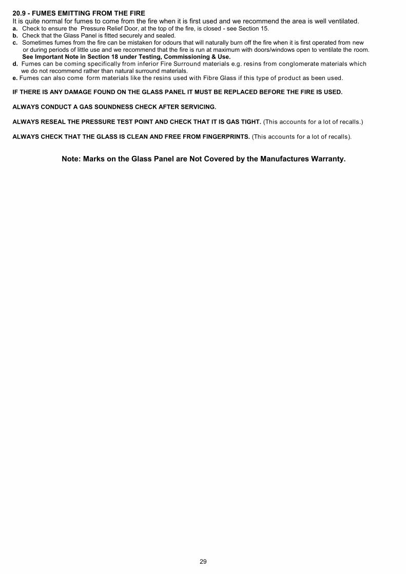
29
20.9 - FUMES EMITTING FROM THE FIRE It is quite normal for fumes to come from the fire when it is first used and we recommend the area is well ventilated. a. Check to ensure the Pressure Relief Door, at the top of the fire, is closed - see Section 15. b. Check that the Glass Panel is fitted securely and sealed. c. Sometimes fumes from the fire can be mistaken for odours that will naturally burn off the fire when it is first operated from new or during periods of little use and we recommend that the fire is run at maximum with doors/windows open to ventilate the room. See Important Note in Section 18 under Testing, Commissioning & Use. d. Fumes can be coming specifically from inferior Fire Surround materials e.g. resins from conglomerate materials which we do not recommend rather than natural surround materials. e. Fumes can also come form materials like the resins used with Fibre Glass if this type of product as been used. IF THERE IS ANY DAMAGE FOUND ON THE GLASS PANEL IT MUST BE REPLACED BEFORE THE FIRE IS USED.
ALWAYS CONDUCT A GAS SOUNDNESS CHECK AFTER SERVICING.
ALWAYS RESEAL THE PRESSURE TEST POINT AND CHECK THAT IT IS GAS TIGHT. (This accounts for a lot of recalls.)
ALWAYS CHECK THAT THE GLASS IS CLEAN AND FREE FROM FINGERPRINTS. (This accounts for a lot of recalls).
Note: Marks on the Glass Panel are Not Covered by the Manufactures Warranty.

30
21 - ENERGY CLASS & PRODUCT FICHE
FENTON BF (Natural Gas) Standard Remote Control
FENTON BF (Natural Gas) Thermostatic Remote Control
Supplier Nu-Flame Limited
Model Fenton BF (NG)
Energy Efficiency Class D
Direct Heat Output 3.4kW
Energy Efficiency Index 76.6
Useful Energy Efficiency at Maximum 87.60%
Useful Energy Efficiency at Minimum 80.0%
The fire must be Installed & serviced by a properly qualified (in
accordance with Local & National Codes) Installation Engineer
and in accordance with these Installation Instructions
Supplier Nu-Flame Limited
Model Fenton BF (NG)T
Energy Efficiency Class C
Direct Heat Output 3.4kW
Energy Efficiency Index 81.6
Useful Energy Efficiency at Maximum 87.6%
Useful Energy Efficiency at Minimum 80.0%
The fire must be Installed & serviced by a properly qualified (in
accordance with Local & National Codes) Installation Engineer
and in accordance with these Installation Instructions

31
21b - ENERGY CLASS & PRODUCT FICHE (Propane Models)
FENTON BF (Propane) Standard Remote Control
FENTON BF (Propane) Thermostatic Remote Control
Supplier Nu-Flame Limited
Model Fenton BF (LPG)
Energy Efficiency Class D
Direct Heat Output 3.3
Energy Efficiency Index 76.0
Useful Energy Efficiency at Maximum 87.0%
Useful Energy Efficiency at Minimum 78.6%
The fire must be Installed & serviced by a properly qualified (in accordance with Local & National Codes) Installation Engineer
and in accordance with these Installation Instructions
Supplier Nu-Flame Limited
Model Fenton BF (LPG) T
Energy Efficiency Class C
Direct Heat Output 3.3
Energy Efficiency Index 81.0
Useful Energy Efficiency at Maximum 87.0%
Useful Energy Efficiency at Minimum 78.6%
The fire must be Installed & serviced by a properly qualified (in
accordance with Local & National Codes) Installation Engineer
and in accordance with these Installation Instructions

32
22 - EU DECLARATION OF CONFORMITY
EU Declaration of Conformity
Name of the Client : Nu-Flame Ltd Address of the Client : Unit 4 : Kimpton Trade & Business Centre : Minden Road : Sutton : Surrey : SM3 9PF Telephone : 020 8641 9992 Manufacturing Location : As above This declaration of conformity is issued under the sole responsibility of the manufacturer above for: Product : Fenton Balanced Flue Certificate Number : 19GR0277/00 The object of the declaration described above is in conformity with relevant harmonized legislation Gas Appliance Regulation (EU) 2016/426 The following harmonised standards and technical specification have been applied:
EN 613: 2001 Independent close-fronted gas-fired type B11, type C11, type C91 and type C31 Heaters. Where the Essential Requirements of the GAR have been met and approved by Notified Body: Responsible Test House : KIWA (Netherlands) Authorized Signature of Manufacturer: Date of Issue: 1st August 2019

33
23. - DIAGRAM OF RADIO FREQUENCY CONTROL SYSTEM

34
Telephone 020 8254 6802 Nu-Flame Warranty and Repair Procedure for The Fenton Balanced Flue. The Nu-Flame Fenton Balanced Flue is guaranteed for 1 year from the date of purchase. During that time our guarantee is to send replacement parts for a fire that proves to have faulty components or workmanship. At our option we may decide to repair, or replace, at no charge a fire that proves to have faulty components or workmanship. Telephone Help Line. In the event of a problem with a fire the first course of action should be to telephone our technical department on 020 8254 6802 during normal working hours 9 - 5.30 Monday - Friday (closed 1 - 1.30). If possible this should be done before the installer leaves site as we may well be able to resolve the problem over the phone, and, in any event it will save the installer a return visit to site. If we are not able to resolve the problem over the phone we will decide the most expedient way of resolving the problem and this is likely to be to send replacement parts. It is possible that we will ask you to return the fire or parts of the fire and if this is the case we will log your details and give you a return reference number. Returning the Fire and parts thereof. After assessment we might consider it best to return part of the appliance, such as the burner only, for testing. In this example the burner can then be thoroughly inspected and any signs of installation faults can be reported back to you. After any repair work is carried out the flow rates can be checked and re-set if necessary in order to fully comply with CE approval. Note: It is a condition of the warranty that you do not return any parts to us unless we request you to do so. For example if we request that the burner only is returned and you send the entire appliance the glass and the fuel bed and other items could be damaged during the return delivery to us. We will not be liable for any such breakages. Under no circumstances should any attempt be made to repair the burner on site without our express knowledge and approval during the warranty period. This guarantee is given subject to the following provisions: 1. That the installation is carried out by a Registered Installer (we may require their registration details). 2. That the appliance is installed and used in accordance with our Installation & User instructions. 3. That the gas supply pressure at the appliance is not more than 3mbar below the gas pressure stated on the data plate when the
appliance is running on high flame, with any other major gas appliances also running. 4. That the fireplace and flue system conform to relevant local codes, building regulations and British Standards. 5. This Guarantee is not transferable and relates to the original installation only. 6. The appliance has not been subject to misuse or accident or been modified or repaired by any person other than the authorised
employee or authorised representative of Nu-Flame Ltd. 7. The Record Data Section on the front of the Installation & Servicing Instructions is to be completed on installation. 8. Nu-Flame Ltd accepts no liability for any consequential loss or damage arising from the use or failure of the product or any information provided, including, but not limited to, economic or financial loss, damage to peripheral equipment or products, loss
of use, productivity or time. 9. That the serial no. data plate on the burner is intact. This guarantee in no way reduces your statutory rights. This guarantee supersedes any previously published guarantees. Chargeable Repairs During And After The Warranty Period If a repair is chargeable during the warranty period, due to installation faults we will inform you and where possible give you a quote, or if this is not possible, a price guide before starting work. We cannot always give a firm cost until we commence the repair as it is not always possible to tell which components have been damaged.