The Design of a Family of Process Compressor Stages · PDF fileOutline •Objectives...
33
The Design of a Family of Process Compressor Stages H. Hazby M. Casey C. Robinson R. Spataro PCA Engineers Limited, UK O. Lunacek Howden ČKD Compressors, Czech Republic
Transcript of The Design of a Family of Process Compressor Stages · PDF fileOutline •Objectives...

The Design of a Family of Process
Compressor Stages
H. Hazby M. Casey C. Robinson R. Spataro
PCA Engineers Limited, UK
O. Lunacek
Howden ČKD Compressors, Czech Republic

Outline
• Objectives
• Master and Derived Stages
• 1D Design Guidelines
• Detailed design
• Manufacture and Testing
• Summary
2

Multistage inline compressors
3
• Used in a wide range of volume flows, pressure ratios and gas properties for
different applications
• Use families of pre-engineered stages to meet individual customer’s requirements
by changing
• Impeller diameter
• Number of stages
• Stage types
• Speed
• Cooling arrangement
• Overall performance is calculated by
stage-stacking of the individual stage
characteristics
• Penalties for ‘failure’ quite high

Objectives
4
• Upgrade the performance of the existing compressor family at Howden ČKD
Compressors
• Choice of master stages and a series of derived stages to adapt these to the
exact flow conditions required
• Cover a range of flow coefficient (𝜙 =4𝑉0
𝜋𝑈2𝐷22) between 0.0075 and 0.15
• Preliminary and detailed design of the
stages
• Performance testing of selected stages
Outline
• Objectives
• Master and Derived Stages
• 1D Design Guidelines
• Detailed design
• Manufacture and Testing
• Summary
5

Master and Derived Stages
6
• For a fixed first stage, the flow coefficient of the downstream stages varies
depending on the machine tip speed Mach number (𝑀𝑢2 =𝑈2
𝑎01)
0.3
0.4
0.5
0.6
0.7
0.8
0.9
0 0.05 0.1 0.15
eta_vld
psi_vld
0.3
1.1
0.8
Flow coefficient f
Polytropic
efficiency (hp )
Pressure rise
coefficient (y)
)1/(12
2
212
2
221
)1(1)/()/(4
n
u
nntttn
MuDm
fff

Master and Derived Stages
7
• Step change in flow coefficient was determined by the Renard R40 series
• 6% ( 1040
) change in flow coefficient between successive stages
• 60 stages to cover the entire range from 0.0075 to 0.15
• Derived stages are trimmed from master stages to achieve intermediate
stages
• Col Charles Renard was a designer of airships for
the French Army in the 1880’s
• He proposed the system of ‘preferred’ numbers that
became ISO 3
• Used it to reduced the number of different balloon
ropes kept on inventory from 425 to 17
• It divides a decade into 5, 10, 20 or 40 steps Col. Charles Renard
(1847-1905)

Master and Derived Stages
8
• Designing new stages for each application is not practicable
• Seven master stages were used to cover the required flow range
• The step size can be smaller at high flow coefficients stages and larger at
low flow coefficients
• Rotordynamic advantage in
switching earlier to shorter low
flow coefficient stages
• Efficiency drop at high flow
coefficients (or more sensitive
to trimming)
Master and Derived Stages
9
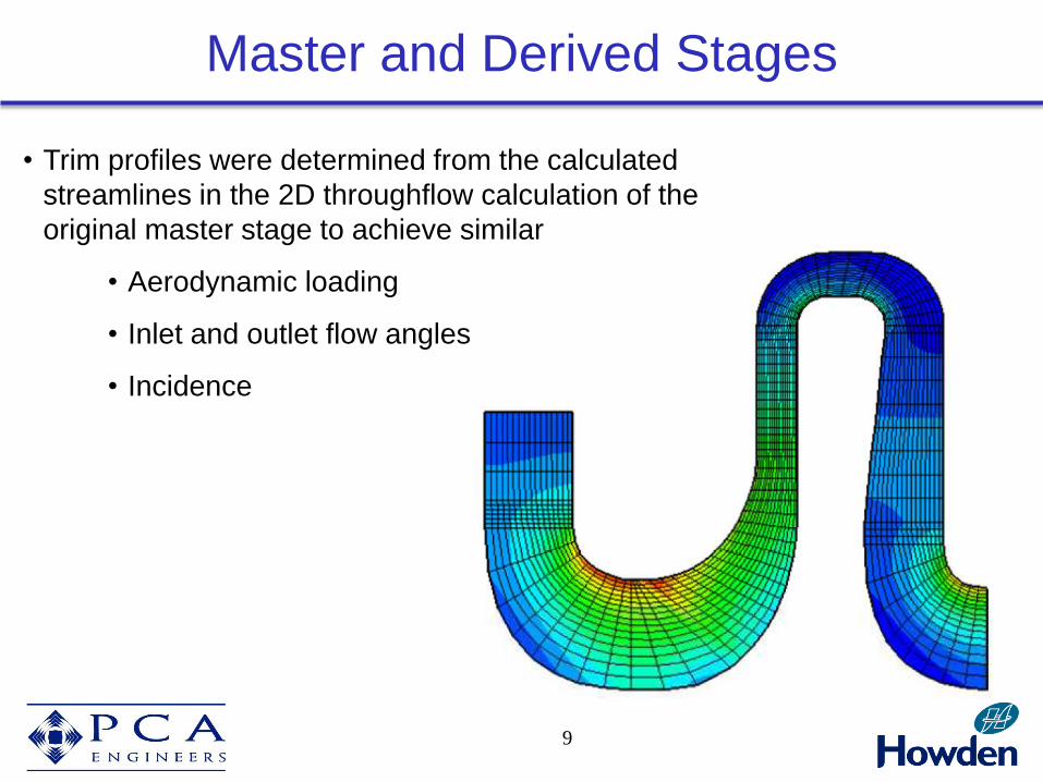
• Trim profiles were determined from the calculated
streamlines in the 2D throughflow calculation of the
original master stage to achieve similar
• Aerodynamic loading
• Inlet and outlet flow angles
• Incidence
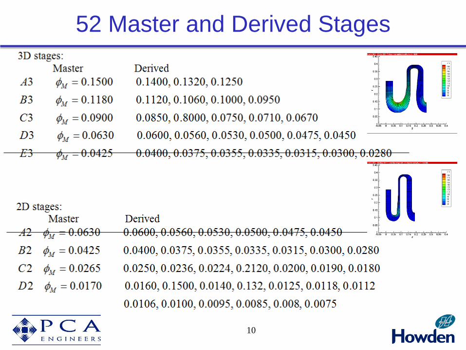
52 Master and Derived Stages
10

Outline
• Objectives
• Master and Derived Stages
• 1D Design Guidelines
• Detailed design
• Manufacture and Testing
• Summary
11

Impeller
12
• Impeller axial length increases in high
flow coefficient stages
• Previous guideline by Aungier
𝐿𝑖𝑚𝑝
𝑟2= 0.08 + 3.16𝜙
• Current guideline results in shorter high
flow coefficient stages
𝐿𝑖𝑚𝑝
𝑟2= 0.1 + 2𝜙
• Typically 0.6-0.7 for turbocharger and
gas turbine impellers (cf 0.4 from the
above equation)
2b
2r
outrcr _
icr
ihr
outrcb _
Limp

Impeller
13
• Impeller eye radius ratio
𝑟𝑖𝑐
𝑟2= 0.5 + 1.5𝜙
• Impeller hub radius ratio
𝑟𝑖ℎ
𝑟2= 0.35
• Impeller outlet width ratio
𝑏2
𝑟2= 0.05 + 0.8𝜙
• 10-20% pinch in the diffuser,
determined in the detailed design
2b
2r
outrcr _
icr
ihr
outrcb _
Limp

Diffuser
14
• Diffuser radius ratio of 1.6 to reduce the kinetic energy at inlet to the
crossover bend
• Vaneless diffusers at high and medium flow coefficients
• Wider operating range

Diffuser
15
• Vaned diffuser at low flow coefficient stages:
• High loss generation in excessively narrow diffuser passages
• larger impeller tip widths have been used to widen the passage
• Vaned diffusers have been used to avoid possible flow instabilities and
high losses associated with high flow angles in vaneless diffusers

Return Channel
16
2b
2r
outrcr _
icr
ihr
outrcb _
• Accelerating flow from deswirl outlet to the inlet of the downstream impeller
to avoid possible flow separations
• 𝒃𝒓𝒄_𝒐𝒖𝒕 depends on the flow coefficient of the downstream impeller (𝜙𝑛+1)
• 𝜙𝑛+1 depends on the density ratio and hence on the tip speed Mach
number (𝑀𝑢2) of the upstream stage
)1/(12
2
212
2
221
)1(1)/()/(4
n
u
nntttn
MuDm
fff
• A return channel designed for high 𝑀𝑢2 results
in excessive deceleration at low speed
• Return channel width is typically larger than
the diffuser width

Return Channel
17
2b
2r
outrcr _
icr
ihr
outrcb _
• From the guidelines presented before it can be
shown:
• 𝑅 =𝑟𝑟𝑐_𝑜𝑢𝑡
𝑟𝑖𝑐= 1.25 − 1.35
• Smooth bend at the inlet
• 𝐴0/𝐴𝑖 =1.25 to 1.35
• 25% to 35% acceleration upstream of the
impeller
2
)/()/(/
2
2
2
222_
rrrr
Rr
r
A
Arb ihic
ici
ooutrc

Outline
• Objectives
• Master and Derived Stages
• 1D Design Guidelines
• Detailed design
• Manufacture and Testing
• Summary
18
19
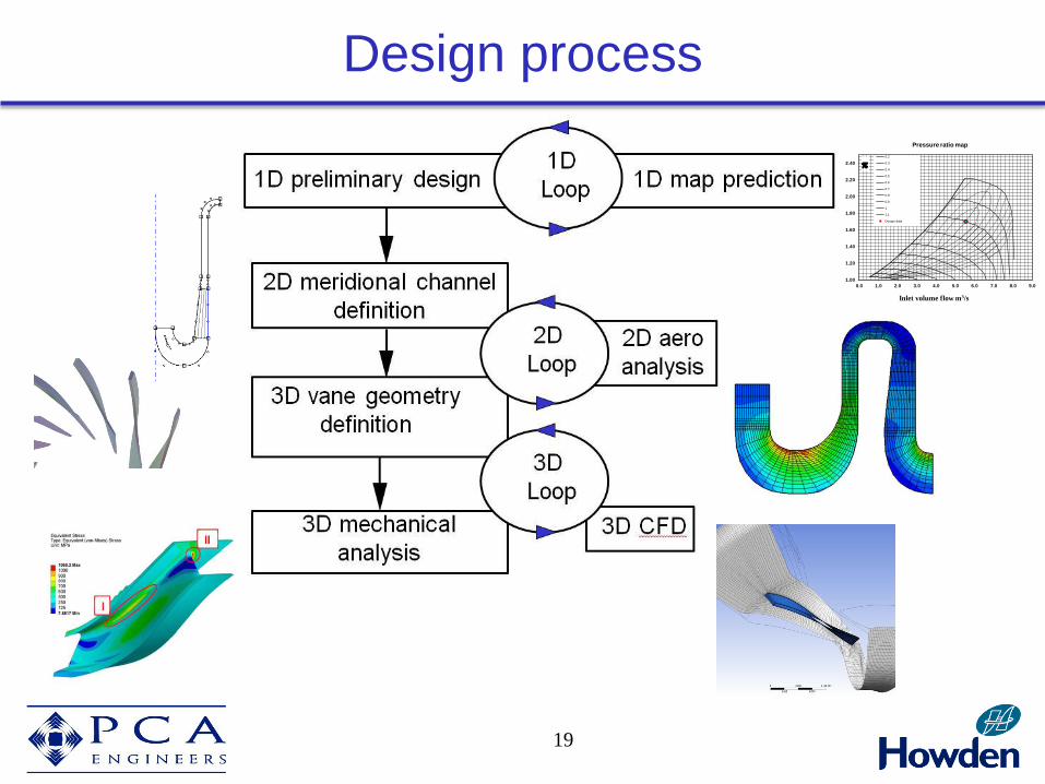
Design process
1.00
1.20
1.40
1.60
1.80
2.00
2.20
2.40
0.0 1.0 2.0 3.0 4.0 5.0 6.0 7.0 8.0 9.0
Inlet volume flow m3/s
Pressure ratio map
0.2
0.3
0.4
0.5
0.6
0.7
0.8
0.9
1
1.1
Design data

20
Parameterised geometry generation of flow channel
• 3D stages at high f
• 2D stages at lower f
z
r
ihr
icr
icl
shroudl
2r
or
ob
2b
hr1
cr1
ihl
le 1b
z
r
ihr
icr
icl
shroudl
2r
or
ob
2b
hr1cr1
ihl
shroud
le
1b

Parameterised geometry generation of flow channel
21
• Flow channel of full stage modelled with Bezier curves set up as patches
3
3
2
2
1
2
0
3 )1(3)1(3)1( PuPuuPuuPuR
3
patch corner
patch internal
• Vista GEO • Based on method of Casey (1983)
• Similar system system as used in ANSYS Bladegen
• Links to throughflow, mechanical analysis and to ANSYS bladegen
0 1
2
u 2r
1
2
3
4
5
6
1) Inlet bend
2) Impeller
3) Diffuser
4) Crossover bend
5) Return channel
6) Outlet

Geometry generation of blades
22
• Blades modelled with 24 free parameters,
amenable to automated optimisation
• Ruled surface defined by hub and casing
blade angles and thickness distributions
• Splitter leading edge position
• Ellipse parameters for rounding of edges
z
r
cs
hs
z
r
cs
hs
m
0c
0 1.0
0°
-90°
0.50
-30°
-60° 1c
2c3c 4c
0h
1h 2h3h
4h
m
0c
0 1.0
0°
-90°
0.50
-30°
-60° 1c
2c3c 4c
0h
1h 2h3h
4h
m
0c
0 1.00
1c 2c
3c
0h
1h
2h
3h
m
0c
0 1.00
1c 2c
3c
0h
1h
2h
3h
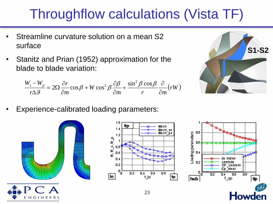
Throughflow calculations (Vista TF)
23
S1-S2
• Streamline curvature solution on a mean S2
surface
• Stanitz and Prian (1952) approximation for the
blade to blade variation:
• Experience-calibrated loading parameters:
rWmrm
Wm
r
r
WW ps
cossincoscos2
22

• 9-stage, real gas calculation (extent of our experience)
CFD analysis (ANSYS CFX)

CFD analysis (ANSYS CFX)
25
• Detailed optimisation is based on 3D CFD calculations:
• Single passage steady state calculations
• Structured grid in bladed passages using ANSYS Turbogrid (ATM)
• Effect of fillets and leakages can be ignored in the initial design loop
• Unstructured mesh for complex parts (larger mesh size)
Gas path only
Shroud leakage path
Impeller with fillets

CFD analysis (ANSYS CFX)
Commercial-in-Confidence
• Calculations using CFX 17.1 with SST turbulence model
• Mesh size typically 4m nodes (3.5m in impeller, diffuser and leakage paths)
• Compared to typically 250k nodes for a ‘design’ iteration (using k-e)

Efficiency as a function of flow coefft.
Commercial-in-Confidence
f = V/UD2
FM = 4V/UD2

Outline
• Objectives
• Master and Derived Stages
• 1D Design Guidelines
• Detailed design
• Manufacture and Testing
• Summary
28
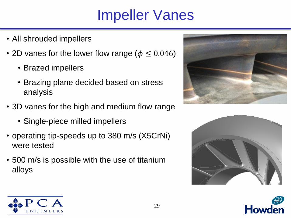
Impeller Vanes
29
• All shrouded impellers
• 2D vanes for the lower flow range (𝜙 ≤ 0.046)
• Brazed impellers
• Brazing plane decided based on stress
analysis
• 3D vanes for the high and medium flow range
• Single-piece milled impellers
• operating tip-speeds up to 380 m/s (X5CrNi)
were tested
• 500 m/s is possible with the use of titanium
alloys

Performance Testing
30
• Newly built, dedicated test facility at Howden ČKD Compressors
(DARINA)
• The master stages were tested along with their smallest trim or derived
stages at a range of tip speed Mach number from 0.3 to 1.1
• Detailed flow measurements were taken at five planes at impeller inlet,
impeller outlet, diffuser outlet, return-channel inlet and return-channel
outlet
• More than 120 pressure and 50
temperature probes were used
• Kiel probes, 3-hole probes and high
frequency pressure transducers

CFD analysis (ANSYS CFX)
31
• Fillets and leakages need to be included for accurate prediction of
performance
• Large effects of the leakage flow on efficiency at low flow coefficients

Outline
• Objectives
• Master and Derived Stages
• 1D Design Guidelines
• Detailed design
• Manufacture and Testing
• Summary
32

Summary
33
• The design of a new family of process compressor stages
using modern design methods has been described.
• The guidelines for preliminary design of the stages has been
presented and aspects of the detailed design discussed.
• The test results show that the performance objectives have
been achieved and the design tools have been effective
• Comparison of the CFD and test results confirm that the
inclusion of real geometry features is necessary to obtain
good agreement with the measured performance


![Procedure for Design and Development...2020/06/10 · Planning design and development stages and activities [job title] plans stages and controls for the design and development process,](https://static.fdocuments.in/doc/165x107/613dd6962809574f586e3788/procedure-for-design-and-development-20200610-planning-design-and-development.jpg)