The Clivet Enhanced Hydronic System - clivet-newsletter.it · Technical Focus The Clivet Enhanced...
36
Technical Focus The Clivet Enhanced Hydronic System Evolving central plant design to the best life-cycle saving Application for multi-level office building
Transcript of The Clivet Enhanced Hydronic System - clivet-newsletter.it · Technical Focus The Clivet Enhanced...

Technical Focus
The Clivet Enhanced Hydronic System Evolving central plant design to the best life-cycle saving Application for multi-level office building

TF14I001GB-02 Technical Focus · The Clivet Enhanced Hydronic System 2
The data contained in this document are not binding and may be modified by the manufacturer without notice. All reproduction, even partial, is prohibited. © Copyright - CLIVET S.p.A. - Feltre (BL) – Italy
Clivet S.p.A. believes that the information contained in this document is correct. However the application of this information, system choices and evaluation of design remain the responsibility of the reader. Clivet S.p.A does not assume any responsibility for any action or inaction taken as a result of this document nor for the misuse of the information in this document.
FOREWORD 3
THE CLIVEY ENHANCED HYDRONIC SYSTEM 3
TECHNOLOGIES AND BENEFITS 4
APPLICATION FOR MULTI-LEVEL OFFICE BUILDING 6
SYSTEM DESIGN 8
ENERGY ANALYSIS 10
CONCLUSIONS 31
APPENDIX 32
Effect of climate 13
Effect of cooling technology 27
Effect of heat recovery technology 25
Effect of heating technology 29
TABLE OF CONTENTS

TF14I001GB-02 3 Technical Focus · The Clivet Enhanced Hydronic System
FOREWORD
Keeping optimal comfort conditions within buildings can result in significant saving on capital and operating cost, able to affect the most accurate business plan.
This behaviour applies worldwide, in both new constructions and renovations; it is even enhanced in the commercial sector, due to the higher range of challenging constraints such as high space loads, simultaneous cooling and heating, outdoor air management and domestic hot water, if any.
Central plants are probably the most popular HVAC design in this sector: they can further benefit from many enhanced technologies and solutions, already available from the Industry but applied much less than they would, providing excellence in performance, easier design, energy saving and competitive overall cost year-round.
For these reasons, the Enhanced Hydronic System from Clivet is here introduced, looking at its applications and exploring the benefits over traditional equipment.
THE CLIVET ENHANCED HYDRONIC SYSTEM
Commercial buildings are specialised by function: shopping centres, offices, hotels and restaurants, entertainment, hospitals provide different services and have individual comfort requirements, affecting all together the overall energy efficiency.
The Clivet Enhanced Hydronic System is the standardized, industrial comfort solution able to fit to individual requirements thanks to its effective modular design.
Core of the System is ZEPHIR3, the complete packaged Primary Air supply System with thermodynamic energy recovery.
Primary air today is crucial: demanding Indoor Air Quality (IAQ) standards, virtually sealed building and reduced heat gain/loss through the envelope make this function the major load.
As very often this is higher than space loads, it easily becomes one of the largest operational costs at all.
ZEPHIR3 provides all Primary Air functions in a single stand-alone System: supply and exhaust air management with thermodynamic energy recovery, full outdoor air operation, total humidity and automatic temperature control through its in-built reverse cycle refrigeration circuit. It is:
cost effective, as it gets rid of all pipework to traditional Outdoor Air AHU’s (inclusive of pumps, valves, water tanks, controls) and at the same time reduce both size and cost of central cooling and heating stations (liquid chillers, boilers and relevant auxiliary equipment)
energy efficient, as extract air is the heat source: this results in twice as much efficiency as usual refrigeration circuit do. Furthermore, as an electric heat pump it does not use any fossil fuel, for superior environmental performance
effective on IAQ, due to electronic filters able to keep 99% pure air and relentless extract to eliminate indoor pollutants.
Its totally independent operation allows much more flexible system design, as never done before with central bespoke equipment.
Fig. 1: The Clivet Enhanced Hydronic System is the effective solution in most commercial applications, such as Office buildings, Shopping centres, Hotels and Hospitals.
Fig. 2: ZEPHIR3 encloses all functions for stand-alone operation. Every single unit is full factory tested, thus on-site commissioning is much shorter than usual.
PIPEWORK
CHILLED WATER HOT WATER
Office
Open
Space
MeetingRooms
TERMINAL UNITS

TF14I001GB-02 Technical Focus · The Clivet Enhanced Hydronic System 4
Fig. 3: The SPINChiller range pioneered the modular Scroll technology, providing at a time sustainable ESEER and compact size.
Chilled water and/or hot water for space loads and domestic hot water, if any, are provided by SPINCHILLER through the widest and more flexible range on the market:
sustainable, as its modular Scroll technology results in superior seasonal efficiency at the most competitive overall cost, more effective than other equipment even using VFD compressors
versatile, as the many functions available fit in any application and climate: chiller, freecooling chiller, heat pump, multifunction heat pump for 2-pipe, 4-pipe and DHW management. Different energy versions match with individual capital cost dynamics. Both air source and water source are available.
reliable, thanks to the in-built automatic functions such as Hydropack water circulation, free heat recovery, low / high ambient operation
ELFO Space fan coil units are an integral part of the System, fitting with both energy challenges and IAQ issues:
energy efficient, as DC brushless fan motors save 60% energy over traditional units
quiet, to keep optimal comfort on the acoustic side as well
flexible, being available in both cased and uncased versions, horizontal ductable and cassette with many options and accessories to virtually fit in any environment.
Fig. 4: ELFOSpace terminal units are available in both 2-pipe and 4-pipe versions, either cased or uncased.
Fig. 5. Features and benefits also apply with alternative local units, such as radiant panels, induction terminals and chilled beams.
TECHNOLOGIES AND BENEFITS
The Clivet Enhanced Hydronic System is based on drivers such as: Reverse cycle heat pump to exploit renewable energy The electric Heat Pump technology is promoted and supported by the European Union with specific standards, such as the EU Directive 2009/28/CE of April 23rd 2009 that recognises ambient air as a renewable source. Compared to a combustion system, the electric Heat Pump technology allows: Energy saving and reduction of the CO2 emission by an average of 50% Use of electric energy, more and more produced through alternative and renewable
sources Operation reliability and reduced maintenance No fossil combustion and therefore absence of chimney, absence of periodical
controls on the emissions in the ambient and no local production of fine dust Cost reduction of first investment with the reversible models that use a single system
for both heating and cooling.
Fig. 6: Electric heat pump is the distintive technology: it gets rid of fossil fuels and direct emission in the environment while saving 50% on primary energy.
CONVENTIONAL COMBUSTION
HEAT PUMPS
Primaryenergy102
Fossilfuels
Thermalenergy102
Primaryenergy54,2
Hydroel.
Thermal
Renewable
Electricenergy25
Renewableenergy75
Free energyfromambient
100
100HEATPUMP
Avg eff. = 98%
SCOP = 4
47% saving on Primary energy50% saving on CO2 emissions
ConversionFactor = 2,17
TF14I001GB-02 5 Technical Focus · The Clivet Enhanced Hydronic System
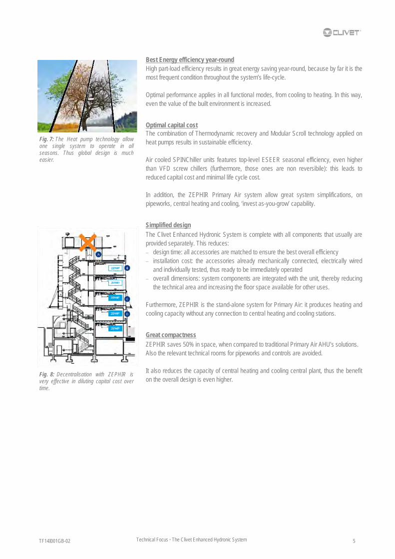
Best Energy efficiency year-round High part-load efficiency results in great energy saving year-round, because by far it is the most frequent condition throughout the system’s life-cycle. Optimal performance applies in all functional modes, from cooling to heating. In this way, even the value of the built environment is increased.
Optimal capital cost The combination of Thermodynamic recovery and Modular Scroll technology applied on heat pumps results in sustainable efficiency. Air cooled SPINChiller units features top-level ESEER seasonal efficiency, even higher than VFD screw chillers (furthermore, those ones are non reversibile): this leads to reduced capital cost and minimal life cycle cost. In addition, the ZEPHIR Primary Air system allow great system simplifications, on pipeworks, central heating and cooling, ‘invest as-you-grow’ capability.
Simplified design The Clivet Enhanced Hydronic System is complete with all components that usually are provided separately. This reduces: design time: all accessories are matched to ensure the best overall efficiency installation cost: the accessories already mechanically connected, electrically wired
and individually tested, thus ready to be immediately operated overall dimensions: system components are integrated with the unit, thereby reducing
the technical area and increasing the floor space available for other uses. Furthermore, ZEPHIR is the stand-alone system for Primary Air: it produces heating and cooling capacity without any connection to central heating and cooling stations.
Great compactness ZEPHIR saves 50% in space, when compared to traditional Primary Air AHU’s solutions. Also the relevant technical rooms for pipeworks and controls are avoided. It also reduces the capacity of central heating and cooling central plant, thus the benefit on the overall design is even higher.
Fig. 7: The Heat pump technology allow one single system to operate in all seasons. Thus global design is much easier.
Fig. 8: Decentralisation with ZEPHIR is very effective in diluting capital cost over time.

TF14I001GB-02 Technical Focus · The Clivet Enhanced Hydronic System 6
To assess the effect of the Clivet Enhanced Hydronic System on both capital and overall cost, a mid-size office building with glazed facades has been analysed in year-round operation in the city of London, United Kingdom.
This performance has been compared to a traditional HVAC system, based on outdoor air AHU’s with rotary heat recovery (120 Pa pressure drop per air stream), air cooled liquid chillers with Screw compressors, gas condensing boilers.
To get a complete overview, the energy analysis has then been further done on the same building in different conditions:
Climate: Rome, Italy; Valencia, Spain; Krakow, Poland; Moscow, Russian Federation
Heat recovery technology: Passive cross-flow heat exchanger
Cooling technology: Inverter Screw, Centrifugal Magnetic bearing
Heating technology: Air-to-water heat pump
Building details and relevant design data (night set back values within brackets) are:
APPLICATION FOR MULTI-LEVEL OFFICE BUILDING
Cenni di cambiamento, social housing Milano, Italy
Woolmore Primary School London, United Kingdom.
Primary air
Attendance (0,12 persons/m2) nr. 792
Airflow (11 l/s per person) m3/h 31.360
Summer design, indoors
Temperature °C 25 (28)
Relative humidity % 55 (65)
Supply air primary temperature °C 20 (OFF)
Supply air primary relative humidity g/kg 9,5 (OFF)
Winter design, outdoors
Temperature °C 20 (18)
Relative humidity % 40 (40)
Supply air primary temperature °C 22 (OFF)
Supply air primary relative humidity g/kg not controlled
Internal loads (standard operation time)
Lighting W/m2 5
Electrical equipment (computers, printers, etc.). W/m2 5
Air conditioned space
Application - Offices
Net floor m2 6.600
Height m 3
Standard (business hours) operation time - 8am to 8pm Monday to Friday
Night set back operation time - 9pm to 7am
Monday to Friday Holidays 24h and Saturday
Each floor is 2,200 m2 wide, suitable for multi-tenant location.
During the unoccupied mode, night setback is an effective energy saving strategy.
TF14I001GB-02 7 Technical Focus · The Clivet Enhanced Hydronic System
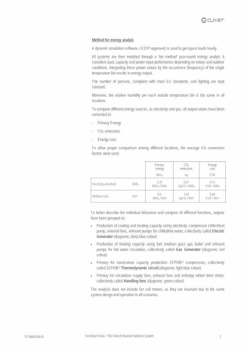
Method for energy analyis
A dynamic simulation software, LEED® approved, is used to get space loads hourly.
All systems are then modeled through a ‘bin method’ year-round energy analyis: it considers load, capacity and power input performance depending on indoor and outdoor conditions. Integrating those power values by the occurrence (frequency) of the single temperature bin results in energy output.
The number of persons, compliant with most EU standards, and lighting are kept constant.
Moreover, the relative humidity per each outside temperature bin is the same in all locations.
To compare different energy sources, as electricity and gas, all output values have been converted to:
Primary Energy
CO2 emissions
Energy cost.
To allow proper comparison among different locations, the average EU conversion factors were used.
Primary energy
CO2
emissions Energy
cost
Electricity adsorbed 2,18
kWhp / kWhe 0,61
kgCO2 / kWhe 0,15
EUR / kWhe
Methane Gas 9,6
kWhp / Nm3 1,84
kgCO2 / Nm3 0,80
EUR / Nm3
kWhp kg EUR
kWhe
Nm3
To better describe the individual behaviour and compare all different functions, outputs have been grouped as:
Production of cooling and heating capacity using electricity: compressor chiller/heat pump, external fans, relevant pumps for chilled/hot water, collectively called Electric Generator (diagrams: deep blue colour)
Production of heating capacity using fuel (methan gas): gas boiler and relevant pumps for hot water circulation, collectively called Gas Generator (diagrams: red colour)
Primary Air stand-alone capacity production: ZEPHIR3 compressors, collectively called ZEPHIR3 Thermodynamic circuit (diagrams: light blue colour)
Primary Air circulation: supply fans, exhaust fans and enthalpy wheel drive motor, collectively called Handling fans (diagrams: green colour)
The analysis does not include fan coil motors, as they are invariant due to the same system design and operation in all scenarios.

TF14I001GB-02 Technical Focus · The Clivet Enhanced Hydronic System 8
Both the Clivet Enhanced Hydronic System and the traditional HVAC system provide Primary Air management and space air conditioning through local terminal units, fancoil type.
Individual sizing and configuration depend on ambient conditions and relevant building load profile.
CLIVET ENHANCED HYDRONIC SYSTEM
ZEPHIR systems provide local stand-alone Primary Air management and energy recovery: they are all located in technical rooms close to the space. They feature constant supply temperature control and include supply and return fan sections, double air filtration (G4 and electronic H10), summer dehumidification with reheating via hot gas recovery, constant airflow control. Electrical panel and automatic controls are in-built.
Central hot water or chilled water is supplied by SPINChiller air-to-water heat pump, to feed as many as 200 two-pipe fancoil units.
As the System is fully electric, no gas piping, relevant safety equipment and chimneys are needed.
SYSTEM DESIGN
ELFOSPACE
SPINCHILLER CHILLED / HOT WATER
ZEPHIR

TF14I001GB-02 9 Technical Focus · The Clivet Enhanced Hydronic System
TRADITIONAL HVAC SYSTEM
Primary air is provided by bespoke Air Handling Units (AHU) also located in technical rooms close to the space. Each AHU feature constant supply temperature control and include supply and return fan sections as well. Passive heat recovery is achieved through enthalpy wheel. Double air filtration is based on G4 and F7 bag filters. A ‘double function’ water coil provides either heating or cooling capacity. Summer dehumidification with reheating via hot water and constant airflow control are also included. As part of the on-site installation, units are completed with electrical panel and individual automatic controls. Global design includes suitable utility tunnels and corridors for all water pipework.
Central hot water is provided by gas fired condensing boilers, complete with gas piping and control, safety equipment, chimney on-site assembly.
Chilled water is supplied by air-cooled liquid chillers with screw compressors, shell and tube evaporators, aluminium finned condenser coils, axial fans.
Seasonal changeover, from chilled to hot water circulation and back, is provided by individual shut-off valves.
Both boilers and chillers result in larger capacity than Clivet Enhanced Hydronic System, as they must feed all Primary Air Handling Units and 200 two-pipe fancoils at a time.
TERMINAL UNITS
HOT WATER
PIPEWORK BOILER CHILLER
CHILLED WATER
AHU
CONTROLS
TF14I001GB-02 Technical Focus · The Clivet Enhanced Hydronic System 10
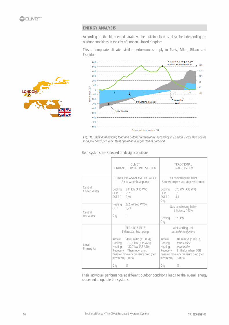
According to the bin-method strategy, the building load is described depending on outdoor conditions in the city of London, United Kingdom.
This a temperate climate: similar performances apply to Paris, Milan, Bilbao and Frankfurt.
Fig. 11: Individual building load and outdoor temperature occurency in London. Peak load occurs for a few hours per year. Most operation is requested at part load.
ENERGY ANALYSIS
CLIVET ENHANCED HYDRONIC SYSTEM
TRADITIONAL HVAC SYSTEM
Central Chilled Water
SPINchiller3 WSAN-XSC3 90.4 EXC Air-to-water heat pump
Cooling 244 kW (A35 W7) EER 2,78 ESEER 3,94 Heating 282 kW (A7 W45) COP 3,23 Q.ty 1
Air cooled liquid Chiller Screw compressor, stepless control
Cooling 370 kW (A35 W7) EER 3,1 ESEER 4,1 Q.ty 1
Central Hot Water
Gas condensing boiler Efficiency 102%
Heating 320 kW Q.ty 1
Local Primary Air
ZEPHIR3 SIZE 3 Exhaust air heat pump
Airflow 4000 m3/h (1100 l/s) Cooling 19,1 kW (A35 A25) Heating 20,7 kW (A7 A20) Recovery Thermodynamic Passive recovery pressure drop (per air stream) 0 Pa Q.ty 8
Air Handling Unit bespoke equipment
Airflow 4000 m3/h (1100 l/s) Cooling from chiller Heating from boiler Recovery Enthalpy wheel 70% Passive recovery pressure drop (per air stream) 120 Pa Q.ty 8
Both systems are selected on design conditions.
Their individual performance at different outdoor conditions leads to the overall energy requested to operate the systems.

TF14I001GB-02 11 Technical Focus · The Clivet Enhanced Hydronic System
Traditional HVAC system
Clivet Enhanced Hydronic System
Fig. 12: Further to the great energy saving to operate handling fans, the Clivet Enhanced Hydronic System benefits from the Heat Pump technology to considerably reduce also the primary energy to generate both cooling and heating capacity. This results in lower CO2 emissions as well.
LONDON: Primary Energy Consumption and CO2 Emissions
0
2000
4000
6000
8000
10000
0
5000
10000
15000
20000
25000
30000
35000
40000
45000
-4 -2 0 2 4 6 8 10 12 14 16 18 20 22 24 26 28
Total CO2 emissions
Handling fans
ZEPHIR3 Thermodynamic Circuit
Gas generator
Electric Generator
Outdoor temperature [°C]
Primary Energy [kWh] CO2 emissions [kg]
0
2000
4000
6000
8000
10000
0
5000
10000
15000
20000
25000
30000
35000
40000
45000
-4 -2 0 2 4 6 8 10 12 14 16 18 20 22 24 26 28
Total CO2 emissions
Outdoor temperature [°C]
CO2 emissions [kg] Primary Energy [kWh]
Fig. 13: Compared to the traditional HVAC system (2), ZEPHIR (1) allows 51% saving on energy to operate fans.
Handling fans for Primary Air
Fig. 15: Compared to the traditional HVAC system (2), ZEPHIR3 (1) provides hot gas reheat for free and further increases the refrigeration circuit efficiency by 35%.
Reheat for Primary Air
0
3000
6000
9000
-4 -2 0 2 4 6 8 10 12 14 16 18 20 22 24 26 28
Primary Energy [kWh]
Outdoor temperature [°C]
Fig. 14: Being totally stand-alone, ZEPHIR (1) requires no energy to circulate hot water and chilled water for Primary Air, as it would happen on the traditional HVAC system (2).
Water pumps for Primary Air
0
250
500
750
1000
1250
1500
-4 -2 0 2 4 6 8 10 12 14 16 18 20 22 24 26 28
Outdoor temperature [°C]
2
0
100
200
300
400
500
600
-4 -2 0 2 4 6 8 10 12 14 16 18 20 22 24 26 28
1
Outdoor temperature [°C]
Primary Energy [kWh]
Primary Energy [kWh]
2
1
2
1
Chiller
ZEPHIR3
(reheat off)
ZEPHIR3
(reheat on)
4,2
6,9
EER 25°C
9,3

TF14I001GB-02 Technical Focus · The Clivet Enhanced Hydronic System 12
Fig. 16: The Clivet Enhanced Hydronic System reduces at a time the carbon footprint of the building and the running cost to keep year-round the requested comfort conditions.
127.78863.198
179.508
111.947
279.110
212.578
0
100.000
200.000
300.000
400.000
500.000
600.000
TOTAL PRIMARY ENERGY [kWh]
Traditional HVAC system
8.7934.348
12.351
7.703
23.146
14.627
0
5.000
10.000
15.000
20.000
25.000
30.000
35.000
40.000
45.000
50.000
ENERGY COST [EUR]
LONDON: OVERALL CONSUMPTION
Gas Generator
ZEPHIR3 Thermodynamic Circuit
Electric Generator
Handling fans
CLIVET Enhanced Hydronic System
586.406 -34%
387.723
35.75717.684
50.229
31.325
54.185
59.483
0
20.000
40.000
60.000
80.000
100.000
120.000
140.000
160.000
TOTAL CO2 EMISSIONS [kg]
140.171
108.492
Traditional HVAC system
CLIVET Enhanced Hydronic System
44.290
26.678
Traditional HVAC system
CLIVETEnhanced Hydronic System
-23%
-40%

TF14I001GB-02 13 Technical Focus · The Clivet Enhanced Hydronic System
ROME
Fig. 17: Individual building load and outdoor temperature occurency in Rome.
EFFECT OF CLIMATE
This is a mediterranean climate: similar performances apply to Barcelona, Lisbon and Palermo.
Changing the location of the building results in new load profile. Therefore, both Systems have to be selected on different design conditions.
All remaining functions, technology and performance are unchanged.
Output figures confirm the benefits from the Clivet Enhanced Hydronic System.
CLIVET ENHANCED HYDRONIC SYSTEM
TRADITIONAL HVAC SYSTEM
Central Chilled Water
SPINchiller3 WSAN-XSC3 140.4 EXC Air-to-water heat pump
Cooling 371 kW (A35 W7) EER 2,74 ESEER 3,97 Heating 424 kW (A7 W45) COP 3,30 Q.ty 1
Air cooled liquid Chiller Screw compressor, stepless control
Cooling 530 kW (A35 W7) EER 3,2 ESEER 4,1 Q.ty 1
Central Hot Water
Gas condensing boiler Efficiency 102%
Heating 200 kW Q.ty 1
Local Primary Air
ZEPHIR3 SIZE 3 Exhaust air heat pump
Airflow 4000 m3/h (1100 l/s) Cooling 19,1 kW (A35 A25) Heating 20,7 kW (A7 A20) Recovery Thermodynamic Passive recovery pressure drop (per air stream) 0 Pa Q.ty 8
Air Handling Unit bespoke equipment
Airflow 4000 m3/h (1100 l/s) Cooling from chiller Heating from boiler Recovery Enthalpy wheel 70% Passive recovery pressure drop (per air stream) 120 Pa Q.ty 8
Both systems are selected on design conditions.

TF14I001GB-02 Technical Focus · The Clivet Enhanced Hydronic System 14
Fig. 18: In mediterranean locations, most energy is requested in cooling operation. Also in this scenario, the Clivet Enhanced Hydronic System benefits from the superior thermodynamic efficiency of its components and the saving on handling fans for Primary Air.
Traditional HVAC system
Clivet Enhanced Hydronic System
ROME: Primary Energy Consumption and CO2 Emissions
Handling fans
ZEPHIR3 Thermodynamic Circuit
Gas generator
Electric Generator
0
3.000
6.000
9.000
12.000
15.000
18.000
21.000
0
10000
20000
30000
40000
50000
60000
70000
80000
-4 -2 0 2 4 6 8 10 12 14 16 18 20 22 24 26 28 30 32
Total CO2 emissions
Outdoor temperature [°C]
Primary Energy [kWh] CO2 emissions [kg]
0
3.000
6.000
9.000
12.000
15.000
18.000
21.000
0
10000
20000
30000
40000
50000
60000
70000
80000
-4 -2 0 2 4 6 8 10 12 14 16 18 20 22 24 26 28 30 32
Total CO2 emissions
Outdoor temperature [°C]
CO2 emissions [kg] Primary Energy [kWh]
TF14I001GB-02 15 Technical Focus · The Clivet Enhanced Hydronic System
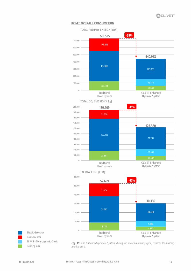
127.19463.030
429.918
92.770
171.413
285.133
0
100.000
200.000
300.000
400.000
500.000
600.000
700.000
TOTAL PRIMARY ENERGY [kWh]
Fig. 19: The Enhanced hydronic System, during the annual operating cycle, reduces the building running costs.
35.59117.637
120.298
25.958
33.220
79.785
0
20.000
40.000
60.000
80.000
100.000
120.000
140.000
160.000
180.000
200.000
TOTAL CO2 EMISSIONS [kg]
Traditional HVAC system
8.7754.337
29.582
6.383
14.342
19.619
0
10.000
20.000
30.000
40.000
50.000
60.000
ENERGY COST [EUR]
ROME: OVERALL CONSUMPTION
CLIVET Enhanced Hydronic System
728.525 -39%
440.933
189.109
123.380
Traditional HVAC system
CLIVET Enhanced Hydronic System
52.699
30.339
Traditional HVAC system
CLIVET Enhanced Hydronic System
-35%
-42%
Gas Generator
ZEPHIR3 Thermodynamic Circuit
Electric Generator
Handling fans

TF14I001GB-02 Technical Focus · The Clivet Enhanced Hydronic System 16
VALENCIA
Fig. 20: Individual building load and outdoor temperature occurency in Valencia.
This is a hot climate: similar performances apply to Athens and Bangalore.
Both systems are selected on design conditions.
CLIVET ENHANCED HYDRONIC SYSTEM
TRADITIONAL HVAC SYSTEM
Central Chilled Water
SPINchiller3 WSAN-XSC3 160.4 EXC Air-to-water heat pump
Cooling 417 kW (A35 W7) EER 2,78 ESEER 4,09 Heating 469 kW (A7 W45) COP 3,28 Q.ty 1
Air cooled liquid Chiller Screw compressor, stepless control
Cooling 560 kW (A35 W7) EER 3,1 ESEER 4,0 Q.ty 1
Central Hot Water
Gas condensing boiler Efficiency 102%
Heating 130 kW Q.ty 1
Local Primary Air
ZEPHIR3 SIZE 3 Exhaust air heat pump
Airflow 4000 m3/h (1100 l/s) Cooling 19,1 kW (A35 A25) Heating 20,7 kW (A7 A20) Recovery Thermodynamic Passive recovery pressure drop (per air stream) 0 Pa Q.ty 8
Air Handling Unit bespoke equipment
Airflow 4000 m3/h (1100 l/s) Cooling from chiller Heating from boiler Recovery Enthalpy wheel 70% Passive recovery pressure drop (per air stream) 120 Pa Q.ty 8

TF14I001GB-02 17 Technical Focus · The Clivet Enhanced Hydronic System
Fig. 21: The primary energy required and the CO2 total emissions of Enhanced hydronic System for the air conditioning of the building are much lower than the traditional solution with screw stepless compressor.
Traditional HVAC system
Clivet Enhanced Hydronic System
VALENCIA: Primary Energy Consumption and CO2 Emissions
Handling fans
ZEPHIR3 Thermodynamic Circuit
Gas generator
Electric Generator
0
3.000
6.000
9.000
12.000
15.000
18.000
0
10000
20000
30000
40000
50000
60000
70000
-2 0 2 4 6 8 10 12 14 16 18 20 22 24 26 28 30 32 34
Total CO2 emissions
Outdoor temperature [°C]
Primary Energy [kWh] CO2 emissions [kg]
0
3.000
6.000
9.000
12.000
15.000
18.000
0
10000
20000
30000
40000
50000
60000
70000
-2 0 2 4 6 8 10 12 14 16 18 20 22 24 26 28 30 32 34
Total CO2 emissions
Outdoor temperature [°C]
CO2 emissions [kg] Primary Energy [kWh]

TF14I001GB-02 Technical Focus · The Clivet Enhanced Hydronic System 18
Fig. 22: The Enhanced hydronic System, during the annual operating cycle, reduces the building’s running costs.
Gas Generator
ZEPHIR3 Thermodynamic Circuit
Electric Generator
Handling fans
VALENCIA: OVERALL CONSUMPTION
TOTAL PRIMARY ENERGY [kWh]
127.44563.198
622.938
83.048
139.512
437.390
0
100.000
200.000
300.000
400.000
500.000
600.000
700.000
800.000
900.000
Traditional HVAC system
ENERGY COST [EUR]
CLIVET Enhanced Hydronic System
889.895 -34%
583.636
35.66117.684
174.308
23.238
27.034
122.389
0
50.000
100.000
150.000
200.000
250.000
TOTAL CO2 EMISSIONS [kg]
237.003
163.311
Traditional HVAC system
CLIVET Enhanced Hydronic System
8.7694.348
42.863
5.714
11.578
30.096
0
10.000
20.000
30.000
40.000
50.000
60.000
70.000
63.210
40.158
Traditional HVAC system
CLIVETEnhanced Hydronic System
-31%
-36%

TF14I001GB-02 19 Technical Focus · The Clivet Enhanced Hydronic System
KRAKOW
Fig. 23: Individual building load and outdoor temperature occurency in Krakow.
This is a cold climate: similar performances apply to Munich, Wien, Warsaw, Stockholm.
In this location, the Clivet Enhanced Hydronic System is complete with:
Option “Hydronic recovery device for extended operating range” on ZEPHIR3 down to –20°C ambient
Gas condensing boilers to operate below –6°C ambient.
As far as the traditional HVAC system is concerned, larger coils on AHU results in additional 30 Pa internal pressure drop.
Fig. 24: The ‘Hydronic recovery device for extended operating range’ on ZEPHIR3 is suitable for application in cold climate and in hot humid climate. It is a compact device within the System, thus keeping unchanged the unit dimensions and consequently its compactness.
Both systems are selected on design conditions.
CLIVET ENHANCED HYDRONIC SYSTEM
TRADITIONAL HVAC SYSTEM
Central Chilled Water
SPINchiller3 WSAN-XSC3 120.4 EXC Air-to-water heat pump
Cooling 323 kW (A35 W7) EER 2,74 ESEER 3,99 Heating 376 kW (A7 W45) COP 3,31 Q.ty 1
Gas condensing boiler Efficiency 102%
Heating 280 kW Q.ty 1
Air cooled liquid Chiller Screw compressor, stepless control
Cooling 480 kW (A35 W7) EER 3,2 ESEER 4,0 Q.ty 1
Central Hot Water
Gas condensing boiler Efficiency 102%
Heating 500 kW Q.ty 1
Local Primary Air
ZEPHIR3 SIZE 3 Exhaust air heat pump
Airflow 4000 m3/h (1100 l/s) Cooling 19,1 kW (A35 A25) Heating 20,7 kW (A7 A20) Recovery Thermodynamic Passive recovery pressure drop (per air stream) 0 Pa Q.ty 8
Air Handling Unit bespoke equipment
Airflow 4000 m3/h (1100 l/s) Cooling from chiller Heating from boiler Recovery Enthalpy wheel 70% Passive recovery pressure drop (per air stream) 120 Pa Q.ty 8
TF14I001GB-02 Technical Focus · The Clivet Enhanced Hydronic System 20
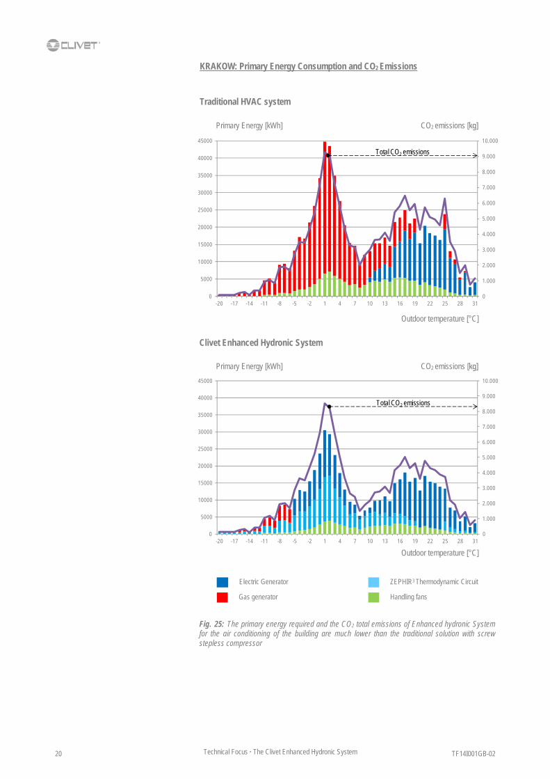
Fig. 25: The primary energy required and the CO2 total emissions of Enhanced hydronic System for the air conditioning of the building are much lower than the traditional solution with screw stepless compressor
Traditional HVAC system
Clivet Enhanced Hydronic System
KRAKOW: Primary Energy Consumption and CO2 Emissions
Handling fans
ZEPHIR3 Thermodynamic Circuit
Gas generator
Electric Generator
0
1.000
2.000
3.000
4.000
5.000
6.000
7.000
8.000
9.000
10.000
0
5000
10000
15000
20000
25000
30000
35000
40000
45000
-20 -17 -14 -11 -8 -5 -2 1 4 7 10 13 16 19 22 25 28 31
Total CO2 emissions
Outdoor temperature [°C]
Primary Energy [kWh] CO2 emissions [kg]
0
1.000
2.000
3.000
4.000
5.000
6.000
7.000
8.000
9.000
10.000
0
5000
10000
15000
20000
25000
30000
35000
40000
45000
-20 -17 -14 -11 -8 -5 -2 1 4 7 10 13 16 19 22 25 28 31
Total CO2 emissions
Outdoor temperature [°C]
CO2 emissions [kg] Primary Energy [kWh]

TF14I001GB-02 21 Technical Focus · The Clivet Enhanced Hydronic System
Fig. 26: The Enhanced hydronic System, during the annual operating cycle, reduces the building’s running costs.
131.34572.666
201.161
159.826
412.114
272.496
24.446
0
100.000
200.000
300.000
400.000
500.000
600.000
700.000
800.000
TOTAL PRIMARY ENERGY [kWh]
Traditional HVAC system
9.0375.000
13.841
10.997
34.163
18.750
2.032
0
10.000
20.000
30.000
40.000
50.000
60.000
36.75220.333
56.288
44.722
80.082
76.249
4.715
0
20.000
40.000
60.000
80.000
100.000
120.000
140.000
160.000
180.000
200.000TOTAL CO2 EMISSIONS [kg]
ENERGY COST [EUR]
KRAKOW: OVERALL CONSUMPTION
CLIVET Enhanced Hydronic System
744.620 -29%
529.434
173.122
146.019
Traditional HVAC system
CLIVET Enhanced Hydronic System
57.041
36.779
Traditional HVAC system
CLIVET Enhanced Hydronic System
-16%
-36%
Gas Generator
ZEPHIR3 Thermodynamic Circuit
Electric Generator
Handling fans

TF14I001GB-02 Technical Focus · The Clivet Enhanced Hydronic System 22
MOSCOW
Fig. 27: Individual building load and outdoor temperature occurency in Moscow.
This is a very cold climate.
In this location, the Clivet Enhanced Hydronic System is complete with:
Option “Extrapower-H (with additional hot water exchanger, without electronic filters)” on ZEPHIR3 down to –40°C ambient
Gas condensing boilers to operate below –6°C ambient.
As far as the traditional HVAC system is concerned, larger coils on AHU results in additional 60 Pa internal pressure drop.
Fig. 28: The ‘EXTRAPOWER-H (with additional hot water exchanger, without electronic filters)’ option on ZEPHIR3 is suitable for indoor application in very cold climate. For most operating time, ZEPHIR3 is independent from central hot water.
Both systems are selected on design conditions.
CLIVET ENHANCED HYDRONIC SYSTEM
TRADITIONAL HVAC SYSTEM
Central Chilled Water
SPINchiller3 WSAN-XSC3 140.4 EXC Air-to-water heat pump
Cooling 371 kW (A35 W7) EER 2,74 ESEER 3,97 Heating 424 kW (A7 W45) COP 3,30 Q.ty 1
Gas condensing boiler Efficiency 102%
Heating 560 kW Q.ty 1
Air cooled liquid Chiller Screw compressor, stepless control
Cooling 480 kW (A35 W7) EER 3,2 ESEER 4,0 Q.ty 1
Central Hot Water
Gas condensing boiler Efficiency 102%
Heating 600 kW Q.ty 1
Local Primary Air
ZEPHIR3 SIZE 3 Exhaust air heat pump
Airflow 4000 m3/h (1100 l/s) Cooling 19,1 kW (A35 A25) Heating 20,7 kW (A7 A20) Recovery Thermodynamic Passive recovery pressure drop (per air stream) 0 Pa Q.ty 8
Air Handling Unit bespoke equipment
Airflow 4000 m3/h (1100 l/s) Cooling from chiller Heating from boiler Recovery Enthalpy wheel 70% Passive recovery pressure drop (per air stream) 120 Pa Q.ty 8

TF14I001GB-02 23 Technical Focus · The Clivet Enhanced Hydronic System
The energy input to operate the EXTRAPOWER-H option is reported individually: it includes gas boiler consumption and pumping for hot water, collectively called EXTRAPOWER-H (diagrams: colour pink).
Fig. 29: The primary energy required and the CO2 total emissions of Enhanced hydronic System for the air conditioning of the building are much lower than the traditional solution with screw stepless compressor EXTRAPOWER-H uses only 15% of total primary energy of Enhanced Hydronic System. EXTRAPOWER-H produces only 11% of total CO2 dell'emissioni of Enhanced Hydronic System
EXTRAPOWER-H
Traditional HVAC system
Clivet Enhanced Hydronic System
Handling fans
ZEPHIR3 Thermodynamic Circuit
Gas generator
Electric Generator
Outdoor temperature [°C]
0
1.000
2.000
3.000
4.000
5.000
6.000
7.000
8.000
0
5000
10000
15000
20000
25000
30000
35000
40000
-25 -22 -19 -16 -13 -10 -7 -4 -1 2 5 8 11 14 17 20 23 26 29
Total CO2 emissions
Primary Energy [kWh] CO2 emissions [kg]
0
1.000
2.000
3.000
4.000
5.000
6.000
7.000
8.000
0
5000
10000
15000
20000
25000
30000
35000
40000
-25 -22 -19 -16 -13 -10 -7 -4 -1 2 5 8 11 14 17 20 23 26 29
Total CO2 emissions
Outdoor temperature [°C]
CO2 emissions [kg] Primary Energy [kWh]
MOSCOW: Primary Energy Consumption and CO2 Emissions

TF14I001GB-02 Technical Focus · The Clivet Enhanced Hydronic System 24
Fig. 30: The Enhanced hydronic System, during the annual operating cycle, reduces the building’s running costs. EXTRAPOWER-H
Gas Generator
ZEPHIR3 Thermodynamic Circuit
Electric Generator
Handling fans
MOSCOW: OVERALL CONSUMPTION
TOTAL PRIMARY ENERGY [kWh]
9.2944.532
14.478
11.962
46.514
17.450
8.935
10.362
0
10.000
20.000
30.000
40.000
50.000
60.000
70.000
37.79618.429
58.879
48.645
109.094
70.964
19.493
24.037
0
50.000
100.000
150.000
200.000
135.07465.861
210.419
173.846
561.192
253.610
107.225
124.640
0
100.000
200.000
300.000
400.000
500.000
600.000
700.000
800.000
900.000
Traditional HVAC system
ENERGY COST [EUR]
CLIVET Enhanced Hydronic System
906.685 -20%
725.182
TOTAL CO2 EMISSIONS [kg]
205.769
181.568
Traditional HVAC system
CLIVET Enhanced Hydronic System
70.286
53.241
Traditional HVAC system
CLIVETEnhanced Hydronic System
-12%
-24%

TF14I001GB-02 25 Technical Focus · The Clivet Enhanced Hydronic System
The case study in London can be now updated to check how much the recovery technology in the traditional HVAC system affects the year round energy performance. For this purpose, within the traditional HVAC system, the Air Handling Unit for Primary Air is now equipped with a standard sized cross-flow recovery, in lieu of the enthalpy wheel.
TOTAL PRIMARY ENERGY [kWh]
Fig. 33 When the traditional HVAC system features cross-flow recovery in lieu of enthalpy wheel recovery, the case study in London shows further benefit for the Clivet Enhanced Hydronic System. (W/ … = ‘Traditional HVAC system with’ …)
EFFECT OF HEAT RECOVERY TECHNOLOGY
Cross-flow 65% efficiency
Enthalpy wheel 70% efficiency
Thermodynamic recovery
Passive recovery pressure drop outdoor / exhaust [Pa]
200 / 200 120 / 120 0 / 0
Supply / Exhaust Fan power input [kW]
1,7 / 0,7 1,5 / 0,6 0,6 / 0,4
LONDON: OVERALL CONSUMPTION
Gas Generator
ZEPHIR3 Thermodynamic Circuit
Electric Generator
Handling fans
142.017 127.78863.198
179.547 179.508
111.947
307.945279.110
212.578
0
100.000
200.000
300.000
400.000
500.000
600.000
700.000
CLIVET Enhanced Hydronic System
W/ Enthalpy wheel recovery
W/ Cross-flow recovery
-38%
387.723
586.406 629.509
Fig. 31 Most enthalpy wheels feature also latent exchange. The thick rotor matrix results in higher pressure drops and frequent cross contamination.
Fig. 32 Most cross flow heat exchangers feature only sensible recovery and further fan power input increase due to higher pressure drop on air streams.
The traditional HVAC system results in: Higher energy for cooling and heating production, due to lower recovery Higher energy for ventilation, due to higher pressure drop.
-34%

TF14I001GB-02 Technical Focus · The Clivet Enhanced Hydronic System 26
TOTAL CO2 EMISSIONS [kg]
9.772 8.7934.348
12.354 12.351
7.703
25.53823.146
14.627
0
5.000
10.000
15.000
20.000
25.000
30.000
35.000
40.000
45.000
50.000
55.000
ENERGY COST [€]
Fig. 35: ZEPHIR3 allows further cost saving: 44% and 40% using respectively a cross-flow recovery in traditional solution in lieu of enthalpy wheel.
Fig. 34: ZEPHIR3 allows further reduction of CO2 emissions: 28% and 23% using respectively a cross-flow recovery in traditional solution in lieu of enthalpy wheel.
39.739 35.75717.684
50.240 50.229
31.325
59.77454.185
59.483
0
20.000
40.000
60.000
80.000
100.000
120.000
140.000
160.000
180.000
CLIVET Enhanced Hydronic System
W/ Enthalpy wheel recovery
W/ Cross-flow recovery
108.491
140.167 149.753 -28%
-44%
-23%
Gas Generator
ZEPHIR3 Thermodynamic Circuit
Electric Generator
Handling fans
CLIVET Enhanced Hydronic System
W/ Enthalpy wheel recovery
W/ Cross-flow recovery
26.678
44.290 47.664
-40%

TF14I001GB-02 27 Technical Focus · The Clivet Enhanced Hydronic System
EFFECT OF COOLING TECHNOLOGY
Liquid chiller Screw
Stepless
Liquid chiller Multi Scroll
Liquid chiller Screw
Inverter
Liquid chiller Centrifugal Magnetic Bearing
EER (A35 W7) 3,1 3,1 2,9 3,3
ESEER 4,1 4,7 4,8 5,0
Chiller Capital cost reference -10% +15% +70%
Keeping the application in London as case study, it is now possible to check how much the cooling technology affects the overall performance. For this purpose, different air cooled chillers are used: they feature the most popular compressor combinations to date. To get a complete overview, the gap on their capital cost is reported as well, keeping the Screw stepless type as reference.
63.198127.788 127.788 127.788 127.788
111.947
160.539 179.508 168.902 155.919
212.578
279.091279.110 279.091 279.091
0
100.000
200.000
300.000
400.000
500.000
600.000
W/ Screw Stepless
W/ Screw Inverter
W/ Centrifugal Magnetic bearing
W/ Multi Scroll
CLIVET Enhanced Hydronic System
387.723
567.418 586.406 575.781 562.798
LONDON: OVERALL CONSUMPTION
Fig. 36: The Clivet Enhanced Hydronic System features 32% average saving on primary energy over traditional systems, regardless the cooling technology.
TOTAL PRIMARY ENERGY [kWh]
The Clivet Enhanced Hydronic System features the SPINChiller water-to-air reverse cycle heat pump to produce either cooling or heating capacity year round. Due to this double function, the cooling efficiency of other liquid chillers looks higher, but it results in a negligible benefit on the year round overall energy performance, as reported, despite their capital cost jumping even up to +70% over the reference Screw stepless type. Important! At the same nominal cooling capacity, the capital cost of SPINChiller heat pump and the reference Screw stepless type would be equivalent. As ZEPHIR is independent from the central cooling and heating stations, the Clivet Enhanced Hydronic System reduces by over 30% the SPINChiller size, thus its capital cost as well.

TF14I001GB-02 Technical Focus · The Clivet Enhanced Hydronic System 28
Fig. 38: The Clivet Enhanced Hydronic System features 39% average saving on energy cost over traditional systems, regardless the cooling technology.
17.68435.757 35.757 35.757 35.757
31.325
44.922 50.229 47.261 43.629
59.483
54.18054.185 54.180 54.180
0
20.000
40.000
60.000
80.000
100.000
120.000
140.000
160.000
W/ Screw Stepless
W/ Screw Inverter
4.3488.793 8.793 8.793 8.793
7.703
11.046 12.351 11.622 10.728
14.627
23.14423.146 23.144 23.144
0
5.000
10.000
15.000
20.000
25.000
30.000
35.000
40.000
45.000
50.000
W/ Multi Scroll
CLIVET Enhanced Hydronic System
108.492
134.859 140.171 137.198 133.566
Fig. 37: The Clivet Enhanced Hydronic System features 20% average saving on CO2 emissions over traditional systems, regardless the cooling technology.
W/ Centrifugal Magnetic bearing
TOTAL CO2 EMISSIONS [kg]
ENERGY COST [EUR]
Gas Generator
ZEPHIR3 Thermodynamic Circuit
Electric Generator
Handling fans
26.678
42.983 44.290 43.559 42.665
W/ Screw Stepless
W/ Screw Inverter
W/ Multi Scroll
CLIVET Enhanced Hydronic System
W/ Centrifugal Magnetic bearing

TF14I001GB-02 29 Technical Focus · The Clivet Enhanced Hydronic System
As a whole, the Clivet Enhanced Hydronic System is benefitial also in this scenario, with over 5% saving on primary energy, CO2 emissions and energy cost.
The capital cost for equipment and installation is also more effective, by over 20%.
Fig. 40: The Clivet Enhanced Hydronic System is effective on both energy performance and capital cost.
127.78863.198
111.947
281.479 212.578
0
50.000
100.000
150.000
200.000
250.000
300.000
350.000
400.000
450.000
500.000
Traditional HVAC system Screw Stepless multifunction heat pump
CLIVET Enhanced Hydronic System
-5,3% 409.267 387.723
EFFECT OF HEATING TECHNOLOGY
Fig. 39: Although not needed in this Enhanced Hydronic System case study, the Clivet SPINChiller3 range includes the Multifunction version as well. Its Modular Scroll technology allows superior efficiency at part load operation, thus in the year-round cycle.
Electric Generator
ZEPHIR3 Thermodynamic Circuit
Handling fans
TOTAL PRIMARY ENERGY [kWh]
CLIVET ENHANCED HYDRONIC SYSTEM
TRADITIONAL HVAC SYSTEM
Central Chilled Water
SPINchiller3 WSAN-XSC3 90.4 EXC Air-to-water heat pump
Cooling 244 kW (A35 W7) EER 2,78 ESEER 3,94 Heating 282 kW (A7 W45) COP 3,23 Q.ty 1
Central Hot Water
Local Primary Air
ZEPHIR3 SIZE 3 Exhaust air heat pump
Airflow 4000 m3/h (1100 l/s) Cooling 19,1 kW (A35 A25) Heating 20,7 kW (A7 A20) Recovery Thermodynamic Passive recovery pressure drop (per air stream) 0 Pa Q.ty 8
Air Handling Unit bespoke equipment
Airflow 4000 m3/h (1100 l/s) Cooling from chiller Heating from boiler Recovery Enthalpy wheel 70% Passive recovery pressure drop (per air stream) 120 Pa Q.ty 8
Multifunction air sourced heat pump Screw compressor, stepless control
Cooling 550 kW (A35 W7) EER 3,11 ESEER 3,72 Heating 570 kW (A7 W45) COP 3,69 Q.ty 1
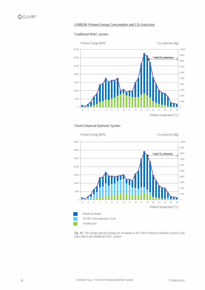
Let’s now move the traditional HVAC system in London from a gas boiler heating design to an all electric solution to produce cooling and heating capacity.
Due to opposite loads (space and primary air) at a time, a multifunction air sourced heat pump must be used in the traditional HVAC system, to provide chilled water and hot water at once.
TF14I001GB-02 Technical Focus · The Clivet Enhanced Hydronic System 30
Fig. 41: The energy input for primary air circulation in the Clivet Enhanced Hydronic System is far lower than in the traditional HVAC system
0
1000
2000
3000
4000
5000
6000
7000
8000
9000
10000
0
5000
10000
15000
20000
25000
30000
35000
-4 -2 0 2 4 6 8 10 12 14 16 18 20 22 24 26 28
Total CO2 emissions
Traditional HVAC system
Clivet Enhanced Hydronic System
LONDON: Primary Energy Consumption and CO2 Emissions
0
1000
2000
3000
4000
5000
6000
7000
8000
9000
10000
0
5000
10000
15000
20000
25000
30000
35000
-4 -2 0 2 4 6 8 10 12 14 16 18 20 22 24 26 28
Total CO2 emissions
Outdoor temperature [°C]
Primary Energy [kWh] CO2 emissions [kg]
Outdoor temperature [°C]
CO2 emissions [kg] Primary Energy [kWh]
Electric Generator
ZEPHIR3 Thermodynamic Circuit
Handling fans

TF14I001GB-02 31 Technical Focus · The Clivet Enhanced Hydronic System
CONCLUSIONS
The Clivet Enhanced Hydronic System is based on the high efficiency reversibile heat pump technology. It always proves to be more beneficial than traditional solutions, regardless climatic profile, heat recovery technology, cooling or heating technologies.
The dynamic year-round analysis on a typical multi-level office building application results in:
Overall energy saving over 30% in most locations in year round operation
Minimal carbon footprint: double-digit CO2 reduction results in more opportunities for tax reduction and building certification, thus raising the building overall value
Up to 42% saving on energy cost: this is a further profit opportunity in the whole lifetime of the building
Furthermore, additional benefits from the Clivet Enhanced Hydronic System are:
Total Indoor Air Quality: advanced Primary Air technology with high efficiency filtration allow best hygienic performance and higher productivity
Higher Leasable Area: compact design and minimal pipework reduce technical rooms and allow the best architectural integration
Effective capital cost: in most applications the whole system results in saving also on the first investment. Its modular design further allows to spread out the investment over time
Earlier earnings: as the Clivet Enhanced Hydronic System is highly integrated, on-site work can be effectively reduced. Spaces can be rented or sold much before it would usually happen.
Those benefits apply in many other residential, commercial and industrial applications. They are also effective with different local systems.
Fig. 42: the Clivet Enhanced Hydronic System is also effective in Hotels, Restaurants, Congress centres, Industrial buildings and in many other applications.

TF14I001GB-02 Technical Focus · The Clivet Enhanced Hydronic System 32
APPENDIX Detail of analysis with reference to the city of London. Comparison between Clivet Enhanced Hydronic System and a traditional HVAC system with stepless screw chillers and gas boilers. Winter/Summer indoor air d.b. temperature [°C]=20/25 - Winter/Summer indoor r.h. [%]=40/55 - Winter/Summer Primary Air supply d.b. temperature [°C]=22/20 - Supply / Return Primary Air fan available static pressure [Pa]= 250/150
Application Offices, London, office hours from 8 am to 8 pm, Monday to Friday, based on an annual cycle Data summarising by 5°C temperature ranges, the mean value is shown. Frequency of occurrence in hours "bin method". Yield distribution and regulation = 0.8 * 0.9 = 0.72
APPLICATION FEATURES TOTAL Outdoor d.b. temp. / r.h. °C / % -5 / 87 0 / 88 5 / 87 10 / 83 15 / 76 20 / 66 25 / 53 30 / 43 No. hours (Mon-Fri / 8-20) - Day operation h 7 193 626 975 906 573 108 5 3.393 Total space thermal load kW -125,8 -90,2 -46,4 16,6 96,4 197,8 229,4 262,2 TRADITIONAL SYSTEM AIR HANDLING UNIT (n.8 x 4.000 m3/h) ENTHALPY WHEEL RECOVERY Temperatur/Humidity efficiency % 71,7/ 57,8 71,7/ 57,8 71,7/ 57,8 71,7/ 57,8 71,7/ 57,8 OFF 69,3/44,5 69,3/44,5 Pressure drop enthalpy wheel - outdoor/exhaust air side Pa 123 / 129 125 / 130 128 / 131 130 / 132 133 / 134 139 / 139 139 / 139 140 / 140 Enthalpy wheel motor power input kW 0,04 0,04 0,04 0,04 0,04 OFF 0,04 0,04 Enthalpy wheel total capacity output kW 29,9 23,8 16,5 8,8 0,9 OFF 0,6 1,7 Air outlet enthalpy wheel d.b. temp. / r.u. °C 13,2 / 46 14,3 / 46 15,8 / 48 17,2 / 50 18,6 / 52 20 / 60 25,0 / 54 25,9 / 50 TREATMENT COIL (HOT AND COLD) Total cooling/heating capacity kW 11,7 10,3 8,3 6,4 4,5 OFF 18,4 15,6 Off coil dry bulb temperature °C 22,0 22,0 22,0 22,0 22,0 OFF 14,5 16,9 Off coil air humidity ratio g/kg 4,4 4,7 5,3 6,1 6,9 OFF 9,5 9,5 REHEATING T COIL Total sensible capacity kW OFF OFF OFF OFF OFF OFF 7,3 4,1 Supply air dry bulb temperature °C OFF OFF OFF OFF OFF OFF 20 20 Supply air humidity ratio g/kg OFF OFF OFF OFF OFF OFF 9,5 9,5 SUPPLY/EXHAUST FANS Supply fan power input kW 1,5 / 0,6 1,5 / 0,6 1,5 / 0,6 1,5 / 0,6 1,5 / 0,6 1,5 / 0,6 1,5 / 0,6 1,5 / 0,6 CENTRAL CHILLED WATER OFF OFF OFF COOLING COOLING COOLING COOLING COOLING Compressor efficiency - OFF OFF OFF 5,4 5,0 4,6 4,2 4,0 Cooling capacity kW OFF OFF OFF 23,1 133,9 274,7 523,1 538,0 Total power input kW 0,0 0,0 0,0 5,1 31,5 69,2 147,1 158,8 CENTRAL HOT WATER HEAT HEAT HEAT HEAT HEAT OFF HEAT HEAT Heating capacity kW 311,1 244,2 159,4 72,5 51,4 OFF 83,1 46,8 Total power input kW 4,7 3,7 2,3 0,8 0,6 0,0 0,5 0,5 ELECTRICITY ADSORBED Electricity absorbed - enthalpy wheel motor kWh 2 62 200 312 290 0 35 2 Electricity absorbed - supply fan kWh 84 2.316 7.512 11.700 10.872 6.876 1.296 60 Electricity absorbed - exhaust fan kWh 34 926 3.005 4.680 4.349 2.750 518 24 Electricity absorbed - Central chilled water kWh 0 0 0 4.974 28.514 39.633 15.882 794 Electricity absorbed - Central hot water kWh 38 29 18 7 5 0 4 4 METHANE GAS Methane gas Nm3 225 4.859 10.288 7.291 4.799 0 925 24 TOTAL PRIMARY ENERGY Total primary energy (2,18 kWh/kWhe) kWh 344 7.267 23.403 47.247 95.984 107.386 38.663 1.927
594.964
Total primary energy gas (9,6 kWh/Nm3) kWh 2.156 46.644 98.769 69.991 46.068 0 8.883 232 TOTAL CO2 EMISSIONS Total CO2 emissions (0,61 kgCO2/kWh_electric) kg CO2 96 2.033 6.549 13.220 26.858 30.048 10.818 539
142.437
Total CO2 emissions (1,84 kgCO2/Nm3) kg CO2 413 8.940 18.931 13.415 8.830 0 1.703 44 COST Electricity (0,15 EUR/kWh_electric) EUR 24 500 1.610 3.251 6.604 7.389 2.660 133
€ 44.900
Methane gas (0,80 EUR/Nm3) EUR 180 3.887 8.231 5.833 3.839 0 740 19 ENHANCED HYDRONIC SYSTEM ZEPHIR3 SYSTEM (n.8 x 4.000 m3/h) Total capacity kW 37,5 31,2 23,6 16,3 9,3 OFF 19,4 16,7 Reheat capacity from hot gas recovery kW - - - - - OFF 6,8 4,2 Compressor power input kW 6,6 4,7 3,2 2,1 1,3 OFF 2,8 2,5 Off coil dry bulb temperature °C 22,0 22,0 22,0 22,0 22,0 20,0 14,5 16,9 Supply air dry bulb temperature °C 22,0 22,0 22,0 22,0 22,0 20,0 20,0 20,0 Supply air humidity ratio g/kg 2,3 3,3 4,7 6,4 8,1 9,6 9,5 9,5 SUPPLY/EXHAUST FANS Supply/Exhaust fan power input kW 0,6 / 0,4 0,6 / 0,4 0,6 / 0,4 0,6 / 0,4 0,6 / 0,4 0,6 / 0,4 0,6 / 0,4 0,6 / 0,4 CENTRAL CHILLED/HOT WATER HEAT HEAT HEAT COOLING COOLING COOLING COOLING COOLING Compressor efficiency - 3,2 3,2 3,1 4,4 5,1 5,2 4,7 4,4 Cooling/heating capacity kW 174,7 125,3 64,4 23,1 133,9 274,7 318,7 364,2 Total power input kW 61,0 43,7 23,4 6,1 30,9 62,4 79,0 96,0 ELECTRICITY ADSORBED Electricity absorbed - ZEPHIR3 thermodynamic circuit kWh 367 7.180 15.976 16.692 9.231 0 2.454 100 Electricity absorbed - ZEPHIR3 supply fans kWh 34 926 3.005 4.680 4.349 2.750 518 24 Electricity absorbed - ZEPHIR3 exhaust fans kWh 22 618 2.003 3.120 2.899 1.834 346 16 Electricity absorbed - Central chilled/hot water kWh 427 8.437 14.627 5.929 27.997 35.732 8.532 480 TOTALA PRIMARY ENERGY Total primary energy (2,18 kWh/kWhe) kWh 1.852,0 37.410 77.631 66.319 96.956 87.889 25.833 1.352 395.242 Saving 34% TOTAL CO2 EMISSIONS Total CO2 emissions (0,61 kgCO2/kWh_electric) kg CO2 518 10.468 21.722 18.557 27.130 24.593 7.229 378 110.595 Saving 23% COST Electricity (0,15 EUR/kWh_electric) EUR 127 2.574 5.342 4.563 6.671 6.047 1.778 93 € 27.111 Saving 40%

TF14I001GB-02 33 Technical Focus · The Clivet Enhanced Hydronic System
Page intentionally left blank

TF14I001GB-02 Technical Focus · The Clivet Enhanced Hydronic System 34
Page intentionally left blank

TF14I001GB-02 35 Technical Focus · The Clivet Enhanced Hydronic System
Page intentionally left blank

www.clivet.com
TF14
G00
1GB-
02
CLIVET SPA Via Camp Lonc 25, Z.I. Villapaiera - 32032 Feltre (BL) - Italy Tel. + 39 0439 3131 - Fax + 39 0439 313300 - [email protected] CLIVET UK LTD 4 Kingdom Close, Segensworth East - Fareham, Hampshire - PO15 5TJ - United Kingdom Tel. + 44 (0) 1489 572238 - Fax + 44 (0) 1489 573033 - [email protected] CLIVET AIRCON LTD (Service and Maintenance Division) Units F5&F6 Railway Triangle Ind Est, Walton Road - Portsmouth, Hampshire - PO6 1TG - United Kingdom Tel. + 44 (0) 2392 381235 - Fax + 44 (0) 2392 381243 - [email protected] CLIVET ESPAÑA COMERCIAL S.L. (Sales) Calle Gurb, 17 1° 1a - 08500 Vic, Barcelona - España Tel. + 34 93 8606248 - Fax + 34 93 8855392 - [email protected] CLIVET ESPAÑA S.A.U.(Service and Maintenance Division) Calle Real de Burgos N° 12 - 28860, Paracuellos del Jarama, Madrid - España Tel. + 34 91 6658280 - Fax + 34 91 6657806 - [email protected] CLIVET GmbH Hummelsbütteler Steindamm 84, 22851 Norderstedt - Germany Tel. + 49 (0) 40 32 59 57-0 - Fax + 49 (0) 40 32 59 57-194 - [email protected] CLIVET NEDERLAND B.V. Siliciumweg 20a, 3812 SX Amersfoort - Netherlands Tel. + 31 (0) 33 7503420 - Fax + 31 (0) 33 7503424 - [email protected] CLIVET RUSSIA Elektrozavodskaya st. 24, office 509 - 107023, Moscow, Russia Tel. + 74956462009 - Fax + 74956462009 - [email protected] CLIVET MIDEAST FZCO Dubai Silicon Oasis (DSO), High Bay Complex, Ind Unit No. 3, PO BOX 28178 - Dubai, UAE Tel. + 9714 3208499 - Fax + 9714 3208216 - [email protected] CLIVET AIRCONDITIONING SYSTEMS PRIVATE LIMITED 4BA, Gundecha Onclave - Kherani Road, Saki Naka, Andheri (East) - Mumbai 400 072 - India Tel. + 91 22 6193 7000 - Fax + 91 22 6193 7001 - [email protected]