The BTeV Data Acquisition System
23
The BTeV Data Acquisition System RT-2003 May 22, 2002 Klaus Honscheid, OSU ¶ The BTeV Challenge ¶ The Project ¶ Readout and Controls
Transcript of The BTeV Data Acquisition System
K. Honscheid RT-2003
The BTeV Data Acquisition System
RT-2003May 22, 2002
Klaus Honscheid, OSU
¶ The BTeV Challenge¶ The Project¶ Readout and Controls
K. Honscheid RT-2003
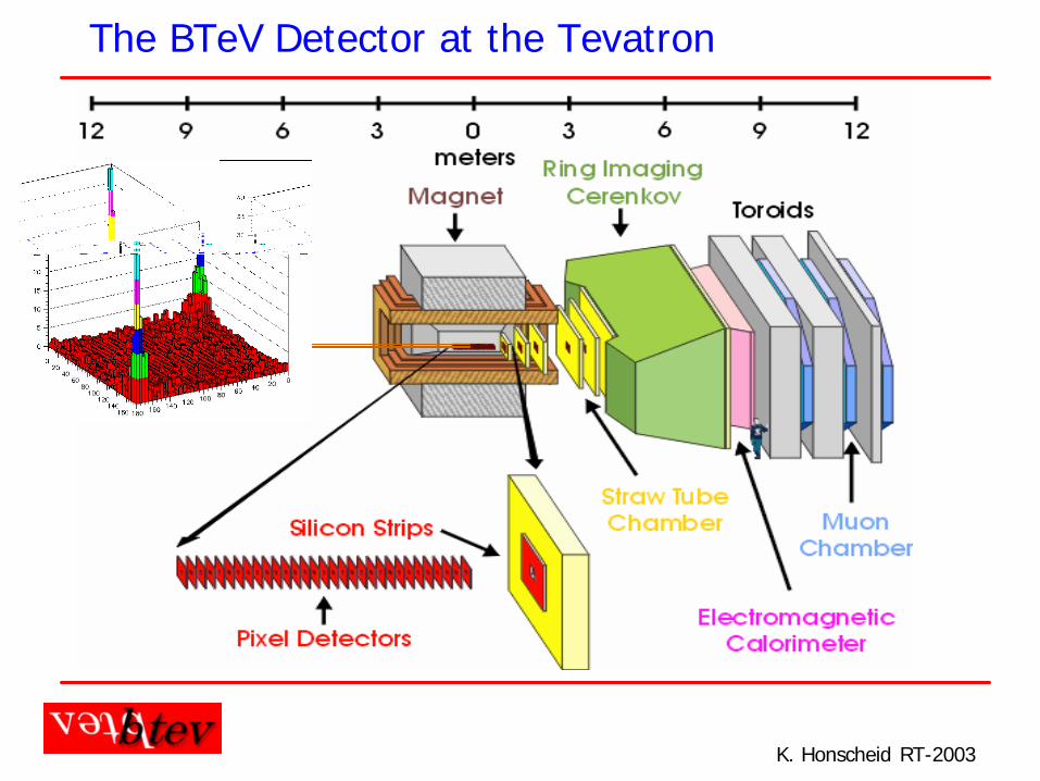
The BTeV Detector at the Tevatron
Beam Line
K. Honscheid RT-2003
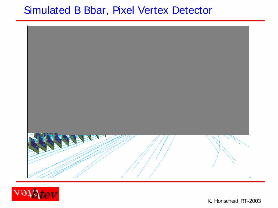
Simulated B Bbar, Pixel Vertex Detector
K. Honscheid RT-2003
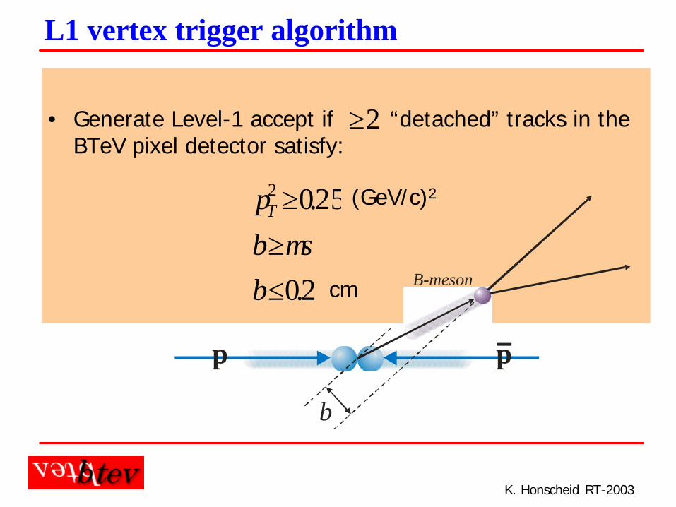
• Generate Level-1 accept if “detached” tracks in the BTeV pixel detector satisfy:
2≥
2.0
25.02
≤≥≥
bmb
pT
σ
(GeV/c)2
cm
L1 vertex trigger algorithm
b
p p
B-meson
K. Honscheid RT-2003
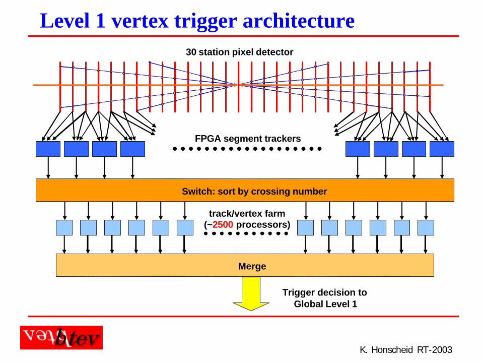
Level 1 vertex trigger architecture
FPGA segment trackers
Merge
Trigger decision to Global Level 1
Switch: sort by crossing number
track/vertex farm(~2500 processors)
30 station pixel detector
K. Honscheid RT-2003
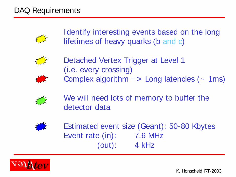
DAQ Requirements
Identify interesting events based on the longlifetimes of heavy quarks (b and c)
Detached Vertex Trigger at Level 1(i.e. every crossing)Complex algorithm => Long latencies (~ 1ms)
We will need lots of memory to buffer thedetector data
Estimated event size (Geant): 50-80 KbytesEvent rate (in): 7.6 MHz
(out): 4 kHz
K. Honscheid RT-2003
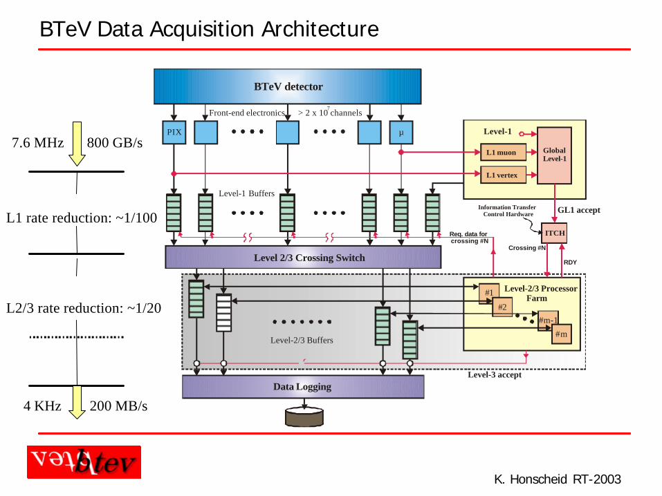
BTeV Data Acquisition Architecture
BTeV detector
L1 muon
L1 vertex
GlobalLevel-1
Level-1
Level 2/3 Crossing Switch
Data Logging
Front-end electronics
Level-1 Buffers
Level-2/3 Buffers
Information Transfer Control Hardware
ITCH
Level-2/3 Processor Farm
#1
#2#m-1
#m
RDY
Crossing #N
Req. data for crossing #N
Level-3 accept
GL1 accept
PIX µ
> 2 x 10 channels7
800 GB/s7.6 MHz
L1 rate reduction: ~1/100
L2/3 rate reduction: ~1/20
4 KHz 200 MB/s
K. Honscheid RT-2003
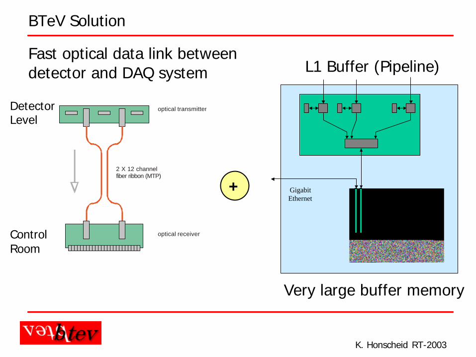
BTeV Solution
Fast optical data link betweendetector and DAQ system
Very large buffer memory
GigabitEthernet
2 X 12 channelfiber ribbon (MTP)
optical transmitter
optical receiver
+
DetectorLevel
ControlRoom
L1 Buffer (Pipeline)
K. Honscheid RT-2003
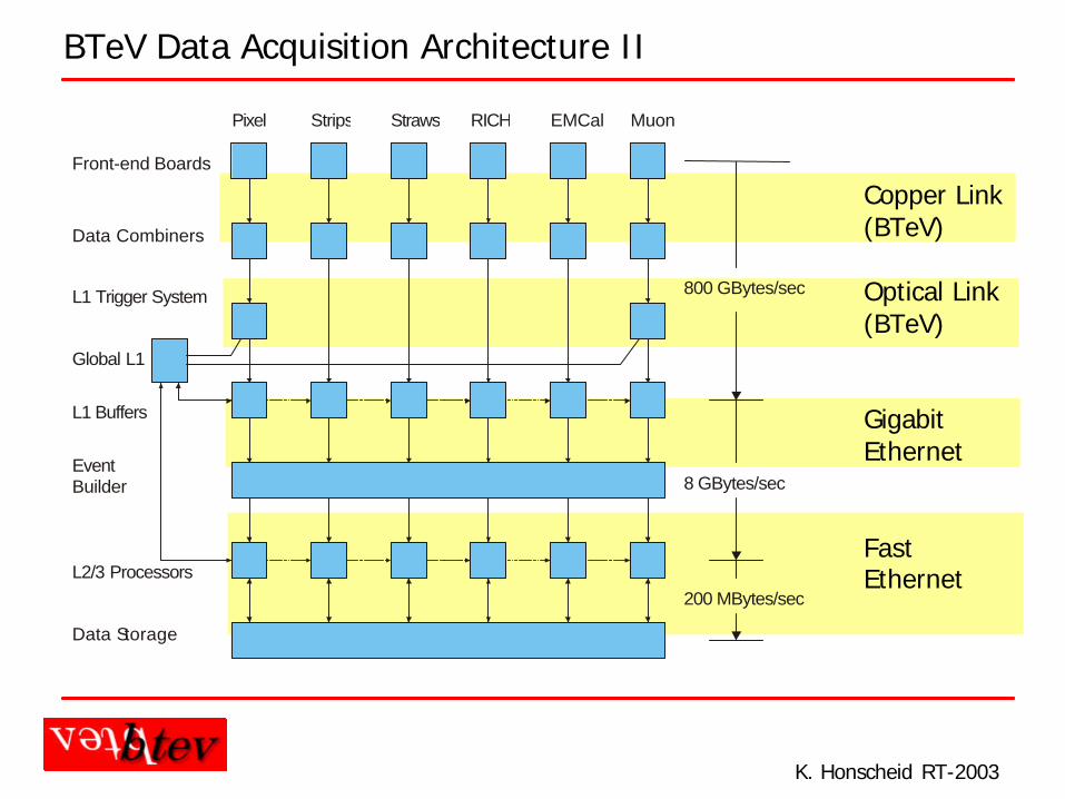
BTeV Data Acquisition Architecture II
Front-end Boards
Pixel Strips Straws RICH EMCal Muon
800 GBytes/sec
8 GBytes/sec
200 MBytes/sec
Data Combiners
L1 Trigger System
L1 Buffers
Global L1
EventBuilder
L2/3 Processors
Data Storage
Copper Link(BTeV)
Optical Link(BTeV)
GigabitEthernet
FastEthernet
K. Honscheid RT-2003
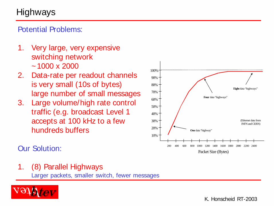
Highways
10%
20%
30%
40%
50%
60%
70%
80%
90%
100%
200 400 600 800 1000 1200 1400 1600 1800 2000
Packet Size (Bytes)
(Ethernet data fromINFN and CERN)
2200 2400
One data “highway”
Eight data “highways”
Four data “highways”
Potential Problems:
1. Very large, very expensiveswitching network~1000 x 2000
2. Data-rate per readout channelsis very small (10s of bytes)large number of small messages
3. Large volume/high rate controltraffic (e.g. broadcast Level 1accepts at 100 kHz to a few hundreds buffers
Our Solution:
1. (8) Parallel HighwaysLarger packets, smaller switch, fewer messages
K. Honscheid RT-2003
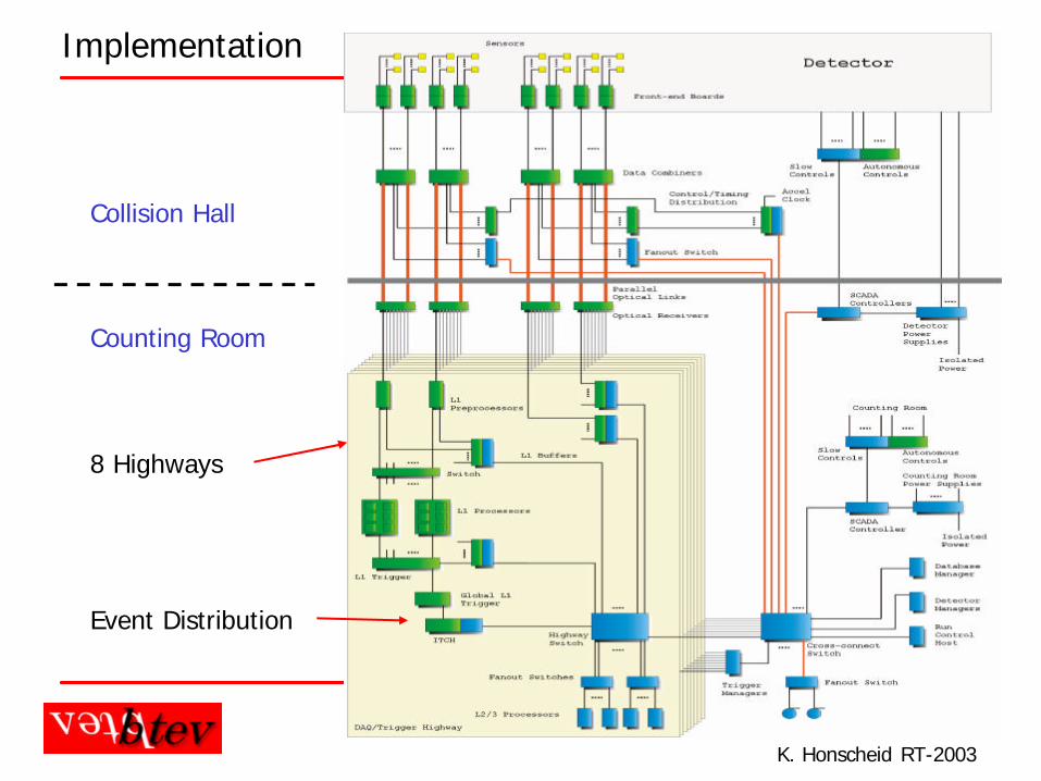
Implementation
Collision Hall
Counting Room
8 Highways
Event Distribution
K. Honscheid RT-2003
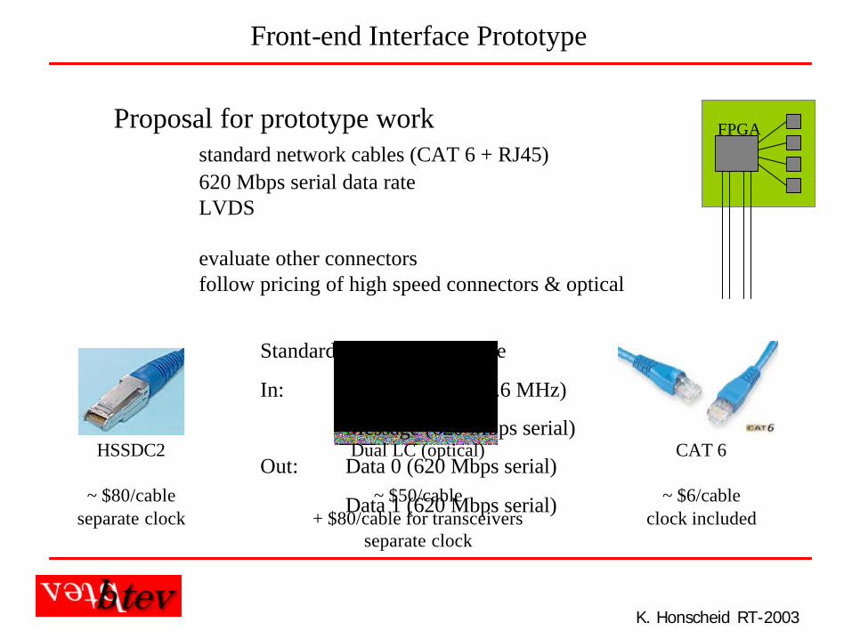
Front-end Interface Prototype
Proposal for prototype workstandard network cables (CAT 6 + RJ45)620 Mbps serial data rateLVDS
evaluate other connectorsfollow pricing of high speed connectors & optical
HSSDC2
~ $80/cableseparate clock
Dual LC (optical)
~ $50/cable+ $80/cable for transceivers
separate clock
CAT 6
~ $6/cableclock included
Standard FE digital interface
In: Crossing clock (7.6 MHz)
Message (620 Mbps serial)
Out: Data 0 (620 Mbps serial)
Data 1 (620 Mbps serial)
FPGA
K. Honscheid RT-2003
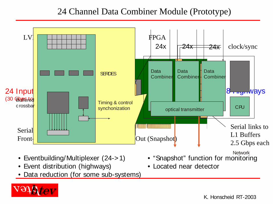
24 Channel Data Combiner Module (Prototype)
LVDS serializers/deserializers FPGA
Serial links to/fromFront-end Modules Local Data Out (Snapshot)
clock/sync
Serial links toL1 Buffers2.5 Gbps each
8 Highways24 Input Ports(30 Gbps tot. bandwidth)
• Eventbuilding/Multiplexer (24->1)• Event distribution (highways)• Data reduction (for some sub-systems)
• “Snapshot” function for monitoring• Located near detector
24x 24x 24x
optical transmitterTiming & controlsynchonization
Bufferedc rossbar
SERDES
Network
CPU
DataCombiner
DataCombiner
DataCombiner
3x8 channels
K. Honscheid RT-2003
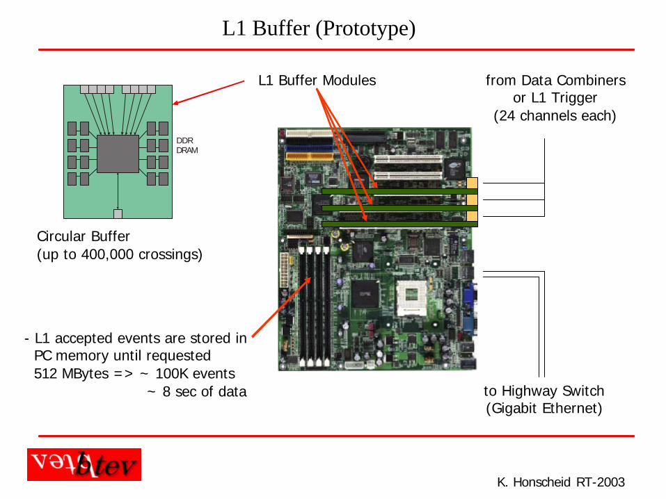
to Highway Switch(Gigabit Ethernet)
from Data Combinersor L1 Trigger
(24 channels each)
L1 Buffer Modules
L1 Buffer (Prototype)
- L1 accepted events are stored inPC memory until requested512 MBytes => ~ 100K events
~ 8 sec of data
DDRDRAM
Circular Buffer (up to 400,000 crossings)
K. Honscheid RT-2003
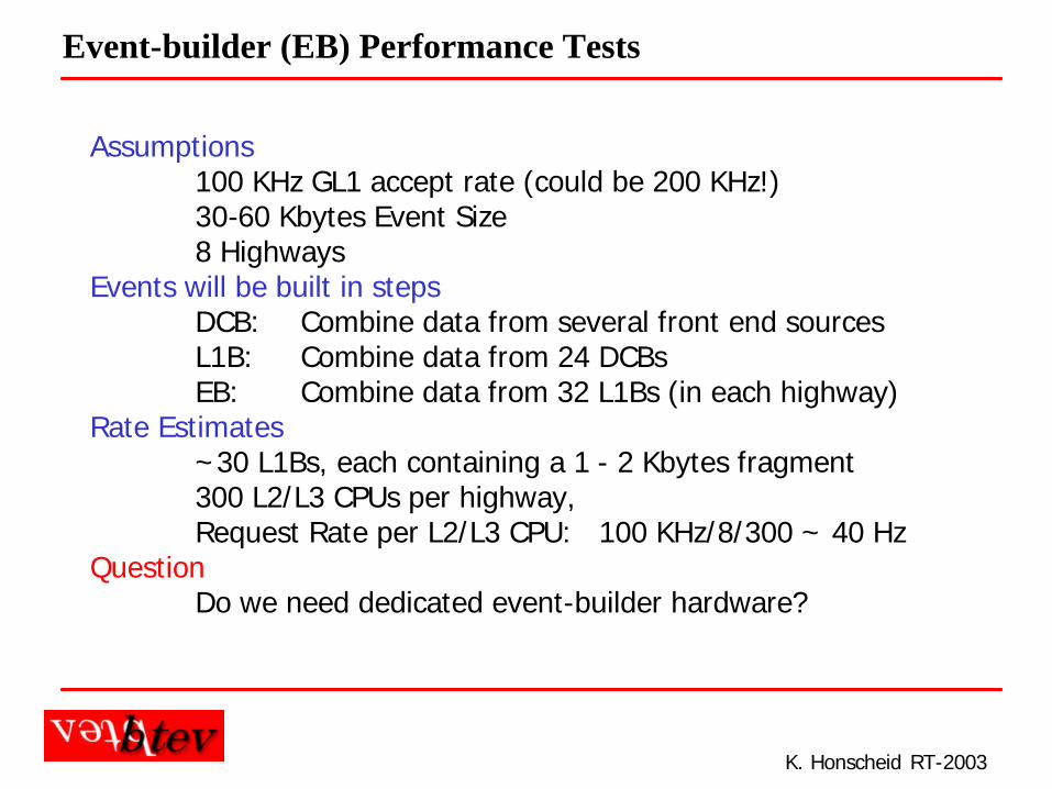
Event-builder (EB) Performance Tests
Assumptions100 KHz GL1 accept rate (could be 200 KHz!)30-60 Kbytes Event Size8 Highways
Events will be built in stepsDCB: Combine data from several front end sourcesL1B: Combine data from 24 DCBsEB: Combine data from 32 L1Bs (in each highway)
Rate Estimates~30 L1Bs, each containing a 1 - 2 Kbytes fragment300 L2/L3 CPUs per highway, Request Rate per L2/L3 CPU: 100 KHz/8/300 ~ 40 Hz
QuestionDo we need dedicated event-builder hardware?
K. Honscheid RT-2003
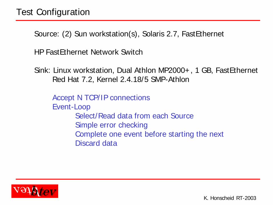
Test Configuration
Source: (2) Sun workstation(s), Solaris 2.7, FastEthernet
HP FastEthernet Network Switch
Sink: Linux workstation, Dual Athlon MP2000+, 1 GB, FastEthernetRed Hat 7.2, Kernel 2.4.18/5 SMP-Athlon
Accept N TCP/IP connectionsEvent-Loop
Select/Read data from each SourceSimple error checkingComplete one event before starting the nextDiscard data
K. Honscheid RT-2003
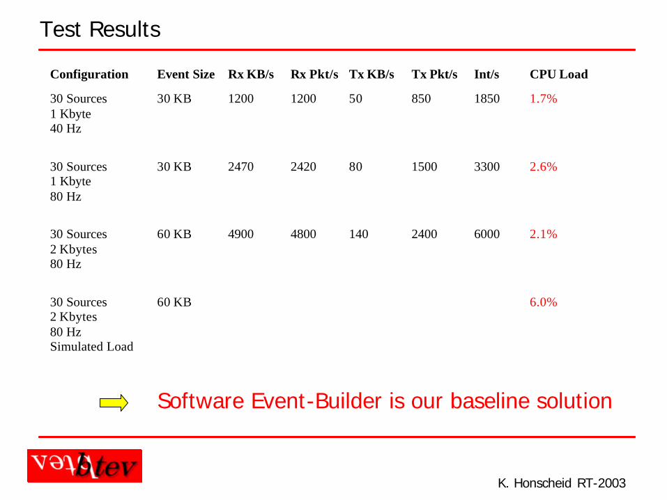
Test Results
Configuration Event Size Rx KB/s Rx Pkt/s Tx KB/s Tx Pkt/s Int/s CPU Load
30 Sources1 Kbyte40 Hz
30 KB 1200 1200 50 850 1850 1.7%
30 Sources1 Kbyte80 Hz
30 KB 2470 2420 80 1500 3300 2.6%
30 Sources2 Kbytes80 Hz
60 KB 4900 4800 140 2400 6000 2.1%
30 Sources2 Kbytes80 HzSimulated Load
60 KB 6.0%
Software Event-Builder is our baseline solution
K. Honscheid RT-2003
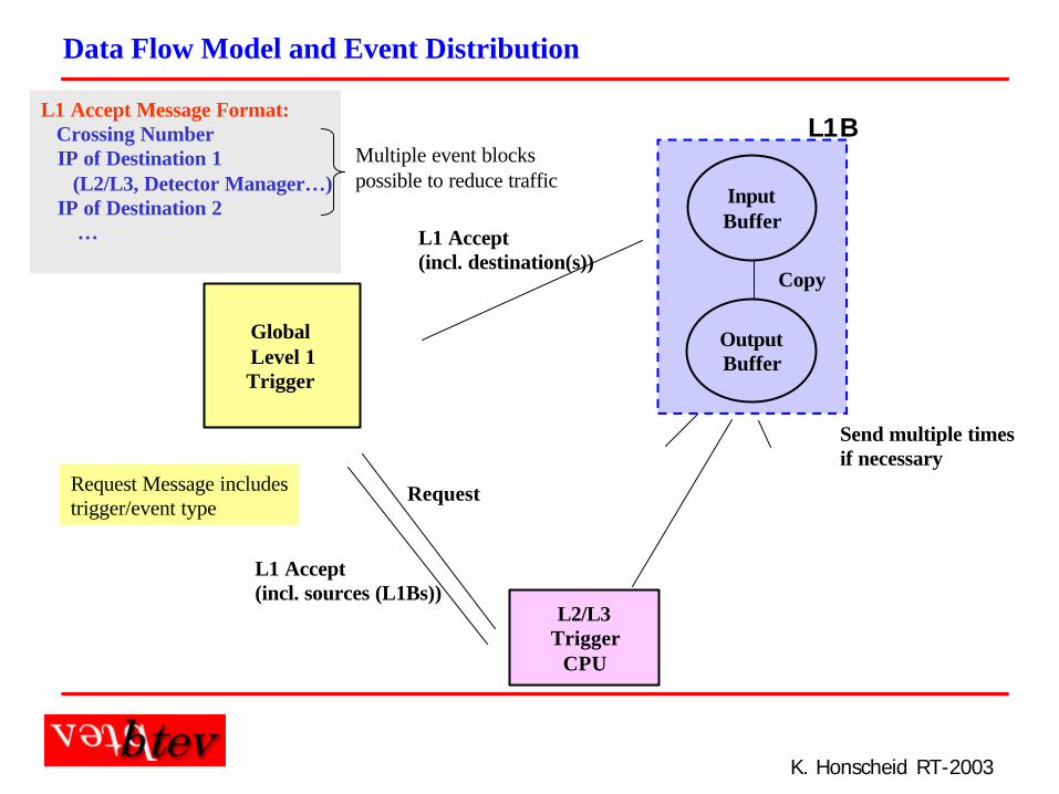
Data Flow Model and Event Distribution
Global Level 1Trigger
InputBuffer
OutputBuffer
L2/L3Trigger
CPU
L1B
L1 Accept(incl. destination(s))
Copy
Send multiple timesif necessary
Request
L1 Accept Message Format:Crossing NumberIP of Destination 1
(L2/L3, Detector Manager…)IP of Destination 2
…
L1 Accept(incl. sources (L1Bs))
Multiple event blockspossible to reduce traffic
Request Message includestrigger/event type
K. Honscheid RT-2003
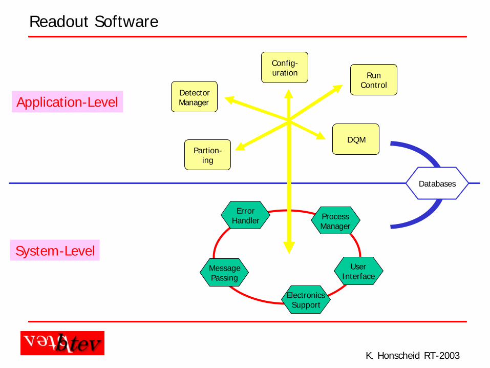
Readout Software
System-Level
Application-Level
MessagePassing
ElectronicsSupport
ProcessManager
UserInterface
ErrorHandler
DetectorManager
Partion-ing
Config-uration
DQM
RunControl
Databases
K. Honscheid RT-2003
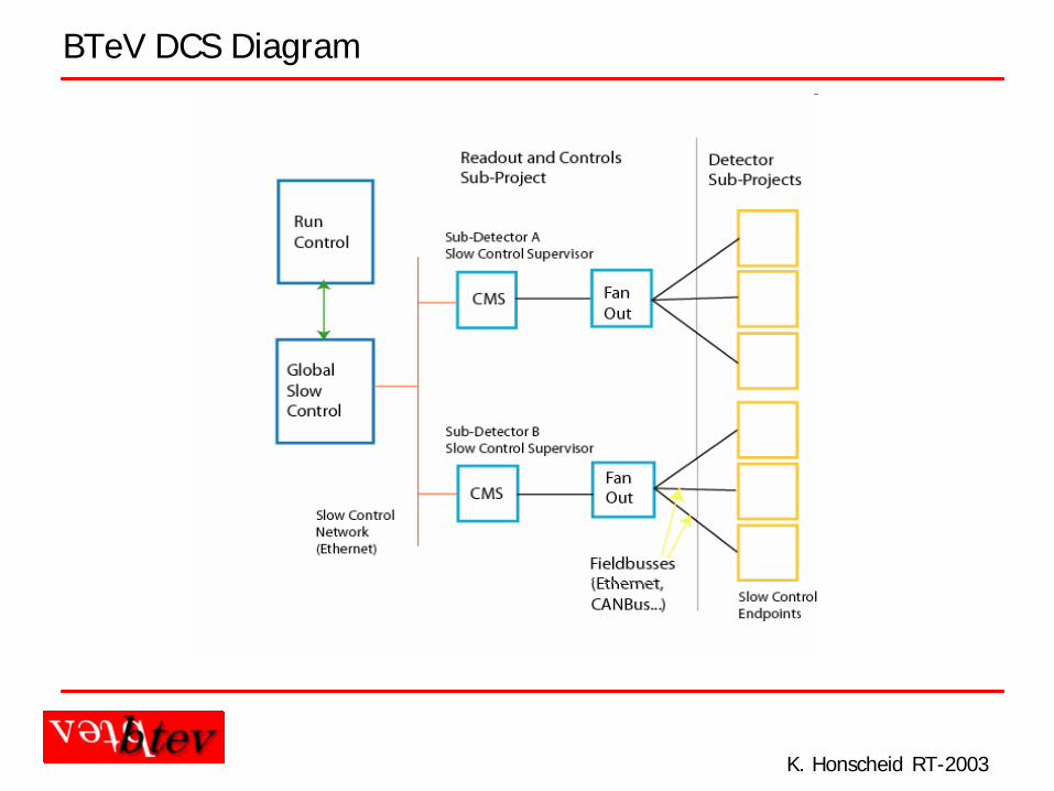
BTeV DCS Diagram
K. Honscheid RT-2003
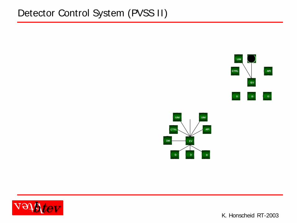
Detector Control System (PVSS II)
CTRLCTRL APIAPI
EVEV
DD DDDD
UIMUIM UIMUIM
DMDM
CTRLCTRL APIAPI
EVEV
DD DDDD
UIMUIM
U I MU I MD
Control Room
Local Monitoring
CTRLCTRL APIAPI
EVEV
DD DDDD
UIMUIM UIMUIM
DMDM
CTRLCTRL APIAPI
EVEV
DD DDDD
UIMUIM UIMUIM UIMUIM
DMDM
CTRLCTRL APIAPI
EVEV
DD DDDD
UIMUIM UIMUIM
U I MD MD MD I S T D I S TD I S T D I S TD I S T
Control Room
Local Monitoring
Strong Support by CERN
Workshop at FNAL(March 2002)
Support for Windowsand Linux
Support for distributedcontrol architectures
Oracle Interface
Evaluation Licensesavailable
K. Honscheid RT-2003
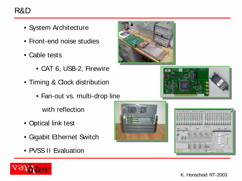
R&D
• System Architecture
• Front-end noise studies
• Cable tests
• CAT 6, USB-2, Firewire
• Timing & Clock distribution
• Fan-out vs. multi-drop line
with reflection
• Optical link test
• Gigabit Ethernet Switch
• PVSS II Evaluation
K. Honscheid RT-2003
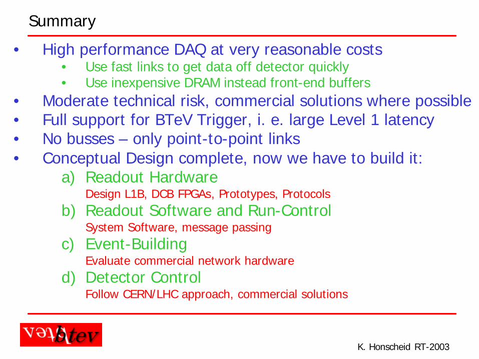
Summary
• High performance DAQ at very reasonable costs• Use fast links to get data off detector quickly• Use inexpensive DRAM instead front-end buffers
• Moderate technical risk, commercial solutions where possible• Full support for BTeV Trigger, i. e. large Level 1 latency• No busses – only point-to-point links • Conceptual Design complete, now we have to build it:
a) Readout HardwareDesign L1B, DCB FPGAs, Prototypes, Protocols
b) Readout Software and Run-ControlSystem Software, message passing
c) Event-BuildingEvaluate commercial network hardware
d) Detector ControlFollow CERN/LHC approach, commercial solutions