The ARM Assembly Language Programming
112
Assembly Language, CSIE, CCU 1 The ARM Assembly Language Programming Peng-Sheng Chen
Transcript of The ARM Assembly Language Programming
Assembly Language, CSIE, CCU1
The ARM Assembly
Language Programming
Peng-Sheng Chen
Assembly Language, CSIE, CCU2
Introduction (1)
• The ARM processor is easy to program at the
assembly level
• In this study, we will
– Look at ARM assembly language
programming at the user level
– See how to write simple programs which
will run on an ARM development board /
ARM emulator
Assembly Language, CSIE, CCU
Introduction (2)
• Study 32-bit ARM instruction set
• Target: ARM v4T
3
➢ Load-store architecture.
➢ Only load and store instructions can access
memory.
➢ Data processing instructions operate on
register contents only.

Assembly Language, CSIE, CCU4
Outline
• Data processing instructions
• Data transfer instructions
• Control flow instructions
• Writing simple assembly language
programs

Assembly Language, CSIE, CCU5
Outline
• Data processing instructions
• Data transfer instructions
• Control flow instructions
• Writing simple assembly language
programs
Assembly Language, CSIE, CCU6
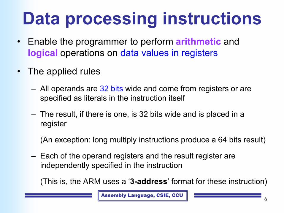
Data processing instructions• Enable the programmer to perform arithmetic and
logical operations on data values in registers
• The applied rules
– All operands are 32 bits wide and come from registers or are
specified as literals in the instruction itself
– The result, if there is one, is 32 bits wide and is placed in a
register
(An exception: long multiply instructions produce a 64 bits result)
– Each of the operand registers and the result register are
independently specified in the instruction
(This is, the ARM uses a ‘3-address’ format for these instruction)

Assembly Language, CSIE, CCU7
ADD r0, r1, r2 @ r0 := r1 + r2
Simple Register Operands
The at sign here indicates that everything to the right of it is
a comment and should be ignored by the assembler (GAS)
• Multi-line comments: /* … */

Assembly Language, CSIE, CCU8
Arithmetic Operations
• These instructions perform binary arithmetic on two 32-
bit operands
• The carry-in, when used, is the current value of the C bit
in the CPSR
ADD r0, r1, r2 r0 := r1 + r2
ADC r0, r1, r2 r0 := r1 + r2 + C
SUB r0, r1, r2 r0 := r1 – r2
SBC r0, r1, r2 r0 := r1 – r2 + C – 1
RSB r0, r1, r2 r0 := r2 – r1
RSC r0, r1, r2 r0 := r2 – r1 + C – 1

Assembly Language, CSIE, CCU9
Current Program Status Registers
(CPSR)

Assembly Language, CSIE, CCU10
Bit-Wise Logical Operations
• These instructions perform the specified boolean logic
operation on each bit pair of the input operands
AND r0, r1, r2 r0 := r1 AND r2
ORR r0, r1, r2 r0 := r1 OR r2
EOR r0, r1, r2 r0 := r1 XOR r2
BIC r0, r1, r2 r0 := r1 AND (NOT r2)
r0[i] := r1[i] OPlogic r2[i] for i in [0..31]
• BIC stands for ‘bit clear’
• Every ‘1’ in the second operand clears the corresponding
bit in the first

Assembly Language, CSIE, CCU11
Example: BIC Instruction
• r1 = 1111111111111111
r2 = 0000000001100101
BIC r0, r1, r2
• r0 = 1111111110011010
Assume that r1, r2, and r0 are 16-bit registers

Assembly Language, CSIE, CCU12
Register Movement Operations
• These instructions ignore the first operand, which is
omitted from the assembly language format, and simply
move the second operand to the destination
MOV r0, r2 r0 := r2
MVN r0, r2 r0 := NOT r2

Assembly Language, CSIE, CCU13
Comparison Operations
• These instructions do not produce a result, but just set
the condition code bits (N, Z, C, and V) in the CPSR
according to the selected operation
CMP r1, r2 compare set cc on r1 – r2
CMN r1, r2 compare negated set cc on r1 + r2
TST r1, r2 bit test set cc on r1 AND r2
TEQ r1, r2 test equal set cc on r1 XOR r2

Assembly Language, CSIE, CCU14
Immediate Operands
• If we wish to add a constant to a register, we can replace
the second source operand with an immediate value
ADD r3, r3, #1 ; r3 := r3 + 1
AND r8, r7, #0xff ; r8 := r7[7:0]
A constant preceded by ‘#’
A hexadecimal by putting ‘0x’ after the ‘#’
Immediate addressing mode

Assembly Language, CSIE, CCU15
Shifted Register Operands (1)
• These instructions allows the second register operand
to be subject to a shift operation before it is combined
with the first operand
• They are still single ARM instructions, executed in a
single clock cycle.
• Most processors offer shift operations as separate
instructions, but the ARM combines them with a general
ALU operation in a single instruction
ADD r3, r2, r1, LSL #3 ; r3 := r2 + 8 * r1

Assembly Language, CSIE, CCU16
Shifted Register Operands (2)
LSL logical shift left by 1 to 31 Fill the vacated bits at the LSB
of the word with zeros
ASL arithmetic shift left A synonym for LSL
XXXXX
00000
031
LSL #5

Assembly Language, CSIE, CCU17
Shifted Register Operands (3)
LSR logical shift right by 1 to 32 Fill the vacated bits at the MSB
of the word with zeros
XXXXX
00000
031
LSR #5

Assembly Language, CSIE, CCU18
Shifted Register Operands (4)
ASR arithmetic shift right by 1 to 32 Fill the vacated bits at the
MSB of the word with zero
(source operand is positive)
0
00000 0
031
ASR #5 ;positive operand

Assembly Language, CSIE, CCU19
Shifted Register Operands (5)
ASR arithmetic shift right by 1 to 32 Fill the vacated bits at the
MSB of the word with one
(source operand is negative)
1
11111 1
031
ASR #5 ;negative operand

Assembly Language, CSIE, CCU
Unsigned Integer
• 16 bit
– 0000000000000000 => 0
– 1111111111111111 => 2^16 – 1 = 65535
20

Assembly Language, CSIE, CCU
Signed Integer (2’s Complement)
• 32767 => 0111111111111111 (最大正數)
• 4 => 0000000000000100
• 1 => 0000000000000001
• 0 => 0000000000000000
• -1 => 1111111111111111
• -8 => 1111111111111000
• -32767 => 1000000000000001
• -32768 => 1000000000000000 (最小負數)
21
Assembly Language, CSIE, CCU
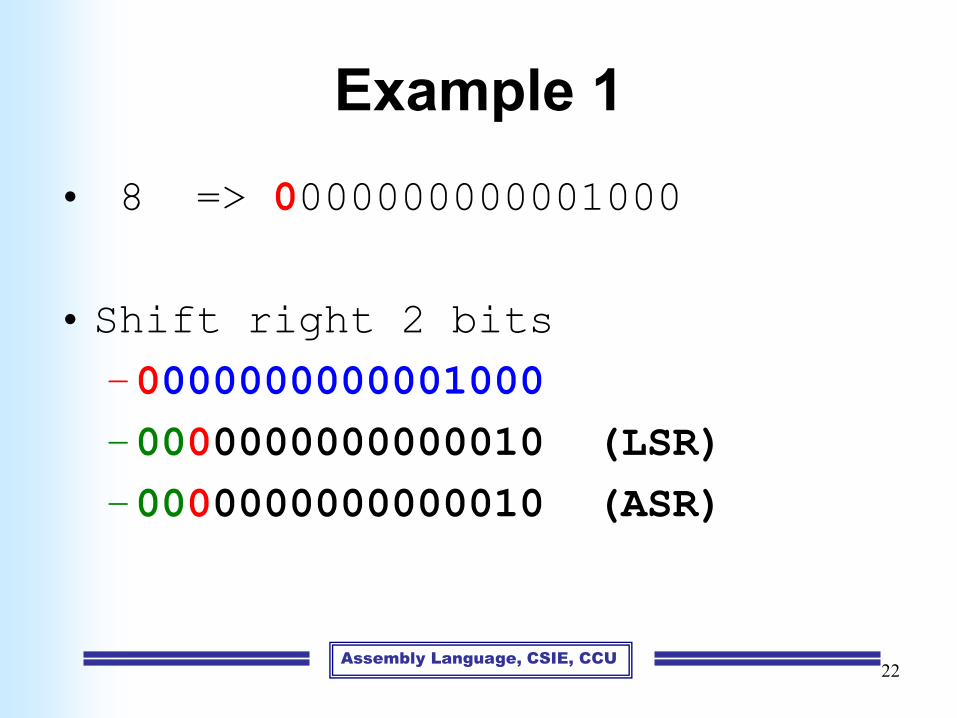
Example 1
• 8 => 0000000000001000
• Shift right 2 bits
–0000000000001000
–0000000000000010 (LSR)
–0000000000000010 (ASR)
22

Assembly Language, CSIE, CCU
Example 2
• -8 => 1111111111111000
• Shift right 2 bits
–1111111111111000
–0011111111111110 (LSR)
–1111111111111110 (ASR)
23
Assembly Language, CSIE, CCU24
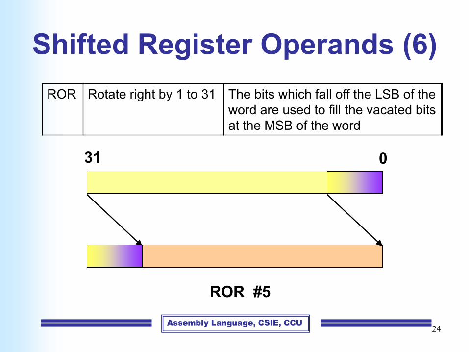
Shifted Register Operands (6)
ROR Rotate right by 1 to 31 The bits which fall off the LSB of the
word are used to fill the vacated bits
at the MSB of the word
031
ROR #5

Assembly Language, CSIE, CCU25

Assembly Language, CSIE, CCU26
Shifted Register Operands (7)
RRX Rotate right extended by 1
place
The vacated bit (bit 31) is filled
with the old value of the C flag
and the operand is shifted one
place to the right
C
031
RRX
C
C

Assembly Language, CSIE, CCU27

Assembly Language, CSIE, CCU28
Shifted Register Operands (8)
• It is possible to use a register value to specify the
number of bits the second operand should be shifted by
• Ex:
• Only the bottom 8 bits of r2 are significant
ADD r5, r5, r3, LSL r2 ; r5:=r5+r3*2^r2

Assembly Language, CSIE, CCU
OP Rd, Rn, Rm
29
ADD r3, r2, r1, LSL #0 ; r3 := r2 + r1
ADD r3, r2, r1 ; r3 := r2 + r1
• If omitted, no shift occurs, equivalent to LSL #0.
• If you omit the shift, or specify LSL #0, the instruction
uses the value in Rm.

Assembly Language, CSIE, CCU30
Setting the Condition Codes
• Any data processing instruction can set the condition
codes ( N, Z, C, and V) if the programmer wishes it to
• Ex: 64-bit addition
r0r1
r2r3+
r2r3
ADDS r2, r2, r0 ; 32-bit carry out->C
ADC r3, r3, r1 ; C is added into
; high word
Adding ‘S’ to the opcode, standing for ‘Set
condition codes’

Assembly Language, CSIE, CCU31
Multiplies (1)
• A special form of the data processing instruction
supports multiplication
• Some important differences
– Immediate second operands are not supported
– The result register must not be the same as the first source
register
– If the ‘S’ bit is set, the C flag is meaningless
MUL r4, r3, r2 ; r4 := (r3 x r2)[31:0]

Assembly Language, CSIE, CCU32
Multiplies (2)• The multiply-accumulate instruction
• In some cases, it is usually more efficient to use a short
series of data processing instructions
• Ex: multiply r0 by 3
MLA r4, r3, r2, r1 ; r4 := (r3 x r2 + r1)[31:0]
ADD r3, r0, r0, LSL #1 ;r3:= r0 + r0 x 2
; move 3 to r1
MUL r3, r0, r1 ; r3 := r0 x 3
OR

Assembly Language, CSIE, CCU33
Multiplies (3)• Ex: multiply r0 by 2
• Ex: multiply r0 by 35
ADD r0, r0, r0, LSL #2 ; r0’ := 5 x r0
RSB r3, r0, r0, LSL #3 ; r0’’:= 7 x r0’
; move 35 to r1
MUL r3, r0, r1 ; r3 := r0 x 35
OR
MOV r3, r0, LSL #1 ; r3 := r0 x 2
; move 2 to r1
MUL r3, r0, r1 ; r3 := r0 x 2
OR

Assembly Language, CSIE, CCU34
Outline
• Data processing instructions
• Data transfer instructions
• Control flow instructions
• Writing simple assembly language
programs

Assembly Language, CSIE, CCU35
Addressing mode
• The ARM data transfer instructions are all based
around register-indirect addressing
– Based-plus-offset addressing
– Based-plus-index addressing
LDR r0, [r1] ; r0 := mem32[r1]
STR r0, [r1] ; mem32[r1] := r0
Register-indirect addressing

Assembly Language, CSIE, CCU36
Data Transfer Instructions
• Move data between ARM registers and memory
• Three basic forms of data transfer instruction
– Single register load and store instructions
– Multiple register load and store instructions
– Single register swap instructions

Assembly Language, CSIE, CCU37
Single Register Load and Store
Instructions (1)
• These instructions provide the most flexible way
to transfer single data item between an ARM
register and memory
• The data item may be a byte, a 32-bit word, 16-
bit half-word
LDR r0, [r1] ; r0 := mem32[r1]
STR r0, [r1] ; mem32[r1] := r0
Register-indirect addressing
Assembly Language, CSIE, CCU38
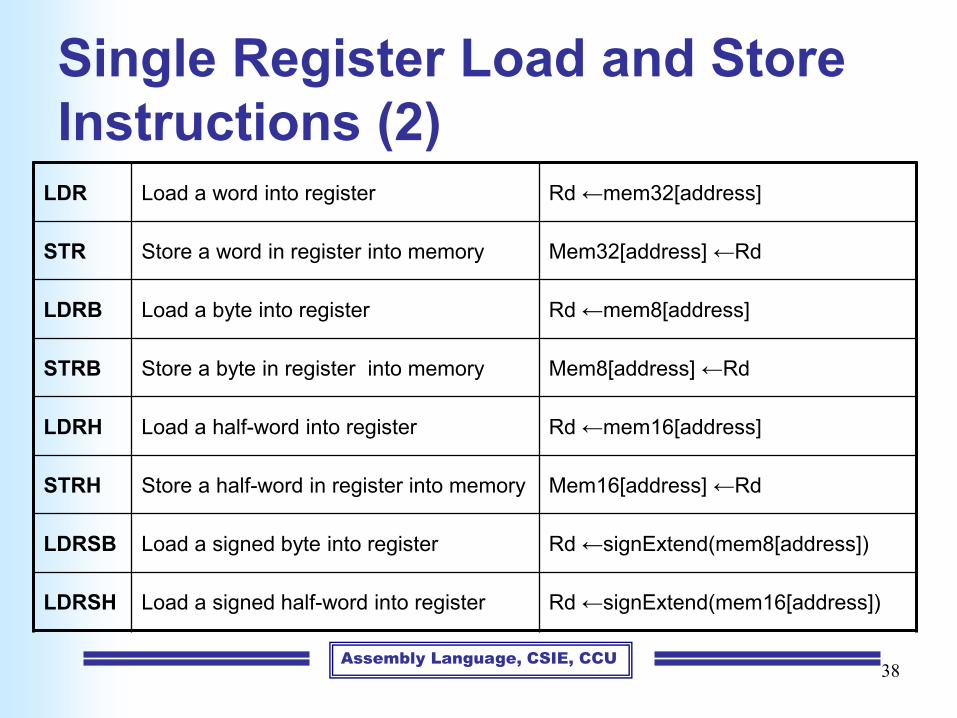
Single Register Load and Store
Instructions (2)LDR Load a word into register Rd ←mem32[address]
STR Store a word in register into memory Mem32[address] ←Rd
LDRB Load a byte into register Rd ←mem8[address]
STRB Store a byte in register into memory Mem8[address] ←Rd
LDRH Load a half-word into register Rd ←mem16[address]
STRH Store a half-word in register into memory Mem16[address] ←Rd
LDRSB Load a signed byte into register Rd ←signExtend(mem8[address])
LDRSH Load a signed half-word into register Rd ←signExtend(mem16[address])

Assembly Language, CSIE, CCU39
Endianess Example
Little-endian
r1 = 0x100
r0 = 0x1122334431 24 23 16 15 8 7 0
11 22 33 44
31 24 23 16 15 8 7 0
11 22 33 44
31 24 23 16 15 8 7 0
00 00 00 44
r2 = 0x44
STR r0, [r1]
LDRB r2, [r1]
Memory
From: The ARM Instruction Set - ARM University Program - V1.0
0x103
Assembly Language, CSIE, CCU40
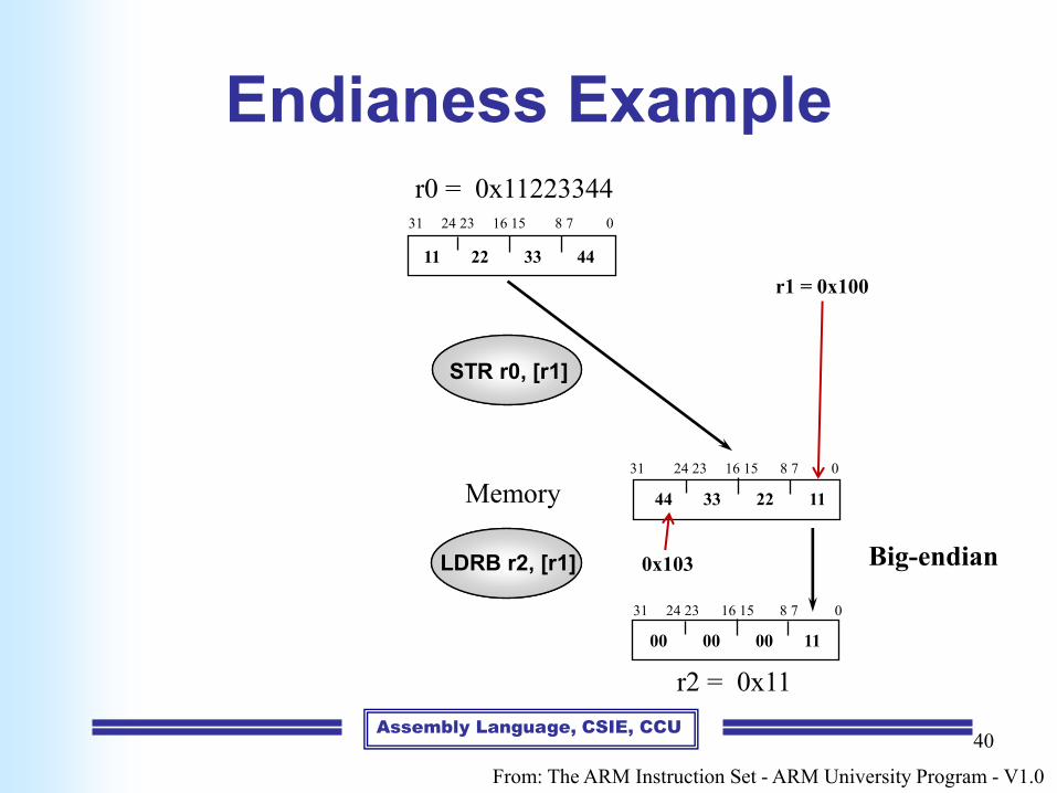
Endianess Example
Big-endian
r0 = 0x1122334431 24 23 16 15 8 7 0
11 22 33 44
31 24 23 16 15 8 7 0
44 33 22 11
31 24 23 16 15 8 7 0
00 00 00 11
r2 = 0x11
STR r0, [r1]
LDRB r2, [r1]
Memory
From: The ARM Instruction Set - ARM University Program - V1.0
r1 = 0x100
0x103

Assembly Language, CSIE, CCU41
Endianess Example
Big-endianLittle-endian
r1 = 0x100
r0 = 0x1122334431 24 23 16 15 8 7 0
11 22 33 44
31 24 23 16 15 8 7 0
11 22 33 44
31 24 23 16 15 8 7 0
44 33 22 11
31 24 23 16 15 8 7 0
00 00 00 44
31 24 23 16 15 8 7 0
00 00 00 11
r2 = 0x44 r2 = 0x11
STR r0, [r1]
LDRB r2, [r1]
Memory
From: The ARM Instruction Set - ARM University Program - V1.0
0x103
r1 = 0x100
0x103

Assembly Language, CSIE, CCU42
Base-plus-offset Addressing (1)
• Pre-indexed addressing mode
– It allows one base register to be used to access a
number of memory locations which are in the same
area of memory
LDR r0, [r1, #4] ; r0 := mem32[r1 + 4]

Assembly Language, CSIE, CCU43
Base-plus-offset Addressing (2)
• Auto-indexing (Preindex with writeback)
– No extra time
– The time and code space cost of the extra instruction
are avoided
LDR r0, [r1, #4]! ; r0 := mem32[r1 + 4]
; r1 := r1 + 4
The exclamation “!” mark indicates that the instruction should
update the base register after initiating the data transfer

Assembly Language, CSIE, CCU44
Base-plus-offset Addressing (3)
• Post-indexed addressing mode
– The exclamation “!” is not needed
LDR r0, [r1], #4 ; r0 := mem32[r1]
; r1 := r1 + 4
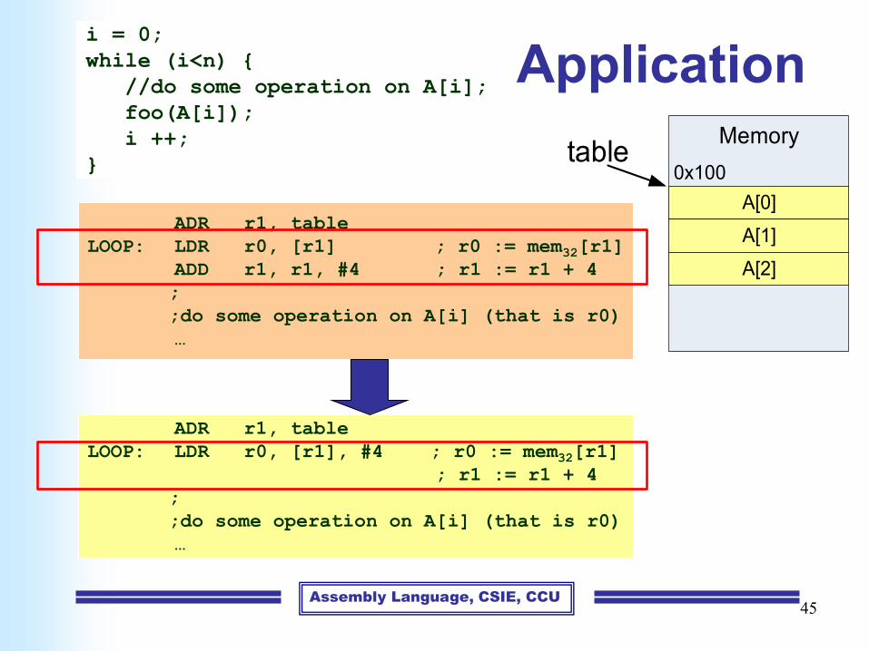
Assembly Language, CSIE, CCU45
ApplicationMemory
A[0]
0x100
A[1]
A[2]
table
ADR r1, table
LOOP: LDR r0, [r1], #4 ; r0 := mem32[r1]
; r1 := r1 + 4
;
;do some operation on A[i] (that is r0)
…
ADR r1, table
LOOP: LDR r0, [r1] ; r0 := mem32[r1]
ADD r1, r1, #4 ; r1 := r1 + 4
;
;do some operation on A[i] (that is r0)
…
i = 0;
while (i<n) {
//do some operation on A[i];
foo(A[i]);
i ++;
}

Assembly Language, CSIE, CCU46
Example
• Pre-indexed addressing mode
• Auto-indexing (Preindex with writeback)
• Post-indexed addressing mode
LDR r0, [r1, #8] ; r0 := mem32[r1 + 8]
LDR r0, [r1, #8]! ; r0 := mem32[r1 + 8]
; r1 := r1 + 8
LDR r0, [r1], #8 ; r0 := mem32[r1]
; r1 := r1 + 8

Assembly Language, CSIE, CCU
47
Multiple Register Load and Store
Instructions (1)
• Enable large quantities of data to be transferred
more efficiently
• They are used for procedure entry and exit to
save and restore workspace registers
• Copy blocks of data around memory
LDMIA r1, {r0, r2, r5} ; r0 := mem32[r1]
; r2 := mem32[r1 + 4]
; r5 := mem32[r1 + 8]
The base register r1 should be word-aligned

Assembly Language, CSIE, CCU48
Multiple Register Load and Store
Instructions (2)LDM Load multiple registers
STM Store multiple registers
Addressing mode Description Starting address End address Rn!
IA (increase after) 執行後增加 Rn Rn+4*N-4 Rn+4*N
IB (increase before) 執行前增加 Rn+4 Rn+4*N Rn+4*N
DA (decrease after) 執行後減少 Rn-4*Rn+4 Rn Rn-4*N
DB (decrease before) 執行前減少 Rn-4*N Rn-4 Rn-4*N
Addressing mode for multiple register load and store instructions

Assembly Language, CSIE, CCU49
Example (1)
0x100
0x104
0x108
0x10C
0x110
0x114
10
20
30
40
50
60
address data
r0
LDMIA r0, {r1, r2, r3}
OR
LDMIA r0, {r1-r3}
r1 := 10
r2 := 20
r3 := 30
r0 := 0x100

Assembly Language, CSIE, CCU50
Example (2)
0x100
0x104
0x108
0x10C
0x110
0x114
10
20
30
40
50
60
address data
r0
LDMIA r0!, {r1, r2, r3}
r1 := 10
r2 := 20
r3 := 30
r0 := 0x10C

Assembly Language, CSIE, CCU51
Example (3)
0x100
0x104
0x108
0x10C
0x110
0x114
10
20
30
40
50
60
address data
r0
LDMIB r0!, {r1, r2, r3}
r1 := 20
r2 := 30
r3 := 40
r0 := 0x10C

Assembly Language, CSIE, CCU52
Example (4)
0x100
0x104
0x108
0x10C
0x110
0x114
10
20
30
40
50
60
address data
r0
LDMDA r0!, {r1, r2, r3}
r1 := 40
r2 := 50
r3 := 60
r0 := 0x108

Assembly Language, CSIE, CCU53
Example (5)
0x100
0x104
0x108
0x10C
0x110
0x114
10
20
30
40
50
60
address data
r0
LDMDB r0!, {r1, r2, r3}
r1 := 30
r2 := 40
r3 := 50
r0 := 0x108

Assembly Language, CSIE, CCU54
Example (6)
0x100
0x104
0x108
0x10C
0x110
0x114
1
2
3
40
50
60
address data
r0
STMIA r0, {r1, r2, r3}
OR
STMIA r0, {r1-r3}
r1 := 1
r2 := 2
r3 := 3
r0 := 0x100

Assembly Language, CSIE, CCU55
Example (7)
0x100
0x104
0x108
0x10C
0x110
0x114
1
2
3
40
50
60
address data
r0
STMIA r0!, {r1, r2, r3}
OR
STMIA r0!, {r1-r3}
r1 := 1
r2 := 2
r3 := 3
r0 := 0x100
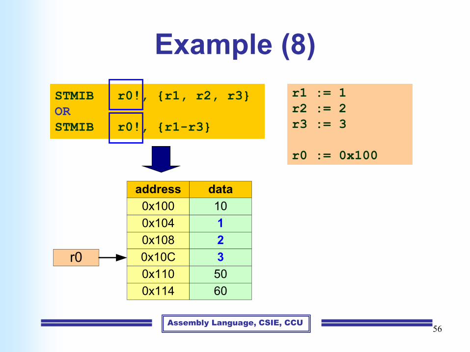
Assembly Language, CSIE, CCU56
Example (8)
0x100
0x104
0x108
0x10C
0x110
0x114
10
1
2
3
50
60
address data
r0
STMIB r0!, {r1, r2, r3}
OR
STMIB r0!, {r1-r3}
r1 := 1
r2 := 2
r3 := 3
r0 := 0x100

Assembly Language, CSIE, CCU57
Example (9)
0x100
0x104
0x108
0x10C
0x110
0x114
10
20
1
2
3
60
address data
r0
STMDA r0!, {r1, r2, r3}
OR
STMDA r0!, {r1-r3}
r1 := 1
r2 := 2
r3 := 3
r0 := 0x110

Assembly Language, CSIE, CCU58
Example (10)
0x100
0x104
0x108
0x10C
0x110
0x114
10
1
2
3
50
60
address data
r0
STMDB r0!, {r1, r2, r3}
OR
STMDB r0!, {r1-r3}
r1 := 1
r2 := 2
r3 := 3
r0 := 0x110

Assembly Language, CSIE, CCU59
Multiple Register Load and Store
Instructions (3)
• Base register used to determine where memory
access should occur
– 4 different addressing modes allow increment and
decrement inclusive or exclusive of the base register
location.
– Base register can be optionally updated following the
transfer by appending it with an ‘!’
– Lowest register number is always transferred to/from
lowest memory location accessed

Assembly Language, CSIE, CCU60
Application
; r9 存放來源資料的起始位址; r10 存放目標的起始位址; r11 存放來源資料的結束位址
LOOP:
LDMIA r9! , {r0-r7}
STMIA r10!, {r0-r7}
CMP r9 , r11
BNE LOOP
Low address
High address
r10
r9
r11
Copy
Copy a block of memory

Assembly Language, CSIE, CCU61
Application
; r9 存放來源資料的起始位址; r10 存放目標的起始位址; r11 存放來源資料的結束位址
LOOP
LDMIA r9! , {r0-r7}
STMIA r10!, {r0-r7}
CMP r9 , r11
BNE LOOP
Low address
High address
r10
r9
r11
Copy
Copy a block of memory

Assembly Language, CSIE, CCU62
Application: Stack Operations
• ARM uses multiple load-store instructions to
operate the stack
– POP: multiple load instructions
– PUSH: multiple store instructions
Assembly Language, CSIE, CCU63
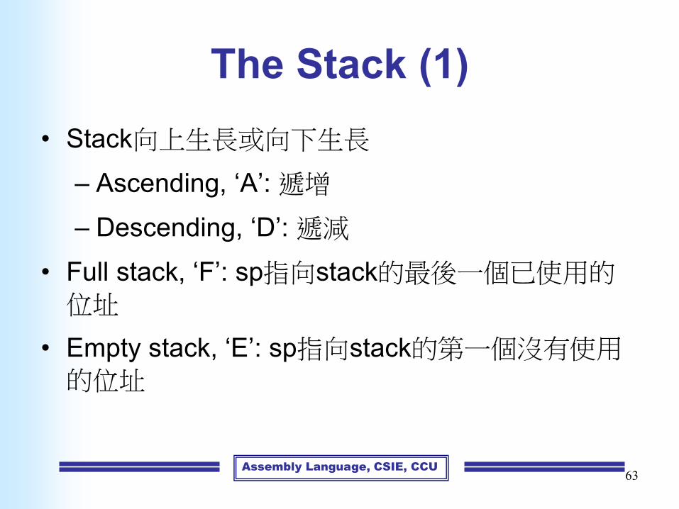
The Stack (1)
• Stack向上生長或向下生長
– Ascending, ‘A’: 遞增
– Descending, ‘D’: 遞減
• Full stack, ‘F’: sp指向stack的最後一個已使用的位址
• Empty stack, ‘E’: sp指向stack的第一個沒有使用的位址
Assembly Language, CSIE, CCU64
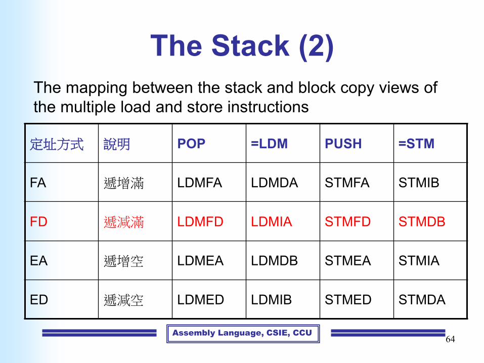
The Stack (2)
定址方式 說明 POP =LDM PUSH =STM
FA 遞增滿 LDMFA LDMDA STMFA STMIB
FD 遞減滿 LDMFD LDMIA STMFD STMDB
EA 遞增空 LDMEA LDMDB STMEA STMIA
ED 遞減空 LDMED LDMIB STMED STMDA
The mapping between the stack and block copy views of
the multiple load and store instructions

Assembly Language, CSIE, CCU
The Stack (3)
• The stack type to be used is given by the postfix to the
instruction:
– STMFD/LDMFD: Full Descending stack
– STMFA/LDMFA: Full Ascending stack
– STMED/LDMED: Empty Descending stack
– STMEA/LDMEA: Empty Ascending stack
• Pseudo instruction
• Note: ARM Compilers will always use a Full descending
stack
65

Assembly Language, CSIE, CCU66
code
static data
heap
stack
unused
application load address
top of application
top of heap
top of memory
stack pointer (sp)
stack limit (sl)
stack low-water mark
Stack 成長方向
High address
Low address
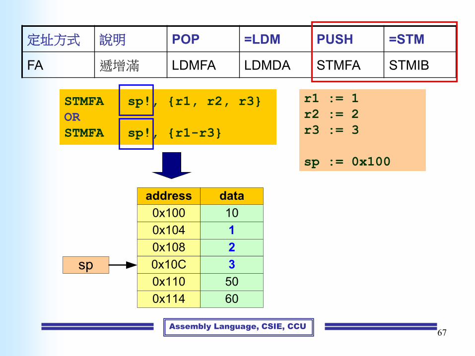
Assembly Language, CSIE, CCU
定址方式 說明 POP =LDM PUSH =STM
FA 遞增滿 LDMFA LDMDA STMFA STMIB
67
0x100
0x104
0x108
0x10C
0x110
0x114
10
1
2
3
50
60
address data
sp
STMFA sp!, {r1, r2, r3}
OR
STMFA sp!, {r1-r3}
r1 := 1
r2 := 2
r3 := 3
sp := 0x100

Assembly Language, CSIE, CCU
定址方式 說明 POP =LDM PUSH =STM
FA 遞增滿 LDMFA LDMDA STMFA STMIB
68
0x100
0x104
0x108
0x10C
0x110
0x114
10
1
2
3
50
60
address data
sp
LDMFA sp!, {r4, r5, r6}
OR
LDMFA sp!, {r4-r6}
r4 := 1
r5 := 2
r6 := 3
sp := 0x100
sp := 0x10C

Assembly Language, CSIE, CCU69
Single Register Swap
Instructions (1)• Allow a value in a register to be exchanged with a value
in memory
• Effectively do both a load and a store operation in one instruction
• They are little used in user-level programs
• Atomic operation
– 在操作期間,禁止其他指令對欲存取的儲存單元讀寫
• Application
– Implement semaphores (multi-threaded / multi-processor environment)

Assembly Language, CSIE, CCU70
Single Register Swap
Instructions (2)
SWP WORD exchange
tmp = mem32[Rn]
mem32[Rn] = Rm
Rd = tmp
SWPB Byte exchange
tmp = mem8[Rn]
mem8[Rn] = Rm
Rd = tmp
SWP{B} Rd, Rm, [Rn]
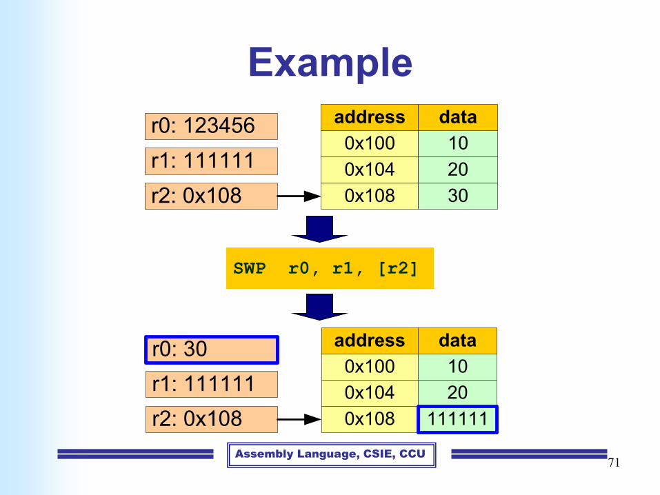
Assembly Language, CSIE, CCU71
Example
SWP r0, r1, [r2]
0x100
0x104
0x108
10
20
30
address data
r2: 0x108
r1: 111111
r0: 123456
0x100
0x104
0x108
10
20
111111
address data
r2: 0x108
r1: 111111
r0: 30

Assembly Language, CSIE, CCU72
Load an Address into
Register (1)• The ADR (load address into register) instruction
to load a register with a 32-bit address
• Example
– ADR r0,table
– Load the contents of register r0 with the 32-bit
address "table"Memory
table0x100
r0
Assembly Language, CSIE, CCU73
Load an Address into
Register (2)• ADR is a pseudo instruction
• Assembler will transfer pseudo instruction into a
sequence of appropriate normal instructions
• Assembler will transfer ADR into a single ADD,
or SUB instruction to load the address into a
register.

Assembly Language, CSIE, CCU74

Assembly Language, CSIE, CCU75
Outline
• Data processing instructions
• Data transfer instructions
• Control flow instructions
• Writing simple assembly language
programs

Assembly Language, CSIE, CCU76
Control Flow Instructions
• Determine which instructions get executed next
B LABEL
…
…
LABEL: …
MOV r0, #0 ; initialize counter
LOOP: ...
;do something here
...
ADD r0, r0, #1 ; increment loop counter
CMP r0, #10 ; compare with limit
BNE LOOP ; repeat if not equal
… ; else fall through

Assembly Language, CSIE, CCU77
Branch ConditionsBranch Interpretat i o n No rmal us es
B
BAL
Unconditional
Always
Always take this branch
Always take this branch
BEQ Equal Comparison equal or zero result
BNE Not equal Comparison not equal or non-zero result
BPL Plus Result positive or zero
BMI Minus Result minus or negative
BCC
BLO
Carry clear
Lower
Arithmetic operation did not give carry-out
Unsigned comparison gave lower
BCS
BHS
Carry set
Higher or same
Arithmetic operation gave carry-out
Unsigned comparison gave higher or same
BVC Overflow clear Signed integer operation; no overflow occurred
BVS Overflow set Signed integer operation; overflow occurred
BGT Greater than Signed integer comparison gave greater than
BGE Greater or equal Signed integer comparison gave greater or equal
BLT Less than Signed integer comparison gave less than
BLE Less or equal Signed integer comparison gave less than or equal
BHI Higher Unsigned comparison gave higher
BLS Lower or same Unsigned comparison gave lower or same
Conditional
execution

Assembly Language, CSIE, CCU78
Branch Instructions
B 跳躍 PC=label
BL 帶返回的跳躍 PC=label
LR=BL後面的第一道指令的位址
BX 跳躍並切換狀態 PC=Rm & 0xfffffffe, T=Rm & 1
BLX 帶返回的跳躍並切換狀態
PC=label, T=1
PC=Rm & 0xfffffffe, T=Rm & 1
LR = BLX後面的第一道指令的位址

Assembly Language, CSIE, CCU79
Branch and Link Instructions (1)
• BL instruction save the return address into r14 (lr)
BL subroutine ; branch to subroutine
CMP r1, #5 ; return to here
MOVEQ r1, #0
…
Subroutine: ; subroutine entry point
…
MOV pc, lr ; return
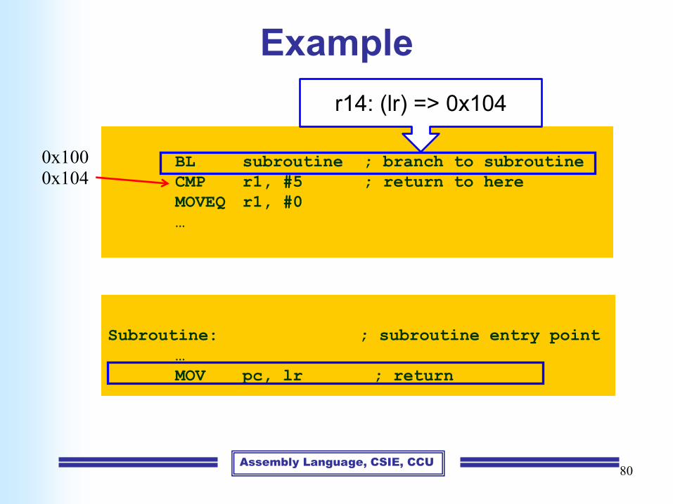
Assembly Language, CSIE, CCU80
Example
BL subroutine ; branch to subroutine
CMP r1, #5 ; return to here
MOVEQ r1, #0
…
Subroutine: ; subroutine entry point
…
MOV pc, lr ; return
0x1000x104
r14: (lr) => 0x104

Assembly Language, CSIE, CCU81
Example
BL subroutine ; branch to subroutine
CMP r1, #5 ; return to here
MOVEQ r1, #0
…
subroutine ; subroutine entry point
…
MOV pc, lr ; return
0x1000x104
r15 (pc) => 0x104

Assembly Language, CSIE, CCU82
Example
BL subroutine ; branch to subroutine
CMP r1, #5 ; return to here
MOVEQ r1, #0
…
Subroutine: ; subroutine entry point
…
MOV pc, lr ; return
0x1000x104

Assembly Language, CSIE, CCU83
Branch and Link Instructions (2)
• Problem
– If a subroutine wants to call another
subroutine, the original return address, r14,
will be overwritten by the second BL
instruction

Assembly Language, CSIE, CCU
Problem
84
BL SUB1 ; branch to subroutine SUB1
SUB r1, r2, #100
SUB1:
MOV r0, r1
BL SUB2
ADD r1, r2, r3
MOV pc, r14 ; copy r14 into r15 to return
SUB2:
…
MOV pc, r14 ; copy r14 into r15 to return
0x104
r14 = 0x80
0x80

Assembly Language, CSIE, CCU
Problem
85
BL SUB1 ; branch to subroutine SUB1
SUB r1, r2, #100
SUB1:
MOV r0, r1
BL SUB2
ADD r1, r2, r3
MOV pc, r14 ; copy r14 into r15 to return
SUB2:
…
MOV pc, r14 ; copy r14 into r15 to return
0x104
r14 = 0x104
0x80
Assembly Language, CSIE, CCU
Branch and Link Instructions (2)
• Solution
– Push r14 into a runtime stack
– The subroutine will often require some work
registers, the old values in these registers can
be saved at the same time using a store
multiple instruction
86

Assembly Language, CSIE, CCU87
Branch and Link Instructions (3)
BL SUB1 ; branch to subroutine SUB1
…
SUB1:
STMFD r13!, {r0-r2,r14} ; save work & link register
BL SUB2
…
LDMFD r13!, {r0-r2, pc} ; restore work register and
; return
SUB2:
…
MOV pc, r14 ; copy r14 into r15 to return

Assembly Language, CSIE, CCU88
Conditional Execution (1)
• One of the ARM's most interesting features is that each
instruction is conditionally executed
• In order to indicate the ARM's conditional mode to the
assembler, all you have to do is to append the
appropriate condition to a mnemonic
CMP r0, #5
BEQ BYPASS
ADD r1, r1, r0
SUB r1, r1, r2
BYPASS:
…
CMP r0, #5
ADDNE r1, r1, r0
SUBNE r1, r1, r2
…

Assembly Language, CSIE, CCU89
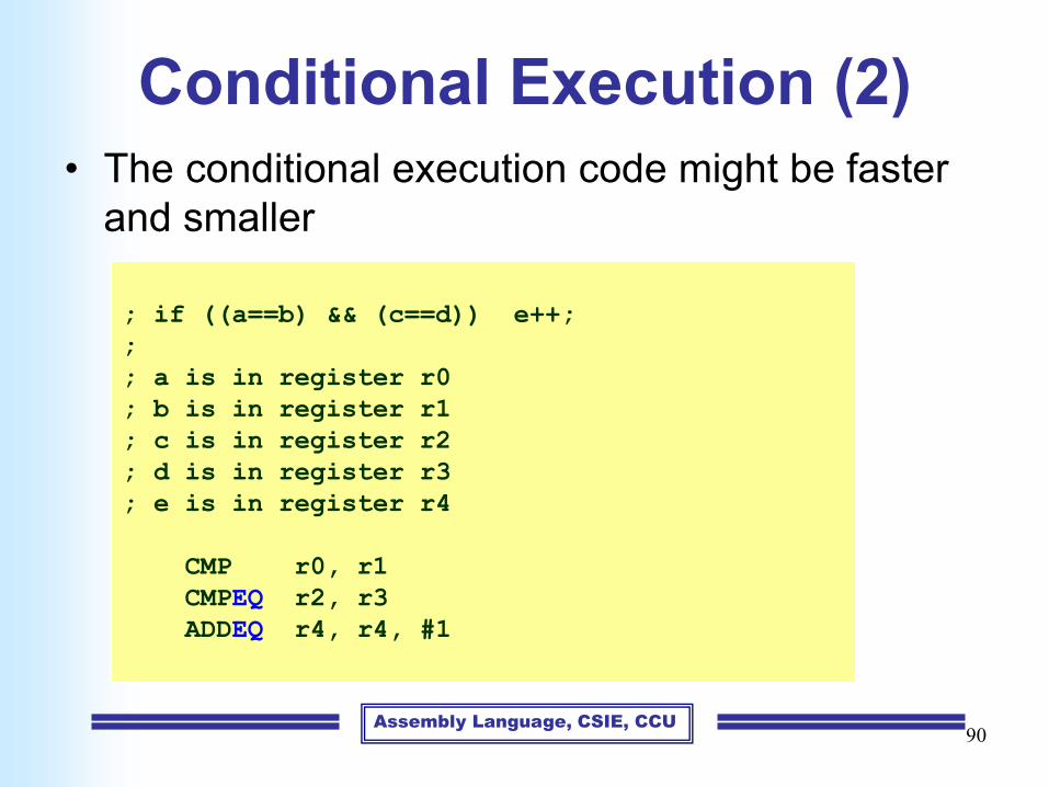
Conditional Execution (2)• The conditional execution code might be faster
and smaller
; if ((a==b) && (c==d)) e++;
;
; a is in register r0
; b is in register r1
; c is in register r2
; d is in register r3
; e is in register r4
CMP r0, r1
BNE LABEL1
CMP r2, r3
BNE LABEL1
ADD r4, r4, #1
LABEL1:
Assembly Language, CSIE, CCU90
Conditional Execution (2)
• The conditional execution code might be faster
and smaller
; if ((a==b) && (c==d)) e++;
;
; a is in register r0
; b is in register r1
; c is in register r2
; d is in register r3
; e is in register r4
CMP r0, r1
CMPEQ r2, r3
ADDEQ r4, r4, #1
Assembly Language, CSIE, CCU91
Conditional Execution (3)
• Predicate
• Real products
– Partial prediction support
• SPARC, Alpha, ELF
– Full prediction support
• IA-64, XScale, TIC6, ARM

Assembly Language, CSIE, CCU92
Conditional Execution (4)
if (r1) // there is a branch b
add r2, r3, r4;
else
add r2, r2, 1;
sub r5, r2, r6; // instruction that behind
// branch b
cmp.ne p0, p1, r1, 0; // branch b: set predicate register
add r2, r3, r4 (p0); // if p0 is true, r2 = r3 + r4
add r2, r2, 1 (p1); // if p1 is true, r2 = r2 + 1;
sub r5, r2, r6;
An example of IA64

Assembly Language, CSIE, CCU
64-bit ARM ISA
• The A64 instruction set does not include the
concept of predicated or conditional execution.
• Benchmarking shows that modern branch
predictors work well enough that predicated
execution of instructions does not offer sufficient
benefit to justify its significant use of opcode
space, and its implementation cost in advanced
implementations.
93
From: https://www.arm.com

Assembly Language, CSIE, CCU94
Supervisor Calls (1)
• SWI: SoftWare Interrupt (or SVC)
• The supervisor calls are implemented in system software
– They are probably different from one ARM system to
another
– Most ARM systems implement a common subset of
calls in addition to any specific calls required by the
particular application
; This routine sends the character in the bottom
; byte of r0 to the use display device
SWI SWI_WriteC ; output r0[7:0]

Assembly Language, CSIE, CCU95
Supervisor Calls (2)
; This routine returns control from a user program
; back to the monitor program
SWI SWI_Exit ; return to monitor

Assembly Language, CSIE, CCU96
Jump Tables (1)• A programmer sometimes wants to call one of a set of
subroutines, the choice depending on a value computed
by the program
BL JUMPTAB
..
JUMPTAB:
CMP r0, #0
BEQ SUB0
CMP r0, #1
BEQ SUB1
CMP r0, #2
BEQ SUB2
..
Note: slow when the list is
long, and all subroutines
are equally frequent
Assembly Language, CSIE, CCU97
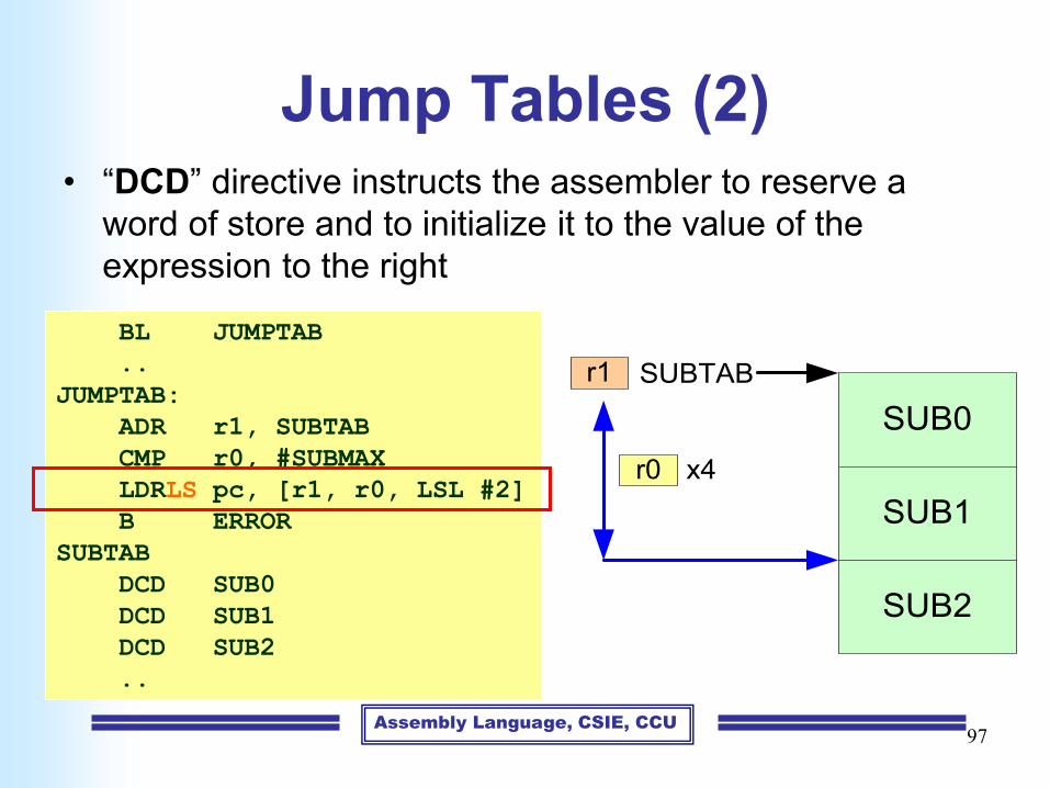
Jump Tables (2)• “DCD” directive instructs the assembler to reserve a
word of store and to initialize it to the value of the
expression to the right
BL JUMPTAB
..
JUMPTAB:
ADR r1, SUBTAB
CMP r0, #SUBMAX
LDRLS pc, [r1, r0, LSL #2]
B ERROR
SUBTAB
DCD SUB0
DCD SUB1
DCD SUB2
..
SUB0
SUBTABr1
SUB1
SUB2
r0 x4

Assembly Language, CSIE, CCU98
Outline
• Data processing instructions
• Data transfer instructions
• Control flow instructions
• Writing simple assembly language
programs
Assembly Language, CSIE, CCU99
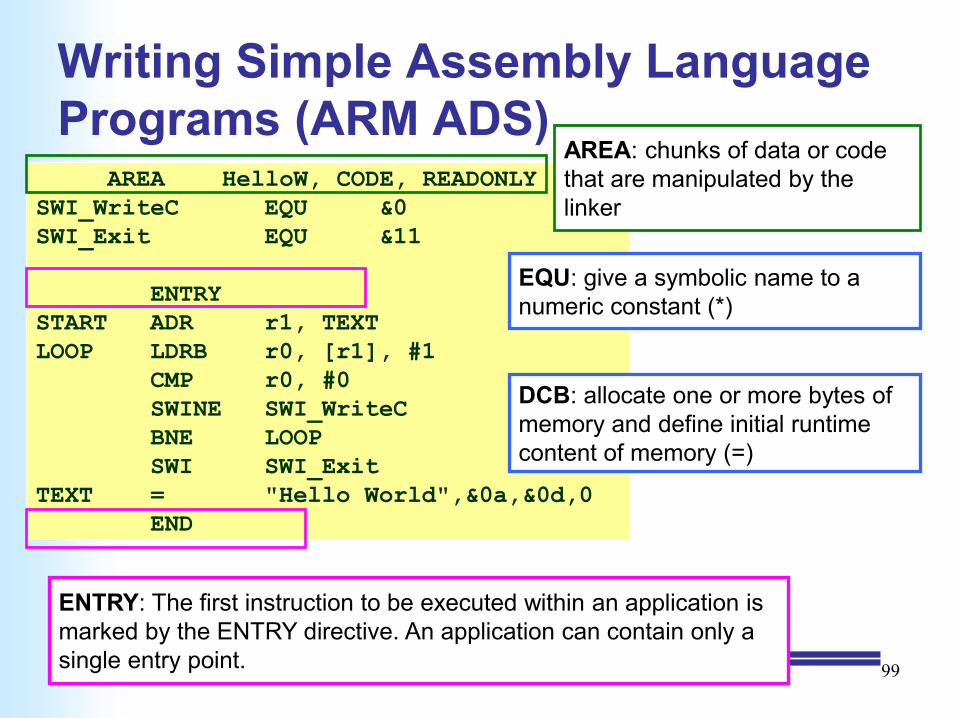
Writing Simple Assembly Language
Programs (ARM ADS)AREA HelloW, CODE, READONLY
SWI_WriteC EQU &0
SWI_Exit EQU &11
ENTRY
START ADR r1, TEXT
LOOP LDRB r0, [r1], #1
CMP r0, #0
SWINE SWI_WriteC
BNE LOOP
SWI SWI_Exit
TEXT = "Hello World",&0a,&0d,0
END
AREA: chunks of data or code
that are manipulated by the
linker
ENTRY: The first instruction to be executed within an application is
marked by the ENTRY directive. An application can contain only a
single entry point.
EQU: give a symbolic name to a
numeric constant (*)
DCB: allocate one or more bytes of
memory and define initial runtime
content of memory (=)

Assembly Language, CSIE, CCU100
General Assembly Form (ARM ADS)
• The three sections are separated by at least one whitespace character (a space or a tab)
• Actual instructions never start in the first column, since they must be preceded by whitespace, even if there is no label
• All three sections are optional
label <whitespace> instruction <whitespace> ;comment

Assembly Language, CSIE, CCU
Backup
101

Assembly Language, CSIE, CCU102
Operand 1
Result
ALU
Barrel Shifter
Operand 2
Using the Barrel Shifter:
The Second Operand
* Immediate value
• Register, optionally with shift
operation applied.
• Shift value can be either be:
– 5 bit unsigned integer
– Specified in bottom byte
of another register.

Assembly Language, CSIE, CCU103
Example: Pipelines (1)
• Laundry Example
• 4 load of clothes
– Washer takes 30 minutes
– Dryer takes 40 minutes
– “Folder” takes 20 minutes
A B C D

Assembly Language, CSIE, CCU104
Sequential Laundry
• Sequential laundry takes 6 hours for 4 loads
• If they learned pipelining, how long would laundry take?
A
B
C
D
30 40 20 30 40 20 30 40 20 30 40 20
6 PM 7 8 9 10 11 Midnight
Task
Order
Time

Assembly Language, CSIE, CCU105
Pipelined Laundry: Start work ASAP
• Pipelined laundry takes 3.5 hours for 4 loads
A
B
C
D
6 PM 7 8 9 10 11 Midnight
Task
Order
Time
30 40 40 40 40 20
Note:More time to do research laterOn that night for your advisor.

Assembly Language, CSIE, CCU106
Pipelined Design
• Prevalent in today’s processor
implementations
• More pipeline stage
– Improve throughput
– Help to increase clock frequency
IM Reg ALU DM Reg

Assembly Language, CSIE, CCU
Pipelines (1)
107

Assembly Language, CSIE, CCU108
Pipelines (2)
fetch dec reg ALU mem res1
fetch dec reg ALU mem res
fetch dec reg ALU mem res
2
3
time
instruction
• fetch: fetch the instruction from memory
• dec: decode it to see what sort of instruction it is
• reg: access any operands that may be required from the register bank
• ALU: combine the operands to form the result or a memory address
• mem: access memory for a data operand, if necessary
• res: write the result back to the register bank
Assembly Language, CSIE, CCU109
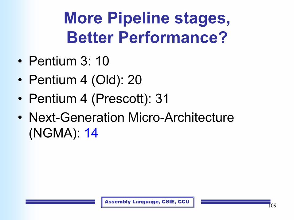
More Pipeline stages,
Better Performance?
• Pentium 3: 10
• Pentium 4 (Old): 20
• Pentium 4 (Prescott): 31
• Next-Generation Micro-Architecture
(NGMA): 14

Assembly Language, CSIE, CCU110
Pipelines Hazards
fetch dec reg ALU mem res1
fetch dec reg ALU mem res2
time
stall
instruction
Read-after-write pipeline hazard
Ex:
add r1, r2, #10 (write r1)
sub r3, r1, #20 (use r1)
Assembly Language, CSIE, CCU111
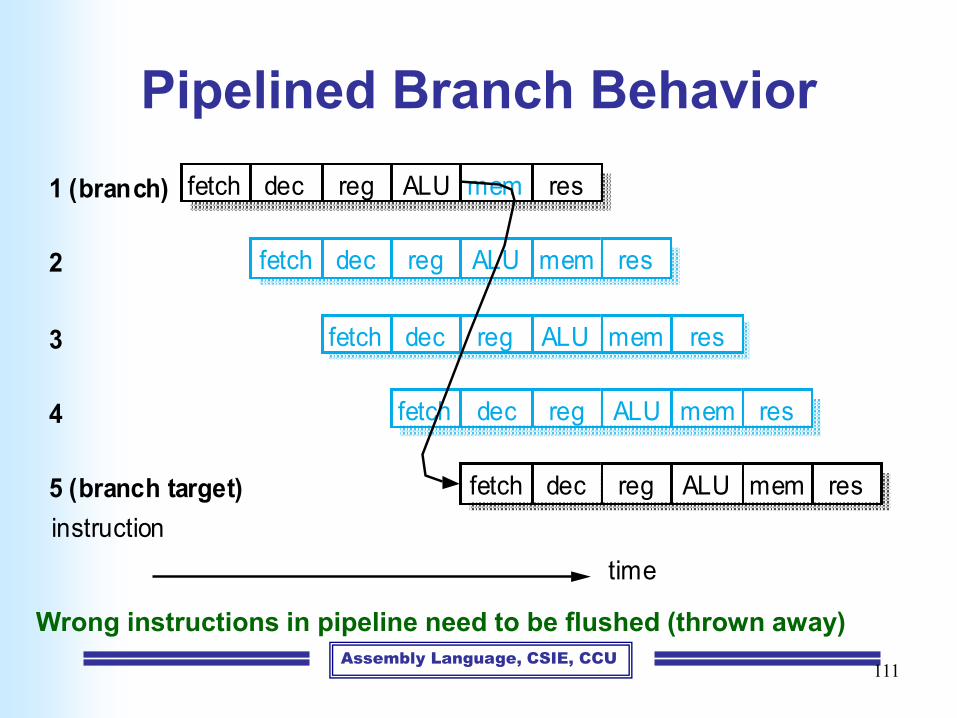
Pipelined Branch Behavior
fetch dec reg ALU mem res1 (branch)
fetch dec reg ALU mem res
fetch dec reg ALU mem res
2
3
time
instruction
fetch dec reg ALU mem res
fetch dec reg ALU mem res
4
5 (branch target)
Wrong instructions in pipeline need to be flushed (thrown away)

Assembly Language, CSIE, CCU112
Solutions
• Stall pipeline until branch resolved
• Branch prediction
– Mis-prediction will pay a big penalty
• Q: May we remove branch instruction?
– Conditional execution: operations based on
the value of a Boolean source operand
– drawback
• Affect instruction cache
• Increase the critical path length