ARM Assembly Programming -...
85
ARM Assembly Programming Cuauhtemoc Carbajal 06/08/2013
Transcript of ARM Assembly Programming -...

ARM Assembly Programming
Cuauhtemoc Carbajal06/08/2013

Introduction
• The ARM processor is very easy to program at the assembly level. (It is a RISC)
• We will learn ARM assembly programming at the user level.

Memory system
• Memory is a linear array of bytes addressed from 0 to 232-1
• Word, half-word, byte• Little-endian
00
10
20
30
FF
FF
FF
00
00
00
0x000000000x000000010x000000020x000000030x00000004
0x000000050x00000006
0xFFFFFFFF
0xFFFFFFFE0xFFFFFFFD
ARM programmer model
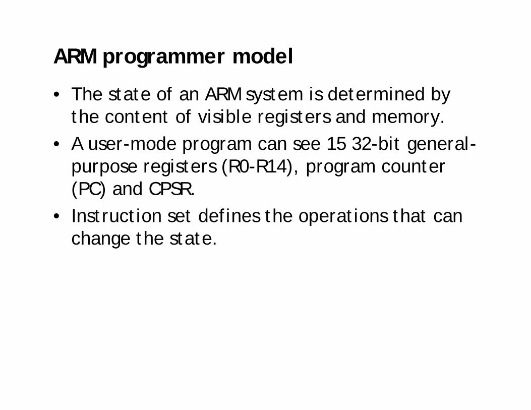
• The state of an ARM system is determined by the content of visible registers and memory.
• A user-mode program can see 15 32-bit general-purpose registers (R0-R14), program counter (PC) and CPSR.
• Instruction set defines the operations that can change the state.
Byte ordering
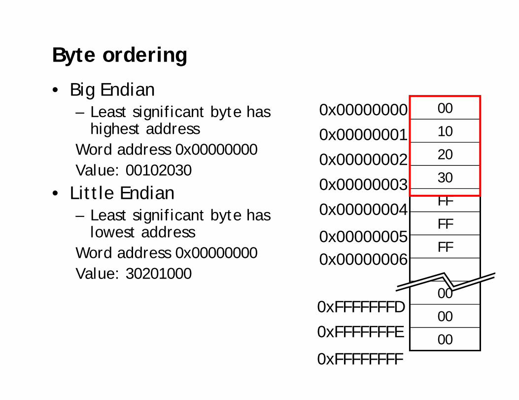
• Big Endian– Least significant byte has
highest addressWord address 0x00000000 Value: 00102030
• Little Endian– Least significant byte has
lowest addressWord address 0x00000000 Value: 30201000
00
10
20
30
FF
FF
FF
00
00
00
0x000000000x000000010x000000020x000000030x00000004
0x000000050x00000006
0xFFFFFFFF
0xFFFFFFFE0xFFFFFFFD

6
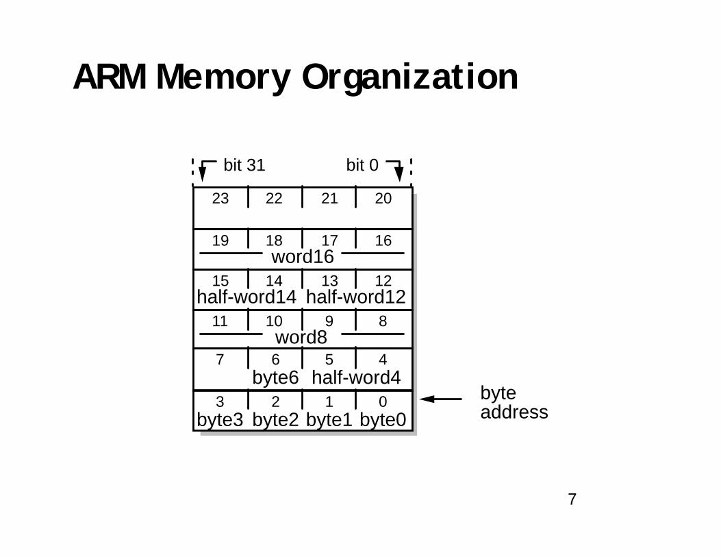
Data Sizes and Instruction Sets• The ARM is a 32-bit architecture
• When used in relation to the ARM:
– Byte means 8 bits
– Halfword means 16 bits (two bytes)
– Word means 32 bits (four bytes)
• Most ARM’s implement two instruction sets
– 32-bit ARM Instruction Set
– 16-bit Thumb Instruction Set
• Jazelle cores: execute Java bytecode in hardware
7
ARM Memory Organization
half-word4
word16
0123
4567
891011
byte0byte
12131415
16171819
20212223
byte1byte2
half-word14
byte3
byte6
address
bit 31 bit 0
half-word12
word8

8
Big Endian and Little EndianBig endian
Little endian

9
Processor Modes
• The ARM has seven basic operating modes:
– User : unprivileged mode under which most tasks run
– FIQ : entered when a high priority (fast) interrupt is raised
– IRQ : entered when a low priority (normal) interrupt is raised
– Supervisor : entered on reset and when a Software Interrupt instruction is executed
– Abort : used to handle memory access violations
– Undef : used to handle undefined instructions
– System : privileged mode using the same registers as user mode

10
ARM Registers (1)
r13_und r14_und r14_irq
r13_irq
SPSR_und
r14_abt r14_svc
user mode fiqmode
svcmode
abortmode
irqmode
undefinedmode
usable in user mode
privileged modes only
r13_abt r13_svc
r8_fiqr9_fiq
r10_fiqr11_fiq
SPSR_irq SPSR_abt SPSR_svc SPSR_fiqCPSR
r14_fiqr13_fiqr12_fiq
r0r1r2r3r4r5r6r7r8r9r10r11r12r13r14r15 (PC)
11
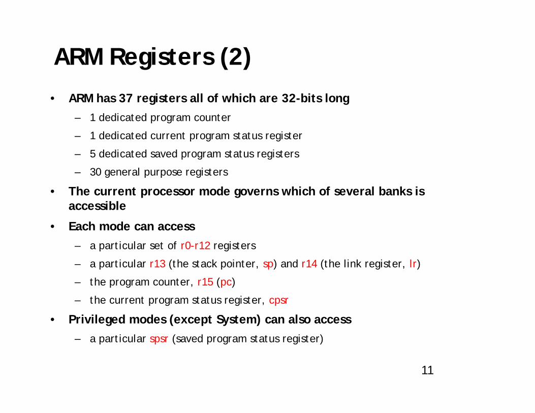
ARM Registers (2)• ARM has 37 registers all of which are 32-bits long
– 1 dedicated program counter
– 1 dedicated current program status register
– 5 dedicated saved program status registers
– 30 general purpose registers
• The current processor mode governs which of several banks is accessible
• Each mode can access– a particular set of r0-r12 registers
– a particular r13 (the stack pointer, sp) and r14 (the link register, lr)
– the program counter, r15 (pc)
– the current program status register, cpsr
• Privileged modes (except System) can also access– a particular spsr (saved program status register)

12
Current Program Status Registers (CPSR)
• Hold information about the most recently performed ALU operation• Control the enabling and disabling of interrupts• Set the processor operating mode

Current Program Status Registers (CPSR)
13

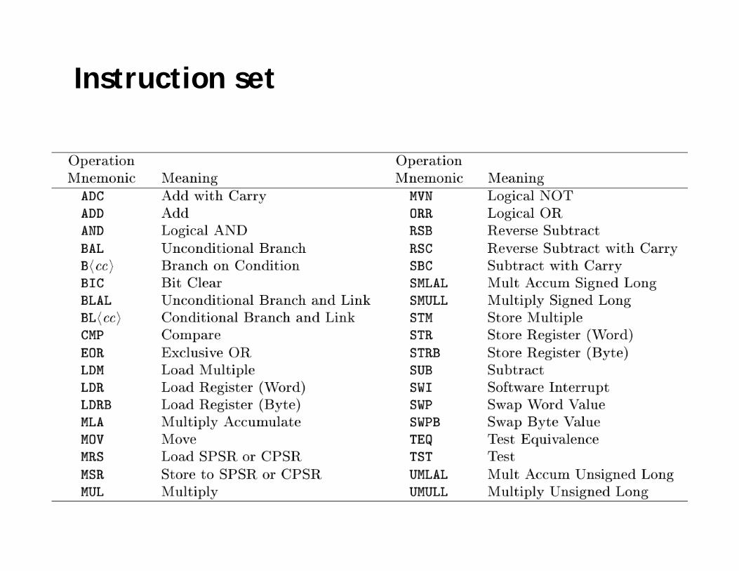
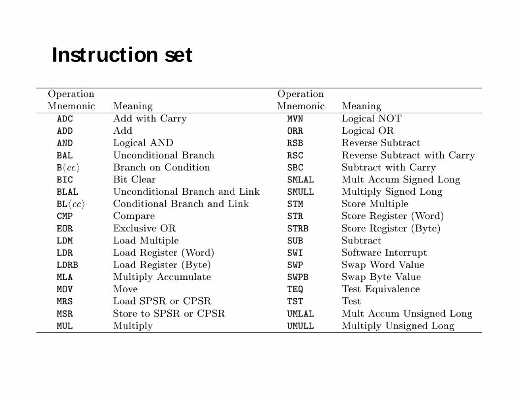
Instruction set
ARM instructions are all 32-bit long (except for Thumb mode). There are 232
possible machine instructions. Fortunately, they are structured.

Features of ARM instruction set
• Load-store architecture• 3-address instructions• Conditional execution of every instruction• Possible to load/store multiple register at once• Possible to combine shift and ALU operations in
a single instruction

Instruction set
MOV<cc><S> Rd, <operands>
MOVCS R0, R1 @ if carry is set@ then R0:=R1
MOVS R0, #0 @ R0:=0@ Z=1, N=0@ C, V unaffected

Instruction set
• Data processing (Arithmetic and Logical)• Data movement• Flow control

Data processing
• Arithmetic and logic operations• General rules:
– All operands are 32-bit, coming from registers or literals.
– The result, if any, is 32-bit and placed in a register (with the exception for long multiply which produces a 64-bit result)
– 3-address format

Arithmetic
• ADD R0, R1, R2 @ R0 = R1+R2• ADC R0, R1, R2 @ R0 = R1+R2+C• SUB R0, R1, R2 @ R0 = R1-R2• SBC R0, R1, R2 @ R0 = R1-R2+C-1• RSB R0, R1, R2 @ R0 = R2-R1• RSC R0, R1, R2 @ R0 = R2-R1+C-1

Bitwise logic
• AND R0, R1, R2 @ R0 = R1 and R2• ORR R0, R1, R2 @ R0 = R1 or R2• EOR R0, R1, R2 @ R0 = R1 xor R2• BIC R0, R1, R2 @ R0 = R1 and (~R2)
bit clear: R2 is a mask identifying which bits of R1 will be cleared to zero
R1=0x11111111 R2=0x01100101
BIC R0, R1, R2
R0=0x10011010

Register movement
• MOV R0, R2 @ R0 = R2• MVN R0, R2 @ R0 = ~R2
move negated
Comparison
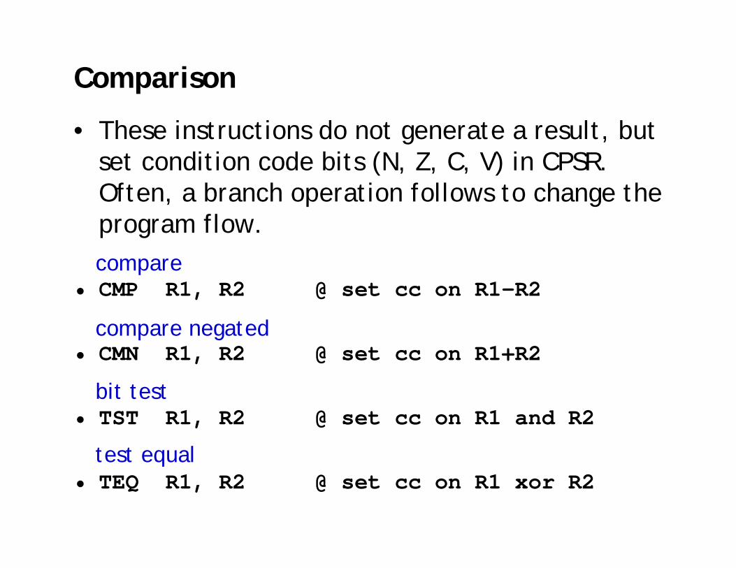
• These instructions do not generate a result, but set condition code bits (N, Z, C, V) in CPSR. Often, a branch operation follows to change the program flow.
• CMP R1, R2 @ set cc on R1-R2
• CMN R1, R2 @ set cc on R1+R2
• TST R1, R2 @ set cc on R1 and R2
• TEQ R1, R2 @ set cc on R1 xor R2
compare
compare negated
bit test
test equal

Addressing modes
• Register operandsADD R0, R1, R2
• Immediate operands
ADD R3, R3, #1 @ R3:=R3+1AND R8, R7, #0xff @ R8=R7[7:0]
a literal; most can be represented by (0..255)x22n 0<n<12
a hexadecimal literalThis is assembler dependent syntax.

Shifted register operands
• One operand to ALU is routed through the Barrel shifter. Thus, the operand can be modified before it is used. Useful for dealing with lists, table and other complex data structure. (similar to the displacement addressing mode in CISC.)

Logical shift left
MOV R0, R2, LSL #2 @ R0:=R2<<2@ R2 unchanged
Example: 0…0 0011 0000Before R2=0x00000030After R0=0x000000C0
R2=0x00000030
C 0register
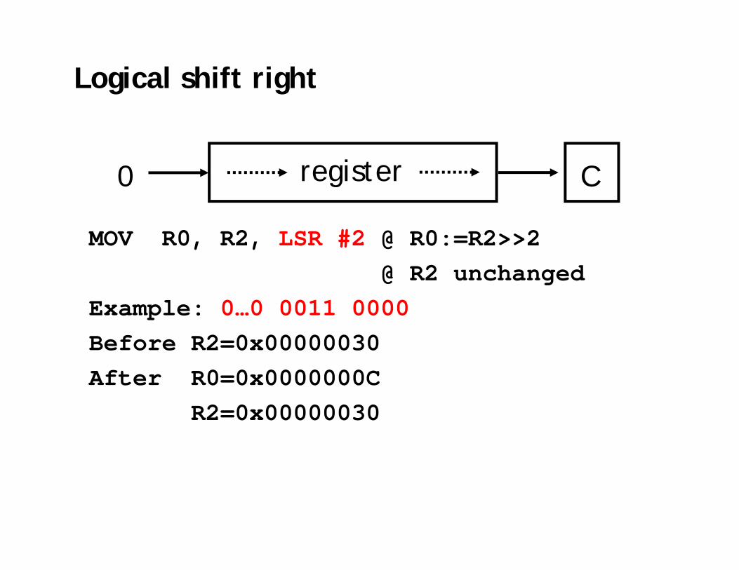
Logical shift right
MOV R0, R2, LSR #2 @ R0:=R2>>2@ R2 unchanged
Example: 0…0 0011 0000Before R2=0x00000030After R0=0x0000000C
R2=0x00000030
C0 register

Arithmetic shift right
MOV R0, R2, ASR #2 @ R0:=R2>>2@ R2 unchanged
Example: 1010 0…0 0011 0000Before R2=0xA0000030After R0=0xE800000C
R2=0xA0000030
MSB register C
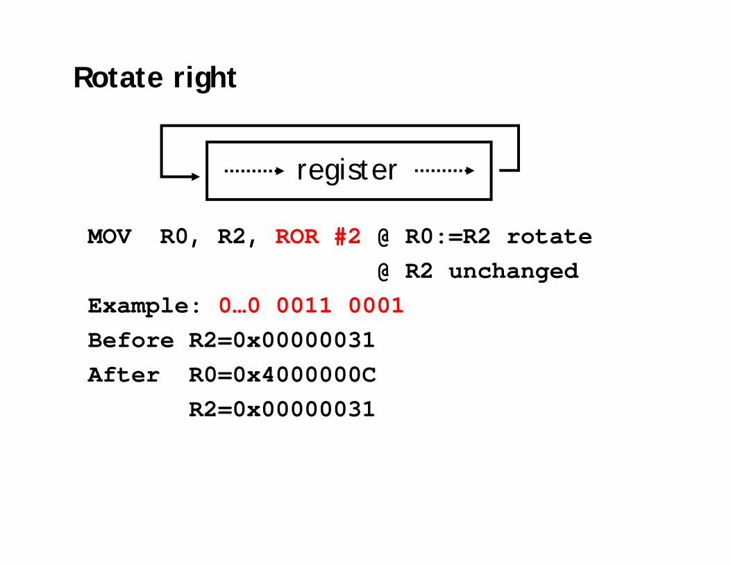
Rotate right
MOV R0, R2, ROR #2 @ R0:=R2 rotate@ R2 unchanged
Example: 0…0 0011 0001Before R2=0x00000031After R0=0x4000000C
R2=0x00000031
register
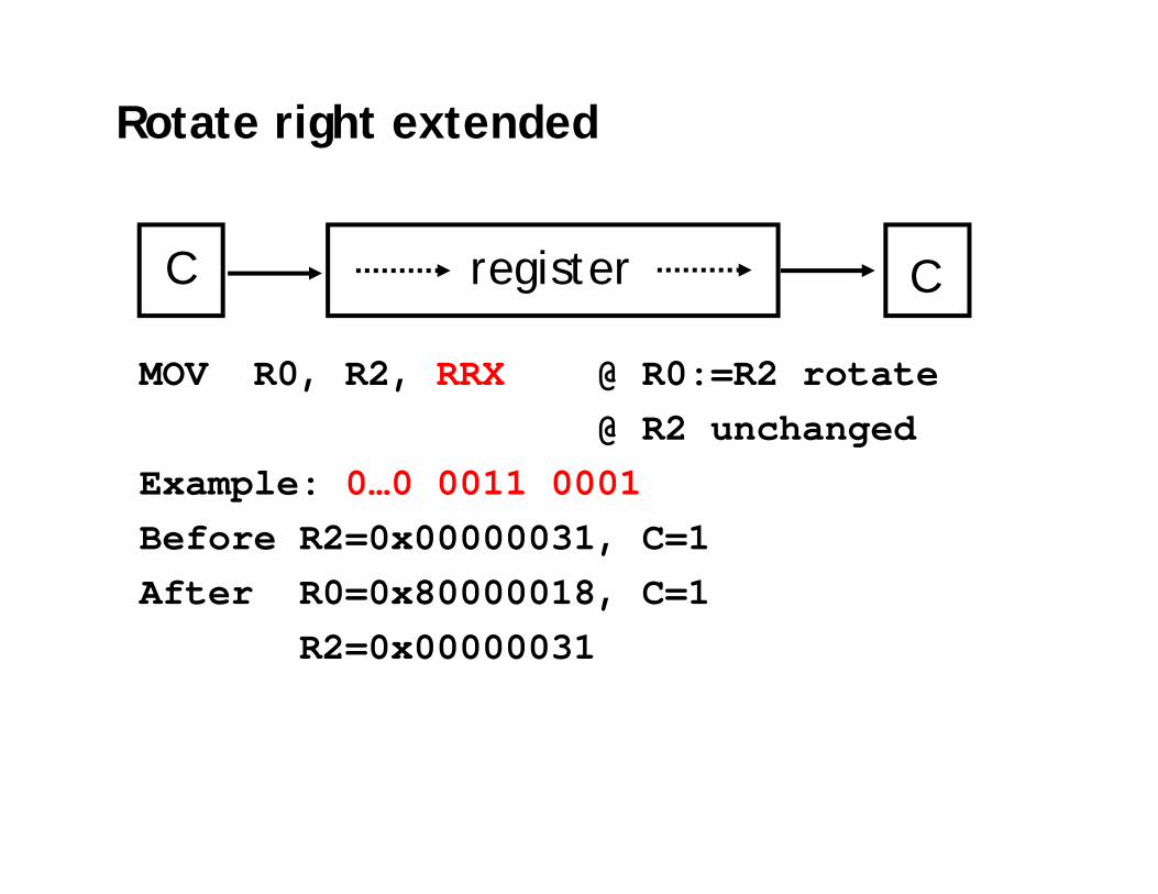
Rotate right extended
MOV R0, R2, RRX @ R0:=R2 rotate@ R2 unchanged
Example: 0…0 0011 0001Before R2=0x00000031, C=1After R0=0x80000018, C=1
R2=0x00000031
registerC C

Shifted register operands

Shifted register operands

Shifted register operands
• It is possible to use a register to specify the number of bits to be shifted; only the bottom 8 bits of the register are significant.
ADD R0, R1, R2, LSL R3 @ R0:=R1+R2*2R3

Setting the condition codes
• Any data processing instruction can set the condition codes if the programmers wish it to
64-bit addition
ADDS R2, R2, R0ADC R3, R3, R1
R1 R0
R3 R2
R3 R2
+
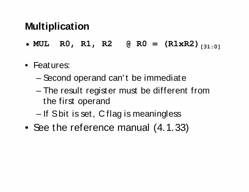
Multiplication
• MUL R0, R1, R2 @ R0 = (R1xR2)[31:0]
• Features:– Second operand can’t be immediate– The result register must be different from
the first operand– If S bit is set, C flag is meaningless
• See the reference manual (4.1.33)

Multiplication
• Multiply-accumulateMLA R4, R3, R2, R1 @ R4 = R3xR2+R1
• Multiply with a constant can often be more efficiently implemented using shifted register operand MOV R1, #35MUL R2, R0, R1
orADD R0, R0, R0, LSL #2 @ R0’=5xR0RSB R2, R0, R0, LSL #3 @ R2 =7xR0’

Data transfer instructions
• Move data between registers and memory• Three basic forms
– Single register load/store– Multiple register load/store– Single register swap: SWP(B), atomic
instruction for semaphore

Single register load/store
• The data items can be a 8-bitbyte, 16-bit half-word or 32-bit word.
LDR R0, [R1] @ R0 := mem32[R1]STR R0, [R1] @ mem32[R1] := R0
LDR, LDRH, LDRB for 32, 16, 8 bitsSTR, STRH, STRB for 32, 16, 8 bits

Load an address into a register
• The pseudo instruction ADR loads a register with an address
table: .word 10…
ADR R0, table
• Assembler transfer pseudo instruction into a sequence of appropriate instructions sub r0, pc, #12

Addressing modes
• Memory is addressed by a register and an offset.LDR R0, [R1] @ mem[R1]
• Three ways to specify offsets:– ConstantLDR R0, [R1, #4] @ mem[R1+4]
– RegisterLDR R0, [R1, R2] @ mem[R1+R2]
– Scaled @ mem[R1+4*R2]LDR R0, [R1, R2, LSL #2]
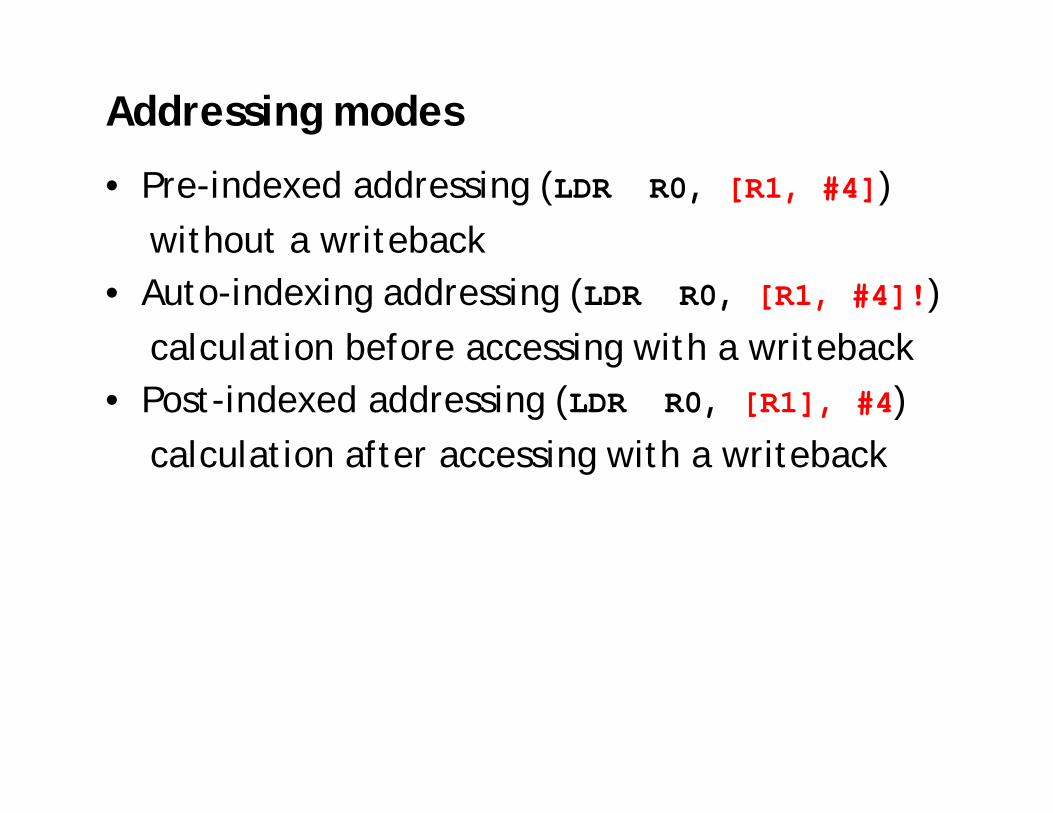
Addressing modes
• Pre-indexed addressing (LDR R0, [R1, #4])without a writeback
• Auto-indexing addressing (LDR R0, [R1, #4]!)calculation before accessing with a writeback
• Post-indexed addressing (LDR R0, [R1], #4)calculation after accessing with a writeback

Pre-indexed addressing
LDR R0, [R1, #4] @ R0=mem[R1+4]@ R1 unchanged
R0
R1 +
LDR R0, [R1, ]

Auto-indexing addressing
LDR R0, [R1, #4]! @ R0=mem[R1+4]@ R1=R1+4
LDR R0, [R1, ]!
R0
R1 +
No extra time; Fast;

Post-indexed addressing
LDR R0, R1, #4 @ R0=mem[R1]@ R1=R1+4
R0R1
+
LDR R0,[R1],
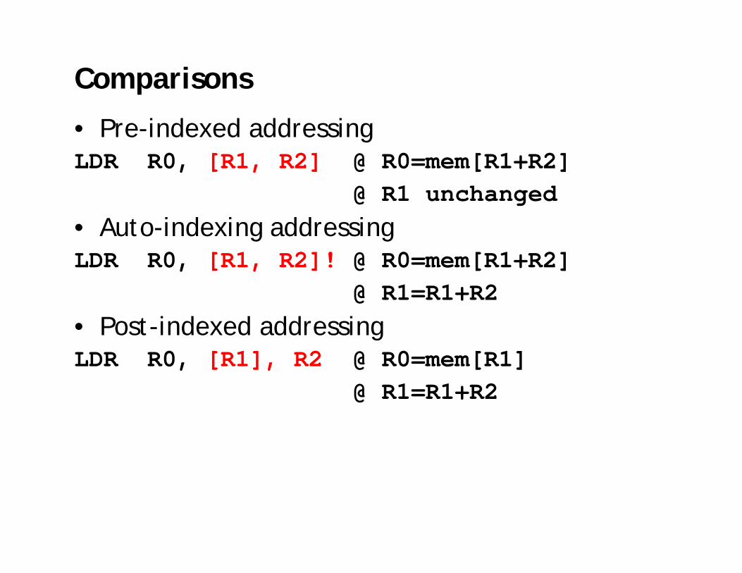
Comparisons
• Pre-indexed addressingLDR R0, [R1, R2] @ R0=mem[R1+R2]
@ R1 unchanged• Auto-indexing addressingLDR R0, [R1, R2]! @ R0=mem[R1+R2]
@ R1=R1+R2• Post-indexed addressingLDR R0, [R1], R2 @ R0=mem[R1]
@ R1=R1+R2

Application
ADR R1, tableloop: LDR R0, [R1]
ADD R1, R1, #4@ operations on R0…
ADR R1, tableloop: LDR R0, [R1], #4
@ operations on R0…
tableR1

Multiple register load/store
• Transfer large quantities of data more efficiently.
• Used for procedure entry and exit for saving and restoring workspace registers and the return address
registers are arranged an in increasing order; see manualLDMIA R1, {R0, R2, R5} @ R0 = mem[R1]
@ R2 = mem[r1+4]@ R5 = mem[r1+8]
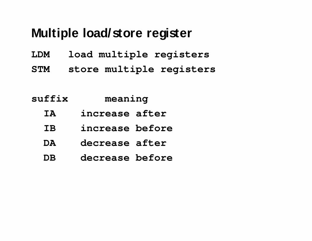
Multiple load/store register
LDM load multiple registersSTM store multiple registers
suffix meaningIA increase afterIB increase beforeDA decrease afterDB decrease before

Multiple load/store registerLDM<mode> Rn, {<registers>}IA: addr:=RnIB: addr:=Rn+4DA: addr:=Rn-#<registers>*4+4DB: addr:=Rn-#<registers>*4For each Ri in <registers>
IB: addr:=addr+4DB: addr:=addr-4Ri:=M[addr]IA: addr:=addr+4DA: addr:=addr-4
<!>: Rn:=addr
Rn R1
R2
R3

Multiple load/store registerLDM<mode> Rn, {<registers>}IA: addr:=RnIB: addr:=Rn+4DA: addr:=Rn-#<registers>*4+4DB: addr:=Rn-#<registers>*4For each Ri in <registers>
IB: addr:=addr+4DB: addr:=addr-4Ri:=M[addr]IA: addr:=addr+4DA: addr:=addr-4
<!>: Rn:=addr
Rn
R1
R2
R3

Multiple load/store registerLDM<mode> Rn, {<registers>}IA: addr:=RnIB: addr:=Rn+4DA: addr:=Rn-#<registers>*4+4DB: addr:=Rn-#<registers>*4For each Ri in <registers>
IB: addr:=addr+4DB: addr:=addr-4Ri:=M[addr]IA: addr:=addr+4DA: addr:=addr-4
<!>: Rn:=addr
Rn R3
R2
R1

Multiple load/store registerLDM<mode> Rn, {<registers>}IA: addr:=RnIB: addr:=Rn+4DA: addr:=Rn-#<registers>*4+4DB: addr:=Rn-#<registers>*4For each Ri in <registers>
IB: addr:=addr+4DB: addr:=addr-4Ri:=M[addr]IA: addr:=addr+4DA: addr:=addr-4
<!>: Rn:=addr
Rn
R1
R2
R3

Multiple load/store register
LDMIA R0, {R1,R2,R3}
orLDMIA R0, {R1-R3}
R1: 10R2: 20R3: 30R0: 0x10
addr data0x010 10
0x014 20
0x018 30
0x01C 40
0x020 50
0x024 60
R0

Multiple load/store register
LDMIA R0!, {R1,R2,R3}
R1: 10R2: 20R3: 30R0: 0x01C
addr data0x010 10
0x014 20
0x018 30
0x01C 40
0x020 50
0x024 60
R0

Multiple load/store register
LDMIB R0!, {R1,R2,R3}
R1: 20R2: 30R3: 40R0: 0x01C
addr data0x010 10
0x014 20
0x018 30
0x01C 40
0x020 50
0x024 60
R0

Multiple load/store register
LDMDA R0!, {R1,R2,R3}
R1: 40R2: 50R3: 60R0: 0x018
addr data0x010 10
0x014 20
0x018 30
0x01C 40
0x020 50
0x024 60
R0

Multiple load/store register
LDMDB R0!, {R1,R2,R3}
R1: 30R2: 40R3: 50R0: 0x018
addr data0x010 10
0x014 20
0x018 30
0x01C 40
0x020 50
0x024 60
R0

Application
• Copy a block of memory– R9: address of the source– R10: address of the destination– R11: end address of the source
loop: LDMIA R9!, {R0-R7}STMIA R10!, {R0-R7}CMP R9, R11BNE loop

Application
• Stack (full: pointing to the last used; ascending: grow towards increasing memory addresses)
LDMFD R13!, {R2-R9}… @ modify R2-R9STMFD R13!, {R2-R9}
mode POP =LDM PUSH =STM
Full ascending (FA) LDMFA LDMDA STMFA STMIB
Full descending (FD) LDMFD LDMIA STMFD STMDB
Empty ascending (EA) LDMEA LDMDB STMEA STMIA
Empty descending (ED) LDMED LDMIB STMED STMDA

Control flow instructions
• Determine the instruction to be executed next• Branch instruction
B label…
label: …
• Conditional branchesMOV R0, #0
loop: …ADD R0, R0, #1CMP R0, #10BNE loop

Branch conditions

Branch and link
• BL instruction save the return address to R14(lr)
BL sub @ call subCMP R1, #5 @ return to hereMOVEQ R1, #0…
sub: … @ sub entry point…MOV PC, LR @ return

Branch and link
BL sub1 @ call sub1…
sub1: STMFD R13!, {R0-R2,R14}BL sub2…LDMFD R13!, {R0-R2,PC}
sub2: ……MOV PC, LR
use stack to save/restore the return address and registers

Conditional execution
• Almost all ARM instructions have a condition field which allows it to be executed conditionally.
movcs R0, R1

Conditional execution
CMP R0, #5BEQ bypass @ if (R0!=5) {ADD R1, R1, R0 @ R1=R1+R0-R2 SUB R1, R1, R2 @ }
bypass: …
CMP R0, #5ADDNE R1, R1, R0SUBNE R1, R1, R2
Rule of thumb: if the conditional sequence is three instructionsor less, it is better to use conditional execution than a branch.
smaller and faster
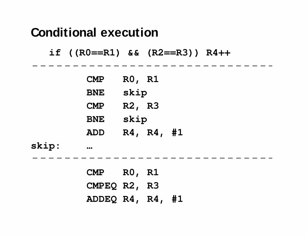
Conditional executionif ((R0==R1) && (R2==R3)) R4++
CMP R0, R1BNE skipCMP R2, R3BNE skipADD R4, R4, #1
skip: …
CMP R0, R1CMPEQ R2, R3ADDEQ R4, R4, #1
Instruction set

ARM assembly program
main:LDR R1, value @ load valueSTR R1, resultSWI #11
value: .word 0x0000C123result: .word 0
label operation operand comments
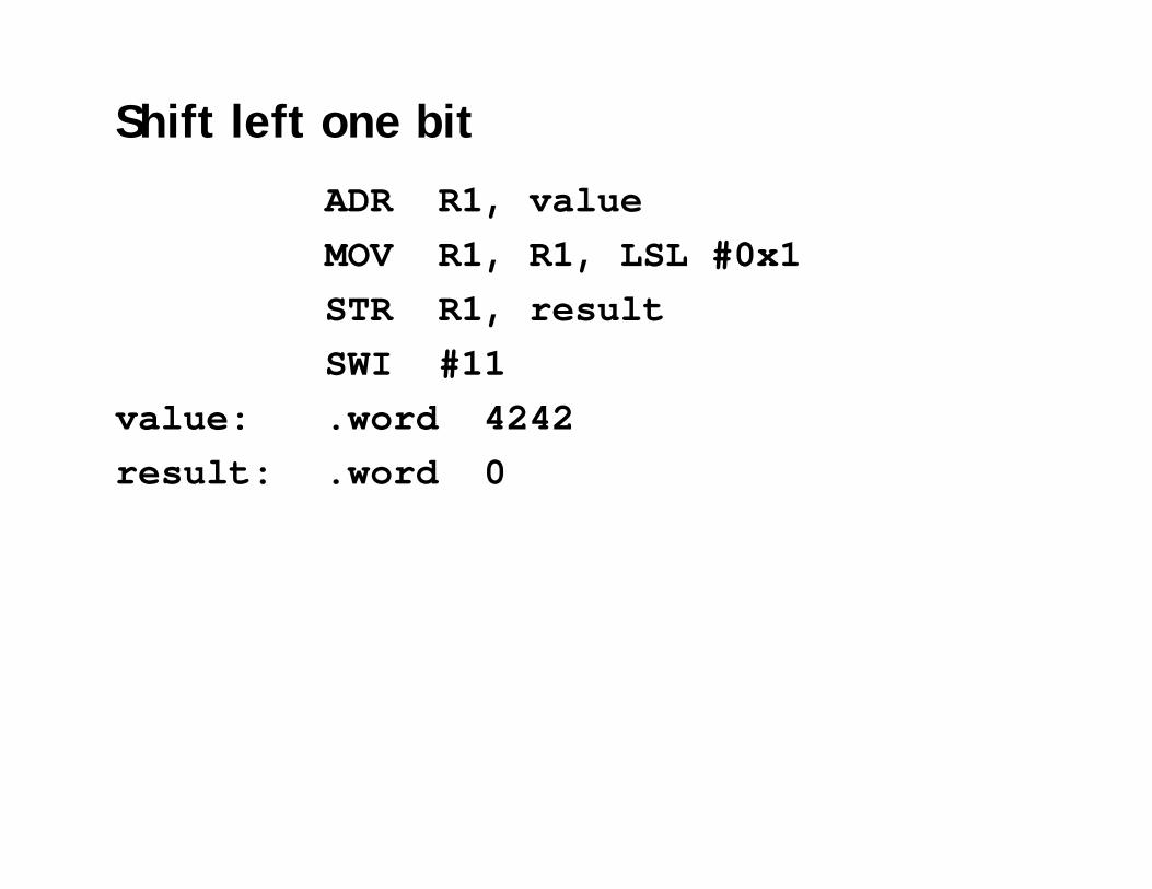
Shift left one bit
ADR R1, valueMOV R1, R1, LSL #0x1 STR R1, resultSWI #11
value: .word 4242result: .word 0

Add two numbers
main:ADR R1, value1ADR R2, value2ADD R1, R1, R2STR R1, resultSWI #11
value1: .word 0x00000001value2: .word 0x00000002result: .word 0

64-bit addition
ADR R0, value1LDR R1, [R0]LDR R2, [R0, #4]ADR R0, value2LDR R3, [R0]LDR R4, [R0, #4]ADDS R6, R2, R4ADC R5, R1, R3STR R5, [R0]STR R6, [R0, #4]SWI #11
value1: .word 0x00000001, 0xF0000000value2: .word 0x00000000, 0x10000000result: .word 0
01F0000000+ 00100000000200000000
R1 R2+ R3 R4R5 R6
C

Loops
• For loopsfor (i-0; i<10; i++) {a[i]=0;}
MOV R1, #0ADR R2, AMOV R0, #0
LOOP: CMP R0, #10BGE EXITSTR R1, [R2, R0, LSL #2]ADD R0, R0, #1B LOOP
EXIT: ..

Loops
• While loopsLOOP: … ; evaluate expression
BEQ EXIT… ; loop bodyB LOOP
EXIT: …

Find larger of two numbersADR R1, value1ADR R2, value2CMP R1, R2BHI Done MOV R1, R2
Done: STR R1, resultSWI #11
value1: .word 4value2: .word 9result: .word 0
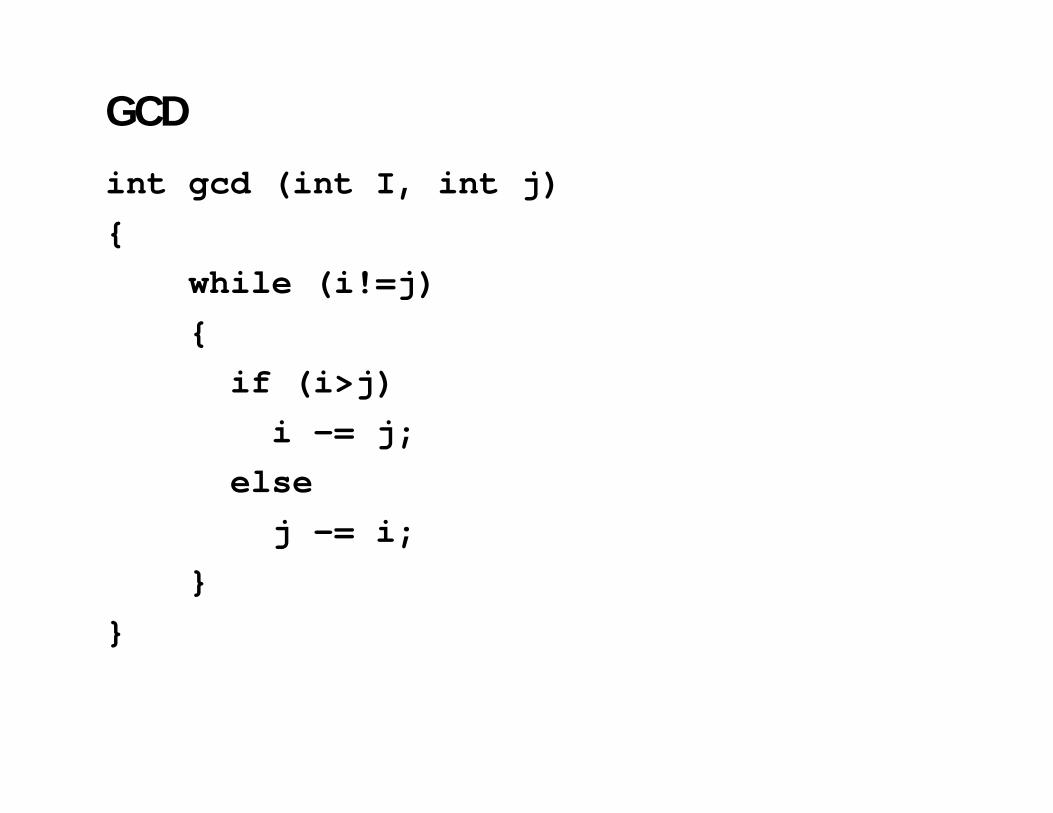
GCD
int gcd (int I, int j){
while (i!=j){
if (i>j)i -= j;
elsej -= i;
}}

GCD
Loop: CMP R1, R2SUBGT R1, R1, R2SUBLT R2, R2, R1BNE loop

Count negatives; count the number of negatives in; an array DATA of length LENGTH
ADR R0, DATA @ R0 addrEOR R1, R1, R1 @ R1 countLDR R2, Length @ R2 indexCMP R2, #0BEQ Done
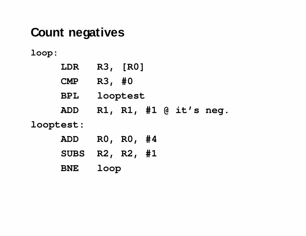
Count negativesloop:
LDR R3, [R0]CMP R3, #0BPL looptest ADD R1, R1, #1 @ it’s neg.
looptest:ADD R0, R0, #4SUBS R2, R2, #1BNE loop

Subroutines
• Passing parameters in registersAssume that we have three parameters BufferLen, BufferA, BufferB to pass into a subroutine
ADR R0, BufferLenADR R1, BufferAADR R2, BufferBBL Subr

Passing parameters using stacks
• Caller
MOV R0, #BufferLenSTR R0, [SP, #-4]!MOV R0, =BufferASTR R0, [SP, #-4]!MOV R0, =BufferBSTR R0, [SP, #-4]!BL Subr
BufferB
BufferA
BufferLen
SP

Passing parameters using stacks
• CalleeSubr STMDB SP, {R0,R1,R2,R13,R14}LDR R2, [SP, #0]LDR R1, [SP, #4]LDR R0, [SP, #8]…
LDMDB SP, {R0,R1,R2,R13,R14}MOV PC, LR
R0
R1
R2
R13
R14
BufferB
BufferA
BufferLen
SP

Passing parameters using stacks
• CalleeSubr STMDB SP, {R0,R1,R2,R13,R14}LDR R2, [SP, #0]LDR R1, [SP, #4]LDR R0, [SP, #8]…
LDMDB SP, {R0,R1,R2,R13,PC}
R0
R1
R2
R13
R14
BufferB
BufferA
BufferLen
SP

Review
• ARM architecture• ARM programmer model• ARM instruction set• ARM assembly programming

ARM programmer model
00
10
20
30
FF
FF
FF
00
00
00
0x000000000x000000010x000000020x000000030x00000004
0x000000050x00000006
0xFFFFFFFF
0xFFFFFFFE0xFFFFFFFD
R0 R1 R2 R3
R4 R5 R6 R7
R8 R9 R10 R11
R12 R13 R14 PC
Instruction set

References
• ARM Limited. ARM Architecture Reference Manual.
• Peter Knaggs and Stephen Welsh, ARM: Assembly Language Programming.
• Peter Cockerell, ARM Assembly Language Programming.