
The AAF Scientific Advisory Group was activated lateThe propellants studied included solid...
186
Transcript of The AAF Scientific Advisory Group was activated lateThe propellants studied included solid...


The AAF Scientific Advisory Group was activated late in 1944 by General of the Army H. H. Arnold. He secured the senices of Dr. Theodore von Karman, renowned scientist and consultant in aeronautics, who agreed to organize and direct the group.
Dr. von Karman gathered about him a group of American scientists from every field of research having a bearing on air power. These men then analyzed important developments in the basic sciences, both here and abroad, and attempted to evaluate the effects of their application to air power.
This volume is one of a group of reports made to the Army Air Forces by the Scientific Advisory Group.
1hIa doculllent contains IIIfannotlon affecting .... ftCIfIonal de*- of .... UnIted Statft wtthIft .... lIIeaning of .... Espionage Act. 50 U. S. C .. 31 and 32. al alMftded.1ta lraMriulan or .... revelation of Its -...... In any Il10_ to all UIIOutharized ~ Is pt'OhIblted by law.
AAF SCIENTIFIC ADVISORY GROUP
Dr. Th. von Karman
Director
Colonel F. E. Glantzberg
Deputy Director, Military Dr. H. L. Dryden
Deputy Director, Scientific
Lt Col G. T. McHugh, Executive
Capt C. H. Jackson, Jr., Secretary
CONSULTANTS
Dr. C. W. Bray
Dr. L. A. DuBridge
Dr. Pol Duwez
Dr. G. Gamow
Dr. I. A. Getting
Dr. 1. P. Hammett Dr. W. S. Hunter
Dr. I. P. Krick
Dr. D. P. MacDougall
Dr. G. A. Morton
Dr. N. M. Newmark
Dr. W. H. Pickering
Dr. E. M. Purcell
Dr. G. B. Schubauer
Dr. W. R. Sears
Dr. A. J. Stosick
Dr. W. J. Sweeney
Dr. H. S. Tsien
Dr. G. E. Valley
Dr. F. L. Wattendorf Dr. F. Zwicky
Dr. V. K. Zworykin
Colonel D. N. Yates
Colonel W. R. Lovelace II
Lt Col A. P. Gagge
Lt Col F. W. Williams
Major T. F. Walkowicz
Capt C. N. Hasert
Mr. M. Alperin Mr. I. L. Ashkenas
Mr. G. S. Schairer
LAYOUT & ILLUSTRATION
Capt M. Miller
Capt T. E. Daley
il

TABLE OF CONTENTS
Page
Part I - Recent Developments of Several Selected Fields in Germany and Switzerland
Rockets. .............................................................. 1
Arrow Wing. . . . . . . . . . . . . . . . . . . . . . . . . . . . . . . . . . . . . . . . . . . . . . . . . . . . . . . . . . . 7
Ramjet.. . . ............................................................ 22
Aeropulse ...................................... ' .......... '.' . . . . . . . . . . . 25
Installation of Turbojets in an Airplane. . .. . . ........................... 27
Gasdynamics with Supersonic Velocities................................. 30
Boundary Layers and the Interaction of Boundary Layers and Shock Waves in Transonic Flows. . ........................................ 34
Liquid Explosive Bombs. .............................................. 38
Part II - Historical Notes on German Guided Missile Development. . . . . . . . . . . . . . . . . . . . . . . . . . . . . . . 47 to 71
Part III - Reports on Selected Topics of German and Swiss Aeronautical Developments
German Developments in Gas Turbine Propulsion....................... 75
Research on Gas Turbine Propulsion at the LFA. . . . ..................... 83
The LFA Free Piston Engine. . . ......................................... 85
Test Facilities at the AVA, Gottingen.................................... 87
Axial Compressor Development at the AVA, GOttingen. . . . . . . . . . . . . . . . . . . 89
Flow Measurement Technique. . . . . . . . . . . . . . . . . . . . . . . . . . . . . • . . . . . . . . . . . . 92
German Wind Tunnels. . . . . . . . . . . . . . . . . . . . . . . . . . . . . . . . . . . . . . . . . . . . . . . . . 96
Kochel Supersonic Wind Tunnels ....................................... 103
Oual Wind Tunnel. . . . . . . . . . .. . . . . . . .. .. . . .. . . . . .. . . . . . . . . . . . . . . . . . . .. 105
The 2.8 Meter High Speed Wind Tunnel of the Hermann Goring Luftfahrtforschungsanstalt, Braunschweiz........................... 107
References. . . . . . . . . . . . . . . . . . . . . . . . . . . . . . . . . . . . . . . . . . . . . . . . . . . . . . . . . . . .. 113
Conference at Brown Boveri, Baden, Switzerland. . . . . . . . . . . . . . . . . . . . . . . .. 114
Appendices .............................•..........•.................•.. 118
Part IV - japan's Aeronautic Research Program and Achievements .............................. 151 to 162
Part V - Remarks on the Japanese War Technical Effort .. 165 to 168
Part VI - A Brief Survey of German Electronic Developments .............................. 171 to 177
iii


PART I
RECENT DEVELOPMENTS OF SEVERAL SELECTED FIELDS OF AERONAUTICS IN GERMANY
AND SWITZERLAND
By
H. S. TSIEN
The following is a series of brief reports on the recent aeronautical developments of several selected fields in Germany and Switzerland, obtained during the overseas mission of the AAF Scientific Advisory Group during May and June of 1945. It is meant to give a coherent picture of the facts with little discussion on their relative importance, as such discussion can only have meaning after the completion of the over-all survey and the comparison of technical development made in this country and other countries.


RESTRICTED
PART I
RECENT DEVELOPMENTS OF SEVERAL SELECTED FIELDS OF AERONAUTICS IN GERMANY
AND SWITZERLAND
ROCKETS
INTRODUCTION
The intensive development of rockets in Germany started approximately in 1936 when the preparation for war was pursued in earnest. The main applications planned were:
(a) Main propulsion power plant for pursuit and fighter airplanes with high rate of climb and high horizontal speed at very high altitudes.
(b) Auxiliary power plant for assisted take-off to shorten ground run, for increasing the rate of climb, and for braking during landing on small fields.
(c) Propulsion for munitions such as antiaircraft rockets, glide bombs, accelerated bombs, and projectiles.
(d) Propulsion for torpedoes and braking the torpedoes launched by fast aircraft before entering water.
(e) Gas generation by rocket propellants for rotating or translational drive.
To develop the rockets for such purposes, the German industries and research institutions were mobilized. The most active ones were the following:
(a) Luftfahrtforschungsanstalt Hermann Goring, Braunschweig. Small research installation at Volkenrode (Noeggareth and Edse), and large installation at Fassburg. (A. Busemann, director, Grumbt in charge, also Winkler.)
(b) Luftfahrtforschungsanstalt Munchen. Planned extensive installation at Otto-brunn. (0. Lutz, director.)
(c) Heeresanstalt, Peenemunde.
(d) Rheinmetall.Borsig, A. G., Berlin· Marienfelde (solid propellants).
(e) Fa. Wilhelm Schmidding, A. G. Bodenbach (liquid propellants).
(f) H. Walter, K. G., Kiel (hydrogen-peroxide propellants).
1
The propellants studied included solid propellants, solid-liquid propellants, and liquid propellants. The solid-liquid propellant rockets are rockets with one component. of the propellant as solid and stored in the motor chamber, while the liquid component· is injected and reaction takes place in the chamber. This is a type not known previously and may be worth detailed consideration.
SOLID PROPELLENT ROCKETS
The propellant used in the German artillery rockets is a mixture of nitrocellulose and diglycol dinitrate with a few minor constituents. (See Appendix 1.) The propellant is mixed without solvent and is thus called POL Pulver (Pulver ohne Losungsmittel). The grains were obtained by pressing. The manufacturers of this type of powder were:
(a) Dynamit, A. G., Hamburg.
(b) Westphalische - Anhalt Sprengstoff, A. G., Wittenberg (Elbe).
(c) Wolff, A. G., Walrode (North of Hanover).
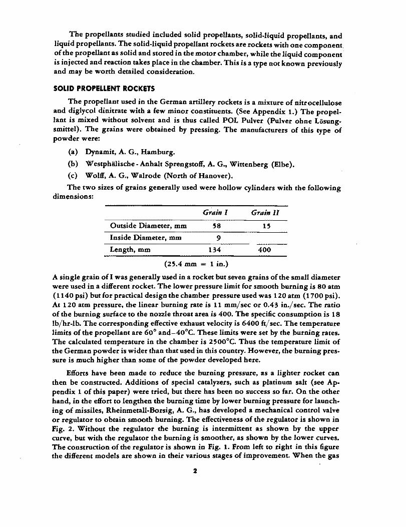
The two sizes of grains generally used were hollow cylinders with the following dimensions:
Grain 1 Grain 11
Outside Diameter, mm 58 15
Inside Diameter, mm 9
Length, mm 134 400
(25.4 mm = 1 in.)
A single grain of I was generally used in a rocket but seven grains of the small diameter were used in a different rocket. The lower pressure limit for smooth burning is 80 atm (1140 psi) butfor practical design the chamber pressure used was 120 atm (1700 psi). At 120 atm pressure, the linear burning rate is 11 mm/sec or 0.43 in./sec. The ratio of the burning surface to the nozzle throat area is 400. The specific consumption is 18 lb/hr-Ib. The corresponding effective exhaust velocity is 6400 ft/ sec. The temperature limits of the propellant are 60° and-40°C. These limits were set by the burning rates. The calculated temperature in the chamber is 2500°C. Thus the temperature limit of the German powder is wider than that used in this country. However, the burning pressure is much higher than some of the powder developed here.
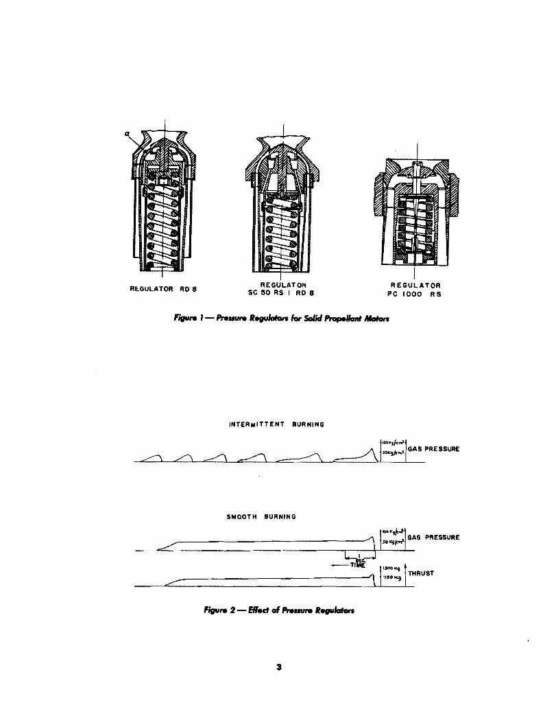
Efforts have been made to reduce the burning pressure, as a lighter rocket can then be constructed. Additions of special catalyzers, such as platinum salt (see Appendix 1 of this paper) were tried, but there has been no success so far. On the other hand, in the effort to lengthen the burning time by lower burning pressure for launching of missiles, Rheinmetall-Borsig, A. G., has developed a mechanical control valve or regulator to obtain smooth burning. The effect~veness of the regulator is shown in Fig. 2. Without the regulator the burning is intermittent as shown by the upper curve, but with the regulator the burning is smoother, as shown by the lower curves. The construction of the regulator is shown in Fig. 1. From left to right in this figure the different models are shown in their various stages of improvement. When the gas
2
REGULATOR RD 8 REGULATO" SC 150 RS I RD 8
INTERMITTENT BURNING
SMOOTH BURNING
REGULATOR PC 1000 RS
~--------------------J P!1 GAS '.ESSURE
~~ 1'-"'1 ------------------1 '7$00(9 THRUST /" -
3
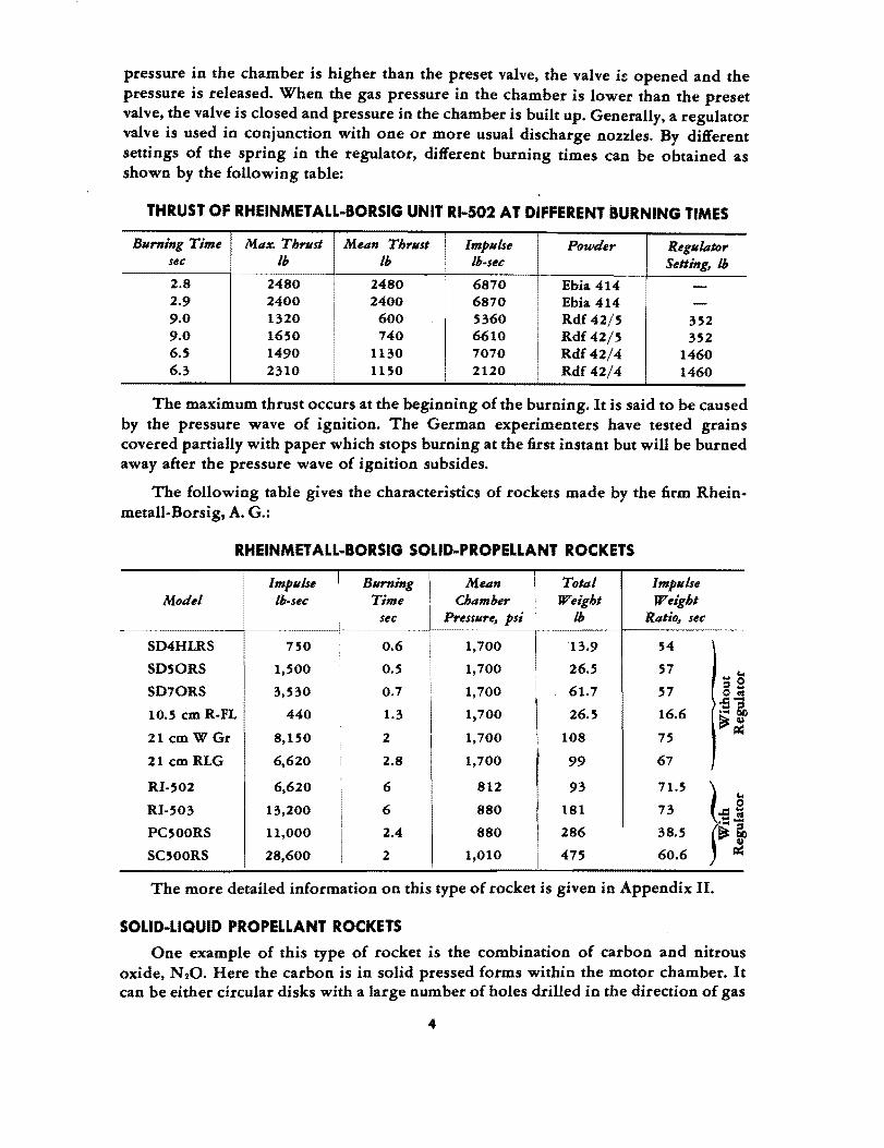
pressure in the chamber is higher than the preset valve, the valve i~ opened and the pressure is released. When the gas pressure in the chamber is lower than the preset valve, the valve is closed and pressure in the chamber is built up. Generally, a regulator valve is used in conjunction with one or more usual discharge nozzles. By different settings of the spring in the regulator, different burning times can be obtained as shown by the following table:
THRUST OF RHEINMETALL-BORSIG UNIT RI-502 AT DIFFERENT BURNING TIMES
Burning Time Max. Thrust Mean Thrust Impulse Powder Regulator sec Ib Ib Ib-sec Setting, Ib 2.8 2480 2480 6870 Ebia 414 -2.9 2400 2400 6870 Ebia 414 -9.0 1320 600 5360 Rdf 42/5 352 9.0 1650 740 6610 Rdf 42/5 352 6.S 1490 1130 7070 Rdf 42/4 1460 6.3 2310 i 1150 2120 Rdf 42/4 1460
The maximum thrust occurs at the beginning of the burning. It is said to be caused by the pressure wave of ignition. The German experimenters have tested grains covered partially with paper which stops burning at the first instant but will be burned away after the pressure wave of ignition subsides.
The following table gives the characteristics of rockets made by the firm Rheinmetall.Borsig, A. G.:
RHEINMETALL-BORSIG SOLID-PROPELLANT ROCKETS
Impulse I Burning I Mean I Total Impulse Model lb· sec Time Chamber Weight Weight
I sec I Pressure, psi Ib Ratio, sec
SD4HLRS 750 0.6 1,700 13.9 54
SDSORS 1,SOO O.S 1,700 26.5 57 ... '"' SD70RS 3,530 0.7 1,700 61.7 57 =9
OtIS -S-
10.5 em R·FL 440 1.3 1,700 26.5 16.6 .... ~ ~o
21 em W Gr 8,150 2 1,700 108 75 A::
21 em RLG 6,620 2.8 1,700 99 67
RI·502 6,620 6 812 93 71.5 I " RI-S03 13,200 6 880 181 73 0
,.c:'" ... tIS
PC500RS 11,000 2.4 880 286 38.5 '''1 ~o SC500RS 28,600 2 1,010 47S 60.6 A::
The more detailed information on this type of rocket is given in Appendix II.
SOI.ID-LiQUID PROPELLANT ROCKETS
One example of this type of rocket is the combination of carbon and nitrous oxide, N 20. Here the carbon is in solid pressed forms within the motor chamber. It can be either circular disks with a large number of holes drilled in the direction of gas
4

Bow, or carbon pressed into small hollow cylinders and then loaded into the chamber with the cylindrical hole in the direction of the gas flow. The oxidizer is nitrous oxide, N20, injected into the chamber at the far end of the nozzle. In order that heat will not be conduted away from the carbon at the chamber wall, a layer of carbon near the wall is left solid without holes. The ignition is accomplished by a small powder charge. In order to make the whole surface of the carbon charge to burn uniformly at once, the holes of the carbon charge are filled with celluloid fillings which act as the initiator. The full thrust is thus developed within one sec. It is estimated that a rocket of this type can be built for 1l00-lb thrust and 40-sec duration.
Another possible combination of this type is the oxidizer, nitrosyl perchlorate, NOCIO. H20 crystals, and the fuel, ammonia, NHa• The oxidizer (code name PCt) can be mixed with carbon and pressed into convenient forms for loading in the chamber. The fuel, NHa, is injected in liquid form and spontaneous ignition is achieved. It is found by. small laboratory experiments (Damkohler and Eggerfluss) that with a chamber pressure of 285 psi the specific impulse is between 180 and 200 sec and the chamber temperature is 2000°C.
LIQUID-PROPELLANT ROCKETS
It is interesting to note that although the German liquid-propellant rocket started with the use of liquid oxygen and alcohol, in more recent developments hydrogenperoxide type propellants and nitric acid-aniline type propellants were emphasized. A few examples of the small liquid-propellant rockets for missile propulsion are given in Appendix III and a list of code names of liquid propellants is given in Appendix IVThe most interesting points found for the research and development of this type of rocket will be given in the following paragraphs.
Liquid Ot and Hydrocarbon
A very ambitious installation for testing this type of rocket was built up by E. Sanger under the direction of A. Busemann at Fassburg (near Celle). The hydrocarbon used was fuel oil. The liquid oxygen was made at the test station at the rate of 165 lb/hr and was stored in a tank of 50-T capacity. The tank is insulated with .3 ft of silica sand material. Bare copper pipe is used for taking the liquid Ot to the test stand. Sanger made great plans. for a 200,000-lb rocket with propellant pumps driven by a steam turbine. The steam for the turbine is obtained through the water-cooling jacket of the motor and is condensed by the liquid 01. However, nothing much was actually accomplished and Sanger left the organization in 1941. Late in 1944, the experiments were taken over by Grumbt who has been in charge of the station until now. The oxidizer by this time was changed to gaseous oxygen for easy handling. The following points are interesting high lights of the results:
(a) The ignition is achieved by diethyl zinc, Zn (C2H 6)2, which was introduced first to the chamber to burn with air in the chamber, then the propellants were immediately introduced. Diethyl zinc is spontaneously ignitable with air.
(b) A systematic test program with the same chamber volume but with different aspect ratios of the chamber was carried out, with the injection at one end of the chamber in the axial direction. Very long and slender chambers were tested. But the most efficient chamber has a length-diameter ratio of approximately 2.
5
(c) At 570 psi chamber pressure, a ratio of volume to throat area ratio (1*) equal to 45 in., an aspect ratio of 2, and aD optimum fuel-oxygen ratio of 2.9, the exhaust velocity measured is 8800 ft/sec.
(d) A tangential injection design with alternating orifices for oil and oxygen was in the machine shop but no test was made.
(e) The present cooling was done by water. It is planned to use liquid 0, at critical pressure to cool the motor. The liquid 0, is to be pumped by a centrifugal pump. The use of critical pressure has the advantage of avoiding the difficulty of boiling of the coolant.
(f) It was planned to measure the jet velocity by an optical method. This method consists of obtaining the spectra of the jet taken 45° with and 45° against the jet axis. The shift of lines due to Doppler's eft'ect gives the jet velocity. This method was suggested by Konen. Sodium salt will be used as the coloring agent.
NsO (GAt-I) CIS Oxidizer.
0 .. Lutz has worked at Ludwigshafen on the problem of nitrous oxide, N,O, injection in aircraft engines at high altitudes to increase the power. Then it was felt that since the liquid N,O tank is carried in the plane, N,O might also be used as the rocket oxidizer for assisted take-oft'. So when Lutz was evacuated to Volkenrode, he started to work on the liquid-propellant rocket with gasoline as fuel and N,O as oxidizer. The chamber temperature was fairly low, approximately 20000 C. The exhaust velocity was approximately 5000 ft/sec.
Hydrogen-Peroxide Propellant.
The hydrogen peroxide was originally developed by H. Walters, K. G., for torpedo applicatiop. It was later found that 80% concentration material is "Spontaneously inBammable with hydrazine hydrate, NtH.· H,O. The mixture of hydrazine hydrate and methyl alcohol is called C-Stoft' and is used with 80% hydrogen peroxide in the propulsion unit of Me-163B rocket fighter plane. The unit has a turbine driven by gas from H,02 decomposition and drives the peroxide pump and fuel pump. The thrust is regulated by controlling the turbine and the maximum thrust is 3650 lb. The cooling is done by C-Stoft'. The chamber pressure at the maximum thrust was 310 psi. At partial thrust, the chamber pressure was, of course, much lower. Therefore, the specific consumption at partiafthrust was much higher than that of the full thrust. At fuJI thrust, the consumption was 18 lb/hrllb-thrust or 19.8 lb/hr/lb-thrust including the consumption of the pumping system. At 1/4-thrust, the consumption was 70% higher than the value given ~bove. Therefore, the cruising consumption was very high. To remedy this situation, two motors were designed: one of 660-lb thrust for cruising and another of 3300-lb thrust for climb. However, the two-motor design was never in production.
Nitric-Acid Propellant.
This type of propellant was developed by the BMW and Luftfahrtforschungsanstalt Munchen as the production of hydrogen peroxide and hydrazine hydrate was rather limited. Thus the German development of this type of propellant started with a healthy practical point o! view. The emphasis was thus on the low cost of the propel-
6
lant but with the shortest ignition lag. This naturally led to the use of mixtures for fuel. The fuel consisted of two components. The so-called "ergoI'" part is generally inert and' not seU-inBammable with the acid. But with the addition of the active component or "initiator" the ignition lag can be made even shorter than that of the initiator alone. Therefore, not only the fuel cost is reduced but also the ignition characteristics are improved. Many of the recent rockets used this type of propellant. For instance, the antiaircraft rocket "Wasserfallu used Salbei-Visol combination.
The Germans have tried a mixture of ammonia, NH., and nitrous oxide, N20, and ammonia dissolved in ammonium nitrate, NH.N020 The Schmidding Co. has advocated "Myrol," which is a mixture of methyl nitrate, CHaN03, and methyl alcohol, CH.OH. But no outstanding success can be claimed.
Sweat Cooling.
For cooling the motor, especially the nozzle, porous materials with liquid seeping through the wall were investigated. It was found in experiments that with the hot gas temperature of 1l00°C and gas velocity 2000 ft/sec, the wall can be maintained at 100°C by using only 0.083 Ib/sec/sq ft. Therefore, the sweat cooling with porous walls is very efficient and has promising possibilities.
ARROW W.N.
INTRODUCTION
As the Bight velocity of the aircraft is increased, the effects of the compressibility of the air become more and more pronounced. It is well known that these effects can be measured by the single parameter called the Mach number. The Mach number is the ratio of the Bight velocity to the sound velocity. If the Mach number approaches one, the aerodynamic characteristics of a wing are radically changed by a decrease in lift and an increase in drag. For the conventional wings used in the present-day aircraft, the radical change occurs generally at a Mach number of 0.74. To avoid the loss of aerodynamic efficiency of the wing at higher speeds, this critical Mach number must be pushed to higher limits by new designs.
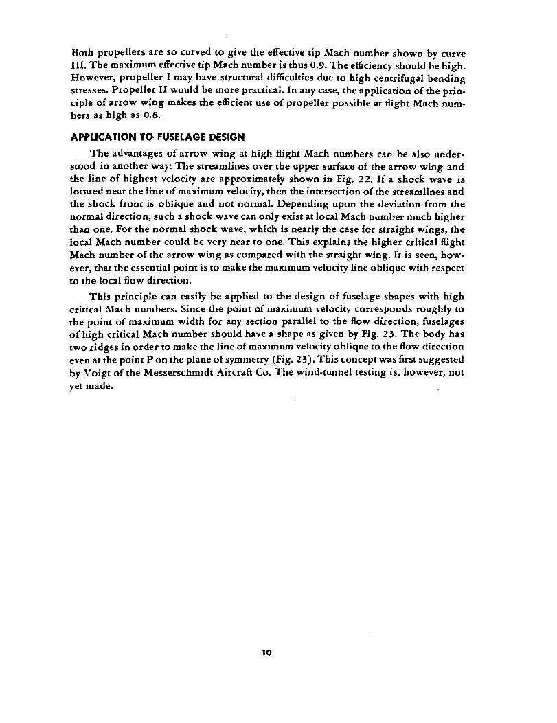
The purpose of the arrow wing, PfeilBngel (Fig. 3), is to raise this critical Mach number. It was fitst suggested for supersonic Bight with Mach number greater than unity by A. Busemann (Ref. I) but the idea was adopted for subsonic Bight velocity by A Bea (Ref. 2). In general the critical number with the same airfoil section can be raised by this means to a Mach number 0.1 higher. For instance, if the straight wing has a critical Mach number of 0.74, then the arrow wing has a critical Mach number of 0.84. Therefore this idea constitutes a most important advance in applied aerodynamics.
7

The most active research institutions engaged in the work on arrow wings were:
(a) Aerodynamische Versuchsanstalt, Gottingen. Director, A. Betz; Wind-tunnel Department, Seiferth.
(b) Deutsche Versuchsanstalt fUr Luftfahrt, Berlin - Adlershof.
(c) Luftfahrtforschungsanstalt Hermann Goring, Braunschweig. Director, H. Blenk; Wind-tunnel Department, Th. Zobel.
THE FUNDAMENTAL PRINCIPLE
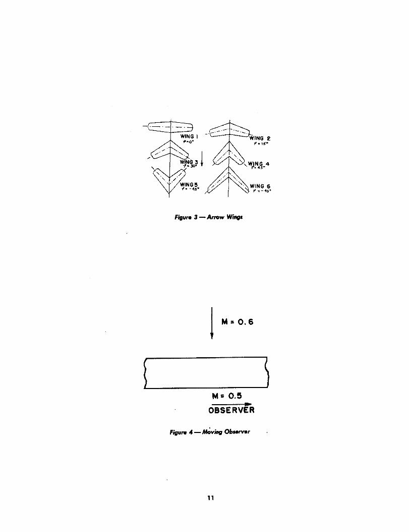
For the moment, consider the air as nonviscous and therefore that no boundary layer exists over the surface of the wing. A wing of infinite span placed in an air stream of Mach number 0.6 with the span of wing perpendicular to the flow direction is shown in Fig. 4. Since the Mach number is below the critical value, the aerodynamic efficiency of the wing is high. Now let the observer of the flow run along the direction ofihe span with a velocity corresponding to a Mach number 0.5. Then to this moving observer, the wing is placed in an air stream of velocity corresponding to the Mach
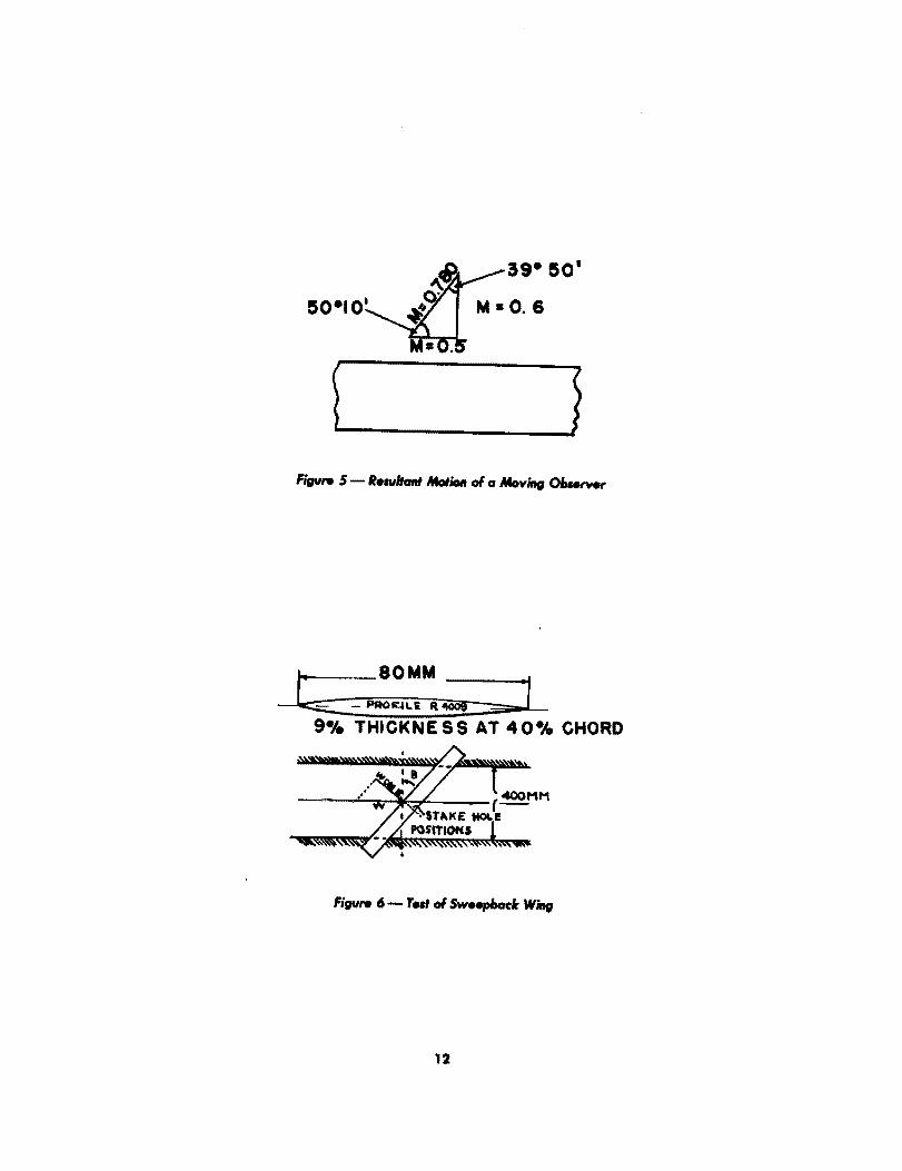
number ~0.62 + 0.5 2 = 0.780, but with the air flow direction making an angle
of tan'! 0.6 = 50°10' with the direction of the span, as shown in Fig. 5. However 0.5
this is the same as saying that the wing is placed in an air stream of Mach number 0.780 and with a sweep back of 90° - 50°10' = 39°50/. Since the fact that the observer is running along the wing span should not change the physical situation of the flow around the wing, the aerodyt.amic forces acting on the wing will be the same as the ;:,traight wing without swet..pback in an air stream of Mach number equal to 0.6.
The only factor neglected in the reasoning is the viscosity of the fluid. Due to the viscosity of the fluid, the velocity of the flow immediately adjacent to the solid surface is zero. Referred to the running observer, the fluid velocity immediately adjacent to the solid surface is not zero but equal to the velocity of the observer. Therefore, with the consideration of viscosity and boundary layer, the analogy between the infinitely long wing without sweep back but observed by a moving observer and the infinitely long wing with sweepback, breaks down. However, since the pressure distribution over a solid body is determined by the flow outside of the boundary layer where the effect of viscosity is negligible, the conclusion reached in the previous paragraph should be essentially true. This is substantiated by a set of experiments made by G. Koch (Ref. 3). In these experiments, the same wing of nine precent thickness was tested at various angles of sweep back (Fig. 6). According to the conscluions given above, the effective velocity is the component V cos {3 of the stream velocity V. Therefore, if p is the static pressure difference at a point on the surface of the wing and the free stream measured at the same values of M cos {3 then p/ q cost{32 should be independent of the angle of sweep back. (M is the free stream Mach number and q is the 1/2PV2.) This is shown to be the case in Figs. 7 to 9.
AERODYNAMIC CHARACTERISTICS OF ARROW WINGS
For practical applications 0f the principle, the span of the wing must be limited and the wing must have a certain symmetry. These are achieved by the arrow wings
8
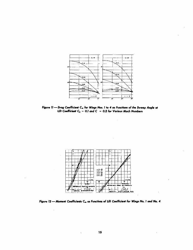
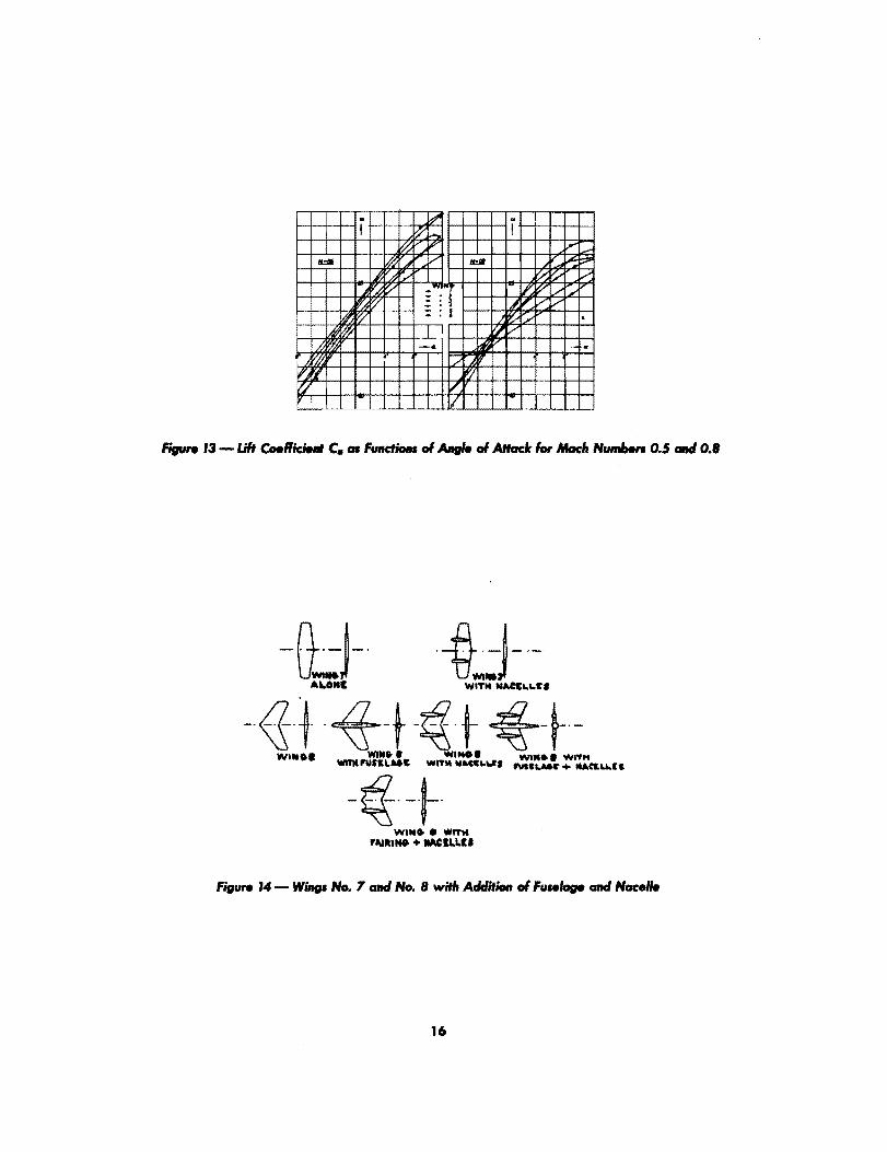
with either forward sweep or backward sweep. However, by so doing, the simple situation of the infinite wing is lost and one must rely on wind-tunnel experiments. A series of tests were made by H. Ludwieg on small models of SO-mm span. The airfoil section is Gottingen 623 (approximately NACA 4412). One group of test wings is shown in Fig. 3, while Figs. 10, 11, 12, and 13 show results. The advantages of the arrow wing is demonstrated in a most clear manner in Fig. 10. In fact with 4.5 0
sweepback, the drag coefficient at M = 1.2 is about the same as for the straight wing at M = O.S.
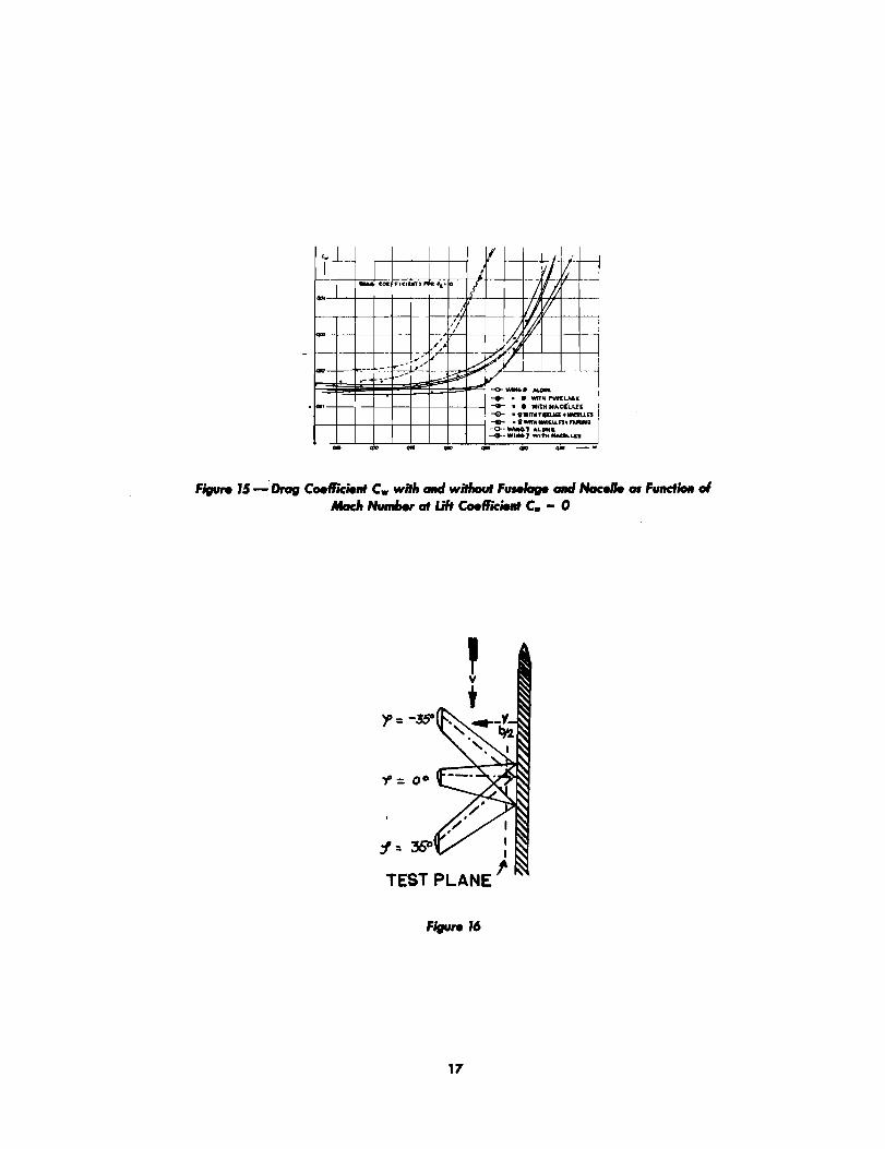
With the addition of engine nacelles and fuselage (Fig. 14) the drag will be larger. However the advantage of arrow wing is still maintained as can be seen from Fig. 15 which shows the results of testing for the models shown in Fig. 14. It is seen that the addition of fuselage has only a small detrimental effect. But the increase in drag due. to the presence of nacelles is considerably larger. This seems to favor the use of a single engine, either propeller-engine combination or the turbojet. Of course, the position of the nacelles could have a strong influence and more detailed experimentation lias to be made before a general conclusion can be reached.
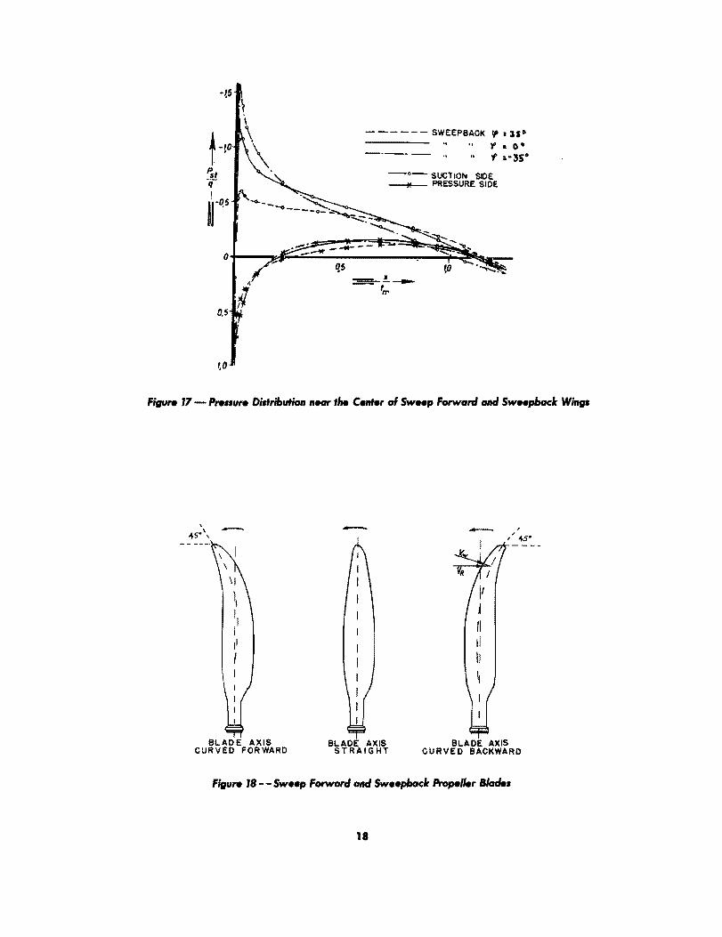
The flow conditions at the center of the span can be simulated by the presence of a large end plate as shown by Fig. 16. It is interesting to see that the pressure distribution near the center of the span is 'not the same for sweepforward and for sweepback as given in Fig. 17. The sweepforward wing has the highest suction peak, the straight wing has the next highest, and the sweepback wing has the lowest suction peak. It is thus expected that the arrow wing without twist will stall at the center first if the sweep is forward and will stall at the tip first if the sweep is backward. This is borne out by experiments. The result of this nonuniform stalling at the different sections introduces the following disadvantages of the arrow wings:
(a) The maximum lift coefficient is smaller due to premature stalling.
(b) There is an undesirable shift of the center of pressure near the maximum lift.
(c) The roll stability and the directional stability are reduced at high lift co-efficients.
(d) The aileron effectiveness is reduced at high angles of attack. These drawbacks of the arrow wing have to be remedied by further research both at low speed and at high speed.
APPLICATION TO PROPELLER DESIGN
The principle of arrow wing can also be applied advantageously to propellers of high tip speeds. Since the speed relative to the blade is higher at the tip than at the root, the blade will be curved either forward or backward, as shown in Fig. IS. The test results (Fig. 20) are shown for blade forms given in Fig. 19 (Ref. 4). It is seen that the forward-curved blade is not advantageous when compared with the straight blade due to undesirable boundary layer interaction. But the backward-curved blade is more efficient than the straight blade, especially at high tip speeds.
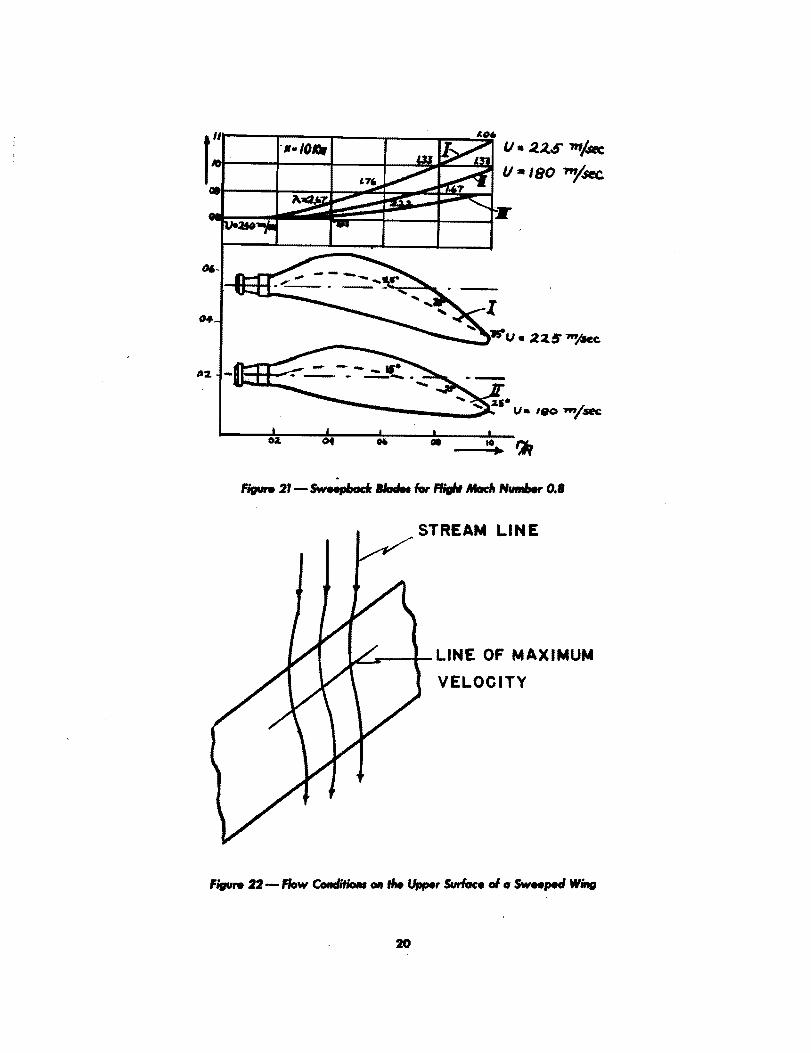
To show,the possibilities of this type of propeller, Fig. 21 is included for a flight velocity of 540 mph at ~2,SOO.ft altitude (M = o.S). Propeller I has a circumferential tip speed of 740 ft/sec while propeller II has a circumferential tip speed of 590 ft/sec.
,
Both propellers are so curved to give the effective tip Mach number shown by curve III. The maximum effective tip Mach number is thus 0.9. The efficiency should be high. However, propeller I may have structural difficulties due to high centrifugal bending stresses. Propeller II would be more practical. In any case, the application of the principle of arrow wing makes the efficient use of propeller possible at flight Mach numbers as high as O.B.
APPLICATION TO-FUSELAGE DESIGN
The advantages of arrow wing at high flight Mach numbers can be also understood in another way: The streamlines over the upper surface of the arrow wing and the line of highest velocity are approximately shown in Fig. 22. If a shock wave is located near the line of maximum velocity, then the intersection of the streamlines and the shock front is oblique and not normal. Depending upon the deviation from the normal direction, such a shock wave can only exist at local Mach number much higher than one. For the normal shock wave, which is nearly the case for straight wings, the local Mach number could be very near to one. This explains the higher critical flight Mach number of the arrow wing as compared with the straight wing. It is seen, however, that the essential point is to make the maximum velocity line oblique with respect to the local flow direction.
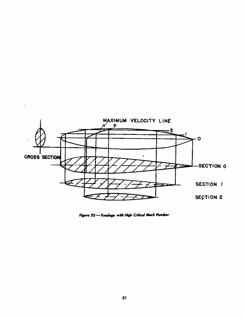
This principle can easily be applied to the design of fuselage shapes with high critical Mach numbers. Since the point of maximum velocity corresponds roughly to the point of maximum width for any section parallel to the flow direction, fuselages of high critical Mach number should have a shape as given by Fig. 23. The body has two ridges in order to make the line of maximum velocity oblique to the flow direction even at the point P on the plane of symmetry (Fig. 23). This concept was first suggested by Voigt of the Messerschmidt Aircraft Co. The wind-tunnel testing is, however, not yet made.
10


RAMJIT
INTRODUCTION
Although there were many attempts in Germany to develop the ramjet as a propulsion power plant, the data and information col1ected and described in the following sections seem to indicate that the work was stiU in its beginning and quite remote from immediate practical applications. However, the stable combustion of fuels at high flow velocities was achieved, at least for the case of gaseous fuels. Furthermore, the test performance of the German ramjet at subsonic forward velocities agrees satisfactorily with the computed values made in the United States. There are also a few interesting concepts about the general design of the ramjets as given in "Design Concepts," page 24.
GERMAN RAMJETS
Fa. Walter Company of Kiel has designed a ramjet model which was tested at the Luftfahrtforschungsanstalt Hermann Goring (LFA), Volkenrode. (The data were given in Untersuchengen und Mitteilungen Nr. 2014, "Untersuchungen am LTriebwerk der Fa. Walter, Kiel. in Hochgeschwindigskeitskanal A9 ander LFA," 1 May 1943.) The cold unit has a drag coefficient equal to 0.3. The net thrust increases first with increase in fuel injection but then it decreases again. The maximum value of net thrust increases with velocity. However, the net thrust coefficient (net thrust divided by the product of dynamic pressure and the frontal area) decreases from 0.4 to 0.3 from Mach number 0.42 to 0.85. The unit can be ignited with wind-tunnel velocities up to 700 h/ sec. The burning can be controlled by regulating the fuel injection pressure up to the highest wind-tunnel test speed (M = 0.85). However, the burning was not very smooth. The fuel consumption was 7 Ib/hr/lb of net thrust at M = 0.8 .
. E. Singer has built a very large ramjet of 2-m diameter on top of a Dornier-217 bomber. and flown from Ainring to Fassburg. The burning of the ramjet was not smooth and the pilot reported barely noticeable thrust at the high speed of the airplane.
After failure of Singer's attempt, the development of ramjet was taken over by the Focke-Wulf Company at Bad Eilsen under the direction of Pabst. To reduce the external drag, the unit was designed very short using outside compression. It is claimed that the loss of total pressure in the diffuser was only from 3 to 5 %. The burners in the combustion chamber were designed for gaseous fuel. Each burner consisted of a conical bel1 with the vertex pOInted downstream. The gaseous fuel was led to the cone through a tube attached to the base (Fig. 24). The fuel then streamed out of the annular space between the cone and a disk at the base of the cone. The eddy and tur-
22
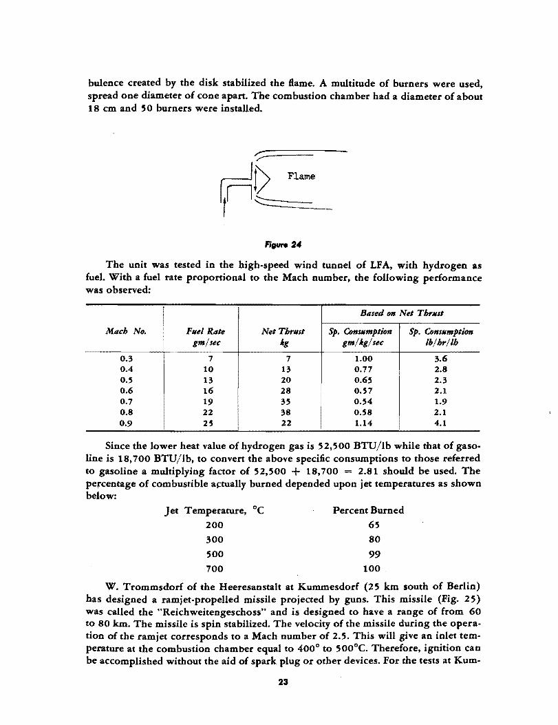
bulence created by the disk stabilized the flame. A multitude of burners were used, spread one diameter of cone apart. The combustion chamber had a diameter of about 18 cm and 50 burners were installed.
r~_Flame
The unit was tested in the high-speed. wind tunnel of LFA, with hydrogen as fuel. With a fuel rate proportional to the Mach number, the following performance was observed:
Based on Net Thrllst
Mach No. Fllel Rate Net Thrlls' Sp. Consllmption Sp. eonsllmption gm/sec ig gm/ig/sec Ib/hr/lh
0.3 7 7 1.00 3.6 0.4 10 13 0.77 2.8 0.5 13 20 0.65 2.3 0.6 16 28 0.57 2.1 0.7 19 35 0.54 1.9 0.8 22 38 0.58 2.1 0.9 25 22 1.14 4.1
Since the lower heat value of hydrogen gas is 52,500 BTU/lb while that of gasoline is 18,700 BTU/lb, to convert the above specific consumptions to those referred to gasoline a multiplying factor of 52,500 + 18,700 = 2.81 should be used. The pe~centage of combustible a~tually burned depended upon jet temperatures as shown below:
Jet Temperature, °C Percent Burned
200 65
300 80
500 99 700 100
W. Trommsdorf of the Heeresanstalt at Kummesdorf (25 km south of Berlin) has designed a ramjet-propelled missile projected by guns. This missile (Fig. 25) was called the HReichweitengeschoss" and is designed to have a range of from 60 to 80 km. The missile is spin stabilized. The velocity of the missile during the operation of the ramjet corresponds to a Mach number of 2.5. This will give an inlet temperature at the combustion chamber equal to 400° to 500°C. Therefore, ignition can be accomplished without the aid of spark plug or other devices. For the tests at Kum-
23
mesdorf, the fuel used was carbon disulphide, CS., for easy ignition. The fuel is injected into the combustion chamber by the pressure at the wall of the fuel tank created by the rotation.
The combustion chamber was designed by R. Edse of the Luftlahi1:forschungsanstalt Herman Goring (LFA). It was divided into segments. The inlet velocity was approximately 100 m/ sec. However, Edse was not able to make the static test of a single segment of the chamber due to manufacturing delays. However, it was planned to inject octyl nitrate, CaHl'tNO., to promote combustion.
DESIGN CONCEPTS
Diffusers were tested at the supersonic wind tunnels at LF A. It was found that with the usual duct. opening a nonnal shock wave always forms ahead of the duct opening and the diffuser efficiency was rather poor. To improve the design, the entrance was made annular by introducing a central cone protruding ahead of the duct. The cone generated an oblique shock wave. The diffuser efficiency was thus improved as the loss through an oblique shock is always smaller than the loIS through a normal shock.
For short-duration operation, the burning of coal in the ramjet was investigated. The coal was loaded in the combustion chamber as slabs made of coal powder and a binder. The advantages of this scheme are (a) the use of a very cheap fuel, and (b) the simplicity of design by avoiding fuel injection systems. However, difficulty wa. encountered in the experiment due to incomplete combustion with the production of CO instead of CO .. For complete combustion at high Sow velocities, either turbulence has to J:>e introduced or the chamber has to be made very long. It was plaoned to solve this problem by additives which would promote combustion. The proponents of this
. type of ramjet are Lippisch and E. SiDger.
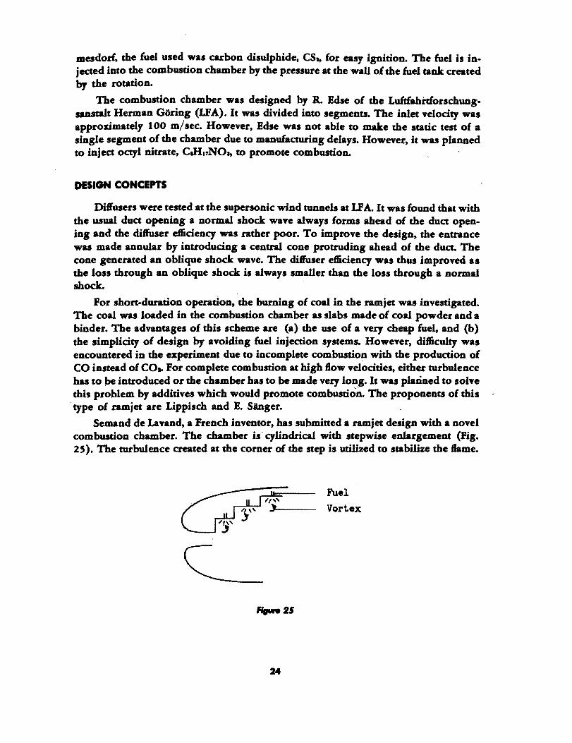
Semand de Lavand, a French inventor, has submitted a ramjet design with a novel combustion chamber. The chamber is' cylindrical with stepwise enlargement (Fig. 25). The turbulence created at the corner of the step is utilized to stabilize the Same.
,.".25
24
Fuel Vortex

AIROPULSI
HISTORICAL DEVELOPMENT
P. Schmidt started to work on the aeropulse in 1935 under the auspices of the German Air Ministry. His first step was the design and testing of an ignition device to give 50 cps. This device is mechanical and the ignition ·in itself was achieved by the compression of a fuel-air mixture with a free piston. The air valve in front of the tube was essentially of the form used now. However, the injection device for fuel was very complicated. It consisted of a very large number of wire-game-covered orifices with fuel pressure applied against the flow direction. It was claimed that by so doing, a constant fuel-air ratio could be maintained for all air velocities. During the initial run of this design, it was found that although the ignition device was giving 50 ignitions/ sec, the tube itself was operating at 100 cps which was the natural frequency of the tube. The ignition device was thus unnecessary and was discarded.
In 1939 or 1940, the Argus Motor Company, Berlin, started their work on the aeropulse, first with an air valve of their own design. This design consisted of a spiral air passage which has much less resistance for air to go into the motor chamber than for air to go out of the motor chamber. The fuel-injection system was, however, very simple and consisted of a single orifice. The frequency was approximately 50 cps. Later the good features of the Schmidt and the Argus designs were com· bined. The complicated injection system of Schmidt and the bulky Argus air valve were discarded, and the aeropulse took practically the same form as it has now.
About 1941, Schelp ofthe German Air Ministry saw the potentiality ofthe engine and suggested the application to propel a small unmanned bomber, since the development of the V-2 was not ready for practical applications. The airframe was designed by Fiessler Aircraft Company. The result is the V -I. The detailed aerodynamic development of the aeropulse was done at the Luftfahrtforschungsanstalt Herman Goring (LFA), Volkenrode, in the 2.8-m high-speed wind tunnel. For these tests the return section of the wind tunnel was removed and the tunnel operated as an Eiffel-type tunnel to allow for air exchange.
ENGINEERING DEVELOPMENT
A. Busemann of the Gasdynamics Department of LFA was consultant to the German Air Ministry for determining whether the research and development work on the aero pulse should be continued at the end of each contract period. Thus he knows the complete history of the engineering development. The following is a brief summary of the interesting points found about the German aeropulse.
Aerodynamics 01 Aeropv/ ...
The original aeropulse made by the Argus Company when brought to LFA for ,:"ind-tunnel tests had the spring-air valve mounted directly at the front of the duct
25
without any cowling. The external drag of the duct was found to be very high. Thus, although the static thrust of the engine was 600 lb, the net thrust of the engine at 380 mph was zero. To reduce the drag, the air valve was enclosed in the cowling as in the present engine. The velocity for zero net thrust was then increased to 435 mph. By further detailed improvement in the fuel-injection system, the net thrust was increased to 660 lb from zero air speed to 340 mph. The speed for zero net thrust was further increased to 560 mph. Therefore there is still possibility of improvement in the aerodynamic design and fuel-injection system. Such research, however, is only possible in a high-speed wind tunnel as the external drag of the unit is of great importance and must be included in the investigation.
For further increase in the thrust of the aeropulse, the effective inlet area of the air valve must be enlarged. The present design has only 60% effective opening with 40% of the area occupied by the grids. With the enlargement of inlet area, the mass air flow will be increased and consequendy larger thrust can be obtained from a given engine. For instance, by removing part of the rib in the grid of the spring valve, the static thrust was increased from 660 to 880 lb. The specific consumption was reduced from 3 Ib/hr/lb of gross thrust to 2.8 lb/hr/lb of gross thrust. This development was done by Eisla and G. Dietrich of the DFS at Ainring. To reduce the external drag, the duct could also be built into the fuselange. *
Air Augmentation.
If air alone could be introduced to the duct behind the explosive air-fuel mixture, then when the mixture is exploded, it will act as a piston to push out the air column. The total air mass per explosion is thus increased with resultant larger momentum and better efficiency. The air and air-fuel mixture must be separated. This is for two reasons: (a) A very lean mixture will not bUrn properly. (b) Even if the mixture did burn properly, the explosion pressure would be too low for effective energy utilization.
P. Schmidt was working on this principle. It was done by the addition of a second spring valve after the combustion chamber for additional air flow only with fuel injection. According to Busemann, no marked degree of success has yet been achieved.
Combined A.ropu/ •• and Ramjet.
Another suggestion of Dietrich was the mounting of the aeropulse at the entrance to the ramjet. Then at low flight velocities, no fuel is injected into the ramjet duct and the ramjet duct acts as an augmentor. At high flight velocities, the thrust of the aeropulse tends to fall but it could be used as an ignitor for the burning of the fuel injected into the ramjet duct. It was hoped thus to obtain increasing thrust over a wide range of flight velocities and furthermore, the device will be self-starting.
Mult;'ub. Units.
W. Kamm of Stuttgart tried to reduce the large variation of thrust with respect to time of a single aeropulse by multiple mounting. However it- was found that due to
• An interesting side line of the development is the engine warmer for cold-weather operation built on the same principle as the aecopulse. Only here the jet is used to induce additional air into the hot-air pipe to the engine.
26

difference in phase of operation, the charge of air at the end of one tube was hindered by the discharge of hot gas at the end of the other tube. There was considerable flow of hot gas from one tube to the other tube and thus reduced the air density in the tube at the end of the charging process. The result was that the thrust of a two-tube combination was smaller than twice the thrust of a single tube. This difficulty is not yet solved.
INSTALLATION OF TURBOJETS IN AN AIRPLANE
INTRODUCTION
The installation problem of the conventional engine and propeller-propulsive system consists in finding the optimum location of the power plant so that the increase in drag due to interference will be a minimum and no undesirable influence will be exerted on the control surfaces. Of course the same problems also exist in the case of turbojet-powered airplanes. Due to the high velocity of the jet and the high temperature of the exhaust gas, the influence on other parts of the airplane is even stronger than in the case of the conventional power plant. Therefore the instiillation problem is one of the most important problems in jet-airplane design.
SIMULATED MODELS OF TURBOJETS FOR WIND TUNNEL TESTING
To study such installation problems, wind-tunnel testing is the most convenient method. Most of the study done in Germany was made by the staff at the Aerodynamische Versuchsanstalt Gottingen (AVA). The first thing to be determined is, of course, the best way of simulating the turbojets in model tests. The A VA (Ref. 6) simulated the turbojets by a combination of electric motor-driven fan and heat addition by burning alcohol. The air entering the model duct was compressed by an axial fan, then the compressed air was heated by burning with alcohol and discharged out of the duct. The fan in the duct was driven by an electric motor. Since only moderate discharge velocity was required due to low wind-tunnel velocity compared with Bight velocity, the fan was single stage. Alcohol was chosen as the fuel for smooth combustion.
The first question to be setded was whether the heat addition by burning is absolutely necessary. Of course the answer is conditioned by the particular aerodynamic characteristics to be studied. If the flow characteristic around the turbojet is the essential point, then it was found that heat addition is not necessary. Accurate enough results can be obtained if one makes the momentum changes from inlet to oudet of the duct equal for both cold jet and hot jet. The later Gottingen tests were generally made with cold jets. However, due to the difference in the spreading of cold jets and of hot jets, studies on the aerodynamic characteristics involving the wake of the jet (such as tail surface characteristics) can only be accurately made with a hot jet.
If the momentum increases of the cold jet and the hot jet .re made to be equ.l, the mass Bows will not be the same. This situation can be remedied by (a) proportionally
27

decreasing the exit area of the cold model so that both momentum changes and mass flows will be the same, and (b) introducing a gas of lighter density into the duct to reduce the density of the exhaust from the cold model. However, it is easy to see that both methods lead to difficulties.
AERODYNAMIC TESTS WITH TURBOJET MODELS
The first problem was the aerodynamic characteristics of the turbojet duct itself. Here studies of the lift, movement, and thrust (or drag at low jet power) were made. (Refs. 7, 8, and 9.)
The second problem was the interference drag of the duct and the wing. Here the emphasis was on the smallest possible increase in surface velocity which was measured by pressure holes. This is for delaying the appearance of shock wave at high flight Mach numbers. It was found that for the arrow wing, the optimum fairing of the duct and wing is rather complicated, being unsymmetrical due to the characteristic flow pattern over the arrow wing. (Refs. 10 and 11.)
The third problem was the influence on the aerodynamic characteristics of the jet on an airfoil placed at various positions to the duct. A first approximation to the problem was made with a cold jet (Ref. 12). However, A. Busemann mentioned an interesting fact about the behavior of the hot jet from actual turbojet units. He said that the jet mixed smoothly with the surrounding air, as expected, to a distance of about eight diameters of jet. Then instability set in and big slow vortices of one·half second period gave much trouble in tail buJfeting.
INLET DESIGN FOR THE DUCT
Two types of inlets were considered: The duct inlet for external installation, i.e., turbojet duct separate from the rest of the airplane and the duct inlet for internal installation where the turbojet is submerged in the airplane. For the external installation, it was found (Refs. 13 and 14) that the leading edge of the duct should have a wellrounded shape to give satisfactory performance at all flight velocities and angles of attack (see also Refs. 7,8, and 9). The internal installation with the duct submerged in a sweep back wing is particularly difficult due to the unsymmetrical flow over a sweepback wing. (Ref. 15.) Here general principles are difficult to find. Each individual case can best be studied separately. However, from the tests it is seen that the total head loss through this entrance can be reduced to 10%.
28

GAIDYNAMICS WIIH IUPERIONIC VELOCITIEI
INTRODUCTION
The main Germanitffort of investigating the supersonic flows seems to be concentrated on the following subjects:
(a) Aerodynamic characteristics of shells and missiles.
(b) Flow problems in connection with the design of aeropulse and ramjets at high speeds.
(c) Detonation or shock waves.
Item (b) was tteated in the reports on the aeropulse and the ramjet. Item (c) is essentially a combined aerodynamic and chemical phenomenon. The aerodynamic aspect of the problem is reduced to the problem of cylindrical and spherical shock waves. Only theoretical work was done on this subjea.
EXPERIMENTAL INVESTIGATION OF SHELLS AND MISSILES
The experimental investigation of shells and missiles was carried out by both iring and wind-tunnel testing. For the firing tests, the most interesting equipments are the two firing tunnels at the Luftfahrtforschungsanstalt Herman Goring at Volkenrode. One tunnel is 400 m long, with S.4 m diam at the firing end and 7.6 m diam at the target end. It can be evacuated to O.OS atm corresponding to 72,200 ft altitude. The evacuation is done by a soo-kw exhauster, and complete evacuation is done in 4 hr. Thus ballistic measurements can be made at exttemely reduced air density. In addition, there is a cross-wind firing channel which is 30 m long and 0.6 m wide. Here a cross wind up to 200 m/sec is created by discharging ftom free air to an evacuated tank of 3000 m' volume. At this cross-wind velocity, the test duration is 0.6 sec, suftident for ballistic tests.
The wind-tunnel tests were carried out at the following institutes:
(a) Aerodynamische Versuchsanstalt, Gottingen: (AVA) O. Walchner responsible.
(b) Heeresanstalt PeenemdDde (HAP) (moved to Kochel since January, 1944); Hermann responsible.
(c) Luftfahrtforschungsanstalt Hermann Goring, (LFA) Volkenrode; A. Busemu.n responsible.
(d) Aerodynamisches InstitUt der Technischen Hochschule Aachen (AlA). The detailed description of these wind tunnels is given in the report on wind tunnels.
The main problem here is, first of all. to test the reliability of the wind-tunnel experiments as a means of measuring the aerodynamic characteristics of shells. Three
29

questions can be asked: (1) the effect of wake distortion due to the reHected bow wave and the presence of model support; (2) the effect of Reynolds number on skin friction and base pressure; (3) the effect of the absence of rotation of the shell. Both A VA and HAP have measured a series of shell forms for normal forces and drag forces at different Mach numbers and angles of yaw. The fact that these two sets of tests on the same shell shape do not check, with AVA data being lower, seems to show the effects of items (1) and (2). For a sphere, these effects are known to be small, for the experimental results check among themselves and also check firing tests.
To test the effect of item (3), a rotating wind-tunnel model was tested. The model is rotated by a small electric motor at about 30,000 rpm. The result shows that the effect of rotation on the lift of the shell is zero at small angles of yaw, small but negligible at large angles of yaw (10°). However, there is a small and definite increase in drag of about 3.5% due to rotation ofthe shell. The lift also tends to shift to the base of the shell slightly by rotation.
Therefore, in general it can be said that the German investigations indicate that the main difficulties of wind-tunnel testing of shells is the effect of wake distortion and difference in Reynolds number of model and the shell. The effect of rotation on forces is small, but possibly the boundary layer thickness is greatly increased due to centrifugal forces. (Refs. 17, 18, 19, and 20.)
The problem of control and stability of fin-stabilized wingless projectiles or finstabilized winged projectiles was intensively investigated by the HAP. The controls were all located at the fin surfaces; the wing surfaces had no ailerons. The two main problems are (1) to reduce the hinge moment for a given control moment so that smaller and lighter servos can be used; and (2) to reduce the variation of the distance between the aerodynamic center and the center of gravity of the missile throughout the working Mach number range so that the control moment necessary for various angles of attack can be kept at a smaller value.
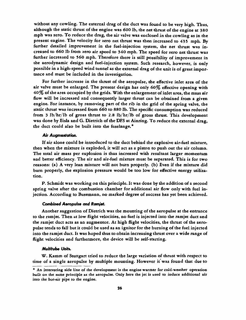
To solve the first problem, aerodynamic balance has been tried. However, it was found that to obtain the necessary aerodynamic balance at supersonic speeds, the surface becomes aerodynamically overbalanced for a small range of control surface angle around the neutral position. Then biplane control surfaces were tried. The drag of such surfaces was too high. Furthermore, spoilers were found to be unsatisfactory as their effectiveness at supersonic Hight velocities is much smaller than hinged surfaces. The best solution obtained so far was the tandem surfaces as shown in Fig. 26. The desired hinged moment characteristics can be obtained throughout a very wide range of Mach numbers without overbalance.
The second problem for the winged missile is a rather difficult one. Various shapes of the wing surfaces were tested. The best design is the short tapered plan form as shown in Fig. 27.lt was found that for such wing surfaces, the aerodynamic center moves very little for Mach number variations from subsonic to supersonic velocities.
The dynamic characteristics of the missile, in particular the damping characteristics, were studied by supporting the model at the center of gravity and then releasing it from a displaced position. The subsequent motion is recorded by high-speed photography.
30
THE INFLUENCE OF THE ROCKET JET ON THE AERODYNAMIC CHARACTERISTICS OF A MISSILE
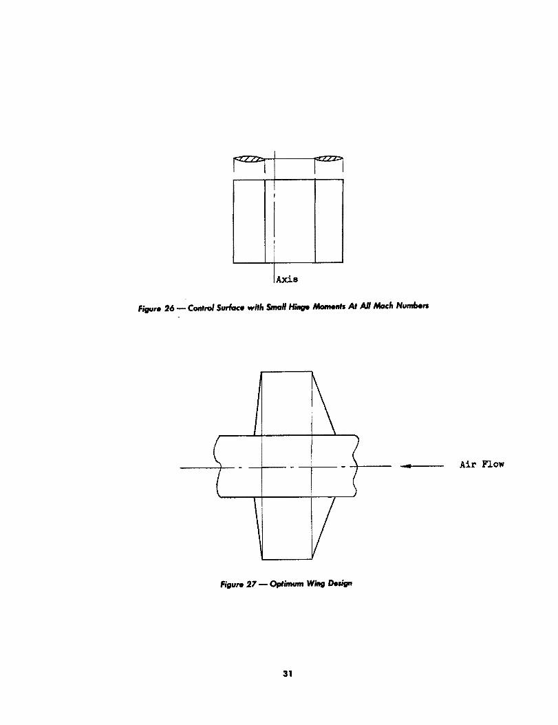
The effect of the presence of a rocket jet at the tail of a missile was investigated by the HAP. In the wind-tunnel tests, the rocket jet was simulated by a hot air jet. The hot air was led to the model from a source outside the wind tunnel. It was found that the presence of the jet has a marked influence on the drag of the missile. Due to the suction effect of the jet, the air flow over the tail end of the missile was accelerated and the pressure in tit is region was thus lowered. Therefore, the drag of the body was increased. At high Mach numbers, however, the presence of the jet eliminated the low pressure wake at the base of the missile and this would decrease the drag. For die particular projectile shape of V-2, it was found that at supersonic velocities the influence on the base drag overbalanced the influence on pressure drag over the downstream part of the body, and the drag was decreased by the jet (Fig. 28).
Without Jet o
Figure 28 - EIIect oIlloc".t Jet 011 tIte DrarI 01 a Missile
The presence of.the rocket jet also gready increased the damping of the missile for yawing oscillations. This effect was measured by mounting the rocket statically but allowing it to oscillate. The motion was measured and the damping coefficient deduced. It was found that the increase in damping can be fully explained by the change of angular momentum of the body plus the propellant contained in the tanks. Due to the discharge of the mass, the change of angular momentum contained a term which can be interpreted as the damping moment due to the rocket jet.
THEORETICAL INVESTIGATIONS
Shell .. The supersonic flow over a pointed body of revolution at zero angle of yaw is
solved by the method of characteristics (Ref. 21). This solution can then be used as the basic solution or zero approximation for calculating the flow of the same body at small angles of attack and slow oscillation (Ref. 22). Thus the problem of supersonic Bow over shells and missiles is satisfactorily solved. .
32

Oscillating Airfoil ••
The two-dimensional How over an oscillatinl!J airfoil in supersonic How was linearized (small oscillation and thin airfoil) and completely solved with numerical values of the aerodynamic forces given for free stream Mach numbers up to S.
Interadion of Boundory Lgyer ond SItocIc Wove.
The boundary layer separation due to shock wave gives the forked shock wave. These forked shock waves were calculated and the results given in the form of diagrams. An allied problem is the question of whether it is possible to have a shock wave formed awav from the surface of continuous curvature. W. Tollmien has shown by a particular example caiculated with the method of characteristics this is possible even in a non viscous fluid. The pressure distribution over the surface is continuous but has a rather sharp rise near the shock. Along the streamlines intersecting the shock wave, the pressure is, of course, discontinuous at the shock. Such investigations will be a great aid in understanding the problem of shock and boundary layer interaction.
Cltaplygin Metltod lor Two-Oimensional flow.
Guderly has used the asymptotic form of the hypergeometric functions to effect a summation of the infinite series of Chaplygin's solution for the two-dimensional flow over a body in uniform motion.
SUPERSONIC WIND TUNNEL DESIGN
A. Busemann is of the opinion that a rectangular test chamber has the advantage that it is easier to avoid shock-wave formation. Furthermore, German wind-tunnel designers seem to prefer a construction which has two closed sides for optical measurement with the other two sides open. This design is said to give better freedom for model support and housing of the balance. However, a price is to be paid in compressor power as the pressnre recovery is lower in the diffuser. This fact is shown by the following table (Ref. 23) which corresponds approximately to the optimum design:
Subsonic diffuser half angle :: 30
Test section length :: 1.2 S height of test section (H) Length of supersonic diffuser:: 1.87 H Width of test section = H
I Closed Section Open Section
Height Test Section Throat Height
He~ht ot. Di IIser oj Diflllser Mach No. H 'broat, H PdP. Throat, H
1 1 1.020 0.86 1.100 1.4 0.900 0.950 0.77 1.074 1.8 0.713 0.845 0.65 "1.022 2.2 0.500 0.772 0.54 0.971 2.6 0.343 0.738 0.43 0.894
Pd = pressure at end of diffuser Po == pressure at entrance to the nozzle of test section
33
PdP. 0.78 0.70 0.53 0.3 0.2
6 5
BOUNDARY LAYERS AND THE INTERACTION OF
BOUNDARY LAYERS AND SHOCK WAVES
IN TRANSONIC FLOWS
INTRODUCTION
Until very recently, it was generally believed that the effects of Mach number and the effects of Reynolds number could be separated. In other words, when the effects of compressibility of air are investigated, the Reynolds number of the tests need not be as large as the prototype. Hence a considerable saving in the driving power of the wind tunnel could be achieved by reducing the density of the air. This is, in fact, the basic design principle of most of the recent high-speed wind tunnels. During the latter part of 1944 and early 1945, there was a growing suspicion in the United States of the strong interaction of boundary layer and shock wave: i.e., a strong interaction of Reynolds number and Mach number. This effect is most dearly demonstrated by a series of tests made by J. Ackeret of the ATH at Zurich. The study of this phenomenon naturally divides itself into the investigation of the boundary layer itself and then the investigation of the interaction. The following is a brief description of the salient points in the experimental results obtained.
COMPRESSIBLE BOUNDARY LAYER INVESTIGATIONS
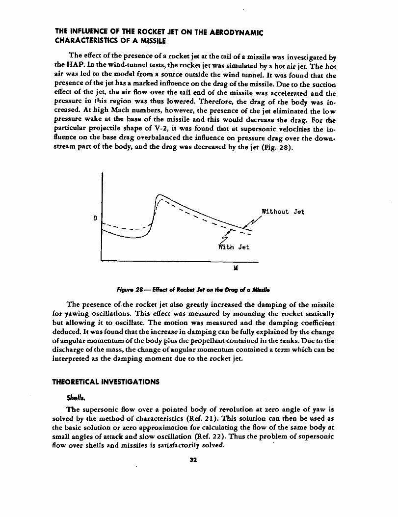
The wind-tunnel group of the Heeresanstalt Peenemunde (HAP) at Kochel has tried to use the Schlieren method to measure the thickness of the boundary layer. However, it was soon discovered that the thickness of the boundary layer appearing in the Schlieren photograph was related to the width of the plate or 'the width of the light path perpendicular to the flow direction. By increasing the width of the plate, the apparent thickness of the boundary layer also increased. Then it was reasoned that this phenomenon could be explained by the strong density gradient in the direction normal to the light path. This strong density gradient causes the light ray to bend away from the solid wall. This effect is stronger when the width of the plate is larger or path of light ray in this varying density layer is longer. Therefore, apparent boundary layer also will be thicker (Fig. 29).
Direct10n ot DecreadD& Dens1ty
~~Ir---------~·.-7777777777
Figu ... 29 - SemliltfJ oI,he Urlbt Roy Due to Transve,... o.Mity Gradient (Flow Velocity Perpendiculor to Paper)
34
To avoid this effect, the HAP investigators returned to the direct mechanical method of Pitot tube. However, the method is somewhat clumsy and the experiment was not vigorously pursued.
INTERActiON OF BOUNDARY LAYER AND SHOCK WAVE
J. Ackeret of the Zarich Poly technical University used his supersonic wind tunnel at subsonic speeds and thus had sufficient power of the driving motor to operate at high density and hence high Reynolds number. For this series of tests, the upper and lower surfaces of the test section were curved and a rather large-chord thin airfoil was used (Fig. 30.) The boundary layer at the tunnel wall was, of course, turbulent. But the boundary layer over the upper surface of the airfoil was laminar at the beginning. Ackeret made a series of experiments at constant Mach number of the free stream but gradually increased the Reynolds number by increasing the density of the air in the tunnel. Then the following int.eresting phenomenon was observed:
// / / ////////.~
AlI":roU •
77
Figure 30 - Acl.,..,', ,.., Set-Up
At small Reynolds number, the transonic flow over the upper surface of the airfoil gave the familiar A-shock formation as shown in Fig. 31. The boundary layer was very much thickened by passing through the first oblique shock but not separated. However, after the second shock, the boundary layer was badly separated. By increasing the Reynolds number but keeping the free .stream Mach number constant, the location of the oblique shock seemed to be fixed but the main shock wave gradually moved forward. The separation of the boundary layer was also somewhat reduced. By still increasing the Reynolds number, the oblique shock suddenly disappeared with only the straight shock (Fig. 32) remaining. The boundary layer separation was also much less due to the absence of the thickening effect of the first oblique shock. Thus the drag of the airfoil was much smaller at high Reynolds number than at low Reynolds number with the same Mach number.
35
:Ma1n Shook
Bad Separation
/ Boundary Layer Laminar
Figure 31-Shoelc Formation at Small Reynol. NumlHtr
Single Shook
Boundary Layer Turbulent
Figure 32 - Shoelc Formation at Large Reynolcla NumlHtr
Ackeret further showed that the oblique shock was due to the unstable character of the laminar boundary layer. For if the boundary layer was made turbulent by a small wire in front of the leading edge of the airfoil, the A - shock formation did not appear even at small Reynolds number. Therefore the disappearance of the oblique shock at high Reynolds number in the first series of tests must be due to the natural transition of the laminar boundary layer to turbulent boundary layer before reaching the supersonic flow region and thus constitutes the most clear demonstration of the interaction of Reynolds number and Mach number.
36
LIQUID EXPLOSIVE BOMBS
INTRODUCTION
It was calculated that by using gasoline and nitrogen tetraoxide N20. mixture, the heat value can be increased by 50% over the usual high explosive on equal weight basis and by 20% on the equal volume basis. However, such a mixture is not safe to handle, so the mixing is actually accomplished after the fuse is armed. This is possible with liquids.
The work on this type of bomb was started at the test station at Fassburg, the rocket test station of LFA, in 1942, but there were many interruptions due to accidents with loss of personnel. Similar work was carried on at Heeresanstalt Peenemunde with different liquid combinations.
DESCRIPTION OF TEST BOMBS
The oxidize!' component, N20., of the bomb has a very narrow range of temperature for which the material exists as a liquid at ordinary pressure. By some pressurization, this temperature range is extended. The whole range is then shifted to lower temperatures by addition of a few percent of a second material. The fuel component is gasoline. The ratio of the two components is on the rich mixture side, i.e., contains more fuel than the stoichiometric mixture.
The two compartments containing these liquids are separated by a dead space so that the chance of piercing both compartments by a bullet is reduced. After the bomb is released from the aircraft, the compressed air in a small container pushes the gasoline through a series of nozzles to spray into the liquid N20 •. The mixing is estimated to be completed in 10 seconds. Then the bomb is exploded by the usual fuse upon contact with the target.
It was found essential to avoid nitric acid in N20 •. The mixing of HN03with gasoline in the presence of N20. tends to generate enough heat to ignite the bomb without the fuse. This fact was used to explain an accident during the testing.
The work was done under the direction of A. Busemann. Many drop tests from airplanes were made. Later, for more accurate measurement of explosion characteristics, the bombs were sent to Dr. Madelung for tests.

REFERENCES
1. A. Busemann, "Aerodynamischer Auftrieb bei Uberschallgeschwindigkeiten," 5th Volta Congress in Rome (1935).' ,
2. A betz, German Patent.
3. G. Koch, "Druckverteilungsmessungen an schiebenden Tragtlflgel," Lilienthal-Geselschaft, Bericht Nr. 156 (1942).
4. H. Ludwieg, "PfeiltlUgel bei hohen Geschwindigkeiten," Lilienthal-Gesellschaft, Bericht Nr; 127 (1940).
5. A. W. Quick, "Aerodynamische und fiugmechanische Fragen der Luftschraubenentwicklung," Schriften der deutschen Akademia der Luftfg. Heft 1063/43g (1943).
6. Brennecke, "Messungen an dem Modell einer Strahlantriebsgondel," Porschungsbericht Nr. 1723 (1943).
7. Bauerle, "Untersuchungen an dem Modell eines Strahltriebwerkes," 1 Teil, Untersuchungen und Mitteitungen, UM, Nr. 3089 (1944).
8. Baurle, and Weber, "Der Anbau von TL-Triebwerken und den Tragtlflgel," 1 Teil, UM, Nr. 3147 (1944).
9. Eggert, "Druckverteilungsmessungen an Heck einer Strahlgondel fflr Bestimmung des Langsmomentes," UM Nr. 3179 (1944).
10. Bauerle, and Conrad, "Der Anbau von TL-Triebwerker an den Tragfiflgel," 3 Teil, UM Nr. 3158 (1944).
11. Buschner, "Der Anbau von TL-Triebwerken an den TragtlUgel," 4 Teil, UM Nr. 3176 (1944).
12. Palk, "Der Eintluss eines Triebwerkstrahles auf einen in der Nahe be6ndlichen FIUgel," UM Nr. 3200 (1944).
13. Boenecke, "Priifstandsmeissungen an einen Jumo-TL mit verschiedenen Einlaufhau-ben," UM Nr. 3154 (1944).
14. Second Part, UM Nr. 3191 (1944).
15. Scherer, "Naseneinlauf-Untersuchungen an PfeiltlUgel," UM Nr. 3188 (1944).
16. Kflchemann, "Bericht Uber das Gottingen Versuchsprogramm zum Einbau von TLTriebwerken," UM Nr. 3125 (1944).
17. O. Wa1chner, "SysteQlatische Geschossmessungen im Windkanal," Lilienthal, Gesellschaft Bericht Nr. 139 (Tei! I), p 29.
18. R. Lehnert, "Systematische Messungen an neun einfachen Geschossformen in Vergleich zu Messungen,der AVA Gottingen," Lilienthal, Gesellschaft Bericht Nr. 139 (TeillI), p 31.
19. R. Lehnert, "Dreikomponentenmessungen am Modell einer 28-cm Sprenggranate fUr das FerngeschUtz K5," Ibid.
20. E. Hermann, "Dreikomponentenmessungen im Uberschallwindkanal an zwei Flak-granaten und Vergleich mit den Schiessversuchen," Ibid., p 39.
21. W. Tollmien, M. Schafer, "Rotationssymmetrische Uberschallstrmoungen," Ibid, p. 5.
22. G. Guderly, "Erweiterungen der Characteristikenmethode," Ibid., p. 15.
23. Simons, "Untersuchungen an Diffusoren fUr Uberschall-Windkanile," Forschungsbericht Nr. 1738 and Nr. 1748/2.
38
APPENDIX I
Examples of German Solid Propellants
(A) Diglycol dinitrate
Nitrocellulose (N = 12.5%)
NH2• OC· N(CJfs) ~H5
(B)
NH (CJfsh NH2 • OC • N (CJfS)2 MgO Graphite
Additional H20, 0.60%
Heat Value
Diglycol dinitrate Nitrocellulose H ydrocellulose NH2 • OC • N (COH6) C2HS
NH (CeHsh NH2• OC • N (CeH5)2 IG. Wax E. MgO KNOa
Additional H20, 0.43%
Heat Value
(C) With catalyzer (test powder) Diglycol dinitrate Nitrocellulose (N = 12.5%)
34.00%
63.15
1.70
0.60
0.20 0.25
0.10
895 cal/gr
35.36% 59.94
1.50 1.40
1.00 0.20
0.35
0.25
0.80
903 cal/gr
35.00%
65.00%
With trace of platinum introduced as water solution of platinum chloride. Additional H20, 1.44%. Heat value, 990 call gr.
39
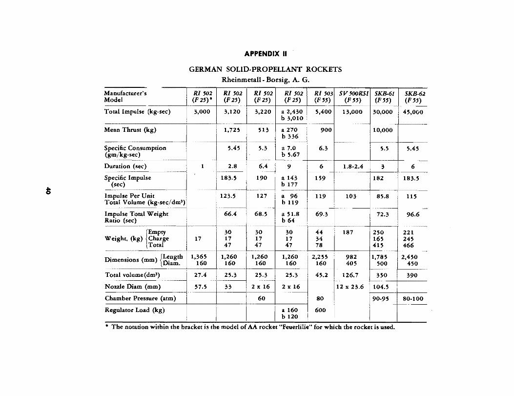
Manufacturer's Model
Total Impulse (kg-sec)
Mean Thrust (kg)
Specific Consumption (gm/kg-sec)
Duration (sec)
Specific Impulse (sec)
Impulse Per Unit Total Volume (kg-sec/dm3)
Impulse Total Weight Ratio (sec)
rmpty Weight, (kg) Charge
Total
Di . ( ) {Length menSlons mm Di am.
Total volume(dm3)
Nozzle Diam (mm)
Chamber Pressure (atm)
Regulator Load (kg)
APPENDIX II
GERMAN SOLID· PROPELLANT ROCKETS Rheinmetall· Borsig, A. G.
RI '02 RI '02 RI '02 RI '02 RI '03 SV500RSI (F25)* (F25) (F25) (F25) (F 55) (F55)
3,000 3,120 3,220 a 2,430 5,400 13,000 b 3,010
~~~-
1,725 513 a 270 900 b 336
~~~- ----------
5.45 5.3 a 7.0 6.3 b 5.67
1 2.8 6.4 9 6 1.8-2.4 ------- ~~~~~- ---------
183.5 190 a 143 159 b 177
123.5 127 a 96 119 103 b 119
~-t-~~~ ~-
66.4 68.5 a 51.8 69.3 b 64
--------
30 30 30 44 187 17 17 17 17 34
47 47 47 78
1,365 1,260 1,260 1,260 2,255 982 160 160 160 160 160 405
~~~- -----------
27.4 25.3 25.3 25.3 45.2 126.7 ------- ~~~~~~~~ -------
57.5 33 2 x 16 2 x 16 12 x 23.6
60 80 -----------
a 160 600 b 120
SKB·61 SKB·62 (F55) (F 55)
-~~~~~
30,000 45,000
10,000
5.5 5.45
3 6
182 183.5
~- -~~~~~~ ~-
85.8 115
---------- -72.3 96.6
250 221 165 245 415 466
~~~- f~~ -----------
1,785 2,450 500 450
350 390
104.5
90-95 80-100
• The notation within the bracket is the model of AA rocket "Feuerlilie" for which the rocket is used.
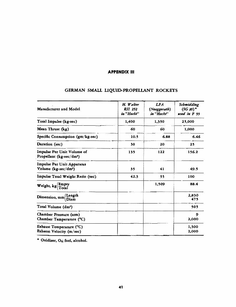
APPENDIX III
GERMAN SMALL LIQUIl)..PROPELLANT ROCKETS
H. Wllller I
LFA Schmidding Manufacturer and Model Rll 2'2 (Noeggerlllh) (SG 20)*
in "Hecht" in "Hecht" .sed ;" F "
Total Impulse (kg-sec) 1,400 1,350 25,000
Mean Thrust (kg) 60 60 1,000
Specific Consumption (gm/kg-sec) 10.5 6.88 6.46
Duration (sec) 30 20 25
Impulse Per Unit Volume of 135 122 156.2 Propellant (kg-sec/dm8)
Impulse Per Unit Apparatus Volume (kg-sec/dm3) 35 41 49.5
Impulse Total Weight Ratio (sec) 42.3 55 100
Weight, kg{i:~r 1,509 88.4
Di . {Length 2,830 menslon, mm n' 475 lam
Total Volume (dma) 505
Chamber Pressure (atm) 9 Chamber Temperature eC) 2,000
Exhaust Temperature (0C) 1,300 Exhaust Velocity (m/sec) 2,000
* Oxidizer, Os; fuel, alcohol.
41

APPENDIX IV
CODE NAMES OF LIQUID PROPELLANTS
The name of the institution which first suggested the code name, is given in abbreviation in the parenthesis.
(A) General Notation Monergol (LFM) Lithergol (LFM) Hypergol (LFM) Ergol (LFM) Tonka (BMW)
Initiator (HAP) Katagol
(B) ParticNlar Propellants Hypergol I (LFM) HypergollI (LFM)
Monergol A (LFM) Monergol B (LFM)
(C) Single Components 1. Oxidizer
Ignol (LFM) * Ignol98 (LFM) Ignol 98 KC4 (LFM)
Igno198 KN (LFM) Ignol 98 N (LFM) Ignol 98 NEN (LFM) Salbei (BMW) Salbeik (BMW) Salbeik C4 (LFM)
Salbiek C6 (LFM)
Salbiek N4 (LFM)
MS 10 (IG) T-Stoff (RLM) Ignotin (OKM) X-Stoff (HAP) V-Stoff (HAP) Hexal (LFA) XV-Stoff (HAP)
* Obsolete name.
- monopropellants - solid-liquid propellants - spontaneously inflammable bipropellants - the fuel component of the hypergol - the fuel component of the hypergol with concentrated
HNOa as oxidizer - the active component in ergols - gas generation by catalytic decomposition with catalyzer
in chamber
- Oxidizer, T-Sioff; fuel, hydrazine hydrate - Oxidizer, T-Stoff; fuel, a mixture of hydrazine
hydrate and methyl alcohol - Mixture of NH3 and N20 - Mixture of NH3 and NH~03
- highly concentrated nitric add - 98.0-98.2% HN03 + maximum 0.5% N20. - 96% by weight Ignol 98 + 4% by weight
FeCl3 • 6H20 - Ignol 98 + Fe (NOll)3 • 9H20 - Ignol 98 + N20. - Ignol 98 KN + N20. - high concentration nitric acid - high concentration nitric add with catalyzer - 96% by weight 98% HNOa + 4% by weight
FeCI, • 6H20 - 94 % by weight 98 % HNOa + 6 % by weight
FeCl3 • 6H20 - 96% by weight 98% HNOa + 4% by weight
Fe(NOa)3 • 9H20 - 10% H2S04 + 90% HN03
- concentrated H20 2
- concentrated H20t - Tetranitromethane .-N20. -N20. - 62% by weight X-Stoff + 38% by weight of
V-Stoff
42
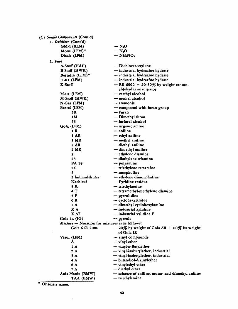
(C) Single ComJH»lenls (Cont'd) 1. Oxidizer (Cont'd)
GM-l (RLM) Mona (LFM)* Disab: (LFM)
-N,O -N,O -NH.NO.
2. Pilei A-Stoff (HAP) B-Stoff (HWK) Bertolin (LFM) * H-Ol (LFM) K-Stoff
- Dichloreacetylene - industrial hydruine hydrate - industrial hydruine hydrate - industrial hydruine hydrate - RB 6000 = 20-30% by weight croton-
aldehydes as initiator M-O 1 (LFM) - methyl alcohol M-Stoff (HWK) - methyl alcohol N-Gas (LFM) - ammonia Fantel (LFM) - compound with furan group
5R -Furan 1M - Dimethyl furan 5S - furfural alcohol
Gola (LFM) - organic amine 1 R - aniline 1 AR - ethyl aniline 1 MR - methyl aniline 2 AR - diethyl aniline 2 MR - dimethyl aniline 2 - ethylene diamine 23 - diethylene triamine PA 18 - polyamine 24 - triethylene tetramine 3 - morpholine 3 hohmolekular - ethylene dimorpholine Nachlauf - Pyridine residue 3 K - triethylamine 4 T - tetramethyl-methylene diamine 5 P - pyrrolidine 6 R - cyclohexylamine 7 A - dimethyl cyclohexylamine X A - industrial xylidine X AF - industrial xylidine F
Gola la (IG) - pyrrole Mixlllre - Notation for mixtures is as follows:
Gola 61R 2080 - 20% by weight of Gola 6R + 80% by weight
Visol (LFM) A lA 2A 3A 4A 6A 7A
Anis-Manie (BMW) TAA (BMW)
* Obsolete name.
of Gola IR - vinyl compounds .....:. vinyl ether - vinyl-n-Butylether - vinyl-isobutylether. industrial - vinyMsobutylether. industrial - butandiol-divinylether - vinylethyl ether - diethyl ether - mixture of aniline. mono- and dimethyl aniline - triethylamine
43
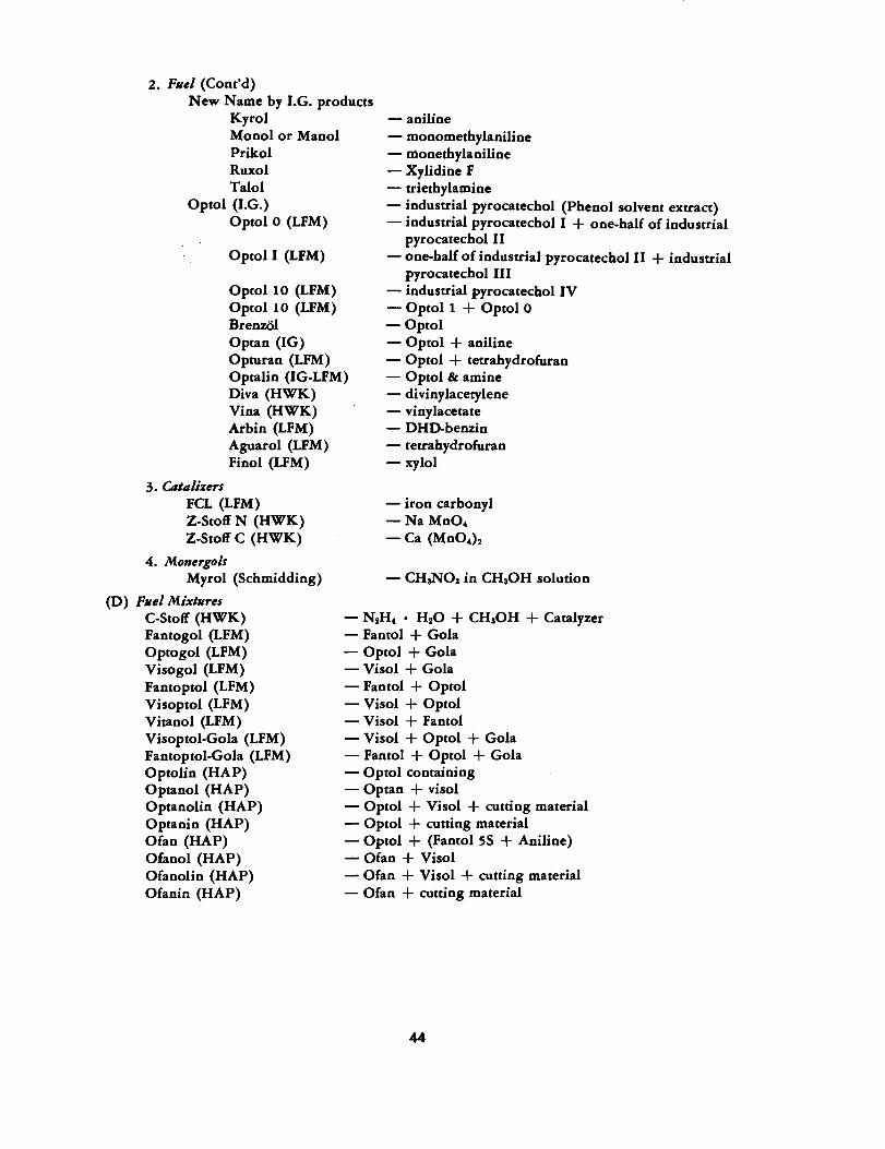
2. Fllel (Cont'd) New Name by I.G. products
Kyrol - aniline Monol or Manol Prikol Ruxol Talol
Optol (I.G.) Optol 0 (LFM)
Optol I (LFM)
Optol 10 (LFM) Optol 10 (LFM) BrenzOl
- monomethylaniline - monethylaniline - Xylidiile F - triethylamine - industrial pyrocatechol (Phenol solvent extract) - industrial pyrocatechol I + one-half of industrial
pyrocatechol II - one-half of industrial pyrocatechol II + industrial
pyrocatechol III - industrial pyrocatechol IV - Optol 1 + Optol 0 - Optol
Optan (IG) Opturan (LFM) Optalin (IG-LFM) Diva (HWK) Vina (HWK) Arbin (LFM) Aguarol (LFM) Finol (LFM)
- Optol + aniline - Optol + tetrahydrofuran - Optol & amine - divinylacetylene - vinylacetate - DHD-benzin - tetrahydrofuran - xylol
3. Catalizers FCL (LFM) Z-Stoff N (HWK) Z-Stoff C (HWK)
4. Monergols Myrol (Schmidding)
(D) Fllel Mixtllres C-Stoff (HWK) Fantogol (LFM) Optogol (LFM) Visogol (LFM) Fantoptol (LFM) Visoptol (LFM) Vitanol (LFM) Visoptol-Gola (LFM) Fantoptol-Gola (LFM) Optolin (HAP) Optanol (HAP) Optanolin (HAP) Optanin (HAP) Of an (HAP) Olanol (HAP) Of an olin (HAP) Of an in (HAP)
- iron carbonyl -NaMn04 - Ca (Mn04)2
- CHaN03 in CH30H solution
- N2H4 • H20 + CH30H + Catalyzer - Fantol + Gola - Optol + Gola - Vi sol + Gola - Fantol + Optol - Visol + Optol - Visol + Fantol - Visol + Optol + Gola - Fantol + Optol + Gola - Optol containing - Optan + visol - Optol + Vi sol + cutting material - Optol + cutting material - Optol + (Fantol 5S + Aniline) - Of an + Visol - Of an + Vi sol + cutting material - Of an + cutting material
44

PART II
HISTORICAL NOTES ON GERMAN GUIDED
MISSILE DEVELOPMENT
By
H.1. DRYDEN


PART II
HISTORICAL NOTES ON GERMAN GUIDED
MISSilE DEVELOPMENT
PC-l400-FX
This guided missile, the first to be used operationally by the Germans, is an aircraft-launched armor-piercing bomb with rudimentary wings which can be remotely controlled by radio along a trajectory which may be made to depart from a normal bomb trajectory by amounts of the orde.r of 500-1000 feet. The operator watches the bomb and target visually. The missile was used against ship targets.
According to the designer. Max Kramer, this development was started in November, 1939 at the Deutsche Versuchsanstalt ffit Luftfahrt, Berlin-Adlershof. The firm Rheinmetall-Borsig undertook the production and Kramer joined them. A brief account of this development was presented at a special meeting of the German Academy of Aeronautics on 5 November 1942. The first operational use of the missile was in August, 1943. The time required for its development was therefore 45 months.
Hs-293
This missile is an aircraft-launched glide bomb, accelerated by a liquid-fuel rocket for 12-15 seconds just after release. It is remotely controlled by radio by an operator in the releasing aircraft who watches the bomb visually. The missile was used against ship targets.
The designer was Herbert Wagner. He joined the Henschel Company at the suggestion of Dr. Lorenz of the Air Ministry and began the development of Hs-293 on 1 February 1940. The first successful tests were made at Peenemunde on 17 December 1940. The starting rocket was not used until the end of 1941. This missile was also described at the special meeting of the German Academy of Aeronautics on 5 November 1942. The first operational use was in October, 1943 and hence the time required for development was 44 months.
V-1,8-103
This missile is the well-known buzz bomb, a winged long-range seH-propelled missile launched either from the ground by a special catapult, or from an aircraft. It is used against large ground targets.
According to A. Busemann who was consultant to the German Air Ministry on the development contracts and Dr. Ing. Gunther Diedrich of the Argus Company, the history of V-I is as follows:
47

An inventor, Paul Schmidt, had a development contract from the Air Ministry for an intermittent jet motor in 1935. The work proceeded slowly. About November, 1939 Diedrick of the Argus Motor Company, who had been working for the Air Ministry on exhaust-pipe jet-propulsion nozzles, began work on intermittent combustion in an open pipe. In,1940, the Air Ministry brought Schmidt to the Argus Company and combined the developments. The first successful motor was completed in 1941, not, however, of the size used in V-I. Just when V-I itself was conceived and by whom is not entirely clear. Wagner stated that the Air Ministry told him in June, 1942, that work on long-range guided missiles would be resumed. The motor development itself was intended for use in aircraft. Busemann stated that when work on the V -2 rocket, a development of the ground forces, was delayed, Schel p, an assistant of Lorenz in the Air Ministry, proposed the use of a combination of small airplane with intermittent jet motor for the same purpose. The V-I is thus a development of the air forces. Its code name was originally "Kirschkern" (cherry pit) because it was merely to be spit out against England. Presumably Schelp's suggestion was made in 1941.
Fieseler Aircraft Company was selected to build the airframe. The development tests were made at the Air Ministry laboratory at the Luftforschungsanstalt Hermann Goring, Braunschweig, in the 2.8-m high-speed wind tunnel. The original model of the V-I was not very good, the net thrust of the motor being zero at 380 mph. About 60% of the time of this wind tunnel was used for nearly a year to bring the development to its present stage.
The first reconnaissance photograph of the V-I was taken by the British at Pennemo.nde in April, 1943, and Pennemo.nde was made uninhabitable by bombing in August, 1943. The first operational use was on 12 June 1944.
Busemann stated that the V designation originally meant simply Versuchsmuster (experimental type) and the interpretation as Vergeltungswaffe (vengeance weapon) was an afterthought of the SS propaganda groups.
V-2, A-4
The V-2 or long-range rocket was known as A-4 or Apparat 4 (apparatus No.4). According to Major General Dornberger, A-2, the first of the series actually launched, was fired in 1934 at Kummersdorf. It was a small rocket weighing about 3.30 lb with a thrust of about 660 lb.
The development of V-2 was due largely to the initiative of Captain (later Major General) Walter Dornberger, an officer of the Reichswehr and graduate as Dipl. Ing. of the Technische Hochschule, Berlin, in 1929, who was given an assignment to develop rockets for military purposes by Major General Becker in January, 1930. The scientific and technical leader of the group was Dr. Werner von Braun, who was taken directly from school in 1933, into the service of the War Department.
Dr. von Braun was a student of Professor Hermann Oberth, a well-known inventor and writer in the field of rockets who has published books on interplanetary rocket travel. A group of Oberth's students became interested in rockets and organized an amateur rocket group. All were well-trained scientists and considered by Dornberger to be the leading group. Dornberger obtained approval to work on liquidfuel rockets in 1932. All rocket development had been placed on the secret list as
48
early as 1931. The work was begun at Kummersdorf but the facilities there were found to be inadequate.
Dornberger then selected Peenemilnde because of the possibility of firing at distances up to 500 km along the coast with suitable observing stations. Construction was started in August, 1936, of facilities whose final cost amounted to 300,000 gold marks. In 1938, the designs known as A-3 and A-5 were constructed and fired. These weighed 1650 lb, had a thrust of 3300 lb and were equipped with rudders in the jet and automatic controls. The A-3 did not reach supersonic speeds but the A-5, the prototype model of A~4, reached a range of 18 km. While the A-4 had been ordered with specifications for a 1000-kg war head and a range of 250 km, hundreds of firings of the A-5 and much development testing from 1936 to 1942 were found to be necessary. In 1939, the priority ofthe A-4 was reduced and many civil employees were withdrawn from Peenemunde. Dorbnerger succeeded in getting 4000 soldiers from General von Brauchtisch and in having construction work done by Army engineers. The first successful range trial of the V-2 was on 3 October 1942. From this period to the middle of 1943, over 65,000 alterations in the drawings were found necessary to obtain a production version. Even in 1943 Dornberger stated that Hider wished to stop the project because he had dreamed that the V-2 would never fly.
In 1941, von Braun brought his former professor, Oberth, to Peenemunde as head of the patent section. By then Peenemunde was an active test station. The Me-163 was brought there in September, 1941 and in October, 1941 flew at a speed of 1003 km/ hr. In October, 1941, the first wind-tunnel tests were made on a projectile at a Mach number 4.4. After the bombing of Peenemiinde in August, 1943, the activities were decentralized. Dornberger claimed that the bombing only destroyed the settlement and that the evacuation was made because of the approach of the Russians. The move was made to various locations. The wind-tunnel group went to Kochel, where it was in operation in January, 1944.
The first operational use ofthe V-2 was on 8 September 1944. The Germans claim to have built 5400 and to have fired 3600 against the Allies. The first one is said to have cost 1,500,000 marks and the final cost was said to be 37,000 marks. The accuracy was stated to be 50% within an ll-mile square at 200 miles.
KRAMER'S LATER MISSILES, X-4 AND X-7
According to Kramer, the development of an air-to-air missile designated as 8-344 or X-4 was begun in June, 1943. This missile weighs 60 kg and is 1.9 m long. It has four sharply swept-back wings near the center of gravity and four tail fins. Aerodynamic control is by means of spoilers on the tail fins. Tabs on the wings cause the missile to spin. Two of the wings carry at the tips spools of fine wire 0.22 mm in diameter and long enough to permit a range of 5 km while maintaining direct wire connection to the control aircraft. A gyro-stabilized commutator in the missile and a suitable filter system, permit direct electrical transmission of the control from the operator to the spoilers on the control surfaces of the missile by means of the connecting wires, which can feed out at speeds of more than 200 m/ sec.
About 160 X-4 missiles were built and a document dated 11 January 1945 stated that 130 trials had been made. It was stated that the missile was in the early testing
49

stage to prove its fundamental correctness of functioning. At one time the Air Ministry had a requirement for 5000 by the middle of 1945 but this was later reduced. In February. 1945. SS leader Kammler ordered a lower priority and the closing cut of the project at the end of the development period.
Kramer designed an acoustic proximity fuse for this missile known as "Kranich." About 30 were built and some preliminary fly-over and fly-by tests were made. The effective range was expected to be 45 ft. The tests which had been completed were promising. Work was also under way to develop an acoustic homing device with a hoped for range of 500-1000 m.
The x-7 was a smaller edition of the X-4 for use against ground targets. Apparently it had not proceeded beyond the design stage.
WAGNER'S DEVELOPMENTS OF Hs-293 TYPE
Wagner stated that the original Hs-293 is more properly designated Hs-293A. Beginning also in 1940. a control using wires joining the missile to the mother airplane was developed to be used if the radio-controlled version was successfully jammed The wire-controlled version was known as Hs-293B.
Parallel with the Hs-293 development, Wagner designed a bomb to strike the water in front of a ship and then travel in a suitable underwater trajectory. The wing and tail systems were similar to Hs-293 but were notched to break off on impact with the water. The development moved slowly. having no great priority. but was ready in the early days of 1944. There were then no airplanes available to carry it. This development was designated Hs-294. A smaller version was known as Hs-293C.
Hs-295 and Hs-296 had the same fuselage as Hs-293 with general-purpose bomb and armor-piercing bomb as pay load. Hs-293D used television eqiupment. the first tests being made in the middle of 1942. A few tests were also made in 1944, but the television equipment was never completely satisfactory.
All glide bombs were abandoned for lack of planes to carry them. In May, 1941, Wagner proposed a ground-to-air rocket-propelled missile known at various times as 8-117, Hs-297, SI, and Schmetterling. A contract was not actually awarded until August, 1943. Work was started. however, in May, 1943 on this weapon and on an air-to-air weapon Hs-298. These developments were not completed. The starting weight of Hs-297 was 440 kg: its speed, M = 0.8, its final weight 175 kg. These missiles were to be controlled by direct radio control. On 22 January 1945, some 80 missiles had been tested, most with radio control. About half of these tested functioned properly. A scheme for control with tracking and a computer was under development. It was also planned to use some form of proximity fuse.
Some further details of Wagner's activities are given in USSTAF A-2 Technical Intelligence Reports 1-2 and 1-2a.
According to a P /W report series production of the Hs-11 7 began on a large scale in January, 1945 at an underground factory at Woftleben near Nordhausen in the Harz mountains which was controlled by the Henschel Company. Hs-298 was also being produced by Henschel (working under the code name Oder, AG) in a factory. in an underground railway at Berlin-Beukolln.
50
FURTHER V-l DEVELOPMENTS
There seems to have been ne concentrated and unified effort to make a better missile of the V·l type. There are a number of records of research on methods of cheapening the construction and usirig substitute materials for the control gyros and servos. There is a record of a meeting of the Armament Section of the Ministry for Armament and War Production in June, 1944 in which expected shortages of sheet metal and explosive for V.l were discussed. Finally in the German Emergency Develop. ment Program there were projects to use an Argus 014 aeropulse motor and also a Persche 005 tubojet motor in the V-l airframe to increase its range. The Argus 014 is an aeropulse with improved altitude performance and life and the Persche 005 is a simple and cheap turbojet of low· grade materials.
The Deutsche Forschungsanstalt ftir Segelflug had a number of projects on the aeropulse motor, including one airplane, Me-328, using the aeropulse motor for propulsion. This airplane was to be used for thrust measurements in flight at high speeds. It was stated that these results must be obtained to be able to determine the maximum range and velocity of FZG·76. FZG.76, 8·103, Fi·l03 and V-l are all desig. nations of the V·l missile. This statement was made on 31 March 1944.
FUl fHER V-2 DEVELOPMENTS
The later developments of A.4, the German designation of V.2, were A.6, A.7, A·8, A·9, A.I0, and C·2, also called Wasserfall. As previously noted, A·5 was a small· scale A-4 used for experimental purposes in the development of A.4 and was designed and constructed before A·4. A·6 was a design study, never constructed. A· 7 was a design study of A· 5 with wings intended for launching from aircraft to secure scientific data. A·8 was a design study, never built, of A·4 with wings. A·9 was the most recent design of A·4 with wings. It was computed that the use of wings would increase the range of A·4 to about 400 miles. A·I0 was a launching rocket to be used with A·9 to secure ranges of 3000 miles. The total weight of A·l 0 was 190,000 lb of which about 140,000 lb was fuel. Its thrust was 440,000 lb for 50 sec. It was nearly 12 ft in diameter and 25ft long. The 29,000.lb A·9 was to be accelerated to a speed of 3600 ftl sec by the use of the 190,000·lb A.I0 as launching rocket. The rocket motor of A'9 would then be turned on and increase the speed to 8600 ftl sec. The explosive load would be about 1 % of the starting weight. Some consideration was also given to carrying a pilot in the A·9 rocket.
The A·tO was on1y a project on which some drawings and computations had been made. A .few experimental A·9's were .constructed but there is every evidence that no actual firings were made. Interviews with General Dornberger, Dr. von Braun, and others confirm this statement and there is further evidence. In a report of t 5 March 1945, Dr. Kurzweg, ad'odynamicist of the Peenemtinde wind·tunnel group, states in recounting the story of the development of WasserfalI that the basic shape of A·4 was selected for VVasserfall because of previous experience. He states further that the group has "some experience but only in the wind tunnel on a glider model which was a further development of A-4."
51

WASSERFALL
Beginning in early 1943 (one source gives September, 1942 as the starting date), the entire resources of the Peenemunde group were concentrated on the development of an antiaircraft guided rocket first designated C-2 and later Wasserfall. The first experimentatfi..ring was made on 28 February 1944. By January, 1945, 25 experimental firings had been made, all but one with radio control. Fifteen of the firings gave satisfactory flight.
The Wasserfall missile is.88 cm in diameter, 783 cm long, has a launching weight of 3570 kg, and a final weight of 1615 kg with pay load of 305 kg of explosive. It is rocket propelled for 45 sec with a liquid-fuel rocket of 8000-kg thrust. The maximum speed is about 770 m/sec and its maximum height 18.3 km. The horizontal range is 26.5 km.
The control method was designated "Rheinland" which was to be developed in four stages. In the first stage, the rocket was to be steered by direct radio control according to the eclipse procedure as used for FX1400 and Hs-293 with the aid of optical two-axis tracking apparatus. The Kehl-Strasburg meter-wave control transmitter was to be used. At night searchlight beams were to be used. So far as known at present the tests completed were made with this equipment.
The second stage used radar tracking of missile and target with a suitable visual presentation. A human operator was still used with radio transmission of the control information.
The third stage was the automatic control, the radar-tracking device being coupled through a suitable computer to the control stick.
The fourth stage was beam guiding with a homing device for the final stage of the trajectory.
According to one report (unpublished and unfinished manuscript on "Systems of Beam Guiding" found at LFA Braunschweig), dated 28 March 1945, it had been determined by the Peenemunde group that the control described as the second stage above could not be carried out because of the slowness of the human brain and that therefore the control signals must be formed electrically and transmitted automatically to the missile.
The Peenemunde group developed an infrared proximity fuse for use with Wasserfall.
The history of the aerodynamic development of Wasserfall is given in a report WV A 171 by Dr. Kurzweg entitled "The Aerodynamic Development of the Flak Rocket Wasserfall." This interesting document brings out the fact that Wasserfall was, in addition to its immediate application, a contribution to the aerodynamic development of the long-range winged rocket. More than 25 designs were tested in the supersonic wind tunnel at speeds up to three times the speed of sound. The lift-drag ratio was 4.15 at low speeds, 4.42 at Mach number 0.6, 3.90 at Mach number 0.84, 2.90 at Mach number 2.90.
No data are available to the writer on the production plans for Wasserfall. On 6 February 1945 the SS leader Kammler who had been given authority over the develop-
S2
ment of guided missiles stated that the Wasserfall project would be closed out at the end of the development period, priority being give~ to unguided rockets such asTajfun.
RHEINTOCHTER
This missile is an antiaircraft rocket developed by Rheinmetall.Borsig, one of three similar developments sponsored by Halder of GL Flak E5, the others being Wasserfall and Enzian. The first experiments with steering were made in February, 1944. According to one report Rheintochter was abandoned in favor of Hs-ll 7 after a demonstration to Goering and Speer at K.arlshagen in October, 1944. On 6 February 1945, SS leader Kammler stated that Rheintochter was to be closed out at once.
Rheintochter had a diameter of 53.6 cm, a length of 500 cm, a starting weight of 1570 kg, final weight of 685 kg, with a pay load of 160 kg of explosive. Its maximum speed was 410 m/sec, maximum height 15.2 km, range 18.9 km. It was launched with powder rockets. On 22January 1945, 82 tests had been made, 39 without control, 21 with preset program of control, and 22 with radio control. Fifty.six functioned satisfactorily.
ENZIAN
This is the third AA rocket sponsored by GL Flak E5. It was designed by Dr. Wurster, chief test pilot of Messerschmitt and holder of the 1936 world's speed rec· ord in the Me·109. The development was begun in November, 1943. Work was interrupted by the destruction of the Messerschmitt plant at Augsburg in February, 1944. The project was moved to Sonthofen and later to Schlosswirtschaft Linderhof near Oberammergau. A document dated 22 January 1945, said that 23 missiles had been launched, all without control, and that 14 were failures.
On 24 February 1945, the aerodynamics man Neuschutz wrote in an internal memorandum, "for the further work a clear leadership must be created with definition of responsibility. Dr. Wurster, Dr. Thiel. Dr. Thun, and Mr. Muhlberg now have some authoritative influence without a plan of organization and without a leader. The previous lack of success does not lie in the technical sector but is solely in question of leadership.
"No information on aerodynamic and flight performance has been obtained from the test firings because the firings were marred by explosions, failures of launching rockets. etc."
The work was ordered stopped on 17 January 1945. Messerschmitt intervened and took the matter to Hider himself but the work was finally stopped about the middle of March.
There were several designs of Enzian. The subsonic version was similar in design to the Me-163 airplane which has no horizontal tail surface. It was 90 cm in diameter, 365 cm long, starting weight 1600 kg, final weight 690 kg with pay load of 300 kg of explosive. Its maximum speed was about 270 m/ sec, maximum altitude 13.8 km, range 2S.3 km.
In the tests a conventional radio control was used. It was intended to use an acoustic homing device or an infrared homing device.
A larger supersonic version with pay load of500 kg was also designed.
53

HECHT FEUERLILIE
The LF A Braunschweig had a development program on a glide bomb, Hecht, and on ~ flak rocket, Feuerlilie, which moved very slowly. The glide bomb Hecht was developed in the period from early 1940 to late 1941. A few drops were made but nothing came of the development.
The work on Feuer1ilie began in early 1942, was given high priority in early 1943, stopped late in 1943, later revived, and again stopped in early 1945. Three models of smaller size, designed F-25 were fired in May, 1944, and one ofthe intended size F.55 was fired also in M$.y, 1944. Much theoretical work was done on the theory of homing missiles and the theory of beam-guided missiles. The actual tests made were not very satisfactory .
The LFA was finally instructed to use Enzian or Schmetterling for its beam-guiding experiments but no such experiments were actually made. .
The Feuerli1ie weighed 600 kg and had a maximum speed of about 422 m/sec. Its maximum altitude was about 8 km. It was 55 em in diameter and 480 cm'long.
This project suffered because of lack of support by an industrial group. Two statements by Blenk, director of the LF A, which were made in 1942, illustrate the situation. Reporting on missile research in Germany in 1942, he says: "Work is in progress on remote-controlled bombs in Germany in various places in industry and in aeronautical research laboratories. In spite of the many-faceted aspects of the problem it is desirable that the experiences collected in these projects should come to the knowledge of all agencies active in this field more quickly and completely than hitherto. In this the communication of negative results is especially important since much time would be saved thereby.
"While industry is capable of making rapid progress in these problems because of their large workshops, the research laboratories must take up ever slower negotiations with industrial firms to have their designs constructed at least in a few samples and to test them. Here some support is to be desired for the more rapid completion of such jobs."
In a report on the LFA guided.missile research in 1942, Blenk states that he, Braun, Kerris,. and Retert had been working on an air-to-ground rocket-propelled remote-controlled missile since the beginning of the war and on a ground-to-air rocket-propelled remote-controlled missile for about one year. He said that numerous problems were encountered, for example:
(1) Necessity of automatic stabilization in roll.
(2) Suppression of the phugoid motion.
(3) Influence of jet propulsion on the flight characteristics.
(4) Stability at extreme inclination of flight path.
(5) Development of suitable antennas.
(6) Influence of jet on radio receiver.
54

NATTER
The Natter project, while not an unmanned guided missile, should be mentioned. It is a manned rocket-propelled interceptor airplane armed with 24 rockets of 7.3-em caliber. The airplane was intended to be launched nearly vertically by means of two or four solid-propellant launching rockets toward a point about 2 km behind the point of collision so that attack on a bomber could be made from the rear. A steel plate ahead of the pilot served as armor plate and as a deflector of the exhaust from the rocket projectiles. After the rocket ammunition is exhausted, the airplane is caused to disintegrate, the nose section allowed to fall freely and be expended but the airframe with rocket-propulsion motor and the pilot are saved by parachutes.
The propulsion motor is the Walter rocket motor used in the Me-163 and by using this already developed motor, the Natter project could proceed very rapidly. The project was originated by Bachem and the chief designer was Willy Fiedler, formerly chief test pilot of Fieseler. Actual work was started on the project in October or November of 1944, and the project was well advanced when Germany fell.
HOMING DEVICES
At a meeting of the German Academy of Aeronautics devoted to Special Problems of Remote Control on 5 November 1942, there was one paper on homing devices for missiles by Edgar Kutzcher entitled "Infrared Equipment for Target-Seeking Apparatus." Many laboratory projects on homing devices were authorized by various agencies from this time until the end of the war. The Minister for Armament and War Production, Speer, in July, 1944, created a number of agencies to review research and development programs and establish priorities. One of these agencies was the Main Electrotechnical Committee which established a Special Committee on Electrical Components of Munitions under the chairmanship of Dr. Gladenbeck, who had previously been associated with the Forschungsanstalt der Reichspost. A subcommittee of this Special Committee, headed by Dr. Runge, covered the field of proximity fuses and homing devices. A survey by this subcommittee showed 25 projects for homing devices, of which eight were acoustic, nine infrared, two optical, and six radio or radar methods. The list is included in Appendix I to this report. Three of these were infrared devices under development by Dr. Kutzcher for which the developments in two instances were said to be nearly completed as of 15 August 1944.
Appendix II contains extracts from the minutes of the Gladenbeck committee. A reading of these minutes and of various other documents leads to the conclusion that none of these devices were out of the laboratory stage and that the development of homing devices lagged considerably behind the development of vehicles and their propulsion.
MISSILE ACTIVITIES OF THE AERONAUTICAL RESEARCH INSTITUTIONS
The aeronautical research institutions gave a great deal of attention to missile problems by conducting wind-tunnel tests and making many theoretical investigations. The Deutsche Versuchsanstalt fur Luftfahrt, Berlin, (DVL) was largely active in the development of the FX and made at least one series of measurements on HS-293 and on V-I. The Aerodynamische Versuchsanstalt Gottingen (AVA) made wind-tunnel
55

measurements on Rheintochter, HS-117, Zitterrocken, and on long-range rockets. The Luftfahrtforschungsanstalt Hermann Goring, Braunschweig, (LFA) made aerodynamic measurements on glide bombs, did the major wind-tunnel work on the V-I aeropulse motor, undertook the project Feuerlilie already described, and did considerable work on the theory of stability and control of missiles, especially homing and beam-guided missiles.
One of the key groups in the missile developments of the German Air Force was the Deutsche Forschungsanstalt fUr Segelflug. To illustrate the large part played by missiles in the program of the institution an abstract of the DFS progress report for the period 1 December 1943 to 31 March 1944 is attached as Appendix III. One important contribution of this group was the development of equipment for simulating missile flights which permitted tests of different control systems and the training of pilots in remote control.
An incomplete bibliography of reports from these and other institutions on guided missiles is attached as Appendix IV.
THE DREAMERS AND PROMOTERS Mention has already been made of Professor Hermann Oberth and the part played
by this high school professor iti stirring the imaginations of the young engineers who later developed the V-2. His early activities in cooperating with UFA in making the motion picture "Lady in the Moon" with its space rocket sequence and his two books, "The Path to Space Ship Travel," and "By Rocket to the Planetary Regions," are perhaps sufficient to clarify his personality. Oberth did considerable puttering in the laboratory and made many sketches and patent drawings of very large rockets. His pupil, Dr. von Braun, took him to Peenemiinde as head of the patent section. While there he studied the design of a long-range rocket to travel 6000 km. He decided it could be made with present materials but that it was not practical, since 96 tons starting weight would be required for each ton of useful load, even though the step-rocket principle was used. .
A man with somewhat better engineering training but of the "promoter" type is Professor E. Sanger who was, at the end of the war, active at the DFS in the Division of Special Propulsive Devices. From 1937 to 1944, Dr. Sanger was in charge of a large rocket-research station at Trauen near Fassburg operated under the direction of Busemann of the LF A at Braunschweig. Sanger had planned this station for the study of high-velocity high-temperature rockets. He had grandiose plans and wished to develop a 100-ton rocket. The engineers at the LFA found Sanger's measurements unreliable and his engineering in their opinion incompetent. Sanger left after a quarrel in 1944.
Sanger wrote another volume to his well-known book on rockets in which he discussed the pro blem of bom bing New York City from bases in Europe. The accounts in the book are considerably in advance of actual technical accomplishments in Germany, yet not in error as to the possibilities of future development. The more conservative engineers of the Peenemiinde group (such people as Dr. Oberth and, of course, Dr. von Braun who is a good salesman for his group and does not always present the distinctions between foreseea ble scientific development and fancy) agree that sufficient information is available to permit the development of a transoceanic rocket within a period of from three to five years, if such an accomplishment is deemed worth-while.
56

APPENDIX I
GERMAN PROJECTS ON HOMING DEVICES, STATED TO BE IN PROGRESS 15 AUGUST 1944
I. ACOUSTIC
1. Dogge, Dr. Benecke; Messerschmitt, Hollein and Telefunken, Elac. Four microphone sondes, 4-phase true amplifiers, 12-16 tubes, 2-phase meters with bolometer amplifier. Range over 350 m with Me-262 units. 40% developed.
Note: On 25 January 1945 the 0 series was said to be under construction. Intended for X-4 missile.
2. Luchs, Dr. Hecht; Elektroakustic, Kiel. Phase measurement, 12 tubes, 2-phase relays, range 1.5·2 km, weight 15-20 kg. 60% developed.
3. Pudel, Dr. Kramer; Ruhrstahl. Directional head, amplitude differences, 4 resonance mem-branes, 2-3 tubes, range 500-1000 m, projected for X-4 missile.
4. . ... Dr. Trage; Reichspost. Phase difference, 4 microphones, projected for Rheintochter.
5. XX" Dr. Schops; RPF Wurzburg. No information.
6. . ..• Prof. Kussner; A VA Gottingen. No information.
Note: Believe Kussner did only theoretical work on acoustic homing.
7. Prof. Lubke; Braunschweig. No information.
8. . ... Dr. Heymann; Darmstadt. No information.
II. INFRARED
9. Hamburg 1, Dr. Kutzcher; Elektroakustic, Namslau. Mirror 25 em diam. 7 tubes, weighs 20 kg, range 3 km against ships, development nearly completed.
10. Armin 2, Dr. Kutzcherj Elektroakustic, Namslau. Television-type scanning, proportional indication, 1200-1500 m against He-lll, 11 tubes, 45° field, development almost completed.
11. Hamburg 11, Dr. Kutzcher; Elektroakustic, Namslau. Wide-angle objective, 7 tubes, 1000 m against large ships, 20° field. in process of development.
12. GlNhwurmchen, Obering Drenkelford; Rheinmetall, Breslau. Optical lens, spiral scanning, 8° field or 3° field, weight 3 kg, 3 samples available, production of 50 in hand for GL Flak E.
13. . ... Baron Pfeiffer; Kepka, Wien. Mirror 28 cm diam, 5 tubes, range probably 3000 m, 18° field reducing to 1_1/2° on picking up target, preproduction run of 50 samples. Note: 0 series probably under construction in January, 1945.
14. Netzh~ut, Krebs, Dr. Orthuber; AEG. Lens' system with scanning, on-off control, 700 m against He-i 11,8° field with 4.5-cm optical system, 3 tubes, photocell, in develop· ment.
15. Widder, Dr. Hilgers; AEG Research Laboratory. Two systems in development with 3 tubes and thyraton.
57
16. Linse, Dr. Kober; Gema, Berlin. Mirror system with Schwarzchild comparison system, 3 tubes, electric cell for control in 1 coordinate, completed. Control in 2 coordinates under development.
17. . ... Dr. Menke; Physical Laboratory Zappat. Same as (12) (Gluhwurmchen) but combined electrical and mechanical scanning, 5-6 tubes, weight 3.4 kg, 5 ° field.
III. OPTICAL
18. Pinsel, Dr. Rambauske; Ges. f. Forschung und Entwicklung. Iconoscope, spiral scan, rectilinear coordinates, 2000 m, 20° field, 8 tubes, midget iconoscope, directing device for iconoscope, prototype available.
19. . ....... Dr. Himmler; DVL (RRG). Similar to (15) Widder.
IV. ELECTRICAL
20. Windhlmd, Dr. Gross; RPF. Passive type, receiver for Naxos Z, full automatic switching, range of a few km, 25° field, stielstrahler, probably 5 tubes, to be used against Rotterdam or Meddo-birat apparatus.
21. Radieschen, Dr. Brtickmannj RPF. Passive type, direction finding on Poynting vector, range 80-100 km for 1 kw transmitter, 10° field for continuous control, gives onoff for 90°, Strassburg receiver with additional LF stage. Present weight 10-12 kg for search head, 5 kg for receiver and converter. A few V samples available for testing with FX missile.
22. Licht, or Moritz, Dr. Pressler; RDF, DPR. Active type, radar transmitter external to projectile, receiver only in missile. Range 1000-2000 m, 9-11 tubes, "bugs" being taken out.
23. Blalllicht, Dr. Heymann; RPF. Similar to "Licht" but shorter waves. Has 9-11 tubes, range 1000-2000 m, "bugs" being taken out.
24. Dackel, Dr. v. Octingen; RPF. Active type, complete radar. Good range resolution at short ranges, 50 m, (back edge of impulse). Range estimated as 1000 m, 20° field, 12 controlled tubes, 2 diodes, weight 3·4 kg without battery. Laboratory sample under construction.
25. Max, Dr. Gtillner; Blaupunkt Werke. Active type, CW transmitter decoupling by Doppler effect. Range expected 500 m, 15° field, 10 tubes, magnetron. Development just begun.
Notes: RPF is "Forschungsanstalt der Deutschen Reichspost."
Gladenbeck Committee, 13 September 1944 mentions I, 16, 18,20. 21, 22, 23, 24, 25 and two not identified.
Gladenbeck Committee, 8 November 1944 mentions 1,2,9, II, 16, 18,22, 24 and one not identified.
Document of 29 January 1945 states that "the work of the Gladenbeck Committee on target.seeking devices has not yet led to a successful conclusion. In some places the impression appears to prevail that it would be preferable if the Gladenbeck Committee worked with a greater concentration:'
58
APPENDIX II
Extracts relating to development of homing devices for guided missiles taken from the minutes af the Special CommiHee on Electrical Components
of Munitions (Gladenbeck CommiHee) of the German Ministry far Armament and War Production (Speer Ministry),
Meeting of 13 September 1944
Professor Gladenbeck in an introductory statement explained that the session was for the purpose of reporting on the previous work of the Special Committee on Electrical Components of Munitions. At the same time he requested the representatives of the using services to make known their present wishes as to the decisions made by the committee and already discussed with them. Profressor Gladenbeck stated further that the work of the special committee covered the three fields, proximity fuses, homing devices, and control devices (servos, etc.). The first task consisted in making a survey within the committee of the individual development projects. Finally after thorough consideration, a consolidation or elimination of a great number of the develo.pments found to be in progress will be made in order to arrive in this manner at a determination of the most important principles (Schwerpunktbild.ung, literally, formation of the cen· ter of gravity). It is assumed that the survey of the individual developments is almost completed. For the case of proximity fuses the special representative for fuse questions in the munitions committee, Major General Heydenreich, has carried out a similar survey and has arrived at approximately the same number of developments in progress. The limitation of developments has been carried out in such a manner that nothing essential has been lost. In the further conduct of the development, those development agencies, in general, have been supported with approximately the same number of proposals whose developments have progressed the furthest. Greatest priority has been given to aircraft rockets. Work in this field can be carried out with special acceleration since Minister Speer has designated Professor Gladenbeck as his special representative for the development of a complete air-to-air rocket.
Prof. Gladenbeck named the chairman of the individual subcommittees as follows:
For proximity fuses and homing devices, Dr. Runge;
For stabilization and control, Dr. Hilgers;
As liaison officer for electrical power supplies, Dip!. Ing. Bohm.
Then Dr. Runge reported on the work of his committee.
* * * * * (Discussion of proximity fuse developments.)
* * * * * Dr. Runge then reported on the concentration of developments of homing devices which had
been accomplished.
In the acoustic field there had been developed a unit device, at first for the X-4 missile. A working partnership had been organized under the direction of Dr. Benecke. The development work was being done by Dr. Benecke and fundamental investigations in the Physikalische-Technische Reichsanstalt by Dr. Grtitzmacher at Warmbrunn. The unit homing apparatus contained fQur microphones, and two measurements of phase were made for the vertical and lateral errors.
59
The available types of microphones had been measured by the P. T .R. The result was that the A VA microphone which depends on the cooling of a bolometer wire by the sound was by far the most favorable. It had the greatest sensitivity and the greatest freedom from disturbance by vibration.
In the optical field, two types were developed, one for reflective optics, the other for refractive optics. For marine purposes the development "Unse" (control in one plane) also is in progress.
Independent of these developments, Dr. Rambauske is working on the development of apparatus on the principle of the iconoscope (use of variations in brightness produced by a target). It is still to be clarified whether the iconoscope can be manufactured in the required quantity.
In the electrical field there are, in all, ~ix developments in progress, five at the Post Office Research Laboratory and one at the company, Blaupunkt. Two passive devices (receiver only) are provided for attack on Rotu~rdam installations (code name W'indhund) and for attack against ground targets, for example enemy radar installations (code name Radieschen). For the two active devices "Dackel" and "Max," only studies are in progress at the present time. In the pulse type "Dackel" the problem of the close-up resolution is especially to be solved, while the device "Max," which operates with continuous waves and Doppler effect, ground reflections will probably cause difficulty. The last two developments are to be designated as semipassive, since the transmitter is outside the missile. For these two developments also, only studies are in progress at the present time.
The following discussion results from the presentation of homing developments by Dr. Runge:
Professor Gladenbeck. These developments are still p~oceeding along very broad lines since fundamental questions have not been clarified.
OberbauratJohannson. In what stage is the development "Pinsel" of Dr. Rambauske?
Dr. Runge. At present it is not dear what Rambauske can offer in the way of contrast; besides there are difficulties in the manufacture of a sufficient number of iconoscopes. A further demonstration will be given by Rambauske at the end of September.
Chief Staff Engineer Bree. The experiments which have been made with "Tonne" against sea targets leave no exciting expectations for ground-target use since there the contrast will be still worse.
Staff Engineer lmmelen. S-ince there is no interest from the tactical point of view the OKL chief of TLR/E4 has not renewed the development contract for the passive apparatus "Radieschen. "
Professor Gledenbeck. That is a pity, since this is the most advanced development of electrical homing apparatus.
Dr. Luschen. If E4 has no interest in the further support of the Radieschen development, the special committee can recommend its continuance if considered necessary.
Finally Dr. Hilgers reported on the work of the subcommittee on remote control and stabilization. The work of this subcommittee began somewhat later than that of the other subcommittee so that a deciSion as to the relative importance had not yet been made.
The work of the subcommittee is divided into three parts:
(1) Unification of the controls and servomotors for flying bombs, torpedoes, and gliders.
(2) Standardization of electrical circuits on flying bombs.
(3) Cultivation of a project relating to the connection of homing devices to the controls, especially of glide bombs and pursuit devices.
On the first point it may be stated that today three kinds of controls are to be distinguished, namely, the pure electric, the pneumatic in which the control surface position is correlated to that of the transmitter, and those controls in which the control mechanism consists only of mag-
60
nets which act on the control surface itself with full deflection. The last named type presupposes control projections or spoilers as the control surface. A unification of these systems is to be earnestly attempted with respect to questions of manufacture, thrust, and material. The pneumatic control mechanisms have the advantage of small time constants and large forces with the fault of no saving of material. Electrical controls have an advantage, the single circuit, the freedom from temperature effects, as well as the advantage of not having to convert from electrical to pneumatic circuits. If one uses only magnets as control mechanism, this type represents without doubt the simplest and cheapest form. It requires special controls, however, which are not always applicable.
On the second point it may be stated that the circuits usually have two voltages, a 24-volt and a high-voltage side. The 24-volt circuit is supplied either by storage batteries or by a generator driven by a propeller, in turn driven by the relative wind.
On the high-voltage side, current for driving various amplifiers is supplied by plate batteries, transformers, or from a wind-driven generator. From the standpoint of insulation, high-frequency techniques, and load carrying capacity a simplification of the electrical circuits is to be attempted with special attention to the factors just mentioned.
On point (3) it may be stated that the question here is one of working out a project. The connection of homing devices to the controls of a missile is a problem which presents a very large number of difficulties. Until now connections of homing devices to controls have been project.:!d by various groups but not yet carried out or practically tested. The subcommittee has therefore considered its most important task to be that of realizing such a combination with the greatest speed. Therefore, at the suggestion of the subcommittee, several homing devices have been developed, which will be completed at the end of this month and which are for the purpose of studying the control network. These devices which are equipped at first with caesium cells, are the forerunners of pure infrared devices with Elac cells and are so shaped that after successful drops of the first missile infrared equipment can be installed. The subcommittee hopes that by the middle of next month the first complete control will be demonstrated in which the Henschel airframe Hs-293 will be used with respect to attacks on ships.
In the discussion, Director Wilde inquired whether it would not be better to conduct the first experiments with airplanes instead of with missiles. Dr. Hilgers remarked that such proposals had already been made but that the decision had been made against this procedure, because the relationships in gliders would give quite a different picture because of their low speed and in powered flight additional complications arise from the very large mechanical and acoustical vibrations and also the mechanics of flight of aircraft are quite different for airplanes as compared to rocket-driven bombs. Staff Engineer Immelen asked about the conduct of the experiment and with regard to the connection of the devices on two- and four-finned missiles (airplanes and bomb-like missiles), which were answered in detail by Dr. Hilgers, that the first devices were provided for "one day" experiments to simplify the testing and to decrease the fuel consumption. With regard to connecting the devices, it was mentioned that the connection of homing devices to bomb-like missiles was fundamentally the simpler technical problem, that, however, with the larger number of existing airplane-like missiles one must immediately attack this problem, especially since at present no bomb-like missile was available for immediate tests, if one disregarded the very heavy Fritz-X which could only be released at high altitude. Obviously the development of homing devices had to consider this device also in order to be able to connect to this device in its final stage as well as to X-4 in the first instance.
* * * * * (Then followed a discussion of power requirements, batteries, etc.)
* * * * * 61

Meeting of 8 November 1944
Professor Gladenbeck introduced Dr. Weiss, who had accepted the chairmanship of the subcommittee on countermeasures against enemy homing devices. Dr. Weiss requested the servic~s and the Army in particular to put at his disposal as quickly as possible all material on enemy devIces. Reports are to be made to the office of the Special Committee on Electrical Components of Munitions. Professor Kupfmuller requested cooperation in this question with the Central Office of Technical R~dio Information, Dr. Bode (plenipotentiary for high frequency).
* * * * * (Dr. Runge reported on proximity fuses.)
* * * * * DR. RUNGE'S REPORT ON HOMING DEVICES
The development "Dogge" (acoustic) was undertaken for the X-4 missile. It is planned to cut off the propulsion after a certain time of flight. Dr. Benecke showed a microphone with a built-in amplifier. For X-4 (a missile with rotation) two such microphones are used which are installed diametrically opposite each other. Telefunken-Messerscbmitt microphones are used. It is hoped to obtain ranges of about 1000 m. In addition to "Dogge" there is a further development "Luchs." The error signals are obtained by periodic switching. In this way there is a saving of tubes. General measurements are in progress at Elac by Dr. Hecht. On this side there are favorable results of measurements on microphones which, however, are subject to reservations. Dipl. Ing. Muck is working on a third acoustic development.
The development of electrical homing devices lies essentially in the hands of the Post Office Research Department. Of these developments the device "Moritz" works with the interference field which is found around a target illuminated by a stationary CW transmitter. The error information is obtained from the midpoint of the interference field. The preliminary testing has given good results. In addition there is in progress among these a pulse device, which, however, has not advanced as far.
Of optical homing devices, the first to be named is the device "Linse," whose range against various sea targets has been tested as 1800 m. The angle of view is ± 10°. At present, the device lacks seaworthiness. The conversion of the output of the device to control signals has been solved by the firm Askania. An attempt is being made to increase the field of view without limiting the range. In addition, the rotational speed of the scanner will be increased.
Besides the current developments "Emden" and "Hamburg" on whose manner of operation Dr. Kutzcher reported separately, two additional optical developments or contracts had been awarded in the interim to Askania and LGW. While in the meantime it has been determined, with respect to the LGW contract, that these ideas have already been considered in existing developments, no further data are available as to the current development at Askania.
Further experiments are in progress on the development "Pinsel." In the discussion on homing devices Staff Engineer Bree called attention to the bad rotational characteristics of X-4 with regard to the "Dogge" device. According to the previous experiments the rotational frequency varies between 4 and 1 or finally even to 1/2. It has been determined that a rotational frequency of 4 is most desirable. To a question on power requirements Dr. Benecke gave the total consumption of the "Dogge" device as 25 w. A suitable battery is available.
In connection with electrical homing devices the "chaff" question was discussed. According to the view of Bree the continuous jamming of air-launched devices by "chaff" was much more difficult than of ground-launched. Bree recommended, therefore, that the transmitter be placed on an airplane. Against this, Dr. Runge pointed out that then ground reflections came into the picture in a disturbing way. Professor Kiipfmiiller suggested that experiments also be made with "lY"~ritz" against sea targets.
62

Oberpostrat Weiss called attention to a contract of Chief Staff Engineer Gromoll who con. sidered a simple television apparatus (about seven tubes) as possible for flak rockets. Simplification should obviously be possible by.producing the synchronization by the radar method.
Professor KUpfmUller made a proposal to use Rambauske's device and similar tracking devices as target-indicating devices.
* * * * * (Discussion of tubes, fuse safety devices, etc.)
* * * * * DR. HILGER'S REPORT OF THE WORK OF THE SUBCOMMITTEE ON STABILIZATION
AND CONTROL
The work of the committee has related to the survey of existing and projected controls and on working out a project for the connection of target-seeking devices to the controls of missiles.
With regard to unification of controls, Chief Engineer Thiry had made invesitgations which have been assembled into a special report. These investigations relate to the status of present developments and show the satisfactory result that the development of apparatus in this field has progressed so far that almost any regulating task can be practically solved today with existing methods.
To the question raised at the last meeting whether electrical or pneumatic or hydraulic control mechanisms are most suitable, the report gives a statistical review. It likewise contains valuable compilations of the missiles provided with course steering, twO- and three-axis controls.
With respect to the connection ~f homing devices to the control of glide bombs, Dr. Hilgers showed an optical homing device developed by AEG, which serves as a starr for testing of controls. This has been completely developed for the manufacture of a small series and has for a field of view of ± 20° a range of 3 km or more by day and a light source located on the ground. The device is so developed that it can give tracking in Cartesian and polar coordinates and shows excellent characteristics for testing controls with a sensitivity of ±0.1° to ±O.lSo.
In general, for the test of homing devices, in accordance with the report at the last meeting, a ground-launched missile has been developed and built (code name "Steingeis," later changed to "Springback"). Such a device was exhibited. Attention was called to the fact that this device possesses a comparatively very powerful control in order to be able to carry out more positive tests. The device was developed as a bomb-like missile. The weight with controls, but without target-seeking head, is not quite 20 kg. Finally attenti~n was called to the various possibilities of connection and the necessity of a prestabilization because of the limited range of the missile and numbers were given as to the release angles which must be maintained.
In the discussion, Professor KupfmUller raised the question whether tests should be made with this experimental device and whether this device with slight modifications could be used from patrol vessels against enemy ships. He offered to permit testing on the coast near Gorenhafen since he considered the test conditions especially favorable there and more favorable than at the firing ground provided for the tests in the mountains. The question whether the device can be applied to attacks on ship targets remains to be answered.
IDENTIFICA TION OF PERSONS MENTIONED
Dr. Gladenbeck, Chairman of the Special Committee on Electrical Components of Munitions. (Other members are Dr. Runge, Dr. Riedel, Obering, Schuchmann, Dr. Benecke, Dr. Kutzcher, Dr. Bittel, Dr. Buch, Dir. Storch, Dr. Seiler, Mr. Reichelt, Mr. Bohm, Dr. Hilgers, Dr. Weiss).
Dr. Runge, Chairman of Subcommittee on Proximity Fuses and Homing Devices. (Other members, Dr. Benecke, Dr. Riedel, Dr. Dzwiewior, Obering, Schuchmann.)
Dr. Hilgers, Chairman of Subcommittee on Stabilization and Control. Affiliated with AEG.
63
Dipl. Ing. B6hm, Liaison officer on electric power supplies.
Dr. Griitzmacher, physicist at Physikalische-Technische Reichsanstalt, working in acoustics.
Dr. Rambauske, Ges. f. Forschung und Eutwicklung.
Dr. Benecke, Telefunken Elac.
Dr. Riedel, Rheinmetall-Borsig.
Obering, Schuchmann, Siemens and Halske.
Dr. Bittel, Askania.
Dr. Buch, AEG. shipbuilding section.
Oil'. Storch, Siemens and Halske.
Dr. Weiss, Heeresanstalt Peenemiinde 11.
Dr. Kutzcher, Elac.
Oberbaurat Johannsen, Waffen Priifstelle Bu M SE.
Fl. Stabs-Ing. Bree, Oberkommando del' Luftwaffe, Chef Technische Liift-rustung, Flak, E9. (In charge of guided.missile work for air forces).
Fl. Stabs-Ing. Immelen, from section E4 of Chef TLR, Flak.
Dr. Liischen, Chairman of Main Electrotechnical Committee in Speer organization (Minis-try for Armament and War Production).
Oil'. Wilde, Askania.
Professor Kiipflmiiller, Torpedo Commission, WFM.
Major General Heydenreich, Chairman of Committee on Fuses in Speer organization.
64

APPENDIX III
ABSTRACT OF UM-3520
Progress Report of Deutsche Forschungsanstalt fur Segelflug for the Periad 1 December 1943 to 31 March 1944.
The DFS is organized in five divisions (Institut) and two special sections (Abteilung),devoted respectively to Aerodynamics and Mechanics of Flight, Flight Equipment, Flight Tests, Airplane Construction, Physics of the Atmosphere, High Frequency, and Special Propulsion Devices.
The Division of Aerodynamics and Flight Mechanics reported on the following work:
1.. Wind-tunnel measurements. Me-328 (an airplane using the Vol aeropulse motor for propulsion). Hs-293F ( a later version of Hs-293), control surface measurements, roll damping
in autorotation tests, tests with wing of aspect ratios 3/4,2, and 3. DFS-332, a glider. Wake measurements behind a yawed propeller.
2. Circular test track. Friction tests of metal on concrete. Friction of skids on snow.
3. Device (released from aircraft) UKW "Seeschwan." This device was fitted with air-braking surfaces. I t is being tested by the air force.
It is hoped to reduce the tail surfaces to caliber size.
4. Dropping of equipment and supplies from aircraft. Use of parachutes and rocket-braking devices. Rigidly towed fuel tanks.
5. Theoretical investigations.
Theory of "Catch" (Fang) diffusers.
Pressure distribution on nonelliptical fuselages. Theory of airfoil grids taking into account the thickness of the sections.
The Flight Equipment Di~ision reported the following activities:
1. Tests of infrared telescope. There is still trouble with temperature effects which distort the telescope and impair
the picture. Likewise the receiver cells are not sufficiently uniform in sensitivity.
2. Design of compass for airplanes with steel fuselages.
3. Aeropulse investigations. Work delayed because Pennemtinde is making tests on FZG-76 (V~l). The work with
controlled inlet blocking has been concluded. Control measurements are in progress on Me-328. This airplane is to be used for thrust measurements in flight at high speeds. These results must be obtained to be able to determine the maximum range and velocity of FZG-76 (V-I).
4. Study of Flettner control (serv08aps). The stability regions, frequencies, and damping were computed.
65

.5. Tests of FZG-76 control instruments (V-I controls).
Tests showed that the tolerances on the Askania control can be relaxed to permit easier manufacture. Leather valves can be used in the servo in place of metal if properly lubricated with graphite or a special oil. The construction of the damping gyros ~an be simplified. The construction of the free gyro cannot be cheap-
• ened. A device for measuring the lag of the control has been constructed.
6. Lateral stability of BV-246.
7. Enzian (an antiaircraft rocket-propelled missile developed by Messerschmitt).
Responsibility has been assumed for the gyro and control system and the stability computations for Enzian. An automatic control is being designed.
8. Missile flight simulator.
A model set-up simulating missile flights has been arranged for tests for simulating control with television.
9. Feuerlilie (an antiaircraft rocket-propelled missile developed by LFA Braunschweig). DFS is making synchronizing apparatus for this missile.
10. Wasserfall (an antiaircraft rocket-propelled missile developed by the Peenemiinde group).
Tests with the missile flight simulator are being made on Wasserfall. Trajectories according to the eclipse procedure have been calculated.
11. "Gehobene Lichtmessetelle." The angle measurement is sufficiently good. The pendulum vertical and "Ablage" telescope are being designed.
12. Photocathodes. Experiments are in progress to increase the sensitivity of photocathodes. Metallic
and soot-like bismuth used.
13. Mechanical-electrical control device. The gas discharge relays are acceptable.
The following projects are mentioned by the Flight Test Division:
1. "Mister' towing experiments, DFS-230 + Bf-109E. Test of 70-watt loud-speaker apparatus shows insufficient intensity. (Apparently a
target for acoustic fuses.) Vehicle used as transport for propaganda material, torpedoes, loud-speakers, etc Also tested DFS-331 + Bf-110 and Potez-161 + Bf-110.
2. "Lotus." This is a self-propelled speed boat towed by an aircraft to intercept a ship target. The
UB search apparatus of the Atlas Works, Bremen, is too heavy for use on aircraft.
3. "Robbe." A device towed under the He-III M6. The loading was established as 165 kilometer
per meter squared. The pay load was 875 kilogram.
4. "Fangschlepp." A method of towing gliders.
5. "Trag start." Apparently another method for take-off of a towed vehicle.
6. Decreasing landing run with braking rockets.
7. Towing of bomb SC-2S0.
66

8. "Okarina." A bomb with five Carlton whistles for testing acoustic fuses.
9. "Troja." Pamphlet container for releasing pamphlets from aircraft.
10. Towing of fuel tank in which a iSO-watt loud-speaker was mounted. The results were negative since the loud-speaker was drowned out by motor noise.
11. ':Janus." This is a double-control arrangement in the Me-l10 permitting control of the fixed
guns from the rear seat.
12. Test of high-altitude unmanned model. This was a model with 20 kilogram weight of apparatus to be towed to 9000 meters,
set free, and glide with low sinking speed.
13. Pamphlet-release chute.
14. Rigid towing of Go-242 behind He-l77.
The Airc.raft Construction Division mentioned the following:
1. Construction of towing connectors between two airplanes. FW-58 and KL-35 00-217 and Me-l09
2. DFS-322. An airplane intended for measurements at high speeds. Could not be completed before
end of June.
3. Me-328. The types V-4 and V-5 were displaced by other work. The landing gear on V-3 has
been altered and the mounting of the aeropulse motor changed.
4. "H6henaufk1arer." Literally means "altitude informer."
5. "Beethoven." Ju-88-Pf-109. The combination has been sent to Junkers for test.
6. Model P. Dynamically similar models were made with 25° and 35° sweepback.
The work of the Division of Physics of the Atmosphere mentions only two projects:
1. Stratosphere and icing investigations. Tests on condensation trails with dust-free vaporizers to see if dust nuclei are neces
sary to produce them.
2. Measurements of atmospheric electricity.
The section on High Frequency lists the following problems:
1. Development problems in the television field. Effect of carrier frequency on transmission. In meter-wave region with Fernseh GmbH
"Tonne F" an air-to-air range of 2 50 kilometer was obtained at 4000 meters altitude. In the decimeter region directional antennas must be used because of
. directional effects. With the previous Jagi antenna ("Tonne AU) simple evasive movements of the aircraft give bad distrubances. With a circularly polarized smooth antenna much better results were obtained. A rotating antenna was also constructed. Experiments are in progress with filters and color television for greater contrast.
67
2. Antijamming studies.
A secure communication system using supersonic sound waves of two frequencies has been designed. Impulses are used rather than continuous waves. Jamming of one frequency does not interrupt the communication.
The Division on Special Propulsive Devices reports on the following projects:
1. Intermittent jets.
Developments include automatic valving, a new Bosch injection apparatus, compressed-air hammer injection, and controlled valving.
2. Continuous jets.
Numerous calculations were made on ramjets, and preparations for towing experiments are in progress. Reference is made to UM-3509. The theoretical results indicate a climb to 12,000 meters in two minutes. Reference is also made to reports on flight performance calculation of an extremely fast-climbing ramjet pursuit airplane and on suitability of the ramjet for unmanned missiles. The use of the ramjet on the Me-l 09 is unprofitable as it costs too much in drag at ordinary speeds.
Abstracted by Hugh L. Dryden, Consultant on Guided Missiles, AAF Scientific Advisory Group.
68

APPENDIX I"
BIBLIOGRAPHY OF ZEB REPORTS ON MISSILES (INCOMPLETE)
Forschungsberichte
FB 1063. "Lateral Stability and Lateral Deviations of the Trajectory of Gliders with Fixed Controls Left to Themselves," by Stending.
FB 1123. "The Complete Longitudinal Motion of a Glider with Fixed Controls Left to Itself After a Disturbance of a Steady Condition of Flight," by E. Gobel.
FB 1138. "Calculation of the Curvature of the Trajectory and Attitude Angle of a Glider with Imperfect Symmetry Left to Itself," by G. Plato.
FB 1240. "Aerodynamically Favorable Shapes for Unpiloted Gliders," by Plato and Jenk.
FB 1243. "The Status of the DFS Development Program on Glide Missiles of Large Weight and Small Spao," by J. Lennertz.
FB 1625. "Stabilization of the Rolling Motion of Missiles and Aircraft Torpedoes," by Kerris.
FB 1641. "Longitudinal Motion of a Glider (Missile) Controlled by a Variometer," by Naumann.
FB 1692. "Investigation of Glide Angle Control," by Friedrichs.
FB 1717. "Development of Spoiler Control for Remotely Guided Missiles," by Ernst Kramer.
FB 1798. "Bomb and Torpedo Weapons for Use against Ship Targets," by Hipp.
FB 1819. "Investigation of the Lateral Stability of a Glide Bomb with an Automatic Control without Lead," by Sponder.
FB 1829. "Departure of Guided Missiles from the Pursuit Curve," by Leisegang.
FB 1830. "Model Investigation with Targets and Missiles According to the Eclipse Procedure," by Fischel and Bach.
FB 1831. "Results of Model Experiments with Targets and Missiles According to the Eclipse Procedure," by Fischel and Bach.
FB 1832. "Trajectories of Guided Missiles in the Plane of the Course," by Fischel.
FB 1847. "Investigation of the Beam.Guiding of a Flak Rocket," by Correll.
FB 1892. Parts 1 to 9. "Investigations of the Stability of Beam-Guided Flak Rockets," by Hoch and Lyra, Hoch, Hock, Lyra and Schuler, Hoch and MOiler, Hoch and Brankamp, Lyra and Hoch, Hoch, Lyra and Hoch, respectively.
FB 1897. "Model Experiments on Aiming Missiles with the Aid of Television Equipment.," by Staiger.
FB 1923. "Trajectories of Missiles Remotely Controlled According .to the Eclipse Method," by Leisegang.
FB 1958. "On the Suitability of the Lorin Drive (Ramjet) for Unmanned Missiles," by Sanger.
FB 1971. "The Longitudinal Motion of Missiles with Homing Control," by Truenfels.
FB 1999. "Pursuit Curves, Especially Acoustic Ones," by Gerbes.
FB 2010. "Approximation Formulas for Calculating the Trajectories of Bombs with Lift.," by Pllanz.
69

UM 650.
UM 684.
UM 697.
UM 709.
UM 1038.
UM 1462.
Untersuchungen und Mitteilungen "Some Types of Pursuit Curves," by Dobbrack and Knothe.
"Advantages of Winged-Aircraft Torpedoes as Compared with Other Types of Bombs," by Braun and Retert.
"Experiments on the Recovery of High.Speed Missiles," by Retert.
"Investigation of Methods of Recovery of Unmanned Missiles," by Hipp.
"High Speed Measurements on the HS-293 Missile," by Gothert.
"Drag Measurements nn Various Arrangements of the Wing on the Fieseler Device (V-I Bomb) and Investigation of the Influences of the Noise and Vibration of the Motor on the Profile Drag," by Doetsch.
UM 2014. "Investigations on the Ramjet of Fa. Walter Kiel in the High-Speed Wind Tunnel A9 0(- the LFA," by W. Knackstedt.
• UM 2016. "Performance of the LFA Roll Stabilizer in F-25," by Braun.
UM 2019. "On an Apparent Rotation of the F-25 Missile on Firing," by Wiessner.
UM 2026. "Experiments on the Argus Aeropulse Motor in the 2.8-meter High-Speed Wind Tunnel of the LFA." Part III, by Zobel.
UM 2039. "Roll, Pitch, and Yaw Damping Measurements on the Model FK.25," by Wiessner.
UM 2050. "Wind-Tunnel Measurements on a Model of the Winged Rocket FK·55 with the Wing at the Rear," by Retert.
UM 2056. "Report of the LFA Group at Breslau for the Year 1943," by Retert.
UM 2063. "Recovery Apparatus for a Missile Weighing 600 Kilograms," by Moosbrucker.
UM 2079. "Three Component Measurements on Feuerlilie F·25 in the High.Speed Wind Tunnel," by Ritter.
UM 2081. "Wind-Tunnel Measurements on a Flak Rocket with and without Auxiliary Thrust," by Scholkemeier.
UM 2084. "Best Choice of the Statical Stability and the Parameters of the Beam-Guided Longitudinal Motion of a Missile," by Correll.
UM 2114. "Precomputation and Evaluation of Missile Trajectories from Measurements of Aerodynamic Coefficients in the Neighborhood of the Velocity of Sound," by Braun.
UM 2123. "Fuel Consumption of Rectilinear Climbing Rockets," by H. Gebelein.
UM 2146. "One-Dimensional Guiding in a Beam by Means of a Receiver with Pendulum Feedback," by Thiel.
UM 3007. "Wind-Tunnel Measurements in the Subsonic Region on a Flak Model of Rheintochter," by Ludwig.
UM 302,4. "Subsonic and Supersonic Wind Tunnel Measurements on the Stabilization of a Long Range Rocket," by Ludwig.
UM 3069. "Subsonic and Supersonic Wind Tunnel Measurements on a Model of the Long Range Rocket Rh-ZM5," by Kehl.
UM 3096. "Measurements on the Device Hs-117 at Subsonic Speeds," by Weber and Kehl.
UM 3122. "Wind Tunnel Measurements on tbe Henschel Device ZillerrocRen at Subsonic and Supersonic Speeds."
UM 3161. "Wind Tunnel Measurements on the Wing of the Henschel Device Zltterroclten at Subsonic and Supersonic Speeds," by Kehl.
UM 3'38. "Rocket Propulsion for a Long-Range Bomber," by Sanger and Bredt.
UM 3555. "Report of the DFS ~or the Period from 1 August to 30 November 1944."
70

UM 3558. "Test Apparatus for the Zero Lift Missile with Special Application to the Conditions for Wasserfall," by). Schedling.
UM 6005. "Wind-Tunnel Measurements on the Missile Rheintochter," by Linke.
UM 6011. "Wind-Tunnel Measurements on Rheintochter," Series III. by Linke, Schmitt, and Stein.
71


PART III
REPORTS ON SELECTED TOPICS OF GERMAN AND
SWISS AERONAUTICAL DEVELOPMENTS
By
F. L. WATTENDORF
Repones presented herein cover a series of selected topics dealing primarily with German and Swiss research facilities, projects, and and trends in the field of gas-turbine propulsion and applied aerodynamics. This information was obtained during the European Mission of AAF Scientific Advisory Group, 1 May 1945 to 19 June 1945.


PART III
REPORTS ON SELECTED TOPICS OF GERMAN AND
SWISS AERONAUTICAL DEVELOPMENTS
GERMAN DEVELOPMENTS IN GAS TURBINE
PROPULSION
The first stages of aircraft gas-turbine developments in Germany date from about 1935. In this year the following two projects were initiated.
(1) Von Ohain, a student at Gottingen, working under Professor Pohl, made preliminary design studies of gas-turbine propulsion systems utilizing a radial compressor and a radial turbine. Heinkel took over the project, with von Ohain in charge, in 1936. This project was the forerunner of the Heinkel-Hirth OIl.
(2) Herbert Wagner made design studies of several gas-turbine propulsion systems utilizing an axial compressor for Junkers-Magdeburg. Both turbojet and turboprop were considered, but the turbojet received the preference due to its application to high-speed fighters.
The first turbojet airplane to fly under its own power was the Heinkel-178, with an HeS3 jet engine. The flight took place on 27 August 1939.
A comparative time table of German, British, and U. S. developments is shown in Fig. '33. This print was selected by Dr. Dryden from a German report dated 2 November 1944.
Review, evaluation, expediting, and future planning of German propulsion development as a whole was actively initiated by the German Air Ministry, RLM, in 1938. The planning for jet-engine development took the form of three 4-year programs" as follows:
FIRST 4-YEAR PROGRAM (1938-1942)
The aim of the first 4-year program was the development of simple turbojet engines for mass production without particular regard for quality, utilizing readily available material, simple manufacturing methods and generous tolerances. At the same time studies were to be initiated as preparation for the second period.
Results of the first period are shown in mass production turbojets such as the BMW-003, the Jumo-004 and the Heinkel-Hirth OIl. These units had only mediocre values of fuel consumption, specific weight, and thrust coefficient, as shown in the comparative charts of Fig. 34. As an example, a recent American turbojet has 55% the
75
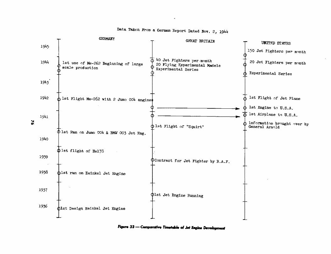
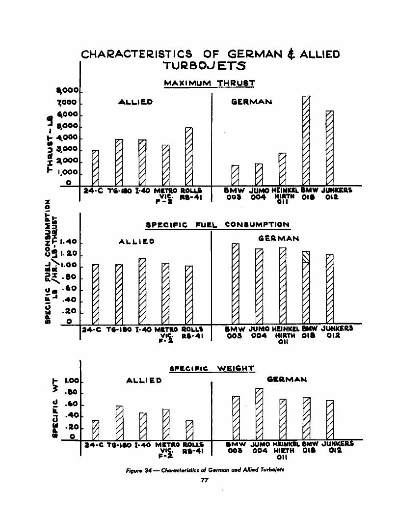

specific weight, 86% the specific fuel consumption, and 75% the diameter of its German counterpart.
SECOND 4-YEAR PROGRAM
This period had the objectives:
(1) Improved turbojets, designated TL, of higher power capable of operation at higher altitudes.
(2) Gas-turbine ducted-fan units, designated ZTL. The English designation "turbofan" is suggested for this unit.
(3) Gas-turbine propeller combination. This is designated PTL. The English term "turboprop" is suggested.
(4) Ramjet.
(5) Research and design studies on gas turbine with heat exchanger for long distance Bight. This has the German designation GTW.
(6) Research and development of the ML. This system is known in this country as the Campini system and is fundamentally a reciprocating engine driving a ducted fan. The engine is in a duct. so that both the engine heat and the exhaust are utilized for jet effect. In addition there are provisisons for burning fuel in the tail pipe for increased thrust.
(7) Research and development on the explosion-type gas turbine. One of the ideas on this subject was the use of the intermittent ramjet. such as the V-I motor, as a source of gas to operate a turbine.
THIRD 4-YEAR PERIOD This period visualized the development to a working state of the following items:
(a) Gas turbine with heat exchanger or GTW system; (b) the Campini type or ML; and (c) the intermittent or explosion turbine.
The second 4-year period was about half over when the war ended. Results of this period are shown in the BMW-018, an improved turbojet of higher thrust rating. 7700 lb, which had a higher compression ratio, 6.6:1, and turbine inlet temperature; and the BMW-028, an experimental turboprop unit of 12,000 equivalent horsepower at 550 mph at sea level. Tabular characteristics of the more important German jet engines are shown in Table I. General information on German units is given in Appendices I and II.
In general, it is seen that the German jet-propulsion program was aimed at a quick victory. The turbojet units in their first 4-year program were frozen too quickly with the idea of a short war. The longer range program had chief emphasis on long-range transport which they had visualized as one of their chief postwar problems.
The German freezing of their first turboj et units and the prolongation of the war enabled our greater facilities for mass production, superior materials and manufacturing technique to overtake their development in turbojets.
In laying out our own plans for future research the important thing is to review German research and thinking toward future development and trends. to compare with our own, and to reevaluate our own program. Table II presents a summary of some of the principal German projects in turbojets and general gas-turbine research, and Table III for turboprops and turbofans.
18

Engine
BMW-003
TABLE I
CHARACTERISTICS OF PRINCIPAL GERMAN JET ENGINES
Thrust (Ib)
1760
Specific Fuel Consumption (Ib/ Ill-thrust)
1.35-1.4
Weight (Ib)
1360
Size
140.4 in. length 27 in. diam.
Turbojet: 7 axiaillow stages, annular combustion chamber, single-stage turbine. In production.
Jumo-004B. 1980 1775 152 in. length 34 in. diam.
Turbojet: 8 axial Ilow stages, 6 straight through combustion chambers, single-stage turbine. In production.
HeinkelHirth 011
2960 1.31 2090 136 in. length 42.5 in. height 34.0 in. diam.
Turbojet: Single centrifugal compressor plus 3 axial flow stages, annular combustion chamber, 2-stage turbine. Prouction starting.
Jumo-012 6400 1.2 4400 205.2 in. length 45 in. diam.
Turbojet: 11 stages axial flow compressor, 2-stage turbine. 10 engines on order; parts for 3 were being made.
BMW-018 7500 1.08-1.3 6400 194.4 in. length 48.72 in. diam.
Turbojet: Compressor, 12 axial flow stages, annular combustion chamber, 3 turbine stages. In design stage.
Jumo-022 This was to be the 012 with contrarotating propellers but had not gone beyond the project stage.
DB-021 1100 hp jet at 500 mph 3300 bhp
0.81Ib/hp/hr 2870 182.4 in. length 33.6 in. diam.
Gas turbine for propeller drive, 9-stage axial flow compressor. ------------------------------~---
BMW-028 7700 bhp .58-.68Ib/hp/hr 7541 234 in. Equiv. hp at length
500 mph - 48.72 in. 12,000-14,000 hp diam.
Gas turbine for propeller drive. modi6ed from BMW-018 to drive a contrarotating propeller. Still in design stage.
19
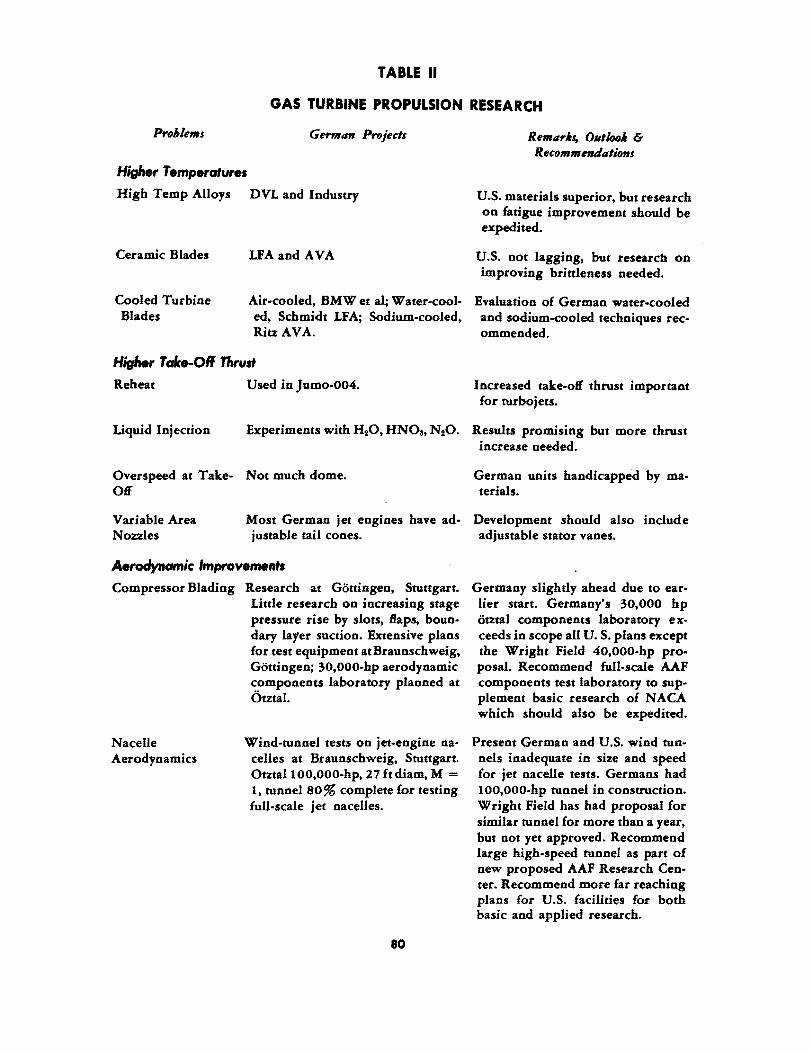
TABLE II
GAS TURBINE PROPULSION RESEARCH
Problems German Projects
Higher Temperature. High Temp Alloys DVL and Industry
Ceramic Blades LFA and A VA
Remar.s, 0.,100. & Recommendations
U.S. materials superior, but research on fatigue improvement should be expedited.
U.S. not lagging, but researcb on improving brittleness needed.
Cooled Turbine Blades
Air-cooled, BMWet al; Water·cool· Evaluation of German water.cooled ed, Schmidt LFA; Sodium-cooled, and sodium-cooled techniques rec. Ritz A VA. ommended.
Higher T alee-Oil Thrust
Reheat Used in Jumo.004. Increased take-off thrust important for turbojets.
Liquid Injection Experiments with H20, HNOa, N20. Results promising but more thrust increase needed.
Overspeed at Take- Not much dome. Off
German units handicapped by materials.
Variable Area Nozzles
Most German jet engines have ad· Development should also include justable tail cones. adjustable stator vanes.
Aerodynamic Improvements Compressor Blading Research at Gottingen, Stuttgart.
titde research on increasing stage pressure rise by slots, flaps, boun· dary layer suction. Extensive plans for test equipment at Braunschweig, Gottingen; 30,ooo.hp aerodynamic components laboratory planned at Otztal.
Nacelle Wind-tunnel tests on jet-engine na-Aerodynamics celles at Braunschweig, Stuttgart.
Otztal 100,OOO·hp, 27ft diam, M = I, tunnel 80 % complete for testing full-scale jet nacelles.
80
Germany slighdy ahead due to earlier start. Germany's 30,000 hp otztal components laboratory e xceeds in scope all U. S. plans except the Wright Field 40,OOO-hp proposal. Recommend fuIl-scale AAF components test laboratory to supplement basic research of NACA which should also be expedited.
Present German and U.S. wind tunnels inadequate in size and speed for jet nacelle tests. Germans had 100,OOO-hp tunnel in construction. Wright Field has had proposal for similar tunnel for more than a year, but not yet approved. Recommend large high-speed tunnel as part of new proposed AAF Research Center. Recommend more far reaching plans for U.S. facilities for both basic and applied research.

Altitude Operation Combustion
Cycle Improvement
Intercooling
Reheat
Regeneration
Closed Cycle
TABLE II (Continued)
Applied work on combustion at companies. One good altitude chamber at BMW, others planned.
Design studies by industry.
Design studies by industry.
More systematic combustion research needed. Also need for AAF altitude wind tunnel for applied development which would allow AERL altitude tunnel to carryon much needed basic altitude research.
German emphasis on mass production of turbojets. Postponed applied work on cycle improvement. U.S. work should be encouraged.
Design studies by industry, A V A Recommend systematic research on ceramic heat exchanger. efficient, lightweight heat exchang
ers.
No evidence of serious consideration. Recommend Ackeret-Keller system at Escher Wyss. Zurich be evaluated in terms of aircraft application, especially with use of helium.
Application to Missiles Subsonic Missiles
Supersonic Missiles
Design studies of expendable turbojets to replace Argus tube of V·l.
No indication of German thought of supersonic turbojet application.
81
Recommend development of expendable, simply constructed turbojet for missile application.
Recommend further studies of supersonic turbojet, and construction of experimental model. Supersonic test facilities for testing propulsion units at supersonic speeds urgently needed.

Items
Turboprop
High-Speed Props
Turbofan
Free-Piston Gas Generator
TABLE III
TURBOPROP AND TURBOFAN
German Projects
BMW-028, adaption of BMW-018, 12,000 hp, 500 mph sea level. Weight 77 00 lb. V nder construction.
Jumo-022, adaptation of 012, 8000 hp at sea level. Preliminary design only.
Daimler-Benz 021, adaptation of Heinkel-Hirth OIl, 4000 hp at 500 mph at 2 5,000 ft. Design stage only.
Tests of swept-back propeller blades at DVL, Berlin. and A VA, Gouingen, show improved efficiency at high flight speeds.
Remarks
V.S. leads Germany in having lowpower turboprop in operations. namely, TG·I00. Germany leads V.S. in development of high-pow. ered unit. namely. BMW-018. Recommend V.S. push development of larger powered units. V. S. needs greater capacity in compressor and turbine test facilities. and wind tunnels for large gas turbine nacelles.
Intensive investigation of sweptback propellers recommended for V.S. since it shows possibility of increasing top speed of propellerdriven aircraft.
Design studies by Junkers. Heinkel, Recommend immediate evaluation BMW. of this drive for V.S. aircraft appli
cation.
Junkers reciprocating free piston and LF A rotating free piston.
82
Rotating free piston shows promise of decreased weight and size over reciprocating a free piston. Recommend German development be evaluated whether advantageous for V. S. application.
OBJECT
RESEARCH ON GAS TURBINE PROPULSION
AT THE LFA
The object of this report is to present a brief summary of various research projects being conducted at the Herman Goring Luftfahrtforschungsanstalt, Braunschweig on gas-turbine propulsion and associated subjects.
FACTUAL DATA
The work on gas-turbine propulsion at the LFA, Braunschweig was surveyed by the Karman Mission, AAF Scientific Advisory Group during the period from 10 May to 1 June 194'.
The work on gas-turbine propulsion at the LFA was divided between two different institutes, one for power plants under Professor E. Schmidt and the other for special power plants under Professor Lutz.
The principal projects of the Power Plant Laboratory under Professor Schmidt were as follows:
As a part of a program toward developing a gas turbine with high operating temperatures, considerable work has been done on the water cooling of turbine blades. A number of radial blind holes were drilled in the turbine blades, with a water feed in one end of the hollow shaft and steam exhaust out the other. The largest holes were about' mm in diameter. The chief principle of operation is the fact that as water is heated it becomes less dense. If water is inserted into a hole running the length of rotating blade, the outer film of water adjacent to the metal becomes warmed and low in density. Since the centrifugal force is proportional to the density, the inner core of water flows outward toward the blade tip while the warm outer layer of water flows inward, thus setting up a natural circulation. According to Professor Schmidt, the pressure due to centrifugal force at the entrance to the holes was about 110 lb/sq in. and at the outer end of the holes about '00 lb/sq in. This pressure is near the critical point, so that heat transfer conditions are greatly improved due to the high value of specific heat.
The water flow is controlled automatically by the depth of water in the rotor. The steam issuing from the other end of the hollow shaft was sufficient to drive a steam turbine of about one-tenth the power of the gas turbine. There is no evaporation in the blade itself, the water evaporating only when it reaches the low pressure in the drive rotor.
In the first complete wheel the holes were drilled from the outside, then plugged. A device was supposedly designed to drill blind holes from the inside.
83

The first unit on which cooling was tried was a 4-stage turbine unit with only one set of rotor blades installed. Stator blades, rotor blades and casing were all water cooled. The stator blades are more difficult to cool due to absence of centrifugal force which provides the natural circulation in the rotors.
This turbine unit, designated T 2, had a tip diameter of 12.6 in. and operated at 12,000 rpm at a temperature of 1200°C. The tip speed was 660 ftl sec. The tempreature of the main body of the blades was 400°C and the trailing edge was 500°C.
A four-stage unit complete with all rotors, designated T a, has been built but has not yet operated. The blades were cut integral with the ribbed drum so that it could run at 20,000 rpm.
A turbine, designated T 4, had been designed for a gas-turbine power plant for MAN, Augsburg, but had not been fabricated. The complete gas turbine was designed for a net output of 5000 kw, and had two axial compressor units in series, with an intercooler between the two. The gas turbine was to be provided with a heat exchanger in the turbine exhaust. The steam from the blade-cooling system was to have been utilized in a high-pressure gas generator supplying fuel for the complete power plant.
Aerodynamic investigations of turbine nozzle shapes have been conducted on a low-speed, cold-air testing rig, for a 9-in. rotor, and on stationary blade lattices in a cascade tunnel. In the cascade tunnel, total head loss and air deflection are measured, in addition to air How studies using the interference method.
The principal projects of the special power plants under Professor Lutz were as follows:
(a) Thermodynamic calculations for gas-turbine propulsion under Dr. Reichert. Recent work has been concerned with the development of a new diagram to aid in studying the problem of increasing the thrust of a turbojet by water injection. A temperature-entropy diagram for saturated air is being prepared, and could be finished shortly.
(b) Interference method for studying jet flow. A special interferometer has been constructed by Steegemaier, and is especially suited for studying duct flow, pulsating as well as steady. The existing apparatus has a 200 x 300-mm field. It was apparently developed with the intermittent jet in mind.
(c) Performance boost by chemical injection. Work on chemical injection to increase the take-off thrust of turbojet engines has been carried on at the firm of Bussing. NAG, in Braunschweig.
(d) Professor Lutz has developed a doughnut-shaped gas generator, utilizing rotating free pistons. Two experimental engines have been built at Bussing. NAG, and were under preliminary tests there. The chief claims for the generator are low specific fuel consumption and a compact combination of compressor and combustion chamber. A more complete description of this development appears in a separate report which follows.
84
THE LFA FREE PilTON ENGINE
This memorandum refers to a new type of free-piston gas generator developed by Professor Otto Lutz of the LF A at Braunschweig, Volkenrode.
The principle of the free-piston engine in general has been known for many years. The main feature is the utilization of floating pistons which, instead of driving connecting rods and crankshafts as in conventional engines, generate compressed and heated gases by recoiling to and fro between cushions of charged air, with combustion taking place at the time of maximum compression of each charge. The products of combustion are then available either to pass directly through a discharge nozzle, furnishing jet propulsion, or they may pass through a turbine, and generate power for driving a propeller or ducted fan.
One of the chief advantages of the free-piston engine is low specific fuel consumption, which is associated with the fact that combustion takes place at a high value of instantaneous pressure, due to the recoil action. In addition, the characteristics at partial load are favorable. For these reasons aircraft engine manufacturers have been interested in the general subject of free-piston engines.
Free-piston engines hitherto known have been too bulky and heavy to warrant seri,?us consideration for aircraft. The new engine is claimed by Professor Lutz to be essentially lighter in weight and smaller in bulk than previous developments, such as the Pescara and Junkers types. This is accomplished chiefly by having a series of pistons rotate and oscillate within a torus-shaped housing, as shown in Fig. 35. The torus has a small frontal area, and is a structurally favorable pressure vessel, so that it can be made light in weight.
Two experimental engines of the so-called "doughnut" type have been fabricated by the firm Bussing-NAG, Braunschweig. This particular design has two banks of three pistons each, which rotate about a central axis. Although both groups of pistons rotate at the same mean speed, they have a superimposed oscillatory motion of such nature that one piston group is always oppositely phased to the other. In this way there are six working spaces, of which three are expanding while the other three are contracting at the same rate. Valves are simple slots which require no further mechanism.
The completed units have a power rating of 400 hp at a mean rotational speed of 800 rpm. The compression ratio at the point of combustion is about 14;1, and the pressure ratio at discharge is 4-6;1. The temperature at discharge is about 1100oF, which means that uncooled turbine blades mp.y be utilized. The piston diameter is 6.6 in. and the housing diameter is 20.5 in. The specific fuel consumption is about 0.33 lb/bhp/hr.
The two engines at Bussing-NAG have had only a short period of preliminary operation, and are in a highly experimental stage. There are no test data available to indicate whether the development is as promising as the designer claims. Systematic investigations of at least one of the existing engines is therefore recommended.
85
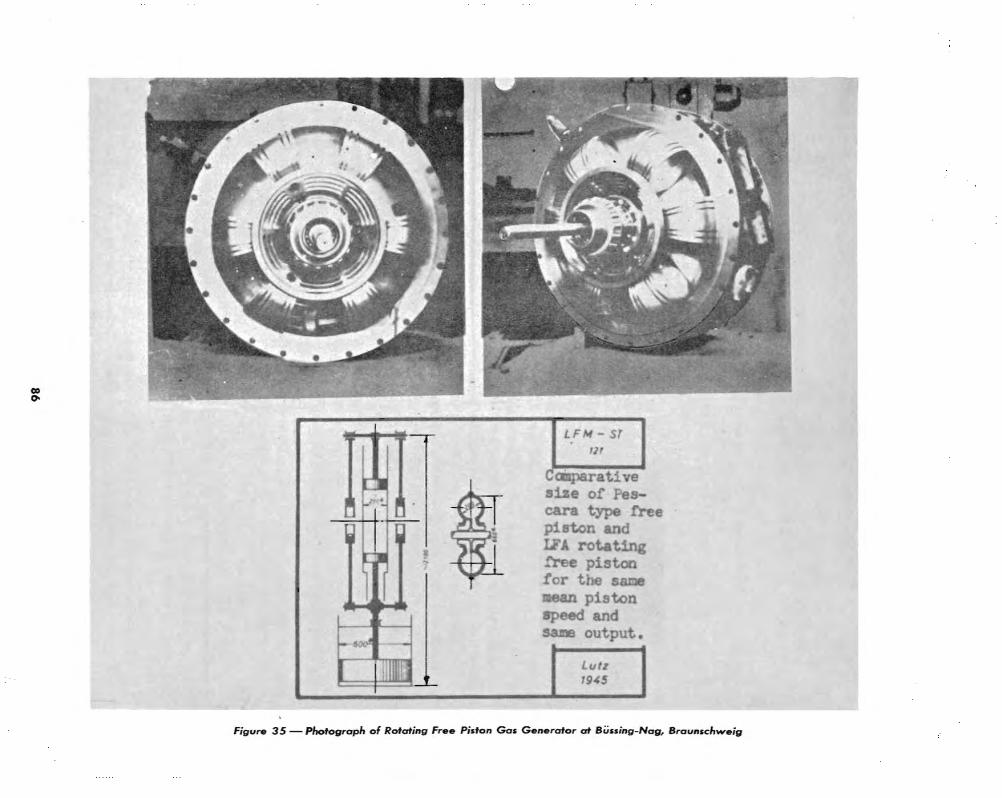

TEST FACILITIES AT THE AVA GOTTIMGEM
The following is a list of aeronautical test facilities at the Aerodynamische Versuchsanstalt, Gottingen. This establishment was investigated by Dr. von Karman, Col. Glantzberg, Drs. Dryden, Tsien, Wattendorf, Schairer, and Col. Dane ofUSSTAF. Dr. Betz, Director of A VA, accompanied the group and supplied this information. The following list covers only the principal items of aeronautical interest and does not include the many small wind tunnels or laboratory installation for calibrating instruments or special investigations.
GENERAL PURPOSE WIND TUNNELS
Tunnel No. Throat Size Maximum Power Remarks Velocity
I circular 7.4 ft 164 ft/sec 3-component and diam (2.25 m) 50 m/sec 300 kw 6-component balance
II elliptical 35 kw 3-com ponent balance 4.9 x 3.3
.1.5 x 1 m
III elliptical m/sec 90kw 3-component balance 1.4 x 1 m
IV circular m/sec 165 kw 2-prop. dynamometers and Propeller 1.25 m balance tunnel
VI elliptical balance Pressure tun- 5.4 x 4 m nel 1/4 atm 7 x 4.7 m 4 atm
Low-turbu- rectangular 90 m/sec 1000 kw located in Ryershausen lence tunnel 1.5 x 3 m
Small icing I rectangular 70 m/sec 80 kw i Lowest temperature 245°K, tunnel • 0.5 x 1 m I refrigeration 80,000
, kcallhr
Large circular 70 m/sec 1600 ~L~we~t tem:perature 220oK, ed and refrig- 4 m diam (norm) Refrigeration 2,000,000 erated tunnel 130m/sec kcal/hr, lowest pressure
(evac) 0.1 atm. Construction not completed
87

HIGH SPEED WIND TUNNELS
There are four high-speed wind tunnels operated by the A V A. Two are supersonic and are operated intermittently, by discharge into evacuated vessels. One of them is now in use, and has a test section which is 110 x 130 mm. The highest Mach number is about 3.2. Lift, drag, and moment can be measured, but due to the short operating time, about 15 sec, only one component is measured at a time.
The other supersonic tunnel has a square test section 250 x 250 mm, and is designed fora Mach number of about 3.5. It is not yet in operation.
The other'two tunnels reach M = 1. One is 215 mm in diameter, and is operated by discharge into a vacuum tank. The other is located in Revershausen, and is driven by steam ejection.
WATER TUNNELS
There are four water tunnels in the A VA, consisting of a vertical spin tunnel with a throat 2.5 m in diameter, and a speed of 3 m/sec; a horizontal tunnel with a rectangular throat 0.7 x 1.0 m, and a speed of 5 m/ sec; and two small tunnels, each 0.25 x 0.33 m and a speed of 5 m/ sec.
FAN AND COMPRESSOR TEST STANDS A low-speed fan test rig accommodates model fans 300 mm in diameter and is
driven by a 3-kw motor at 3000 rpm.
Compressor test stand No.1 has an altitude circuit for rotors between 150 and 200 mm in diameter, and rotates at 30,000 rpm with a compressed-air turbine drive furnishing 70 kw-hr.
Compressor test stand No.2 handles rotors between 150 and 300 mm. Two 100-kw motors can drive two rotors in counter rotation, or may be coupled together to drive one motor. The rotational speed is 30,000 rpm. The test circuit is both evacuated and refrigerated.
A newly erected compressor test stand can accommodate compressor units up to 1000 mm in diameter, and 2.5 mm long at speeds up to 11,500 rpm. The power is supplied by a 2900-kw DC motor.
88
AXIAL COMPRESSOR DEVELOPMENT AT THE AVA,
GOTTINGEN
This report on German axial compressor development and its relationship to turbojet engines is based on interrogations of Dr. Albert Betz, Director of the Aerodynamische Versuchsanstalt, Gottingen, Dip!. Ing. W. Encke, Chief of the Institute of Flow Research of the A VA, and on a review of reports and documents in the A VA.
Research on axial flow fans has been going on continuously since the early 1920's. In 1927 a high-speed test stand was built. This led in 1930 to the development of a five-stage axial supercharger rotating at 30,000 rpm to operate up to 16,500 ft. Although the axial supercharger was never used in aircraft, it gave rise to systematic compressor research with the chief emphasis on obtaining higher pressure ratios with smaller over-all dimensions.
Two test stands were used for most of this development work. One is a low.speed axial fan test stand, Fig. 36, for rotors of 300 mm (11.8 in.) in diameter rotating at about 3000 rpm. The o!,her, shown in Fig. 37, is a small altitude circuit to accommodate rotors between 150 and 200 mm (5.9 to 7.9 in.) in diameter, at rotational speeds up to about 30,000 rpm. The drive i .. !urnished by a compressed air turbine delivering about 70 kw.
Test results on a series of rotors, which represent systematic steps in pitch, are given in a report by Encke entitled "Untersuchungen an Modellradern von Axialgeblasen," U & M No. 3135.
The axial compressor rotor development later became of interest to aircraft companies developing gas-turbine engines for aircraft jet propulsion. Heinkel had started design studies of a jet engine in 1935. Studies of an axial turbojet were initiated by Dr. H. Wagner for Junkers, Magdeburg in 1936. Wagner left Junkers about two years later, and the work was continued under Dr. Franz. In 1938 the AVA developed an 8-stage axial compressor which was adopted by Junkers for the Jumo-004 turbojet engine. This compressor had a pressure ratio of 3.5:1 and a quantity flow of about 40 lb/sec. The tip speed of the totor was 820·890 ft/sec. The efficiency on the test stand was 86%, but as built by Junkers the efficiency ranged between 80 a"ld 84%, depend. ing on the quality of the workmanship.
The Junkers compressor has a stage pressure ratio of about 1.16: 1. Later compressor rotors have obtained higher stage pressures. The highest value to date is 1.3:1, under conditions where the average axial velocity of flow was about one-half of the rotor tip speed. The hub ratio was 0.5 in this wheel as well as most of the series to date. It should be noted that this is an essentially lower hub ratio than is customary for axial compressors. However, Encke investigated one series of rotors at different hub ratios between 0 . .5 and 0.8. Little influence of hub ratio was shown, except that the efficiency had started to drop sharply at 0.8.
89
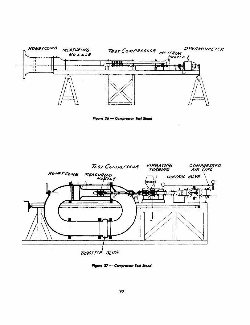
For the rotor which had a stage pressure rise of 1.3:1, the efficiency was somewhat less than 80%. This was a~tributed to a relatively thick blade section and further tests with thinner sections had been planned. The length of the stage, including inlet and exit stator vanes, was about 0.8 times the tip diameter.
Some recent investigations of compressor rotors have been concerned with Reynolds number and Mach number effects. For one rotor type at a tip relative Mach Number of 0.8-0.9, the Reynolds number was changed by changing the product of the number of blades times blade chord. Reynolds number values of 6.10\ 4.105
and 3.10 5 showed little influence on the choking limit. The flow coefficient at the stall point, however, changed from 0.35 to 0.39 to 0.41 in the order of decreasing Reynolds number. At the sa.me time the pressure coefficient decreased from 0.58 to 0.57 to 0.52, while the efficiency showed a total decrease of only 2%.
Some results of tests on the influence of Mach number are shown in the following table, where W "" air velocity relative to the blade, U tangential velocity of the rotor blade tip, V = mean component of axial velocity, C = local velocity of sound.
W Tip Relative Mach number, C 0.74 0.86 1.01
Choking Limit At V U
Maximum Efficiency
Maximum Pressure Coefficient
0.61
0.92
0.59
0.5S
0.88
0.57
0.49
0.82
0.56
Some tests have been made concerning the influence of entrance conditions on the characteristic curve of a compressor. To cite an example, a typical model rotor with a uniform approach velocity had a maximum pressure coefficient of 0.525, at a flow coefficient of 0.32, a maximum efficiency of 0.9. and a choking limit of 0.5S. This same rotor was then subjected to an approach velocity distribution which had the maximum value at two-thirds the radius, 0.6 of this value at the tip and 0.9 at the hub. Under these conditions the maximum pressure coefficient was 0.5 at a flow coefficient of 0.32, the maximum efficiency was about 0.8, and the choking limit about 0.4 5.
It would be important to determine whether in a multistage compressor this effect was limited chiefly to the first stage, or whether it affected all stages in the same degree.
For such relatively small hub ratios, it is apparent that three-dimensional flow should enter the picture to l!- greater degree. In order to investigate this effect in principle, a project on boundary layer measurements on a rotating fan of small hub ratio has been carried out as a doctor's thesis by Himmelskamp, who investigated a twobladed fan 5.00 mm (!S.2 in.) diameter. A cylindrical total head tube projected into the boundary layer of the blade, and its distance an~ angle could be set from the outside.
91

FLOW MEASUREMENT TECHNIQUE
The average level of German development in wind tunnel instrumentation appeared somewhat below our own, although in some instances they had surpassed us, especially in fields such as supersonic aerodynamics where their basic facilities were more advanced. On the other hand, their electronic equipment was generally inferior to ours.
In high-speed. air flow, in both the transonic and supersonic range, instruments which project into the air stream cause excessive disturbance of the flow. For this reason, both German and Allied aerodynamic instrument development work was concentrated largely on methods of studying air flow by methods which do not disturb the flow pattern.
Several interesting German developments were:
(1) Combination Schlieren and interference methods which show both density gradients and lines of constant density on the same observation screen or photographic plate, as shown in Fig. 38.
(2) A novel X-ray method of measuring density, which makes use of the fact that the ionization associated with an X-ray beam is dependent on the density of the medium through which it passes.
(3) A corona method of measuring velocity which utilizes the fact that the potential of a corona discharge varies with the speed of the air passing by.
(4) A spark method of determining local temperature by measuring the local speed of sound at which the disturbance caused by a spark discharge travels.
A brief comparison of German and Allied developments in measurement technique is given in tabular form in Table IV.
92

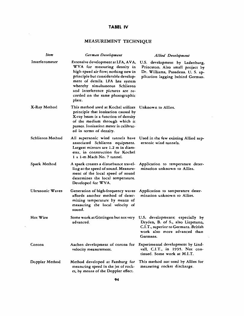
Item
Interferometer
X-Ray Method
Schlieren Method
Spark Method
Ultrasonic Waves
Hot Wire
Corona
Doppler Method
lABEL IV
MEASUREMENT TECHNIQUE
German Development
Extensive development at LFA, A VA, WV A for measuring density in high-speed air flow; nothing new in principle but cnnsiderable development of details. LF A has system whereby simultaneous Schlieren and interference pictures are recorded on the same photographic plate.
This method used at Kochel utilizes principle that ionization caused by X-ray beam is a function of density of the medium through which it passes. Ionization meter is calibrated in terms of density.
All supersonic wind tunnels have associated Schlieren equipment. Largest mirrors are 1.2 m in diameter, in construction for Kochel 1 J( 1-m Mach No.7 tunnel.
A spark creates a disturbance travelling at the speed of sound. Measurement of the local speed of sound determines the local temperature. Developed for WV A.
Allied Development
U.S. development by Ladenburg, Princeton. Also small project by Dr. Williams, Pasadena. U. S. application lagging behind German.
Unknown to Allies.
Used in the few existing Allied supersonic wind tunnels.
Application to temperature determination unknown to Allies.
Generation of high-frequency waves Application to temperature deteraffords another method of deter- mination unknown to Allies. mining temperature I::y means of measuring the local velocity of sound.
Some work at Gottingen but not very advanced.
U.S. developments; especially by Dryden, B. of S., also Liepmann, C.I.T., superior to Germans. British work also more advanced than Germans.
Aachen· development of corona for Experimental development by Lind-velocity measurement. vall, C.I.T., in 1935. Not con
tinued. Some work at M.LT.
Method developed at Fassburg for measuring speed in the jet of rock· et, by means of the Doppler effect.
94
This method not used by Allies for me~sucing rocket discharge.

Item
Electromagnetic
Piezo Electric Capsules
Electromagnetic Pressure Capsules
Half Models
Cavitation
Simulated TurboJets
Flexible Walls
Half·Open Jets
TABLE IV (Continued)
German Development
Used in many of the intermittent wind tunnels, such as LF A, A V A, WV A, to measure transient forces.
Allied Development
In common use in U.S. wind tunnels. Electronic technique in general superior to German.
Used at LFA for measuring transient This method is also in use by Allies forces. for special purposes.
Used at LFA and WVA for measur- U.S. developments, i.e., for Wright ing transient pressures. WV A has Field wind tunnels, considered small capsules with linear charac- superior. teristics.
This technique used at WV A; convenient for measuring pressures, hinge moment, etc.
Similarity between cavitation and compressibility phenomena used for qualitative work in water channels on simulated critical compressibility conditions.
For wind-tunnel models, small highspeed compressors are used to simulate internal flow, and alcohol is burned to introduce heat.
In some supersonic tunnels continuous flexible walls for the test section are used to change Mach number. Some tunnels used fixed nozzles and variable diffuser.
In some supersonic tunnels the test section is pardy closed and partly open. This is said to decrease wall interference, especially through transonic range.
95
This technique also used at C.I.T.
Water channels not used by Allies for simulated compressibility effects.
Not as yet used by Allies for wind. tunnel models of jet aircraft.
Flexible walls have been ordered for Aberdeen, Wright Field, and Ames supersonic wind tunnels, Flexible walls have been in use for several years by NACA and in England.
This technique not as yet used by the Allies for supersonic flow.
GERMAN WIND TUNNELS
This report contains a tabular presentation of the principal characteristics of German wind tunnels, including those in German-occupied countries, up to the summer of 1943. Some of the more important wind-tunnel projects completed after the summer of 1943 or still under construction, were inspected by the Karman Mission, AAF Scientific Advisory Group during the period from 1 May to 20 June 1945. A brief description of these tunnels is- also included in this report.
TABULAR SUMMARY OF THE GERMAN WIND TUNNELS
The information on German wind tunnels up to the summer of 1943 is based on Deutsche Luftfahrtforschung U & M Nr 750 "Zusammenstellung der deutschen Windkanale" by Weiss. A tabular summary of the principal characteristics of these wind tunnels is given in Appendix III, together with a brief explanation of the terminology. Supplemental information on more recent wind tunnels, including those under construction, was obtained by a recent survey of the Karman Mission, AAF Scientific Advisory Group, and will now be given.
OTZTAL WIND TUNNEL
The Otztal wind tunnel is located near the confluence of the Inn and Otz Rivers in the Austrian Tyrol about 35 km west of Innsbruck. It has an 8-m diameter throat and was designed to reach the speed of sound at a maximum power input of 100,000 hp. The tunnel is atmospheric with a maximum air exchange of 20%. The power was to be furnished by two Pelton water turbines delivering 50,000 hp each, directly connected to countcrrotating fans. The hydraulic power was to be furnished by a flow of water of 18 cu m/sec with a head of 500 m. The tunnel was intended to make highspeed aerodynamic tests on complete aircraft models, on full-scale component parts of aircraft and on full-scale nacelles with operating propulsion system. The tunnel is about 70% completed and was scheduled for operation in 1945. This tunnel was the first item of a planned research center which included the second 100,000-hp wind tunnel and a 30,000.hp compressor and turbine laboratory. The over-all value of this
, research center would correspond to about $60,000,000 to $75,000,000 in U. S. money. The project was under the jurisdiction of the LFM in Munich
KOCHEL SUPERSONIC TUNNEL
A 76,OOO-hp supersonic wind tunnel was under construction at Kochel in Southern Germany. This tunnel was to have a 1 x l-m throat, and continuous operation at a Mach number 7.0 was planned with possible extension to a Mach number 10. The purpose of this tunnel was the development of long-range winged missiles capable of crossing the ocean. Construction of this tunnel started in November, 1943 and was
96
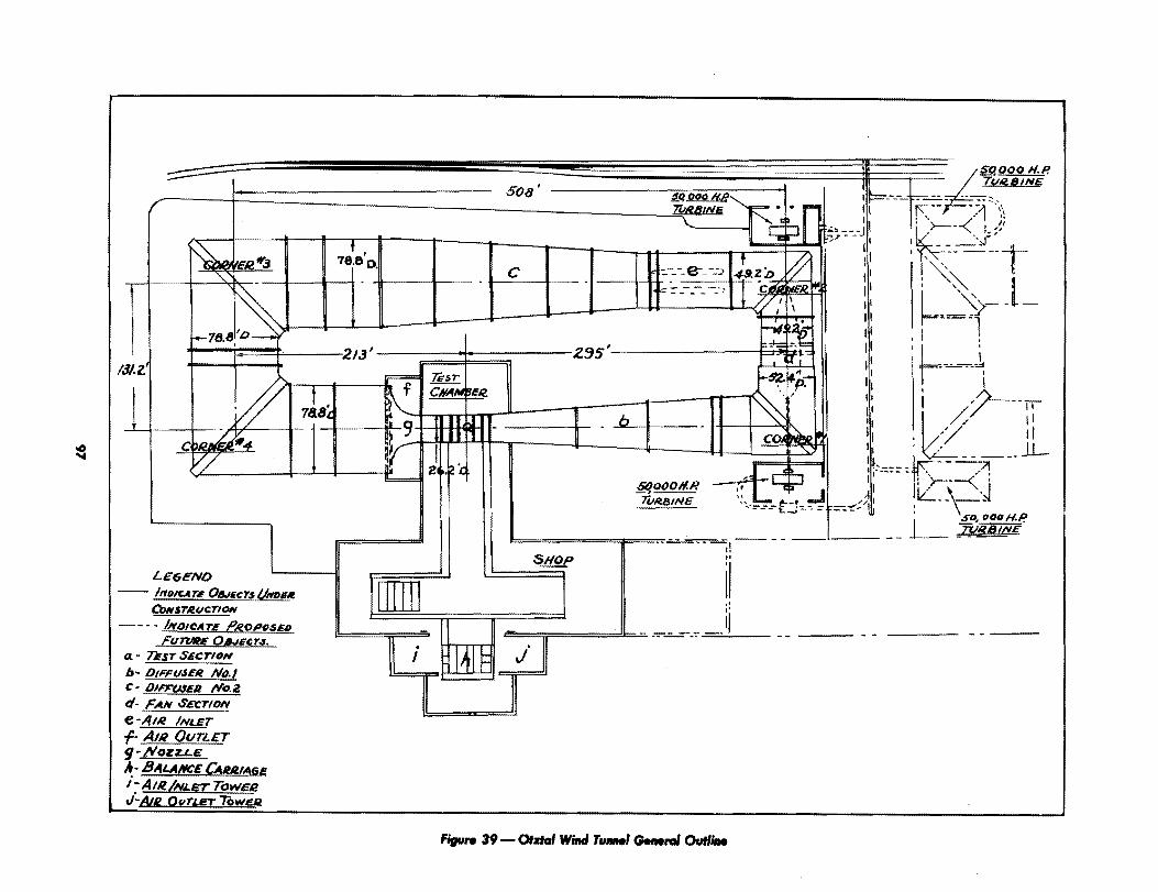
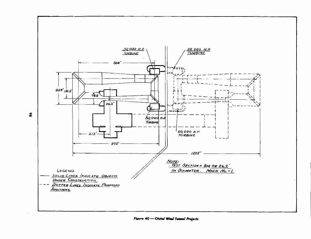
estimated for completion in the fall of 1945. About 25,000,000 marks were set up for the project of which 15,000,000 had been obligated. The power was to have been furnished by seven compressor aggregates, with each of the first four aggregates driven by a 12,000-kw hydraulic turbine and each of the last three aggregates driven by an electric motor, the electric power for which was to be furnished by a 3000.kw hydraulic turbine. The compressor system has an inlet suction quantity of 1,200,000 cu m/hr at a vacuum of 1.4 mm of mercury. The silica-gel drying system was to have a capacity of 780,000 kg of air per hour with an inlet humidity of 12 gm/kg, and a discharge humidity of less than 0.5 gm/kg. The Schlieren apparatus utilized two mirrors 1.2 m in diameter with a focal length of 9.25 m. Throats were to be fixed and interchangeable while the diffuser was to be adjustable.
GOTTINGEN ALTITUDE WIND TUNNEL This tunnel was a double-closed return type with an open jet 4 m in diameter.
It was made of very heavy concrete construction and could be evacuated to 0.1 atm and refrigerated to - 64°F. The refrigeration capacity was 2,000,000 kg-cal/hr. The fan bhp was 2100 hp and the jet air speed was estimated at 70 m/sec at sea level and 130 m/ sec at altitude. A unique feature of this tunnel was the use of a large Flenner rotor at each corner instead of the usual corner vanes. This was to prevent icing difficulties at the corners. The purpose of this tunnel was to conduct altitude tests On nacelles with operating propulsion syste~s especially of the gas-turbine type. In addition the tunnel was to be capable of making icing tests. The tunnel was more than 80% completed and was scheduled for operation during 1945.
LFM 3-M SONIC TUNNEL This tunnel had just been completed at Munich and calibration had been initiated.
The tunnel is of the single-closed return type with a closed throat 3 m i.n diameter and was designed to reach a speed of sound in the throat with a power input of about 10,000 kw. The unique feature of the tunnel is that the entire large end of the tunnel can be disconnected and rolled away on tracks, thereby converting the tunnel into an open return type to be used when testing operating propulsive systems in the throat.
LFM 40 x 40-CM SUPERSONIC WIND TUNNEL This tunnel was to have been a continuous flow type to attain a Mach number 2.8
in the throat of dimensions 40 x 40 cm. The motor power was to be supplied by a Brown Boveri 4500-hp axial compressor, driven by a Ward-Leonard motor generator set. The axial compressor system had just been delivered to the site and had not as yet been un crated. The rest of the tunnel had not been assembled.
LFM 25 x 25-CM SUPERSONIC TUNNEL This tunnel was an intermittent tunnel operated by a suction tank and was de
signed for Mach number 3.2 with a 25 x 25-cm throat. It was under construction at the LFM. '
WVA 40 x 40-CM SUPERSONIC WIND TUNNEL This tunnel was formerly at Peenemunde and had been erected at Kochel., It was
operated by a vacuum tank of 1,000 cu m and was designed to attain a Mach number of . 4.4 with a throat 40 x 40 cm. It was almost ready for operation at the site.
99
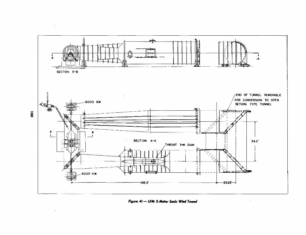
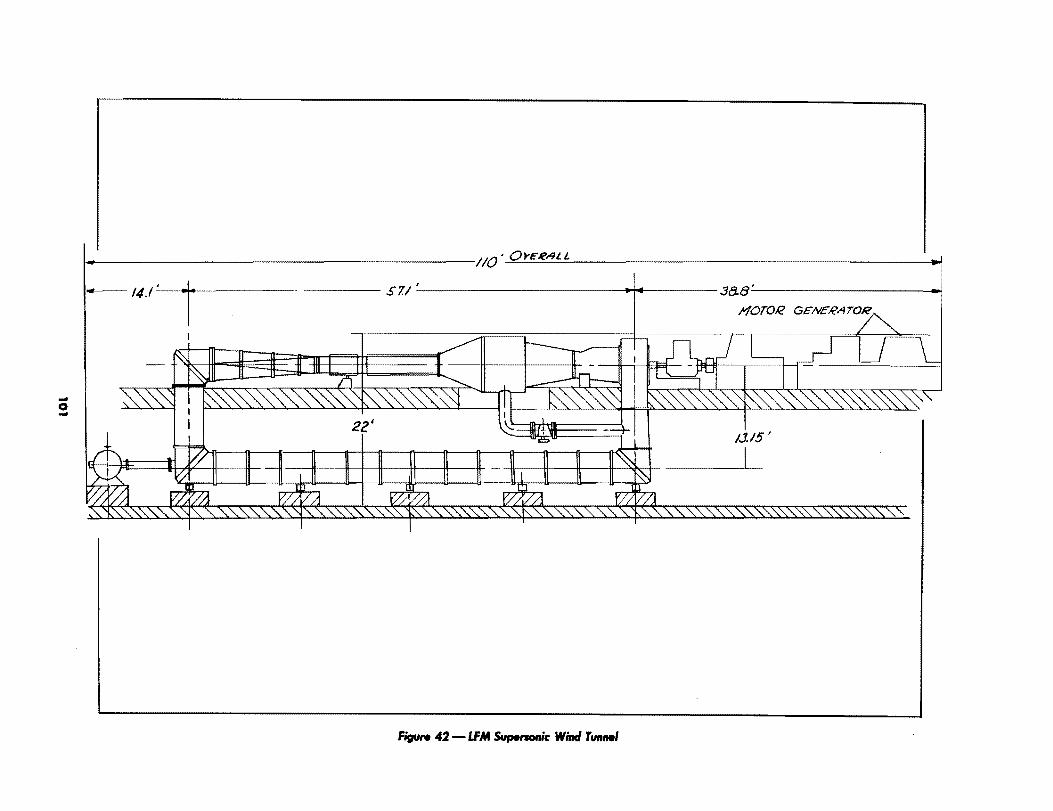
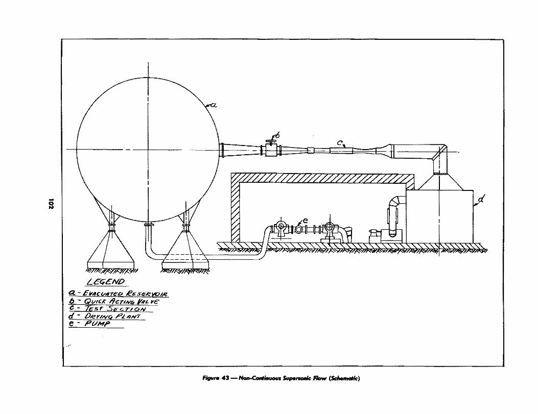

KOCHEL SUPERSONIC WIND TUNNELS
The Aerodynamics Institute formerly at Peenemiinde was moved in the latter part of 1943 to Kochel in Southern Germany and started operation in 1944 as an independent organization under the name of Wasserbauversuchsanstalt Kochelsee. The establishment at Kochel was visited on 15 June by Drs. H. L. Dryden, F. L. Wattendorf and H. S. Tsien, of the Karman Mission, AAF Scientific Advisory Group, and the present notes are based on interviews by this group with Dr. Herrmann and other key personnel of the establishment.
One 40 x 40-cm supersonic tunnel started operation at Kochel in October, 1944. It has attained a Mach number of 4.4. This tunnel is of the intermittent type and exhausts into a cylindrical tank of 750 cu m volume at less than 10% vacuum.
A second supersonic tunnel also 40 x 40-cm cross section is almost ready for operation. This tunnel exhausts into a sphere of 1000 cu m volume.
A third supersonic tunnel with an 18 x 18-cm throat is ready for installation. This tunnel is continuous in operation and connects to the large 1000 cu m sphere, which acts as a settling chamber between the pumps and the tunnel. It was planned to start a test run with the sphere evacuated, then to maintain a working vacuum by continuous operation of the vacuum pumps.
There are three 270-kw aggregates of two vacuum pumps each made by Demag Duisburg. With two pumps in series a 1 % vacuum is attainable. With parallel operation a 10% vacuum is attainable in the cylinder in a time of 3 to 4 min. At a Mach number of 3.2 the 10% evacuated cylinder allows a test of 15 sec duration. The exhaust pipe is 80 cm in diameter.
The nozzles are made of brass and are extremely accurate. A jig in the machine shop allows checking to .0002 cm. It is estimated that 2000 man-hours are required for one nozzle. The nozzles are built as inserts and can be changed in about 15 min by use of the overhead crane.
Two streamlined struts are used for model support, one from below and the other from the top. One strut is a dummy and used to evaluate the tare. A compact balance system, using reluctance-type gages, is located in a false roof immediately above the tunnel throat. The forces are measured through the deflection of stiff springs. Spring deflections of .0001 to .0002 mm can be detected by the gages. It is estimated that forces of from 3 to 5 kg can be measured accurately to 10 gm.
The inlet air is dried by the silica-gel method. It is estimated that the maximum allowable moisture content of the air for satisfactory operation is about 0.5 gm/kg. In the Kochel tunnel. however, an attempt is made to limit the moisture content to a value of 1/10 .gm/kg. The silica-gel is reactivated after each run. For determining moisture content, a special psychrometer of the sulphuric acid type was delivered several months ago by the Technical Institute of Danzig.
103
At a Mach number of 3.2, it is estimated that the adiabatic throat temperature ranges between -60° and 150°C. At the same time, however, the temperature at the model surface might rise as high as 600°C.
Models tested include the Peenemiinde Pfeilgeschoss (PPG) for railway guns, supersonic mines for M = 1.5 to 1.8, the FC-50 bomb, the Wasserfall, the A-4 or V-2, ramjets, semimodels and simulated jets.
A new .."ltrahigh-speed supersonic wind tunnel is under construction. This tunnel has a throat 1 x I m and a 57 ,Ooo-kw hydraulic drive. Continuous operation at a Mach number of 7.0 is planned with possible extension to a Mach number of 10. The purpose of this tunnel was the development of long-range missiles, such as the transatlantic version of the V-2. Construction of this tunnel started in November, 1943 and was estimated for completion in the fall of 1945. About 25,000,000 marks were set up for the project, of which 15,000,000 have been obligated. The tunnel was to have a half-open throat in order to minimize wall interference. Mirrors for the Schlieren apparatus are 1.2 m in diameter and are under contract to Zeiss. The focal length of the mirrors is 9.25 m. The entire Schlieren apparatus is mounted on a framework which is moved on rails along the tunnel axis. Throats are fixed but interchangeable and the diffuser is variable. There are four test sections and three air filters planned.
There are seven compressor aggregates whereby each of the first three have three II-stage axial compressors in parallel and the other four are composed of 4-stage centrifugals. The over-all compression ratio is 1:875. The vaccum system has a suction quantity of 1,200,000 cu m/hr while attaining vacuum of 1.4 mm of mercury. Each of the first four vacuum pump aggregates is driven directly by a 12,000 kw hydraulic turbine; each of the last three stages is driven by an electric motor, the electric power for which is furnished by a 3000 kw hydraulic turbine. The turbines were to be furnished by Voith in Heidenheim and the vacuum pumps by Brown Boveri ofMannheim.
The Silica-gel drying system has a capacity of 780,000 kg/hr of ajr with an inlet humidity of 12 gm/kg and a discharge humidity of less than 0.5 gm/kg. The drying apparatus is being furnished by Firma Silica-gel Gesellschaft, Berlin. The test section and associated parts such as diffuser, three component balances and Schlieren equipment, are being furnished by Firma Dingler, Zweibriicken. The construction of the tunnel was started in November, 1943 with an estimated completion in two years. Geological investigation and surveying has been completed. Fabrication of machine parts for the tunnel was stopped in September, 1944.
Considerable development work has been carried out on interference apparatus of the Mach-Zender type. This equipment was designed by Winkler and fabricated by Zeiss Company of Vienna. In addition a photocell analyzer was developed for the evaluation of interference patterns.
The Schlieren system used at Kochel utilized specially fabricated mirrors developed by Professor Walters at Darmstadt, and the resulting Schlieren photographs were claimed to have improved clarity.
A new method of measuring air density utilizing X rays was a special development by Professor Rau of Darmstadt. In this method a beam emitted by an X-ray tube was passed through the air stream. At the other ~ide of the air stream was located an
104
ionization meter. Since the ionization of an X-ray beam is a function of the density of the medium through which it passes, the reading of the ionization meter can be calibrated in terms of air density.
Small electromagnetic pressure capsules of about 1/2 in. in diameter had been fabricated. These were said to be sensitive to .01 mm of mercury column.
The organization of the Kochel establishment is given in Appendix IV.
OTZTAL WIND TUNNEL
The Otztal wind tunnel has an 8-m diameter throat and is designed to attain M = 1 at a maximum power of 100,000 hp. The tunnel is atmospheric and has a maximum air exchange of 20%. It is driven by hydraulic power with a head of 500 m. The money appropriated for the tunnel is 40,000,000 marks for the power plant and about 30,000,000 marks for the wind tunnel proper. It is abou.t 70% completed and was scheduled for operation in 1945. This tunnel was the first item of a planned research center which included a second 100,000-hp wind tunnel and a 30,000 hp compressor and turbine laboratory. The over-all value of this research center would correspond to about $65,000,000 in U. S. money.
DESCRIPTION
The Otztal wind tunnel project was inspected on 13 June 1945 by Drs. H. L. Dryden, F. L. Wattendorf and H. S. Tsien of the Karman Mission, AAF Scientific Advisory Group. The site of the project is near the confluence of the Inn and Ou Rivers in the Austrian Tyrol about 35 km west of Innsbruck. This location is particularly suited for hydraulic power, furnished by a drop of 500 m from the Stuibenbach River. The water available is maintained the year around by snow and glaciers from the nearby Otztal Alps. The general arrangement of the tunnel site is shown in Fig. 39.
The tunnel is a single-return type with a circular cross section. The throat diameter is 8 m and the maximum diameter 24 m. With a power input of 100,000 hp, the tunnel is designed to reach the speed of sound at the throat with no model in place. The general outline of the tunnel is shown in Fig. 40. It is constructed of rolled and welded steel plate of a thickness between 3/8 and 5/8 in. The tunnel is provided with an air exchange system with the quantity of fresh air adjustable between 0 and 20%. The air exhausts through an annular slot upstream of the nozzle, and the fresh air inlet islocated in the second diffuser downstream of the second corner. The over-all length of the tunnel is 1 74 m.
The power is furnished by the two Pelton turbines delivering 50,000 hp each at 220 rpm, directly connected to two counterrotating fans af 15-m diameter. The first fan has 14 blades, the second fan has 12 blades. The fan blades are constructed of steel sheets wrapped around a center tubular spar and box beam, and welded at the trailing edge.
105

The tunnel was projected to make high-speed aerodynamic tests on full-scale nacelles with power plaus of either the reciprocating or gas-turbine types; on complete aircraft models, or on full-scale component parts of aircraft. In order to facilitate this type of general purpose testing, three interchangeable balance systems were to be provided. Each balance system was to be mounted on a carriage and could be rolled on a track into place in the test section. A convenient feature for the preliminary calibration and testing of propulsive systems is the arrangement whereby the full-scale nacelle can be mounted on one of the balances, and rolled into a horse-shoe type of test cell at the end of the test chamber building opposite the test section. The inlet air would be drawn from the atmosphere through one leg of the horse shoe and discharged upward through the other leg. This means that propulsive systems could be mounted, shakedown runs performed, and static calibrations obtained without interfering with current wind-tunnel tests. When ready, the unit assembly mounted on the balance could be wheeled as a whole into the test section for wind-on test. The balance was to utilize oil pads for resolution of the forces and hydraulic cylinders for measuring the forces. Fabrication of both balances is partially complete at Firma Schenk in Darmstadt.
The hydraulic system was a cooperative project with the Westtiroler Kraftwerke, a power company with plans for a 1,000,000-kw project for supplying the region of the German Rhine with power. The water requirements of the tunnel alone was 18 m 3/sec at a head of 500 m.
The tunnel project was one of a forward-looking and progressive wind-tunnel program for Germany as a whole, as conceived apparently by Dr. Baumker of the Research Council in Berlin. The funds were supplied by the German Air Ministry. The Aeronautical Research Institute of Munich was to be the operating agency. Dr. H. Peters of the LFM was the designer of the tunnei, and Dr. Schwaiger of the Research Council has been in charge of the project in recent months. Dr. Schwaiger was residing at the site and furnished the information in this report. Funds in the amount of about 30,000,000 marks were allocated for the wind tunnel and 40,000,000 marks for the power installation. In American money, this project would probably entail at least $30,000,000. Work is about 70% completed in the contractors' plants and at the site.
The actual work on the tunnel project was subdivided among the following contractors:
(a) Hydraulic power system including dams, tunnels, etc., by the Westtiroler Kraftwerke and the Siemens Bau-Union, SBU, as well as Innerebner & Mayer.
(b) Buildings and foundations, Arbeitsgemeinschaft Innerebner & Mayer, Ph. Holzmann, A. G.
(c) Wind-tunnel fabrication, MAN, Maschinenfabrik Augs burg-Nurn berg, Werke Gustavsburg.
(d) Turbines, Dinglerwerke, Zweibrucken,J. M. Voith-Heidenheim/St. Polten.
(e) Water ducts and piping, Krupp, Dormunder Union.
(f) Test stands and carriages, MAN, Gustavsburg.
(g) Balances, Schenk, Darmstadt.
It is estimated that completion of the tunnel would have required between six months and one year as shown in Fig. 4 L
106

THE 2.8-METER HIGH SPEED WIND TUNNEL OF THE
HERMANN GORING LUFTFAHRTFORSCHUNG
SANSTALT (LFA) BRAUNSCHWEIG
The general arrangement of the LF A high-speed wind tunnel is shown in Fig. 44. It is a closed-return tunnel with a cylindrical test section of 2.8 m diameter. The maximum speed of the tunnel is M = 1 with no model, and approximately .8' with model, although this will depend on the model dimension.
The tunnel circuit is arranged in a vertic~l plane as shown. The air is circulated by a two-stage' fan, located upstream of the first corner. Both fans rotate in the same direction and have a set of contravanes between the fans to counteract the spin.
The tunnel is normally closed but cooling is provided by air exchange, which can be regulated up to a total amount of 20%. The hot air outlet takes place downstream from the first corner, by means of an adjustable bleed flap, the fresh air enters first the wind tunnel building through louvers and then the tunnel circuit downstream from the second corner, through thin hollow struts with adjustable openings as shown in Fig. 4.5.
There is a honeycomb in the large section following the fourth corner. The nozzle has a 7:1 contraction ratio.
The test section is 2.8 m in diameter and 4 m long. The adjoining diffuser is 33m long and the walls are conical with a total included angle of 7°. With a maximum throat speed corresponding to M = I, the axial velocity entering the fan section at the downstream end of the diffuser is about 40 m/sec.
A unique feature of the tunnel is that it may be easily converted to an open return or Eiffel type when testing propulsion devices giving off products of combustion. The discharge is opened by shifting the upper left hand corner to the right, which at the same time seals off the upper leg of the return circuit. In the same way the upper right hand corner is shifted to the left which allows an intake of fresh air vertically downward.
A protective net fabricated of 9.'-mm wire is stretched across the tunnel crosssection about 10ft before the fan. An interesting feature is that the net is supported by 24 cables which pass through the tunnel shell and fasten t9 oil-damped cylinders. In this way the shock of a heavy impact can be absorbed without breaking the net.
The two fans are driven through a common shaft by two direct curre,nt motors of 6000-kw rating each. The motors are located outside the tunnel and the drive shaft has a bearing support before each fan stage. The maximum rotational speed of the fan drive is 600 rpm. '
The main power supply comes in at .50,000 v and is transformed down to 1200-1600v, then passes through a mercury vapor rectifier which furnishes a smoothly con-
107
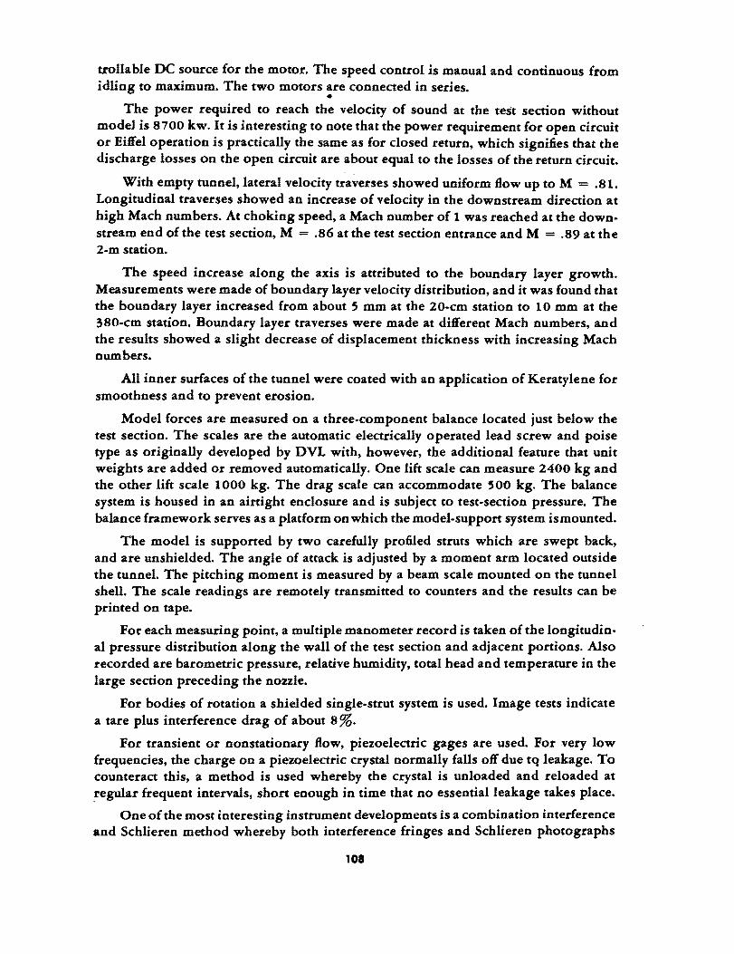
trollable DC source for the motor. The speed control is manual and continuous from idling to maximum. The two motors are connected in series .
• The power required to reach the velocity of sound at the test section without
modeJ is 8700 kw. It is interesting to note that the power requirement for open circuit or Eiffel operation is practically the same as for closed return, which signifies that the discharge losses on the open circuit are about equal to the losses of the return circuit.
With empty tunnel, lateral velocity traverses showed uniform flow up to M = .81. Longitudinal traverses showed an increase of velocity in the downstream direction at high Mach numbers. At choking speed, a Mach number of 1 was reached at the downstream end of the test section, M = .86 at the test section entrance and M = .89 at the 2-m station.
The speed increase along the axis is attributed to the boundary layer growth. Measurements were made of boundary layer velocity distribution, and it was found that the boundary layer increased from about 5 mm at the 20-cm station to 10 mm at the 380-cm station. Boundary layer traverses were made at different Mach numbers, and the results showed a slight decrease of displacement thickness with increasing Mach numbers.
All inner surfaces of the tunnel were coated with an application of Keratylene for smoothness and to prevent erosion.
Model forces are measured on a three-component balance located just below the test section. The scales are the automatic electrically operated lead screw and poise type as originally developed by DVL with, however, the additional feature that unit weights are added or removed automatically. One lift scale can measure 2400 kg and the other lift scale 1000 kg. The drag scale can accommodate 500 kg. The balance system is housed in an airtight enclosure and is subject to test-section pressure. The balance framework serves as a platform on which the model-support system is mounted.
The model is supported by two carefully profiled struts which are swept back, and are unshielded. The angle of attack is adjusted by a moment arm located outside the tunnel. The pitching moment is measured by a beam scale mounted on the tunnel shell. The scale readings are remotely transmitted to counters and the results can be printed on tape.
For each measuring point, a multiple manometer record is taken of the longitudinal pressure distribution along the wall of the test section and adjacent portions. Also recorded are barometric pressure, relative humidity, total head and temperature in the large section preceding the nozzle.
For bodies of rotation a shielded single-strut system is used. Image tests indicate a tare plus interference drag of about 8 %.
For transient or nonstationary flow, piezoelectric gages are used. For very low frequencies, the charge on a piezoelectric crystal normally falls off due tq leakage. To counteract this, a method is used whereby the crystal is unloaded and reloaded at regular frequent intervals, short enough in time that no essential leakage takes place.
One of the most interesting instrument developments is a combination interference and Schlieren method whereby both interference fringes and Schlieren photographs
108
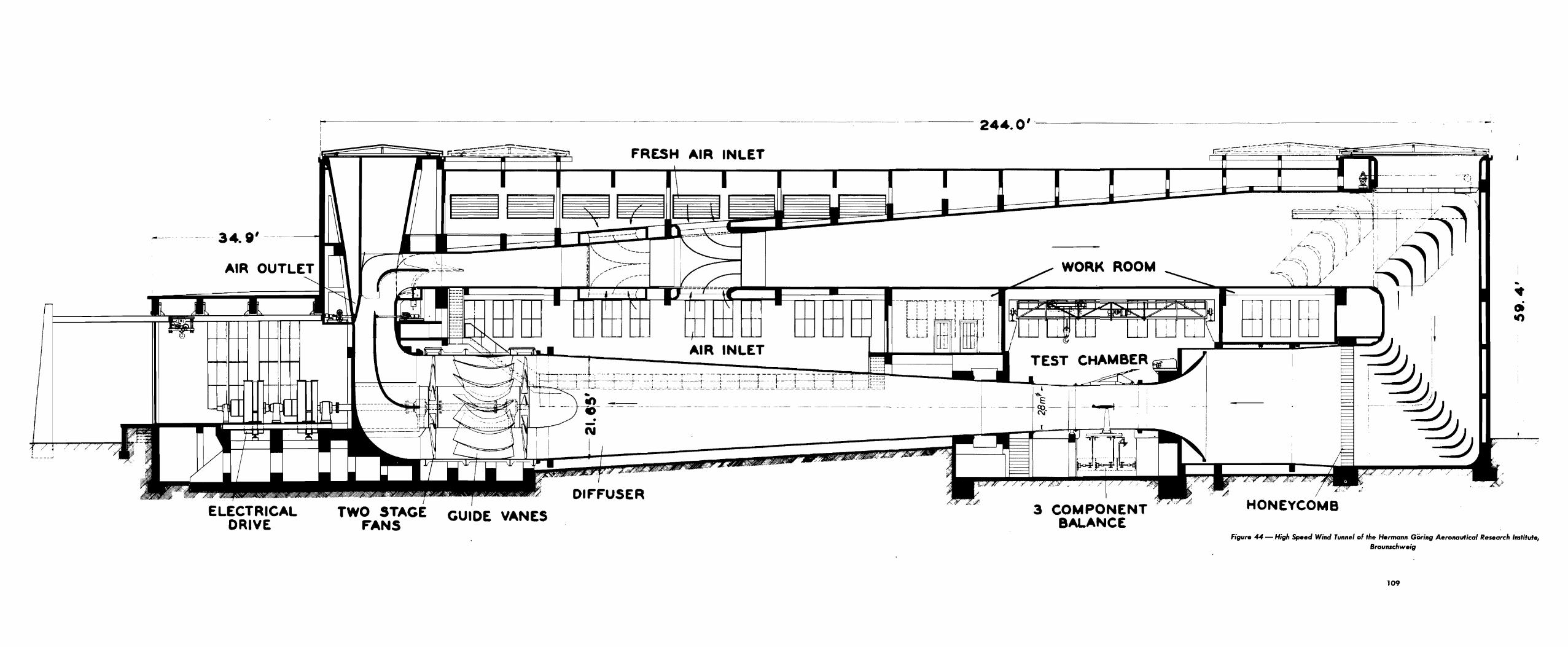

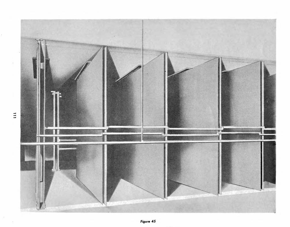
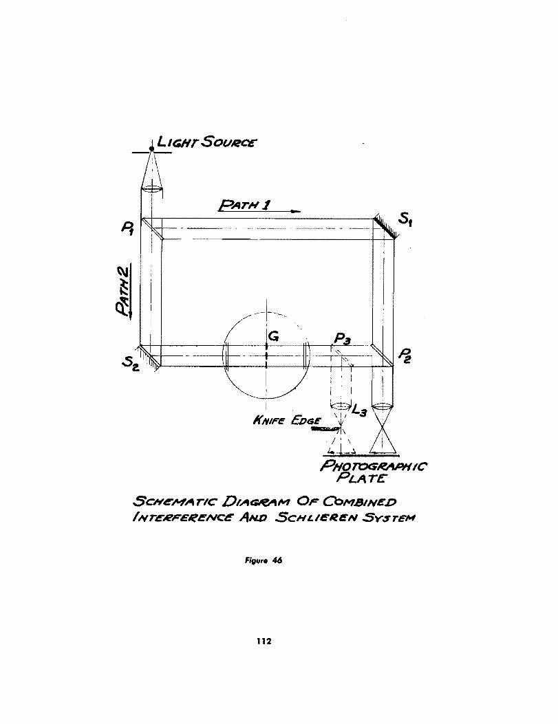

can be taken simultaneously on the same exposure of film. This is accomplished by the use of a system of mirrors as shown in Fig. 46. A mercury lamp is the light source, and the light rays pass through a semitransparent mirror at PI, so that one·half of the rays take path 1 to P 2 and the other half follow path 2 to P 2. Paths 1 and 2 are equal in· distance. Mirrors Sl and S2 are fully reflective, while mirrors P 2 and P a are partially transparent, as Pl. The resultant rays from P2 are collected by a lens, pass through a color filter and show the interference fringe pattern on a screen, or record on a photographic plate or film. The rays from P 3 pass through lens L3 and over a knife edge, and record the Schlieren type of density gradient on the other half of the photographic plate or film.
This.method should be of value in high-speed flow studies since it combines the great sensitivity of the interference fringe method with the more familiar physical picture of the Schlieren density gradient. It is recommended thai this optical system be evaluated in terms of application to high-speed air-flow studies in allied wind tunnels.
REFERENCES
1. Th. Zobel, Der Hochgeschwindigkeitskanal der LFA von 2,8-m Durchmesser und seine Messeinrichtungen. Schr. d. Dt. Akad. d. Luftfahrtforsch H. 1060/43 g.
2. Th. Zobel, Fortschritte in der Optischen Strbmungmessung.
113

CONFERENCE AT BROWN BOYERI, BADEN,
SWITZERLAND
CONFEREES
Scientific Advisory Group members were Drs. Th. von Karman, H. L. Dryden, H. S. Tsien, F. L. Wattendorf, Col. F. E. Glantzberg, and Lt. Col. G. T. McHugh.
Brown Boveri representatives were Drs. A. Meyer, C. Seippl, G. Datwyler, G. Darrieux, and van Ryswyck.
RESULTS OF CONFERENCE
The axial compressor built for BBC for the Zurich T. H. supersonic wind tunnel about 10 years ago has been used as a more or less standard for the past 10 years. About 100 have been built.
The largest axial compressor they are now building has a mass flow of 30,000 kg/hr at a pressure ratio of 4:1. The compressor is about 4 ft in diameter, has a maximum rotational speed of 3000 rpm, and absorbs about 15,000 kw.
Concerning supersonic wind tunnt!ls, they believe that a test section of about 2 x 2 ft is the largest size practicable for one compressor. For larger tunnels, they believe it would be better to have several compressors since one large compressor would be more costly and difficult to build.
They estimate 10-12 months as delivery time for a standard compressor. Forgings are the critical items.
Possible improvements in axial compressor design were discussed. BBC stated that the stage pressure ratio of their standard units was 1: 1, and had not been increased over the past 10 years because there had not been any particular reason for needing higher stage pressures for commercial, stationary gas-turbine plants. They realized, however, that aircraft application did require higher stage performance, and for that reason were now becoming interested in developing basic improvements. First, they were going to make flow tests on stationary grids, then apply the results to an 8-10 stage experimental machine.
They have tried blades with more camber, but get "an earlier decrease of efficiency with increased speed. However, they have not made enough investigations to see whether this premature drop could be eliminated by proper aerodynamic design.
BBC's present standard design method calls for a 50/50 reaction maintained over the whole blade length. This method results in unbalanced centrifugal forces, which, however, BBC does not consider serious since they attain an 82% stage efficiency and 86% over-all adiabatic efficiency. Dr. von Karman believes that balancing of the radial
114
forces might increase the stage efficiency to 92 %. BBC admitted that the problem would become increasingly important with higher stage pressures. Datwyler is making preliminary investigations on radial flow in turbine blades.
Pumping Limit. The question was asked whether the pumping phenomenon was more severe with
axial or centrifugal compressors. Seippl believes that severity of pumping depends on the system characteristics rather than on the type of compressor. For instance, they had an axial compressor which had only mild pumping characteristics when installed in a small volume system. The same compressor, discharging into a Velox boiler of large volume, exhibited violent pumping characteristics. Severity of pumping probably also depends on the amount of blade area which experiences flow separation at the same time. If separation is local and smoothly progressive, so that a regular circulatory flow is set up through the blade system, pumping should be mild. Another factor in~ fluencing the magnitude of pumping is probably the relative percentage of pressure dip in the stall region of the characteristic pressure-volume curve of the compressor.
Turbine Grid Tests. Tests have been in progress in a low-speed cascade tunnel on turbine blade shapes
in grid configuration. As an example of improvement 0 btained, a blade shape designated No.2 has been developed which has a minimum loss coeffiicnet of 0.15 at a gapchord ratio of 1.5, under conditions where the old blade shape 500B had a loss coefficient of 0.3 at a gap-chord ratio of 1.3.
Compressor Tests with Freon.
A systematic series of tests on centrifugal compressors has been in progress, using Freon 11 as the gas instead of air. The advantage is that the speed of sound in Freon is only about 180 m/ sec, so that compressibility effects are encountered at relatively low rotor tip speeds, which simplifies the constructional problem and allows the use of light alloy for the impellers. It is true that the polytropic exponent of Freon is different from that of air, but BBC engineers did not believe that serious errors would occur at Mach numbers in the neighborhood of unity.
One of the main results of these tests has been the fact that for compressing air parallel rotor walls may be used up to tip speeds of 240 m/sec, but that above this the walls should taper in a slight trumpet shape from hub to tip, to allow for compressibility effects.
Heat Pump. The heat pump is a development which utilizes electric power for supplying rela
tively large quantities of heat at moderate temperatures, for such applications as the heating of office buildings. The heat pump is a refrigerating plant in reverse, and consists of compressor, evaporator, condenser and source of water. The heat pump in operation at BBC had a centrifugal compressor with a 550 kwmotor drive, and utilized local river water. The assembly was about 25ft long by 15 ft high and used Freon 11 as medium. The total heat output is 1.9 x 10⁶ cal/hr, of which 0.5 x 10⁶ represents heat from the electric power and 1.4 x 10 6 is heat from the river. It is interesting to. note that the total heat output is 3.8 times the electric power input.
115

Electric Boiler.
An electric boiler was exhibited, in which water jets flowed from two sides of a central body to two side collectors. The central body formed one electrode, and the two side bodies the other. Sixteen thousand volts wa~ the approximate potential imposed on the electrodes, and the stream of water served as the conductor. The heavy current passing through would evaporate the water, forming steam. The quantity of steam could be regulated merely by adjusting the flow of water.
Tip Clearance Determination.
BBC try to have small tip clearances for compressors and turbines. about 0.5 mm for small units and 1 mm for larger units. To avoid the danger of tip rubbing during experimental runs, Dr. Datwyler has developed a simple device for measuring running tip clearances. The instrument consists chiefly of a compacity bridge, the rotor tips forming one side of the bridge, and the casing the other. The bridge is calibrated in terms of clearance, and will function while the compressor or turbine is in operation.
SItoft Speed Indicator.
The rotational speed of a compressor or turbine shaft is determined by an inductive current. The end of the shaft has a slight notch which gives an inductive kick to a magnetic circuit for each rotation. This impulse is fed into a cathode ray oscillograph and notched against an accurate beat frequency oscillator, or other source of known frequency.
Small Exhaust Gas Superchargers.
Small turbosuperchargers were shown having a radial compressor of about 5-6 in. diameter and a turbine of about 4-5 in. diameter. The rotational speed is about 45,000 rpm. This unit is designed to operate on truck engines of about 100-150 hp. Still smaller units are being developed for 60·100 hp engines. The estimated cost of the small units is about 1200 francs, but it was emphasized that they are still in the experimental stage.
Damping 01 Turbine Blades.
Long turbine blades involve a serious blade vibration problem. One damping scheme was shown whereby one stiffening cable passed through the blades near the tip, and was welded to each blade. At about the two-third radius, however, another cable passed through holes in the blades, with the difference that the blades were not welded to the cables.
As the rotational speed of the turbine increases, the blades elongate, causing friction and binding between the blades and the cables. This not only introduces damping but also raises the natural frequency. Both of these effects increase in magnitude with increasing speed.
Blacle Materials.
The material normally used for BBC turbine and compressor blades is designated V2 AED. This is considered satisfactory for continuous operation in temperatures at least up to 600°C.
116
BBC appears moderately interested in ceramics, but believes that the brittle qualities at present make it impractical for immediate application to turbine blades.
Blade Cooling.
Water cooling of turbine blades is not favored since the circulation of water is easily interrupted due to collection of sediment near blade tips by the action of cen· trifugal force. They prefer to run at reasonable temperature where cooling is not required.
New Aero,hermoclynamic Laboratory.
BBC has under construction a 6,OOO,OOO·franc laboratory for flow research and aerothermodynamic development. Some of the facilities include com bustion research under different pressure conditions, turbine test stands, compressor test stands, flow research laboratory with the following aerodynamic facilities:
(a) 80o.kw high pressure circuits for grid tests of compressor and turbine blading.
(b) Small wind tunnel with a throat of about 20 in. for wind speeds of 60 m/ sec.
(c) Circuit for turbine inlet tests delivering 2 rna/sec at 40 m head.
(d) Low-speed cascade tunnel for preliminary investigations of turbine and compressor blading.
117
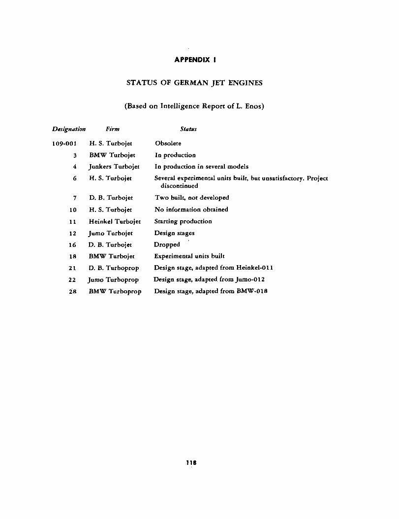
APPENDIX I
STATUS OF GERMAN JET ENGINES
(Based on Intelligence Report of 1. Enos)
Designation Firm
109-001 H. S. Turbojet
3 BMW Turbojet
4 Junkers Turbojet
6 H. S. Turbojet
7 D. B. Turbojet
10 H. S. Turbojet
11 Heinkel Turbojet
12 Jumo Turbojet
16 D. B. Turbojet
IS BMW Turbojet
21 D. B. Turboprop
22 Jumo Turboprop
2S BMW Turboprop
Stat liS
Obsolete
In production
In production in several models
Several experimental units built, but unsatisfactory. Project discontinued
Two built, not developed
No information obtained
Starting production
Design stages
Dropped
Experimental units built
Design stage, adapted from Heinkel-Oil
Design stage, adapted from Jumo-O 12
Design stage, adapted from BMW-OlS
118

APPENDIX II
INFORMATION ON GERMAN JET ENGINES
(Based on Intelligence Report of L. Enos)
jllmo-004-A Turbojet
Construction began Oct/Nov 1939 Diameter, 760 mm Length, 3800 mm Weight, 850 kg Static thrust, 840 kg Specific fuel consumption, 1.4 kg/kg-hr Six combustion chambers Eight-stage axial compressor, 20 kg/sec flow Rotational speed, 8700 rpm . One-stage turbine No nickel or chrome was used First test, Oct, 1940 First flight in Me-262 on 18 June 1942 First flight in Ar·234 in Aug 1943 40 to 50 built
jllmo-OO4·B-O Turbojet
Lighter by about 100 kg First test, Feb/Mar 1943 Only five built
jllmo-OO4·B-1 Turbojet
First two stages have been changed Diameter, 760 mm Length, 3800 mm Weight, 750 ± 30 kg Static Thrust, 900 kg at 8700 rpm Specific Fuel Consumption, 1.4 to 1.44 kg/kg-hr Air flow increased from 20 to 22 kg/sec Pressure ratio increased from 3.2 to 3.5 First test, May/June 1943 First flight in Me-262 VG, first one with landing gear, Sept/Oct 1943 40 to 50 of 0 series Oct 1943 to Jan/Feb 1944 Production series, Feb/Mar 1944 Dec 1944, production 500 to 600 per month
jllmo-OO4-B-4 Turbojet
Like B·t with air-cooled turbine blades B·4 production in Dec, about 200 To Apr 1945, 5000 to 6000 B·l and B·4 built
119
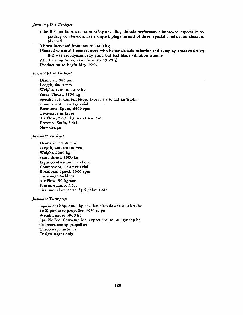
~unfo-004-lJ-4 JrurhoJet
Like B-4 but improved as to safety and like, altitude performance improved especially regarding combustion; has six spark plugs instead of three; special combustion chamber planned
Thrust increased from 900 to 1000 kg Planned to use B·2 comprt:ssors with better altitude behavior and pumping characteristics;
B-2 was aerodynamically good but had blade vibration trouble Afterburning to increase thrust by 15·20 % Production to begin May 1945
/unfo,.Q04-H-4 Jrurhojet
Diameter, 860 mm Length, 4000 mm Weight. 1100 to 1200 kg Static Thrust, 1800 kg Specific Fuel Consumption, expect 1.2 to 1.3 kg/kg-hr Compressor, II-stage axial Rotational Speed, 6600 rpm Two-stage turbines Air Flow, 29-30 kg/sec at sea level Pressure Ratio, 5.5:1 New design
~unfo-012 ~urhojet
Diameter, 1100 mm Length, 4000-5000 mm Weight, 2200 kg Static thrust, 3000 kg Eight combustion chambers Compressor, II-stage axial Rof'ational Speed, 5300 rpm Two-stage turbines Air Flow, 50 kg/sec Pressure Ratio, 5.5:1 First model expected April/Mav 1945
jUnfo-022 Jrurboprop
Equivalent bhp, 6000 hp at 8 km altitude and 800 km/hr 50% power to propeller, 50% to jet Weight, under 3000 kg Specific Fuel Consumption, expect 350 to 380 gm/hp-hr Counterrotating propellers Three.stage turbines Design stages only
120

APPENDIX III
The principal characteristics oC the tunnels up to the middle oC 1943 are given in the accompanying tables. The Collowing remarks are made with regard to the various columns.
ColNmn 2
The wind tunnels are arranged according to the corresponding, Research Institute, Technical School. or Industry; and the tunnel name or designation is the one given by· the organization.
ColMmn 3
When a tunnel had undergone a major modification aCter it had already been in operation, both the year oC first operation as well as the year of the last major modification are given in the tahle.
Co/limn 4
Wind tunnels are classified either as closed return or open return. For the closed-return type the table also gives the relationship between the return circuit and the test section.
ColNmn'
This column tells whether the test section is open or closed and gives the length. By the semi closed type is understood a test section of rectangular cross section enclosed by fixed walls on two sides.
For open-throat tunnels the length of the test section denotes the distance between the planes of the nozzle discharge and collector hell entrance. For closed throats the length of the test section refers to the throat portion of essentially constant cross section immediately following the nozzle.
Notation is made in this column whenever the tunnel is of the variable-density type.
ColNmn 6
This column gives the principal characteristics of the nozzle. The shape oC the nozzle discharge cross section is given in the small sketch. Also given are the dimensions of the nozzle discharge in meters, the length of the nozzle in meters, and the contraction ratio "C," namely the area ratio between the upstream and downstream section.
The length of the nozzle includes transition portions or fairing when used. If the transition portions are unnecessarily long then the .ength of the nozzle from the start of the contraction to the narrowest cross section is also given in parenthesis.
ColNmn 7
For low-speed tunnels, under 100 m/sec, the: values of maximum velocity for a '-min duration are given with the assumption of a normal wing model in the test section. The figures in parenthesis refer to the maximum values for continuous operation.
For high-speed tunnels the maximum Mach number with no model in place is given in full figures. The values in parenthesis are based on a blocking of the throat corresponding to 1 % in area.
121
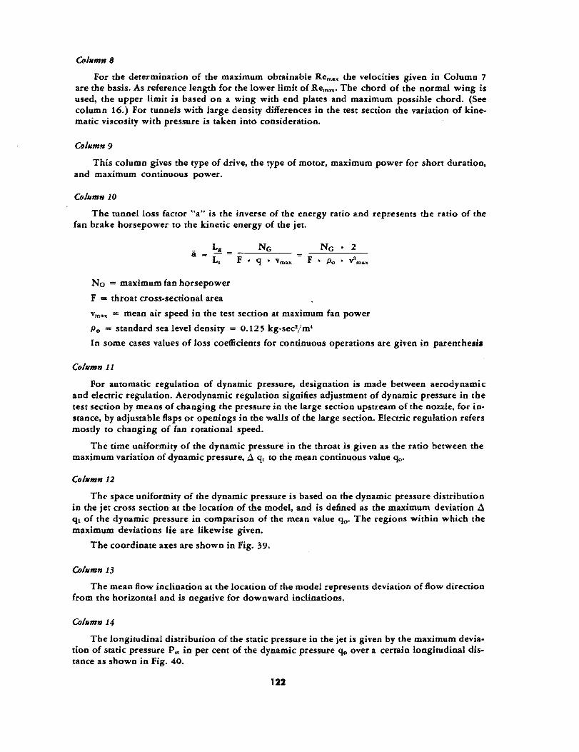
CO/limn 8
For the determination of the maximum obtainable Rem." the velocities given in Column 7 are the basis. As reference length for the lower limit of Remal(' The chord of the normal wing is used, the upper limit is based on a wing with end plates and maximum possible chord. (See column 16.) For tunnels with large density differences in the test section the variation of kinematic viscosity with pressure is taken into consideration.
CO/limn 9
This column gives the type of drive, the type of motor, maximum power for short duration, and maximum continuous power.
CO/limn 1Q
The tunnel loss factor "an is the inverse of the energy ratio and represents the ratio of the fan brake horsepower to the kinetic energy of the jet.
No = maximum fan horsepower
F = throat cross-sectional area
F • q • vma" F • Po • v1max
vma" = mean air speed in the test section at maximum fan power
Po = standard sea level density = 0.125 kg-sec2/m4
In some cases values of loss coefficients for continuous operations are given in parenthesis
CO/limn 11
For automatic regulation of dynamic pressure, designation is made between aerodynamic and electric regulation. Aerodynamic regulation signifies adjustment of dynamic pressure in the test section by means of changing the pressure in the large section upstream of the nozzle. for instance, by adjustable flaps or openings in the walls of the large section. Electric regulation refers mostly to changing of fan rotational speed.
The time uniformity of the dynamic pressure in the throat is given as the ratio between the maximum variation of dynamic pressure, ~ q, to the mean continuous value qo.
CO/limn 12
Th« space uniformity of the dynamic pressure is based on the dynamic pressure distribution in the jet cross section at the location of the model, and is defined as the maximum deviation ~ ql of the dynamic pressure in comparison of the mean value qo. The regions within which the maximum deviations lie are likewise given.
The coordinate axes are shown in Fig. 39.
CO/limn 13
The mean flow indination at the location of the model represents deviation of flow direction from the horizontal and is negative for downward indinations.
CO/limn 14
The longitudinal distribution of the static pressure in the jet is given by the maximum deviation of static pressure Pst in per cent of the dynamic pressure qo over a certain longitudinal distance as shown in Fig. 40.
122
CO/limn 15
The critical Reynolds number RK is a measure of the tunnel turbulence. It is determined in general by measurement of sphere drag as a function of the Reynolds number, or by determination of the static pressure on the rear portion of the sphere as a functioo of the Reynolds number. For drag measurements, the critical Reynolds number is defined as the value corresponding to a drag coefficient Cd = 0.3. Rear static pressures and the sphere diameter in millimeters are also given.
CO/limn 16
In this column appear not only normal values of chord and span for model wing tests, but also the maximum values which have been tested. The values in parenthesis represent the maximum possible chord of a wing with end plates.
CO/limn 17
The type of model suspension system generally used in the respective tunnels is shown in small sketch. In some cases special suspension systems are indicated.
CO/limn 18
In this column the measuring principles of the individual balances are indicated as well as the number of components which can be measured.
Co/limn 19
General remarks.
123

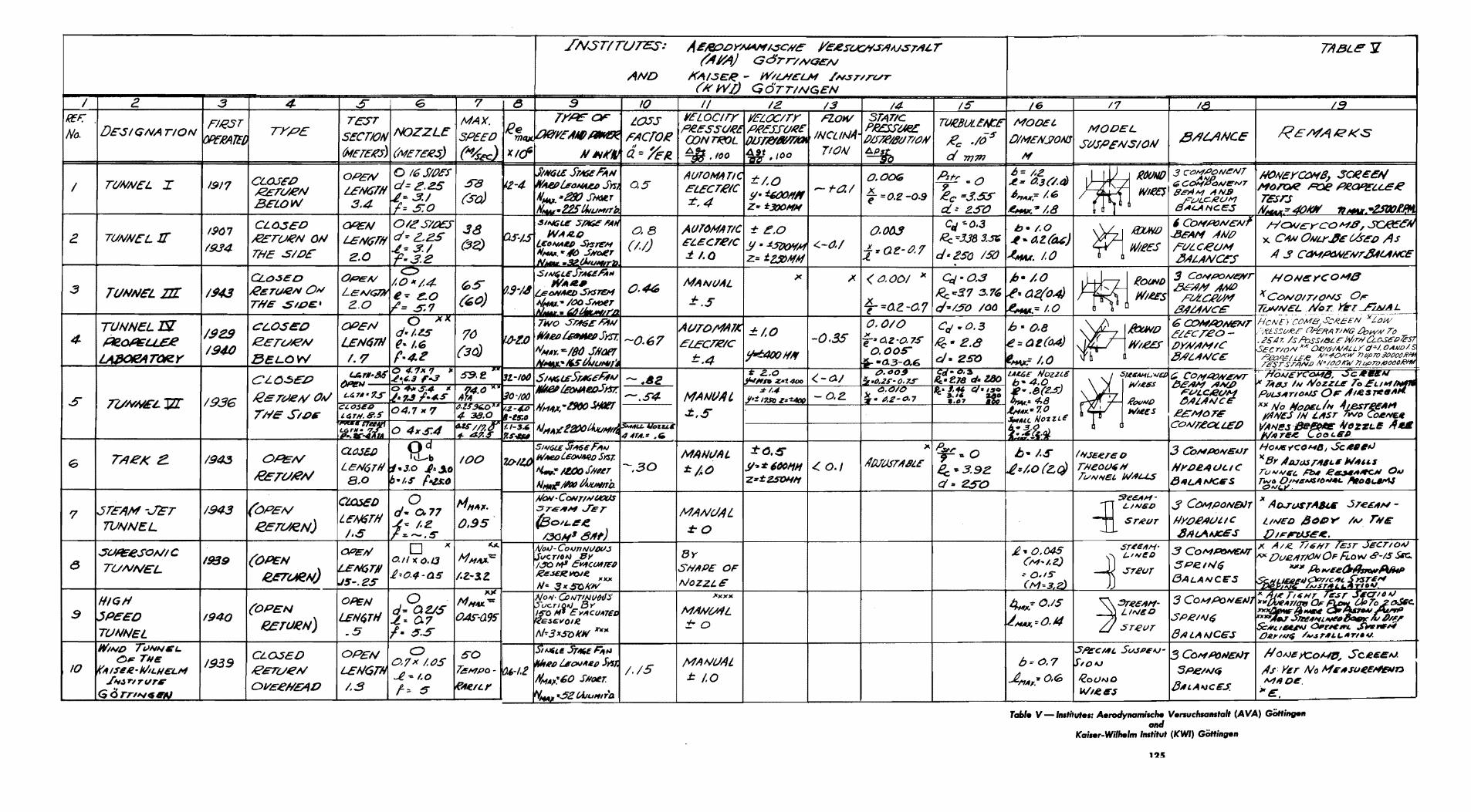

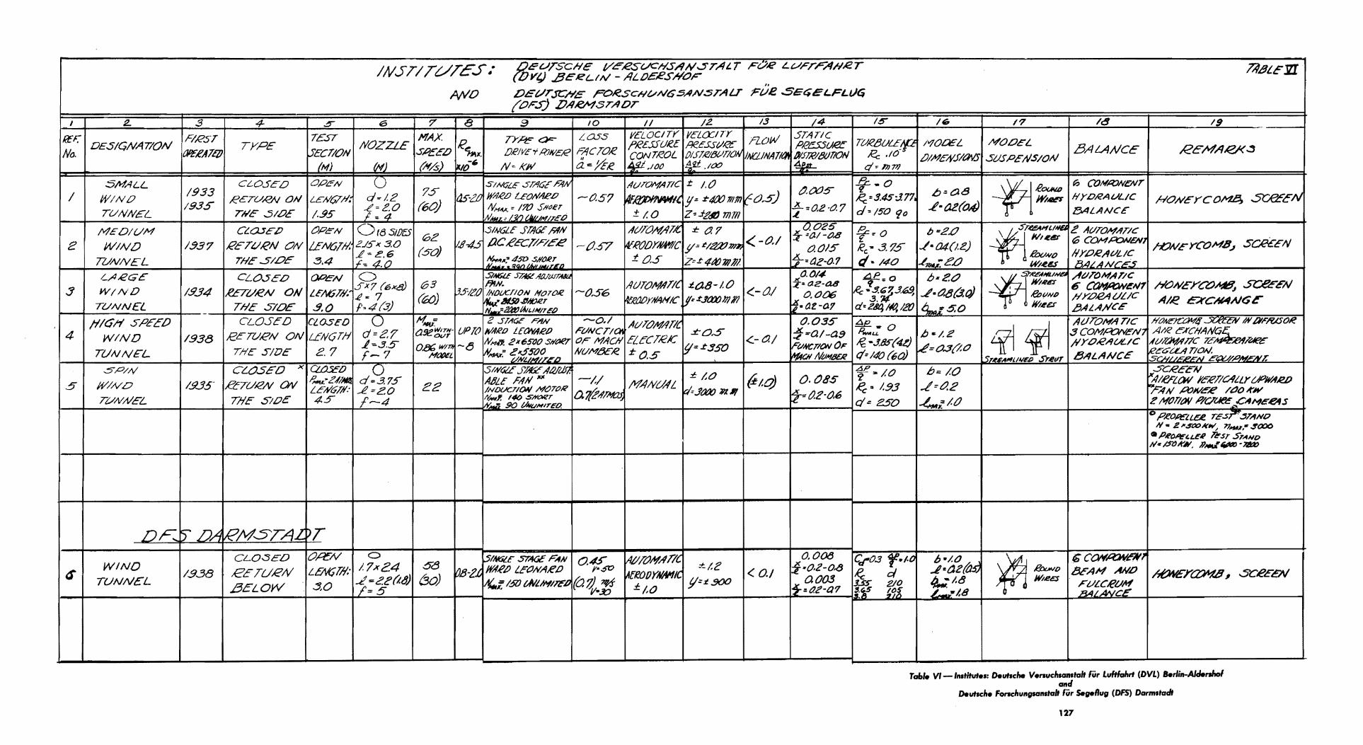

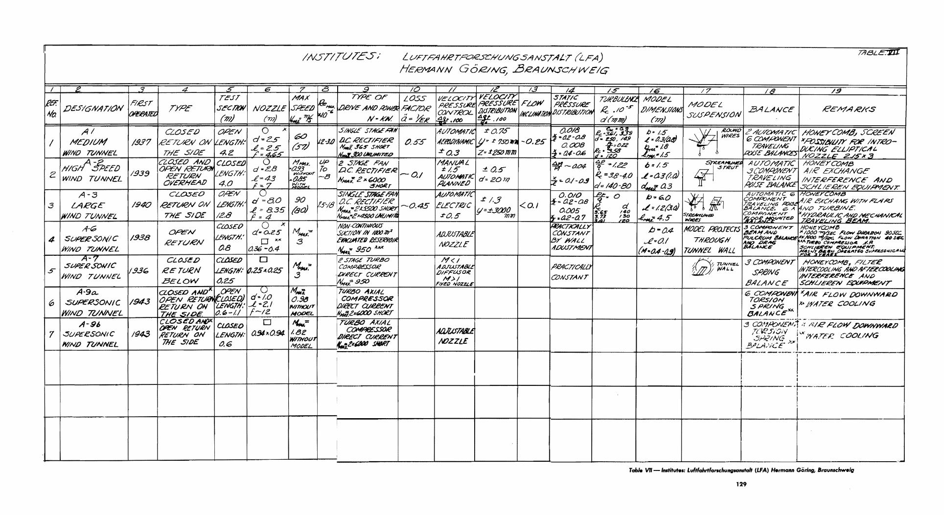


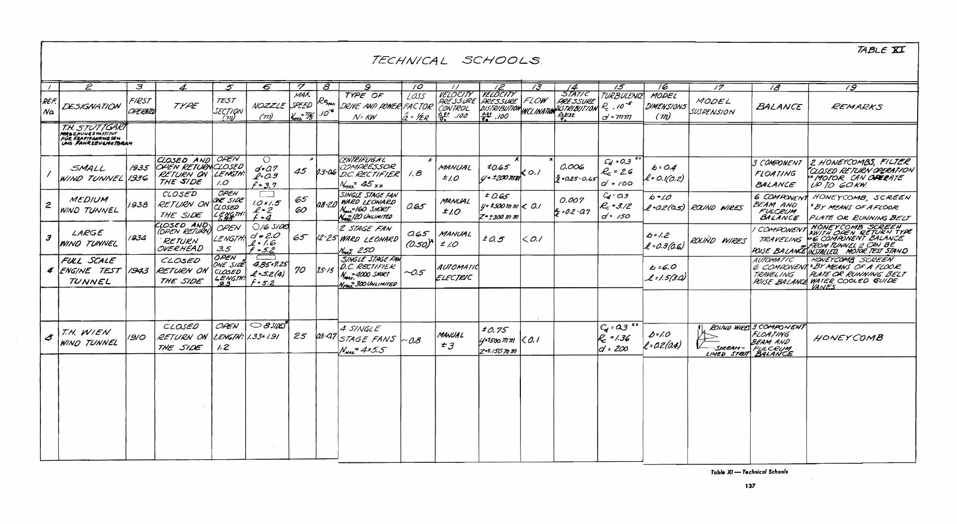

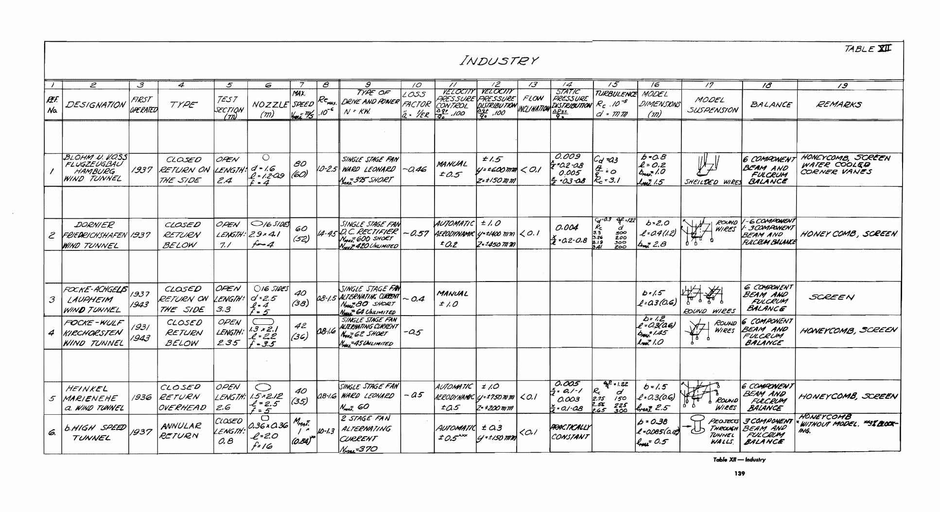


APPENDIX IV
ORGANIZATION OF THE W ASSERBAUVERSUCHSANST ALT AT KOCHELSEE
Director, Dr. Rudolph Herrmann
Deputies: Dr. Herman Kursweg, Technical
Dr. Herbert Graf, Administrative
Dr. Gerhard Eber, Business Representative
A. Research Division, Dr. Hermann Kursweg
1. Aerodynamic Measurements
2. Basic Aerodynamic Research
3. Mathematical Department
B. Electrotechnical Division, Heinrich Ramm
1. Electrical measurements: Sigfried Hoh
a. R-ray apparatus, Gottfried Arnold
b. Electromagnetic three-component balances, Gottfried Arnold
c. Electromagnetic pressure capsules, Gottfried Arnold
2. Electrical Operation
C. Technical Development Division, Hans Gessner
1. Wind-tunnel construction and mechanical equipment
a. Design
b. Fabrication
D. New Wind-Tunnel Division, Dr. Gerhard Eber
This division is in charge of design and erection of the new 1 x I-m wind tunnel, M= 7, 76,000 hp.
1. Scientific Questions; Karl Heinrich Grunewald
2. Test Section, Gunther Dellmaier (this group handles test section, diffuser, three component balances, Schlieren equipment, and coordinates fabrication with Firma Dingler inZweibrucken)
3. Machinery (this group is in charge of the turbines, vacuum pumps, coolers. valves, drying system, etc.)
4. Electrical Depactment
5. Miscellaneous Equipment
E. Administrative Division, Dr. Herbert Graf
141


PART IV
JAPAN'S AERONAUTIC RESEARCH PROGRAM AND ACHIEVEMENTS
By
FRANK W. WILLIAMS
LT. COLONEL, A. C.
The information in this report was derived through personal observation and interview by the members of the Scientific Advisory Group, AAF.listed below, while in Japan, and from ATIG reports of other persons at· tached to ADVON FEAF. The names of the principal reports prepared by this group are reported at the end of this paper.
AAF Scientific Advisory Personnel:
DR. F. L. W A TTENDORF
DR. W. H. PICKERING
LT. COLONEL F. W. WILLIAMS
MAJOR T. F. W ALKOWICZ


PART IV
JAPAN'S AERONAUTIC RESEARCH PROGRAM
AND ACHIEVEMENTS
DECEMBER 1945
INTRODUCTION
Up until the close of the war Japan was endeavoring to overtake us in the research and development of all types of scientific weapons. In some few cases they were closely parallel to us, but in most phases they were far behind us.
Much of the fault for lagging behind can be blamed on the lack of cooperation between the Army, the Navy, and the civilian scientists. The two services appear to have been very jealous of each other's achievements to the point where they would withhold from each other information concerning their own or enemy equipment, which information would have been of great value to the other.
Neither of the services would admit that any of the "brains" of the nation might be found among the civilians. The scientists of schools and other civilian research organizations were either not utilized at all or were assigned to very minor problems. Questioning of the various scientists brings out the fact that the average person in charge of research in the Army or Navy was not as brilliant as the average of the civilian scientists. There were exceptions of course. .
Some person or persons in authority in the services conceived the idea that elaborate laboratory facilities would lead to superior developments. The wind tunnels and other research equipment were therefore multitudinous. Some of the wind tunnels had never been operated because the builders neglected to assure themselves of an adequate power supply before building.
Toward the end of the war an organization was formed similar to our NDRC and with similar purpose in view. However, it was organized too late and even then was opposed by the Army and Navy, hence was ineffective.
Difficulty was experienced in· finding Japanese reports. They were all destroyed per imperial edict about l' August 194'. Many ofthe important recent reports have been rewritten at our request by the scientists concerned. In some cases copies of the original reports that had been "overlooked" when aU were burned were produced when scientists were directed to rewrite certain experiments.
151
HIGH-SPEED FLIGHT
That the Japanese were striving toward high-speed flight is evidenced by number of high-speed wind tunnels they built, many of them being of the supersonic type. Data on the size and speed of a few of these is shown graphically in Figs. 47 and 48.
ArrowheaJ Wing.
All Japanese questioned denied having any knowledge of swept-back wings. However, a wind-tunnel model with a 32° sweep back was found at the First Naval Air Technical Arsenal at Yokosuka.
No test data or reports were found in the files.
High-Speed Propeller Research.
Propeller tests at a tip speed of M = 1.2 were made in the 1.6-m wind tunnel at the Tokyo Imperial University. The propellers tested were not of a radical design like the swept-back tips found in Germany. The tests showed good thinking and the results were qualitatively good. There was no indication that either of the armed services used the information.
Boundary Layer Control.
Professor Fukatsu of the Tokyo Imperial University had been engaged in basic research on boundary layer control for five years. It was his belief that no one else in Japan had worked on boundary layer problems nor had any experimental planes been built. Further investigation revealed that he was only one of several men working on this problem for the Japanese Navy and that the Navy had initiated the development of a large Kawanishi flying boat with boundary layer control equipment installed.
A report covering his entire work is being made available to A-2. It is an excellent contribution to the fund of basic knowledge on this subject and should be widely circulated.
Laminar Flow Wings. Laminar flow wings were the subject of research in Japan some length of time
before they were known in this country. At about the time when the NACA was conducting secret research on this type wing the Japanese published and circulated a very thorough and good report on their results.
Tokyo Imperial University was developing a family of laminar flow airfoils denoted as the LB Series. In this designation the letters "LB" stand for light blue, the school colors. Work was also under way at Tokyo Imperial University to develop high-speed airfoils for improved performance at high Mach numbers.
Flight Data.
Flight characteristics of five of the speediest of the experimental Japanese airplanes are shown in Fig. 49. It will be noted that none of them are up to the standards of the German or American planes.
GUIDED MISSILES
The Japanese had put much effort into developing heat-homing devices intending to apply them to bombs, boats and airplanes.
152
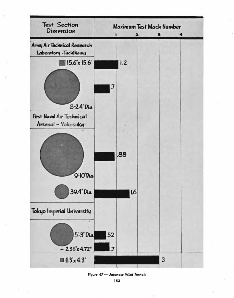

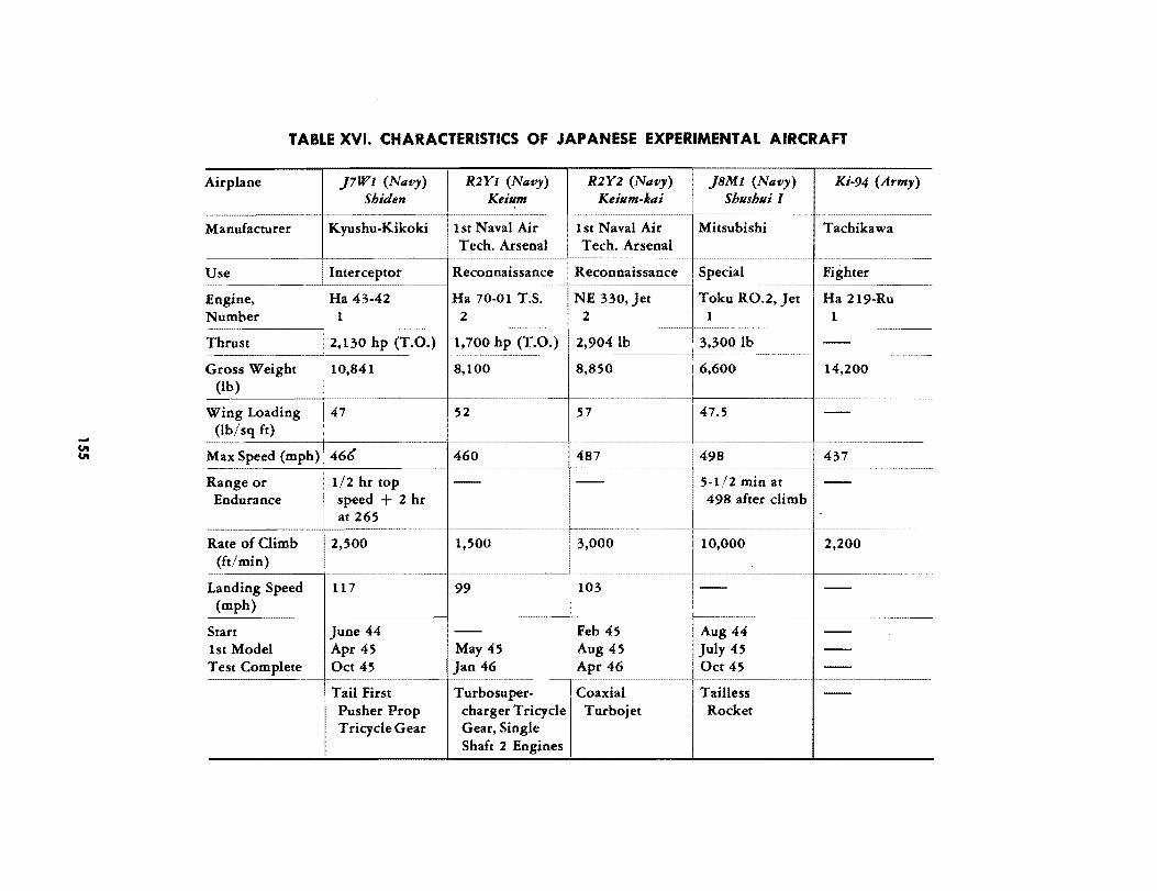
TABLE XVI. CHARACTERISTICS OF JAPANESE EXPERIMENTAL AIRCRAFT
Airplane }7Wl (Navy) R2Yl (Navy) R2Y2 (Navy) }8Ml (Navy) Ki-94 (Army) Shiden Keillm Keillm-klli Shllshlli I
Manufacturer K yushu-Kikoki 1st Naval Air 1st Naval Air Mitsubishi Tachikawa Tech. Arsenal Tech. Arsenal
Use Interceptor Reconnaissance Reconnaissance Special Fighter
Engine, Ha 43-42 Ha 70-01 T.S. NE 330, Jet Toku RO.2, Jet Ha 219-Ru Number 1 2 2 1 1
Thrust 2,130 hp (T.O.) 1,700 hp (T.O.) 2,9041b 3.3001b --!m Gross Weight 10,841 8,100 8,850
16,600 14,200
(lb)
Wing Loading ! 47 52 57 1
47.5 --(lb/sq ft)
-----------------
Max Speed (mph) ~ 466 460 487 498 437 -------- -----
11/2 hr top Range or -- -- 5·1/2 min at --Endurance i speed + 2 hr 498 after climb I
i at 265 --------------- ---------- ------
Rate of Climb 2,500 1,500 3,000 10,000 2,200 (ft/min)
Landing Speed 117 99 103 -- --(mph) I
------------ -Start June 44 -- Feb 45 Aug 44 --1st Model Apr 45 May 45 Aug 45 July 45 --Test Complete Oct 45 Jan 46 Apr 46 Oct 45 --
------------
Tail First Turbosuper- Coaxial Tailless --Pusher Prop charger Tricycle Turbojet Rocket Tricycle Gear Gear, Single
Shaft 2 Engines

The first eight types tested gave very poor results. The ninth model was to have been ready for test in September, 1945. Nothing new was involved.
No new or valuable designs were discovered in the field of television-guided missiles. The men working on this claimed that they did not have available to them any information on foreign developments.
A German report states that the Japanese had been given technical information on the V-bombs in March of 1945, although the Germans thought that the Japanese had previously secured the information in some manner.
JET PROPULSION
The Japanese Army and Navy both conducted research on liquid fuels for jet engines. Their reasons were multiple: to replace solid fuels in rockets; to increase the range of rockets; and to develop a jet aircraft engine.
According to a German report three sets of plans of the Me-162 and Me-163 were sent by three different submarines from Kiel to Japan between 7 November 1944 and 1 March 1945. The Germans are also reported to have shipped a disassembled jet plane by submarine to the Japanese. The Shushui J8MI was the Navy's jet plane development.
The Shushui, a tailless plane driven by one jet, was a product of the Mitsubishi Company. It was started in August, 1944 and the test model crashed on its first flight in mid-1945.
The design was based on the Me-163 and the calculated top speed at 32,500 ft altitude was 496 mph. Rate of climb was calculated at about 10,000 ft/min. The duration of flight after the climb to 32,500 ft was 5-1/2 min.
Because of the difficulty of manufacturing, storing, and shipping large quantities of H202 (hydrogen peroxide) the Japanese tried other fuel combinations. The most successful of these combinations was HNOa and C2H50H (nitric add and alcohol), with a cordite ignitor. They daim to have developed this without any outside information or assistance.
Both the Army and Navy planned to develop long-range rockets but had not proceeded very far. The Navy had a 20-cm rocket with a maximum range of 13 miles. The Army had conducted a few experiments on chamber pressures.
GAS TURBINE PROPULSION
Theoretical studies of the ramjet were started in 1938 at Tokyo Imperial University. Some tests were made on models in low-speed tunnels, but little interest was shown in the project by the Japanese Government.
The Japanese Navy built a model gas turbine on the free-piston principle in 1941, but nothing further was done. Several experimental turbojet units were under development when the first cross-sectional drawing of the German BMW-003 was received, also in 1941. At once aU Japanese gas-turbine projects were dropped and a feverish
156
attempt was made to copy the BMW.003 engine. The Navy version of this copy was the NE.20, which made its first successful flight in the twin.engined Kikka in August, 1945.
GLIDER RESEARCH
The Glider Research Institute at Kyushu Imperial University was founded in September, 1943. This Institute did not publish any of its reports due to the shortage of paper and because all of their printers had been dratted. However, some interesting theoretical work had been done on the longitudinal and lateral stability of glider.tow. plane combinations. Very little work of this nature has been done in this country and the Japanese investigation may prove to be.of some value.
ELECTRONICS
RaJar.
The Japanese had some radar equipment operating on a wavelength as short as 10 cm, but with very low power output. They received a German "Wurzburg" radar in 1943 but were unable to copy it by the end of the war. On the whole their radar equipment was very inferior.
The two most interesting things in Japanese radar are: (a) the "Doppler fence" around Tokyo; and the circularly polarized "unit horn" radar system.
A Doppler radar system was proposed by Okabe about 10 years ago, and, al· though their main interest shifted to conventional pulse radar, the Doppler fence was built and used. It consisted of a ring of stations transmitting more or less sharply defined beams. An indication was received whenever a plane crossed one of these beams. The Japanese said that this system served as a useful check on their pulse radar.
The circularly polarized radar system was devised as a means of solving the problem of using a common antenna for transmitting and receiving, without using TR tubes as we do. Although the system did not work well in the field, it has interesting possibilities and may well become standard for microwave radar.
RaJar Count.rm.asure ..
Japanese developments consisted of noise and CW jammers on the longer wave· lengths. Work was being done on tubes suitable for microwave jammers but these were not in use. The Navy was attempting to develop an antiradar coating suitable for submarines and reportedly had some success with the usual powdered iron, graphite, combination. No work on means of countering window was discovered.
IFF. The most interesting point about Japanese IFF systems is that the Army and Navy
developed systems independently which operated on different frequencies, and the lack of coordination between the services was such that neither one could identify the other's airplanes. Eventually the problem was more or less solved by installing duplicate ground equipment.
157

Navigation Aids. The japanese discovered our Loran system and quickly set up a similar system
for their own use. It had the interesting feature that the pulses were generated at a master station which was connected by VHF links to the two transmitting stations.
Vacuum Tuhe ..
For ordinary use the japanese copied American tubes even to the extent of using the same type number. However, in the microwave field their designs are startingly . novel. Magnetron research originated in japan and a wide variety of design can be found. In no case, however, did they produce peak powers comparable to ours. Very large CW magnetrons were built for their "Death Ray" and "Shell Exploder." Their most successful magnetrons followed the ~ame design principles as ours. They built a variety of velocity modulation and Barkhausen tubes none of which are of great interest, although some were used in the field.
Proximity Fu ....
The japanese did not have a large number of projects such as was found in Germany, but they did have a photoelectric fuse for bombs, in the field. This was designed to explode the bomb about 20 or 30 ft above the ground and apparently worked quite well. It transmitted a beam of light which was chopped by a motor-driven shutter, and when the intensity of the reflected light reached a certain value the bomb was detonated.
She" Exploder. An analagous device to the proximity fuse was designed to explode AA shells at
the correct instant. The shells were to be equipped with a simple radio receiver, and a radio beam was to be focused on the target. When the shells entered the beam, the energy picked up by the receiver would be sufficient to operate a detonator.
The receiver was to be a simple dipole and crystal detector and hence a very intense radio beam was required. For this purpose high-power microwave magne. trons, and a large parabolic reflector were built at the Shimada laboratory of the Second Naval Technical Institute.
"'frared. japanese work in this field was greatly inferior to German. Some work was done
with signalling and some on noctovision. There was also a heat.homing bomb. De· tectors used were chiefly thermocouples and bolometers, with some attempt to develop more sensitive thermocouple alloys.
Figltter Control.
The japanese developed an elaborate system for control of their airplanes. Each airplane carried a transmitter on the same frequency but with a different supersonic modulation. Two ground stations took bearings on the airplanes with continuously rotating antennas. These bearings were automatically reported into a central station where they were identified with each airplane. It was hoped to be able to handle 30 airplanes. However, the actual system was very cumbersome and was never put into full operation.
151

DEATH RAY
The Japanese Army had attempted the development of a death ray at its Nohorito laboratory since 1940.
The apparatus ~s it was in 1945 could kill a rabbit at 30 m distance in 10 min. The wave was projected by an ellipsoidal reflector at the focus of which was a dipole antenna fed by a CW oscillator. The experiments were tried at various wavelengths and powers.
The schedule was briefly as shown:
1940 Experiments with 3·m wave with 20·kw power.
Experiments with 20-cm wave with 30.kw power.
1941 Experiments with 2-m wave with 10-kw power.
Experiments with 20-cm wave with 50-kw power.
1942 No work.
1943 Designing of higher power oscillator.
1944 Experiments with SO-cm wave with 30-kw power.
1945 Designing of SO-cm, 300·kw power input magnetron, mounted in a 10-m diameter reflector.
This last apparatus was intended to kill a rabibt at 1000 m. The effect of the ray was to cause brain cell destruction. It will be noted in these experiments that it is necessary for the subject to be held stationary at the focus of a second ellipsoidal reflector for some length of time. Monkeys made poor subjects because they would not remain stationary. It would obviously be impossible to use this complete technique against a human enemy.
However, the experiments indicate progress and if continued probably would lead to the development of a death-dealing ray reaching greater distances.
BALLOON BOMBS
The Japanese released about 9000 of their paper balloon bombs against the United States. They admitted that the weapon was chiefly a propaganda weapon and stopped making releases in April, 1945.
The records of the launchings were claimed to be destroyed and hence much valuable meteorological information is lost.
Incendiaries and high explosives were the only pay loads used, with the later bombs carrying only incendiaries.
All balloons were released from sites along the northeastern coast of Japan. As many as 150 were released on a single day. Maximum rates were achieved in February and March, 1945.
This weapon is of interest for two reasons: (1) the length of flight and the 100· mph average wind velocities encountered at 30,000 ft; (2) the construction of the balloon and the control mechanism enabling it to stay aloft for three or four days.
159
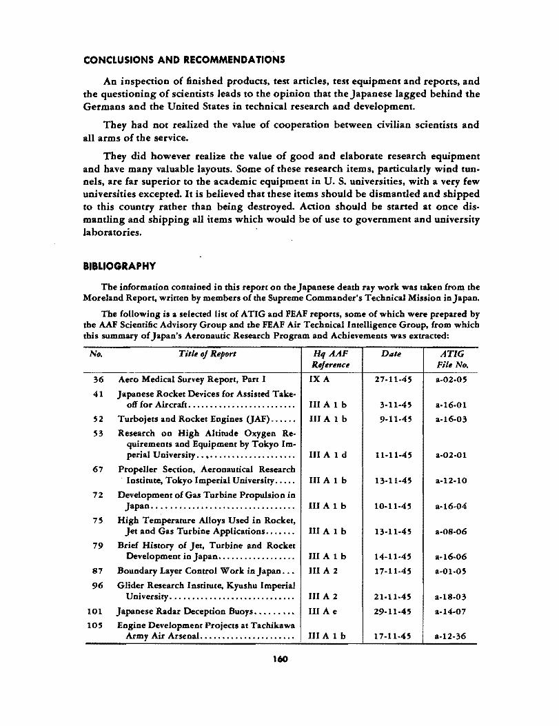
CONCLUSIONS AND RECOMMENDATIQNS
An inspection of finished products. test articles. test equipment and reports. and the questioning of scientists leads to the opinion that the Japanese lagged behind the Germans and the United States in technical research and development.
They had not realized the value of cooperation between civilian scientists and all arms of the service.
They did however realize the value of good and elaborate research equipment and have many valuable layouts. Some of these research items. particularly wind tunnels. are far superior to the academic equipment in U. S. universities. with a very few universities excepted. It is believed that these items should be dismantled and shipped to this country rather than being destroyed. Action should be started at once dismantling and shipping all items which would be of use to government and university laboratories.
BIBLIOGRAPHY
The information contained in rbis report on the Japanese death ray work was t~en fro~ the Moreland Report, wrirren by members of the Supreme Commander's Technical Mission in Japan.
The following is a selected list of ATIG and FEAF reports. some of which were prepared by the AAF Scientific Advisory Group and the FEAF Air Technical Intelligence Group, from which this summary of Japan's Aeronautic Research Program and Achievements was extracted:
No. Title oj Report HqAAF Date ATIG Rejerence File No.
36 Aero Medical Survey Report, Part I IXA 27·11·45 a-02-05
41 Japanese Rocket Devices for Assisted Take· off for Aircraft ....................•.... III A 1 b 3-11·45 a·16·01
52 Turbojets and Rocket Engines OAF) ...... III A 1 b 9·11·45 a·16·03
53 Research on High Altitude Oxygen Re· quirements and Equipment by Tokyo Im-perial University .. ~ .................... III A 1 d 11·11·45 a·02·01
67 Propeller Section, Aeronautical Research . Institute. Tokyo Imperial University ..... III A 1 b 13·11·45 a-12-10
72 Development of Gas Turbine Propulsion in Japan ... ..................................................... III A 1 b 10-11·45 a-16-04
75 High Temperature Alloys Used in Rocket, Jet and Gas Turbine Applications ...•... III A 1 b 13·11·45 a·08·06
79 Brief History of Jet. Turbine and Rocket Development in Japan .................. III A 1 b 14-11·45 a·16·06
87 Boundary Layer Control Work in Japan ... III A 2 17-11-45 a-Ol·05
96 Glider Research Institute, Kyushu Imperial University ................•.•.....••... III A 2 21·11·45 a-18·03
101 Japanese Radar Deception Buoys ..•..•... III A e 29·11·45 a-14-07
lOS Engine Development Projects at Tachikawa Army Air Arsenal ..•................... III A 1 b 17-11·45 a·12-36
160
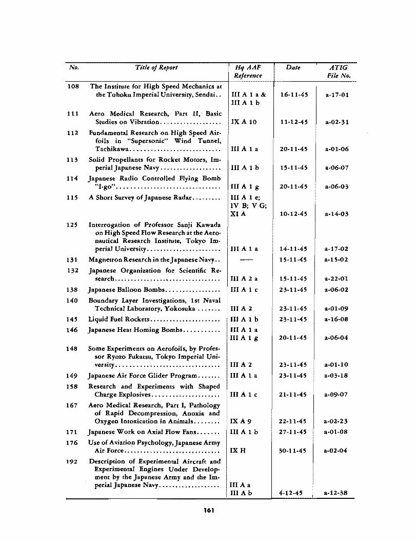
No.
108
111
112
113
Title oj Report
The Institute fnr High Speed Mechanics at the Tohoku Imperial University, Sendai. .
Aero Medical Research, Part II,· Basic Studies on Vibration .................. .
Fundamental Research on High Speed Airfoils in "Supersonic" Wind Tunnel, Tachikawa ....•.......................
Solid Propellants for Rocket Motors, Im-perial Japanese Navy .................. .
114 Japanese Radio Controlled Flying Bomb
HqAAF Rejerence
III A 1 a &
III Alb
IXA 10
III A 1 a
III Alb
"I-go" . . • . . . . . . . . . . . . . . . . . . • . . . . . . . . . . III A 1 g
115
125
131
132
138
140
145
146
A Short Survey of Japanese Radar ........ .
Interrogation of Professor Sanji Kawada on High Speed Flow Research at the Aeronautical Research Institute, Tokyo Im-perial University .............•.........
Magnetron Research in theJapaneseNavy ..
Japanese Organization for SdentHic Re· search ............... " ............... .
Japanese Balloon Bombs ................ .
Boundary Layer Investigations, lst Naval Technical Laboratory, Yokosuka ...... .
Liquid Fuel Rockets ..................... .
Japanese Heat Homing Bombs .......... .
148 Some Experiments on Aerofoils, by Profes-sor Ryozo Fukatsu, Tokyo Imperial Uni-
III Ale; IV B; V G; XIA
III A 1 a
III A 2 a
III Ale
III A 2
III Alb
III A 1 a III A 1 g
versity. . . . . . . . . . . . . . . . . . . . . . . . . . . . . . . . III A 2
149
158
167
171
176
192
Japanese Air Force Glider Program ...... .
Research and Experiments with Shaped Charge Explosives ..••.................
Aero Medical Research, Part I, Pathology of Rapid Decompression, Anoxia and Oxygen Intoxication in Animals ....... .
Japanese Work on Axial Flow Fans ...... .
Use of Aviation Psychology,Japanese Army Air Force •..•.....••...................
Description of Experimental Aircraft and Experimental Engines Under Development by the Japanese Army and the Im-perial Japanese Navy .................. .
161
III A 1 a
III A 1 c
IXA9
III Alb
IXH
III A a III A b
Date
16-11-45
11·12-45
20-11-45
15-11-45
20-11-45
10-12-45
14-11-45
15-11-45
15-11-45
23-11-45
23-11-45
23-11·45
20-11·45
23·11·45
23·11·45
21·11·45
22-11-45
27-11.45
30-11·45
4·12-45
ATIG File No.
a·17·01
a·02·31
a·Ol-06
a-06-07
a·06·03
a·17-02
a-15-02
a·22-01
a·06·02
a-Ol·09
a-16·08
a·06·04
a·Ol·l0
a·03·18
a·09·07
a·02-23
a-0l·08
a-02·04
a·12-38
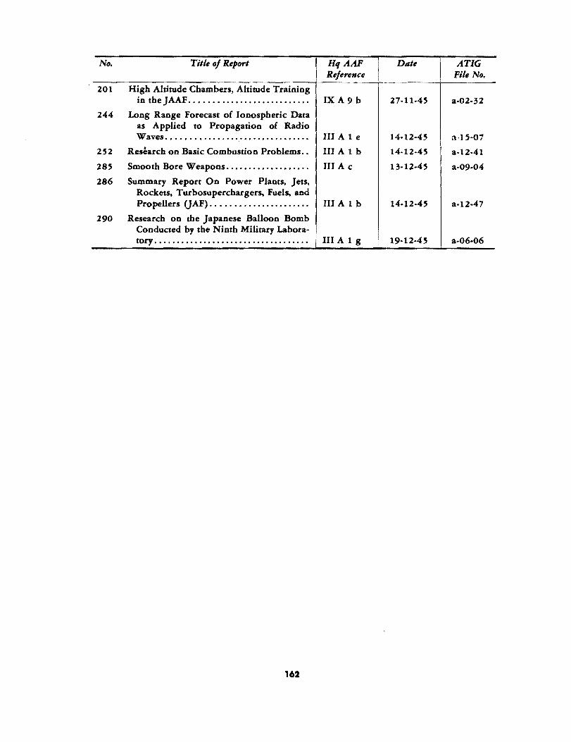
No.
201
244
252
285
286
290
Title of Report
High Altitude Chambers, Altitude Training in the JAAF ..........•................
Long Range Forecast of Ionospheric Data as Applied to Propagation of Radio Waves .•..•..•........ , ............... .
Research on Basic Combustion Problems ..
Smooth Bore Weapons ..•.•........••.•..
Summary Report On Power Plants, Jets, Rockets, Turbosuperchargers, Fuels. and Propellers (JAF) .................... ..
Research on the Japanese Balloon Bomb Conducted by the Ninth Military Labora-tory .......••.•.••••.........•..•..•...
162
HqAAF Reference
IXA 9 b
III Ale
III Alb
III A c
III Alb
III A 1 g
I I
Date
27-11-45
14-12-45
14-12-45
13-12-45
14-12-45
19-12-45
ATIG File No.
a-02-32
a-15-07
a·12-41
a·09-04
a-12-47
a-06-06

PART V
REMARKS ON THE JAPANESE WAR TECHNICAL EFFORT
By
DR. F. ZWICKY


PART Y
REMARKS ON THE JAPANESE WAR TECHNICAL EFFORT
DECEMBER 1945
Both the German and the Japanese war technical efforts have by now been evaluated by a great number of scientific and technical specialist teams. From our less than three weeks' tour of Japan, not too much can be added by way of specific information not already available. However, the following more basic observations, with a bearing on the morphology of the past war and possible wars to come, may be of interest.
In winning a war, the victor is only too likely to assume that he is superior to the vanquished in every respect, not only materially, but also intellectually, ethically, and culturally. It is not our intention, here, to go into vistas as wide as these although historically they may clear up such puzzling facts as a people having in a very real sense lost a war in spite of having materially won it. However, already within the war technical effort in the conventional sense, three essential aspects may clearly be distinguished. These aspects are: (a) the weapons, equipment, materials, and men which a people actually threw into combat; (b) the weapons, equipment, and the new materials and chemicals which were under development in research laboratories and pilot plants. as well as the men in course of training for new practices and new methods of com bat; (c) the intellectual potential and intrinsic technical skill of a people, which may be very strong. but for various reasons may not have had a chance of realization.
It is obvious that, since both Germany and Japan lost the war, these countries were on the whole inferior to the United Nations as far as the items enumerated in point (a) are concerned. We say, on the whole, because their equipment in many respects was very good and .might have sufficed to win the war for them, had they not forfeited possible victory mostly through fatal strategic and political mistakes of their leaders. At any rate, it should be kept in mind that not only Germany, but perhaps even more so Japan, was impressive on the basis of actual equipment used in combat, provided the comparison is made on the basis of population, size of the country, natural resources, and potential industries available.
However, we are concerned here mostly with the items mentioned under (b) and (c), since the proper evaluation of these items appears to us of vital importance for a realistic outlook on future preparedness. Anticipating our conclusions, we may state that concerning these items (b) and (c), in which the Germans were very impressive, the Japanese are also more impressive than commonly is believed. Taking a few specific technical fields, the following observations may serve as an illustration:
165

In the field of jet propulsion, in ",hich the awakening of the United Nations has been lamentably and pitifully slow, the Japanese had a sound outlook.
The Japane~e themselves developed solid-propellant rocket motors, as well as the necessary solid propellants. Among these propellants, combinations of nitroglycerin, nitrocellulose, and nitronaphtha1ene are of considerable interest. It is also remarkable that the Japanese seem to have developed these propellants without any appreciable number of motor blows or other failures, such as have constantly attended solidpropellant development in the United States and in Great Britain.
Liquid propellants of the type H 20 2 (as monopropellant) and H20! plus hydrazine hydrate, were taken over from the Germans, but the necessary jet motors for fighter planes were developed independently and with such speed as to make our own developments appear in a less optimistic light.
Remarkable copy work was done on turbojets and superchargers, inasmuch as one or two photographs of drawings of the Jumo-004 engine and a casual visit of a few naval officers to Swiss factories provided enough incentive and information for the Japanese s}'eedily and successfully to design, construct, and test engines of the type mentioned.
Aeroduct motors (athodyd, ramjet) were experimented with at an earlier date than in the United States.
Rocket-propelled missiles were visualized and experimented with at an earlier date than in the United States. In conjunction with these developments, supersonic wind tunnels were instaHed several years in advance of the construction of similar equipment in the United States. Also, intricate optical instrumentation (Suhara's movie camera with 50,000 frames per second), as well as various types of measuring apparatus, were developed for the investigation of missiles and jets of very high speeds.
Hot and fast jets as instruments of destruction were developed to a remarkable degree by the Japanese, through the investigation of the kinematic burning and detonation characteristics of solid explosives. These investigations resulted in the suc-. cessful construction of huge hollow-charge war heads (1100 cm diam), which in air produce a jet over 3000 ft long (initial jet velocity ca. 16,000 ft/sec), whose tremendous destructive power was demonstrated by their action on four successive layers of reinforced concrete (thickness 50 cm, 50 cm, 100 cm, 100 cm, with air spaces of 3 m in between). This war head, which was intended for general use against warships, delivered by Baka, Kamikaze, or other means, could no doubt be made a terrifying and effective weapon. Shaped charges were also intended for use in antitank mines, bombs, rockets, etc.
The Japanese effort to move research and production underground, although initiated too late, is also very impressive, as demonstrated by the vast subterranean installations at the Yokosuka Naval Base, which were built within a few months.
In this connection, it is important to point out that as a consequence of events in World War II, not less thail three domains begin to delineate themselves sharply on the horizon as battlefields of future wars. These domains are: (1) the inside of the earth's crust and of the earth as a whole; (2) the Arctic regions; and (3) extraterrestrial space. It will be wise to prepare for all-around means to control activities in these little-charted domains.
166

Least investigated by technical specialist teams, or rather not investigated at all, is the intrinsic mental potential of the vanquished peoples. In fact, it is rather terrifying to notice among many technical men a provinciality, coupled with wishful thinking, which can only result in disaster if the democracies might conceivably have to face more astute enemies than those of the immediate past. To give an example:
It is stated in the official Smyth report on the development of the atomic bomb that a small group, wholly composed of scientists recently come to the United States, was principally responsible for starting and initially developing the project of the military exploitation of available nuclear energy, while the American physicists did not show much aggressiveness, mainly because of a wide-spread reluctance to apply the results of science to the killing of people. Obviously this outlook of American science could have had serious consequencies if it had not been for the fact that, because of their treatment at the hands of the Nazis and the Fascists, many scientists had left Germany and Italy, and the remaining scientists h,.d exerted themselves little or had not cooperated at all. Another lucky circumstance was the fact that tho.se in power in Japan did not trust their scientists and did not use their services to advantage, and that, furthermore, not enough uranium was available. Otherwise the Japanese scientists would have been quite capable of realizing the macroscopic generation of nuclear energy. In this connection it is perhaps good to remind the nonspecialist of the fact that Professor Yukawa, in Kyoto, who is still a young man, is the only person in the history of science who predicted the existence and the essential characteristics of a very elusive and most important type of elementary particle of nature, the meson, long before it could be traced in cosmic rays or produced in the laboratory. Also, in Nishina, Arakatsu, Kikuchi, and many others, Japan prossessed a geat number of excellent nuclear specialists and all-around physicists. After the first atomic bomb fell, these men, together with chemists, engineers, and physicians, arrived on the scene in Hiroshima as quickly as available means of transportation could bring them there. Their method of fact finding and analysis of the atomic bomb and its various effects is a testimony to their astuteness and scientific objectivity, especially if one visualizes the distressing circumstances under which they had to work.
The various effects of an atomic bomb may roughly be classified as follows:
(a) Heat radiation and light;
(b) ,),-rays originating in the bomb, or produced as secondary effects from nuclear reaction induced by the neutrons from the bomb;
(c) Fast and slow neutrons from the bomb and their direct and indirect effects on surrounding materials, such as induced radioactivity;
(d) The pressure wave created by the bomb;
(e) The temperature of the expanding fire ball and expanding atmosphere;
(f) Remnants and fragments from the bomb, projected and finally deposited.
These primary effects cause a number of secondary effects, namely:
(a) Chemical changes in the surrounding atmosphere, with possible temporary existence of poisonous gases (CO, N02, etc.);
(b) Ignition of combustible material, with resulting extensive fires;
167

(c) Mechanical destruction and subsequent after-effects;
(d) Radioactivity induced by slow and fast neutrons in inanimate and animate matter, followed by various effects on living beings, such as fatal changes in the cells and blood ultimately resulting in death, etc.;
(e) Local meteorological changes, rain, etc.;
(f) Psychological effects, with possible physiological consequences.
The Japanese group of scientists has collected valuable information on most of the effects listed above, and a comprehensive report compiled by that group is of importance in supplementing observations by American observers. The conclusions from the cOJJlbined findings may then be used as a basis for the preliminary evaluation of the offensive values of atomic bombs, as well as for the preparation of defenses against them. Concerning the latter, we can at present make only a few noncommittal remarks, since we had but one short day each, both at Hiroshima and Nagasaki, to survey the situation. It appears that in the two towns the conditions were ideal for the destruction of the buildings, as well as for the mass killing of a totally unprotected and unprepared civilian population. The conditions were ideal because:
(a) Most of the structures were weak wooden houses, top-heavy with their cover of large tiles. These structures could be pushed over easily, while most concrete buildings remained standing. The two framework factories (Mitsubishi) at Nagasaki, which caved in, also presented excellent targets, because of exposure of large and mechanically weak surfaces.
(b) The houses in the two cities were so crowded that, once burning, the population had no way of escaping the holocaust, and perished by the thousands.
(c) Even before the general fire, a great number of people were fatally burned by the initial short burst of heat radiation from the bomb. This number was particularly h;gh because at Hiroshima it was a hot, clear day. and many people were outdoors, wearing very little or no clothing.
(d) For the reasons stated. the protection against 'Y-rays and neutrons was egligible.
The preceding observations suggest tht: following problems: (a) The search for defensive measures against the atomic bomb in all of its
phases of application. and taking them one by one, against the effects enumerated dbove. It is our opinion that such defenses can be developed successfully.
(b) The enhancement of the effects caused by the present bombs and the addition of new effects.
The race between defense and 9ffense will progress in proportion to the magnitude of the material and spiritual potentials of the various peoples, potentials which for the immediate future are likely to be embodied in groups of men smaller than generally believed. These groups will spring up here and there. and should in general least be expected to make their appearance within large organizations, civilian or military. political or scientific, which are constantly being organized by naive persons who imagine that genius may be monopolized by regimentation, centralization, and unification of command. and who in their desire to serve democracy. violate the fundamental principle that eternal vigilance by each and everyone is the price for the maintenance and continuation of a society of free men.
168

PART VI
A BRIEF SURVEY OF GERMAN ELECTRONIC DEVELOPMENTS
By
W. H. PICKERING


PART VI
A BRIEF SURVEY OF GERMAN ELECTRONIC DEV ELOPMENTS
DECEMBER 1945
From the viewpoint of the Army Air Forces, German electronic developments may be separated into the following categories:
(1) Control of guided missiles.
(2) Radar.
(3) Radio aids to navigation.
(4) Radio and radar countermeasures. (5) Communication equipment. (6) Instrumentation.
The purpose of this survey is to summarize wartime advances in these fields. An at1:empt will also be made to evaluate these advances in terms of U. S. developments, and in terms of future research.
CONTROL OF GUIDED MISSILES •
There is no doubt that the successful development of reliable guided missiles is of prime importance for the future. Apart from the aerodynamic and engine problems involved, the missile must of necessity contain a considerable amount of electronic equipment, and the solution of the electronic problems is essential if the missile is to accomplish its purpose. It is perhaps worth pointing out that, in the war, neither side had demonstrated operationally an airborne missile capable of seeking and following its target; however, both sides were very dose to this goal, and such a development would have been certain if the war had continued a few months longer.
German developments may be divided chronologically as foIlows:*
(1) The long-term V-2 program. (2) The antishipping program of controlled bombs. (3) The V-I development. (4) The antiaircraft program to break the bomb terror .
... "Review of Intelligence Gajned on Guided Missile Control Program," GDM-lO TIL Div OTC Sig O. "Survey of German Acitivities in Field of Guided Missiles," Nav Tech Mis Rept 237-45 (2 vol).
171
THE V-2 PROGRAM
The control aspects of V·2 are relativelY simple. It requires an automatic pilot with provision for two other functions, (a) deflecting the missile from the vertical shortly after firing, and (b) turning off the motor when a certain velocity has been reached. Measurement of the velocity resulted in the development of two ingenious integrating accelerometers. A direct velocity measurement by radio means was used in the early methods but abandoned because of fear of interference. Some attempts at greater accuracy were made by establishing the azimuth plane by a radio beam and by measuring position as well as velocity at the instant of cutting off the motor.
The techniques used to control V-2 are conventional as far as the electronics are concerned, with the exception of the integrating accelerometer. This device, and the other means developed for accurate aiming, represent techniques so far not actually used in the U. S. Since the precision attainable with these long-range missiles must be excellent if the missile is to be successful, these techniques are of great importance. However, the problem of control of very long-range missiles has only a paper solution, even in Germany. This problem is complicated by the possibility of jamming or interference by the enemy. As the distance of the missile from friendly territory increases, the ease of interference of any radio system conespondingly increases. Therefore it may be necessary to devise a relatively jam-proof system and rely on coding the frequency to prevent the enemy from finding the signals and interfering with them; or alternatively, with the V·2 type of missile, control on only the initial part of the trajectory may be all that is necessary. The Germans claim an accuracy of 1 in 1000 with their V-2 system.
Both the Germans and the Allies have used radio systems which provide exceedingly accurate mapping in azimuth, either from the air, or from the ground. These systems could be readily adapted to missiles. Mapping in altitude at very long ranges is more difficult, but if necessary, an electronic altimeter on the missile could be used to provide control. The very long-range missiles of the next war may take the form of the V -2 or may be more like the V-I. In either case, for the kind of accuracy necessary, a means of azimuth, and probably elevation, control at a great distance must be developed. German research in this field can offer nothing to us except the operational experience which showed the necessity for accurate velocity control of missiles of the V-2 type, and the corresponding measuring techniques which were developed.
THE AN'nSHIPPING PROGRAM
These missiles were controlled bombs of various kinds, both glide bombs and high.angle bombs. Those used operationally were the FX vertical bombs and the Hs-293 glide bombs. Both wire- and radio-control methods were used and some experimental work was done on homing devices and the use of a television eye.
Except for the wire control, the electronic techniques were analogus to those under development in the U.S. Wire control results in very simple control circuits. It appears rather inelegant but the techniques evolved by the Germans appear to have been successful over ranges of a few kilometers. From our point of view, effort would have been spent on the development of jam-proof radio circuits; or, as was actuaIIy the
172

case'with the Azon bomb, a simple control circuit not unlike the German control would be used with sufficient choice of frequencies to prevent the enemy from finding the control channel in time to do him any good. However, for short ranges (air to ground or air to air) the wire control is, I believe, worth further development on the grounds of its simplicity and absoulte freedom from jamming.
Homing and television devices probably offer no appreciable improvements over U. S. developments, in spite of [he large number of German projects. A possible exception is German infrared-sensitive eyes. The Germans had developed infrared cells of greater sensitivity than ours and consequently their infrared seekers showed more promise than ours.
A distinction between German and U. S. control philosophy is the use of "spoilers" as control surfaces in German devices. These are used as simple oscillating surfaces and the driving mechanism is usually a solenoid. Apart from aerodynamic considerations, this simple type of "bang-bang" control is nO.t favored in the U. S. because of the possibility of instability; however, the very simplicity of the control permits rapid response, and stability should not be a problem. The technique can be highly recommended on the grounds of simplicity and low power requirements. Theoretical studies of this type of control were made at DFS and at DVL. * These investigations should be evaluated in the U.S.
A novel type of spoiler action was proposed by the Aachen group. This used an air stream to produce the spoiler action. Wind.tunnel tests were made and showed promise. From a control point of view this would constitute an excellent system. Further investigations of the possibilities in the technique should be made.
THE V-l PROGRAM
As far as the control aspects of this program are concerned, there is little to be ~aid. The Germans developed a satisfactory and simple automatic pilot which has been thoroughly studied in the U.S. We have already gone beyond them in our experiments with radio cC'~trol to guide the missile. A further development which would be of value as a countermeasure to radar-controlled flak, would be the installation of a programmed jinking course added to the autopilot. This would not require much development l although presumably it would affect the accuracy. With accurate mapping from the firing point and radio control however, accuracy could be maintained.
THE ANTIAIRCRAFT ROCKETS
At the end of the war a number of ground-to-air rockets were being developed in Germany and one air-to-air controlled missile, the X-4, had seen operational use. The major control problem for the AA missiles is that of tracking and correcting the tra· jectory to ensure a collision or near-collision with the enemy airplane. Several schemes were advanced in Germany. the one which was most nearly realized being known as
* Survey of facilities in Germany for development of Guided Missiles, Part IV Klemperer, Alsos Report WBK/292.
173

Burgund. * This envisaged an operator keeping the missile on the line of sight from control point to target. It was proposed to modify the system for use with radar instead of optical tracking. Such a trajectory is not the optimum collision course, but it involves a minimum of computing mechanisms. The details seem to have been thoroughly analyzed and most of the component parts of the system apparently exist.
In the U.S. I believe the most detailed system analysis is that of the Bell laboratories. Their system requires a computed collision trajectory and utilizes a considerable amount of fire-control computing mechanism. The target and the missile are each tracked by radar. The system exists only on paper. In both countries a number of other schemes have been proposed and more or less analyzed.
I should recommend that, because of the importance of this problem, and because of the eady stage of development in each country, complete information on Burgund, including the actual equipment, be made available to U.S. workers. As far" as other systems are concerned, I believe. that none is sufficiently far advanced to warrant much interest.
An integral part of the A~ control problem is the development of a homing mechanism for the final part of the trajectory, and of a proximity fuse for automatic detonation. Homing is not necessary but is probably desirable for the long ranges at which these missiles should operate. As already mentioned, the Germans had a wide variety of homing projects under development. ** The infrared cells developed by Elac are probably their most interesting contribution.
The Germans likewise had a large number of proximity fuse projects. *** One of the most interesting is the acoustic fuse known as "Kranich." This required no vacuum tubes, being operated simply by mechanical means. Towards the end of the war the Germans were very short of vacuum tubes and avoided their use whenever possible.
RADAR
German research in this field has an interesting history. At the beginning of the war they had some very satisfactory radar equipment, but in 1941, in spite of the fact that research indicating the possibilities of the higher frequencies was under way, all work which was not of immediate importance was stopped. This continued until January, 1943, when one of our blind-bombing sets fell into German hands. It made such an impression that Hitler himself called a conference of scientists and engineers and radar research was given the highest priority. However, no amount of priority could compensate for the 2-year break in research, and even attempts to copy Allied equipment were not very successful.
It can be stated unequivocally that German radar research has nothing to contribute to our radar techniques, present or future. Some minor developments are of course of interest as presenting new ideas on certain problems. For example, Heil at Konstanz
* "Burgund Control Equipment for the Rocket Schmetterling," GDM-l T /L Div OC Sig. O.
** "Survey of Facilities in Germany for Development of Guided MissiJes," Part IV Klemperer, Alsos Report WBK/292 .
.... "Survey of German Work on Proximity Fuses," Nav Tech Mis Rept 355-45.
174

has a new approach to some velocity modulation tube problems, and Mallach at Berlin has done some interesting work on dielectric antennas. *
The most interesting radar system is that known as "Breslau," an airborne radar of novel design. ** The weight is reported to be only 35 kg and size 60 x 40 x 20 cm. Parabola and set are rigidly connected and are moved together for scanning. The great saving of weight is possible because the whole set is operated off 500 cycle AC. Rectifiers and filters are thus eliminated. The outgoing pulse is synchronized with the receiver voltage at the positive peak of its cycle. During scanning the voltage is, therefore, reasonably constant. Furthermore, the receiver IF channel can operate at higher gain than usual because plate current flows for only half the time.
On this set, and on some other German radars, range markers are made with supersonic delay lines. These are simply fused quartz rods excited piezoelectrically from the transmitted pulse and made of such length that successive echos from the open end of the rod correspond to distances of say 1 km. They have the advantage of being simple and compact, and are claimed to be very stable.
A list of the research projects assigned by the BHF* (Bevollmachtiger fiir Hochfrequenzforschungs) reveals that much work of a fundamental nature had been assigned, but, by the end of the war, this had not had time to produce practical re suits.
RADIO AIDS TO NAVIGATION
As far as long.range navigation is concerned, the Germans did not use a hyper. bolic scheme, although they were aware of our systems. German systems were "Sonne," a rotating beam or lighthouse type; "Erika," a phase-comparison scheme; "Benito," a range.measuring system by phase measurement; and others. * **
In our preoccupation with pulse techniques we are inclined to forget that good results can be obtained by other methods such as these. Erika in particular, although still in the development stage, is interesting because it lends itself well to automatic operation. Indeed the British are reported to have developed a somewhat similar scheme, POPI (Post Office Position Indicator), which actually gives automatically, two dial readings which are the map coordinates of the receiver position.
These systems are limited in their accuracy, as is Loran, by uncertain ties in the path of propagation of the signal. The final choice of a navigational system should depend upon factors such as reliability, complexity of airborne equipment, simplicity of operation, etc.
RADIO AND RADAR COUNTERMEASURES
At the end of the war our radar countermeasures were seriously hampering German use of radar. Because of our improved techniques, they were not able to hinder our operations too seriously.
• "German High Frequency Developments," Elec Intell Rept 23/45 USSTAF. •• .. Ail'bol'ne Electronics," Nav Tech Mis Europe Rept 243·45 &. 476·45 . ••• "German Aviation Research," Navigation Rept 802/1 (2 vol)-Translated by Dept of Sci
Res, London. "Erika Navigation System," Elect Intell Rept 42/45. "Benito and Egon Systems," ADI Sc Rept 33.
115

In an attempt to defeat our countermeasures the enemy developed a technique similar to our MTI which is reasonably satisfactory against window. In at least one place, the Ernst Lecher Institute under Dr. Plandl, a system was being developed which showed promise of working through any type of jamming.
Their radar equipment was also being made tunable over a broad band in order to avoid interference from jamming transmitters.
As the use of radar becomes even more widespread than at present, the interference problem will become increasingly acute. Future research in this field must be directed towards the development of equipment and operational techniques which will minimize interference from both friend and foe.
Another problem which will be increasingly serious is that of an identification unit which will be positive in operation and yet difficult to counterfeit. It must respond to interrogation from radars covering an increasingly broad frequency 'band, or else every radar· must be provided with a companion interrogation unit.
German developments in these fields are not believed to be sufficiently advanced to warrant much interest, with the exception of their attempts to use infrared as a means of identification.
As far as radio countermeasures are concerned the choice is one of interferins with the enemy's communications, ,or else intercepting and decoding them. It is believed that the Germans made more effective use of interception of our transmissions than we did of theirs. For an airborne mission, interception and decoding during the actual flight may prove of great value. Equipment and personnel for this express purpose should accompany the mission.
COMMUNICATION EQUIPMENT
The field in which air force communication equipment may be expected to show the greatest changes in the future is that of plane-to-plane or short-range plane-toground communication. The reason lies in the increasing use of very high frequencies. These channels have one disadvantage (they are limited to the horizon as far as range is concerned) and several advantages, namely, the following: The antenna systems required are small and can be incorporated into the skin of the airplane; the number of channels available is unlimited; television or facsimile can be used; communication can be beamed in a given direction; static does not exist; interference problems are negligible because of the number of channels and because of the limited range; the physical size and weight of the equipment is small.
German developments in this field were not unl~ke our own. However, they did have a network of point-to-point relay stations operating in the decimeter wavelength range, set up over Germany. These stations provided them with operating experience of a kind available only on a limited scale in the U.S.
For relatively short-range, point-to-point communication, the possibility of nonradio techniques has probably been exploited more fully by the enemy than byourselves. These techniques include visible light and infrared light.
176
&
INSTRUMENT A TION
The main instrumentation problem of the future is that of providing the instruments for flying and landing an airplane under any weather conditions. There are already a number of more or less satisfactory systems in operation, so that it is really a question of the choice of system, as governed by the factors of reliability, pilot acceptance, and cost.
In this field, German experience is of little value. The basic blind-landing system, the Lorenz system developed before the war, is of German origin, and apparently continued to be used during the war. New developments will almost certainly incorporate microwave radio techniques, and here our experience is much greater than that of the enemy.
It is interesting to speculate upon the ideal blind-landing device. Assuming that navigational instruments are adequate to bring the plane to the vicinity of the field, what is then required? The two extreme solutions would be, (1) have a "black box" which takes over all operation of the plane and deposits it safely on the runway, and (2) have a television screen in which the pilot sees the runway as he would in dear weather. Solution (1) has already been demonstrated by the British; solution (2) is possible with present radar techniques: Both solutions, of course, require a great deal of complicated equipment on the plane; neither solution looks very promising for general use. In between these we have two general types of systems in actual use, the "glide-path" technique with instruments showing the departure of the plane from the correct glide path; and the GCA system in which a controller on the ground "talks down" the pilot, telling him what maneuvers are necessary.
Provided the pilot's confidence can be gained, the GCA system is the best for important airports because it needs no special equipment on the plane, only a radio set, and because, in the event of heavy traffic the ground station can keep the planes out of each other's way. The ground equipment is complicated and expensive, but it can be a permanent installation and can be more readily maintained than comparable airborne equipment. If a plane is to be able to land at minor airports the only solution is to carryall the necessary instrumentation in the plane. This could be done with a radar system if beacons, 01 possibly even simple corner reflectors, were installed on the ground.
Returning to the general problems of instrumentation, an important new field is that of telemetering, or recording data at a distance. The problems involved are of two types: (1) that of converting the quantity to be measured into a suitable electric signal, and (2) that of designing a suitable radio transmitter to send the signals to the recording point. This may be complicated by the requirement, for example, that the device fit inside a guided missile. The Germans have done some work in this field, particularly in connection with the V-2. However, their equipment would not appear to be up to U.S. standards, and no new principles were introduced by them.
177