33791718 Manual for Handling Explosives Ammunition and Solid Propellants USA
267
Contreat AF 08 (606) 3418 AFMTC - TR 60-11 K -. 4 PA.& . ANUAL FOR IN.DLING EXPLOSIVES, AMENITION ( AND SOLID,-D LLMTS '.10OBJECTION TO PUBLIC V0LEASE.j A A.' VT WOOD, Acting Chief Public Inf'ormation Div. Q 7ICE OF INFORMATION - AIR FORCE b;ASTERN ST RA•G• DISTRIBUTION OF THIS DOCUMENT IS UNLIMITED. IT MAY BE RELEASED TO THE CLEAEINGHOUSE, DEPARTMET OF COMMERCE, FOR SALE TO TIE - . ) 70197 0 ep,•duc.,. by IhN CLEARINGHOUSE for Federal Scientific % T chnic.1 Information Springfield Va. 22151 G U I D E D M I S SI L E S R A N G F D 1 V I S I O N PATRICK AIR FORCE SASIFLORIDA Prepared by eslIUI*ets Enelulsnrlug DOepatment
-
Upload
john-shearer -
Category
Documents
-
view
333 -
download
29
Transcript of 33791718 Manual for Handling Explosives Ammunition and Solid Propellants USA

Contreat AF 08 (606) 3418AFMTC - TR 60-11 K
-.4
PA.& .
ANUAL FOR IN.DLINGEXPLOSIVES, AMENITION
( AND SOLID,-D LLMTS'.10OBJECTION TO PUBLIC V0LEASE.j
A A.' VT WOOD, Acting Chief Public Inf'ormation Div.Q 7ICE OF INFORMATION - AIR FORCE b;ASTERN ST RA•G•
DISTRIBUTION OF THIS DOCUMENT IS UNLIMITED. ITMAY BE RELEASED TO THE CLEAEINGHOUSE, DEPARTMET
OF COMMERCE, FOR SALE TO TIE
- . ) 701970ep,•duc.,. by IhN
CLEARINGHOUSEfor Federal Scientific % T chnic.1Information Springfield Va. 22151
G U I D E D M I S SI L E S R A N G F D 1 V I S I O N
PATRICK AIR FORCE SASIFLORIDA
Prepared by eslIUI*ets Enelulsnrlug DOepatment

Revisions to this MJANUAL will be effectedwhen additional data is made available andwhen circumstances warrant changes.
COPY NUMBER
I

TABLE OF CONTENTS
Page
£FOREWORD viii
F PURPOSE OF MANUAL ix
INTRODUCTION xi-1 --- xi-3
TECHNICAL INFORMATION
REVISIONS TI - Rev. 1
DEFINITIONS Def. 1 --- Def. 10
EXPLOSIVE COMPOSITIONS TI-1 --- TI-3
INITIAL DETONATING AGENTS TI-4
NON-INITIATING HIGH EXPLOSIVES TI-5 --- TI-6
SOLID ROCKET DESIGN EQUATIONS TI-7 --- TI-9
PROPERTIES OF TYPICAL SOLID PROPELLANTS TI-10
INTERNATIONAL ATOMIC WEIGHTS TI-11 --- TI-15
CONVERSION FACTORS TI-16 --- TI-22
SOLID PROPELLANT JATO NOMENCLATURE TI-23 --- TI-25
SECTION 1
GENERAL INFORMATION
REVISIONS Rev. 1-1
I. CLASSIFICATION OF MILITARYEXPLOSIVES AND AMMUNITION 1-1 --- 1-43
II. GENERAL SAFETY PRECAUTIONS 1-44 --- 1-50
III. PROTECTIVE CLOTHING ANDEQUIPMENT 1-51--- 1-62
IV. PACKING AND MARKING OFEXPLOSIVES AND AMMUNITION 1-63 --- 1-70
ii
Contents
Page
V. TRANSPORTATION OF EXPLOSIVESAND AMMUNITION 1-71 --- 1-75
VI. STORAGE OF EXPLOSIVES ANDAMMUNITION 1-76 --- 1-95
VII. DESTRUCTION OF EXPLOSIVESAND AMMUNITION 1-96 --- 1-115
SECTION 2
EXPLOSIVES AND AMMUNITION
REVISIONS Rev. 2-1
I. GENERAL 2-1 --- 2-5
II. EXPLOSIVE TRAIN 2-6 --- 2-7
III. LOW EXPLOSIVES 2-8 --- 2-12
IV. SOLID PROPELLANTS 2-13 --- 2-39
V. PYROTECHNIC COMPOSITIONS 2-40 --- 2-42
VI. HIGH EXPLOSIVES 2-43 --- 2-47
VII. IGNITERS AND IGNITION 2-48 --- 2-54
VIII. EXPLOSIVE DEVICES ANDORDNANCE ITEMS 2-55 --- 2-82
IX. ROCKETS AND ROCKET MOTORS 2-83 --- 2-88
X. ROCKET ACCESSORIES 2-89
GENERAL REVIEW IN THE ART OF HANDLINGMISSILE PROPELLANTS GR-1 --- Gl-2
BIBLIOGRAPHY B-i --- B-3
iiii
INDEX OF TABLES. FIGURES AND FLOW SHEETS
TABLES
SECTION 1 Page
Air Force And Army Quantity-DistanceClassification Of Explosives AndAmmunition . . . . . . . . . . . . . . . . 1-6 --- 1-25
Table 1-1 - Generul ,lassifica;ion OfExplosives And AmmunitionWith Vtire Symbols Included . . . 1-26 --- 1-32
Air Force And Army Group Summary OfStorage Compatibility For ExplosivesAnd Ammunition .............. 1-33 --- 1-40
Table 1-2 - Loading And Storage ChartOf Explosives And OtherDangerous Articles . . . . . . . 1-41 --- 1-43
Table 1-3 - Minimum Distances Versus FMMobile Transmitters . . . . . . . . . . 1-103
Table 1-4 - Minimum Distances Versus
Radio Transmitters . . . . . . . . . 1-103
Table 1-5 - Minimum Distances Versus
Radar Transmitters . . . . . . . . . 1-104
SECTION 2
Table 2-1 - Common Explosives AndIngredients . . . ............ 2-3 --- 2-5
Table 2-2 - Typical Formulations OfSingle-Base Propellants. . . . . . .. 2-24
Table 2-3 - Typical Double-BaseCompositions . . . . . . . . . . . . 2-28
Table 2-4 - Typical Basic CompositionsSolid Composite Propellants . . . . . . 2-33
Table 2-5 - Ingredients (Grouped ByPerformance Function) UsedIn The Manufacture Of SolidPropellants .......... 2-35 --- 2-37
iv
FIGURES
SECTION 1 Page
Figure 1-1 - Non-Sparking Tools ........ . .. 1-47
Figure 1-2 - Protective Clothing AndEquipment . . . . ......... 1-53
Figure 1-3 - Foot Protection AndSafety Grounding Device . . . . --- 1-54
Figure 1-4 - Conductive Shoe Tester . . ... --- 1-56
Figure 1-5 - Conductive Shoe Tester . . . 0 . . --- 1-57
Figure 1-6 - Protective Equipment . . . . . . . . --- 1-59
Figure 1-7 - Self-ContainedBreathing Apparatus ...... ........ --- 1-62
Figure 1-8 - Wooden Box For PackingHigh Explosives . . . . . . . . . . --- 1-66
Figure 1-9 - Fiber Carton For PackingHigh Explosives . . . . . . . . . -- 1-67
SFigure 1-10 - Wooden Box For PackingPropellants .............. --- 1-68
Figure 1-11 - Steel Box For PackingPropellants . . . . . . . . . . . . --- 1-69
Figure 1-12 - Explosives, Ammunition AndSolid Propellants StorageArea . . ............... --- 1-77
Figure 1-13 - Igloo-Type Magazine -Storage of Solid Pro-pellants. . . . . . . . . . . . . --- 1-79
Figure 1-14 - Igloo-Type Magazine -Storage of Solid Pro-pellant Rockets. ........... --- 1-81
Figure 1-15 - Solid Propellant TestAnd Surveillance Area . . . . . . . --- 1-92
Figure 1-16 - Solid Propellant TestAnd Surveillance Build-ing . . . . . . . . . . . . . . . . -- 1-93
v
....... g...............................-...-.3
SECTION 2 Page
Figure 2-1 - Schematic Arrangement OfComponents Of ExplosiveTrains .* . . . . . . . . . . . . . --- 2-7
Figure 2-2 - Shapes and Forms OfPropellant Grains . . . . . . . . . --- 2-17
Figure 2-3 - Comparative Burning RatesOf Different Shaped Pro-pellant Grains. . . . . . . . .2-18
Figure 2-4 Solid Propellant Systems . . . . . . --- 2-39
Figure 2-5 - Typical Igniter Assembly . . . . . . --- 2-49
Figure 2-6 - Typical Igniter AssembliesFor Solid Propellant RocketSystems . . . . . . . . . . . . . . --- 2-53
Figure 2-7 - Primers .............. 2-57
Figure 2-8 - Time Delay Devices ...... . . . --- 2-58
Figure 2-9 - Squibs . . . . .......... . . . --- 2-59
Figure 2-10 - Detonators . . . . . . . . . . . . --- 2-62
Figure 2-11 - Boosters (Explosive Devices) . , . --- 2-64
Figure 2-12 - Explosive Bolts . . . . . . . --- 2-66
Figure 2-13 - Inside The Initiator . . . . . --- 2-68
Figure 2-14 - Gas Generators ........... --- 2-71
Figure 2-15 - Missile Destruct Assembly .... --- 2-73
Figure 2-16 - Safe And Arming ExplosiveTrain ................ --- 2-75
Figure 2-17 - Non-Explosive Actuators ..... ...--- 2-76
Figure 2-18 - Switches (Non-sxplosives) .... --- 2-78
Figure 2-19 - SOFAR Bomb ..... ........... ...--- 2-80
Figure 2-20 - Staging Rocket . . . . . . . . . --- 2-82
Figure 2-21 - Components Of A SolidPropellant Rocket . ......... --- 2-85
Figure 2-22 - Rocket Motor Nozzles . . . . . . . --- 2-87
vi
FLOW SHEETS
SECTION 1 None
SECTION 2 PageFlow Sheet No. 1 - Manufacture Of
Nitrocellulose ... .......-- 2-20
Flow Sheet No. 2 - Single-Base PropellantsAnd Single-Base CastingPowder For CastingDouble-Base Propellants . . . 2-21
Flow Sheet No. 3 - Extruded Double-BasePropellants.......... . . -- 2-26
Flow Sheet No. 4 - Alternate FinishingOperations For ExtrudedDouble-Base Propellants . . . --- 2-27
Flow Sheet No. 5 - Typical Flow Sheet ForComposite Propellants. . . . --- 2-30
Flow Sheet No. 6 - Polyeater/PerchloratePropellant................ -- 2-31
4k Flow Sheet No. 7 - Butadione - MYP RubberNitrate Propellant . . . . . --- 2-32
U.,
vii

FOREWORD......
Safety, relative to explosives, is chiefly dependentupon the degree of diligence exerci..ed by those to whomtheir handling has been entrusted.
Many who have been closely associated with explosivesare of the opinion that ths conditions of storage largelydetermine the safety and efficiency that may be expectedwhen explosive materials are used. Fires, explosions,emission of toxic gases, vapors, dusts, radiation, etceteranay result when the physical and chemical properties ofstored materials are neglected. It is of prime importancefor the safety of personnel and the protection of propertythat personnel engaged in explosive operations be cognizantof these properties and the hazards that may result fromcareless operat£ons. It is of equal importance that allapplicable Ordnance Regulations, Base Regulations and therecommendations of manufacturers be strictly complied withwhen explosive materials are assembled, transported,stored, destroyed or handled for any other purpose.
This MANUAL is not to be considered as a complete textin the field of explosives, ammunition and solid propellants,but rather an initial effort to combine some of this inform-ation into one volume. To this end, the suggestions andconstructive criticisms of its readers will be welcomedand appreciated.
Acknowledgment is given to the many experts who havepublished their works in various government documents, books,etcetera; to those who contributed to the compilation, criti-clsm and editing of this MANUAL; and to personnel of the Mis-sile Propellants Section, Cape Canaveral Missile Test Annex ofPan American World Airways, Guided Missile* Range Division,for their cooperation and assistance in the publication ofthis MANUAL.
viii

PURPOSE......
The purpose of thi-eMANUAL is to provide a singlesource of general and technical informatioAi on explosives,ammunition and solid propellants. This MI:WIL, which maybe utilized as a reference or as an aid to instruction,presents a general description of the various items thatcontain explosive materials. Most of the items describedare incorporated into the missile weapons systems prior tomissile launching. The itms described are hazardous topersonnel when mishandled or improperly stored. There-fore, the general information presented indicates thesafety measures necessary to receive, handle, sto-,e andtransport explosives, ammunition and related accessories.These safety measures are not all inclusive, nor are theydetailed, but when consolidated with local ground safetyrules and common sense, will provide a means for obtainingsafer operations with less hazard to personnel.
This MANUAL includes information abstracted fromreveral sources and, therefore, is not to be considered asauthoritative. Bowever, the information does offer in asingle source the description of explosive items used inthe make-up of the majority of research and developmentmissiles.
Most of the itwes described heroin will possess thebasic components listed but will be sodified slightly toperform a proscribed function required in a particularmissile.
The use of proprietary data and security informa-tion has been avoided. The use of this typo data wouldnecessarily classify this MANUAL and probably limit thedistribution of the information.
ix

U ID 0 IS SIt 1 E S A NGE D 3 1 A 1 I O N
"'*ARICS AIR FOLIC mIASu.eV i OIDA
SEPARATION CHARGES
RETRO-RROC ETS
THIRD STAGE NOZZLE CONETG
VERNIER ENGINETIGNITOR
THIRDSSTAGE
RETROCKKETS IGNITER
SEPARATION O AARGERGE THIRD-STAGE
VERNTER ENGINE uDESTRUCTIGNIT•,IA C.•iHARGE
SECOND S;TedE NOZZLE,,, VERNIlER
RETRO-EOCKET3E ROCKETS
ISECOND STAGESEPAiR •lTON CHARGES IGNITERFIRST STAGE--•• tSECOND 3TAGE
IGNITER I DESTRUCT CHARGE
',RNlERq ROCKETS
INTRODUCTION
FIRST STAGEDESTRUCT CHARGE
GAS GENERATOR (OG)
FIRST-STAOF NOZZLE
Introduction to
EXPLOSIVES, AMMUNITION ANDSOLID PROPELLANTS MANUAL
The general descriptions of the explosives, ammunitionand solid propell.%nts in this MANUAL are written in a mannerthat does not conflict with military security regulations orencroach upon the proprietary rights of the missile contract-ors. However, this information is intended to present anoverall description of the individual components received,stored and handled at the Pan American Solid PropellantsArea at CCMTA. Continuity of text is partially lost as aresult of describing the individual items.
A complete description of several explosive-ordnjanceitems was not possible because of the meager data receivedfrom the manufacturer or fabricator. The lack of completeinformation preceding or accompanying new items has been asource of difficulty and concern to the personnel of thePAA Solid Propellants Unit. To assure greater personnelsafety and operating efficiency in the Solid PropellantsArea, complete and factual data pertrining to new explosive-ordnance devices must be transmitted to the supervisionof this unit by the manufacturer ir, advance of the actualmaterial shipment. Data that should be transmitted andwhich is necessary for safe operations should includeclassification, physical and chemical properties, degreeand type of hazards and any special instructions concerningthe handling and storage of specific items. This data willpermit the operating personnel to become fully oriented inthe methods of receiving, handling and storing new hazard-ous materials.
TECHNICAL INFORMATION
The Technical ILformation includes definitions, atable of high explosive compositions, tables of initiatingand non-initiating high explosives, equations of solid pro-pellant ro,.ket design and a table of typical solid propellantcompositions. Also included is a table of the elements andtheir atomic weights and numbers. Tables of conversionfactors and weights of materials complete the TechnicalInformation.
SECTION 1 - GENERAL INFORMATION
The General Information Section is divided into seven(7) subsections. These subsections are concerned with
xi-l
classification, safety, protective clothing and equipment,packing and marking, transportation, storage, handling anddestruction of explosives and ammunition.
Explosives and ammunition are classified according totype, chemical composition, function, storage and storagecompatibility. They are also classified in accordancewith shipping regulations, explosive and fire hazards andwith the Department of Defense Security regulations.
Personnel safety, fire protection, care and precautionsfor handling explosives and ammunition are discussed. Thegeneral safety precautions presented in this MANUAL whencombined with the local rules and regulations for safetycan result in accident-free operations.
Methods for personnel protection against the hazardsassociated with explosives and ammunition are presentedunder the subsection entitled "Protective Clothing andEquipment." The personnel protective clothing and equipmentconsists of flameproof coveralls for the body, hard hats forthe head, face shields for the face, goggles for the eyes,sound suppressors for the ears and conductive-sole shoes forthe feet. Other protective equipment includes self-containedoxygen respirators, static electricity grounding-garters anda conductive shoe tester.
Rules and regulations regarding the transportation ofexplosives and ammunition by railroad, ship, aircraft andcommercial and military trucks are presented.
Storage of Explosives and Ammunition presents adiscussion of the Igloo-type magazines, fire symbols, in-spection procedures and safety precautions necessary forstorage.
The General Information Section concludes with themethods for the destruction of explosives and ammunition.Destruction is accomplished by burning, detonating ordumping at sea.
SECTION 2 - EXPLOSIVES AND AMMUNITION
The Section on Explosives and Ammunition presentsdiscussions of explosive trains, low explosives, solidpropellants, pyrotechnics, high explosives, igniters,explosive-ordnance items, rocket motors and rocketaccessories.
Various types of explosive trains are described andillustrated in this Section.
xi-2
The discussion of low explosives describes black powderand squib compositions.
Solid Propellants are divided into single-base, double-base and composite propellants. Their uses, forms, burningactions and various compositions are presented.
The discussion of Pyrotechnic Compositions includes thecompositions of pyrotechnic materials, their characteristicsand uses.
The types and characteristics of High Explosives arepresented for those explosives that are currently inmilitary and commercial use.
The importance of the igniters to solid propellantrockets has prompted the writers to discuss the ignitersseparately from explosive-ordnance devices.
The Explosive Devices and Ordnance Items include ageneral description of the primers, squibs, detonators,boosters, explosive bolts, cartridges and valves, initia-tors, gas generators, explosive motors, destructors, safeand arming mechanisms, SOFAR bombs, staging and retro-rockets and non-explosive items that are used in rabricat-iag a missile weapons system. Also, a brief paragraph ofthe hazards involved in handling explosive devices ispresented.
Rockets and Rocket Motors presents a discussion of thecomponent parts of the rockets and rocket motors.
The hooks, rings, head plates, etcetera, used tocomplete the fabrication of a rocket are listed in RocketAccessories.
BIBLIOGRAPHY
Most of the information discussed in the MANUAL wasextracted from the Air Force, Army and Navy publicationslisted in the Bibliography. Other information was takenfrom books written by authorities active in the rocketand missile industry.
xi-3

- IL
I L I I A sua4i ti a I~ * v I I 10oIPATUSCE AIR Pels AI.PI GSA60010
TECNN*11
INFIIN TI'L0

REVISION SHEET
1. Basic Communication February 1960
TI - Rev. 1

DEFINITIONSAmmunition
All the explosives and components in any case or con-( trivance prepared to form a charge, complete roundor cartridge for cannon, howitzer, mortar or small-arms or for any other weapon, torpedo warhead, mine,bomb, depth charge, demolition charge, fuze, detonator,projectile, grenade, guided missile, rocket, etcetera.The term also includes all signaling and illuminatingpyrotechnic matezials and all chemical warfare mate-rials.
Ballistic
Of or pertaining to ballistics (the art and sciencepertaining to the projection of missiles).
Ballistics, Exterior
Pertains to the laws governing the motion of projec-tiles and missiles in flight.
Ballistics, Interior
Concerned with the propulsion and launching of projec-tiles and missiles.
Barricade
(a) Natural
A natural barricade includes the naturalfeatures of the ground, such as hills andtimber.
(b) Artificial
An artificial barricade is a mound or revet-ted wall of earth at least three (3) feetthick.
Blasting Cap
A small copper tube closed at one end and partiallyfilled with fulminate of mercury or other detonatingsubstances. They are used as primers to explodedynamite and other explosives. Blasting caps may beinitiated electrically or mechanically.
Dbfo 1

Bomb
A receptacle, of any shape or size, containing anexplosive material which is fired by concussion orby a time fuse.
Bo 2stor
(a) In a Missile Launching System
A vernacular term applied to an auxiliary propulsionsystem (booster motor, booster engine, booster rocket,booster rocket power plant or booster power plant)containing one or more attached or integrated (firststage) units that travels with the missile and whichmay or may not separate from the missile when itsimpulse has been delivered. The propulsion sourcemay be either solid or liquid propellants.
(b) In Warheads
A high-explosive element sufficiently sensitive tobe actuated by small-explosive elements in a fuzeand powerful enough to cause detonation of the mainexplosive charge.
Brisance
The shattering power of explosives. It is a measureof the work that an explosive will accomplish and isusually dependent upon and indicated by the velocityof the explosive reaction.
Bursting Charge
Explosives characterized by being relatively insen-sitive and having high brisance or shattering power.Examples are TNT, picric acid and ammonium picrate.
Casting
Forming a plastic or liquid substance into a par-ticular shape by pouring it into a mold and allowingit to cure. Cast-propellant grains are producedfrom single-base and double-base casting powders.Cast-composite propellants for JATS and boostersare cast with a binder that frequently serves as fuelor oxidizing material. Composite propellants do notcontain nitrocellulose or nitroglycerin.
Catalyst
A material that changes the rate of reaction withoutundergoing a final change.
Def. 2

Colloidal State
Refers to that state of a substance in which its par-ticles are very fine, ranging from approximately 0.2to 0.005 micron.
( Component
A group of parts united to perform a certain function.A component is not self-sufficient but depends uponother components to accomplish a given task.
Composite
Made up of various parts. A composite propellant,often called heterogeneous, is composed of an oxi-dizing agent and reducing agent that occur in two(2) distinct phases. For example, it may merely be"a mechanical mixture of finely powdered materials with"a binding agent. Gunpowder is a composite propellantwherein potassium nitrate is the oxidizing agent, car-bon is the reducing agent and sulfur is a combinationof binder and reducing agent.
Corbetta Type Magazine
An earth-covered, reinforced concrete magazine(boe-hive, arch-shape dome or box type) used forstoring explosives, ammunition and solid propel-lants.
Curing Accelerators
Substances that hasten the drying reaction in theprocess of manufacturing solid propellants. Ex-amples of these substances include sulfur, flowersof sulfur, benzyl mercaptan, magnesium oxide andzinc oxide.
DDetlagratlon
A slower form of detonation (see Detonation).
Delitquescent
A substance that dissolves gradually and becomesliquid by attracting and absorbing moisture from
( the air.
Depth Chre
An explosive projectile to be used against targetsunder water, especially subsmarines.
Def. 3
Dermatitis
Inflammation of the skin which is evidenced by itch-ing, redness and various skin lesions.
Destructor
An explosive or other device used to intentionallydestroy a missile or aircraft or a component there-of.
Deterioration
Implies iuipairment of vigor, usefulness, etcetera.
Detonation (Explosion)
An extremely rapid reaction, in which an oxidizer anda fuel combine with a great evolution of hent. Ahigh-order detonation or "true detonation" proceedswith very high speed, generally several thousand feetper second. A low-order detonation is a partial orrelatively slow explosion, generally caused by ac-cidental or inadequate initiation. The term detona-tion should not be confused with deflagration, whichmay consume the same explosive materials but at arate usually on the order of inches per second.
Detonator
A device used for exploding an explosive charge. Itconsists of a primer composition charge and one ormore additional high explosive charges of differentcompositions. The charges are arranged in the orderof decreasing sensitivity and increasing quantity.
Diluents
Diluting agents.
Dynamite
A mixture of n.troglycerin absorbed in a porous mate-rial. Dynamite is designated as a straight, ammonia,gelatin or amonia-gelatin dynamite. It is generallyprepared in paraffin coated one-half (012) poundsticks or cartridges, rated according to the percent by weight of its nitroglycerin content.
Exothermic
A thermodynamic term descriptive of an evolution ofheat or other energy.
Det. 4

Explosive
An explosive includes any chemical compound or mix-ture of substances which, when subjected to flame,spark, heat, impact or friction will undergo ex-tremely rapid to virtually instantaneous chemicaland physical transformation.
Military explosives are divided into two classes,
namely, high explosives and low explosives.
Explosives, High
High explosives or detonating explosives are character-ized by very high rates of reaction and high pressure.Examples of high explosives are TNT, dynamite and ex-plosive D.
Explosives, Low
Low explosives are mostly solid combustible materialsthat decompose rapidly but do not normally explode.This action is known as deflagration. Up Lgnitionand decomposition they develop large volumes of gasesthat produce enough presstire to propel a projectileor missile in a definite direction. Low explosivesdo not usually propagate a detonation. Under certainconditions they may react similar to high explosives;that is, they may detonate. Examples of low explosivesare black powder and smokeless powder.
Extrusion
The process of shaping a colloid by forcing it throughdies by pressure.
Fi reworks
Devices that produce a striking display of light, noiseor smoke by the combustion of explosive or inflammablecompositions.
Fuse
A slow burning device for transmitting a flame.
Fuze
A relatively high speed device used to activate awarhead or explosive charge. It may operate at aspecific time, on contact with or proximity to thetarget.
Granulation
The process of forming or collecting into grains.
Def. 5

I
Grenade
A grenade is an explosive or chemical device intendedfor use at relatively short range. Grenades are veryeffective for augmenting primary weapons. Smoke andtear gas grenades are effective for dispersing mobs,quelling riots, etcetera.
Guided Missile
A guided missile is an unmanned vehicle designed asa weapon. It moves above 'he earth in a trajectoryor flight path that may be altered either remotelyor automatically by a mechanism within the missile.The missile destroys itself upon completion of itsmission. In addition to control mechanisms, guidedmissiles include explosive warheads and power plants,usually rocket or jet type.
Hermetically
Refers to a means of sealing containers so that theyremain airtight or perfectly closed.
Heterogeneous
Not alike; of different kinds. A composite propellantis heterogeneous because the oxidizing and reducingagents occur in separate, distinct phases.
Homogeneous
Composed of similar parts. Colloidal propellants arehomogeneous because the oxidizing and reducing agentis cor9-•ined in a homogeneous or colloidal phase.
Hygroscopicit'
The tendency of a material to absorb moisture fromits surroundings.
HUergolic Fuels
Rocket fuels or propellants consisting of combi-nations of fuels and oxidizers that spontaneouslyignite when in contact with each other and achieveignition temperature without outside assistance.
Igniter
A device, usually electrical, that propagates thepropellant charge to the ignition temperature andnear operating combustion chamber pressure.
bef. 6
Inn redlent
One of the parts of a mixture.
Integral Light
The overall light intensity in a required exposuretime. This is one of the common characteristics ophotoflash compositions.
Intraline Distance
The intraline distance is the distance to be main-tained between any two (2) operating buildings and/or sites within an operating line, at least one ofwhich contains or is designed to contain explosives.The distance from service magazines for the line tothe nearest operating building shall be not lessthan the intraline separation required for thequantity of explosives contained in the servicemagazine.
JATO (Jet Assisted Take-Off)
A JATO is defined as an auxiliary rocket that can beattached to a vehicle for the purpose of applyingthrust when needed. It is further defined as a com-plete, self-ccntained rocket unit that has a definiteburning time and a fixed thrust. The word JATO hasbeen adopted as the basic term for jet thrust unitsand includes boosters, sustainers and aircraft assisttake-off devices.
Jute Bag
A glossy-fiber bag.
Kinetic Ferj
The energy of motion.
Leanch
To start with vigor; to hurl as & weapon; to throw.
Luminous
( Bright, shining by its own light.
Mach Number
A number representing the ratio of the speed of abody to the speed of sound in the surrounding
Def. 7

atmosphere. For subsonic speeds the Mach number isless than one (1) and for supersonic speeds it isgreater than one (1).
Oxidizer
A substance such as chlorate, perchlorate, perman-ganate, peroxide, nitrate, oxide, etcetera, thatyields oxygen readily to support the combustion oforganic matter, powdered metals and other flammablematerial.
Plasticizer
A material that is added to a propellant to increaseits plasticity, work ability or to extend itsphysicel properties.
Primers
Caps, tubes or wafers containing percussion powderor other compounds for igniting an explosive charge.
Projectile
A body projected by exterior force and continuingin motion by its own inertia. An object capableof being thrown or hurled.
Propellant
A substance which, either alone or 6n combinationwith another, supplies the mass of ejection for arocket engine and the heat energy for conversion tokinetic energy in the exhaust jet. A propellantcan be fuel, an oxidizer or a combinstion of Zboth,in any physical state: solid, liquid, gas orplastic.
Propellant, Composite
See "Composite."
Propellant, Double-Base
A propellant consisting of ni-irocellulose and nitro-glycerin with the addition of certain stabilizers.
Propellant, Heterogeneous
See "Composite."
Def. 8
Propellant, Homogeneous or Colloidal
Homogeneous propellants are true monopropellantsbecause each molecule contains the necessaryfuel and oxidizer for combustion. Propellantscontaining nitrocellulose are examples of homo-geneous or colloidal propellants.
Propellant, Restricted
A propellant system where combustion occurs perpen-dicular to the longitudinal axis of the grain ("cig-arette" fashion). This type of propellant is oftencalled an "end burner."
Propellant, Single-Base
A single-base propellant is composed of nitrocellu-lose with small quantities of modifying agentsadded for specific purposes.
Propellant, Unrestricted
A propellant system where combustion occurs on morethan one planar surface.
( Pyrotechnic
A mixture of an oxidizing and reducing agent designedto produce light, heat or perform some other non-propulsive function.
Retardants
Substances that slow or retard a reaction as opposedto accelerators wR--hh s a reaction.
Rocket
A missile propelled by tha thrust caused by a dis-charging jet of gas from a burning propellant withinthe rocket. A self-propelled vehicle (non-airbreathing) operating on the reaction principle.
Rocket Motor
A generic term for a solid propellant rocket consist-ing of the assembled propellant, case, ignitionsystem, nozzle and appurtenances.
Sensitivity
A measure of the stability of a propellant towithstand heat and shock.
Def. 9

S guib
An electrical-pyrotechnic device used to ignitean explosive material, a primer or igniter.
Stabilizer
A material added to a propellant to suppress decom-position.
Sustainer
A propulsion system, that travels with and does notseparate from the missile. The term is usuallyapplied to solid propellant rocket motors thatare used as the principal propulsion system asdistinguished from auxiliary motors or boosters(JATOS).
Torpedo
A cigar-shaped projectile carrying a detonatingcharge. When the head of a torpedo strikes anobject, a firing pin is driven against a per-cussion cap which explodes the charge.
Def. 10
EXPLOSIVE COMPOSITIONS
ITEM COMPOSITION USE
Ammanol 67% TNT, 22% Ammonium nitrate, Bursting charge4 11% aluminum
Amatol 50/50 60/40 80/20TNT 46% -f W Bursting charge,Ammonium Bangalore torpe-Nitrate 50% 60% 80% does
CBS 85% RDX, 15% Desensitizer Constituent of(oil) propellants
Composition A 91% RDX, 9% beeswax Bursting charge,high potentialexplosive, shellfiller
Composition A3 91% RDX, 9% wax and wetting Shell press load-agent ing
Composition B 39.5% TNT, 59.5% RDX, 0.9% High potentialwax, 0.1% dispersing agent burster for shells
and -nbs
Composition B2 60% RDX, 40% TNT Bursting chargein bombs
Composition C 88% RDX, 12% plasticizing Plastic explosive,agent (oil base) demolition, burst-
ing charge
Composition C2 78% RDX, 22% plasticizing Plastic explosive,agent (MKT,DNT,TNT,XL-Sol- demolition, shellvent, NC) filler (rockets)
Composition C3 78% RDX, 22% plasticizing Plastic explosive,agent (MNT,DNT,TNT,TET, demolition blocksNC)
Composition C4 91% RDX, 9% plasticizing Plastic explosive,agent and binder high potential
burst iDE charge
Composition D2 13% nitrocellulose, 85% Desensitizingwax, 2% lecithin agent
Cyclotol 25/75 40/60TNT 25% '40 Adapter booster,RDX 75% 60% bursting charge
TI-I
EXPLOSIVE COMPOSITIONS (ContinLved)
ITEM COMPOSITION US E
DBX 40% TNT, 42% RDX-NH4 NO3, 13' High explosivealuminum
EDNATOL 57/43 60/40 55/45 50 '50EDNA 5-•W -' -- 0 r Bursting chargeTNT 43% 40% 45% 50%
HBX 38% TNT, 40% RDX, 17% aluninum, Warhead5% desensitizer
Minol 40% TNT, 40% NH4N03, 20% alu- Burster chargeminum
Pentolite 10/90 30/70 40/60 50/50PETN TW 30 -4WT 50 30% to 75% PETN-TNT 90% 70% 60% 50% pentolite in bur-
sting charge, 10%PETN pentolite infuze and boosters
PEP-2 85% PETN, 15% dmuensitizer Demolition(o1)
PEP-3 85% PETN, 15% desensitizer Demolition(oil)
PIPE 81% PETN, .9% desensitizer Demolition(oili
Picratol 52% Explosive D, 48% TNT Armor-piercingprojectiles
PrX-I 2V TNT, 30% RUX, 50% tetryl Mines, demoli-tion
PTX-2 28% TE7, 44% RDX, 28% TNT Shaped charges,shell
RIFE 85% RJtX, 15% desensitizer Demolition(o11)
Tetrytol 70/30 80/20 73/23 65/35Tetryl 7o% 10 7- - _W Bursters, domo-TNT 30% 20% 25% 35% lition blocks,
destructors
Torpex 40% TNT, 42% RDX, 189% alumi- Bursting chargesnum for underwater
Torpex #2 12% TNT, 70% Coup. B, 18% usealuminum
Torpex #3 99.9% Torpex #2, 0.5% CaC1 2
TI-2

EXPLOSIVE COMPOSITIONS (Continued)
ITEM COMPOSITION USE
Tridite 8Uw picric acid, 20% dinitro- TNT substitutephenol
Trimonite 88% picric acid, 12% a-mono- TNT subrtitutenitronaphthalene
Tritonal 20/80 30/70 40/60Aluminum 20% 30% 40% Bursting chargeTNT 80% 70% 60% in bombs
TI-3
INITIAL DETONATING AGENTS
ITEM OTHER NAMES USE
Diazodinrtrophenol 4, 6, dinitroben- Blasting caps,zene - 2- diazo - primary compositions1 - oxide, dinol, and detonatorsdiazol or DDNP
Lead Azide Dextrinated Lead initiating agentAzide, Orthorhom- for high explo-bic (Alpha) lead sivesazide or monoclinic(beta) lead azide
Lead Styphnate 2, 4, 6 - trinitro- Igniting chargeresorcinate for lead azide
and ingredientin primary com-positions
Mercury Fulminate Hg (ONC) 2 Detonators, aningredient inpriming composi-tions and blast-
-: caps
Tetracene 4-guanyl - 1 - An ingredient of(Nitrosoamino- priming composi-guanyl) - 1- tionstetracene
TI-4
NON-INITIATING HIGH EXPLOSIVES
ITEM OTHER NAMES USE
AAmmonium Nitrate NH4 N03 Oxidizing agent inpropellants and ex-plosives
Explosive "ID" Ammonium 2,4,6,- Armcr-p4.ercing projec-trinitrophenolate, tiles, ingredientb ofammonium picrate picratol and used in
propellant compositions
Haleite Ethylened nitra- High potential expio-mine, N,Nf-dini- sive, burster chargetroethylenedia- and boostermine or EDNA
Nitrocellulose Cellulose nitrate, Manufacture of nitro-NC, pyroxylin, col- cellulose propellantslodion, pyrocellu- and smokeless powderslose or gu"cotton
Nitroglycerin Glyceryl trinitrate Smokeless powders, solidor NG propellants and minute
amounts for medicinalpurposes
Nitroguanidine Picrite or guanyl Smokeless and flash-nitramine less propellants
Nitrostarch Starch nitrate or Commercial blastingxylidine explosives, bursting
charge for grenadesand mortar shells
P11N Pentaerythrite Detonating fuze andtetranitrate, pent&, boosters, priming con-pentrit or nitro- positions, blastingpontaerythrite caps and detonators
Picric Acid 2,4,6-trinitro- Manufacturing of Ex-phenol, melinite, plosive "D"lyddite, pertiteor shimose
RDX Cyclotrimethylene- Base charge for detona-trinitramine, hex&- tors and as an explo-hydro- 1,3,5- tri- sive for shells andnitro-5-triazine, bombscyclonite, hexogenor T4
TI-5

NON-INITIATING HIGH EXPLOSIVES (Continued)
ITEM OTHER NAMES USE
Tetryl 2,4,6- trinitro- Booster, ingredientphenyl-methylnitra- in binary explosive,mine, tetralite, detonators and blast-pyronite or CE ing caps
TNT Trinitrotoluene Most important burst-alpha or 2,4,6- tri- ing explosive, usednitrotoluene, trotyl, as an ingredient oftolite, triton, tri- binary explosives intol or trilite shells, bombs, gren-
ades, demolition ex-plosives and propel-lant compositions
TI-6

SOLID ROCKET DESIGN EQUATIONS
SPECIFIC IMPULSE
F~~j FA t fjf.pWp g C
TOTAL IMPULSE
I z Ft (for constant F) Wp Isp
OVER-ALL IMPULSE
Ftwo
CHARACTERISTIC VELOCITY
t. * Isp 9 g g Vj. PC At --
Cf w A Cw Cf
EXHAUST VELOCITY
Vi , 915P
WEIGHT FLOW
w AD 0Yp PC a 2 roAp•pc cwpcA.A
THRUST COEFFICIENT
F VCf ZCf PC At C*
.I I
'I.,
T
SOLIU RUCKET DESIGN EQUATIONS Coni'd
WEIGHT FLOW ZOEFFICIENT
Cw- Pc At
LINEAR BURNING RATE
ro z a2P Apn£
CAp Yp
AREA RATIO
1-nAp cw PCKA = - =-
At a?')p
CHAMBER PRESSURE
I
PC (Kn a 2/XpCw/
IMPULSE-WEIGHT RATIO
Rr/w
PRESSURE SENSITIVITY TO TEMPERATURE
(An)(pc)AT
THRUST
wv , Pc AtIsp PC At Cf
T C -
TIr- i

LEGEN)
.2 - EXPERIMENTAL CONSTANT
Ap = BURNING SURFACE, SQUARE INCH
At, NOZZLE THROAT AREA, SQUARE INCH
C CHARACTERISTIC VELOCITY, FPS
Cw = WEIGHT FLOW COEFFICIENT
Cf THRUST COEFFICIENT
F = THP.UST, LB.
g ACCELERATION OF GRAVITY, FPS2
I TOTAL IMPULSE (lb. sec.=Fat=Wplsp)
1O = OVER-ALL IMPULSE, lb sec/lb
"Isp SPEC!FIC IMPULSE, lb sec/lb
Kn - AREA RATIO
n = EXPONENT OF BURNING RATE, USUALLY BETWEEN 0.4 AND 0.8
PC CHAMBER PRESSURE, psi
ro LINEAR BURNING RATE, in./sec
( R GAS CONSTANT, 1545 ft/OR
R I/W IMPULSE WEIGHT RATIO
t = TIME, sec
T = TEMPERATURE, dog F
Vj = EXHAUST JET VELOCITY, FPS
/ = WEIGHT FLOW OR RATE OF PROPELLANT, lb/sec
wo = WEIGHT OF OXIDIZER
W0 = OVER-ALL WEIGHT, lb
Wp PROPELLANT WEIGHT, lb
"Vp = SPECIFIC WEIGHT OF PROPELLANT, lb/culn.
"Tp po'g DIFFERENCE IN SPECIFIC WEIGHT OF THEPROPELLANT AND THE GASES IN THE FREE( VOLUME OF THE COMBUSTION CHAMBER,Ib/cuin
Op PRESSURE SENSITIVITY TO TEMPERATURE, per cent/deg F
_rj

INTERNATIONAL ATOMIC WEIGHTS, 1959*E YATOM A I AIOMIC
FLEMENTS SYMBOL WEIGHTS NUMBER VALENCEActinium Ac 227.0 89 - -
Aluminum Al 26.98 13 3
Americium Am 243.0 95 3, 4. 5, 6
Antimony Sb 121.76 51 J, 5
Argon Ar 39.944 18 0
Arsenic As 74.92 33 3, 5
Astatine Lt 210.0 85 1, 3, 5, 7
Barium Ba 137.36 56 2
Berkelium Bh 249.0 97 3, 4
Beryllium Be 9.13 4 2
Bismuth Bi 209.00 83 3, 5
Boron B 10.82 5 3
Bromine Br 79.91f) 35 1, 3, 5, 7
Cadmium Cd 112.41 48 2
Calcium Ca 40.08 20 2
Californium Cf 251.0 98 - - -
Carbon C 12.011 6 2, 4
Cerium Ce 140.13 58 3, 4
Cesium Cs 132.91 55 1
Chlorine Cl 35.457 17 1, 3, 5, 7
Chromium Cr 52.01 24 2, 3, 6
Cobalt Co 58.94 27 2, 3
Columbium .--- -- - .(see Niobium)
Copper Cu 63.54 29 1, 2
TI-11

0 A?
*c 04 C?
00
46
a? a I _
0 0 0TI-10

INTERNATIONAL ATOMIC WEIGHTS, 1959 (Continued)
ATOMI( ATOMICELEMENTS SYMBOL WEIGHT NUMBER VALENCE
Curium Cm 247.0 96 3
Dysprosium Dy 162.51 66 3
Einsteinium Es 254.0 99 - - -
Frbium Er 167.27 68 3
Europium Eu 152.0 63 2, 3
Fermium FM 253.0 100 - - -
Fluorine F 19.00 9 1
Francium Fr 223.0 87 1
Gadolinium Gd 157.26 64 3
Gallium Ga 69.72 31 2, 3
Germanium Ge 72.60 32 4
Gold Au 197.0 79 1, 3
Hafnium Hf 178.50 72 4
Helium He 4.003 2 0
Holmium Ho 164.94 67 3
Hydrogen H 1.0080 1 1
Indium In 114.82 49 3
Iodine I 126.91 53 1, 3, 5, 7
Iridium Ir 192.2 77 3, 4
Iron Fe 55.85 26 2, 3
Krypton Kr 83.80 36 0
Lanthanum La 138.92 57 3
Lead Pb 207.21 82 2, 4
Lithium Li 6.940 3 1
TI-12

INTERNATIONAL ATOMIC WEIGHTS, 1959 (Continued)
ATOMIC ATOMICELEMENTS SYMBOL WEIGHT NUMBER VALENCE
Lutetium Lu 174.99 71 3
Magnesium Mg 24.32 12 2
Manganese Mn 54.94 25 2, 3, 4, 6, 7
Mendelevium Md 256.0 101 - - -
Mercury Hg 200.61 80 1, 2
Molybdenum Mo 95.93 42 3, 4, 6
Neodymium Nd 144.27 60 3
Neon Ne 20.183 10 0
Neptunium Np 237.0 93 4, 5, 6
Nickel Ni 58.71 28 2, 3
Niobium Nb 92.91 41 3, 5(Columbium)
Nitrogen N 14.008 7 3, 5
Osaium Os 190.2 76 2, 3, 4, 8
Oxygen 0 16.0000 8 2
Palladium Pd 106.4 46 2, 4
Phosphorus P 30.975 15 3, 5
Platinum Pt 195.09 78 2, 4
Plutonium Pu 242.0 94 3, 4, 5, 6
Polonium Po 210.0 84 - - -
Potassium K 39.100 19 1
Praesodymium Pr 140.91 59 3
Promethium Pm 147.0 61 3
Protactinium Pa 231.0 91 - - -
Radium Ra 226.0 88 2
TI-13

INTERNATIONAL ATOMIC WEIGHTS, 1959 (Continued)
ATOMIC ATOMICELEMENTS SYMBOL WEIGHT NUM[BE VALENCE
Radon Rn 222.0 86 0
Rhenium Re 186.22 75 - - -
Rhodium Rh 102.91 45 3
Rubidium Rb 85.48 37 1
Ruthenium Ru 101.1 44 3, 4, 6, 8
Samarium Sm 150.35 62 2, 3
Scandium Sc 45.96 21 3
Selenium Se 78.96 34 2, 4, 6
Silicon Si 28.09 14 4
Silver Ag 107.880 47 1
Sodium Na 22.991 11 1
Strontium Sr 87.63 38 2
Sulfur 5 32.066 16 2, 4, 6
Tantalum Ta 180.95 73 5
Technetium Tc 99.0 43 6, 7
Tellurium To 127.61 52 2, 4, 6
Terbium Tb 158.93 65 3
Thallium Ti 204.39 81 1, 3
Thorium Th 232.0 90 4
Thulium Tm 168.94 69 3
Tin Sn 118.70 50 2, 4
Titanium Ti 47.90 22 3, 4
Tungsten --- -- _(soe Wolfram)
TI-14

INTERNATIONAL ATOMIC WEIGHTS, 1959 (Continued)
SATOMIC ATOMIC
ELEMENTS SYMBOL WEIGHT NUMBER VALENCE
Uranium U 238.0 92 4, 6
Vanadium V 50.95 23 3, 5
Wolfram W 183.86 74 6(Tungsten)
Xenon Xe 131.30 54 0
Ytterbium Yb 173.04 70 2, 3
Yttrium Y 88.91 39 3
Zinc Zn 65.38 30 2
Zirconium Zr 91.22 40 4
* Taken from Periodic Chart of The Atoms
By Hubbard and Meggers
Revised Edition 1959
(
TI-iS

CONVERSION FACTORS
LENGTH MULTIPLY BY TO OBTAIN
Centimeters 0.3937 Inches0.03281 Feet
Kilometers 3281 Feet0.6214 Miles0.5396 Nautical Miles1093.6 Yards
Meters 39.37 Inches3.281 Feet1.0936 Yards
Miles 5280 Feet0.8684 Nautical Miles1760 Yards
Nautical Miles 6080.2 Feet
WEIGHT
Grams 15.432 Grains0.03527 Ounces (avdp.)0.002205 Pounds (avdp.)1000 Milligrams0.001 Kilograms
Kilograms 2.205 Pounds (avdp.)35.27 Ounces (avdp.)1000 Grams
Pounds (avdp.) 7000 Grains16.0 Ounces1.215 Pounds (Troy)
Tons (Long) 2240 Pounds (avdp.)
Tons (Metric) 1000 Kilograms2205 Pounds (avdp.)1.102 Tons (Short)
VOLUME
Barrels 42 Gallons (Oil)
Cubic Centimeters 10-3 Liters0.0610 Cubic Inches
TI-16

CONVERSION FACTORS (Continued)
VOLUME MULTIPLY BY TO OBTAIN
Cubic Feet 28317 Cubic Centimeters1728 Cubic Inches0.03704 Cubic Yards7.481 Gallons28.32 Liters
Cubic Inches 4.329X10⁻³ Gallons0.01732 Quarts (Liquid)
Cubic Meters 61023 Cubic Inches35.31 Cubic Feet264.17 Gallons1.308 Cubic Yards
Gallons, Imperial 277.4 Cubic Inches1.201 U.S. Gallons, Liquid4.546 Liters
Gallons, U.S. Dry 268.8 Cubic Inches0.1556 Cubic Feet1.164 Gals. U.S. Liquid4.404 Liters
Gallons, U.S. Liquid 231 Cubic Inches0.1337 Cubic Feet3.785 Liters128 Liquid Ounces
Ounces Fluid 29.57 Cubic Centimeters1.805 Cubic Inches
AREA
Acres 43560 Square Feet4047 Square Meters1.562X10- 3 Square Miles
Circular Mils 7.854X10- 7 Square Incheo5.067X10- 4 Square Millimeters0.7854 Square Mils
Square Centimeters 0.1550 Square Inches0.001076 quare Feet
Square Inches 645.16 Square Millimeters
Square Kilometers 0.3861 Square Miles
TI-17

CONVERSION FACTORS (Continued)
AREA MULTIPLY BY TO OBTAIN
Square Meters 10.76 Square Feet1.196 Square Yards
Equare Miles 2.5,)0 Square Kilometers640 Acres
VELOCITY
Feet Per Minute 0.01136 Miles Per Hour0.01829 Kilometers Per Hour0.5080 Centimeters Per Sec.0.01667 Feet Per Second
Feet Per Second 0.6818 Miles Per Hour1.097 Kilometers Per Hour30.48 Centimeters Per Sec.0.3048 Meters Per Second0.5921 Knots
Knots 1.0 Nautical Miles Per Hour1.6889 Feet Per Second1.1515 Miles Per Hour0.5148 Mecers Per Second
Miles Per Hour L.467 Feet Per Second0.4470 Meters Per Second1.609 Kilometers Per Hour0.8684 Knots
Radians Per Second 57.296 Degrees Per Second0.1592 Revolutions Per Sec.9.55 Revolutions Per Min.
PMESSURE
Atmospheres 76.0 Centimeters of Mercury29.921 Inches of Mercury33.93 Feet of Water10332 Kilograms Per Sq. Meter2116.2 Lbs. Per Square Foot
VISCOSITY
(Kinematic Viscosity) Density (Absolute Viscosity)
TI-18

CONVERSION FWCTORS (Continued)
VOLUME MULTIPLY BY TO OBTAIN
Cubic Feet 28317 Cubic Centimeters1728 Cubic InchesO.G3704 Cubic Yards7.481 Gallons28.32 Literz
Cubic Inches 4.329X10- 3 Gallons0.01732 Quarts (Liquid)
Cubic Meters 61.023 Cubic Inches35.31 Cubic Feet264.1.7 Gallons1.308 Cubic Yards
Gallons, Imperial 277.4 Cubic Inches1.201 U.S. Gallons, Liquid4.546 Liters
Gallons, U.S. Dry 268.8 - aic Iniches0.1556 f'ubc 7•".t1.164 Gals. Ui.S. Liquid4.404 Lite.
Gallons, U.S. Liquid 231 Cubic Inches0.1337 Cubic Feet3.785 Liters128 Liquid Ounces
Ounces Fluid 29.57 Cubic Centimoters1.805 Cubit Inches
AREA
Acres 43560 Square Feet4047 Square Meters1.562X"V-3 Square Miles
Circular Mils 7.874X10- 7 Square inches-.067X,0-4 3quare Millimeters
0.7854 Square Mils
Square Centimeters 0,1.550 Square Inches0.001076 S-uarc Feet
Square Inches 615.16 Square Millimeters
Square Kilometers 0.3861 Square Miles
TI-17

CONVERSION FACTORS (Continued)
AREA MULTIPLY BY TO OBTAIN
Square Meters 10.76 Square Feet1.106 Square Yards
Square Miles 2.590 Square Kilometers640 Acres
VELOCITY
Feet Per Minute 0.01136 Miles Per Hour0.01829 Kilometers Per Hour0.5080 Centimeters Per Sec.0.01667 Feet Per Second
Feet Per Second 0.6818 Miles Per Hour1.097 Kilometers Per Hour30.48 Centimeters Per Sec,0.3048 Meters Per Second0.5921 Knots
Knots 1.0 Nautical Miles Per Hour1.6889 Feet Per Second1.1515 Miles Per Hour0.5148 Meters Per Second
Miles Per Hour 1.467 Feet Per Second0.4470 Meters Per Second1.609 Kilometers Per Hour0.8684 Xnots
Radians Peer Second 57.296 Degrees P*•r Second0.1592 Revolutions Per Sec.9,55 Revolutions Per Min.
PRESSURE
Atmospheres 76,0 Centimeters of Mercury29.921 Inchies of Mercury33.43 Feet of Water10332 Kilograms Per So. Meter2116,2 Lts. Per Square Foot
VISCOSITY
(kinematic Viscosity) Density (Absolute Viscosity)
TI-18

CONVERSION FACTORS (Continued)
POWER MULTIPLY BY TO OBTAIN
BTU Per Minute 12.96 Foot-Lbs. Per Sec.0.02356 Horsepower17.57 Watts0.2520 Kilogram-Calories
Per Minute
HORSEPOWER 33000 Foot-Lbs. Per Min.550 Foot-Lbs. Per Sec.76.040 Kilogram-Meters
Per Second1.014 Metric Horsepower42.41 BTU Per Minute10.68 Kilogram-Calories
Per Minute0.7457 Kilowatts
ENERGY
BTU 778.2 Foot-Pounds1055 Joules
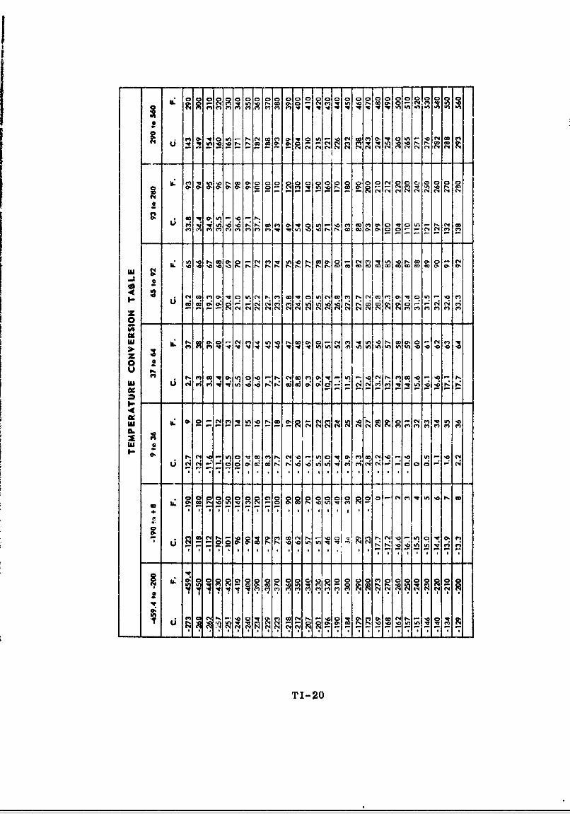
TEMPERATURE
Fahrenheit 5/9 (F-.32) Centt.grade
Centigrade 9/5(C ;1 17.8) Fahrenheit
REFERENCE: Pocket Data for Rocket Engines, by Bell AircraftCorp., Buifalo 5, N. Y.
TI-19
'or o0-0 0 0 F Na a~ gN)i 0 ~ O 0 n
*~*0,vt N ,e u w N w . O o . 'o NC4- Ti--,
co W!vw , , . om10 e L 0mc nQ ,Nc
m - nMI n . Q P oc .0 4
n . ,c ,m- )aN ,0V ýw0 :C
w0 asr . ,F ýw wc cwc
w.C lwv nC P -wcor:C rdd Z @: a- d d- C6 11 C 4v
!! N CC4 C-4 * * C s N C4 N SC m n q4
;;* N M O0
010 0M C (N 14 0 en- q c v
ULN N N ( 4 N r , " C , r
5555 N* * q-nqvwmN iC i
0, ~ ~ T P4I-20i nIVm

;0 0 0 0 0 0 0 0 o 0o 0 0 0 0 0 0 0
I z
ma x
Z- 0
(4 0 - - 6 u 0 Q --J J - -P
0~~ ~ ~ ~ 0 0
w a 4 Aa ma ma aa ma
j 2
tt I02i
2- 0 0
-l 210

~0 0 a 0*
21 1
0, 0 0 0 0 C
00
o-
I - I- e zI
I4TI-22

SOLID PROPELLANT JATO NOMENCLATURE(JATO - Jet Assisted Take-Off)
A JATO unit is defined as an auxiliary rocket that can beattached to a vehicle for the purpose of applying thrust whenneeded. It is further defined as a complete, self-containedrocket unit that has a definite burning time and a fixed thrust.The word JATO has been adopted as the basic term for jet thrustunits and includes boosters, sustainers and aircraft assisttake-off devices.
The complete JATO nomenclature consists of the following
three (3) parts:
1. Basic Name
The basic name is Jet Assisted Take-.Off and isabbreviated JATO.
2. Description
The description is composed of the following:
a. Numerals denoting thrust duration in seconds(at 70 0 F)
b. Two (2) letter symbols denoting the typeand physical state of the propellant. Thistwo letter symbol must be followed by adash (-)
The ±etter symbols for the type of propellant are
as follows:
SYMBOL TYPE
A Acid with fuel or asphalt with per-chlorate
B Ball or chopped double-base
C Composite (picrate-nitrate)
D Cast double-base
E Extruded double-base
F Furfuryl alcohol with oxidizer (in-cludes all alcohols higher than ethyl)
H Hydride fuels
K Cast perchlorates (binder fuels otherthan asphalt)
TI-23

SYMBOL TYPE
N Nitrates and nitro-compounds (otherthan those designated above)
0 Liquid oxygen with alcohol or otherhydrocarbons
SYMBOL PHYSICAL STATE
L Liquids
P Plastic compositions
S Solids
c. Numerals denoting the approximate thrust in poundsproduced by the unit (at 70 0 F).
3. Identification
The identification consists of various symbols andnumerals used to define the status, model and designsequence of the JATO unit.
Minor variations exist in the identifications used bythe Air Force, Army and Navy.
a. Air Force and Army JATOS
The Air Force and Army service standard JATOunits are designated with the letter M andsubsequent standard modifications are desig-nated with the letter A. Frequently standardunits are experimentally modified and desig-nated by M E. Experimental units are desig-nated witE i T and subsequent experimentalmodifications-are designated with the letter E.
b. Navy JATOS
Navy service standard JATO units are debig-nated according to purpose and by the lettersMk. Subsequent standard modifications ared•esignated by Mod. Experimental units aredesignated witT-in X followed by a three (3)digit number. The three (3) digit numbersare the 100 series reserved for JATOS manu-factured by the Aerojet-General Corp.; 20Useries for the Allegany Ballistics; and 300series for NOTS (Naval Ordnance Test Station).Major modifications of JATO units are desig-nated by a letter of the alphabet and subse-quent minor modifications are designated bya number.
TI-24
Examples
1. 2.3 DS-62000 JATO Unit M3El
This is the complete nomenclature for an Air Forceor Army JATO unit.
The JATO unit would be a 2.3 second thrust duration(at 7u0 F), cast double-base (D), solid propellants(S) unit of 62,000 pounds thrust. Its identifica-tion M3El means that it is an Air Force or ArmyJATO experimental standard service unit (designat-ed by M3) and the experimental unit modified onetime (El).
2. 18 ,(S-50000 Missile Booster Mk6 Mod 1
This is the complete nomenclature for a Navy servicestandard JATO (MA6), missile booster, having one (1)modification (Mod 1). The cast perchlorate (K),solid propellant (S) would have a thrust duration ofeighteen (18) seconds and a thrust of 50,000 pounds.
TI-25

MANUFACTURING
JATO, SQUIBS, DESTRUCTORS, zPRIMERS, ROCKET MOTORS, 0
EXPLOSIVE BOLTS
w0
FRECORD 03 RECORD I
CONSISTS OF: U.ORIENTATION Z
CLASSIFICATIONPERSONNEL PROTECTION
STORAGE wMAGAZINE Z
OR IGLOO w
GENERALINFORMATION
TESTING G INSPECTIONBY MISSILE CONTRACTORII G RANGE CONTRACTOR
PERSONNELEQUIPMENT
INTO PAD
MISSILE
• IEPIE 4kIk:UtK IM" WOlr.. AKaW AW4•'k
0 u I O| 0 M I $ $ I 5 A A N G 1 A I v U 5 1 0 mPATRICK AIR FOICI GAIIOL0219&

REVISION SHEET
1. Basic Communication February 1960
Rev. 1-1

Section IGENERAL INFORMATION
I. CLASSIFICATION OF MILITARY EXPWSIVES AND AMMUNITION
Explosives and ammunition ma) be classified according tothe following characteristics:
A. Type
1. Small-Arms Ammunition
Small-arms ammunition consists of cartridgesused in rifles, carbines, revolvers, pistols,submachine guns, machine guns and shells usedin shotguns.
2. Grenades
Gren:.des are explosive or chemical-filled pro-jectiles. They are desigLed to be thrown byhand or projected from a rifle.
3. Artillery and Cannon Powder Ammunition
Artillery and cannon powder ammunition consistsof cartridges, shot and shells that are filledwith high explosives, chemicals or other activeagents and projectiles that are used in guns,howitzers, mortars and recoiless rifles.
4. Bombs
Bombs are containers filled with explosives,chemicals or other active agents designed forrelease from aircraft.
5. Pyrotechnics
Pyrotechnics consist of containers filled withlow explosive compositions. They are designedto be released from aircraft or projected fromthe ground. They are used for illumination,signals and photoflash bombs.
6. Rockets
Rockets are propellant-type motors fitted withrocket heads containing high explosives orchemical agents. Rocket motors in the researchand development phase do not include an explosivewarhead.
1-1

7. JATOS
JATOS are auxiliary rockets that. can be attachedto a vehicle for the purpose of applying thrustwhen needed. They are further describea as com-plete, self-conta.ned rocket units that have adefinite burning time and a fixed thrust. Theword JATO has been adopted as the basic term forjet thrust units and includes boosters, sus-tainers and aircraft assist take-off devices.
8. Land Mines
Land mines are containers, metal or plastic,that contain high explosive or chemical ;gents.They are designed to be laid in or on theground and are initiated by, and directedagainst, enemy vehicles or personnel.
9. Guided Missiles
Tactical guided missiles consist of propellant-type motors fitted with warheads containing highexplosives or other active agents and equippedwith electronic guidance devices. Guided mis-siles in various stages of research and develop-ment do not contain explosive warheads but usehigh explosives in ignition and safety-destructunits only.
10. Dmolition Materials
Demolition materials consist of explosives andexplosive devices designed for use in demolitionand for blasting in military construction.
11. Cartridge-Actuated Devices
Cartridge-actuated devices are devices designedto facilitate the emergency escape of person-nel from high-speed aircraft.
B. Chemical Composition
1. Inorganic Compounds
Examples of inorganic zompounds are:
a. Lead azide
b. Ammonium nitrate.
2. Organic Compounds
Examples of organic compounds are:
1-2
a. Nitric esters, e.g. nitroglycerin and nitro-cellulose
b. Nitro-compounds, e.g. TV'IT und piczic ac"
d. Nitr: .. j-compounds, e.g. tetracene
e. Metallic derivatives, e.g. merr ry iulminate
and lead styphnate.
3. Mixtures of Fuels and Oxidizers
Mixtures of fuels and oxidizerF are non-explosives when used separately but become ex-plosives when combined. Black powder and pyro-technic compositions are examples of this class.
C. Function
1. Low Explosives That Undergo Auto-Combustion
Examples of this class are black powder, pyro-technic compositions and colloided nitrocellulose.
2. High Explosives That Undrrgo Detonation
Examplea of this class are as follows:
a. Inttiatig agents that can be detonated bysp~rk, friction or impact and can initiatethe detonation of relatively insensitive,-plosives. Examples are lead azide andmercury fulminate.
b. Non-initiating explosives that munt be deto-uated by an initiating agent. These are des-cribed as follows:
(1) Booster explosives
Examples of booster oxplosives are tetryland "'TN which are easily ýnitiated anddetonate at high rates. These explosivesare not suitable for loading in masscharges.
(2) Bursting charge explosives
Examples of this group include TNT andExplo3ive D. These exploa-ves areusuafly initiated by means of a boosterexplosive. They can be loaded in masscharges.
1-;

(3) Explosives that are either too sensitiveor too insensitive to be use---alone.Theseexplosives can only be used as in-gredients of mixtures. An example of thetoo sensitive type is nitroglycerin. Anexample of the too insensitive type isammonium nitrate.
By utilizing the special characteristics of theexplosives in these classes, it is practical toestablish the "explosive train." An example of anexplosive train is the initiation of a priming compo-sition by electrical or mechanical means which, inturn, detonates a charge of lead azide. This initiatesthe detonation of a booster charge of tetryl which, inturn, effects the detonation of a surrounding burstingcharge of TNT.
D. Storage
Explosives and ammunition are classified for storagepurposes into quantity-distance classes 1 to 12 inclusive(see "Air Force and Army Quantity-Distance Classificationof Explosives and Ammunition," pages 1-6 thru 1-25 andTable 1-1, "General Classification of Explosives and Ammu-nition with Fire Symbols Included," pages 1-26 thru 1-32).
E. Storage Compatibility
Explosives and ammunition are classified for storageinto seventeen (17) groups which are lettered A thruQ (see "Air Force and Army Group Summary of StorageCompatibility for Explosives and Ammunition," pages1-33 thru 1-40). These groups should not be confusedwith the hazard classification established for quantity-distance requirements. Where two (2) or more quantity-distance classes of explosives and ammunition are storedtogether in a magazine, the quantity-distance require-ments will apply for the most hazardous material storedtherein.
F. Interstate Commerce Commission Shipping Regulations
Explosives and ammunition are classified by FreightTariff No. 9, which publishes ICC shipping regulations,into Class A, Class B and Class C explosives (see Table1-2, "Loading and Storage Chart of Explosives and OtherDangerous Articles," pages 1-41 thru 1-43).
G. Burning or Explosive Characteristics
Explosives and ammunition are classified into four(4) groups according to their general burning or ex-plosive characteristics. These groups are identified
1-4
by "symbols," which are the Arabic numerals 1, 2,3 and 4. Each group consists of one or morespecific quantity-distance classes (see pages 1-83thru 1-86, "Description of Fire-Hazard Symbols" inthe subsection entitled "Storage of Explosives andAmmunition").
H. Security
In accordance with Security Regulations explosivesand ammunition are classified as follows:
1. Unclassified
2. Confidential
3. Secret
4. Top Secret.
1-5
AIR FORCE AND ARMY QUANTITY-DISTANCE
CLASSIFICATION OF
EXPLOSIVES AND AMMUNITION
(Classes 1 through 12 applicableQuantity-Distance Tables)
1-6

AIR FORCE AND ARMY QUANTITY-DISTANCE CLASSIFICATION OF
EXPLOSIVES AND AMMUNITION
Class 1 Quantity-Distance Items
The items in this class are primarily fire hazards and noquantity-distances are assessed for storage. The followingitems are included in class 1:
1. Aluminum powder (packed and stored in originalshipping containers or equivalent).
2. Ammunition, caliber 20-mm or less, except HE, HE-Iand 20-mm incendiary rounds.
3. Cartridge-actuated devices.
4. Charge, spotting, A. P., practice, M8.
5. Chlorates (packed and stored in original shippingcontainers or equivalent).
6. Corporal, actuator, assembly propellant valve,quick release.
7. Cutter, reefing line.
8. Firing devices.
9. Fuse lighters.
10. Fuse, safety.
11. Ignition cartridges for mortar ammunition.
12. Magnesium powder (packed and stored in originalshipping containers or equivalent).
13. Nitrates (inorganic, packed and stored in originalshipping containers or equivalent).
14. Perchlorates (packed and stored in original shippingcontainers or equivalent).
15. Peroxides (except high strength hydrogen peroxide),packed and stored in original shipping containersor equivalent.
16. Squibs, commercial.
1-7

17. Thermite.
18. Zirconium (size of particles 20 mesh, U. S. standardsieve, or greater) packed and stored in originalshipping containers or equivalent.
Class 2 Quantity-Distance Items
These materials may become unsafe under extreme conditions ofmoisture, high temperature or age. They burn with intenseheat but usually do not form dangerous projectiles or generatepressures which will cruse serious structural damage to adja-cent magazines. Table 1 shows quantity-distance relationshipsof class 2 items, which consist of the following:
1. Chemical ammunition, groups C and D when not
assembled with explosive components.
2. Ball, cellulose, nitrate, powder-filled.
3. Grenade, illuminating.
4. Military pyrotechnics (exclusive of classes 4 and 9items).
a. Flares.
b. Illuminants.
c. Incendiary ammunition including projectiles,bombs, grenades and exclusive of N.E-I rounds.
d. Igniters and tracer units (for ammunition).
e. Signals including signal lights, smoke signalsand obscuring smoke.
NOTE: When the items listed in "a" through"e" above are packed and ready forshipment, they may be stored at one-half (1/2) the applicable class 2quantity-distance requirements.
5. Projectiles, illuminating, when not assembled withexplosive components.
6. Propellant, solid. Single-base, multiperforated,having a web thickness greater than U.011 inch.
1-8
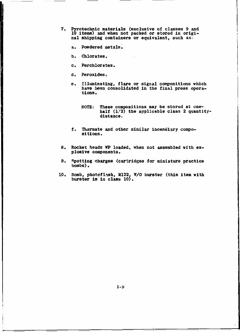
7. Pyrotechnic materials (exclusive of classes 9 and10 items) and when not packed or stored in origi-nal shipping containers or equivalent, such as:
a. Powdered metals.
b. Chlorates.
c. Perchlorates.
d. Peroxides,
e. !lluminating, flare or signal compositions whichhave been consolidated in the final press opera-tions.
NOTE: These compositions may be stored at one-half (1/2) the applicable class 2 quantity-distance.
f. Tharmate and other similar incendiary compo-sitions.
8. Rocket heads WP loaded, when not assembled with ex-plosive components.
9. Spotting charges (cartridges for miniature practicebombs).
10. Bomb, photoflash, M122 W/O burster (this item withburster is in class 105.
1-9
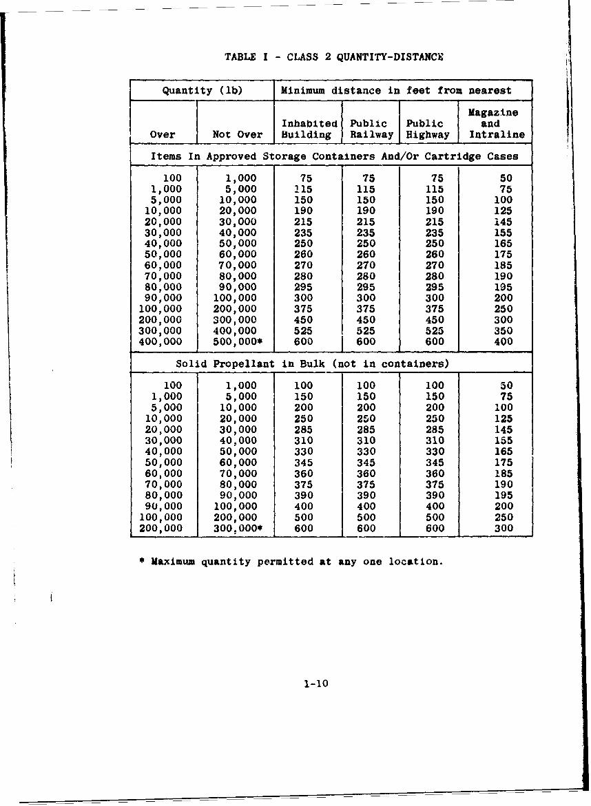
TABLE I - CLASS 2 QUANTITY-DISTANCE
Quantity (lb) Minimum distance in feet from nearest
MagazineInhabited Public Public and
Over Not Over Building Railway Highway Intraline
Items In Approved Storage Containers And/Or Cartridge Cases
100 1,000 75 75 75 501,000 5,000 115 115 115 755,000 10,000 150 150 150 100
10,000 20,000 190 190 190 12520,000 30,000 215 215 215 14530,000 40,000 235 235 235 15540,000 50,000 250 250 250 16550,000 60,000 260 260 260 17560,000 70,000 270 270 270 18570,000 80,000 280 280 280 19080,000 90,000 295 295 295 19590,000 100,000 300 300 300 200
100,000 200,000 375 375 375 250200,000 300,000 450 450 450 300300,000 400,000 525 525 525 350400,000 500,000* 600 600 600 400
Solid Propellant in Bulk (not in containers)
100 1,000 100 100 100 501,000 5,000 150 150 150 755,000 10,000 200 200 200 100
10,000 20,000 250 250 250 12520,000 30,000 285 285 285 14530,000 40,000 310 310 310 15540,000 50,000 330 330 330 16550,000 60,000 345 345 345 17560,000 70,000 360 360 360 18570,000 80,000 375 375 375 19080,000 90,000 390 390 390 19590,000 100,000 400 400 400 200
100,000 200,000 500 500 500 250200,000 300,000* 600 600 600 300
* Maximum quantity permitted at any one location.
1-10
Class 2A Quantity-Distance Items
These materials are similar to class 2 except that they arepotential explosion hazards whereas class 2 items are onlypotential fire hazards under ordinary conditions. The pro-pellants listed are considered class 2A when stored in metal-lined wooden boxes; class 9 when stored in all-metal boxes.Table II shows quantity-distance relationships of class 2Aitems, which consist of the following:
1. Any double-base propellants containing not morethan twenty (20) per cent nitroglycerin and havinga web thickness of 0.0075 inch or greater.
2. Multiperforated cannon and rifle propellant havinga web thickness of not greater than 0.019 inch.
3. Single-base (FNH and NH compositions), single per-forated cannon propellant, having a web thicknessnot greater than 0.035 inch.
4. Single-base, single perforated rifle propellant.
5. Single-base pistol, shotgun and similar low pressurepropellants.
6. M15 and M17 nitroguanadine propellants.
1-11

TABLE II - CLASS 2A QUANTITY-DISTANCE
Quantity Unbarricaded distance in feetof explosive from nearest
MagazinePounds Pounds Inhabited Public Public (intraline(over) (not over) Building Highway Railway distance)
50 250 50 50 50 35250 500 75 75 75 50500 2,500 115 115 115 75
2,500 5,000 150 150 150 1005,000 10,000 190 190 190 125
10,000 15,000 215 215 115 14515,000 20,000 235 235 235 15520,000 25,000 250 250 250 16525,000 30,000 260 260 260 17530,000 35,000 270 270 270 18535,000 40,000 280 280 280 19040,000 45,000 295 295 295 19545,000 50,000 300 300 300 20050,000 100,000 375 375 375 250
100,000 150,000 450 450 450 300150,000 200,000 525 525 525 350200,000 250,0001 600 600 600 400250,000 300,000 675 675 675 450300,000 350,000 750 750 750 500350,000 400,000 825 825 825 550400,000 450,000 900 900 900 600450,000 500,0002 975 1 975 975 650
1. Maximum quantity permitted in a single aboveground maga-zine or operating building. Distances in columns 3 through6 apply to unbarricaded magazines. If the magazine3 or op-erating buildings are barricaded, the quantity of powder maybe limited in accordance with the unbarricaded class 2 dis-tances but the maximum quantity shall not exceed 250,000pounds, except as provided in paragraph 19a of T.O. I1A-1-37.
Distances in column 6 are applicable between all operatingbuildings and/or service magazines in a single line or areawithin the plant boundary and are applicable between maga-zines in storage areas.
Distances shown in column 3 are applicable between separateoperating lines or areas except as provided in paragraph 21fof T.O. 11A-1-37.
2. Maximum quantity permitted in an igloo or corbetta-typemagazine.
1-12
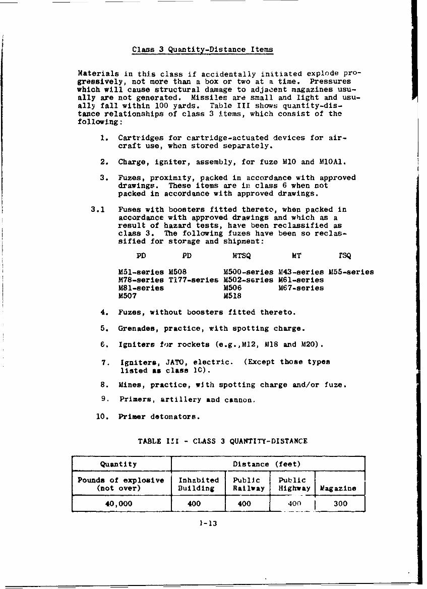
Class 3 Quantity-Distance Items
Materials in thi.s class if accidentally initiated explode pro-gressively, not more than a box or two at a time. Pressureswhich will cause structural damage to adjacent magazines usu-ally are not generated. Missiles are small and light and usu-ally fall within 100 yards. Table III shows quantity-dis-tance relationships of class 3 items, which consist of thefollowing:
1. Cartridges for cartridge-actuated devices for air-
craft use, when stored separately.
2. Charge, igniter, assembly, for fuze MlO and MlOAl.
3. Fuzes, proximity, packed in accordance with approveddrawings. These items are in class 6 when notpacked in accordance with approved drawings.
3.1 Fuses with boosters fitted thereto, when packed inaccordance with approved drawings and which as aresult of hazard tests, have been reclassified asclass 3. The following fuzes have been so reclas-sified for storage and shipment:
PD PD MTSQ MT rsQ
M51-series M508 MSOO-series M43-series M55-seriesM78-series T177-series M502-s6ries M61-seriesM81-series M506 M67-seriesM507 M518
4. Fuzes, without boosters fitted thereto.
5. Grenades, practice, with spotting charge.
6. Igniters for rockets (e.g.,M12, M18 and M20).
7. Igniters, JATIO, electric. (Except those typeslisted as class 10).
8. Mines, practice, with spotting charge and/or fuze.
9. Primers, artillery and cannon.
10. Primer detonators.
TABLE I!I - CLASS 3 QUANTITY-DISTANCE
Quantity Distance (feet)
Pounds of explosive Inhabited Public Public
(not over) Building Railway Highway Magazine
40,000 400 400 400 300
1-13

Class 4 Quantity-Distance Items
Materials in this class usually explode progressively,.a fewboxes at a time, when accidentally initiated. Many explosionsof individual rounds would be of low order. Items in thisclass must be packed in accordance with approved ordnancedrawings and specifications. Table IV shows quantity-distancerelationships of class 4 items, which consist of the follow-ing:
1. Ammunition, blank and saluting, cannon.
2. Ammunition, caliber 20-mm or less HE and HE-I and20-mm incendiary rounds.
3. Ammunition, fixed and semifixed, inert projectilesand those loaded with Ammonal, Amatol, CompositionB, Explosive D, TNT or Baratol.
4. Bombs, chemical loaded, with explosive burster.
5. Chemical ammunition, of groups A, B, C and D, fixedand semifixed or separate-loading chemical filleditems assembled with explosive bursters.
6. Mines, antipersonnel (bounding type).
7. Rocket, chemical, complete round.
8. Rocket, practice--inert head.
9. Rocket motors (exclusive of heads).
10. Shell, illuminating, complete round.
11. Shell, light mortar, 81-mm and less (excluding 81-mmM56).
NOTE: When items in this class (except chemical)are not packed in accordance with approvedordnance drawings, the Class 10 Quantity-Distance Table will be used to compute dis-tances.
TABLE IV - CLASS 4 QUANTITY-DISTANCE
Quantity Distance (feet)
Pounds of explosive Inhabited Public Public(not over) Building Railway Highway Magazine
500,000 1,200 1,200 1,200 300
1-14

Class 5 Quantity-Distance Items
Materials in this class if accidentally initiated usuallyexplode one shell at a time, and in nearly all cases, withlow order, The projectiles are limited as to number andrange and most of them fall within 400 yards. Items in-cluded in class 5 consist of separate-loading shells loadedwith Explosive D and any other Explosive D loaded shell notassembled to or packed with cartaridge cases. Table V showsquantity-distance relationships of class 5 items.
TABLE V - CLASS 5 QUANTITY-DISTANCE
Quantity !Distance (feet)
Pounds of explosive Inhabited Public Public(not over) Building Railway Highway Magazine
650p000 19200 1,200 .t200 300
1-15

Class 6 Quantity-Distance Items
Materials in this class If accidentally initiated usuallyexplode progressively by stacks Missiles are light andusually fall within 200 yards. Table VI shows quantity-dis-tance relationship of class 6 items which consist of thefollowing :
1. Adapter--boosters,
2. Boosters.
3. Fuzes, chemically actuated, containing ampouleswhich may initiate, directly or indirectly, explo-sives and explosive loaded components which are as-sembled in the conventional manner to form thefinished explosive fuzee
4. Fuzes, proximity, not packed in accordance with ap-proved drawings. When these items are packed inaccordance with approved drawings they are consid-ered in class 3.
5. Fuzes, with boosters assembled thereto. For ex-ceptions, see item 3.1 of Quantity-Distarce Class 3.
6. Mines, APERS, NM, N14, with integral fuze.
NOTE: See paragraph 21c(3) of T.ki. IIA-1-37 forspecial requirements in the st, rage of itemsin class 6.
TABLE 'VI - CLASS 6 QUANTITY-DISTANCE
Quantity Distance (feet)
Pounds of explosive Inhabited Public Public(not over) B,'ilding R/- lvaa Highway Magazine100,000 I, 00 900 450 300
1-16
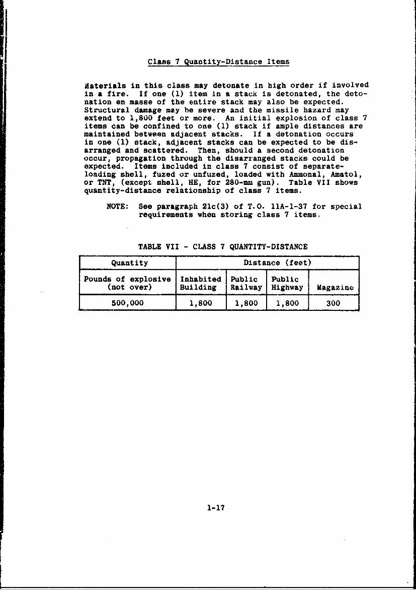
Class 7 Quantity-Distance Items
Materials in this class may detonate in high order if involvedin a fire. If one (1) item in a stack is detonated, the deto-nation en masse of the entire stack may also be expected.Structural damage may be severe and the missile hazard mayextend to 1,800 feet or more. An initial explosion of class 7items can be confined to one (0) stack if ample distances aremaintained between adjacent stacks. If a detonation occursin one (1) stack, adjacent stacks can be expected to be dis-arranged and scattered. Then, should a second detonationoccur, propagation through the disarranged stacks could beexpected. Items included in class 7 consist of separate-loading shell, fuzed or unfuzed, loaded with Ammonal, Amatol,or TNT, (except shell, HE, for 280-urn gun). Table VII showsquantity-distance relationship of class 7 items.
NOTE: See paragraph 21c(3) of T.O. 11A-1-37 for specialrequirements when storing class 7 items.
TABLE VII - CLASS 7 QUANTITY-DISTANCE
Quantity Distance (feet)
Pounds of explosive Inhabited Public Public(not over) Building Railway Highway Magazine
500,000 1,800 1,800 1,800 300
1-17

Class 8 Quantity-Distance Items
Materials in this class are expected to detonate en masse ifinvclved in a fire. Principal damage is usually due to blastor shock effect as the missiles are light and limited inrange. Table VIII shows quantity-distance relationships ofclass 8 items, which consist of the following items whenpacked in accordance with approved ordnance drawings andspecifications:
1. Blasting caps.
2. Detonators.
3. Percussion elements.
4. Primers, electric.
TABLE VIII - CLASS 8 QUANTITY-DISTANCE
Quantity of explosives Unbarricaded distance in feet*
Inhabited Public PublicPounds Pounds Building Railway Highway Magazine(over) (not over) Distance Distance Distance Distance
500 1,000 720 430 220 1801,000 1,500 860 520 260 2001,500 2,000 980 590 300 3002,000 5,000 1,200 720 360 3005,000 10,000 1,500 900 450 30010,000 15,000 1,610 970 490 30015,000 20,000 1,740 1,040 520 300
* These distances may be halved when requirements of paragraph18 of T.O. 11A-1-37 are complied with.
NOTE: For quantities less than 500 pounds of explo-sives, the class 10 table distance shall beapplied.
1-18
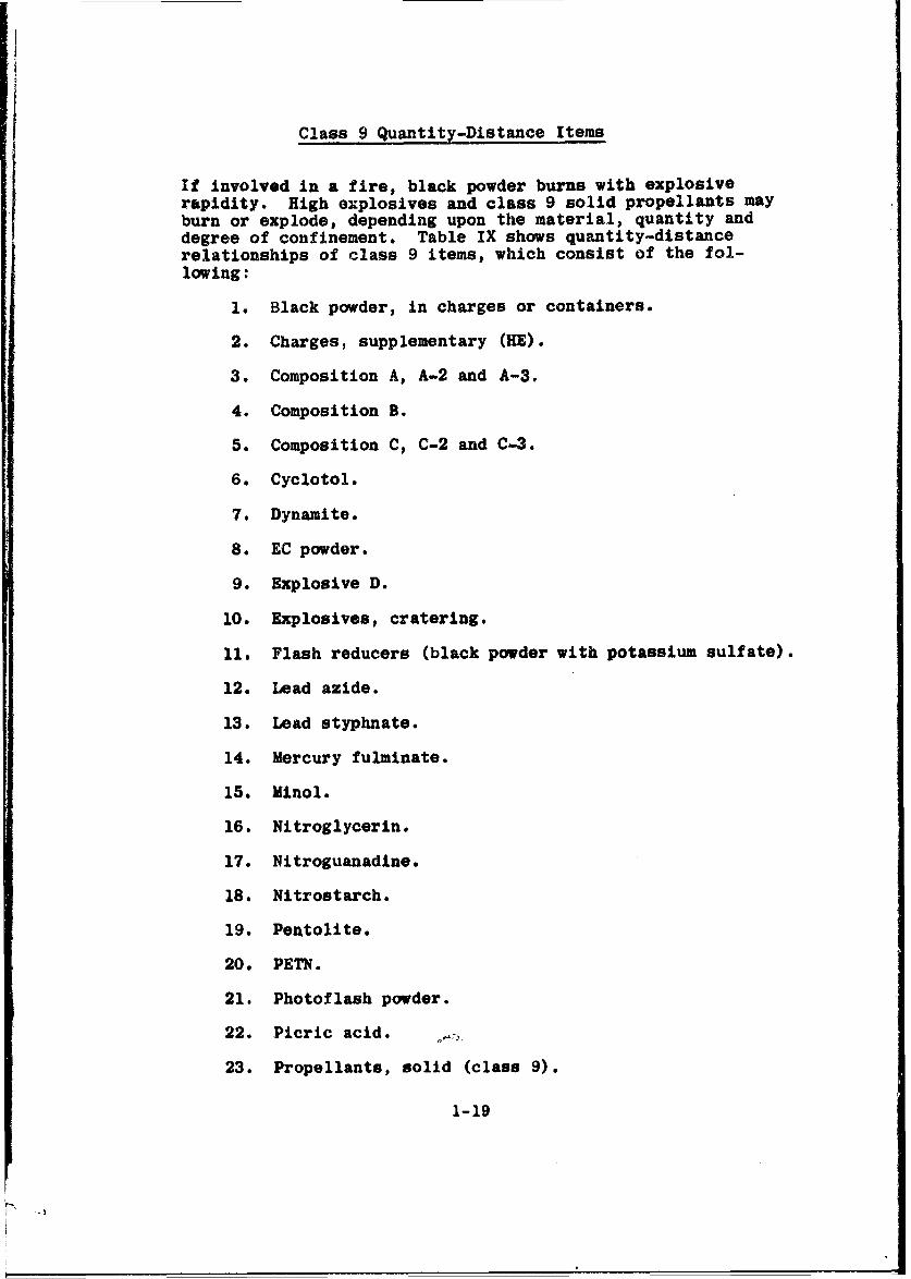
Class 9 Quantity-Distance Items
If involved in a fire, black powder burns with explosiverapidity. High explosives and class 9 solid propellants mayburn or explode, depending upon the material, quantity anddegree of confinement. Table IX shows quantity-distancerelationships of class 9 items, which consist of the fol-lowing:
1. Black powder, in charges or containers.
2. Charges, supplementary (HE).
3. Composition A, A-2 and A-3.
4. Composition B.
5. Composition C, C-2 and C-3.
6. Cyclotol.
7. Dynamite.
8. EC powder.
9. Explosive D.
10. Explosives, cratering.
11. Flash reducers (black powder with potassium sulfate).
12. Lead azide.
13. Lead styphnate.
14. Mercury fulminate.
15. Minol.
16. Nitroglycerin.
17. Nitroguanadine.
18. Nitrostarch.
19. Pentolite.
20. PETN.
21. Photoflash powder.
22. Picric acid.
23. Propellants, solid (class 9).
1-19
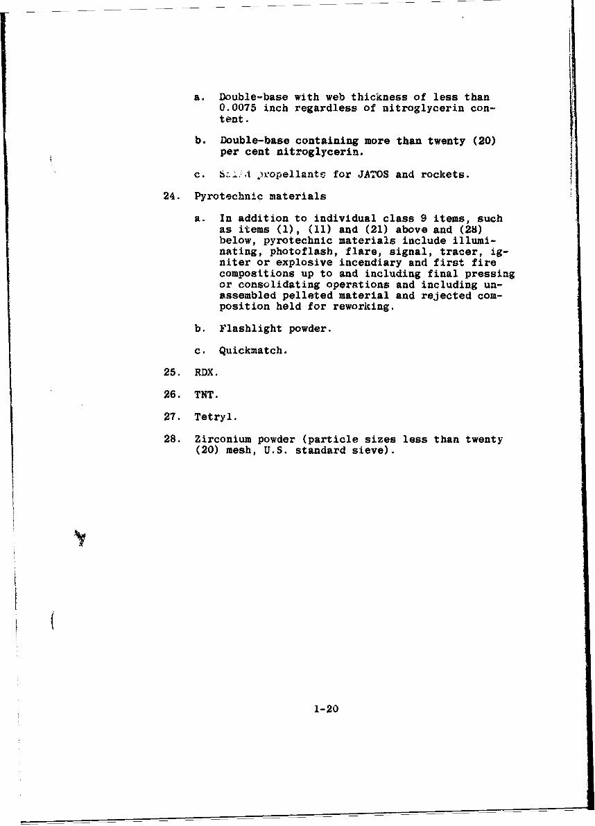
a. Double-base with web thickness of less than0.0075 inch regardless of nitroglycerin con-tent.
b. Double-base containing more than twenty (20)per cent nitroglycerin.
c. _) ,ropellantv for JATOS and rockets.
24. Pyrotechnic materials
a. In addition to individual class 9 items, suchas items (1), (11) and (21) above and (28)below, pyrotechnic materials include illumi-nating, photoflash, flare, signal, tracer, ig-niter or explosive incendiary and first firecompositions up to and including final pressingor consolidating operations and including un-assembled pelleted material and rejected com-position held for reworking.
b. Flashlight powder.
c. Quickmatch.
25. RDX.
26. TNT.
27. Tetryl.
28. Zirconium powder (particle sizes less than twenty(20) mesh, U.S. standard sieve).
1-20

Class 10 quantity-Distance Items
If involved in a fire, class 10 ammunition may be expected todetonate in high order and all the ammunition in one (1) maga-zine may detonate en masse simultaneously. Table IX showsquantity-distance relationships of class 10 items, which con-sist of the following:
1. Ammunition, fixed and semifixed, loaded with highexplosives other than Ammonal, Amatol, CompositionB, Explosive D, TNT or Baratol.
2. Ammunition, separate loading, loaded with high ex-plosives other than Ammonal, Amatol, TNT, ExplosiveD or Baratol.
3. Bangalore torpedoes.
4. Bombs, demolition.
5. Bombs, fragmentation. Class 10 distances are ob-served, however, no distance shall be less thanthat required for class 4 ammunition.
6. Bombs, photoflash, w/burster (bomb, photoflash, M122,
w/o burster, is in class 2).
7. Boosters, auxiliary.
8. Bursters.
9. Cartridge, photoflash.
10. Charge, springing, earth rod, blast driven.
11. Demolition blocks.
12. Demolition charges, snake.
13. Destructor, HE, MIO.
14. Firecracker, M80.
15. Grenades, fragmentation.
16. Grenades, hand offensive.
17. Grenades, rifle, AT.
18. Igniters, JATO, electric (such as M29).
19. JATOS, complete rounds.
20. Mines, antipersonnel (cast iron block).
1-21
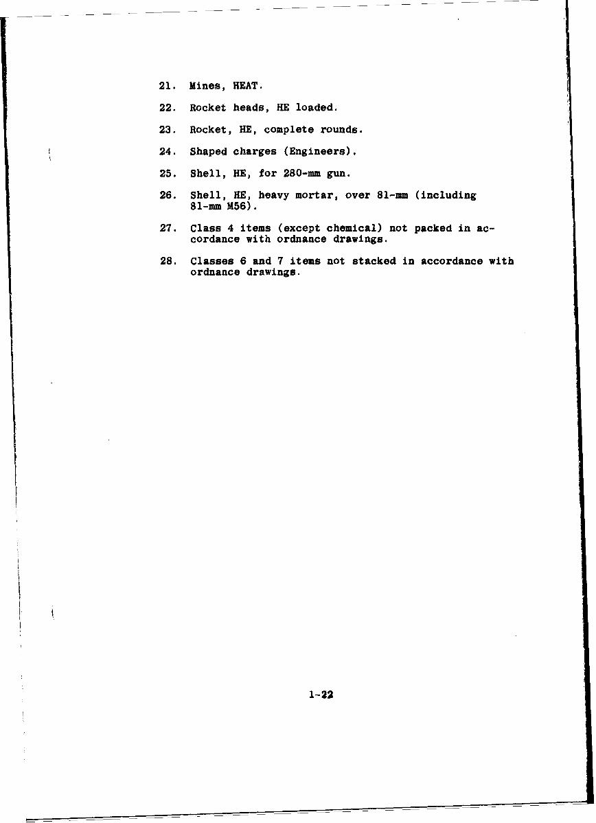
221. Mines, HEAT.
22. Rocket heads, HE loaded.
23. Rocket, HE, complete rounds.
24. Shaped charges (Engineers).
25. Shell, HE, for 280-mm gun.
26. Shell, HE, heavy mortar, over 81-.mm (including81-mm M56).
27. Class 4 items (except chemical) not packed in ac-cordance with ordnance drawings.
28. Classes 6 and 7 items not stacked in accordance withordnance drawings.
1-22

r-4 I 00 00 0 00 00000 00 0 0 0qm w-m-m m N (OOc
44.
V' 00812 2
r-r4 0 P.r4~44"~r4 cit oI at t0w ma -Cq m v CUlC'
A9 W14 ra ~ ~ iO
43 v0 tot ) 0 0 8 0 0
A v rr~r~cmv) tt- 00CDCA 80 H U S) W o t- - t- V-4 4q v LOe
- -q
0
V4
0 00k C
1-23
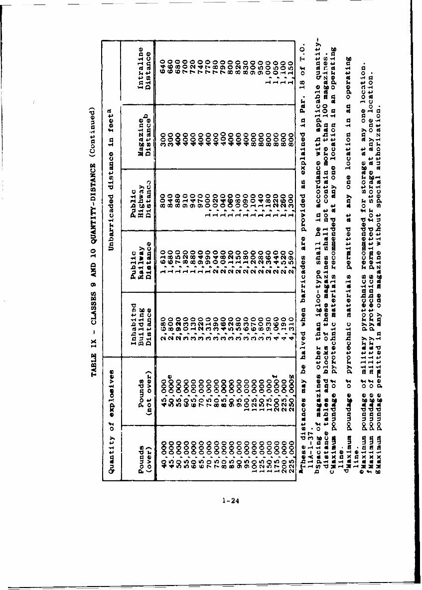
0 0 4J
E"4~~~Fw ~0 0 0 0 0 0 0 0 04J -4914j4~
14 4J 0 W - - 0 k'5 44 0r- r- 0-4r 0A k 4 J 09
.aa 0 0 t__ _ 4 uC
-u 0. 0900 ' 0. Cd 00-4
V 0 0 0~oaa4-)
a a 'U4) 0 0~0 0 0 .a .'. 0 '4)"4) a( 4) A 9 440d to 00 C
00 ~ ~ 1 .O 00 OD0 043 4
"4 44 54*' 0J '4-1 (da a )Iko '
0 ~-.~' 01"4Ut'-C~W~a~~CI r0 00 a J 54J0 .050o""44~q~~ 4 04 46 0.9.4.9.4 P.4a a .cd41
.(A 4. 0419go a a4 M 0a 0
"4~~~-40 000J 13~t~ 009" ~ ~ ~ 0 U00 0 S4)M.0 4 * 0 a 0 a- V t- 0 N (n 54 V. 50"04 0 of
1. U C3 4) 4jU~4 0.W U
r4 4J 4-F-014 V4 .aHa
0000 000 000 000 0 0d 0 09-4 V4bO vwNU 0 0VvN ) a 4 M C
oo o o o oo o o o .a . t.......a 31964. F4 U4 r- - - - i ýC ý a4 '4d0
.0v' 0. Naa(aaODa ago 0 bb
-4 > am r4Q CU Q ccc a00 r4 -44
to 0 4 ~ .1 '44P4 o 0 u0 00. 0
to0 0a 0A 00 0 d +j ~ 4~4- 3Q 40a a 00 .
i-i 0. 0 0-4c~
'4)' 0 r
~~~8 00QOQQ00000 0 0 go4I.I0 0
0 o :0011.0-40.44'&4 U&
0v t 0i
1-240000 9

Class 11 Quantity-Distance Items
No quantity-distance tables are established for class 11items, inasmuch as the items assigned to class 11 are notconsidered explosive hazards. The following items are in-cluded in class 11:
1. Chemical ammunition, groups A and B, when not as-sembled with explosive components.
2. Rocket heads, chemically loaded, except groups Cand D, when not assembled with explosive com-ponents.
Class 12 Quantity-Distance Items
The items included in class 12 are considered relatively in-sensitive and can normally be detonated only by very stronginitiation. The applicable quantity-distance tables to beused in the handling and storage of the items in class 12shall be governed by the actual physical location selectedfor the items with respect to adjacent detonation or firehazard materials. (See requirements listed in par. 21C(3)(c) or T.O. l1A-1-37). The following items are included inclass 12:
1. Ammonium nitrate.
2. DNT.
3. Nitrocellulose, wet, containing from 8 to 30 percent water.
4. Detonating cord.
1-25

TABLE 1-1
GENERAL CLASSIFICATION OF EXPLOSIVES AND AMMUNITION
ITEMS WITH FIRE SYMBOLS INCLUDED
1-26
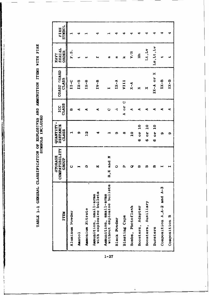
E44
1.4
0 0- x>0.4 0.4 x
C.)
0-44 pa 0 0 04044 4 4
01
0 P-I - -P4 04 $4z
r -4 P4 04 1
43o 4) tvto)
mO 0
* 0 X 4cOP- -4)
04 0 0` 04
I0r4 '-q ~ .1 f 0 M 0-4 4 0 ) 13 I 0 44 4J CCv 4 3 J 4
0~~ 0 0 0P~4
1-27
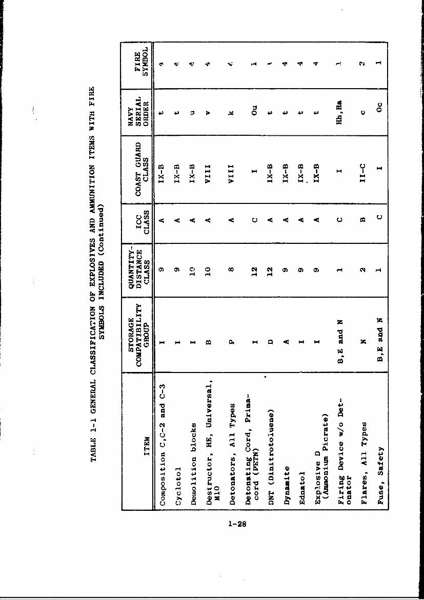
PZ4 94I
p0- 4.' 4J +. 4J.
z (a
z,0-
-~ x x2
00
P4)C
C400Go
C)I > .4 -
ra44 a 4) -
N2 wo24-
rqI A S
0 ;A m 0iF-4 4 0 +a"4 4)
a~c U ,-0)aU~~ k r4 14 0
.r 0 0 $ 4 03 AU 4T41 0 4-) Q 4~0 4J A4 4) F-4 , aC0
.0 k 0 931 0 0 U )f 4 -ý 0 0 2 14 4 4-) k
0 (n 14 4-) M4- 0 . c 4
-) C.) 1 w P4 0 P2 bl 4
1-28

01'
042
~02O
- E-4
U 02
Do2 P4
Go I m
02C
00
P4 E, .0 0
0200
02V 4*4C 0
ol 0' 10r - 1a
d ttP4 40 .4 o 1
*1.a *QO d0 -1a 0.4 4 6 6-4 41 #
w4 41-b4-b M 0 A 01 .0 P. 144. ~0I M 44) v 3 6 +
0 k .4 d* ( 4'4 d 0
ON o 04 -o9 0 N 1 C 4C
1-29
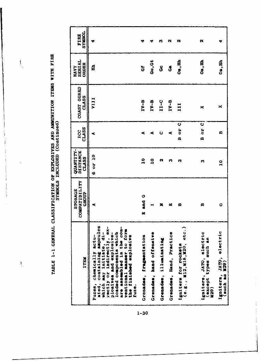
040
0 0 00co
0:54 - ~04 0 i 4 c'
WC 00
011
%4 p -.4 .4 $5 400
r4 V -440 4a
b.4- -,4 4 4. - 40
A 1 4.
0 0 (a * W44 aeq
54~ ~~~ X4 5 - ~ - '
1-30

9u20
0 -
1-
o~~b 0
0v 0
"a 04 Q "4
~e~0
-d
"4 0 00 :04
U. 4 14
0 "4 6. a .4 00
-W4 o P4 V4"x 4zS* N N'
1-31

010'
4J4
14 u
- ~k 0 4 z
ok 44
0 0 p
"-4
U ~as
ra~~ 0*.i
F-4 40 Uý
00
Up
00 P- --
wa *
tU 0 MM Q4U
I 4 1. Sl4' -4 "
1-32

AIR FORCE AND ARMY GROUP SUMMARY
OF STORAGE COMPATIBILITY
FOR EXPLOSIVES AND AMMUNITION
1-33

AIR FORCE AND ARMY GROUP SUMMARY OF STORAGE COMPATIBILITY
FOR EXPLOSIVES AND AMMUNITION'
GROUP A--Separate Storage 2
Ammunition, pentolite loaded [except pentolite-loaded riflegrenades (other than the grenades listed below) and rock-ets].
Chemical ammunition, group A chemical agents.
Chemical ammunition, group B chemical agents.
Chemical ammunition, group C chemical agents.
Chemical ammunition,. group D chemical agents.
Dynamite.
Fuzes, chemically actuated (see exceptions in Table 1-1,"General Classification of Explosives and Ajmunition ItemsWith Fire Symbols Included").
Grenades, rifle, AT, pentolite loaded.
Photoflash powder.
Pyrotechnic materials except items in groups C and K in thisTable (see par. 22a and Tables III and XI.of T.O. 11A-1-37).
Shell, separate, fuzed or unfuzed, all calibers, loaded withExplosive D.
Shell, separate, fuzed or unfuzed, all calibers, loaded withany HE other than Zxplosive D.
Explosives and ammunition are divided Into seventeen (17)storage compatibility groupings based on: (a) the effects ofthe explosion of the item, (b) the rate of deterioration,(c) the sensitivity to initiation, (d) the type of packing,(e) the effects of fire involving the item and (f) the quan-tity of explosive per unit.
2. Items of this group must be stored alone.
1-34

GROUP B 3
Adapter-boosters.
Ammunition, caliber 20-mm or less, except HE and/or HE-Irounds and 20-mm incendiary rounds.
Boosters.
Boosters, auxiliary.
Bursters.
Cartridges, CAD.
Cartridge-actuated devices.
Charge, igniter, assembly, for fuze, M10 and M10A1.
Charge, spotting, AP, practice, 18.
Charges, supplementary.
Corporal, actuator, assembly propellant valve, quick release.
Destructor, HE, M10.
Firing devices.
Fuse lighters.
Fuse, safety.
Fuzes, with booster, except chemically actuated (see Table1-1, for inclusion of certain types of chemically actuatedfuzes),
Fuzes, without booster, except chemically actuated.
Ignition cartridges for mortzr amaunition.
Igniters for rockets (112, M18, M20, etc.).
Igniters (electric) for JATOS (class 3).
Mines, APERS, NM, M14.
Primers, cannon and artillery.
Primer-detonators.
Squibs, commercial.
3 Items in Groups B through Q may be stored with other itemswithin the individual group in any combination.
1-35
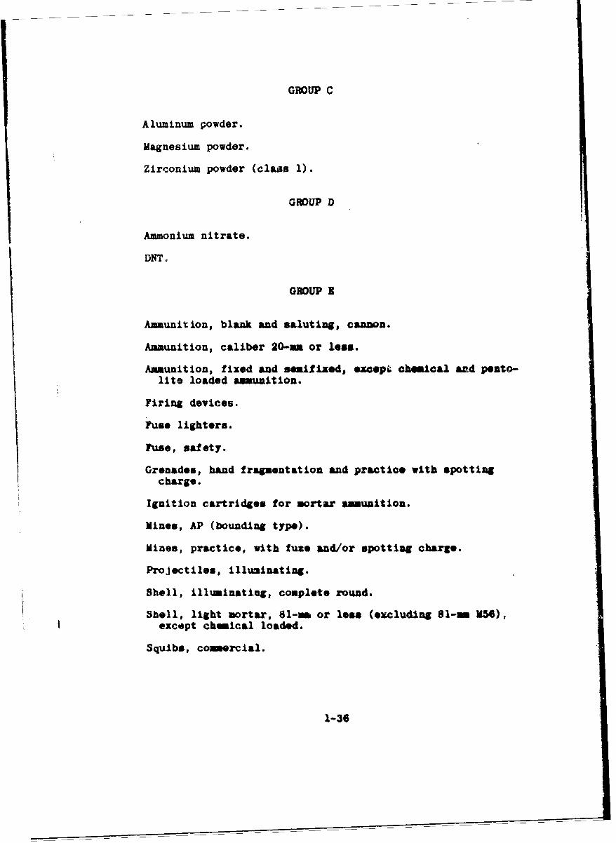
GROUP C
Aluminum powder.
Magnesium powder.
Zirconium powder (class 1).
GROUP D
Ammonium nitrate.
DNT.
GROUP 3
Ammunition, blank and saluting, cannon.
Ammunition, caliber 20-mm or lese.
Ammunition, fixed and snmifixed, =ocep& chemical and pento-lite loaded ammunition.
Firing devices.
Fuse lighters.
Fuse, safety.
Grenades, hand fragmentation and practice with spottingcharge.
Ignition cartridges for mortar ammunition.
Mines, AP (bounding type).
Mines, practice, with fuze and/or spotting charge.
Projectiles, illuminating.
Shell, illuminating, complete round.
Sbell, light mortar, 81-m or less (excluding 81- NN6),except chemical loaded.
Squibs, comnercial.
1-36

GROUP F
JATOS, complete rounds.
Rockets, HE, complete rounds.
Rockets, practice.
Rocket motors*
Rocket heads, HE (without motor).
GROUP 0
Bangalore torpedoes.
Bombs, demolition.
Bombs, fragmentation.
Rocket heads, HE (without motor, except pentolite loaded).
Mines, AP (cast Iron block).
Grenadea, fragmentation.
Grenades, rifle*, AT (macopt pentolite loaded).
Shell, heavy aortar, over 81-rm (including 81-m M56), exceptchemical !oaded.
Snake, detolitiou.
Snake, mine clearing.
GROUP H
Mineso, Eg, AT (to be combined with group G upon completionof replacement of cheaically actuated fuses of the /600type).
GROUP I
CBS (experimental propellant - 85% RX and 15% desensitizer).
Charge, springing, earth rod.
Composition A, A-2 and A-3.
1-37

Composition B.
Composition C, C-2 and C-3.
Cyclotol (not to exceed max. 85 per cent RDX).
Demolition blocks.
Explosives, cratering.
Explosive D.
Grenades, hand offensive.
Minol.
Nitroguanadine.
Nitrostarch.
Pentolite.
Pi-ric acid.
Primacord,
Shaped charges.
TNT.
Supplementary charges.
GROUP J
Charges, propelling.
EC powder in bulk.
Propellants, solid (class 2).
Propellants, solid (class 2A).
Propellants, solid (class S).
GROUP K
Chlorates.
Nitrates (inorganic).
Perchlorates.
1-38

Peroxides, solid.
GROUP L
Cyclolite (RDX).
Tetryl.
GROUP M
Lead azide, wet.
Aead styphnate, wet.
Mercury fulminate, wet.
PETN, wet.
Zirconium powder, wet.
RDX (wet).
Nitrocellulose (wet).
GROUP N
Ammunltion, caliber 20-mm, or less, except HE rud/or HE-Iand 20-mm incendiary rounds.
3.il, cellulose nitrate, powder-filled.
Charge, spotting, AP, practice, M8.
Corporal, actuator, assembly propellant valve, quick release.
Firing devices.
Fuse lighters.
Fuse, safety.
Grenades, illuminating.
Ignition cartridges for mortar ammunition.
Military pyrotechnics except items in this classificationlisted separately in Groups A and M of this Table.
Projectiles, illuminating, without propellant.b
1-39
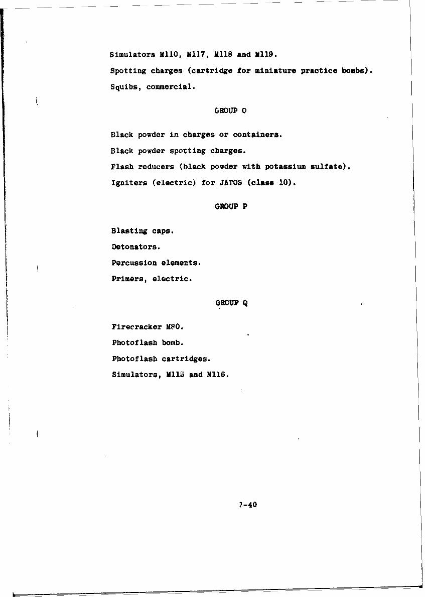
Simulators Ml1O, M117, M118 and N119.
Spotting charges (cartridge for miniature practice bombs).
Squibs, commercial.
GROUP 0
Black powder in charges or containers.
Black powder spotting charges.
Flash reducers (black powder with potassium sulfate).
Igniters (electric) for JATOS (class 10).
GROUP P
Blasting caps.
Detonators.
Percussion elements.
Primers, electric.
GROUP Q
Firecracker M8O.
Photoflash bomb.
Photoflash cartridges.
Simulators, Mll and M116.
2-40

TABLE 1-2
LOADING AND STORAGE CHART OF
EXPLOSIVES
AND OTHER DANGEROUS ARTICLES
1-41

TABLE 1-2 - LOADING AND STORAGE CHART OF EXPLOSIVES
AND OJTHER DANGEROUS ARTICLES*
I.: A
d sA , ý,qtth or a t I!, 7 nct, v. of z 13
Ajiv, dais or b il" . rt i ,a -Ni4 t3. ` ! .1 -' j ;
c~t;~ezl I i.IIIma (ý ILWD
96 1. 94
a b e d II I 1 1 34 A£ to I 1 1i~2 3 14 IS
CLAI4 A 1XPLOCXVZI
Low expl.'ivtp 2,r Unit Pý'der s ........ ... ... ... .... xX . ...... x x x
Hiqh fzvkt'asv"or - - - - - - - - - -
@IV". class A.. ...... . ....... b ... .. X AX ......... .... X ... .... X .. ...... X X a.X XX \
pfitCrg c r rtnttr expI-lirea.
Dat of jiste 'r try suanil, I "I~"-.aM:tl.) Ituan ) yu I- bt ItdAunt,iclid Aside,. lead Ptyphnate natrt,
*rytLrss~t# tetvtwratr. LttrnseC _X ~.X x X x _I x X x x x x x x X X A I .X
llattges *.ti or ith-a -let,
cap-. dvirsrwtme pzn rr d 11 X X .. N IAS Ax Ix XX x1a~gL
Ammunith or attooana withs ij)Ao.Gies Dio~ttllo. xai pMi'ctttc.,*Amoe. illtnalatim. tiarWnda cwo
a~hrl. smflunattt frn alaff arm.,with. vvpI..s~e Itlu-to. 1'r antrou-saiwa for asmP1 art. ,Ish x-
Dv mogri'&.2 *uno-k.f prntr~-
in#__ IM )W4 !aCl-WJ 3"Ie EILSVI .
.1Z.1 ssel,'A t.
;,- -. . -.ý - L1-a

TABLE 1-2 -LOADING AND STORAGE CHART OF EXPLOSIVES
AND OTHER DANGEROUS ARTXCLJES (Continued)
~-&M "R
.rv. and rrdrgr' a. IIWhicha mum, not be loaded or at-,red s a j[ '-
I'r etrXat an wnt~raetoin of.IS AI P 1!!ihoirizrnyal arid ve tical ealrrnmap . .bekamd.d oralr .oe 9.bF.fr ~ ii~ IIi
a V I iiiia
M4nt hoiotlolm 4 9c
Pdn ort lode or st~1 ored ..highy espnaom~i aeil~kpe
dsa1ra.rni Coezt~idcal o.so.
3tims soaty genadr. prJimd
Small aArgu rammuiton psiuoa
der gltayrep. emptyav cerLuto au%pried emtyf v greadve . printed.
Pus.ombnstue. ta-eri, or pruesm a
$0Ms ex=Mbatlo sdsaale 3
cUWA~ki fue.nai tnocis insesto
sTim s. exmbss arido ,tup w IGoitri, II.4ij esdM - ' L ' . - Ix .. . . . . .. . . .. . . .
W oor wyt .. ... ..... . I X ....
OTOU DANOswuUARTICLIU
F misamabiv "qWd or 4axipuii -s
itils YUVb. 1 1 x 431 si X-m
X I I XI ex six a.X
go~~~~~ re k& IIXA
U*4woeevU go."a& (h Wsit
fI x I I
aR~s~ta orep o~swirwr Meet we cape to ~uLwl w~4 asoomia IA as way ohma hr, bedw 6Wd arterieset vo~ise In *el W,~ Ad ousolvnaw 1. 0. IS.111i. tdiril tad~aag mod traemb~mm 41 hisog amoo oa6r olsoq loio Oak msa mpmnoa) l. ase esv masy. .,li Woiwe. "aamad
a Ad r ale,~,sr. aj4~. ~aa ski.saaast WAe be k*4ad*e" ohre adss 1. As~aftoalml Wibo or s46wes Uamrumi T-11. 640 aftmeuvAitp.~ fy wean a
prmwerre tnpam vIb.iaar tSWm ed wImems es i ha2e t.. miliaser of mmblef -u:14a R 4 sm a damewap' -4, ~t.-6.mFE~mie.sam de, A. mad .p adw~3s.. srr W : k"W h.0d ow". w'ath .&amaiosd eamsm~sas m oAW -e~J h.If er w"~ pheubolm,*% witimov vvt
- 's~~oertbwss~~ s~gm. (hm~ t~~m ~8sasi'm ~atlm ~ I ellem7 eb or W" P6a.4.reo may be 0.6 A.4 madew-t.p.4kmsr1-01hft e trpjapWir saapgbams ef Iedi s~Is5 up""v milleyl 6,qmob ohm hAippd bv. a. ai te ll', 0-taatt . Arom,
Navy, and Ast Virm .4 0t. I a,1 w" "tees (osaoe~s,am mmy be $Mdoil e*A &67 ofti~me uvtiwrsaas sMV tomos IQ. -jimaad '0 .IIIi. ra isa DMS. Wr-4 Ifid-1 Wte m ýk- MetIM1,tiaw uas emrftivamlsb 0110161.1 OWPW. elU& 0*7 10s **'. M* Sm Wba 06mmai .h kraA p'biaaa or "Imt bwm* saps
an= ' -W wOr..4. :=*a~~w mie4 "a Ws loaaded .6 time saw vlallr "It vv sahom AData S-pmaae ry~t etanbiteaw smst *-A be lode or stawc WIith an. or "WPM" qWNOW11 rso3 mm dr~tafireL.etm wa @y b. kindad it"i tusvrtomri sttha~ siritves boomed oems the is rAvmsmr
N- A-NQ;amew arM.eha loaded 1. 00 smme gwt valmd Wft isf bo or O evja -- ud sm~e"I beb han led rom 41bm~er esstpa I ~ ~ ~ ~ ~~a "re *a sea "hk dse ber haul it a.mb mkw md~ a au a
1403

l I. GENERAL SAFETY PRECAUTIONS
A. Introduction
Improper handling of explosives and their accesso-ries Ray cause accidents resulting in serious injuriesor death to personnel and the destruction of property.The history of accidents with explosives indicates thatin practically every instance these accidents couldhave been avoided. Therefore, the general safety pre-cautions discussed herein shall be strictly enforced.
B. Personnel Safety
1. Extreme care shall be exercised in the selectionof personnel employed to handle explosives andammunition. Only those physically and mentallycapable of realizing their responsibilities tothemselves and others shall be employed.
2. Explosives and ammunition shall be handled underthe direct supervision of a competent person whounderstands the hazards and risks involved. Per-sonnel handling explosives and ammunition shallbe thoroughly instructed that their safety, aswell as that of others, depends upon the degreeof intelligence and care exercised by them whenhandling explosives.
3. Personnel handling explosives and ammunitionmust not tanper with or disassemble any conpo-nents unless authorized to do so. Seriousaccidents may result.
4. Persons handling explosives &nd ammunition mustclean all mud and grit from their shoes beforeentering the magazine, car, boat or vehiclewhere explosives or amunition are contained.
5. Protective clothing and equipment furnished byPAA shall be utilized as required (see sub-section entitled "Protective Clothing andEquipment," page 1-51). Clothing not worn duringworking bours must be placed in approved lockersin designated locations.
6. Safety shoes of the appropriate type shall beworn where operations require the handling ofexposed explosives. Exposed explosives may beignited by static discharge, friction or impact.
C. Care and Precautions In Handling Explosives and
Ammunition
1. In addition to the explosive hazard, explosives
1-44

also have varying degrees of toxicity hazardwhen inhaled, ingested or absorbed through theskin. Dust-air mixtures also present an addi-tional explosion hazard. Therefore, explosivesmust be hand'ed only when udequate ventilationis provided to preclude the formation of dust-air mixtures. Spark discharges of static elec-tricity shall be prevented by the installationof proper grounding devices.
2. The inhalation of vapors of nitroglycerin or thenitrated glycols can cauce severe headache.Some individuals are sensitJve to very smallquantities of these materials. The inhalationof the dusts or vapors of nitro-compounds suchas TNT and picric acid has been known to havefatal effects on personnel. Explosives, there-fore, must always be handled in adequately ven-tilated areas.
3. The effects caused by the contact of explosiveswith the skin, vary from simple discoloration todermatitis and from headaches to poisoning.These discomforts are caused by absorption ofthe gaseous or liquid materials through the poresof the skin. After handling any quantity ofexplosives, the hands shall be washed thoroughlywith soap and water. Personnel working with ex-plosives throughout the day shall bathe them-selves thoroughly and change clothes upon com-pletion of their duty.
4. The nervous reaction of an individual workingwith explosives is of great concern. The ex-tremely nervous individual and the hurriedworker shall not be permitted to handle explo-sives. Personnel having a calm disposition anda conscientious attitude will probably maintaincloser observance of standard safety regulations.
3. The number of personnel exposed and the quan-tity of hazardous material shall be limited toa minimum when handling ammunition.
6. All explosives or hazardous materials, regardlessof type, must be handled carefully to preventshock or friction which may cause a fire, ex-plosion or damage to the material. Explosivesand ammunition must not be thrown, dropped,walked, dragged or tumbled over the floor, overother containers or otherwise subjected to shock.
7. During the handling of explosives and ammuni-tion, every precaution must be taken to avoidtheir contact with sand, earth, gravel and otherabrasive or spark-producing substances.
1-45

8. Explosives and ammunition shall not be unneces-sarily exposed to inclement weather nor to thedirect rays of the sun.
9. Bulk explosives and ammunition in containersshall be handled in a manner to avoid ruptureof the containers or the container seams and toprevent undue friction between individual con-tainers. When a container is found !n anunsatisfactory condition, its coatents must betransferred to a container in a satisfactorycondition that is properly labeled.
10. Explosives and ammunition shall be curefu~ljhandled in order that identification markingswill not be obliterated or defaced.
11. Special care must be exercised when handlingexplosive containers to prevent leakage that maycause a serious hazard. This is especially im-portant when black powder or other finely granu-lated explosives are being handled.
12. Packing boxes having sift-proof or water-prooflinings shall be handled with care so that thelinings will not be damaged.
13. Employees shall not be permitted to work aloneduring handling or loading operations. Thisrule shall apply in all cases except when spe-cifically permitted by area supervision.
14. Steel or other spark-producing tools or equip-sent shall not be used when handling explosivesor ammunition. Safety tools are required foropening boxes and for making repairs (see Figure1-1). These tools are constructed of wood ornon-sparking or spark-resistant materials, e.g.bronze, lead, beryllium alloys and monel metal.These materials will not produce sparks undernormal conditions.
15. Gasoline-powered lift trucks shall not be usedwhen handling exposed explosives, nor will theybe used for other purposes in locations whereexposed explosives are present. They must notbe used inside magazines.
16. Ammunition and explosives shall not be impro-vised, reconditioned, renovated or salvagedwithin the magazine area. This rule sha-lapply except in cases where specific apprm',alhas authorized a site to be used exclusively forsuch operations. Quantity-distance requirementsmust be observed (see "Air Force and Army Quantity-Distance Classification of Explosives and Ammu-
1-46

0
0
z
<
z
LL
(- 47

nition," pages 1-6 through 1-25).
17. If explosives spill or sift from a leaky con-tainer, all work will be stopped until theexplosives have been removed and surfaceswashed or desensitized.
D. Fire Protection
1. General
a. Fire prevention is of utmost importance.Many of the fires caused by explosives andammunition are preventoble. It shall be aprimary duty of those concerned with ammu-nition and explosives to study the causes offires Pnd to be thoroughly informed of thesafety precautions necessary to prevent fires.
b. Heat is"extremely hazardous in and around ex-plosives. Some explosives ignite at temper-atures substantially lower than the temper-ature required to ignite wood, paper or fab-rics. Therefore, every effort will be exert-ed to maintain normal temperatures surround-ing ammunition and explosives in order toprevent fires and/or explosions.
2. Causes of Fires
a. Deterioration of Explosives and Ammunition
Deterioration of explosives and ammunitionnormally occurs at such a slow rate thatmost explosives and ammunit! :'n remain service-able for many years. However, under un-favorable conditions of temperature andhuridity, explosives and ammunition may pro-
duce heat so fast that it cannot be dissipat-ed. This causes the explosive or ammunitionto burst into flame or explode.
b. Repacking, Renovation and Salvage Operations,Improperly Supervised and not Conducted inAccordance with Recognized Safety Standards
The most common sources of trouble are exces-sive quantities of powder and loose explosives,accumulation of waste paper, broken boxes,use of spark-producing tools, defectivemachinery, faulty electrical equipment, et-cetera. Failure to provide the propegr bar-ricades and firebreaks to prevent firesfrom spreading is also a frequent cause ofother Uires.
c. Lack of Training, Violations of Instructionsand Writtea Regulations
1-48

The most common violations involve smoking,carrying matches in forbidden areas andbuildings or tampering with explosives orammunition, particularly grenades or fuses.
d. Failure to Understand and Carefully Observethe Safety Precautions Prescribed for De-
stroying Explosives and Ammunition
Grass fires caused by flying fragments mayexplode piles of explosives and ammunitionawaiting destruction.
e. Sparks
Sparks may be caused by striking iron nails,steel nails, or metal containers with ironor steel tools. Nails in shoes strikingflint, pebbles, sand grains, etcetera, mayalso cause sparks. Sparks have caused dis-astrous explosions of black powder and thedust of other explosives which igniteeasily. Tools of brass, copper or other non-sparking materials are utilized in explosiveoperations to eliminate sparks. Cleaningmud and dirt from shoes before entering maga-zines and wearing approved safety shoes whenexposed explosives are present are otherprecautions taken to prevent the occurrenceof sparks.
f. Static Electricity
Charges of static electricity can be accumu-lated on a person and on explosive material.The discharge of static olectricity is con-sidered a serious hazard in the presence ofcertain exposed explosives, dust and air mix-tures and inflammable vapor-air mixtures. Pro-cessing or handling equipment for these mate-rials subjected to static di!charge shall beelectrically-grounded conductive material.Personnel shall be provided with authorizedtypes of safety shoes. Cushioned-metal chairsshall not be used in locations where Lxplo-sives or highly inflammable materials arepresent.
g. Failure to Safely Control the Use of Heatand 1-lame-Producing Equipment
This equipment may bc the type used in main-tenance work on arta buildings or equipmentthat is contaminated with explosive material.
1-49

h. Lightning
Lightning may strike buildings, trees orother objects in or near explosive areas.All buildings and structures in ammunitionand explosive storage areas shall be pro-vided with complete lightning protection.
i. Electric Transmission Lines
Electric transmission lines are often blowndown and in many cases come in contact withcombustible materials.
j. Lack of a Proper Muffler
Fires may be caused by motor vehiclesoperating within an explosive area with-out a proper muffler, a muffler cut-out oran exhaust-spark arrestor.
1-50

III. PROTECTIVE CLOTHING AND E.UIPMENT
A. General
Protective clothing and equipment shall beselected or designed on the basis of a comprehen-sive study of the working conditions and person-nel protection required. Additional studies shallbe made of the records of accidents, safety in-spections and suggestions by employees to insurethat proper protection is provided.
Definite regulations regarding the utilizationof protective clothing and equipment shall be es-tablished and enforced. Personnel shall be thor-oughly instructed in the types, use and maintenanceof protective items. Complaints from employees,regarding the wearing of protective clothing andequipment, shall be thoroughly and promptly in-vest igatad.
B. Clothing
Employees required to wear safety uniforms orspecial protective clothing shall leave their per-sonal clothing in lockers provided in the changehouse. A complete change of protective clothingshall be made daily. Employees shall be inspectedby their supervisor prior to entering the work areato insure that they are satisfactorily attired tomeet the safety requirements of their job. Silk,wool, nylon or rayon outer or under garments shallnot be worn in any operation where the generationof static electricity would create a hazard.
Personnel exposed to possible flash fires andoperations where their clothing may become contam-inated with highly combustible materials as explo-sives, explosive dusts, etc., shaJl be provided withand shall wear flameproofed-coveralls. Clothingis flameproofed to decrease its burning character-istics and thus reduce the hazard of burns to thewearer. Flameproofed-coveralls shall also be wornin explosive operations involving black powder, smoke-less powder, tracers, incendiaries, primers, pyro-technics, igniters, tracer-igniter mixtures, fuzepowders, metal powders, propellants, rocket motors,JATOS and related accessories. Personnel engaged indestroying the above-named materials shall also wearflameproofed-coveralls. All operations shall becarefully examined to determine the need of flame-proofed-clothing for the personnel exposed.
All clothing contaminated with explosives shall
1-51

be laundered at a base laundry or by private laun-dries under contract. The frequency of launderingdepends on the severity of the hazard and the degreeof contact with explosives. The hazards which maybe encountered shall be covered in the contract toassure against accidents or damage resulting fromclothing soiled by or containing explosives. Aperiodic check shall be made of the efficiency withwhich contaminating agents are removed in thelaundering processes.
Flameproofed-coveral:s and other items of protec-
tive clothing and equipment are shown in Figure 1-2.
C. Safety Shoes
1. Sen-i-conductive Safety Shoes
a. Description and Use
Semi-conductive safety shoes, oftenreferred to as "conductive" shoes, areleather shoes with semi-conductive rubbercompound heels and outsoles (see Figure1-3). The sole and heel shall be con-structed to furnish a semi-conductive pathfrom the inside of the shoe to the basecf the shoe, through both the sole and theheel. The finished shoes shall containno metallic fasteners of any kind, exceptin the shank, if requised.
Semi-conductive shoes shall be worn by per-sonnel in locations where the accumulationof static electricity in the body of thewearer might create a spark which couldignite sensitive explosives, gas-mixtures,pyrotechnics, incendiary mixtures or flam-mable vapors. Semi-conductive shoes shallbe worn by personnel who walk upon con-ductive floors where exposed explosives arepresent. The preceding requirements applynot only to personnel assigned to the areabut also to personnel from other depart-ments or visitors who enter the area.Personnel or visitors entering an areawhere explosives are exposed shall wear semi-conductive safety shoes or other approvedsafety-grounding devices (see Figure 1-3).Conductive shoes lose their efficiency ifworn under all conditions. Therefore,these shoes shall be worn only in specif-ically designated areas. Mud and dirt clogthe pores of the shoes and prevent staticelectricity from passing into the ground.
Only cotton socks are permitted to be worn
1-52

mP f
FLAMEPROOF COVERALLS, HARD FACE SHIELD, HARD HAT,HAT AND CONDUCTIVE SHOES COVERALLS AND
CONDUCTIVE SHOES
LEATHER APRON, GLOVES ACID SUITAND GOGGLES
FIG. 1-2: PROTECTIVE CLOTHING AND EOUIFMENT
1-53

CONDUCTIVE SAFETY SHOE NON-CONDUCTIVE SAFETY SHOE
CONDUCTIVE GARTERS WEARING CONDUCTIVE GARTER
FIG. 1-3: FOOT PROTECTION AND SAFETY GROUNDING DEVICE
1-54
with conductive shoes. Pads, inner solesand arch supports shall not be worn withthese shoes.
Conductive shoes shall be stored in lockersclose to the area in which they are to beworn. The change from non-conductive toconductive shoes shall be made in the lockerroom in the change house.
b. Testing
Tests of semi-conductive shoes shall bemade prior to use and whenever necessaryto insure that the resistance of the shoesis within the required limits. Thesetests shall be made while the shoes areactually worn by the employee.
A testing instrument commonly used fortesting these shoes consists of two (2) con-ductive plates (see Figure 1-4). The in-structions for operating the conductive-shoetester may be read from a photograph inFigure 1-5. The test voltage shall be ap-proximately ninety (90) volts and the testcurrent in normal operation shall not ex-ceed one (1) milliampere. No more than two(2) milliamperes shall flow across theplates. Tests shall not be performed inrooms in which explosives are present.Positive safeguards must be incorporatedinto the design of the instrument to elim-inate all possibilities of electric shockto the person undergoing the test.
A record of tests shall be maintained wherethe shoe testing equipment is located. Thefollowing information shall be recorded foreach shoe test:
(1) The name of the employee to whom theshoes are issued
(2) The condition of the shoes at the time
of the test
(3) The resistance readings
(4) The date the test is conducted
(5) The initials of the person conductingthe test.
2. Overshoes, Rubber Boots and Rubber-Soled Shoes
1-55

FIG. 1-4ý CONDUCTIVE SHOE TESTER
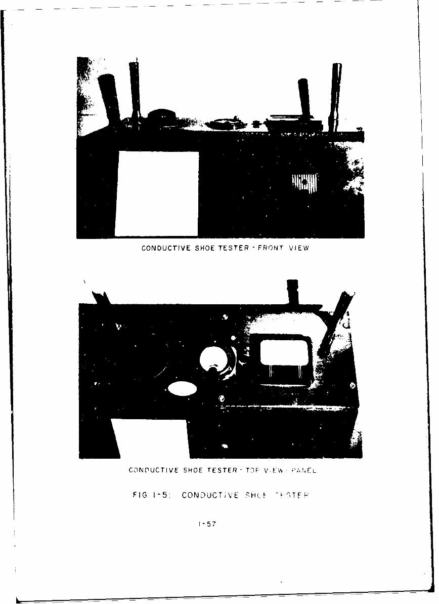
CONDUCTIVE SHOE TESTER -FRONT VIEW
CONDUCTIVE SHOE TESTER - T3F: VIEW. ,'Arqr;
FIG 1-5: CONDUCTIVE cH.•F l TF-'
1-57
Overshoes, rubber boots or rubber-soled shoesthat have no exposed metal may be worn inlieu of conductive-safety shoes by transientsand non-regular area workers. However, theseitems shall not be worn wh3re conductive foot-wear is required unless they pass the conduc-tivity test.
Overshoes, rubber boots or rubber-soled shoesthat have no exposed metal may be worn when nec-essary for cold or wet weather protection inmagazines in which there are no exposed explo-sives, flammable fumes or dust concentrations.However, this type of footwear shall not be wornin magazines containing black powder, either ex-posed or in containers.
D. Perspiration Control
Operators shall wear sweatbands on their foreheadsand take other precautions to avoid perspiration fallingupon material, for example, metal powders and other com-positions, which react with or may be ignited by moisture(see Figure 1-6).
E. Safety Goggles or Eye Shields
Approved safety goggles or eye shields shall beworn by personnel exposed to the hazards of impact,dust, bright flame or splash to prevent eye injuries(see Figure 1-6). This equipment shall be cleanedand maintained in accordance with the manufacturer'sinstructions. The materials in these items must notcontain nitrocellulose or a similar highly flammablematerial. Goggles and eye shields shall be providedfor and specifically assigned to individual persons.They shall not be used interchangeably among person-nel unless they are thoroughly cleaned and treatedantiseptically prior to reissue.
F. Face Shields
Approved plastic face shields shall be worn by per-sonnel exposed to flying sparks, shavings, splashing ofhazardous liquids, etc. (see Figure 1-6). Face shieldsshall be kept away from excessive heat and strong sol-vents that will soften and discolor the shields.
G. Hard Hats
Approved hard hats shall be worn by personnel whenengaged in missile launching pad operations. They shallalso be worn in any other operation that could pos-sibly cause injury to the head (see Figure 1-6).
H. Gloves
1-58

No SUPPRESSORS 604GLES
HNAD HAT
*SH IE D
SWEAT BAND
HEAD, FACE, EYE ANDJL E.-R

Gloves of the proper type shall be provided topersonnel exposed to hazardous materials. The typesof gloves utilized by erployees in the Solid Pro-pellants Area are shown in Figure 1-6.
I. Respiratory-Protective Equipment
1. Design Requirements
"Only respiratory-protective devices approvedby ýhe Bureau of Mines and acceptable underthe U. S. Air Force reguiations shall be used.
2. Type
In general, all respiratory-protective equip-ment can be classified in three (3) majorgroups:
a. Equipment that purifies the inhaled airand makes it breathable.
b. Equipment that require- arn air or oxygensupply from an outsi'e aourk:a.
c. Self-contained brethi- appPAratus tbntprovides its own air or oxygen.
All three (3) of these 6avic classes ofequipment include: a variety cf dev1:es, eachdesigned to jarve best under certain con-ditions. The fundwmental characteristicsof these devices azre summarized as follows:
(1) Air Purifying Equipment
This eqt~lpmeat is suitable for use inatmospheres that contain sufficientoxygen to support life and from whichthe contaminants can be removed orrendered harmless by mechanical orchemical filteri. Included in thisclass of eu4pent are mechanical-filter rospirators, chemical-cartridgerespirators and canister-type gasmabks.
(2) Supplied Air Equipment
(a) Air-Line Respi~rators
"The air-line respirator is usedmostly in unconfined spaces forprotection against paint-sprayvapors, welding fumes, etc.
(b) "ose masks obtain air from an
1-60
uncontaminated source and maybe used in a highly contaminatedor oxygen deficient area.
(3) Self-Contained Breathing Apparatus
A self-contained breathing apparatusoperates independently of the sur-rounding atmosphere. It includes anair or oxygen supply in a cyl 4 ,nder ora method 3f generating oxygen. Equi-.ment of tis type provides completerespiratory protection in any concen-tration of toxic gases and under anycondition of oxygen deficiency (seeFigure 1-7).
1-61

MSA OX(YGEN RESPIR~ATOR
SCOTT AIR -PAK
FIG. 1-7: SELF-CONTAINED BREATHING APPARATUS
1-62
IV. PACKING AND MARKING OF EXPLOSIVES AND A"MUNITION
A. General
The wide range in the sensitivity, stability andhygroscopicity of explosives and propellants hasresulted in the development of varied types of packing.The sensitivity of initiating explosives to shock andfriction and black powder to spark and flame neces-sitates special packing techniques. The effects ofmoisture on the stability of some propellants and thehygroscopicity of many propellants also require specialpacking precautions. Some of these special packingrequirements include the packing of explosives in a wetcondition and the use of airtight-containers that mustwithstand a prescribed internal pressure. The non-hygroscopicity and relative insensitivity of some highexplosives permits the use of collapsible cartons.These cartons may be reused when similar explosives arepacked for interplant shipment or short-term storage.
Bulk priming, pyrotechnic, smoke, tracer and incen-diary compositions are not subjected to shipment orstorage, since they are loaded at the plant where theyare manufactured. Special packing containers, there-fore, are not prescribed for these compositions.
The markings of containers for explosives and pro-pellants are prescribed by the general specificationsand drawings issued by the Air Force, Army and Navy.These also comply with regulations of the InterstateCommerce Commission. The most generally used markingsinclude: the name of the material, lot number, speci-fication number, manufacturer's initials or symbol,ammunition identification code symbol, contract number,date of manufacture, gross weight, cubical displace-ment and the dangerous commodity designation requiredby the Interstate Commerce Commission regulations.Markings may also include the grade and/or class ofexplosives, the plant where they are manufactured andthe box number. Initiating explosives are marked toindicate their nature and compatibility of storing orloading with other explosives.
B. Initiating Explosives
The sensitivity of initiating explosives toshock and friction necessitates that packing be ac-complished while in a wet condition. Due to thelow solubility of lead azide, mercury fulminate,diazodinitrophenol and lead styphnate, water may beused as the wetting agent. However, if shipment orstorage under low-temperature conditions is antic-ipated, a mixture of equal weights of water andethanol is permitted.
1-63

Approximately twenty-five (25) pounds of the explo-sive, wet with not less than twenty (20) per cent ofliquid, is placed in a duct or rubberized-cloth bagand covered with a cap of the same material. The bagis tied securely to prevent leakage. Not more thansix (6) bags are placed in a larger bag of the samematerial. The larger bag is tied securely and placedin the center of a watertight-ometal or wooden barrel,drum or keg that is lined with a heavy, close-fitting,jute bag. The large bag containing the explosive issurrounded with tightly-packed sawdust that has beensaturated with water or a water-ethanol mixture. Thejute bag is sealed by sewing before the barrel, drumor keg is closed. Not more than 150 pounds (dryweight) of initiating explosive is permitted in asingle container.
C. Non-Initiating High Explosives
Nitroglycerin, uncombined with other materials,shall not be shipped by commercial means. Nitro-glycerin should only be used in the place where itis manufactured.
Due to its sensitivity to spark, nitrocelluloseshall be shipped only when wet. It shall contain atleast twenty (20) per cent water by weight and bepacked in watertight drums.
Due to their sensitivity to shock, RDX and PETN mustbe wet with water or an ethanol-water mixture. Theresulting slurry shall contain not less than forty(40) per cent liquid by weight. This slurry isplaced in duct, rubber or rubberized cloth bags whichhold not more than fifty (50) pounds (dry weight) ofexplosive. These bags of explosives are placed ina larger bag of the same material. The small bagsare surrounded with water and the large bag isclosed securely. The bag is then placed in a water-tight barrel, keg or drum. The dry weight of explo-sive in one (1) container must not exceed 300 pounds.During World War II, the Germans packed RDX in a drycondition.
Ammonium nitrate, because of its great hygroscop-icity, is packed in moistureproof-metal drums or paperbags. The metal drums are lined with paper and maybe of the single-trip type. Single-trip drums andburlap-covered paper bag's used for packing ammoniumnitrate have a maxi~num capacity of one hundred (100)pounds.
TNT, tetryl, explosive "D", picric acid, haleiteand nitroguanidine are almost non-hygroscopic. Forlengthy storage or overseas shipment these explosivesare packed in wooden boxes lined with waterproof-paper
1-64

that hold 50 to 100 pounds of explosive (see Figure1-8). For interplant shipment or temporary storagethese explosives may be packed in fiber cartons thatare lined with a waterproof-paper bag that holds ap-proximately fifty (50) pounds of explosives (seeFigure 1-9). These cartons are collapsible and maybe reused. The paper-bag liner is destroyed after thecontents are removed.
The binary explosives: amatol, tetrytol, picratol,torpex and tritonal are generally manufactured at theloading plants where they are to be used and are notsubjected to packing. Pentolite, composition A-3 andcomposition B are sometimes shipped to loading plantsor placed in storage. They are packed in a dry con-dition in fifty (50) pound capicity wooden boxes orfiber drums lined with moisturýproof-paper bags. Theycan be packed in a dry condition since they are muchless sensitive than the PETN and RDX from which theyare made. Composition C-3, when shipped in bulk, ispacked in wooden boxes that are lined with oilproofand moistureproof-paper bags. The capacity of theseboxes is fifty-eight (58) pounds.
Military dynamites and demolition explosives, forexample the C-3 composition, are packaged in one (1)pound sticks or blocks. These explosives are wrappedin oilproof and moistureproof-paper and are packedin paper-lined wooden boxes containing fifty (50)pounds of explosives.
D. Black Powder
Due to its extreme sensitivity to spark and itsgreat hygroscopicity, black powder is packed in air-tight-steel drums that contain twenty-five (25)pounds of powder.
E. Propellants
Propellants are packed in airtight-containers.The hygroscopicity of nitrocellulose propellants andthe adverse effect of moisture absorption on stabilityand ballistic value necessitates this special packingrequirement. Copper-lined wooden boxes, tested forresistance to air pressure of five (5) psi, wereformerly used for all types of propellants and arecurrently standard (see Figure 1-10). These boxesvary in size, the largest holding approximately 150pounds of propellant. More recently standardizedcontainers of stainless steel with a bonded outerlayer of plywood and containers made of heavier, gal-vanized steel have been used (see Figure 1-11). Con-tainers for propellants have relatively large, rubber-gasketed closures of the clamping type with pressureapplied by means of a screw. It is known that pro-
1-65

x 0
ICa Z
0- Z
z <D0 -
CLZ, x
Z40
zX
z (
U,-(jx
U (J0
I-cc

z
w-
w Qz
4 U,Z 0 CC'
w Co
_j Z 0
CoD
CLJz~cJ
0~
020
ww
wwU
0 0
-1-67
FIG.110' WOODEN BOX FOR PAICKING PROPELLANTS
1-68

1 11 21 31 41 51! 61
INCHES
FIG1I-I: STEEL BOX FOR PACKING PROPELLANTS
1-69
pellants stored in these containers do not undergochanges in moisture content even when subjected tothe adverse conditions of tropical storage.
F. JATOS
Small JATOS are generally shipped completely as-sembled. Large JATOS are usually shipped with igniterspacked separately. Certain igniter assemblies and pro-pelling charges (refills) are also shipped separately.The JATO, dependent upon size and weight, may eitherbe packed for shipment in a wooden box, wooden crateor on a pallet. The specific packing required foreach JATO and its separately issued components isdescribed in a technical manual for the specific JATO.Complete packing and shipping data is published in theDepartment of the Army's Supply Manual ORD 3 SNL S-9.
G. Components of Guided Missiles
The components of guided missiles are packed inappropriate types of containers. Fuzes and warheadsare packed in wooden or metal containers. Propel-lants, solid or liquid, are packed in specially de-signed tanks, metal drume, glass bottles or fiber con-tainers in wooden boxes. Control and guidance equip-ment are packed in specially constructed containerssince they are precision instruments. Propulsionsystems are packed in metal crates or wooden boxes.Compressors, cable sets, storage batteries, firingpanels and similar items of special equipment are alsopacked in suitable boxes, crates and containers.
1-70

V. TRANSPORTATION OF EXPLOSIVES AND AMMUNITION
A. General
Railroads, ships, barges, aircraft and commercialand military trucks are the chiei means utilized forthe transportation of explosives and ammunition. Withthe exception of laboratory samples, all railroad ship-ments are accomplished via freight. It is permissibleto ship laboratory samples by express. The shipmentof explosives and ammunition must be made with theutmost care because of shocks during transportation,increased handling and the hazards associated withchanging environment. Problems regarding the safeshipment of explosives and ammunition are similar tothose of storage; therefore, special regulations havebeen developed to insure maximum safety when shippingthese items.
During World War II, some accidents involving ex-plosives and ammunition resulted from handling duringloading and unloading operations incident to transpor-tation. However, any explosion that occurred duringactual transporta~tion in the United States was causedby fire that originated somewhere other than in theexplosive material. In view of the enormous tonnagesof these materialp transported, this record is testi-mony to the effectiveness of the regulations forpacking and shipping explosives and propellants.
B. Ragulations
Published regulations pertaining to tha transpor-tation of explosives are listed below:
1. Interstate Commerce Commission Regulations,Transportation of Explosives and Other Danger-ous Articles by Freight
2. Interstate Commerce Commission, Motor CarrierSafety Regulations, Part Nos. 1 to 7 inclusive
3. Departments of the Army, Navy and Air ForceRegulations and Instructions
4. Bureau of Explosives' Pamphlets No. 6 and No.6A
5. U. S. Coast Guard, Regulations Governing Trans-portation of Military Explosives on BoardVessels and Regulations for the Security ofVessels in Port
6. U. S. Department of Commerce, Bureau of
1-71

Marine Inspection and Navigation's Regula-tions Governing Transportation, etcetera,of Explosives
7. U. S. Civil Aeronautics Board, Civil AirRegulations, Part 49, Transportacion ofExplosives and Other Dangerous Articles
8. Freight Tariff No. 10
9. State and municipal laws and port and harborregulations where applicable.
The above regulations cover the inspection offreight cars, boats, aircraft and motor vehiclesprior to loading with explosive materials. Theyalso cover the loading and staying of shipments, theplacarding of cars and trucks, the labeling of pack-ages to indicate the nature of shipments, the place-ment of freight cars in trains, the inspection ofshipments prior to unloading and the quantities ofitems permitted in individual cars, aircraft, bargesand trucks.
C. Freight Shipments
Freight Tariff No. 10, publishing I.C.C. Regula-tions for the Transportation of Explosives and otherDangerous Articles by Freight, establishes thirteen(13) classes of hazardous materials. Three (3) ofthese classes comprise explosives, propellants,assemblies and ammunition. Some of the militaryexplosives included in these three (3) classes areas follows:
1. Explosives, Class A:
Lead azide Picric acidMercury fulminate Explosive "D"Lead styphnate RDXDiazodinitrophenol NitroguanidineHigh explosives or Haleitepropellant explosives Dynamite
Black powder NitrostarchLow explosives JATh unitsTNT IgnitersTetryl Rocket motorsPETN
2. Explosives, Class B:
Smokeless powder FireworksJATOS Igniters
3. Explosives, Class C:
Blasting caps (1,000 Time-blasting fuseor less) (safety fuse)
1-72
P -'•rs Electric squibsCordeau detonant Delay-electric
igniters
It may appear that Class A explosives include anunduly wide range of materials from the viewpoint ofsensitivity. However, when these explosives are packedas described under the subsection entitled "Packingand Marking of Explosives and Ammunition," which isincluded in this Section of the MANUAL, the factor ofsensitivity may be considered fairly constant for allmaterials in this class. Class A explosives, there-fore, are those substances that represent an explosionhazard in case of fire but not in case of an accidentwithout fire. Accident statistics involving trans-portation substantiate this generalization. Thetransportation of liquid nitroglycerin, as such, byfreight is not permitted and it is not included inClass A explosives.
Class B explosives include materials which areprincipally a fire hazard, Wet nitrocellulose, whichmay be expected to be included in Class B, is includedin the class of fiammable solids. The transportationof dry nitrocellulose via freight is not permitted.Ammonium nitrate, although it has some explosive char-acteristics under extreme conditions, is not includedin Class B but in the class of dangerous articles com-prising oxidizing materials.
Class C explosives contain items or devices thatinclude Class A or Class B explosives as components insmall quantities. These assemblies represent an explo-sion hazard in case of fire. Class C explosives couldinitiate the explosion of any adjacent materials inClasses A and B.
The establishment of these three (3) classes pro-vides for the proper separation of these and otherdangerous articles during transportation via railwayfreight. The extent of damage in the case of accidentor sabotage may be minimized by proper packing andseparation of these materials. The Bureau of Explosivesof the Association of American Railroads is an officialadvisory body on explosives. Its functions are to per-form tests on explosives and offer recommendations tothe Interstate Comerce Commission on which regulationsfor the freight transportation of explosives are based.
D. Motor Shipments
1. The Motor Carrier Safety Regulations of theInterstate Commerce Commission establishthree (3) classes of explosives that cor-
1-73
respond closely with those established forrailway freight shipments. These aredescribed as follows:
a. Dangerous explosives, Class A, include:
(1) High explosives that can be detonatedby a blasting cap, including drynitrocellulose, dry nitrostarch andfireworks that can explode en masse
(2) Black powder and low explosives
(3) Blasting caps and electric-blastingcaps
Items of this class may be shipped ina common motor carrier that consistsof a truck without a trailer. Theymay also be shipped by a semi-trailerattached to a tractor, however, noother form of trailer may be attachedto this vehicle. Liquid nitroglycerinis not included in this class.
b. Less dangerous explosives, Class B, includesmokeless powders for cannon and small-arms and fireworks not subject to explosionen masse.
c. Relatively safe explosives, Class C, in-clude squibs, primers, cordeau detonant,etcetera.
2. Ammonium nitrate is not classified as anexplosive relative to motor transportationbut as an oxidizing material. Separateregulations apply to the transportation ofoxidizing materials.
E. Boat Shipments
Boat shipments are controlled by Coast Guard Regu-lations as found in the Code of Federal Regulations,Title 46. Coast Guard Regulations establish Classi-fications of Class A, dangerous explosives, Class B,less dangerous explosives and Class C, relativelysafe explosives. This division into classes cor-responds to those established by I.C.C. Regulationsfor Motor Transportation.
F. Aircraft Shipments
Civil Air Regulations permit limited shipments of
1-74
explosives and propellants by aircraft. The pack-aging, labeling and classification of these materialsare in accordance with I.C.C. regulations for freightand express shipments.
Passenger aircraft are not permitted to trans-port Class A or Class B explosives except picricacid, explosive "D" and TNT. These explosives mustbe shipped as medical or chemical materials. Theyshall contain at least ten (10) per cent water byweight and be shipped in outside containers havingmaximum contents of sixteen (16) ounces. Class Cexplosives, except blasting caps, may be carried onpassenger aircraft. Individual outside nontainersof Class C explosives shall not contain more thanfifty (50) pounds. Cargo aircraft may transportexplosives permitted in passenger aircraft. Theymay also transport explosives other than blastingcaps that are packed, labeled and otherwise accept-able for express shipment in accordance with I.C.C.Regulations.
I1
1-75

VI. STORAGE OF EXPLOSIVES AND AMMUNITION
A. General
Explosives and ammunition are stored, preferably,in earth-covered, concrete magazines called igloos(see Figure 1-12). Prior to storage these items arepacked in standard containers which include woodenboxes, steel drums, metal crates, cartons, etcetera.For further information concerning containers forexplosives and ammunition see the subsection entitled"Packing and Marking of Explosives and Ammunition"which is included in this Section of the MANUAL.
Magazines shall be located in areas provided withan approved drainage system to prevent moisturedeterioration to items stored therein. Grass or othervegetation adjacent to and extending over igloo mag-azines must be mowed at frequent intervals and alldry debris must be removed. A fifty (50) foot areasurrounding the igloos shall be maintained free fromrubbish, dry grass or other material of a combustiblenature. Trees may remain in magazine areas, providedthey are separated from adjacent woods or forestsby fire lanes or open areas.
B. Magazine Construction
1. General
The magazines used for the storage of explo-sives, ammunition and solid propellants atCCMTA are of the reinforced concrete, earth-covered, igloo type with a barricaded doorend. The present magazines were constructedin accordance with the Corps of Engineers'Ordnance Drawings.
Magazines or igloos are specifically designedfor the type of explosives, ammunition andsolid propellants to be stored. Magazinesused for storing pyrotechnic materials aresimilar to those used for storing primer fusesand detonators. The magazines used to storeboosters, rockets, JATOS and high explosivesare much larger and are shaped differentlythan the pyrotechnic igloos.
2. Shape
Pyrotechnic igloos are square or oblong onthe inside. They vary in length and widthbut are usually only ten (10) feet high.
1-76
0.
U)
z
0.
Magazines housing boosters, rockets, JATOS orhigh explosives are the elongated, arched-rooftype. They vary in length, width and height.
Magazines or igloos are constructed of steelreinforced concrete two (2) feet thick at theside base and tapering to approximately fifteen(15) inches at the breaking point where thearched-roof begins. The arched-roof tapers toapproximately eight (8) inches thick at thecrown.
3. Barricade
Earth-covered, above-ground magazines arecovered with approximately 2 to 3 feet of earthand are sloped at a 2 to 1 pitch.
The barricade at the door-end of the magazineaccess road is constructed of steel reinforcedconcrete (see Figure 1-13). The barricade istwo (2) feet thick at the base and tapers toeighteen (18) inches at the top. It extendsto an altitude higher than the steel doors andis as wide as the front end of the igloo. Thisconcrete wall is backed by an earth-mound on a2 to 1 slope.
The earth covering is seeded and the grass iscut short and maintained in this manner for adistance of at least fifty (50) feet from thebottom of the slope.
4. Floor
The floor is steel reinforced, spark-proofconcrete. It is high pointed at the center togive a one (1) inch slope into lengthwise drainslocated on both sides of the magazine. Thedrains are 2 or 3 inches deep.
5. Lighting
The lighting system contains one, two or fourexplosion-proof spot lights located on thedoor-end barricade which are mounted to directlight into the magazine (see Figure 1-13).
S6. Grounding System
The grounding system is a #1/0 copper cablehooked to end-rings attached to the rein-forced steel of the magazine. These end-rings are located on the outside of themagazine on both sides at the top and bottom.They are connected by a #1/0 copper groundconductor that encircles the igloo. This
1-78
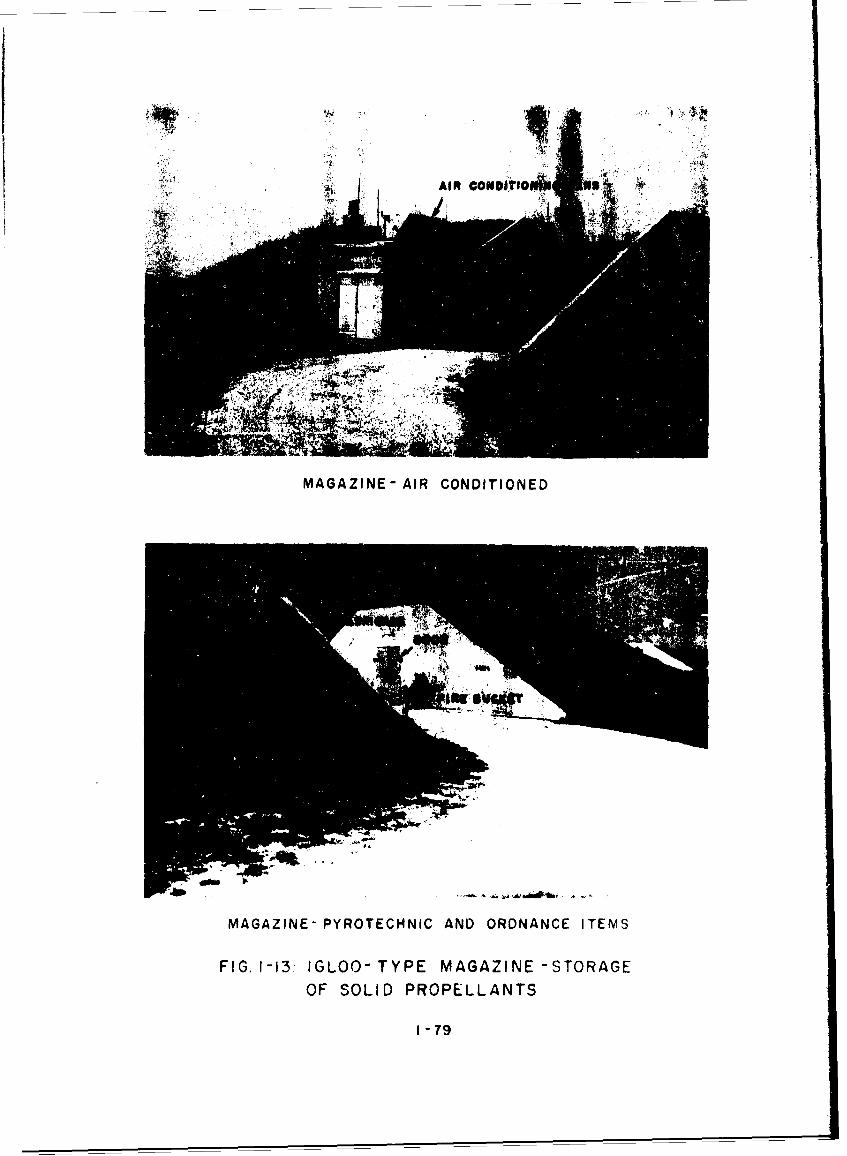
AIR COINDfl1Ib S"
MAGAZINE- AIR CONDITIONED
MAGAZINE- PYROTECHNIC AND ORDNANCE ITEMS
FIG. 1-13- IGLOO- TYPE MAGAZINE -STORAGE
OF SOLID PROPELLANTS
1-79
ground conductor is placed approximatelyeighteen (18) inches below the existing gradeof earth-fill and ground level.
7. Lightning Protective System
Lightning rods are provided at the front andrear of the igloos. They extend two (2) tofour (4) feet above the highest point of theearth-fill and are attached by cable to thegrounding system (see Figure 1-13).
8. Ventilation System
Some magazines are air-conditioned or heat-conditioned, others are equipped with a freshair vent that connects the internal area ofthe magazines to the outside by a duct. Theair vent rises approximately one and one-halfto two feet above the earth-fill of the igloo(see Figure 1-13). A screen installed in theduct prevents rodents, small animals and pestsfrom entering the igloo.
9. Doors
Magazine doors are constructed of 5/8" armor-plate steel on the outside and 1/4" steel plateinside (see Figure 1-13). They are insulatedinternally with asbestos batting. The dualdoors are approximately three (3) inches thick,tri-hinged and are provided with an overlappingat the closure face to insure tightness. Thedoors are also provided with a welded haspfor locking purposes. In some of the largemagazines the dual doors are on rails so thatthey can be opened by sliding.
10. Crane System
Most of the magazines are provided with over-head, chain-operated cranes (see Figure 1-14).These are attached to an I-beam that is anchoredat the rear of the magazine and to the door-end barricade. The I-beam of the crane railextends the length of the igloo to the outside.
11. Access Road
A hard-surfaced asphalt road provides access tothe magazines. The width of the access road istwenty (20) feet for small magazines and thirty(30) feet for large magazines. The road formsa half circle between the front-end barricadeand the igloo. Access is gained from eitherside of the area road.
1-80

LARGE SOLID PROPELLANT ROCKET STORAGE
SMALL SOLID PROPELLANT ROCKET STORAGE
F IG. 1 14 IGLOO-TYPE MAGAZINE - STORAGE OF'SOLID PROPELLANT ROCKETS

12. Fire Symbols or Hazard Markers
a. General
Each magazine is provided with a sign oneither side of the magazine entry way.The signs provide a guide to indicate therelative danger to be encountered by thefire-fighting crews when actively engagedin fighting a fire in the explosives andammunition magazine area. Buildings andstorage sites containing hazardous orexplosive materials must be plainly markedwith the pertinent fire-hazard symbol(see Figure 1-13). The symbol used shallapply to the most hazardous material con-tained within the building or magazine.To facilitate recognition, distinctivebackground shapes have been developed foreach symbol:
,l) Symbol 1 - rectangular-shaped back-ground
(2) Symbol 2 - square-shaped backgrourd
(3) Symbol 3 - dianond-shaped background
(4) Symbol 4 - octagonal-shaped backgi'und
(5) Chemical Ammunition - circular-shapedbackground without explosive components
The symbol background used should be twenty-four (24) inches high and twenty (20) incheswide. The background should be internationalorange or yvllow. The symbol numbers shouldbe black.
b. Chemical Ammunition Symbols
The sme fire symbols shall also be used toidentify chemical ammunition storage facil-ities for fire-fighting purposes. Thetype or types of fire symbols will dependnot only upon the type of chemical agentin the aamunition but also upon the absenceor presence of explosive components in theammurition.
Storage facilities for chemical amwunitioncontaining no explosive components shallbe marked with fire symbols described asfollows:
1-82

(1) A circular sign twenty-four (24)inches in diameter with an inter-national orange or yellow back-ground.
(2) Persistent poisonous gases shall beindicated by two (2) green stripesfour (4) inches wide and four (4)inches apart. These stripes shallbe painted diagonally on the circu-lar sign indicated in Par. (1) andshall extend from upper right tolower left.
(3) Non-persistent poisonous gases shallbe indicated by a single, green, four(4) inch stripe on the circular sign.This stripe shall be centered diag-onally on the sign and it shall extendfrom upper right to lower left.
(4) Incendiaries and other materials whichare not easily extinguished by watershall be indicated by the letter "D".The letter "D" is painted in black onthe international yellow or orangebackground.
Storage facilittes for chemical ammunitioncontaining explosive components shall bedesignate-byexplosi e fire symbols withthe appropriate chemical ammunition symbolsuperimposed on them. This arrangementwill denote the combined explosive com-ponent and chemical agent hazard.
c. Descr'iption of Fire-Hazard Symbols
Symbol 1[] This group consista of explo-sives and ammunition in quantity-distance Classes 1, 11 and 12and faels and oxidizers in classes150 and 1050 when used togetheras propellants. It also includes
solvents, oils, paints, compressed gases andother Inorganic oxidizing agents in sealedcontainers. 1hese materials are principallyfire hazards but minor explosions may beexpected. Fires involving these materialsmust be fought with mobile fire extinguish-ing equipment until the fire has beencompletely extinguished. A mobile firstaid unit must stand by to treat possibleinjuries resulting from the fire.
1-33

Symbol 2
Explosives and ammunition underthis symbol present limited
2 explosion hazards. Personneldiscovering a fire in this type
S:: Jmaterial shall first sound thefire alarm and then attempt to
extinguish the fire with the equipment onhand if the fire is at the incipient stage.When the mobile-fire equipment arrives thefire should be extinguished only when in-dications are that the fire can be ex-tinguished without limited explosions.When the possibility of an explosion isindicated the area should be cleared andthe Fire Department prepared to combatsmall spreading fires resulting from theexplosion and burning debris.
Materials stored under th* Symbol 2include Class 3 explosives and ammunition.These materials include fuses withoutboosters, practice grenades, spottingcharges, JATO-electric igniters, artilleryand cannon primers and primer detonators.
Symbol 3
Personnel in the immediatevicinity of a Symbol 3 fireshall activate deluge systemsand sound the alarm, but theyshall not expose themselves toundue hazards. The Fire
Department shall confine its operation inpreventing the spread of fire to otherbuildings, unless the fire is of a minornature and does not involve the explosiveitself. Fire involving these materialsproduces intense radiant heat over a widearea, which is dangerous to personnel andequipment in the vicinity. Extreme cautionshall be observed by personnel of the FireDepartment when combating this type of fire.
Symbol 3 materials consist of quantity-distance Class 2 and 2A propellants,Group C and D chemical ammunition (notassembled with explosive components) andClass 2 pyrotechnic materials.
1-84

Symbol 4O No attempt shall be made tofight fires involving Symbol 44 aterial except for manualactivation of installedautomatic fire extinguishingequipment. These materials
may be expected to detonate when in-volved in a fire, azd except for explo-sives and ammunition of Classes 4 and 5are subject to mass detonation. Personnelshall leave the building immediately whenthe fire begins. They shall protectthemselves as much as possible and acti-vate deluga systems and fire alarm equip-ment while escaping. When a fire in aSymbol 4 building is small and involvesnon-explosive materials, an attempt maybe made to extinguish it with an extin-guisher or other readily available means.
When the Fire Department arrives, super-vision shall advise them of the nature ofthe fire and the kind of material in-vc'ved or likely to be involved. Whena,.o1 4 materials are directly implicated,fire-fighting forces shall observ strictquar_,iVy-distances (see Air Force andArmy yantity-Distance Classification ofExploives and Ammunition, pages 1-6 through1-25). They shall maintain a distance of1000 feet from fires in which the quantityof explosives involved is 50,000 poundsor less, and proportionately greater dis-tances up to 2000 feet when 100,000 poundsof explosives are involved. Mobile equip-ment shall be kept at a protected location.
When the Fire Chief and Area Supervisorconcur on the procedure, fire-fightingforces may advance to extinguish the fireor protect adjacent buildings. Such actionis never undertaken until the possibilityof an explosion has been eliminated. Undorno circumstances shall a person enter aSymbol 4 building in which there is a fire.
The safety of personnel in fighting aSymbol 4 fire depends on the accuracy ofthe information made available to thefire-fighting forces. No effort shall bemade to fight the fire when the safety ofpersonnel is in doubt. Personnel andequipment shall seek shelter and remainat a safe distance from the building. Firesin igloo-type magazines shall be fought
1-85

only when the contents are determined tobe a fire hazard.
Symbol 4 materials include quantity-distance Classes 4 through 10 explc-sives and ammunition, anr Class 950liquid fuels and oxidizers used aspropellants.
C. Magazine Storage
Containers of explosives and ammunition arestored in magazines in accordance with spocial in-structions, In general, the containers are steredseparately or in stacks with aisles provided betweenstacks and magazine walls. Storing explosives inthis manner facilitates inspection and removal ofthe individual units. Methods of stacking must alsoprovide ample ventilation to all parts of each stack.
Partially filled boxes of explosives must bemarked conspicuously and stored apart from full boxes.Damaged containers of explosives must not be storedin a magazine with serviceable containers. Open con-tainers and containers with insecurely fastened coversare not permitted in storage magazines. No repairwork will be undertaken in ma&azines storing explo-sives. See "Air Force and Army Grcup Suumiary of StorageCompatibility for Explosives and Ammunition," pages1-33 through 1-40 for specific storage requirements.
D. Inspection of Magaziaes and Magazine Areas
1. General Iaspacthon Requirements
Magazines and magazine aruas shall be in-spected ouce a week or more frequently asdirected by local ragulations. These in-spections are neceso~ry to assure thatnormal humidity and temperature are main-tained within the magazine and that allcontainers are tui satisfactory condition.A check should be made during magazineinspections to ascertain that the follow-ing coiditi~n3 p_-evail:
a. The magazine area is adequately protectedagainst fire.
b. Fi-ebrjcai• aze kept clean of rubbish andflammable material.
c. Magazines are properly maintained to insurethat they remain dry, adeluatdly ventilatedand in a general satiLA.actory condition.
d. The interiors of magazines are clean and
1-86

neat with stores orderly arranged.
e. Compliance with the requirements of theAir Force and Army Storage CompatabilityGroups (see pages 1-33 through 1-40) arebeing enforced.
f. The stores are properly identified by lotnumber and stacked so that there is nomore than one (1) lot in each stack.
g. Loose rounds, damaged containers, emptycontainers, paint, oil, waste, rags, toolsand other prohibited articles are notpresent in the magazine.
h. All ammunition and explosives are in seg-regated magazines and not in buildings usedfor other purposes.
i. Records and publications are not kept inmagazines.
J. In the event a magazine contains leakingor exuding ammunition, all personnel must donprotective clothing and equipment beforeentering the magazine. The doors to themagazine shall be left opened until thehazard has been eliminated. The search tolocate and remove the leaking ammunitionshall be conducted under the direct super-vision of the foreman in charge.
2. Special Inspection Requirements
When conducting inspections of magazines, specifickinds of explosives and ammunition shall be in-spected as indicated in the following paragraphs.Any defects noted shall be corrected.
a. Small-Arms Ammunition
Small-arms ammunition shall be inspected todetermine that full boxes are properlymarked and that the seals are intact. Thelids or covers of partially-filled boxesshall be inspected to ascertain that theyare securely closed and that the boxes areappropriately marked,
b. Smokeless Powder
All personnel assigned to, or engaged in,the inspection of smokeless powder must be
1-87

familiar with the characteristics of decom-posed powder. They must also be cognizantof the physical evidence, such as fumes andincreases in temperature, which indicatesthat the powder is in the process of decom-position. Failure to detect a single con-tainer of decomposed powder in a magazinemay result in a fire and loss of an entiremagazine and its contents. Magazines con-taining smokeless powder shall be inspectedto assure that:
(1) Ether or alcohol odors are not presentin the magazine. The odor of ether oralcohol in a smokeless powder magazineis an indication that smokeless powdercontainers in the building are leaking;In sufficient quantity, ether in airis highly flammable and explosive andis readily ignited by sparks, staticdischarge or excessive heat or friction.Ether and alcohol vapors, when present,must be dissipated by ample ventilationto avoid serious consequences.
(2) The contents of leaking containers whendetected must be transferred to service-able containers. The appearance of thepowder may indicate that a surveillancetest should be performed.
(3) The containers are not abnormally warm.This would indicate local heating.
(4) The containers are not subjected tomoisture or dampness.
(5) Visual magazine samples are placed andmaintained in a designated cabinet orrack that is conveniently accessibleand adequately lighted when the maga-zine door is open.
c. Double-Base Propellants
Double-base propellants shall be inspectedaccording to the method prescribed for smoke-less powder. In addition, every effort shallbe made to detect excessive odors of nitro-glycerin or stains on the containers ormagazine floor which might be due to exuda-tion or leakage of the nitroglycerin fromthe powder grains. Any evidence of leakagemust be reported immediately to the super-visor in charge.
1-88
d. Composite Propellants
Composite propellants shall be visually in-spected for the following:
(1) Irregularities in the sbape of grainconfigurations
(2) Cracks in the grain
(3) Air bubbles on the surface o_ the grain
(4) Odor of ammonia indicating decompo-sition.
e. Pyrotechnics and Chemical Ammunition
Pyrotechnics and chemical ammunition arefrequently characterized by a definiteperiod of service. When this period ofservice is exceeded, deterioration may beexpected. Inspectors shall examine mark-iLgs closely to determine the dates ofmanufacture and the expiratiov dates ofstorage. They shall also assure that thecontainers are not rusty, corroded or leak-ing and that they are tightly sealed andthe contents protected against moisture.Special fire-extinguishing agents andsafety equipment furnished to the area bythe Safety Section and Fire Department mustbe examined periodically to assure theirserviceability.
f. Bulk Explosives
Bulk explosives, such as tetryl, TNT,composition B, composition A, explosive Dand black powder, shall be inspected todetermine that all containers are in asecured condition and tightly closed. Itis important that all containers be prop-erly secured in order to prevent leakageand the entry of moisture, dust, rodents,etcetera. Black powder containers shouldbe examined for rust, loose covers andloosened or ruptured seams. Containers offulminate of mercury, lead azide, guncotton and other explosives required to bestored wet with water or watGr-alcoholmixture shall be examined periodically forleaks, corrosion and damage. These con-tainers shall also be examined to determinethat the explosives are actually wet asrequired.
1-89

g. Fuzes, Primers, Detonators and SimilarInitiating Devices
lFuzes, primers, detonators and similarinitiating, devices shall be inspected toassure that they are protected from mois-ture in tightly closed containers andproperly segregated In identified lotsaccording to type.
h. Mortar and Grenade Ammunition
Mortar and grenade ammunition shall beinspected to determine that it is storedand marked in an approved manner and thatall containers are serviceable and securelyclosed.
i. JATOS and Rocket Motors
JATOS and rocket motors shall be inspectedprior to use, with due considerationafforded the following:
(1) Evidence of rough handling of theJATO or rocket motor metal parts orpacking indicates probable damage tothe propellant. When this evidenceappears the JATO or rocket motor willbe segregated for a complete inspectionto determine whether or not they areserviceable. Units declared unservice-able will be dealt with in accordancewith established procedures.
(2) A JATO or rocket motor to be inspectedshall be moved to a safe distancefrom similar units and explosives.They shall also be retained at a safedistance from sources of electricalenergy capable of inducing current inthe JATO or rocket motor circuit beforethese units are unpacked (see Tables 1-3,1-4 and 1-5 in the subsection entitled"Destruction of 1xplosives and Ammini-tion," pages 1-103 and 1-104. Suchinductive sources include power lines,radar units, radio transmitters andother high-powered electrical apparatus.
(3) After their removal from packingmaterials, JATOS and rocket motors
1-90

shall be inspecte! £ the defectsdescribed below y r iy iender theJATO or rocket motor unserviceable.
(a) A shorting device (wire, clip orreceptacle) shall be included onigniter leads or plugs. Forsome JATOS, the igniter leadsare twisted together to short theignition circuit in lieu of ashorting device.
CAUTION: If the shorting deviceis not included or theigniter leads are nottwisted together, shortthe ignition circuit bytwisting the igniterleads together beforeproceeding with theinspection.
(b) Mechanical damage that may renderthe JATO or rocket motor unser-viceable.
(c) The internal presence of moisture,snow, ice, frost and foreignmatter will render the JATO orrocket motor unserviceable.
(d) Evidence of propellant damage,that may sometimes be detected byunscrewing shipping plugs, willcause rejection of JATOS or rocketmotors.
Such damage may be indicated bythe presence of cracked grains,fragolents of propellant, nitrousfumes or musty odors. In general,musty odors, particularly intropical climates, indicate moldand fungus growths.
(e) When required, test continuity ofigniter circuit (see facilitiesfor the non-destructive testingof explosives in Figures 1-15 and1-16).
X. Magazine Safety Precautions
1. Do not store blasting caps in the same magazinewith explosives.
1-91

SOLID PROPELLANT TEST AND SURVEILLANCE BUILDING
SOLID PROPELLANT DESTRUCT PAD AND ROCKET PAD
FIG. 1-15 SOLID PROPELLANT TEST AND
SURVEILLANCE AREA
1-92
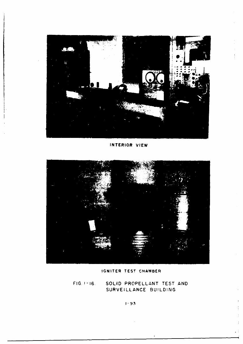
INTERIOR VIEW
IGNITER TES T CHAMBER
FIG. 16. SOLID PROPELLANT TEST ANDSURVEILLANCE BUILDING
1-93

2. Do not allow iron or steel tools or any spark-producing or flame-producing devices in amagazine.
3. Do not store miscellaneous non-explosivematerials in a magazine containing explosives.
4. Do not open cases of explosives in or withinfifty (50) feet of a magazine.
5. Do not wear shoes having exposed nails, metalplates or metal cleats in a magazine. Conduc-tive-type safety shoes are recommended forpersonnel who work in magazines.
6. Do not store primed cartridges or blocks ina magazine.
7. Do not store empty explosive cases in amagazine.
8. Do not throw, drop or slide cases of explo-sives into a magazine. Handle each caseseparately and carefully.
9. Maintain explosives under lock and key at alltimes. Only one (1) person shall be responsiblefor their storage and issue.
10. Do not permit smoking within the magazine areawhich is secured by fencing. Hatches, lighters,etcetera, shall be deposited in boxes providedfor this purpose before entering the magazinearea.
11. Store dynamites and other nitroglycerin explo-sives top side up, so that the sticks lie ina horizontal position.
12. 4eep the floor of a magazine clean at all times.
13. Maintain a fifty (50) foot area around amagazine free of brush, dry leaves and grass.
14. Stack explosives on pallets to provideadequate ventilation and protection againstmoisture.
15. If artificial light Is required in a magazine,use only approved types of electric flash-lights or electric lanterns.
16. Separate partially-filled cases of explosivesfrom full cases. Utilize the contents of thepartially-filled cases before opening full
1-94
cases of the same explosive. Replace the casecover each time after use.
17. Erect a fence around the magazine area to pre-vent stray animals and unauthorized personsfrom entering. Signs shall be posted to warnunauthorized persons from entering the mag-azine area.
18. Stack explosives in a magazine so that the old-est stock of explosives is used first.
19. Firearms, matches, cigarette ligl. ars and anyother types of spark-producing devices mustnot be carried into magazine areas.
20. A record shall be maintained of all itemsissued from a magazine. Unused explosivesshall be returned to a magazine or properdisposition bhall be made in accordance withprocedures established for that class ofexplosive.
l-9•

VII. DESTRUCTION OF EXPLOSIVES AND AMMUNITION
A. General
Explosives and ammunition that have Oecome de-teriorated or devoid of identification shall bedestroyed. Destruction shall be accomplished byburning, detonation or dumping at sea. Buryingexplosives or ammunition or dumping them into wastepits, wells, marshes, shallow streams or inlandvaterways is prohibited except when specificallyauthorized by written instructions.
An Ammunition Disposition Report (ADR) request-ing permission to destroy explosives and ammunitionmust be submitted to the Commander, Air Researchand Deve~lopment Command, through the prescribed chan-ne1.. Disposition shall nor be undertaken untfl theADR is approved and returned by the Commander. Whendisposition is completed the Disposai Olficer willsign and date the ADR and return i. to the Com-mander. Deteriorated explosives and ammunitionthat have been determined to be dangerous to lifeor proparty may be disposed of without prior approvelfrom the Commander, ARDC. In these cases, disposi-tion shall be approved by the PAA Superintendent ofMissile Propellants at CCMTA. However, an ADR mustbe submitted in all instances.
B. Safety Precautions
Safe operations are the major consideration indestroying explosives and ammunition. The "GeneralSafety Precautions" outlined in this MANUAL shall bethoroughly understood and observed by all porsonnel:ngaged in demolition operations. The safety pre-cautions that refer specifically to the destructionof explosives and ammunition are discussed below:
1. Selection of a Site for the Destructionof Explosives and Ammunition
a. By Burning
The site for the destruction of explo-sives and ammunition by burning shall belocated at the maximuin practicable dis-tance from all magazines, inhabitedbuildings, operating buildings, publichighways and railways. Considerationshall also be given to the direction ofprevailing winds and to the possibilityof mass detonation during burning oper-ations. Wherever possible, natural
1-96

barricades shall be utilized between theburning site and operating buildingsand magazines. The burning site shallbe located from all structures and publicthoroughfares by distances comparable to
the "inhabited building distances" (seeAir Force and Army Quantity-DistanceClasses and Tables, pages 1-6 through1-25).
b. By Detonation
The selection of a site for the destructionof explosives and ammunition by detonationshall be based on the same principles asstated in Par. "a" above. This site shallbe not less than 2,400 feet from publicrailways, inhabited buildings, magazinesand operating buildings. When this dis-tance cannot be provided, a pit or trenchshall be used to limit the range of flyingmetal, etcetera. The pit or trench shallbe a minimum of four (4) feet deep and cov-ered with at least two (2) feet of earth.The 2,400-foot limitation does not applywhere substantially constructed destructionchambers are used. Pits will not be re-quired when the destruction of unservice-able or obsolete ammunition occurs on anartillery range or similar sites. Theammunition shall be covered with earth tolimit the range of fragments. This coverof earth should be two (2) feet thick.Demolition charges that are to be coveredwith earth as specified above shall beprovided with detonating-cord leads.These leads shall be long enough to pro-trude through the earth cover into theopen air. Blasting caps are attached tothe open ends of the detonating-cord leadsand are not subjected to the weight,pressure or friction from the earth cover.Electric-blasting caps shall be locatedat prescribed distances from transmittersas described in Par. 6.e. on page 1-102of this subsection. This will mini-mize the danger of an electric-blastingcircuit being energized by strayelectric currents.
2. Burning Combustible Rubbish
Combustible rubbish shall not be destroyedat locations where explosives and explo-sive-contaminated material are destroye.°.When separate burning areas cannot be
1-97
provided, a part of the explosivesdestructiov-burning ground may be reservedfor burning rubbish, provided the two (2)areas are not operated simultaneously.The rubbish-burning area shall be enclosedby a wire mesh or be wetted down prior tothe burning of explosives and ammunitionin the adjacent area. If a wire mesh isused the mesh shall not be larger thanone-half (1/2) inch.
3. Maintenance of Grounds
All dry grass, leaves and other flammablematerials within a radius of 200 feet shallbe removed from the point of destruction.Fire-fighting equipment for combatinggrass fires shall be readily available. Theground at the point of destruction shall bewetted down with water at the close of eachday's operations. The use of concrete matsfor burning or detonation of explosives andammunition is not permitted.
4. Protection of Personnel
Personnel engaged in demolition work shallalways have ample time to reach shelter fromthe destruction site. The shelter shallprovide substantial overhead cover andsplinter-proof protection. The signal fordetonation shall be given by the individualsetting-off the blastings. This signalshall not be given until all personnel inthe vicinity have retired to a protectiveshelter or have reached a safe distance fromthe destruction area. When an electric-blast-ing machine is used, the wires shall notbe connected to the terminals of the blast-ing machine until all persons have reachedcover. The person in charge of the blastingmust be certain that the area is properlycleared of all personnel before initiatingthe blast. Dependent upon local conditions,temporary or permanent barricades shall beprovided and safety distances shall beobserved by all persons. Personnel engagedin burning activities shall be provided withfire-resistant outer clothing. Duringoperations, the number of people in the areaexposed to the hazard shall be kept to aminimum but never less than two (2). Thedemolition or burning area shall be providedwith telephones or two-way radio coomuni-cations. See Par. 6.e. and observe quantity
1-98

distances listed in Tables referred totherein.
5. Safety Distance Requirements for the Prepara-tion of Primed Charges and Dem.olition Charges
Personnel shall take adequate precautions toprevent accidental explosions while prepar-ing primed charges for demolition activities.In addition to the general safety precautionscurrently in force, the following safetyrules for the preparation of primed chargesand comolition charges shall be strictlyobserved.
a. The test-burning of safety fuses todetermine the rate of burning of thefuse rolls shall be accomplished notless than twenty-five (25) feet fromexposed blasting caps or other explo-sives. The test shall be performed inthe direction that the air current ismoving.
b. The fuses shall be cut squarely through,approximately 2 or 3 inches from the endof each roll. The short pieces of fuseremoved shall be discarded.
c. A one (1) foot length of fuse from eachroll shall be cut off and tested todetermine the burning tins of the fuse.This shall be done at the beginning ofeach day's operation arid whenever a newroll of fuse is used. The rate of burn-ing of rolls of old-type fuse (time-blasting fuse) may vary from approx-imately 30 to 45 seconds per foot. New-type fuse (safety fuse U700) burns uni-formly at forty (40) seconds per footand is marked at one (1) foot intervals.
d. The supply of blasting caps for therequired operation shall be located ata miniaum of twenty-five (25) feet fromthe supply of explosives.
e. The preparation of non-electric primeOcharges shall be performed not lessthan twenty-five (25) feet from thesupply of blasting caps or other explo-sives,
f. The fuse used shall be long enough to
1-99

permit personnel to walk, not run, toa place of safety before the chargeexplodes. Fuses less than three (3)feet long or fuses that burn through inless than two (2) minutes shall not be
d used under any circumstances.
S g. A non-electric blasting cap is selected,held open end down and shaken gently toremove dirt or other foreign matter.The desired length of fuse is selectedand held in a vertical position. Thecap is gently slipped over the fuseuntil the explosive is in contact withthe end of the fuse. Do not turn ortwist the fuse in the cap, this actionmay create a spark. If the fuse willnot enter the cap easily, the end of thefuse may be rolled gently between thefingers to facilitate its placement inthe cap.
CAUTION: Do not use force. When the fuseis too large it shall be dis-carded.
h. When the fuse is properly seated withinthe cap, place a standard-type cap crimperover the cap at the fuse end. Hold thefuse and crimp the cap to the fuse. Crimp-ing by other means is not permitted.
i. No more than ten (10) blasting caps shallbe permitted at one time at the siteselected for the preparation of primedcharges.
J. The priming of explosives will be perform-ed at a distance of not less than twenty-five (25) feet from any storage or operat-ing point involved in the preparation ofprimers and demolition charges.
k. From 1 to 6 primed chargza of explosivesmay be utilized depending on the size'ofthe site and/or the charg*%.
1. Primers shall not be prepsred, nor shallexplosives be primed, in advance of therequirements for their us*. Preparedprimed charges that are not used shallbe expended. Such charges shall not bereturned to the explosive storage build-ings.
1-100

a. A limited quantity of explosives suf-ficient to meet the requirements ofthe operation involved shall be broughtto the demolition site.
6. Electrical Hazards
Special precautions shall be taken whenusing electric-blasting caps and electric-blasting circuits during demolitionoperations. These precautions are dis-cussed below:
a. Electric-blasting caps and electric-blasting circuits may be energized todangerous levels xrom outside sources.These sources include static elec-tricity, inducel electric curt-nts,radio cimmunicatior equipment, high-tension wires, etcetera. Safety pre-cautions, therefore, shall be takev toreduce the possibility of a prematureinitiation of the electric-blasting captand explosive charges.
b. The shunt shall not be removed from thelead wires of the blasting cap until themoment the lead wires are connected tothe blasting circuit. The individual whoremoves the shunt shall ground himselfprior to performing this operation, inorder to preveit accumulated Ntaticelectricity from firing the blasting cap.
NOTE: When the blasting cap is testedprior to priming the charge, thelead wires must be short-circuitedimmediately after the test. Thisis done by twisting the bare endsof the wires together.
The wires shall remain short-circuiteduntil the time they are connected to theblasting circuit.
c. When uncoiling the lead wires of blast-Ing caps, the cap shall be held by thewires approximately six (6) inches fromthe cap. The cap shall never be helddirectly in the hand. The lead wiresshall be straightened out as far asnecessary by hand. They shall never bethrown, waved through the air or snapped
1-101

as a whip to loosen the wire coils.
d. Both ends of the firing wires shallalways be shorted or twisted togetherand connected to the ground, except whenactually firing the charge or testingthe circuit. The connection betweenthe blasting caps and the circuit-firing wires shall not be made unlessthe power end of the circuit leads(firing wires) are shorted and grounded.
e. The premature ignition of electrically-initiated devices, such as squibs andblasting caps in a radio frequencyenvironment, constitutes a real hazard.Radio and radar transmitters and otherradio frequency energy-generating systemscreate a field of electromagnetic energyin the air surrounding their antennas.When the lead wires of squibs and blast-ing caps form a resonant antenna enoughonergy may be picked up to cause ignitionof these items. Tables 1-3, 1-4 and1-5 indicate the minimum distance basedon the power of transmitters beyond whichit in safe to conduct electrical-explo-sive operations.
f. There are two possible courses of actionthat can be taken when it is necessary toperform blasting operations at distancesless than those shown in the Tablesnoted in Par. "e" above.
(1) Use a non-electric blasting system.This procedure is preferred in theseinstances because there is no dangerof a premature detonation beingcaused by radio frequency currents.
(2) Use an electrical-blasting system butobserve the following precautions tominimize the possibility of a pre-mature detonation of the electric-blasting cap by induced radio frequencycurrents:
(a) Observe all the usual safetyprecautions governing electrical-blasting operations.
(b) "Snake" (not in a straight line)all firing wires.
1-102
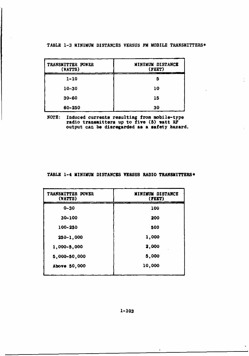
TABLE 1-3 MINIMUM DISTANCES VERSUS FM MOBILE TRANSMITTERS*
TRANSMITTER POWER I MINIMUM DISTANCE(WATTS)1 (FEET)
1-10 5
10-30 10
30-60 15
60-250 30
NOTE: Induced currents resulting from mobile-typeradio transmitters up to five (5) watt RFoutput can be disregarded as a safety hazard.
TABLE 1-4 MINIMUM DISTANCES VERSUS RADIO TRANSMITTERS*
TRANSMITTER POWER I MINIMUM DISTANCE
(WATTS)1 (FEET)
0-30 100
30-100 200
100-250 500
250-1,000 1,000
1,000-5,000 2,000
5,000-50,000 5,000
Above 50,000 10,000
1-103

TABLE 1-5 MINIMUM DISTANCES VERSUS RADAR TRANSMITTERS*
TRANSMITTER POWER MINIMUM DISTANCE(WATTS) (FEET)
5-25 100
25-50 150
50-100 220
100-250 350
250-500 450
500-1 00O 650
1,000-2,500 1,000
2,500-5,000 1,500
5,000-10,000 2,200
10,000-25,000 3,500
25,000-50,000 5,000
50,000-100,000 7,000
100,000 and up 7,000
* Tables taken from OOAMA Munition Letter No. 136-6-23,dated 16 September 1959, entitled "Airmunitions andExplosive Safety."
1-104

(c) A twisted wire such as W-11O-B
or WD-1-IT shall be used.
(d) The full length of all cap leadsshall be evenly twisted when-they are removed from theiroriginal containers.
(e) The number of blasting capsshall be kept to a minimum,preferably one (1).
g. Electric-blasting caps shall be connectedto the firing circuit before they areplaced in or connected to the main charge.This procedure will minimize damage shouldan electric-blisting cap prematurely det-onate due to stray currents. It will alsoserve as a test circuit for determiningthe presence of a dangerous quantity ofradio-frequency current.
WARNING: Individuals connecting the capsshall utilize all availablecover to protect themselves whencompleting the circuit. Thedistance between the individualand the blasting cap shrll beat least the len- c:•e cupleads. AIl s,'.
shall keep --- ... d theblasting cap ., ,. ,g theconnection.
h. Blasting or demolition operations shallnot be conducted during an electricalstorm or during a dust, sand or snowstorm severe enough to produce atmos-pheric static. Blasting or demolitionoperations will be cancelled upon noticethat such a storm is approaching. Alloperations shall be suspended, cap wiresand lead wires shall be short-circuitedand all personnel must be vacated fromthe demolition area to a safe location.
1. Prior to making connections to the blast-ing machine, the firing circuit shall betested with a galvanometer for electricalcontinuity. The individual assigned tomake the electrical connections shallnot complete the circuit at the blastingmacnine or panel, nor shall he give thesignal for detonation until he is assured
1-105
all persons in the vicinity have evac-uated to a safe location. The blast-ing machine or its actuating deviceshall be in this individual's posses-sion at all times during the demolitionoperation. When a panel is used, theswitch must be locked in the open po-sition until ready to fire. The key tothe panel switch shall remain in thepossession of the responsible personduring the operation.
7. Removal of Explosives and Ammunition fromContainers
Explosives and ammunition to be destroyedby burning shall be removed from containers,since any attempt to burn explosives orammunition even under slight confinementmay result in an explosion or detonation.Exuding (leaking) dynamite in boxes is anekception and shall be burned withoutopening the boxes.
8. Determining the Quantity to be Destroyed
The quantity of material to be destroyedat one time will depend upon localconditions. This quantity will be care-fully determined, beginning with a limitednumber and gradually increasing the numberuntil the maximum can be destroyed withoutcausing damaee to surrounding property ordisturbance to civilian areas. The re-sponsible individual will make certain,before he gives the signal for detonetion,that there are no unauthorized persons inthe danger area and that all authorizedpersons are protected by adequate distanceand cover.
9. Collection of Unexploded Amunition
A search of the surrounding grounds shallbe made after each blast and any materialwhich has been thrown from the pit un-detonated shall be collected and includedwith the next charge to be destroyed.Ammunition that has been subjected to anexplosion may be hazardous to handle. Whensuch items are discovered the duds shallbe detonated in the place where they arefound. Fuzed ammunition blown from a pile orpit and not detonated shall not be collected
1-106

due to the possibility of the fuze beingactivated. These items shall be detonatedin the location where they are found.
10. Segregation of Material Awaiting Destruction
Explosives or ammunition awaiting destruction3hall be separated by the intraline distance(see Definitions) from the point of destruc-tion. They shall be protected from grassfires, burning embers and flying fragments.All dry grass, leaves and other flammablematerial within a radius of fifty (50) feetshall be removed from the explosive material.
11. Caution Against Unintentional Ignition
In repeating the burning operation, careshall be taken to guard against materialbeing ignited from burning or smolderingresidue or from heat retained in the ground.Burnings shall not be repeated on previouslyburned-over areas until a period of at leasttwenty-four (24) hours has elapsed.
12. Improvising
The use of improvised methods for explodingblasting caps is prohibited.
13. Misfires
In case of a misfire, personnel shall notapproach the pit, trench or point of deto-nation until a period of thirty (30) minuteshas elapsed. No more than one (1) quali-fied person shall be permitted to examinethe misfire.
14. Use of Trained Personnel
Destruction of ammunition shall never beattempted by inexperienced or untrainedpersonnel. The number of personnel engagedin these operations will be kept to aminimum. More than one (1) person shall bepresent during demclition operations.
15. Guarding Demolition Area
Guards, safety signals and warning signsshall be used to restrict unauthorizedpersonnel from danger areas duringdestruction operations.
1-107
16. Additional Instructions
In the absence of specific regulations or in-formation covering any phase of the destruc-tion of explosive material, instructions willbe requested from the Commander, ARDC, throughthe prescribed channels.
C. Bulk Explosives
1. Black Powder
The safest method to destroy black powder isto dump it in a stream or body of water,provided it is not prohibited by law. Whenno authorized body of water is convenient,it may ba burned. Only tools of wood or non-sparking metal shall be used in opening thecontainers (see Fig. 1-1, page 1-47). Thecontents of only one (1) container shall beburned at a time; no quantity 3hould exceedfifty (50) pounds. The powder must be re-moved from the container and spread out onthe ground in a train about two (2) incheswide. The individual parts of the explosivetrain shall be separated by a minimum dis-tance of ten (10) feet. To ignite the powderbed, use a train of flammable material, suchas excelsior, approximately twenty-five (25)feet long. This material shall be placed soit will burn with the powder in the directionthLt the wind is blowing. The powder trainallows sufficient tive for personnel tosafely withdraw from the area. If the powderwere consolidated into one mass, the flarewould be so sudden and intense that allpersonnel would be endangered. Empty blackpowder containers shall be thoroughly washedon the inside with water, since seriousexplosions have occurred with supposedlyempty black-powder cans. Safety precautions,particularly those outlined in paragraph Bof this subsection of the MANUAL, shall beobserved. Wet black powder may resume itsexplosive properties upon drying. Ammunitionitems which contain small quantities ofblack powder such as fuzes, pyrotechnic items,target practice rounds, etcetera, are to bedisposed of in accordance with prescribedprocedures for the particular items involved.
2. TNT, Composition A, Composition B andComposition C Series, Explosive D, Tetryl,Tetrytol, Pentolite and RDX
1-108
L:

These explosives shall be destroyed by burn-ing. They must not be dumped into water.Although they are not soluble to a greatdegree, they do poison the water. The ex-plosive to be burne~d shall be removed fromcontainers and spread in a thin layer, notmore than three (3) inches thick on a layerof flammable material such as excelsior.The train of flammable material shall bearranged as stated in Par. 1 above. Safetyprecautions outlined in Par. B shall beobserved, No attempt shall be made to burnhigh explosive in lump form. Some of theseexplosives that normally burn when uncon-fined have been known to detonate duringdestruction by burning.
CAUTION: RDX shall be burned wet with waterto prevent detonation.
3. Solid Propellant
Quantities of solid propellant may be des-troyed safely when the propellant isremoved from the containers and spread outon the bare ground in a train 1 to 2 feetwide and not more than three (3) inchesthick. A train of flammable materialapproximately twenty-five (25) feet longand arranged as stated in Par. 1 above, shallbe used to ignite the propellant. This allowspersonnel sufficient time to escape the in-tense heat generated when a solid propellantburns. Safety precautions outlined inPar. B above shall be observed.
4. Dynamite
Not more than one hundred (100) pounds ofdynamite shall be destroyed by burning at onetime. Dynamite cartridges, except frozencartridges, to be destroyed by burningshall be slit lengthwise into halves with anordinary knife. Knives with closing bladesshall not be used. The slit cartridges areplaced in a single layer, not larger in widththan the length of one (1) cartridge. They areplaced on hay, excelsior or other combustiblematerial. The combustible train, arrangedas stated in Par. 1 above, shall be ofsufficient length to allow personnel to
1-109

reach cover or a safe distance before thedynamite begins to burn. The dynamitecontainers shall be burned at the sametime. Dynamite awaiting destruction shallbe shielded from the direct rays of the sun.Sixty (60) per cent dynamite frequentlydetonates after burning a short period oftime. Frozen dynamite is more likely todetonate during burning than normal car-tridges. Destruction of dynamite by det-onation may be accomplished when the loca-tion will permit this method of destruction.Care in priming must be taken to assurecomplete detonation of the quantity to bedestroyed.
5. Other Explosives
Detonation is considered to be the best methodof destroying highly-sensitive explosives suchas mercury fulminate and lead azide. The bagscontaining the explosives shall be kept wetwith water while being transported to thedemolition area. A number of bags (thenumber shall be consistent with safe oper-ation) shall be removed from the containerand carried to the destruction pit. Thebags are placed in the pit in intimate con-tact with each other. Blasting caps are usedto initiate the explosives. The remainingexplosives shall be kept behind a barricadeaffording overhead protection during theoperations. The barricade shall be locatedat a distance that will assure safety.
D. Separate-Loading Propelling Charges
Propelling charges with igniters may be burnedwithout slitting but in all cases the igniter-protector caps will be removed from the charges tobe burned. Protection shall be provided againstpossible explosion and projection of burning par-ticles. Propelling charges shall not be stackedbut will be placed in a single layer for burning.Core-igniter type charges shall be spaced a distanceof one (1) charge from each other.
E. Rockets
Rocket duds loaded with high explosives shall bedetonated in the location where they are found. High
1-110

explosive and practice rockets awaiting destructionshall be destroyed as follows:
1. Rocket heads will be disassembled from com-plete rounds and destroyed in the same manneras a separate-loading shell. The rocket headto be destroyed shall be placed on its sidein a trench or pit approximately four (4) feetdeep. The required quantity of explosive (1/2pound or less of Comp. C per round of ammuni-tion) shall be placed in contact with the sideof the rocket head. The explosives shall beheld in position by earth that shall be packedaround the rocket head. If the explosive usedis a TNT block, it shall be placed on its side.When two (2) blocks are used, one is placed ontop of the other. When three (3) blocks areused. two (2) are placed close together on therocket head and the third block is placed ontop. When five (5) blocks are used, therewill be two (2) layers of two (2) blocks each,with the fifth on top. The demolition blocksare detonated by means of an electric-blastingcap that is wired to a blasting machine. Theymay also be detonated by a safety fuse attachedto a non-electric blasting cap.
2. When disassembly of the rocket head from themotor is not practicable, the complete roundmay be destroyed by detonation. Detonationof the complete round must be performed in amanner that will assure simultaneous and com-plete destruction of both the rocket head andthe motor.
3. When a rocket motor is to be destroyed, thenozzle or nozzle plate shall be removed andthe igniter and propellant withdrawn anddestroyed in accordance with Par. D,"Separate-Loading Propellivng Charges."Rocket motors larger than six (6) inches indiameter will be considered as JATOS anddestroyed accordingly.
F. JATOS
When possible, the nozzle and head-end of theJATO shall be separated from the motor. The igniterand propellant shall be removed and burned inaccordance with Par. D, "Separate-Loading PropellingCharges." If it is impossible or impracticable toremove the propellant, the JATO shall not be destroyeduntil special instructions are received from theCommander, ARDC.
1-111

G. Small-Arms Ammunition
Small-arms cartridges shall be destroyed in a pitapproximately six (6) feet square and four (4) feetdeep. A chute consisting of a piece of two (2) inchpipe shall be provided for this operation. This chuteshall be sloped at an angle that will permit theammunition to slide down the chute and into the pit.The chute shall be placed so one end is over thecenter of the pit and the other end behind a barricade.Precautions shall be taken to baffle the open end be-hind the barricade so the operator cannot look throughthe chute. A fire shall be built in the pit and thepit shall be covered with a piece of sheet iron orother suitable material to confine flying fragments.The cartridges shall be fed into the fire through thechute with care taken to prevent an accumulation ofunexploded ammunition in the pit. A furnace or burn-ing kettle designed for the destruction of small-armaamunition by burning is also satisfactory.
H. Small Components, Except Primers
These components, which include fu~es, boosters,,detonators, firing devices and similar waterial, saybe destroyed either by burning or by detonation.
Relative to the destruction by burning, the soeinstructions given in Par. G. "Uall-Arus Amunition"shall apply to these components. Caution shall beexercised when placing components in the fire, sincenormal action cannot be expected under intense heat.
The sound of an explosion must be hoard for eachcomponent placed in the fire. Another component shallnot be placed in the fire until the explosion of thepRevious one has boon heard. An unusual delay in theexplosion of a component shall not be investigateduntil the fire has burned out and the pit is cold.
When these components are to be destroyed by det-onation, they shall be placed together, in smallnmbers, in an open oontainer. The number to be des-troyed at one time shall be dependent upon the typeand kind of components. The container and componentsshall be placed in a pit or trench four (4) feet deep.One or more TNT blocks shall be placed on top of eachcontainer and in contact with the components. Theseblocks shall be fitted with a type-U1 special electric-blasting cap or with a type-I special non-electricblasting cap and safety fuze. The pit shall then becovered with a layer of logs and earth or otber suit-able cover and the components shall be detonated inaccordance with safety regulations.
1-112

I. Primers
Large primers, 100-grain or %ore, may be destroyedby burning in accordance with the Instructions for thedestruction of small-arms &munition as outlined inPar. 0, "Small-Arms Ammunition " Primers, other thansmall-arms cartridg, primers, are placed in the fireone at a time. Large prusers shall be destroyed onlyin this manner since they are subjected to explosion"en masse' when destroyed by burning in large quanti-ties.
Primers, except the 100-grain or larger primers,may be burned In a trench 4pproximately two (2) feetdeep and one (1) fool wide. The trench shall be ofsufficient length to accommodate the number of primersto be burned at one time. The trench shall be pre-pared with a sufficient quantity of excelsior orsimilar combustible material to insure a fire through-out the length of the trench. The primers shall beremoved from buxes and placed on the excelsior beforeit is lighted.. lastboard cartons need not be openedbefore they are placed in the trench. A piece ofsheet metal shall be placed over the trench to confinefragments as much as possible. After the primers andcover are in place, a train of combustible materialleading into the pit shall be prepared and lighted.Personnel hall then take cover or withdraw to a safedistance from the are% of destruction.
A tank or kettle with a small mesh screen over thetop may be utilized for the destruction of a smallernvuber of primers. The primers are exploded by a firethat is built xndeorneath the tank or kettle. A conven-ient set-up for this purpose is a cylindrical-steeltank that has been cut in half, longitudinally. Theopen side is placed on a steel grating that will retainthe priners In the bank. A twelve (12) Inch hole Iscut In the top center of the half-cylinder tank. Achute or pipe, large enough to accommodate the largestprimer shall be inserted Into the bole. The chuteshall enter the hole at an angle steep enough to allowthe primers to slide down. A hole for a smoke stackto provide draft Is also cut in the half-cylinder tankand a stack is inserted therein. The entire arrange-ment Is rested on stone, brick or earth supports inorder that a fire may be built underneath. Aboutfifty (50) primers are slid down the chute and ontothe grate for each burning operation. Packing material,If flammable, need not be removed from the primers.
The smaller end-vent primers may be destroyed byburning in a fireplace. A steel-mesh basket ofprimers may be pulled onto a grating over the fire-place from behind a barricade. The fire shall be
1-113

started before the basket of primers is pulled overit. When all primers have been fired, the basketshall be pulled off, emptied, cooled, refilled andagain pulled over the fire.
Stock3 of primers awaiting destruction shall belocated not less than 300 feet from the burningoperations. Great care shall be exercised to protectthe pile from accidental ignition by flying frag-ments or sparks. Stocks shall be limited to a one(1) day supply. Other applicable regulations con-tained in Par. B, "Safety Precautions," on page1-96 shall be strictly observed.
J. Grenades
1. General
Grenades may be destroyed by burning or deto-nation. Strict compliance with applicableregulations stated in Par. B, "Safety Pre-cautions," is essential for the protectionof personnel and property. Destruction bydetonation should generally be applied tohigh-explosive grenades, whereas, destructionby burning is applied generally to othertypes of grenades.
S2. Destruction by Detonation
Not more than twenty (20) HE grenades shallbe placed in a destruction pit; the pit shallbe approximately four (4) foot deep. Thegrenades shall be placed in close contact.Three (3) 1/2-pound TNT blocks, taped to-gether, shall be placed on top of the pile.A typo-11 special electric-blasting caparranged for wiring to a blasting machineor a type-I special non-electric blastingcap fitted with several feet of safety fuseshall be taped to one of the three blocks.The grenades and TNT blocks (with leadexposed as described in Par. B.l.b., page1-97) shall be covered with a layer oflightly tamped earth about one (1) footthick. This is accomplished In order toobtain the maxtmm efficiency from the explo-sion of the TNT blocks. The pit shall thenbe covered as described in Par. 8, "'SafetyPrecautions," on page 1-96.
3. Destruction by Burning
A pit two (2) feet square by three (3)feet deep with a loosely fitted steel
1-114

plate or heavy board cover shall be provided.Grenades (other than HE loaded) shall be placedin the fire one (1) at a time. Other grenadesshall not be placed in the fire until the pre-vious grenade has exploded. Care shall be ex-ercised in placing explosives into the fire asnormal destruction cannot always be expectedwhen the greuades are subjected to intenseheat. An unusual delay in the explosion of agrenade shall not be investigated until thefire has burned out and the pit is cold. Aninclined chute baffled at the open end may beutilized in lieu of dropping grenades singlyand covering the pit with the steel plate orheavy board cover each time.
K. Pyrotechnics
1. General
Pyrotechnics, except photoflash bombs and para-chute flares, shall be destroyed in accordancewith the instructions for burning primers (seePar. I, "Primers," page 1-113). Loose pyrotech-nic materials shall be burned under the sameconditions as black powder and the same precau-tions shall be observed (see Par. C.l., "BlackPowder," page 1-108).
2. Parachute Flares
Parachute flares shall be destroyed by burningin the open. The individual flares must belocated at least four (4) feet apart and placedon top of a layer of combustible material.After lighting the train of combustible mate-rial, personnel shall take cover at a safe dis-tance. Personnel shall face away from the fireto avoid injury to their eyes from the extremebrilliance of the flame.
3. Photoflash Bombs
Photoflash bombs are dangerous and shall behandled with car.. They shall be destroyed bythe use of TNT blocks, similar to the procedurefor artillery shells. (This procedure is givenin T.O. 11A-1-37.) Due to the thin case, one(1) 1/2-pound block of TNT is sufficient to ac-complish destruction. Strict compliance withthe applicable regulations of Par. B, "SafetyPrecautions," is essential.
NOTE: Due to the brilliance of the flash ofexploding photoflash bombs, personnelengaged in the destruction operationshall protect their eyes.
1-115

REVISION SHEET
1. Basic Communication February 1960
il . 2-1

Section 2
EXPLOSIVES AND AMMUNITION
I. GENERAL
Missile Weapons Systems are so closely correlated to ex-plosives and ammunition that an understanding of one mustlead to an understanding of the others. The complete function-ing aud composition of all component missile parts must beunderstood by all personnel handling explosives and ammunition.For the component parts of any missile to function properly atthe time and place specified, it is necessary to employ differ-ent types of explosives and ammunition, each having a specificrole, either as a propellant, booster, sustainer, igniter, de-structor, detonator, squib, explosive bolt, etcetera.
An explosive is defined as any substance or mixture of sub-stances that will produce, upon release of its potential energy,more stable substances. These substances are mainly gases.When these chemical compounds or substances are subjected toinitiating impulses or agents such as flame, spark, heat, im-pact or friction (whether applied mechanically, elecLricallyor atomically) they undergo chemical and physical transforma-tion at speeds varying from extremely rapid to virtually in-stantaneous. This results in a sudden and rapid developmentof very high pressure in the surrounding medium. This trans-formation will create more stable compounds, accompanied by aconsiderable and rapid rise in pressure. The generation of alarger volume of gas than originally present and by the evo-lution of large quantities of heat and other forms of energycauses this rapid rise in pressure with consequent expansionof the surroundings. The transformation accomplishes work ofa useful or destructive character, depending on the measureof control exercised over the reaction. Modern military andcommercial explosives include three (3) fundamental types,namely; mechanical, chemical and atomic. This MANUAL willdiscuss only the chemical explosives.
Ammunition is defined as "all the components, and allexplusiven in any case or contrivance prepared to form acharge, complete round or cartridge for cannon, howitzer, mor-tar, small arms or for any other weapon, torpedo warhead, mine,bomb, depth charge, demolition charge, fuse, fuze, detonator,projectile, grenade, guided missile and rocket; all signallingand illuminating pyrotechnic materials; and all chemical war-fare materials."
This Section lists many of the types of explosives andamaunition used in the rocket and missile programs and elabo-rates on those in use at Cape Canaveral.
The chemical explosives included in this Section consistof four (4) types:
2-1

1. Low or deflagrating explosives
2. Solid propellants
3. Pyrotechnic compositions
i4. High or detonating explosives
The distinction between low explosives and high explosivesis not clearly defined. A few low explosives under proper con-
ditions of fineness and packing confinement may detonate uponignition, while a few high explosives when unconfined or com-rressed under very extreme pressures may simply burn whenignited by a flame. Also many texts clLsify solid propel-lants as low explosives, however, in this MANUAL solid propel-lants will be treated as a separate entity because of the manynew developments in propellant compositions.
Black powder and squib compositions will be discussed aslow oxplosives, while high explosives will include the primaryand secondary explosives. A brief treatise of pyrotechnic com-position3 will also be presented.
The dissertation on ammunition will include igniters,ordnance-explosive devices, rockets and rocket motors.
A continuous change of conditions and situations in severalfields of science and engineering requires many different typesof explosives. The operational levels and burning character-istics of these explosives range from the low-pressure explo-sives (black powder and propellants) to the highest high-pressureexplosives (dynamites and high explosives). Therefore, a greatvariety of explosives have been designed -nd used in the variousscientific fields. It has been possible to fulfill the manyneeds for explosives that require specific characteristics byusing only a relatively few explosives and chemical ingredients.This task has been accomplished by combining different combin-ations of ingredients that exhibit different physical proper-ties (density, granulations, etcetera).
Many of the explosives and ingredients shown in Table 2-1have been mixed or consolidated with a chemical additive toproduce the many new high-energy solid fuels being used inthe rocket and missile fields.
2-2
TABLE 2-1 - COMMON EXPLOSIVES AND INGRPDIFZATS
Military Uses Commercial Uses
LOW EXPLOSIVES
Smokeless 2owder, Nitrocotton Smokeless powderBlack powder (potassium nitrate, Nitrocotton
sulfur, charcoal) DNT (dinitrotoluene)DNT (dinitrotoluene) Black powder (sodiumNitroguanidine nitrate, sulfur, char-
coal)
PROPELLANTS
Single-base propellants:Pyrocellulose powderEthyl celluloae powderFlashers and smokeless powderSmall arms powder
Double-base propel 1 ants:Rolled powderCordite powderNitroquanidine (triple base) Very few propellantUulti-and mingle-perforated compomitions are used
stick powders In the commercial ex-Ballistite powder plosive flldBall powderCast double-base propellants
Composite propellants:Polysul fide-PerchloratePo lyurethane-PerchloratePVC Plastisol-ParchlcratePolyester-PerchlorateButadi ne-!VP-rubber
nitrate
2-3
TABLE 2-1 - COMMON EXPLOSIVES AND INGREDIENTS (Continued)
Military Uses Commercial Uses
PYROTECHNIC COMPOSITIONS
Illuminating projectiles Illuminating projectilesTrip flares Airport flaresAirport flares Aircraft landing flaresParachute flares Pyrotechnic signalsReconnaissance flaresAircraft landing flaresBombardment flaresPhotoglash bombsPhotoflash cartridgesPyrotechnic signalsTracersCommunicationsSmoke signalsSimulated ammunition
PRIMARY OR INITIATING HIGH EXPLOSIVES
Mercury Fulminate Mercury FulminateLead Azide Lead AzideDiazodinitrophenol (DDNP) DiazodinitrophenolLead Styphnate Lead StyphnateNitromannite Nitromannite
2-4

TABLE 2-1 - COMMON EXPLWSIVES AND INGREDIENTS (Continued)
Militar'y UsesI Commercial Uses
SECONDARY HIGH EXPLOSIVES
TNT (trinitrotoluene) (Bursting) NG (nitroglycerin)Tetryl (trinitrophenylethyl- AN (ammonium nitrate)
nitramine) (Booster)RDX (cyclotrizethylenetri- TNT
nitramine) (Bursting)PETN (pentaerythritol DNT
tetranitrate) (Booster)Ammonium Nitrate NitrostarchAmmonium Picrate (explosive D) PITH
(Bursting)Picric Acid (trinitrophonol) TetrylDNT (dinitrotoluene)EDNA (ethylenediamine-
dinitrate)
NON-EXPLWSIVE INGREDIENTS
Aluminum Metal NitratesWaxes Metals (aluminum ferro-
silicon)Diphenylamine Wood pulps, metals, other
combustiblesMetal nitrates Paraffin, other hydro-
carbonsMononitrotoluene Chalk, diphenylamine,
wax, sulfur, carbon
2-5

II. EXPLOSIVE TRAIN
The explosives used in rocket motors must be comparativelyinsensitive to impact in order to insure safe handling in trans-it and storage. Sensitive explosives, that can be detonated bythe impact of a firing pin or an electric charge, generally aresafe to handle when they are in small quantities, highly com-pressed and enclosed in a metal capsule. They are used in thatform in fuzes and primers. The small spit of flame from aprimer will not fully detonate a large charge of comparativelyinsensitive explosive, therefore, it is necessary to interposea medium quantity of explosive of medium sensitivity. Explo-sive charges arranged in the order of very sensitive tomedium sensitive to insensitive explosives constitute anexplosive train.
The low explosive or propelling-explosive charge train ina rocket motor consists of the primer, igniter and propellingcharge. This type of explosive train is used for the ejectionor propulsion of a body or a missile from a launching location.It is also used in small arms, cannon and artillery ammunition.
Frequently in missile armaments or jet propulsion weapons,such as rockets and JATOS, a series of explosive elementsincluding primer, detonator and booster make up the igniter.The igniter and propelling charge comprise the explosive train.
A bursting-charge explosive train, which usually makes upthe warhead, consists essentially of a primer, a detonator, abooster and the bursting charge. A delay element sometimes isincluded in the fuze to meet requirements for delay action.
Figure 2-1 illustrates various types of explosive trains.
2-6
-C
0 z 0
w w0I 0
ww co-.
x, wwn z0
- W.;: -.
cr I 0 0 w 0 ww W w U) U
z
C-)
2 0
4t Z
-W w U.
W o4 ;:
w co w L
2-7

III. LOW EXPLOSIVES
A. General
The difference between the various types of explo-sives is based primarily upon their relative speed ofdecomposition. A group of explosives, classified as lowexplosives, is the result of controlling combustion speedsby means of granulation, loading density and confinement(surrounding pressure).
Low explosives are mostly solid-combustible massesthat will, upon ignition, exhibit a burning action rarelyexceeding 0.25 meters per second and will not normallyexplode. The action of slow burning of the solid combus-tibles without shattering or exploding is termed "deflag-ration." Low explosives are frequently referred to as"deflagrating" explosives.
The burning phenomenon of low explosives does not pro-ceed through the mass of the material but burns in layersparallel to the surface until all the material is consumed.Large volumes of gas evolve in a definite and controllablemanner. The burning phenomenon and decomposition of highexplosives is instantaneous and produces a shatteringeffect. In low explosives only a slight shattering effectis exhibited.
The principal characteristics of low explosives are:
1. Controlled burning rate
2. Instantaneous ignition and slow combustion
3. Stability over extended periods of storage
4. Balanced formulation for complete combustionproducing a minima residue and weaponerosion
5. Minimum toxicity and explosion hazard
6. Capability of withstanding mechanicalshock incident to handling, loading,transporting and storage.
B. Black Powder
1. General
The oldest, best known and most widely used lowexplosive is black powder. Black powder is class-ified as a low or deflagrat&±,• explosive. It isdifferentiated from high or detonating explosives
2-8

berause of its progressive slow burning over arelatively sustained period of time in contrast todetonating explosives that decompose practicallyinstantaneously. Black powder is the generic nameapplied to an intimate, uniform mechanical mixtureof charcoal, sulfur and potassium nitrate. Theterm "black powder" also includes compositions ofbituminous coal instead of charcoal and sodium ni-trate in place of potassium nitrate.
Previous to the development of nitrocellulose pro-pellants, black powder consisting of potassium ni-trate was the only propellant and explosive avail-able. Potassium nitrate is used in most militaryblack powders. While no longer used as a militarypropellant, black powder finds application in theignition of smokeless powder, time fuzes, salutingcharges, squibs, smoke-puff charges and catapultcharges. The commercial black powder containingsodium nitrate is used in igniters for rockets,JATOS and missile boosters and sustainers.
2. Composition
The composition of black powder containing potas-sium nitrate, charcoal and sulfur has remainedessentially unchanged for 400 years. Any modifi-cation of the ingredients in proportionate quanti-ties of 75:15:10 has been found to result in thepowder burning more slowly or producing less ef-fect. Standard black powder contains seventy-five(75) per cent potassium nitrate, fifteen (15) percent charcoal and ten (10) per cent sulfur. Itsauto-combustion yields nitrogen, carbon dioxide,carbon monoxide, potassium carbonate, potassiumsulfate and potassium sulfide.
3. Properties
a. Form and Appearance
Black powder varies in form and appearance froma very fine black powder to dense pellets.These pellets may be black or have a grayish-black color because of a polished graphite-glazed surface.
b. Granulations
Military-black powder in manufactured in arange of grain sizes. Each is identified bydesignation, grade, symbol or name.
c. Ignition
Black powder ignites spontaneously at approxi-
2-9

mately 3000C (540°F). It develops temperaturesof combustion from 2,3000 to 3,800*C (4,1720to 6,872*F). These high temperatures causeerosion in the bore of weapons. Black powderis hygroscopic and subject to rapid deteriora-tion when exposed to moisture. If kept dry,it retains its explosive properties indefi-nitely. It is one of the most dangerousexplosives to handle because of its sensi-tivity and ease of ignition from heat,friction, spark, flame or shock.
d. Burning Rate
The type of charcoal used in the manufactureof black powder affects the burning rate ofthe powder. Black powder burns much morerapidly when made from willow or alder char-coal than from oak charcoal. Increase in thepercentage of nitrate, with correspondingdecrease in percentage of charcoal, causes adecrease in the burning rate.
e. Sensitivity
Black powder is less sensitive than tetryl,as proved by impact tests and undergoes noignition in the pendulum friction test witha stool shoo. In the sand test it crushes nosand when ignited by a flame and only eight(8) grams when initiated by tetryl or PZTN.Having an explosion-temperature test value of457*C it is also relatively insensitive tonon-radiant heat energy. Its high degree ofaccidental explosion hazard is attributableto its great sensitivity to ignition by flame,incandescent particles or electric spark.The ballistic pendulum test shows black powderto be fifty-five (55) per cent as powerful asTNT but efforts to detonate it, by means of abooster explosive, have resulted in a maximumrate of decomposition approximately equal to400 meters per second.
f. Stability and Hygroscopicity
Black powder is very stable in the absence ofmoisture. Its ingredients are non-reactivewith each other even when damp or wet. How-ever, black powder when iv contact with eithercopper, brass or steel and in the presence ofmoisture will cause a reaction between themetals and the black powder ingredients. Thisreaction forms side compounds that eventuallyproduce instability.
2-10

Heating black powder above 70°C causes arapid increase in the volatility of thesulfur azd results in a change of compositionand uniformity.
Black powder in undesirably hygroscopic be-cause of the porosity of charcoal or bituli-nous materials and the nitrates.
When used for military purposes black powderis required to contain loes than 0.7 per cent
moisture and is usually dried so that it con-tains only 0. 2 to 0.3 per cent moisture beforeloading.
4. Uses
Although black powder has been replaced by single-base, double-base and composite propellants, it isused in several grades in the following categories:
a. Primers and igniters for artillery shells
b. Delay elements in fuzes
c. sZpelluni chrles for base-ejection smokeshells, Illuminating shells and pyrotechnics
d. Saluting and blank-fire ch1r1es
e. Smoke-puff and spotting charges for practiceammunition
f. Bursters in incendiary ammunition
gt. Burster charges for explosive shells
h. safety fuzes
I. Quick-suatch
J. Spotting charges for practice bombs and shellsand sub-caliber shells
k. Tine-train rings in time and combinationfuzes
1. Igniters In jet propulsion units
a. Slanting operations.
C. Squib Composit ions
Military squibs or low-explosive squibs functionfrom the heat developed by an electrical-resistance
2-11

wire. This heat may ignite a charge of black powdermade from potassium nitrate, sodium nitrate or anignition composition containing:
Per cent
Potassium Chlorate 58
Diazodinitrophenol 40
Nitrost arch 2
Also frequently used is the following matchheadcomposition:
Potassium Chlorate 30
Antimony Sulfide 20
Dextrin 50
These compositions may be used to Ignite the maincharge of black powder.
2-12

IV. SOLID PROPELLIANTS
A. General
Solid propellants contain the necessary chemical in-gredients for combustion or the conversion of their chem-ical energy to useful kinetic energy. One of the ingre-dients is a fuel and the other material is called an"oxidizer." By means of combustion, heat energy isreleased which is eventually converted to kinetic energyof the reaction products. The kinetic energy can becontrolled to propel a solid body, a projectile, rocketor bullet.
A solid propellant used to effect propulsion must becomposed in a manner thav will be compatible with therequirements of the missile system. In evaluating andcomparing solid propellant properties, the following areconsidered important and desirable:
1. A high release of chemical energy
2. A low molecular weight of the combustion products
3. Should be stable and should not deterioratechemically or physically during storage for longperiods of time
4. High density
5. Should be unaffected by atmospheric conditions
6. Should not be subject to accidental ignition
7. Should have high physical strength properties
8. Should have a small coefficient of thermalexpansion
9, Should be chemically Inert during storage andoperation and should not require special mate-rials for chamber or nozzle construction
10. Should lend itself readily to production andhave desirable fabrication properties
11. The performance properties and fabricationtechnique should be relatively insensitive toimpurities
12. A low temperature sensitivity is desirable
13. The wxliauot gas should be smokeless
14. Should lend itself readily to bonding to the
2-13

metal parts, to thie application of inhibitors,to different productio~a techniques and sbouldbe amenable to the use of a simple igniter
15. The rbanhoust should be non-luminous and non-toxic
16. The aethod of prepairation should be simple
17. TIhe conductivity and orecific heat should beEuch as to control heal, transfer of the grain
18. The propellant grain should be opaque toradiation
A9. The propellant should resist aroelon.
Solid propellants are usually considered to unudergoa change by burning only, however, they can also -hedetonated. The ease of detonation doen4ds upon thephyaical state of the propellant.
B. Classification
Solid propellants are classifte'a by their compositioninto three (3) general ty-3s as follows:
1.* Single-base Propo.I ant or MOR~OSRVopGýant
A single-base propellant or monopropullant is asingle, stable cheical compound that does notrequire an added oxidizer but doucomposes tofurnish ito clwn oxidizer st'4 reftcing agent. at*1evato*. temperature. and pressures the** pro-pellants cdeconpopo and convert the beat ofdecoupositi..n into kinetic energy.
Many monopropellants have been developed but thepure nonopropolants bave limit*4 us* because ofpoor stability. Nitrciacluloso, a nitrated raw-cotton, is the ost owi4aly uised sonop~Topellantbut posseaese poor stability. At normal tespera-tureu. pure witrocellulose decomposes slowly andin time vec,04position is couploet. However, withthe us. of chemical additives, nitrocellulose Isquite useful as a single-base or monopropellant.
Other single-bane propellants or vonopropellants(liquid mad solid) being used are. aminiumnitrate, mercury fulminate, pyro-nitrnollulose(pure), aitroglyceria, nitrouannite, picric acid,nit rocel lu lose powders, f lashless-non-hygroscopic(MR) powders, non-hygroscopic (III) powders sandetbyl cellulose (EC) powders.
2-14

2. Double-base or Homogeneous Propellant
A double-base or homogeneous propellant is asingle composition or colloidal phase of oxidizerand reducing agent. This propellant class isoften called colloidal powder.
Many of the pure monopropellants have been blendedor compounded into double-base or homogeneous pro-pellants. This is true of nitrocellulose ani nitro-glycerin blending. Stabilizers, plasticizers andother organic oi inorganic additives are co.Y.li-dated to improve the propertier of double-basepropellants.
Typical double-base propellants now in use are thecordite series propellants, ballistite, "ball pro-pellants," double-base cast propellants, mortarpowders, mall arms, cannon and rocket propellants.
3. Composite or Heterogeneous Propellants
Composite or heterogeneous propellants includecompositione in which the oxidizer and reducingagent are separate entities. A composite propel-lant may be a mechanical mixture of finely powder-ed materials with a binding agent. Gunpowder isa composite propellant with potassium nitrate asthe oxidizer. Carbon is the reducing agent andsulfur is a combination of binder and reducingagent. 'he GALCIT propellant contains an asphalt-oil cr asphalt-resin as a combination fuel binder.The use of lVght metal perchlorates and nitrates,ammonium perchlorate and nitrate, smokeless pr:ý-pellants and lithium perchlorate has indicatedhigh perfornaa-ce composite propellants.
Nor* than oae million organic compounds are knownto be ujod as reducing agents indicating an untoldnamber of the possible corposite propellants thatmay be produced. Also, with the advances in thefields of plastics, resins, polymers and relatedfuel binders, the possibilities of numerous newcomposite propellants are astounding.
It is anticipated that a suitable, pure mono-propellant may eventually be synthesized, how-ever, it appears that a more versatile compositepropellant will result by compounding an oxidizerand a reducing agent to produce the desired bal-listic and physical properties for the idealpropellant.
C. Uses
Single-base or monopropellant compositions are used
2-15

as cannon and small arms powder, propellants, grenades,blasting powders, dynamites and combination mixtures fordouble-base propellants. Double-base or homogeneous pro-pellants can also be used as cannon or small arms propel-lants, mortars, rockets and jet propulsion units. Thecomposite compositions are used in rocket assemblies andjet propulsion units. The choice of a propellant for aspecific use is aetermined by ballistic and physical re-quirements, rather than on the basis of composition.However, a given composition may be suitable for use inseveral different applications.
D. Form
Solid propellants are manufactured in the form offlakes, balls, sheets, cords or perforated cylindricalgrains. The cords and cylindrical grains are produced invarious diameters and lengths and may be extruded, moldedor cast. Numerous shapes are used to obtain various burn-ing surfaces. The burning surface area is determined bygrain configurations that may include either perforations(single or multiple), or star, rosette, cruciform andslotted designs. Figurm 2-2 illustrates several of thevarious forms and shapes of solid propellants.
E. Burning Action
Unconfined propellants burn relatively slow and smooth.When confined the burning rate increases greatly with tem-perature and pressure. The burning of each confined propel-lan- composition exerts a build-up pressure and each com-bustion chamber possesses a pressure limit less than thechamber-eruption pressure. Therefore, the burring surfaceof any solid propellant within an engine must be controlledin order that the permissible chamber pressure will not beexceeded. At any given pressure the rate of burning isproportionate to the propellant surface free to burn andthe area of the throat of the engine nozzle. For thisreason solid propellant grains are manufactured intodefinite sizes, shapes and configurations.
Any form of grain that presents a decreasing surfacearea during combustion is termed a degressive burninggrain. Grains that present an increasing surface area ascombustion progresses are termed progressivo burninggrains. Since tubular or single perforated grains showonly slight change of surface area during combustion, theyare usually referred to as neutral burning grains. Figure2-3 illustrates the comparative burning rates and types ofburning of different shaped propellant grains.
Cord and strip forms of propellant present degressiveburning because the surface of the grain decreases duringcombustion.
2-16

ow lV.OA 46
0 Ob.
06 W
j IL
'I IL
og - 0
w
II
(9 L 0 aijWaj
L1 4mL Wj

00
00Z
000.0
ow
00
UL 0.
IL00 0
Op 0 w0.
0. 0
ww
0 t -
0 U..
IC 0
o U .z 0
00U. J,
t rc)V3j 30ifSrnNal
w 4:

When multi-perforated grains burn the total surfacearea increases. This is caused by simultaneous insideand outside burning. As these grains burn, incompleteconsumption of the unburned propellant remains. Thisunburned propellant is called slivers and may be consumedby afterburning in the bore of th weapop or the combus-tion chamber of a rocket.
Single-perforated propellant grains exhibit neutralburning. As the grain burns the outer surface decreasesand the inner surface increases. The result of the twoactions causes the total surface to remain approximatelythe same in area.
F. Compositions
1. Single-base Compositions
The majority of single-base compositions containa high percentage of nitrocellulose as the mainingredient. Flow Sheet No. I describes the manu-facture of nitrocellulose. In addition to astabilizer, single-base compositions may containinorganic nitrates, nitro-compounds and non-explosive materials as metallic salts, metals,carbohydrates and dyes.
The nitrocellulose is gelatinized by means ofsolvent mixtures (ether-alcohol, alcohol-benzeneor acetone-alcohol). A stabilizer (diphenylamine,2-dinitrodiphenylamine, ethyl centralite, etc.)is consolidated into the gelatinized nitrocellu-lose and the mixture can be extruded into cord,single-perforated or multi-perforated form. Theadditives, such as the non-organic compounds,are incorporated before extrusion and render thepropellants flashless, non-hygroscopic and/orsmokeless.
In the single-base compositions, the organic mate-rials dinitrotoluene and trinitrotoluene act asgelatinizing and moisture-proofing agents and con-tribute some ballistic potential. Dibutylphthalateand triacetin are also gelatinizing and moisture-proofing agents but contribute no ballistic poten-tial. However, they aid in rendering the composi-tion flashless. Potassium sulfate, tin andcryolite serve as flash-reducing agents and thediphenylamines and ethyl centralite act as stabil-izers. Tin also acts as an anti-fouling and ade-coppering agent.
Most single-base propellants are manufactured ina sequence of processes that involves ten (10) ormore operations (see Flow Sheet No. 2). The wet
2-19

JORDAN BEATERS PUMP POACHING
REDUCE FIBER BOIL THREE TIMESSIZE TO REMOVE ACID
SODIUM
9. CARBONATE .
ACID BOILING FILTERING
BOIL AND WASH BLEND INTO WATERTHREE TIMES SLURRY
w CLa a
SPENT ACID J
TO RECYCLE
NITRATION WRINGINGNITRATE FOR 20 CENTRIFUGE TOMINUTES AT 0.8- I.6C 30% FREE WATERIN 85% ACID
SULFURIC
ACID 0
NITRIC V zz 0ACID 0t(3
A o H
SHREDDING FINISHED NITRO-AND DRYING CELLULOSE
SSHRED AND DRY FOR USE IN SINGLE-CONTINUOUSLY AND DOUBLE-BASE
EXTRUDED OR CASTPROPELLANTS
BALED COTTON OR C):EXPLOSIVE HAZARDWOOD PULP LINTERS CLASSIFICATION OF
OPERATIONFLOW SHEET NO. I
MANUFACTURE OF NITROCELLULOSE
2-20
2 ' 8- 8 VZ)W a ~ -J U
WJ~ 20W 0 60WW"
I.- 5Zw D -j IA
CD-0 00 41wO
X0 W jXOw Ug (D M -w - : msz
W W 4 % K
s-i
uw C
> x-
I.00
7W0
2-21 D w 1

nitrocellulose is dehydrated after the moisturecontent has been reduced by mechanical wringing(spin type) to approximately twenty-eight (28)per cent. Further dehydration is accomplishedby compressing (hydraulic block-press) the nitro-cellulose into a block at low pressure (1200-1700psi) eliminating most of the water by flowingninety-five (95) per cent ethanol through theblock under 3500 psi pressure. A block containingapproximately twenty-five (25) pounds of dry nitro-cellulose and about eight (8) pounds of ninety (90)per cent ethanol is obtained. The block isbroken into small lumps by means of a rotatingdrum containing iron prongs and a screen. Thebroken nitrocellulose is then transferred to awater-cooled mixer of the dough-mixer type. Dur-ing this operation ether equal to approximatelytwo-thirds (2/3) of the weight of dry nitrocellu-lose is added. Any plasticizing agents andstabilizers to be included in the composition aredissolved in or mixed with the ether prior to itsaddition to the nitrocellulose. After additionof the ether, materials such as potassium sulfateare added. Mixing of the ingredients is continuedfor about one (1) hour. This produces a partialcolloidal solution that resembles dry oatmeal inappearance. This solution is pressed at approxi.mately 3000 psi, to form a block, thereby rapidlyincreasing the degree of colloiding. The colloid-ing effect is further increased and uniformity ofthe mixture is improved by subjecting it to apressure of about 3500 psi in a macaroni press.The material is squeezed through a series ofscreens and perforated plates and emerges in aform resembling that of macaroni. This macaroniblock is placed in a graining press and extrudedthrough an accurately designed die attached to ahydraulic ram. The pressure is between 2500 and3900 psi. The material emerges as a cord with one(1) or more cylindrical perforations. By means ofa cutting machine the cord is cut into pieces ofpredetermined length. Removal of the volatilesolvent with shrinkage of the grains to theirfinal dimensions is accomplished in three (3)operations. In the solvent recovery operationthe propellant is placed in a large tank and warmair or other gases are passed through the mass.With careful control, t1o prevent surface-harden-ing, the temperature of tihe air is graduallyincreased to not more than 65-C. The solventrecovery operations require from 2 to 14 days,depending upon the size of the grain. This pro-cess reduces the solvent content to approximatelysix• (6) per cent. The "water-dry" operationconsists of placing the partially dried propellant
2-22
in water at approximately 25 0 C and gradually in-creasing the temperature to a maximum of 55°C.After several days (2 to 6), the residual solventis reduced to 0.3 to 5.0 per cent depending uponthe grain size. The propellant is air dried toremove surface moisture and screened to removedust and grain clusters. The final operationbefore packing is to blend all the powder in alot, which may vary from 50,000 to 500,000 poundsdepending on the type of powder. This is accom-plished by transferring the powder from one binto another by gravity flow, the bins being conicalin shape. This blending improves uniformity ofthe lot with respect to average composition andexternal moisture content. Glazing with graphitecan be accomplished during the screening procedure.The graphite glaze is added to facilitite theuniform action of automatic loading machines andto avoid the development of large static electricalcharges during blending and loading.
Typical formulations of single-base propellants
are listed in Table 2-2.
2. Double-base Compositions
Double-base propellants usually contain nitrocel-lulose and nitroglycerin as the major ingredients.In some compositions diglycol dinitrate or penta-erythritol trinitrate are used as a combined fuel-oxidizer in place of nitroglycerin. These majoringredients are accompanied by one or more inor-ganic or organic compounds that insure stability,reduce flash or flame temperature (or both) andimprove ignitability. Other ingredients are addedto aid processing, curing and the physical andballistic properties of the propellant.
The nitrocellulose used in double-base propellantsusually contains 12.6 per cent nitrogen but thenitrogen percentage may fall within a range of12.2 to 13.25 per cent. The supply of glycerinused in the manufacture of nitroglycerin waslimited for many years, but recent developments inproduction of synthetic glycerin have greatly in-creased the use of double-base propellants in theproduction of rocket and JATO solid propellants.
A double-base propellant may contain 39-69 percent nitrocellulose, 19-54 per cent nitroglycerin,1-29 per cent plasticizer, 1-3 per cent stabilizer,1 per cent processing aids and 0.0-1.5 per centsolvent.
Generally, double-base propellants are easily
2-23

TABLE 2-2 TYPICAL FORMULATIONS OF SINGLE-BASEPROPELLANTS
Ingredients Percentage by weight
Nitrocellulose
1. 12.60% N2 79 ... ...
2. 13.15% N2 84.2 --- --- 86.1 98.0 97.7 89.1
3. 13.25% N2 --- 76 ---... ... ...
Dinitro- 9.9 --- 23.0 9.9 --- (x) 7.9toluene
Trinitro - 15.0 --- ---
toluene
Dibutyl- 4.9 --- --- 3.0 --- 2.0phthalate
Triacetin a-- 5.0 .--
Potassium --- --- 1.0 0.75 ---Sulfate
Tin --- --- --- --- 0.75
Diphenyl- 1.0 1.0 1.0 1.0 1.0 0.8 1.0amine-
1. 100.0 100.0 100.0 100.0 100.0 100.0
(x) Coating
2-24

ignited, have high burning rates, high-flametemperature and high force or propulsion.
The solvent process used for manufacturing double-base propellants is very similar to that ofsingle-base propellants. Flow Sheets No. 3 and 4are typical of the processes used in manufactur-ing extruded double-base propellants.
The solvent used is a mixture of ethanol and ace-tone and the solvent recovery procedure isomitted because of the hazard involved in recover-ing solvents containing nitroglycerin. Thenitrocellulose undergoes the same processing forboth single-base and double-base propellants andis blocked and shredded by the same methods.After breaking up the nitrocotton, nitroglycerinis added slowly. Then, consolidation of carbonblack, oxidizer, stabilizer, plasticizer, presslubricant, solvent and other additives isaccomplished in a macerator-type mixer. Thecolloidal mass is then blocked, extruded anddry-cured. In the case of cast double-base propel-lants the base-grain is processed as single-basepropellants. The base-grain propellant is placedin an acetate-restrictor mold. Then the nitro-glycerin-plasticizer-stabilizer casting liquidpermeates the base-grain by means of vacuum.Drying or curing is accomplished by the high-heatplateau method.
Another double-base propellant manufacturingmethod is the non-solvent process. This method isused when the nitroglycerin and any other colloid-ing agent constitues approximately forty (40) percent of the composition.
Due to their hazardous nature, double-base mate-rials are handled under closely controlled condi-tions. The individual materials are almost ashazardous as the combined oxidizer and fuel of thecompounded propellant.
Some of the typical double-base propellant formu-lations are shown in Table 2-3.
3. Composite Compositions
Difficulties encountered in the manufacturing ofdouble-base propellants for rockets and JATOS ledto the development of the composite propellants.The composite propellants are solid, uncolloided,heterogeneous, combustible mixtures consisting ofan organic fuel, an inorganic oxidizing agent andan organic binding agent. Composite propellants
2-25

zz-0 0
0U 0
aaw Z 2UJ j zIm ii
0 wJ z U.UJ z
5 ZO: w 4
ItW W U-.1. x
0 z 0
z z
909 -WIt
w U I- '
LL W t- w juO

o& W
w ow Wi
-j
Wg 0Z JJ
x x w
0I
w
J 20
Le 0 8
00
4; Kha z
W
w
z 0I-- X -
0d Cw
4-.
owISooj
wc .j
c-27

1I 1I aI t
HOca
aq cq
I 1 I ,at o 0 C ca~aa Hq
4'-4
0O noi 4H C
F4 a kq 04
.0 0_ 0
WO.Oa c~ a eq 1boa
~ a2-28

contain neitber nitrocelluluse nor nitrogiycerin.These composite propellants can be manufacturedby a simple mixing operation and molded into agrain of a desired form by compressing or casting.These grains may be coated on the surface withcellulose acetate or other inhibitor materials toaid in controlling the grain burning action. FlowSheets No. 5, 6 and 7 present typical manufactur-ing data for the production of composite propel-lant compositions. Earlier composite propellantstended to become brittle and crack at low tempera-tures. However, recent development of bindingagents less affected by low temperatures hasgreatly expanded the use of this type propellant.
The solid-oxidizing agents that have been used inthe solid-composite propellants include ammoniumchlorate, nitrate, perchlorate and picrate; lith-ium nitrate and perchlorate; potassium chlorate,perchlorate and nitrate; sodium chlorate, perchlo-rate and nitrate.
The use of chlorates of ammonia, sodium and potas-sium has decreased because of their low oxygencontent, white-smoke exhaust and hygroscopicity.Ammonium picrate was previously used in compositepropellants but due to its toxicity, heat andshock sensitivity, it is now seldom used as anoxidizing agent. Potassium perchlorate is beingreplaced by the ammonium salts. Sodium perchlo-rate is deliquescent to a great extent, there-fore, it is not being used.
Lithium nitrate and lithium perchlorate are com-mercially produced and have been added to the in-creasing list of the better solid-oxidizing agents.
Ammonium nitrate and ammonium perchlorate are thesoild-oxildizing agents now being used due to lowcost, low-combustion temperature and a less smoke-less flame when ignited.
The fuel binders used for composite propellantsinclude resins, plastics and organic binders.The casting resins include epoxies, epoxy-poly-sulfides, phenolics, polyesters, polyethylenes,polysulfides, polyurethanes and polyvinyl chlorideplastics.
Table 2-4 indicates a typical basic composition ofa solid-composite propellant.
The more common catalytic agents used to controlthe burning rate in composite propellants areferric oxide, ammonium dichromate, manganese di-oxide, Milori Blue, Monastrol Blue and boron salts.
2-29
-~ a U)
lii Iiie I.--'
W) jW
9- bj~jl
Z4 0 Vu a
o 0 0
Q30 WJ0 CLL
im > W 0 00
2 U)c 2xz W CL
W.A~.W
a. L)-
d)0
x 0.
0w 0 a
a !! _I L
Cd)
0W
250

)o!O a z8.4 N-4 0 0 to 0*~ We~-
0 J on -0 Z4c ;7 -
_j oON UZ 09)Z J
U) me* .6g ;iZc iz- Uq~ It~g~ IL ' weOw to zu -W W N-'(A W J C a ULZ) ir x lwot >
0 wi w 0W Oa
IA) 0 0 z
z It> 004 0>
aw___>_W Wu w
- N OOW o0 0 0 O0 wr
J 0
NW ~W O
>0. 0 .( U 0 -
4c;:ý_ch u oILJ 20Lw ý.. cc Wg21 0

0I
4. 4 4 4
0 -Opl
9- ii. J aal (0) Z -
It qw) wL
wU 0 -w IZ 'Dj -t
w Ill-
0 cc Lg~ ~ 0>OE W L(
o~ 1.. co me a.
0o wg~ICD z "c I
z -w-0 Z
Z J
U) ccn W.
~WO @~ (44Z
N~J~W a. 71" IUMo 0 > w
000~
xfOZ I- __ _ __ _*
N z- 0 0& g- i- w U 4
CDW< a d13
CLu U.C
2 x 0
20 0t ow w
to OU
- 0 - 0
~~~~~ 0IL D ~I
OWV) OW
00
3-52

TABLE 2-4 - TYPICAL BASIC COUIO SITION OF SOLID COMPOSITEPROPELLANTS
Percentage by Ueight
Ingredient High Impulse Low ImpulsePropellant Propellant
Oxidizer 81.0 70.0
Metal (powdered) 2.0
Fuel binder 10.0 23.0
Catalyst 2.3 2.3
Polymer reinforcement 2.0 2.0
Anti-oxidant 0.3 0.3
Curing agent 0.4 0.4
Plasticizer 2.0 2.0
2-33
A few burning-rate modifiers and suppressors aresalicylates of lead and copper; oxides of lead,copper and iron; lead resorcylate; resorcinol;melamine; cellulose acetate and magnesium oxide.
Coolants and anti-oxidants include Flexaiine,1• Lecithin and Cyanoguanidine.
Curing accelerators, catalysts or agents used incomposite propellants are para-quinone dioxime(GMF), tertiary-butyl and cumene hydroperoxide,sulfur, flowers-of-sulfur, benzyl mercaptan,xylyl mercaptan, para-xylene hexachloride anddiphenylguanidine.
The stabilizers used in composite propellants in-clude phthalates, adipates, sebacates, formals,styrenes, acrylates and a few acetate derivatives.
G. Ingredients
The ingredients used in the various solid propollantsare categorized in accordance to their function. Table2-5 is not complete but contains representative compoundsused in the manufacture of single-base, double-base andcomposite-solid propellants. Also, several trade-namecompounds are included in this list since the exact com-position is not known to the authors.
H. Other Propellant Classifications
Other classifications of solid propellants includesolvent or solventless propellants and restricted orunrestricted propellants.
The solvent propellants include the single and double-base propellants processed with alcohol, ether, acetoneand other solvents used to colloidize or consolidate theingredients.
The solventless propellants include the single-base,double-base or composite propellants that are compoundedwithout use of solvents such as alcohol, ether and acetone.These propellants are formed by compressing, rolling, cast-ing or binding.
Restricted and unrestricted propellants relate to thegrain configuration, the encasement and the rate of burning.The restricted propellant grain is a solid bonded-encasedgrain and burns similar to a cigarette.
2-34

TABLE 2-5 - INGIRU09S ( U 3U n PErT RtrA.Yc Fru.CTIMO)USED IN T•13 MIIU7ACflRE OF SOLID PROPELLANTS
ANTI-OXIDANTS, AN'TI-RESOIA 'C AGENTS, COOLANTS AND WETTINGAGENTS
Flexamine Aerosol OTLecithin Uversol Coba tAluminum Cobalt PowderCyanoguanidine Pentaryl ABritish Detergent
BURNING RATE CATALYSTS, BURNING RATE MODIFIERS AND 13URNINGRATE SUPPRESSORS
Ferric Oxide Carbon 31ackAmmonium Dichromate Cupric Oxide (CuO)Manganese Dioxide Basic Cupric SalicylateCupric Chromite Monobasic Cupric SalicylateBoron Ferric OxideCalcined Magnesia (MgO) Lead Oxide (PbO and Pb 3 04 )Monastrol Blue Lead CaproateMilori Blue Lead StearateEpon 562 Lead-li-ResorcylateMagnesium Oxide Monobasic Lead-B-ResorcylateCellulose Acetate Monobasic Lead SalicylateMelamine B-Resorcylic AcidHi-Sil 233 Resorcinol
CURING CATALYST, ACCELERATOR OR AGENT
Sulfur para-Xylene HydrochlorideFlowers of Sulfur tert-Butyl HydroperoxideBenzyl Mercaptan Cunene HydroperoxideRPA-3 (Xylyl Mercaptan Barium Perchlorate
Concentrated in Hydro- Diphenylguanidinecarbon Oil) 1,4-bis (trichloromethyl
Lupersol-DDM Benzene)para-Quinone Dioxime (GiF) BLE-25Magnesium Oxide Zinc Oxide
EXTRUSION OR PROCESSING AIDS AND FILLERS
Candelilla Wax Lead StearateGraphite PhIlbac AStearic Acid Carbolac ICastor Oil Nylon Fibers and Tow
2-35

TABLE 2-5 - loRLDlE1Th (GOtUPID BY PFORIACIU E FUNCTION)USED IN ThE MANUFACTURE OF SOLID PROPELLANTS (Continued)
FUEZ AND FUEL BINDERS
Polysulfide Polymers Methoxyethyl AcrylatePolysulfide, Ethyl-Formal Butadiene-rubber Nitrate
Polymers PolymersPolyvinyl Chloride Resins Isobutylene-IsoprenePolybutylene Glycol mixtures (Butyl rubbers)
Diisocyanate 2,-Vinyl PyridenePolyurethanes Polymer-Resin combinationsEpoxide Resins Butadiene-vinyl PyridineAluminum mixturesAsphalt s AcrylonitrileMethyl AcrylatePolybutadiene Acrylic Acid
STABILIZERS FOR FUEL-OXIDIZER MIXTURES AND FUELS OR OXIDIZERS
Nitrocellulose Ethylenediamine DinitrateNitroglycerin Diglycol DiacetateNitroguanidine Diglycol DinitratePentaerythritol Trinitrate Methyl-anyl-ketone PeroxidePentaerythritol Methyl-ethyl-ketone PeroxidePentaerythritol Acetate
Propionate
FUEL CURING CATALYSTS AND FUEL VISCOSITY ADDITIVES
DicyandiamideBritish Det ergent
Ethyl Cellulose
OXIDIZERS•
Amaonium Perchlorate Barium NitrateAmmonium Nitrate Lithium PerchlorateBarium Perchlorate PotaIssum Perchlorate
PLASTICIZZRS
Dibasic Lead Phthalate Cobalt Octoato In StyreneDiethyl Phthalate Sucrose OctoacetateDimethyl Pbthalate TriacetateDioctyl Phthalate TriacetinDibutyl Sebacate Butyl Carbitol FormalDiethyl Sebacate Di-N-butyltartrattDPiethyl Sebacate Di-(2-ethyl bhxyl Azelate)Dioctyl Sebacate Lead-2-ethyl HexoateDioctyl Adipate 1,4,Butane DiolButyl Carbitol Adipate N, Butyl AcrylateDi-N-Propyl Adipate Triethylene Glycol-DinitrateStyrene Castor OilLechitbin in Styrene Philricb 5 (an aromatic oil)
Resins
2-36

TABLE 2-5 - INGREDIENTS (OGDRU BY PMRFORMANCE FUNrTICN)USED IN THE MANUFACTURE OF 90LID PROPELLANTS (Continued)
STABILIZERS
Barium & Calcium Dodeconate DiphenylamineCalcium Carbonate 2-nitro Diphenylamine (2-NDPA)Calcium Hydroxide Ethyl CentraliteCalcium Phosphate N',N',-diphenyl-diethyl UreaDiallyl Maleate N-methyl-p-NitroanilineDiethylene Triamine tert.-Butyl CatecholMalleic Anhydride Magnesium Oxide
2-37

The unrestrictcd propellant grain, depending uponthe grain configuration, burns internally, internally-externally or externally. This type of burning is shownin Figure 2-4, Solid Propellant Systems. It illustratesthe configuration and the time-thrust surve of severalsolid propellant systems.
2-38

CLI-
w i w
P- zdn
2-39
V. PYROTECHNIC COMPOSITIONS
A. General
Pyrotechnic compoeiticns are classed as low explosivesthat exhibit very little explosive value. This is due totheir lo'i rates of combustion and the liberation of rela-tively little gas per unit weight of composition. Solidproducts of combustion represent more of their mass thanthe gases produced. They produce considerable light andare used extensively for signal and illumination purposes.Pyrotechnic compositions have been used for centuries formilitary purposes but in this century they have becomeimportant because of the increased technical requirementsof modern warfare. Many pyrotechnic compositions havebeen developed for aerial observation, photography, bomb-ing, heat, light, sound and smoke purposes. Also, compo-sitions for tracers, smoke signalling, light signalling,spotting, tracking, delay fuze powders, igniters and in-cendiaries are considered pyrotechnics. All contain sim-ilar ingredients that undergo chemical exothermic reactions.
Physically, pyrotechnic compositions are mixtures offinely powdered elements and compounds that are generallycompressed in candle form.
B. Composition
The important ingredients of a pyrotechnic composi-tion are the fuel and the oxidizing agent. Other materi-als may be added to produce the desired effaccs, such asintensified coloz and decreased burning rzte. These mate-rials may also be effective as binding agunts or water-proofing agents. In the various compos 4 tions an addedmaterial may be effective in more than one cf the foregoingcapacities. The compositions generally ere not chemicallybalanced. Atmospheric oxygen aids in the "cigaretteburning" of the candle-form pyrotechnics and the need for ahigh percentage of oxidizer is not nenessary. This resultsin the use of an excess of fuel and increased light inten-sity.
1. Fuel
Powdered magnesium, LluUMir.u and their alloys aregenerally used as fuels iv pyrotechnic composi-tions, however, calcium silicide, charcoal,sulfur, sil.con, zircunium, titanium and metallic
Shydrides may be used. Me.te:.ials added as colorintensifiers, binding agents and waterproofingagents also act as fuels if they are combustible.
2. Oxidi-e.'s
The principal oxidizing agents used are determined
2-40

by the desired color of light, luminous intensityand burning rate. The nitrates of barium, stron-tium, sodium and potassium and the peroxides ofbarium, strontium and lead are among the most im-portant oxidizing agents used. These compoundscan supply the oxygen necessary for combustion ofmost of the fuel present in a composition. Theremainder of the oxygen is supplied by the oxygenin the atmosphere.
3. Color Intensifiers
The most effective color intensifiers are compoundsof chlorine. Organic chlorine compounds are pref-erable to inorganic compounds because of the hygro-scopicity of many inorganic chlorine compounds andtheir incompatibility with the metals used as fuels.A few of the more important color intensifiers usedare hexachlorobenzene, polyvinyl chloride and chlo-rinated waxes, rubbers and plastics. These agentsdecompose to form metallic chlorides during combus-tion and produce characteristic color bands foundin the flame spectrum. These agents may also serveas fuels, combustion retardants and binding agents.
4. Retardants
Retardants added to pyrotechnic compositions areused to reduce the burning rate of the fuel-oxi-dizer mixture. These retardant materials mustproduce little or no effect on the color inten-sity of the composition. The retardants act asinert diluents or retard the burning rate of themetallic fuels by burning at a considerably slowerrate than the fuels. Calcium carbonate, sodiumoxalate, strontium resinate, titanium dioxide,polyvinyl chloride, ethyl cellulose, paraffin,linseed oil, castor oil, asphaltum and sulfur arethe important retardants in use. Many of thesecompounds act as color intensifiers, fuels, bind-ing agents and waterproofing agents.
5. Binding Agents
Binding agents are generally required to compressthe pyrotechnic compositions into a dense coherentcandle form. The metallic fuels and the inorganicoxidizing agents usually are non-adhesive. Poly-ester and sulfur plastics are the most widely usedbinding agents but polyvinyl chloride, ethyl cel-lulose, metallic resinates, oils, waxes and asphal-tum are sometimes used. Many of these bindingagents perform in a dual capacity.
2-41

6. Waterproofing Agents
Waterproofing agents are necessary in many pyro-technic compositions because of the reactivityof metallic magnesium and aluminum with certainpyrotechnic compounds in the presence of moisture.Also, the nitrates and peroxides are usually hygro-scopic. The waterproofing agents are dried lin-seed oil, acidified potassium dichromate, waxes,metal resinates and natural or synthetic resins.They are used to coat the metallic fuels or maybe distributed throughout the composition.
C. Characteristics of Pyrotechnic Compositions
The important functioning characteristics of a pyro-technic composition are its luminous intensity (candlepower), burning rate, color, color value and efficiencyin light production. The common characteristics forphotoflash compositions are peak intensity, time requiredto reach peak intensity and the integral light in arequired exposure time. Other important characteris-tics must be considered because pyrotechnic compositionsare low explosives and nmut withstand loading, handlingand storage operations. They are sensitive to staticelectricity and radio frequency, impact and friction,ignitability, stability and hygroscopicity. All pyro-technic compositions must have explosive characteristicsas well as pyrotechnic characteristics.
D. Uses of Pyrotechnic Compositions
Pyrotechnic compositions are used in a wide varietyof ammunition products. The most important uses are inprojectiles, flares, photoflash cartridges and bombs,signals, tracers, simulated ammunition, target identi-fication bombs and in nose-cone or war-head recoveryprojects in the rocket and missile programs.
2-42
VI. HIGH EXPLOSIVES
A. General
A high or detonating explosive is a substance in whichthe transformation from its original composition and form,once initiated by suitable means, proceeds with virtuallyinstantaneous, continuous speed throughout the total massof the charge. The high rates of reaction and the highpressures are accompanied by the evolution of a large gasvolume, heat, noise and a widespread shattering effect.The extreme rapidity of decomposition, termed "detonation,"takes place in a manner similar to rapid combustion orwith rupture and rearrangement of the molecules of thesubstance. The disruptive effect of the reaction causesmany explosives to be valuable as bursting charges butprecludes their use as a propellant. The gases formeddevelop excessive pressures that may burst the combustionchamber or the barrel of a weapon.
The compositions of high explosives usually containnitrated products of organic substances or nitrogen con-taining inorganic substances. They may be mixtures ofboth. A high explosive may be a pure compound or an inti-mate mixture of several compounds. Ingredients that im-part desired stability and performance characteristicsare added.
High explosives are divided into primary and secondaryexplosives. The principal difference between primary andsecondary explosives is the means of detonation. Primaryhigh explosives are detonated by means of simple ignition,including spark, flame, impact and other primary heatsources. Secondary explosives require a detonator andfrequently a booster for actuation.
The detonator used to detonate secondary explosivescontains, as the essential element, a primary high ex-plosive that is easily ignited. The detonator may bemore complex it constructed with timing devices, safetymechanisms and other special features. The booster con-sists of a highly sensitive, secondary high explosivethat reinforces the detonation wave to the main explo-sive charge. The main explosive charge is a secondaryexplosive.
B. Primary or Initiating Explosives
Primary or initiating high explosives include primarycompositions and initial detonating agents.
1. Priming Compositions
Priming compositions are physical mixtures ofmaterials that are extremely sensitive to impact
2-43
or percussion, The material mixtures may includethe initial detonating agents; lead azide, mer-cury fulminato or lead styphnate. The applicationof impact or percussion to these mixtures causesvery rapid auto-combustion but not detonation.The detonation is prevented by the dampening effectof added inert ingredients such as antimony sul-fide, lead thiocyanate, ground glass or sulfur.
The products of auto-combustion of priming compos-itions are hot gases and incandescent solidparticles.
The pr.ming compositions consist of physical mix-turf : *e or more initial detonating agents,fuels, desensitizers and binding agents.
The oxidizing agents used in priming compositionsare potassium chlorate and barium nitrate. Thefuels used are lead thiocyanate, carbon black,antimony sulfide and calcium silicide. Antimonysulfide and calcium silicide are also used tosensitize the compositions to friction or percus-sion. Carboruadum and ground glass are used assensitizers. The explosive ingredients generallyare the sensitive-initiating compounds or the non- ,ialtiating compouuds. Shellac, gum arabic andgum tragacanth are the major binding agents usedand may also serve as fuels.
Priming compositions are used for the ignitionof initial detonating agents, black powderigniter charges and propellants in small armsammunition.
2. Initial Detonating Agents
Initial detonating agents are high explosives thatare extremely sensitive to heat, impact and fric-tion. They undergo detonation when subjected to aflame or percussion. They are used to initiatedetonation of the lesser sensitive high explosives,comprised of bursting charges, demolition high ex-plosives and dynamites. Most initial detonatingagents have lower rates of detonation and brisancevalues than the explosives they initiate. Sincethey include azides, fulminates and diazo-, nitro-and nitroso-compounds, several of the initialdetonating agents used are less stable than thenon-initiating explosives. Many compounds thathave satisfactory initiating characteristics aretoo unstable or sensitive for use in ammunition.Consequently, those in use as initial detonatingagents are limited in number.
2-44

The initial detonating agents in use are:
Lead Azide
Mercury Fulminate
Diazodinitrophenol
Lead Styphnate
Tetracene
C. Secondary or Non-Initiating Explosives
1. General
Secondary or non-initiating high explosives includeexplosives that require initiation to detonationby another explosive. They are used as boosters,bursting charges, blasting charges and demolitionmaterials. They may be divided into the followingtypes:
a. Single-Compound Explosives
b. Binary Explosives
c. Plastic Explosives
d. Dynamites
2. Single-Compound Non-Initiating High Explosives
Single-compound high explosives include inorganicand organic compounds. Ammonium nitrate is themost widely used inorganic explosive. The organiccompounds include nitrates, nitro-compounds andnitroamines. These organic compounds are nitro-cellulose, nitroglycerin, nitroguanidine, nitro-starches, trinitrotoluene (TNT), Explosive "D",cyclonite (RIm), pentaerythrite tetranitrate(PSTN), haleite and tetryl.
3. Binary Non-Initiating Explosives
There are three (3) types of binary explosivesmanufactured. One is produced by mixing tri-nitrotoluene (TNT) with another explosive. Asecond type is made by mixing TNT with anotherexplosive and a non-explosive material suchas aluminum. The third explosive contains TNTand powdered aluminum. The aluminum increasesthe temperature of the explosive and decreasesthe brisance but gives the explosive a highblast potential. Binary explosives are superior
2-45
to TNT with respect to fragmentation and blasteffect. Binary explosives are amatol, tetrytol,picratol, torpex, tritonal, ammonal, pentoliteand ednatol.
4. Plastic Non-Initiating Explosives
The development of two (2) types of plastic non-initiating explosives was the result of limita-tions involved in the melt-loading of other explo-sives with TNT. Also, two (2) other requirementsbrought about this development, namely, the re-quirement for a highly brisant explosive thatcould be press-loaded without undue hazard andthe need for a demolition explosive that could behand-shaped.
RDX (cycloerite), a high brisant explosive, wasselected and mixed with other explosive or non-explosive materials to produce the plastic ex-plosives.
One of the two types consists of RDX and a desensi-tized wax in a mixture suitable for press-loading.The other type consists of RDX and a binding agentthat forms a putty-like mass capable of being hand-shaped.
The plastic explosives now in use include theseries of Compositions A, B, C and D.
a. Compositions A A-2 and A-3 are composed ofninety-one (91) per cent RIX (cyclonite)and nine (9) per cent wax. The RDCX will varyin granulation and the wax may be either bees-wax or petrolem-derived wax.
b. Composition B consists of a 55:40:5 mixtureof RDX to TNT and a desensitizing wax.
c. Compositions C, C-3 and C-4 are plastic demo-lition explosives that can be shaped by hand.
Composition C contains an eighty-eight (88)per cent RM and twelve (12) per cent of anon-explosive oily plasticizer.
Composition C-3 contains seventy-seven (77)( per cent RDC and an explosive plasticizer
containing mononitrotoluene, a liquid mixtureof dinitrotoluenes, TNT, tetryl and nitro-cellulose.
Composition C-4 contains ninety-one (91) percent RIU and a desensitized mixture of poly-
2-46
isobutylene, motor oil and di-(2-ethylhexyl)sebacate.
d. Composition D-2 is a desensitized explosivemixture consisting of eighty-four (84) percent paraffin and other waxes, fourteen (14)per cent nitrocellulose and two (2) per centlecithin.
5. Dynamites
Operations requiring explosives, other than thestandard military high explosives, for excavation,demolition and cratering must resort to the useof comercial blasting explosives. These blast-ing explosives, with the exception of black pow-der, are referred to as the dynamites. Mostdynamites consist of high percentages of nitro-glycerin and sodium nitrate, some carbonaceousmaterials, sulfur and an antacid. The dynamitesmay be exploded by flames, sparks, friction andsharp blow*, including impact from bullets orshell fragments. They are subject to relativelyrapid deterioration and require constant surveil-lance. Dynamites freeze at low temperatures andmust be thawed before use. Dynamites may be ex-ploded by a number-6 or larger commercial blast-ing cap or by the Corps of Engineers' specialblasting cap. Dynamites are classified asstraight, ammonia or gelatin dynamite.
a. Straight dynanito contains nitroglycerin asthe explosive ijnredient and a non-explosivefiller. It has a high velocity of detonationthat produces a shattering action. Straightdynamite is water resistant to a small degree"and may be "ad underwater only if fired with-in twenty-four (24) hours after submersion.
b. A contains amonium nitrate,Indditin to nitroglycerin, as the explo-sive base. It has a medium velocity of det-onation which produces a heaving action.It is not satisfactory for underwater use.
c. Gelatin dyu4te is a jolly made by dissolv-172 altrocotton in nitroglycerin. It Ishighly water-resistant and suitable for useunder vet conditions.
Specif in data concerning the composition, type,strength and usage of these commercial dynamitesmay be obtained from the manufacturers.
2-47

VII. IGNITERS AND IGNITION
A. General
The effectiveness of a rocket depends upon the steady-state burning of the contained propellant system. Thesteady-state of propellaiut burning is always preceded byone or more transient processes designated collectivelyas the "ignition process." The ignition process is per-formed by a device known as a- "igniter."
.,he igniter of a rocket motor must perform two (2)functions. One is to heat the propellant grain to igni-tion temperature and the other is to increase the combus-tion chamber pressure to a point where the reaction ofthe propellant responds satisfactorily. An igniter shouldaccomplish these functions with only milliseconds of delaybut without creating undue high pressures that will sub-ject the propellant grain to excessive forces.
Primary initiation of an igniter is electrical in themajority ol the present rocket motors because the locationof the igriter in the rocket motor usually prohibits theuse of a percussion type ignition system.
A type of igniter assembly (see Figure 2-5) consistsof one or Aore electric squibs (electr•.c match or initi-( ators) aud an igniting charge of black powder or pyrotech-nic composition housed in a container. Leads (electricalwires) from the squibs are passed from the igniter housingto an external point where they can be attached to theelectrical circuit. The squib contains a heat-sensitivecomposition that is initiated by the generated heat causedby the electrical impulse that passes through the electriclead wires. The ignition heat of the squib c&uses the ig-nition of the black powder and it then ignites the propel-lant. The black powder may contain a booster charge ofother explosive materials. When more than one (1) squibis provided in an igniter the squibs are wired in parallelto provide assurance against misfires. For safety duringhandling, storage and shipment the igniter leads areshorted to prevent accidental ignition by stray or inducedcurrent or other sources of electrical energy.
B. Ignition of Solid Propellants
Many solid propellants are ignited by a small quantityof black powder. The black powder is ignited by means ofan electric match. The igniter consists of the electricmatch and the igniter material (black powder) encased in acontainer. An electric current applied to the lead wirqsof the squib produces sufficient heat to ignite the sensi-tive electric match or squib. The flame from the electricmatch spreads rapidly through the powder charge in the
2-48
ELECTRICAL LEADSTO FIRING CIRCUIT\
CLAY BODY
HEAT- ELECTRICSENSITIVE EleMATERIAL
CASE • BRIDGE WIRE
IGNITER CHARGE-(USUALLY BLACK POWDER)
FIG. 2-5: A TYPE OF IGNITER ASSEMBLY
2-49

igniter, increasing the internal pressure until the ig-niter case Is broken open. The products of decompositionof the igniter material transfer energy to the propellantby the t'ee (3) mechanisms of energy transfer, includingconduction, convection and radiation. The impingemeat oft~e hot, solid particles of the igniter material causesthe propellant to ignite and burn in parallel layers.This burning produces hot gases and an Increase in pres-sure that causes the propulsion of the rccket.
C. Igniter Design
Igniter design is influenced by the size and shape ofthe propellant grain and its composition, the location ofthe igniter in the rocket chamber and the free volume in-side the ro)cket chamber. Therefore, design of an igniterfor a rocke' is usually the final step in rockat and mis-sile lesI:n. The experience gained from trial and errorresults in frequent changes to igniter designs.
Generally, the design criteria for an igniter indi-cate3 a plastic or metal case containing an initiator andigniter materibl. The initiator is an off-the-shelisquib o;. a known electric match composition. However, theigniter materials vary according to the igniter perform-ance required. Past and present igniter materials areblack powder and double-base rolled powder or mixtures ofboth. Current and future missile programs indicate theuse of borane pellets as igniter material.
Other principal design considerations for igniters are:
1. The type, grain size, formulation and moisturecootent of the igniter propellants
2. The size, direction, shape and temperature of theignition flame
3ý The location of the igniter with respect to the
main charge
4. The surface condition of the main charge
5. The quantity of hot solid particles in the ignitergases
6. The quantity of debris ejected through the nozzle( at the start
7. The -'-zzle closure rupture pressure
8. The time-pressure relationship between igniterpressure and the operating pressure of the rocket
9. The time delay between tha Qlectrical signal andthe first pressure rise.
2-50

10. The construction, fabrication and fastening ofthe igniter case
11. The electrical energy.
D. Initiators
The electrical initiators or squibs consist of two (2)mbedded electric leads and a bridge wire that short cir-
cuits the leads. The bridge wire is heated by the passageof an elect-ic current. A heat-sensitive material isnormally applied as a bead to the bridge wire. The o~delectric match or initiator contained a clay body and aprimer mixture ibuttered" around the bridge wire at theend. Later designs have enclosed the entire unit in ametal or plastic jacket, added a booster charge of blackpowder or other pyrotechnic mixtures and replaced the claybody with a rubber plug or a ceramic or glass insulatorin a metal body.
Primer mixtures for the squibs may be mercury fulmi-nate, lead styphnate or more complex mixtures of nitro-starch, lead azide, potassium chlorate and antimony sul-fide. Gum arabic, red gum or a synthetic resin is usedas a binder.
E. Igniter Materials
The original and most conmon igniter material isblack powder, available in several mesh sizes rangingfrom a fine powder to very coarse granules.
Difficult ignition of igniters, used under adverseconditions, has brought about the addition of other mate-rials to assure initiation, avoid misfires and producehigher temperatures and pressures. These materials, addedto black powder, are chopped trench mortar sheet powder(double-base rolled powder), boranes and powdered metals.
Metal oxidizing agents have replaced the black powderin many of the njwer ignition systems. The most commonof these are magntaium or aluminum powder and potassiumnitrate or perchlorate. Granular mixtures usually reacttoo rapidly and the mixtures are usually pressed into avariety of different sizes and shaped pellets.
F. Igniter Containers
Originally the igniter containers for rockets werecotton cloth bags. These bags, which contained smallquantities of black powder and an electric match composi-tion, were closed and tied tightly with string. Contain-ers of this type are used occasionally in experimentalwork. Due to the hygroscopicity of most igniter mate-rials, a hermetically sealed container of a stronger,more endurable construction is required.
2-51
Many of the plastic containers, produced by an inex-pensive rapid molding process, could be sealed againstmoisture. However, they were unsatisfactory because oftheir brittleness, reaction with the propellants and in-stability at elevated temperatures. New developments inplastics have again stimulated the use of hard, stableplastic containers.
The most widely used container for igniters at presentis the common tin can that can be hermetically sealed. Ithas good handling properties and permits filling so thatthe contents can be tightly compacted. The tin-can con-tainer is not ejected when the rocket functions, instead,it ruptures or the cover is blown off.
Many igniters are now made with the container servingas a part of the rocket. These parts may be a head clo-sure, part of the nozzle assembly or a part of the combus-tion chamber. In other cases the initiator and ignitercontainer may be combined into a single unit, the bodybeing machined from aluminum or steel. When more substan-tial containers are used, they should have a built-inrupture or blow-out mechanism that is reasonably preciseto the condition under which it will rupture. These re-finements are necessary when low variability in igniterperformance is required.
k G. Igniter Types
The designs of various types of igniters for solidpropellant rocket motors (see Figure 2-6) frequently arepredicated by the shape of the grain configuration. How-ever, their specific shapes are governed more by theirlocation in the rocket chamber. The location of the ig-niter in the chamber is decided by the specific require-ments imposed. Most rocket designs place the igniter inthe front end of the rocket so the reaction products ofthe igniter will sweep over the entire length of the pro-pellant grain. Some rockets use nozzle-end or internaligniters.
1. Head-end Igniters
Rockets utilizing fin-stabilizers have a rela-tively large length-to-diameter ratio. Conse-quently, space for an igniter is usually avail-able at the head end of the rocket. Ignitersfor small caliber rockets will have a smaller( outer diameter than the inner diameter of therocket chamber. In larger rockets, the ignitermay be a large can located in the center of thehead closure or it may be in the form of a torusor a ring. The larger units have several squibsconnected in parallel to insure functioning ofthe igniter and to increase the effectiveness of
2-52

Uz wCL 0 zj '
oz J~ w0 a
P w > W-
E 0 0
- z w00
0Z 0! * at o I-U
ItJo"u.ush
I.- hL
0 u W 'j
31 0 0.~.
In 4
-I 00.hi 0
w. wj LLnz Q
W IL
0 a
It 9 1
J 0
o g o 2 In c0 0w - m I
I~ hij ZL
2-L5
the burning of the large quantities of igniter
materials.
2. Nozzle-end Igniters
Rockets of the spin-stabilizer type have severelimitations on over-all length and any increasein length to accommodate an igniter is prohibi-tive. Therefore, the igniter used in this typerocket is usually a nozzle-end igniter. A nozzle-end igniter is usually located in the center ofthe nozzle plate with the multi-nozzles locatedin a ring around it. By building the igniter intothe nozzle plate the need for a container, as well"as the possibility of container fragments pluggingthe nozzles, is eliminated.
Nozzle-end igniters may be used in single ormulti-nozzled rockets.
3. Internal Ignitors
Particular conftigurations of the rocket chargesoftentimes indicate the desirability of havingthe igniter located in the interior of the charge.This type igniter Is designated as an internaligniter.
Internal Igniters may be nossle-ead or "bayonet"shaped Igniters with outer diameters smal enoughto allow placement within the cored center of thegrain. The "bayonet" shaped igniter may consistof a long plastic or metal pertorated, plasticcoated tube, filled with Igniter material (blackpowder or borano pellets), and containing the ini-tiators.
2-64

VIII. EXPLOSIVE DEVICES AND ORDNANCE ITEMS
A. General
Explosive devices and ordnance items are utilized inall types of missile weapons systems. In milita-y ord-nwmce terms an "explosive device" usually denotes an itemthat is designed and made specifically for a particularweapon. An "ordnance item" is referred to as one that isa standard, off-the-shelf item. However, in missile termsthe two categories are used interchangeably. In thisMANUAL the two terms will be used interchangeably.
The contrivances that are considezed as explosive de-vices and ordnance iteus are used in rockets and missilesto perform certain functions before and during launch;during flight; and before, during and after impact. Theyare used to initiate various timed or sequenced systemoperations necessary for ignition; additional rocketthrust at separation; to facilitate sound fixing and rang-ing and to destroy the missile in the event of an emergen-cy or an erratic flight.
Explosive devices and ordnance itms are usually elec-trically initiated. Those usod in rockets and missilesinclude igniters and igniter assemblies, initiitors, deton-ators, destructors, primers, squibs and squib assemblies,gas generators, explosive bolts, cartridges and valves,safe and arming mechanisms, pyrotechnic and photoflashitems and sound fixing and ranging bombs.
A general description of these items is presented,however, many of the devices are designed specificallyfor a particular missile and exhibit minor variationsIn shape, size and installation hook-up.
Igniters and ignition systems are discussed In Part
VII of this Section.
B. Zxplosive-Ordnance Devices
1. Primers and Time Delay Devices
A relatively mall and sensitive initial explo-sive, on being activated, initiates the function-Ing of the explosive train. This initial explo-sive Is termed as an electrical, chemical ormechanical primer and Is used to initiate thenext element in the explosive train which isusually a tine delay device or detonator. Primersare either brisast flame producers or act asimpact starters to detonators that have sensitiveexplosives at one end.
2-55
There are two (2) types of primers; instantane-ous primers and those with special time delayelements (see Figures 2-7 and 2-8). Both typesreact quickly and are moderately powerful.
The most commonly used primer in the missile in-dustry is the instantaneous electric primer.
( This primer consists of an ignition element anda base charge, assembled to form a single unit.The igniter element consists of the lead wiresor contacts molded into a plug and a bridge wirefastened to the contacts. The bridge wire issurrounded with a suitable primary explosive.The base charge in the primer contains a quantityof sensitive explosives pressed into a cup and iscapable of initiating the next element in thetrain.
Primers are classified in accordance with themethod of initiation, namely electrical, chemi-cal or mechanical. The mechanical category in-cludes percussion, stab, friction or shocc.
In size, primers range in outside diameter from0.190 to 0.281 inches and from 0.375 to 4.5 in-ches in length. The time delay element added toprimers increases the length approximately 0.17inches for each second of time delay.
2. Squibs and Squib Assemblies
A squib is a flame-producing device with i1tt'teor no brisance. They are used primarily toignite deflagrating materials such as black pow-der, metal-oxidizing agents and fuzes.
Some of the factors considered in the designcriteria of squibs are ignition temperaturo,ignition time delays, speed of reaction, burn-Ing efficiency, fracturing effects, fragments-tion and environmental conditions.
In size, squibs range from matohbead lso to one-half inch in outside diameter and In Lenjth fromone-half to two inches. Larger sine flwe do-vices are categorized as Igniters. Also, nowigniters may consist of a small unit squib orseveral of them placed inside the Ignitor csuethat contains the main charge of block powder,pyrotechnic or metal-oxidising agent.
A squib may be an open or closed type (see Figure2-9). The open type ti a matchebad or a plugcontaining an open cavity. These are not pro-teoted from moisture and as a conseqoence are
2-56
INCHES I 2 3
FIG. 2-7: PRIMERS
, iI - i

(A
zf
;-=-
zv -mvii"
(h
I'm
(mmI.
FI.28 IE EA EIE
•u -u.
I mI
CLOSED SHELL
FLASH PLUGS
filil |lllll ipaliain If||Ji||ii taf h lIlllfhhIIh Ja f
INCHES I 2 3
[ FIG. 2-9: SQUIBS
ia-s. i
seldom used. However, if there is no external-sealing barrier, such as an igniter case or ifmoisture protection is required, they should beenclosed in a more protective assembly (see Fig-ure 2-9). Also, since the gases produced byignition of the open squibs are not confined,( the brisance and action is considerably less.
A more protected or closed squib consists of ametal or plastic case with a port in the case,covered with a thin diaphragm cemented in place.The seal is dependent on a lacquer film and theproper joining of parts. It is not reliableunless these conditions exist.
A fully enclosed squib is made with a number ofvariations: netal shell-plastic plug, plasticshell-plastic plug, metal shell-hermetic sealtype plug metal shell-rubber plug, etcetera.The detaiied design possibilities are unlimited.
A metal shell tends to confine the gases untilthe high pressure causes a sharp eruption of theshell. Aluminum is better than copper in respectto eruption but copper is better for electricalconductance. Zither is suitable if added featuresare used, such an thin or scored bottoms. Special( design Is required if shell fragments are undesir-able. Plastic shells ae used frequently but aresusceptible to heat deaage, chemical or vapor re-action.
By using cobustible materials that burn ratherthan explode It is possible to reduce brisanoe.Therefore, the shell wall will melt rather thanshatter.
The majority of squibs are designed to be includedor sealed in the next element In an explosivetrain.
3. Detonators
A combination of a primer a&I another less son-sitive explosive charge comprises a detonator.The detonator is normally the element In the ex-plosive train which effects the transition fromdeflagration to detonation. A detonator willinitiate a high order of detonation in highexplosives. The detonator perfonrm three (3)distinct functions which a" initiation to defla-grition, transformation of deflagration to detona-tion and the transfer of the detonation impulseto the next item in an explosive train. The pri-nary difference between a primer and a detonator
2-60

is the quantity ot the charge. Uses for detona-tors are the same as primers except for the addi-tional uses of initiating boosters or high explo-sive charges.
Detonators range in size from 0.190 inches to0.300 inches outside diameter (see Figure 2-10).The length ranges from 0.300 inches to 4.5 inches.They may contain time delay elements similar tothe primers and squibs. The time delay elementsincrease the length approximately 0.2 inches foreach second of time delay.
The explosive in detonators may be PETN, "recon-solidated-pelleted" tetryl, lead azide, leadstyphnate and mercury fulminate.
Detonators are classified according to the methodof Initiation, as flash, stab or electric detona-tors. They are described below:
a. Flash Detonators
The flash detonator is designed to deliver adetonating impulse when acted upon by a heatimpulse or a detonating impulse generated bya previous element.
The flash detonator nay also be used as arelay whore the gap over which the detonationmust be transmitted is too great for theprimary detonation to be effective.
b. Stab Detonators
'Ph* stab detonators usually function as theInitiating element of a fuse. The element ishighly sensitive to the action of a stab-firing pin. The stab detonator produces adetonation whlkh can start the action of anexplosive train by the initiation of a tetryllead-relay detonator or a booster charge.The stab detonator to initiated by a firingpin which Is generally driven by one of threedifferent means; impact with a target,spring action or gas pressure.
c. Blectric Detonators
The electric detonator is ordinarily used toactuate a booster lead (normally tetryl).The electric detonator does not require theus. of a flash detonator, therefore, theexplosive train from electrical initiationto lead-in Is included in a single unit.
2-61

z
(
FIG. 2-10: DETONATORS
2-62

The electric detonator, from the standpoint ofsafety and space utilization, does not providethe high degree of design contained in aprimer-flash detonator combination.
The detonator-primer combination is ordinarilycomposed of an ignition element, intermediatecharge of a primary explosive and a base chargeassembled in a single cup. The combination isnot rigid and in some cases there are more thanthree (3) charges. In others no intermediatecharge of a primary explosive is necessary.The combination may contain delay elements.
4. Detonating Primers
A device that is equivalent to a very large andpowerful electric-blasting cap is termed a "det-onating primer." The power exhibited by thisdevice categorizes it as a detonator primer in-stead of a blasting cap.
Some of these detonating primers contain 20-30grams of PETN and the overall dimensions rangefrom five-eighths to three-quarters of an inch indiameter and a length of 2.b to 3 inches.
A detonating primer is sufficiently powerful todetonate large high explosive charges directly orcause powerful fracturing effects in the immediatevicinity.
5. Boosters
A booster is defined as an extra charge of highexplosive without the initiating explosive device.A "warhead booster" is a high explosive substancesufficiently sensitive to be actuated by smallexplosive items and powerful enough to cc~use det-onation of the main explosive charge. Also, ina launching system, a booster is defined as anauxi.liary propulsion system which travels with themissile and may or may not separate from the mis-sile when its impulse has been delivered.
In explosive devices the booster charge is theextra charge of high explosive used in initiators,primers and destruct units (see Figure 2-11).
The explosive-devico boosters are made with metalshells loaded with high explosives and sealedagainst moisture penetration. Some boosters aremale of plastic-high explosive mixtures that areinherently water resistant and can be easily castinto a variety of shapes and sizes (see Figure
2-63

(
PLASTIC- PETN MIXTURE
. .
DETOATINDETONATING METAL SHELL TYPES
(CROSS SECTION)
0 I 2 3
FIG. 2-11: BOOSTERS (EXPLOSIVE DEVICE)
2-64

2-11). Wells or through-holes are formed inthese propellants for attachment of detonators ordetonating primazord.
6. Explosive Bolts
Explosive bolts (see Figure 2-12) consist 9f aspecial or standard sized bolt with the explosiveeither separate from or an integral part of thebolt. These fracturable fastenings are constantlybeing developed for specific performances. The ex-plosive components of the bolt are an initiatorand a high explosive for shock wave production.The shock waves cause tensile failure of the bolt.Other types of explosive bolts are cut into bymeans of a hot jet or are blown apart by pressure.The explosive bolt is used in the final assemblyand torqued to the desired load. Then the explo-sive unit is screwed into the head of the boltand wired into the circuit by means of two (2)lead wires. The circuit is insulated from theground.
These bolts may be designed to prevent mushroomingor fragmentation at the fracture line. However,if greater bolt strength or faster action is re-quired, suitable shields can be installed to pre-vent missile damage or personnel injury.
Explosive bolts are used in applications involv-ing the separation of nose cones, jettisoning offuel tanks and emergency release systems.
7. Explosive Cartridges
The explosive cartridges used in the missile in-dustry produce pressure sufficient for separa-tion of umbilical cords betwefjn missile stages,separation of missile stages during flight,etcetera. These cartridges may be termed as pres-sure cartridges, pressure squibs, separation car-tridges or explosive cartridges.
These cartridges consist of an initiator and addi-tional pressure-producing explosives. The deviceproduces high pressure over a period of millisec-onds.
The cartridges are used in jettison, ejection,separation and launch of missiles, rockets, bombs,seats and canopies.
8. Explosive Valves
Explosive valves are devices used to produce pres-
2-65

INCHES I 2 3
(. 2
FIG. 2-12: EXPLOSIVE BOLTS
ill it tt ,l t i 2 -B t

sure for auxiliary power supplies, stage-separa-tion functions, fuel and oxidizer starts andstoppages and to develop hydraul.c pressures forexplosive motors and hydraulic pumps.
The valves consist of a primer, initiator and adiaphragm. The diaphragm is ruptured by a ramor piston driven by the gas produced from theignited primer and initiator.
9. Initiators
The primers, squibs, detonators, explosive bolts,cartridges and valves, gas generators, igniterand explosive motors use ai initiator. Also,these items may be the initiators used as the in-itial actuating mechanism to b4gin an explosivetrain. Most electrically-actmated explosive de-vices consist essentially of an initiator withadditional components added to perform a specificpurpose or function. The initiator is the mostsensitive part of the explosive device and itsdesign reflects the safety, reliability and oper-ational characteristics of the unit.
There are three (3) types of initiators:
a. The primer, designed to emit a shattering hotflash or fl•amc
b. The squib, designed to wit a hot flash butnot a blast effcct
c. The detonator, dosigned to produce a high-velocity sýck wave to trigger other explo-Sives.
Primw. and squib iuitiators are used to actuateignlters in gwn, rockets, pressure cartridges,gas generatore, etcetera. The detonator initi-ator is used to 39t off primer cord, destructorsaaW other high-explosive devices.
A typical initiator is shown in Figure 2-13. Thefirst pW4 of the Initiator Is the AN-type elec-trical connector with two (2) terminal pins. NextIs the lnsulatlig-pressure seal through which theelectrical leads eater the primer-explosive con-tainer. The bridgewire, at the ends of the leads,Is heated by the application of electrical currentto Initiate the explosive primer or bead that sur-rounds it. The ignition of the primer results inthe ignition of the booster, which in turn ignitesthe main charge. The main charge provides theworking power or desired effect. A closure disc
2-67
w
0
co)
z
0J
00u4
w
2-6

is crimped into place for environmental protec-tion.
Initiators may consist of a primer charge, aprimer or a booster. Many initiators contain allthree, a primer, a booster and a main charge.The combination of charges is determined by therequired effect. The initiator is not always aseparable component of an explosive device but isoften an integral part of the pressure cartridge,explosive bolt or igniter.
initiators are also divided into two (2) groupsaccording to sensitivity; those which are sensi-tive and those which are insensitive. The bridge-wire and bead are matched accordingly. The sensi-tive initiator may have a 25- to 1,000-milliamperefire-current characteristic. The insensitiveinitiator may have a one (1) ampere or more no-fire current characteristic. The fire or ignitioncharacteristics of an initiator is not easilydefined by its current or voltage rating. This isdetermined by an energy level which involves resist-ance, current and time.
The common initiator components are connectors,insulation, lead wires, bridgewires, primers orignition beads, closures and sealants and casematerials.
Throo (3) common methods of electrical connections
are used in the initiators. They are as follows:
a. Plug and socket, AN and MS connectors
b. A spring-contact pin to a center part of theinitiator
c. Load wires protruding from the explosive caseand attaching to a terminal trip.
The common types of dielectric insulation usedbetween the leads and the case of the unit areplastics, synthetic rubbers, phenol, glass andceramics.
The common types of lead wires are stainless-steel wire, steel wire with an electro-tin plat-ing, tinned copper wire and stranded-tinnedcopper wire. These wires usually terminate aspins in a connector or are commonly insulatedby a vinyl cover, glass cloth cover or nylon orcotton jacket over celanese wrap. Frequentlythe wires are left bare..
The common types of bridgewires are the carbon
2-69

and wire bridge. Common bridgowire materials arenichrome wire and platin,•m-irridium wire. Bridge-wire diameters run in thousandths and ten thou-sandths of an inch.
Common types of primer and ignition explosivesare nitrocellulose, tetryl, lead styphnate, leadazide, mercury fulminate, black powder and DDNP(diazodinitrophenol).
Common closures are nitrocellulose or aluminumfoil. The nitrocellulose is an explosive thatis consumed in the explosion. The aluminumfoil is reduced to aluminum oxide in the explo-sion. A common sealant is an epoxy resin.
Common case materials are stainless steel, steel,
aluminum and gilding metals.
10. Gas Generators
A gas generator is an electrically initiated,solid propellant rocket motor designed to producea constant gas pressure with controlled mass flowand temperature. The gas generator differs fromthe explosive cartridge in that the gas generatorpressure is usually lower and lasts for a periodof minutes. A gas generator consists of an igni-tion element and a solid propellant in a metalcase. The case contains an orifice to vent thegas produced (see Figure 2-14). The gas outputcan be established and maintained uniformly withinplus or minus five (5) per cent. Gas-outputsrange from 100 to 10,000 cubic centimeters.
Gas generators are used for inflation of bags,power for electrical generators, power for missilecontrol surfaces, to expel liquids, pressurizecontainers and move pistons in actuators.
11. Explosive Motors
The explosive motor consists of an initiator andsome type of piston or bellows. The power orpressure generated is converted into mechanicalmotion by the pistons or bellows. The explosionand resulting pressure are contained in the motor.The movement provided by the motor is not revers-ible but remains positive until such time as thegas pressure leaks off or is released. Explosivemotors are used for the actuation of explosiveswitches and mechanical detents (a pawl).
12. Destructors, Destruct Units and Prinacord
High-explosive destructors or destruct assemblies
2-70
OR IFI CE
ORIFICE
900 cc
INCHES 1 23
FI. -4: GAS GENLRTRS
are used to rupture t•,e propellant and fuel tanks,destroy an errant missile or destroy a specificmissile stage or component part.
Each destruct unit (see Figure 2-15) consists of arotor and solenoid, primers, a safe and armingmechanism, a detonator, a safety firing pin and aninitiator containing booster pellets. Strands ofprimacord lead from the booster pellets inride theinitiator case, through booster retaining strapscontaining high-explosive booster material. Thestrands of primacord vary in number from one toten and way be individual or clustered. Thestrands are attached lengthwise to the missilepart to be destroyed.
Other typee of destruct units include all of thecomponent parts and the booster material in asingle unit.
a. Primacord
Primacrrd used in destructors may be exposedto extreme heat or cold. When fuel tanks areto be ruptured, the primacord will be exposedto extreme beat. Therefore, an explosive coreof RDX (cyclotrimethylenetrinitramlne) is usedbecause of its stability uznder high temperatureconlitions. The explosive core for extremecold exposure is PETN (pentaerythrite tetrani-trate) which is more reliable under low temper-ature conditions.
The two (2) explosives are approximately equalin power and brisance. ROX is less sensitiveto initiation and will withstand higher temper-atures than PETN. The melting point of PETN inapproximately 285*F while RP melts at approxi-mately 385"P.
For purposes of identification the explosivecor" of RDX priascord is tinted pink.
The explosive wave of prietcord travels approx-imately 21,000 feet per second.
RDX #nd PETX primacord is relatively safe tohandle and store. It cannot be set off bynormal vibration or friction, ordinary impactor sparks. It must be detonated. Due to itsexplosive core it is recommended that allprimacord be handled and stored in the samemanner as etther explosives of the same hazardclassitication.
Primacord used in the missile industry may con-tain 30 to 1,500 grains of RDX or PE M per foot.
2-72
ROTOR
CONNECTOR
P SOLENAC ID /RMRIOONITIINATATO SAFETYAR
PELLTSTIRINCPI
CDETONATOR
RIG~RIM ORDOtV
PELLETSMIRINTIPI
DETONATORT
80 INIRRTIATNNGORA
BOOSTER MOUNTING
FIG. 2-15: MISSILE DESTRUCT ASSEMBLY
13. Safe and Arming Mechanism
A device used to interrupt the functional pathbetween various explosiva elements within anexplosiv4 traAn is termed a safe and ar-u.mechanism, The arming consists of completing thefunctional path at the proper time. This is per-formed by a rotor turning t"e safety barrier orby removal of the barrier. The barrier may be ametal or pastJc olate. Figure 2-16 illustratesthe explosive chain in a saft and ar~irig m.vcha-nism.
14. Explosive Actuators
Expios~va actuators are designed to perform mech-anical work with dismptive effect on the actuatorZe. The items included as wxplosive actuatorsmay be squibs, primers or detonators )r may be aterm to connote a complete explosive unit. Exam-ples of these complete units are explosive re-leaces, explosive-cable (umbilical) cutters orexplosive valves.
The squibs that are used as explosive actuatorsare the slower-actiag pusher type. They containslow burning metal-oxidizer mixtures, smokelesspowder and black powder.
Primers include the faster-acting actuators whichhave little or no detonating action. Pressurerises are faster and the action is sharper.
Detonators used idclude the fastest actuators andcontain high explosives that generate extremepressure.
15. Non-Explosive Actuators
Non-explosive actuators (see Figure 2-17) may bedefined as devices for converting the energy inan explosive to mechanical work, while, at thesame time, confining the products of explosionso that no bothersome external flame or flyingfragments are produced.
Operating times of these devices vary from a fewmilliseconds up to 50 seconds or more. Examplesof non-explosive actuators are:
Dimple motors, bellows motors, piston actu-ators, non-explosive switches, valves,specially constructed explosive bolts andgas generators and other solf-containedoperating devices fabricated or scaled
24-74
IIUU
C/)
U. W
0 0U, I
0 w w Z
0: 04.
'hJJCLw
4 Y W
Ur, a:
CLL
I~aw 0
W W W
B'(1

I ZI
BELLOWS VALVE DIMPLE MOTORS
(BEFORE FIRING)
I I3 3
IIi
0 oIi
DELAY BELLOWS SCALE IN PISTON
BELLOWS (AFTER FIRING) INCHES ACTUATORS
FIG. 2-17: NON-EXPLOSIVE ACrUATORS
2-76

against release of fragments.
a. Bellows Actuator
A bellows actuator is made by forming a thincylindrical shell into a sealed bellows. lihenthe internal mixture is ignited, producing agas, the contractec bellows expands longitudi-nally with considevable force.
b. Switches (Non-explosive)
These devices contain small charges of propel-lant or gas-producing ignition compositionswhose sealed-in gas pressure usually causes amechanical piston motion of an internal movingpart to close or open internal switch contacts(see Figure 2-18). Several varieties ofswitches have been developed for specificmilitary applications. The switches are de-signed to function within several millisecondsor for ten (10) seconds or more. Some switchesare designed with delay mechanisms.
These switches are frequently referred to as"explosive switches." However, this is a mis-nomer since an explosive rupture of a case ispractically impossible.
Switch action may be single pole-single throw,normally open or closed, single pole-doublethrow, or multiple pole-double throw. Thelatter types are usually referred to as trans-fer switches.
16. Indicators
Indicators are non-explosive devices used to indi-cate simulated firing conditions. These indicatorssimulate the explosive devices for which they aresubstituted.
The electrical input characteristics are the sameas the squib, primer or detonator that they simu-'late.
Indicators are used in static firings of missilesto test the electrical circuits in the actualequipment without creating the hazard of firingthe explosive device.
Indicators can be silent or noisy depending on therequirements.
2-77

INCHES I 2 3
(E
FIG. 2-I8' SWITCHES (NON-EXPLOSIVE)
li i i • il I I i - .. ..

17. SOYAR Bombs
A device used to establish the location of a mis-sile nose cone, payload or warhead at oceanimpact Is termod a sound fixing and ranging bomb(80FAR). The SOFA-!systtm came Into exi~tencewith the discovery of a natural sound channelwhich exists in the ocoesm. This channel in foundat dsptbl. down to 12,000 foot; however, the acous-tical enoter or axis is generally found between1300 and 4000 foot below the surface. The soundfrom a small bomb detonated near this axis can bereceived by monitoring stations at ranges up to3000 miles. The monitoring or listening stationsare designed to receive signals produced by under-water sound signals. Also, the various listeningstations are synchronized in time, making it pos-sible to determine the approximate location of thesource of a sound signal.
The SOFAR bomb (see Figure 2-19) contains a pros-sure-actuatod safety and arming mechanism, a det-onator and an explosive charge equivalent to four(4) pounds of TNT. TNT and HBX (and modifications)are the most common explosives used in the SOFARbombs. The SOFAR explosive train consists of aprimer, detonator, tetryl lead-in and a tetrylbooster. The primer and detonator are fitted intoan opening on the aruing piston and are not inline with the firing pin and tetryl lead-in untilatming occurs. Prior to missile launching, thecotter pin on the safety and a&ring mechanism ofthe SOFAR bomb must be removed. However, the fuzeof the bomb is unarmed and safe as long as thearming plunger protrudes through the diaphragmretainer. The unit is safe at an ocean depth of750 to 1200 feet. When the bomb reaches armingdepth, the hydrostatic pressure causes the armingshear pin or wire to break, allowing the armingpiston to move and align the primer and detonatorwith the firing pin and the tetryl lead-in. Atfiring depth the firing shear pin is broken andwater pressure fores" the firing pin to strikethe primer. This sets off the firing traincharges in series as follows: primer, detonator,tetryl lead-in, tetryl booster, auxiliary boosterand explosive charge.
The SOFA! bomb can be exploded at varying depthsof 1500, 2000, 2500, 3000, 3500, 4000 feet andmore.
18. Staging Sockets
Multiple-stage almslles are equipped with two
2-79

TOP VIEW MARK 22 MOD IOF FUZE
FIRING PIN
PRIMER
DETONATORARMING PISTON
SAFETY SCREW
OFRING SEALAUXILIARY
i BOOSTER
•CASE
BOOSTER DISCSTETRYL BOOSTER•ARMING SHEAR PIN
•TETRYL LEAD-IN•FIRING SHEAR PIN
FIRING P!STONSEALING DISC
FIG. 2-19: SOFAR Bomb
2390

or four small rockets known as "staging rockets."These small rockets are mounted at 180-degreesapart (90-degrees for four rockets) on the aft endof the missile stage that will continue in flight.These rockets burn for 2 to 5 seconds dependingupon the size of the missile. The rockets delivera combined thrust that produces a minimum separa-tion distance (5 to 15 feet) between the burned-out stage and the continuing stage. The separa-tion distance in obtained before ignition of thecontinuing stage. After burn-out the stagingrockets are jettisoned by pressure squibs.
A staging rocket consists of a pressure chamber,head plate, nozzle assembly and an electricalhead-end type igniter (see Figure 2-20). The pro-pellant charge is a high-energy, solid propellantof the double-base or composite type.
19. Retro- or Retarding Rockets
Retro- or retarding rockets are rocket units,
usually of the solid propellant type used to re-tard one body relative to another's direction.This Is accomplished by retro-thrust.
Retro-rockets contain an integrally mounted ig-niter and are manufactured as a complete assembledunit. These rockets cannot be disassembled or re-paired. The propellant is solid, either castdouble-base or composite and has an auto-ignitionpoint greater than 5000F.
"These rockets are used in missiles to aid in re-entry vehicle separation and separation of missilestages.
C. Hazards of Explosive-Ordnance Devices
The trend of design in explosive-ordnance deviceahas been to produce more sensitive explosive actus-tore. The quantities of energy required for initia-
tion of explosive devices decrease as the electricalsensitivity increases. This fact allows very smallbatteries to be used as power sources to initiate theexplosive actuator. This trend has been impaired bymounting reports of inadvertent initiation of explo-sive devices by radio frequency energy, spurioussignals, heat, vibration, sound, static electricaldischarge, explosive discharge and nuclear ra4liation.These hazards are being disclosed to the designersof explosive devices and preventative measures arebeing effected to eliminate those problems.
2-81
L
w
(f)0~ NW
zz
Z 4
_j W
W 0
0
wz9-z
z4
00
wN
WW
w 44
a wa
IX. ROCKETS AND ROCKET MOTORS
A. General
A rocket may be defined as a craft or missile thatobtains its operating power or thrust from the energy ofthe propellants confined or stored within its walls. Theoperating power or thrust is obtained by the ejection ofhot gases generated by the chemical reaction between thefuel and oxidizer within the combustion chamber of therocket-thrust motor.
Chemical reactions occur at a rapid rate in a rocket-thrust combustion chamber. The rapid rate of reactionresults in a high temperature, pressure and thrust and itis necessary to control the reaction to attain a longerperiod of reaction.
Rockets and rocket motors utilize the principle ofjet propulsion. This is based on Newton's Third Law thatstates "action and reaction are equal and opposite." Ifa gas or fluid is ejected from a closed-end vessel througha constricted area (nozzle) at high velocity, then theforce causing its ejection results in an equal force inthe opposite direction. The force produced by the hotejected gases propels the vessel in the opposite directionof the emitting fluid or gas.
The basic principles involved in the action of anyjet propulsion unit may also apply to any rocket androcket motor.
B. Classification of Rockets and Rocket Motors
The physical state of the propellant used in a rocketsystem assists in classifying the rocket and rocket motoras solid or liquid.
A solid propellant rocket and rocket motor is charac-terized by its short burning time, simple design, heavyconstruction and non-internittent operation. At present,the design for solid rockets in undergoing change fromheavy construction to light-weight and heat-resistantmaterials. Methods to produce solid rockets and rocketmotors with built-in intermittent operation have beendeveloped and although not completely operational at thiswriting, will undoubtedly increase the use of solid pro-pellant rockets in the future.
The liquid propellant rocket unit is usually a longer-burning unit, relatively complicated in design and opera-tion and has intermittent operation possibilities.
This MANUAL will discuss only the solid propellantrocket and rocket motor.
2-83
C. Soli,4 Propellant Rockets
A solid propellant rocket unit consists of the propellant, combustion chamber, igniter and exhaust nozzle.The components of a solid propellant rocket are shown inFigure 2-21. The combustion chamber and exhaust nozzlewill be discussed in detail. The propellant and igniterhave been discussed previously in this Section.
1. Combustion Chamber
The c%ý)ustioa chmbel: of a solid propellantrocket serves two (2) pwposes. First, it actsas a ttorage cell for the propellant and secondly,it acts as a combustion chamier for the burningof the propellant. Dependin6 upon the solid pro-pels.ant grain configuration used, this chamber maya.so contain a device for holding the grain in thedosired position (exceptions are the cast-in-casecomposite propellauts). A trap is used to preventflying particles (slivers) of the propellant fromclogging the throat area of the exhaust nozzle.Also, resonance rods are installed for the purposeof absorbing vibrations caused in the chamber bythe rapid reaction of the burning propellant.
The critical factors consideI-- in the design ofa nombustion chamber for soiiii prp,] 'ant rocketsare*
a. Sufficient material strength to wCthAtand theinternal pressures ut extremely high tempera-tures.
b. Mechanical provisions for attaching the nozzleor nozzle assembly and the head- or front-endassembly.
c. The type ff burnivg oxhlbit6d by the propel-lant grain. Steel is required for chambersexposed t. aoit tase. Light-weight aluminummay be used when the interior ehamber wall isprotected by case bonding, plastic coatings,flame-proofing materials and encased propel-lants.
d. Rigid specifications are- requirea for highperformannce rockets. Material strength musthave very little variation. Uniformity ofwall thic•.aess and concentricity must be care-fully coatrollee. Axial alignment must beheld to a close tolerance.
2. Exhaust Nuzzle
An exhaust ac,.zle is a non-uniform chamber through
2-84,

2>
I-0
in "-4
2041

which the gases generated in the combustion cham-ber flow to the outside. In the nozzle, the mostimportant areas considered in design are thecross-sections at the mouth, the throat and theexit. These areas are illustrated in Figure 2-22A.
The function of a nozzle is to increase the veloc-ity of the gases. Under steady flow conditions,the weight of the gases that pass any cross-section in unit time is constant (Bernoulli'sTheorem). When the gas-flow is less than thespeed of sound (subsonic), the velocity of thegases must increase if the cross-section is con-stricted at some point and the weight rate offlow stays constant. As the cross-section be-comes wider the velocity of the gasen decreases.This relation of cross-section to velocity holdstrue for subsonic flow of gases. However, it isnot true for gases flowing at speeds greater thansound (supersonic).
The velocity of subsonic gases passing through aconvergent nozzle, as illustrated in Figure2-22B, will continue to increase until it reachesthe local speed of sound or Macb 1 (the speed ofsound corresponding to the temperature at aspecific point in the exhaust nozzle).
The gas-flow at supersonic velocities decreaseswhen passing through a convergent-type nozzle.
The illustration in Figure 2-22C indicates thatsupersonic flow increases when passing through adivergent-type nozzle. Subsonic flow decreaseswhen passing through a divergent nozzle. Thisd~crease is consistent with Bernoulli's Theorem.The velocity of the gas flow must decrease witha proportionate increase in pressure because thecross-section increases and the weight rate offlow remains constant. Again, this is not thecase with supersonic flow because the gases arein a compressed state. As the nozzle divergesthe gases expand and the pent-up pressure isthen converted to kinetic energy. This increasesthe velocity of the gases.
Present-day rocket motors combine the convergentand divargent shapes in the exhaust nozzle forthe purpose of obtaining supersonic exhaustvelocity. This is illustrated in Figure 2-22D.The convergence of the exhaust nozzle increasestbe subsonic flow of gases up to the local speedof sound. And then, due to critical design, thenozzle diverges, allowing for gas expansion.This gas expansion produces supersonic flow.
2-86

TH ROAT
MOUTH EXIT
A. NOZZLE COMPONENTS
Id"
GASES AT SUBSONICVELOCITY
VELOCITY INCREASES, NEVEREXCEEDING MACH I AT EXIT
B. SUBSONIC FLOW THROUGH A CONVERGENT NOZZLE
GASES AT SUPERSONIC -VELOCITY '
GAS VELOCiTY INCREASES
C. SUPERSONIC FLOW THROUGH A DIVERGENT NOZZLE
CONVERGENT SECTION THROAT DIVERGENT SECTION
i I I REGION OF SUPERSONIC1, REGION OF . FLOW'- SUBSONIC 1• 1 "
FLOW tSONIC VELOCITY
D. CONVERGENT-DIVERGENT NOZZLE
FIG. 2-22: ROCKET MOTOR NOZZLES
2-87
Rockets and rocket motors of the present missilesystems employ the convergent-type nozzle or theconvergent-divergent (DeLaval) nozzle.
The convergent-type nozzle is constructed for aspecific set of propellant and combustion charac-teristics in order to obtain the highest practi-cal exhaust velocity.
The convergent-divergent nozzle is used to controlthe expansion of the gases after they pass throughthe throat of the nozzle. A higher velocity andan increase in thrust is obtained. The area ofthe throat is determined by the weight rate ofthe gas flow required. The area at the exit ofthe divergent section is determined by the ratioof expansion required for the gases between thethroat and the exit.
Since requirements have become more stringent thenozzle designs have undergone a number of specificchanges. However, the general configuration hasnot changed. A constant need for reduction intotal rocket weight has necessarily caused a thin-ning of the nozz•]e body. Nozzle surface erosioncaused by extreme and instantinr-us heat transfershas always been a serious problem for the rocketdesigners.
Copper or steel nozzles with molybdenum insertshave proven highly effective in erosion preven-tion for homogeneous or double-base propellantrockets. Carbon inserts have functioned reason-ably well for the composite or heterogeneouspropellant rockets. However, the development ofnew ceramic liners has alleviated many of theerosion problems in nozzle design.
D. Types of Rockets and Rocket Motors
Many types of rockets and rocket motors have been de-veloped for use in the missile weapons system. Theserockets range in weight from several pounds to many tons.They vary in length from several inches to fifty feet andthe outside diameters from inches to eight or ten feet.The thrust and specific impulse will vary according tothe types of propellants utilized. Also, they are design-ed to perform many different functions. In most casesthe name of the rocket indicates the type of rocket per-formance. Examples are booster rockets, JATO (Jet Assist-ed Take-Off) rockets, RATO (Rocket Assisted Take-Off)rockets, vernier rockets, retro-rockets, retardingrockets, sustainer rockets, ejection rockets, spin rock-ets, artillery rockets, etcetera. The types or propel-lants used in these various rockets are discussed inSubsection IV - Solid Propellants.
2-88

X. ROCKET ACCESSORIES
Many rocket units incorporate a safety diaphragm for es-cape of excessive gases and a deflector cap to direct thegases down-stream from the diaphragm.
A bursting diaphragm, together with an electrically oper-ated blow-off charge may be used to stop the operation orburning of a solid propellant rocket. This action may beaccomplished in one of two ways. The nozzle area opened bythe bursting diaphragm lowers the chamber pressure sufficient-ly to prevent continuous active high-thrust combustion. Theother method is to locate the bursting diaphragm at a pointin the rocket motor in order that it will nullify the thrustproduced by the regular exhaust nozzle (changes the gas flowin opposite direction).
Other accessories for rocket motors include:
1. Handling hooks
2. Means for loading or replacing the propellant charge
3. Brackets for upright storage
4. Brackets for mounting rocket motors in vehicles
5. Moisture seals
6. Protective-dust caps
7. Provisions for mounting the propellant grain in thechamber
8. Inspection parts.
2-89

GENERAL REVIEW INTHE ART OF HANDLINGMISSILE PROPELLANTS
.......... .. ........ ....... ....... .. .....
. ....... .. ...... ............I. ......K.... ...... ... .. .. .... ..1 .. .. .. ... .. .. .. .. .... ... ......, ..... .... .... ............... S C :l .. .. ... .. ... .. . I .... . ..... .... .-.. ... ... ...... ....... I D I ........ ......... ..................................... .... I.O N .... 1 - 111.. ....
GENERAL REVIEW IN THE ART OFHANDLING MISSILE PROPELLANTS
The preceding Sections of this MANUAL were devoted to adiscussion of explosives, ammunition and solid propellants,which include materials utilized in present day missilepropellant systems. Regulations and instructions for storing,shipping, handling, inspecting, testing, overhauling andpreserving specific missiles are covered in publications ofhigher security classification. Information relative to thesafety precautions and methods of fire fighting where mis-siles and their major components are involved are alsocovered in regulations and instructions written for specificmissiles.
Since 1954, the applications of solid propellant rocketshave expanded from small rocket motors of several hundredpounds to large rocket motors of 20 to 30 tons or more. Newmethods of processing have been developed that may providecomplete fabrication of large solid propellant type missilesat the launching sites. These new methods indicate lesshazardous handling and simpler and more compatible storage,resulting in safer operations.
The reliability of any missile weapons systems is depend-ent upon the functional operations of the missile componentsand the operating personnel. The newer solid propellantmissile systems under development are designed for increasedreliability through automation. Automation presents someelectromechanical complexity but reduces human participationin a number of operations. The reliability of missile weaponssystems can be considerably increased with the utilization ofsolid propellants coupled with automation.
The handling methods and equipment of the present missilesystems are rapidly becoming obsolete. The development ofhandling equipment is not in pace with the development of thenewer missile systems. The advent of automation should sim-plify handling problems and eliminate many of thu hazardsthat confront personnel exposed to the rigors of present han-dling procedures.
Chemical advances will possibly increase the stabilityand compatibility of solid propellants to the extent thatpresent storage problems of compatibility, quantity distance,corrosion protection, etcetera will be kept to a minimum.Also, high cost and heavily constructed storage buildingsmay be eliminated.
OR--1

Materials can always be replaced but personnel cannot.Until the day that complete automation is provided forhandling missile weapon systems, the safety of operatingpersonneJ must receive prime consideration. Safety mustremain an integral part of all future propellant systemsdevelopments and operations so that the maximum possiblesafety precautions for operating personnel will always beprovided.
GR-2

SIILISU.APHY

BIBLIOGRAPHY
The following list of Armed Services publications andbooks contains data that pertains to the characteristics,properties, handling, trsnsportation, storage and safety ofexplosives, ammunition and solid propellants. The publica-tions were used as reference material in the preparation ofthe "MANUAL FOR HANDLING EXPLOSIVES, AMMUNITION AND SOLIDPROPELLANTS."
Armed Services Publications
1. OR M7-224/T.O. llA-1-40 Ordnance Safety Manual,1951 (Changes 1-7, 1951-1959).
2. Air Munition Letters, Ogden Air Materiel Area,United States Air Force, Hill Air Force Base,Utah.
3. TM 9-1900/T.O. llA-1-20 Ammunition General, 1956.
4. TH 9-1905 Ammunition Renovation, 1948.
5. TM 9-1910/T.O. 11A-1-34 Military Explosives, 1955.
6. TM 3-215/T.O. 39C-5-18 Military Chemistry andChemical Agents, 1952.
7. T.O. 11C2-1-1 Chemical Bombs and Clusters.
8. TM 9-1903/T.0. 11A-1-37 Care, Handling, Preserva-tion and Destruction of Ammnition, October, 1956.
9. T.O. 00-85-13 Handbook-Transportation, Packagingand Handling Dangerous Materials for MilitaryAirlift, June 2, 1958 (Revised).
10. T.O. 1IC-1-6 General aSfety Procedures for Chemi-
cal Guided Missile Propellants, December 12, 1956.
11. FM 5-25 Explosives and Demolition.
12. Liquid Propellant Safety Manual, October, 1958.Liquid Propellants Information Agency, AppliedPhysics Laboratory, Johns Hopkins University,Silver Spring, Maryland.
13. OP 3 (Volume 1, 2nd Revision) Ammunition Ashore,Handling, Stowing and Shipping, U. S. Navy, Bureauof Ordnance, August 9, 1957.
14. OP 2213 Pyrotechnics and Miscellaneous ExplosiveItems, U. S. Navy, Bureau of Ordnance, December31, 1957.
5-1
15. Code of Federal Regulations, Title 46-ShippingSubchapter N-Explosives or Other DangerousArticles or Substances and Combustible Liquids onBoard Vessels, Parts 146, 147, 149 and 149, Govern-ment Printing Office, Washington 25, D. C., 1959.
16. TM 9-1950/T.O. llA-11-1-101 Rockets, 1950.
17. TM-1946 Demolition Materials, 1955.
18. Thursby, D. E., Electroexplosive Devices, Head-quarters, Air Force Special Weapons Center, ARDC,Kirtland Air Force Base, New Mexico, January, 1959.
19. TM 9-1955 JATOS, General, Dept. of the Army,September, 1955.
20. AF Manual 52-31 Guided Missiles Fundamentals,Department of the Air Force, September 20, 1957.
Books
1. Zaehringer, Alfred J., Solid Propellant Rockets,Second Stage, American Rocket Co., Box 1112,Wyandotte, Mich., 1958.
2. Warren, F. A., Rocket Propellants, ReinholdPublishing Corporation, New York, N. Y., 1958.
3. Sax, I. N., Handbook of Dangerous Materials,Reinhold Publishing Corporation, New York, N. Y.,1951.
4. Sax, I. N., Dangerous Properties of IndustrialMaterials, Reinhold Publishing Corporation, NewYork, N. Y., 1957.
5. Merrill, G., Principles of Guided Missile Design,D. Van Nostrand Company, Inc., Princeton, N. J.,February, 1958.
0. Cook, M. A., The Science of High Explosives, Mono-graph Series, American Chemical Society, No. 139,Reinhold Publishing Co., New York, N. Y., 1958.
7. Davis, T. L., Chemistry of Powder and Explosives,one volume, John Wiley & Sons, Inc., New York, 4thprinting, May, 1956.
8. Sutton, G. P., Rocket Propulsion Elements, 2ndEdition, John Wiley & Sons, Inc., New York, March,1958.
B-2

9. Wimpress, R. N., Internal Ballistics of Solid-FuelRockets, 1st Edition, McGraw-Hill Book Co., Inc.,New York, 1950.
10. Dictionary of Guided Missile Terms, Public AffairsPress, Washington, D. C., 1949.
11. The Condensed Chemical Dictionary, Fifth Edition,Reinhold Publishing Corp., New York, 1956.
12. Hercules Handbook, Initiators, Explosive Actuators,Non-Explosive Actuators, Gas Generators, Igniters.Explosives Department, Hercules Powder Co., Wilming-ton, Del., October, 1958, Revised.
13. Blasters Handbook, 14th Edition, E. I. DuPont deNemours & Co., Inc., Wilmington, Del., 1958.
14. Bebie, Jules, Manual of Explosives, Military Pyro-techinics and Chemical Warfare Agents, Mac¥illanCompany, New York, 1943.
15. Safety in the Handling and Use of Explosives, In-stitute of Makers of Explosives, New York, 1951.
16. Motor Carriers' Explosives and Dangerous ArticlesTariff No. 9 (Interstate Commerce Commission Regu-lations for the Transportation of Explosives andOther Dangerous Articles), Effective February 1,1957.
17. Taylor, James, Solid Propellent and Exothatmic Com-positions, Interacience Publishers, Inc., New York,N. Y., 1959.
18. The American Table of Distances, Institute of Makersof Explosives, Pamphlet No. 2, New York, N. Y., 1955.
B-3